


USER'S MANUAL
ZERO-UP
200W/400W/800W
Programmable DC Power Supplies
Constant Voltage/Constant Current
TESTING EQUIPMENT
65SA
LISTED
USC
TUV Rheinland
geprufte
Sicherheit
..
..
DENSEI-LAMBDA
Built-in RS232 & RS485 Interface
with GPIB option.

We Nemic-Lambda Ltd., located at Karmiel Industrial Zone, Israel, declare under our sole
responsibility that the product:
Product Name: Programmable Regulated Power Supplies, ZUP Series
Models:
Conforms to the following product specifications:
Safety: EN61010-1/04.93, EN61010-1 A2/07.95
UL3111-1
Electromagnetic Emissions:
EN55011:1991 Conducted Emissions: Class B
Radiated Emissions: Class A
IEC1000-4-2:1995 4.0KV CD, 4.0KV AD
IEC1000-4-3:1995 3V/m
IEC1000-4-4:1995 1.0KV AC Power Lines
0.5KV Communication Lines
IEC1000-4-5:1995 2.0KV AC Power Lines
1.0KV AC to Ground
1.0KV Communication Lines
IEC1000-4-6:1996 3V
IEC1000-4-11:1994
IEC1000-3-2:1995 Class A
IEC1000-3-3:1995
The product herewith complies with the requirements of the Low Voltage Directive 73/23/EEC and the
EMC directive 89/336/EEC for Electrical Equipment used in Measurement Control and Laboratory
environments, and carries the CE mark accordingly.
Our importer to the EU is Coutant Lambda Limited, located at Kingsley Avenue, Ilfracombe, Devon
EX34 8ES, UK. Further, all products covered by this declaration are manufactured by processes which
ensure continued compliance of the products with the requirements of the Low voltage and the EMC
directives.
Name of Authorized Signatory:
Signature of Authorized Signatory:
Position of Authorized Signatory:
Date:
Place where signed:
Adam Rawicz-Szczerbo
Managing Director, Coutant Lambda
Ilfracombe, UK
ZUP6-33
ZUP10-20
ZUP20-10
ZUP36-6
ZUP60-3.5
ZUP6-66
ZUP10-40
ZUP20-20
ZUP36-12
ZUP60-7
ZUP6-132
ZUP10-80
ZUP20-40
ZUP36-24
ZUP60-14
KARMIEL INDUSTRIAL ZONE, POB 500, ZC-20101, ISRAEL.
TEL: 972-4-9887491 FAX: 972-4-9887487
DECLARATION OF CONFORMITY

TABLE OF CONTENTS: ZUP SERIES
SAFETY INSTRUCTIONS .....................................................................
WARRANTY ..........................................................................................
CHAPTER 1. General Information
CHAPTER 2. Specifications
CHAPTER 3. Installation
......................................................
1.1 User manual content
1.2 Introduction
1.2.1 General description
1.2.2 Configurations
1.2.3 Control via the serial communication port
1.2.4 Output connections
1.2.5 Analog voltage programming
1.2.6 Parallel operation
1.2.7 Cooling and mechanical construction .....................................
1.3 Accessories
1.3.1 General
1.3.2 Serial link cables
1.3.3 AC cables
1.3.4 Front panel outputs option
................................................................
2.1 200W/400W Series
800W Series...................................................................................
2.2 Supplemental characteristics .........................................................
.....................................................................
3.1 General
3.2 Initial inspection
3.2.1 Mechanical inspection
3.2.2 Preparation for use
3.3 AC source requirements
3.4 Cooling and placement
3.5 Rack mounting
3.6 Power connection
3.7 Connecting the load .......................................................................
3.7.1 Selecting wire size
3.7.2 Wire termination .....................................................................
3.7.3 Single load connection, local sense
3.7.4 Single load connection, remote sensing ................................
3.7.5 Multiple load connections, radial distribution method
3.7.6 Multiple load connections with distribution terminals .............
3.7.7 Grounding outputs
3.8 External control connector
3.8.1 General
3.8.2 Pin description .......................................................................
3.8.3 Technical description
3.8.4 Default connections................................................................
3.9 Repackaging for shipment
pg. 2
pg. 1
pg. 5
pg. 6
pg. 7
pg. 9
pg. 11
pg. 12
pg.13
pg.14
pg.15
pg.16
pg.17
pg.18

Table 4-1: Front panel controls and indicators .......................................
4.2.2 Rear panel ............................................................................
4.2.3 Rear panel connections description .....................................
4.3 Turn-on Checkout Procedure
4.3.1 General
4.3.2 Prior to operation
4.3.3 Constant Voltage check
4.3.4 Constant Current check ........................................................
4.3.5 OVP check
4.3.6 UVP check
4.3.7 Foldback check
4.3.8 Output On/Off
4.3.9 Address setting
4.3.10 Local/Remote Operation
4.4 Local Operation ...............................................................................
4.4.1 Introduction
4.4.2 Constant Voltage Operation
4.4.3 Constant Current Operation
4.4.4 Automatic Crossover ..............................................................
4.4.5 Over Voltage protection (OVP)
4.4.6 Under Voltage Protection (UVP)
4.4.7 Foldback Protection ................................................................
4.4.8 Output On/Off Control
4.4.9 Last Setting memory ...............................................................
4.4.10 Output Voltage & Current programming by external resistor
4.4.11 Output Voltage Programming by external voltage .................
4.4.12 Output Current programming by external voltage
4.4.13 Auto Parallel operation...........................................................
4.4.14 Series Operation ....................................................................
4.4.15 Output good signal.................................................................
.....................................
5.1 Introduction
5.2 Configuration
5.2.1 Address setting
5.2.2 RS232 or RS485 selection
5.2.3 Baud rate setting
5.2.4 Local/remote selection
CHAPTER 5. RS232 & RS485 remote control
.................................................
4.1 Introduction
4.2 Controls and Indicators
4.2.1 Front Panel
CHAPTER 4. Operating Instructions.
pg.23
pg.22
pg.24
pg.25
pg.26
pg.27
pg.28
pg.29
pg.30
pg.32
pg.33
pg.37
pg.38
pg.35
TABLE OF CONTENTS: ZUP SERIES
3.10 Outline drawings: ZUP 200W & 400W series.................................
3.11 Outline drawing: ZUP 800W series...............................................
3.12 Outline drawing: front panel connector option ...............................
pg.19
pg.20
pg.21

5.4.1 Introduction
5.4.2 RS485 cable
5.4.3 Linking power supplies
5.5 ZUP series command set description
5.5.1 ID control commands...............................................................
5.5.2 Initialization control
5.5.3 Output control..........................................................................
5.5.4 Status control ..........................................................................
5.5.4.1 Registers structure
5.5.4.2 Status control commands ....................................................
5.6 Communication Protocol..................................................................
5.6.1 General information
5.6.2 Accessing a ZUP unit
5.6.3 End of message
5.7.Service Request..............................................................................
..................................................................
6.1 Introduction
6.2 Units under warranty
6.3 Periodic Maintenance
6.4 Adjustment and calibration
6.5 Part replacement and repairs
6.6 Fuse ratings
.....................................................................
CHAPTER 6. Maintenance
USER’S MANUAL INDEX
pg.45
pg.42
pg.46
pg.43
pg.47
pg.49
pg.48
pg.50
5.7.1 Service Request (SRQ)
5.7.2 Service Request message
5.7.3 Service Request enable/disable commands
TABLE OF CONTENTS: ZUP SERIES
5.3 Remote programming via RS232.....................................................
5.3.1 Introduction
5.3.2 Rear panel connectors pinout
5.3.3 RS232 cable ............................................................................
5.3.4 Linking power supplies
5.4 Remote programming via RS485 .....................................................
pg.39
pg.40
pg.41

WARRANTY SERVICE
WARRANTY
DISCLAIMER
LIMITATION OF WARRANTY
TRADEMARK INFORMATION
This product must be returned to an authorized Nemic-Lambda service facility for repairs or other
warrantyservice.Forproductsreturnedto Nemic-Lambda for warranty service, the buyer shall prepay
shipping charges to Nemic-Lambda and Nemic-Lambda shall pay the shipping charges to return the
producttothebuyer.
ThisNemic-Lambda product is warranted against defects inmaterialsandworkmanshipfora period of
threeyearsfromdateofshipment .Duringthe warranty period, Nemic-Lambda will, at it’soption,either
repairorreplaceproducts whichprovetobedefective.
The information contained in this document is subject to change without notice. Nemic-Lambda shall
not be liable for errors contained in this document or for incidental or consequential damages in
connection with the furnishing, performance or use of this material. No part of this document may be
photocopied, reproduced or translated into another language without the prior written consent of
Nemic-Lambda.
Thewarranty shallnotapply todefectsresulting fromimproperor inadequateusageor maintenanceby
the buyer , buyer supplied products or interfacing. The warranty shall not apply to defects resulting
from unauthorizedmodifications or from operation exceeding the environmental specifications ofthe
product.
Nemic-Lambda does not warrant the buyers circuitry or malfunctions of Nemic-Lambda products
resulting from the buyer’s circuitry. Furthermore, Nemic-Lambda does not warrant any damage
occurringasaresult ofthebuyer’s circuitryorthebuyer’s-suppliedproducts.
Noother warrantyis expressed orimplied.
Microsoft andWindows aretrademarksof MicrosoftCorporation.
1

SAFETY INSTRUCTIONS
CAUTION
INSTALLATION CATEGORY
GROUNDING
FUSES
LIVE CIRCUITS
PART SUBSTITUTIONS & MODIFICATIONS
ENVIRONMENTAL CONDITIONS
INPUT RATINGS
The following safety precaution must beobserved during allphases of operation, serviceand repair of
this equipment. Failure to comply with the safety precautions or warnings in this document violates
safetystandards ofdesign, manufactureandintended useofthis equipmentand mayimpairthe built-in
protectionswithin.
Nemic-Lambdashall notbe liableforuser’s failuretocomply withthese requirements.
The ZUP Series has been evaluated to INSTALLATION CATEGORY II. Installation Category (over
voltage category) II: local level, appliances, portable equipment etc.. With smaller transient over
voltagesthan InstallationCategory (overvoltagecategory) III.
Thisproductisa Safety Class 1 instrument. Tominimizeshock hazard, the instrumentchassismustbe
connected toan electrical ground. The instrument must be connected to the AC power supply mains
through a three conductorpower cable, with the ground wire firmly connected to an electrical ground
(safetyground)atthe poweroutlet.
For instruments designed tobe hard- wired tothe supplymains, theprotective earthterminal mustbe
connected tothe safety electrical ground before an other connection ismade. Any interruption of the
protective ground conductor, or disconnection of the protective earth terminal will cause a potential
shockhazard thatmight causepersonalinjury.
Fusemustbechangedby authorized Nemic-Lambda service personnel only.For continued protection
againstriskoffire,replaceonlywith thesame typeandrating offuse.Refertomaintenance instructions
inchapter6for fuserating.
Operating personnel must not remove the instrument cover. No internal adjustment or component
replacement is allowed by non-Nemic-Lambda qualified service personnel. Never replace
components with power cable connected. To avoid injuries, always disconnect power, discharge
circuitsand removeexternal voltagesourcesbeforetouchingcomponents.
PartsubstitutionsandmodificationsareallowedbyauthorizedNemic-Lambdaservicepersonnelonly.
Forrepairsormodifications, theinstrumentmust bereturned toaNemic-Lambda servicefacility.
TheZUP seriessafety approvalappliesto thefollowing operatingconditions:
*Indooruse * Ambient temperature:0 Cto50 C
*Maximum relativehumidity: 90%(nodew drop) * Altitude: upto3,000m
*Pollutiondegree2
OO
Do not use AC supply which exceeds the input voltage and frequency rating of this instrument. The
input voltage and frequencyrating of the ZUPSeries is; 100-240V~, 50/60Hz.For safety reasons, the
mainssupplyvoltagefluctuations shouldnotexceed+/-10% ofnominalvoltage.
2

SAFETY INSTRUCTIONS
SAFETY SYMBOLS
Instructionmanualsymbol. The instrument will be marked with thissymbolwhenitis
necessaryfor theuser torefertotheinstruction manual.
Indicates hazardous voltage.
Indicates ground terminal.
The WARNING signdenotesa hazard.An attentiontoa procedureis called.
Notfollowing procedurecorrectly couldresultin personalinjury.
AWARNINGsign shouldnotbeskippedand allindicatedconditionsmustbe
fullyunderstood andmet.
The CAUTION sign denotesahazard. An attentiontoaprocedure iscalled.
Not following procedure correctly could result in damage to the equipment.
Do not proceed beyond a CAUTION sign until all indicated conditions are
fullyunderstoodandmet.
FCCCOMPLIANCE NOTICE:
Note:Thisequipment has been tested and found to comply with the limits for a Class A digital
device,pursuant topart15ofthe FCCRules.These limitsaredesigned toprovide reasonable
protection against harmful interference when the equipment is operated in a commercial
environment.Thisequipmentgeneratesuses, and can radiate radio frequency energy and, if
not installed and used in accordance with the instruction manual, may cause harmful
interference to radio communications. Operation of this equipment in a residential area is
likely to cause harmful interference in which case the user will be required to correct the
interferenceat hisown expense.
!
WARNING
CAUTION
3

OUTPUT TERMINALS COVER
After connection of the load wires (refer to par. 3-7 ), attach the plastic cover to the rear panel of the
powersupply,usingtwo selftappingscrewssuppliedwith theunit. RefertoFig. 1-1for details.
Fig.1-1:Terminals coverassembly
REAR PANEL
LOAD WIRES
PLASTIC COVER
WARNING
Hazardous voltages may exist at the output terminals of the 60V models.
Attach the terminals cover, supplied with the unit, to the chassis after
connecting the load wires as described below.
SAFETY INSTRUCTIONS
4

CHAPTER 1 GENERAL INFORMATION
1.1 USER’S MANUAL CONTENT
1.2 INTRODUCTION
1.2.1 General description
1.2.2 Configurations
1.2.4 Output connections
1.2.5 Analog voltage programming
1.2.6 Parallel operation
1.2.3 Control via the serial communication port
This user’s manual contains the operating instructions, installation instructions and specifications of
the ZUP series. For information relatedto operation with GPIBcontrol, refer toNemic-Lambda GP485
user’smanual.
TheZUP seriesarewide rangeoutputswitching powersupplieswith laboratoryperformance.The ZUP
series is power factor corrected and operates from worldwide AC voltage range continuously.Output
voltageand currentarecontinuously displayedandLED indicatorsshowthe completeoperatingstatus
ofthepower supply.The front panel controlsallowtheuserto set the output parameters, theprotection
levels (over-voltage / under-voltage)and arm the foldback protection to disable the output if the unit
switchesfromConstant-voltagemodetoConstant-currentmode.
TheZUP canbe configuredintoa programmablepowersystemofup to31DC outputsusing thebuilt-in
RS232 or RS485 communication port inthe powersupply.In a GPIBsystem theGP485 controller can
controlupto31 ZUPunitsinasingle GPIBaddress.
Output connections are madeto rear panel bus-bars. Either the positive or negative terminal may be
grounded or the output may be floated. The maximum potential (including the output voltage) that
either output terminal is from ground must not exceed 60V.Local or remote sense may be used. In
remotesense, themaximum voltagedropon eachwire is0.5V.
Analog inputs are provided at the rear panel for analog voltage programming of output voltage and
current, and On/Off control. Inputs are provided for resistive programming of the output voltage and
current.
ZUP unitsof the same output voltage and current rating can be paralleled in master-slave
configuration
withautomatic currentsharingforpower-uppurposes.
Thefollowing parameterscan beprogrammedvia theserial communicationport:
1.Output voltagesetting
2.Output currentsetting
3.Output On/Off
4.Arming orrelease ofthefoldback protection
5.Over-voltage protectionsetting
6.‘Soft’ under-voltagelimit
7.Output voltagemeasurement
8.Outputcurrentmeasurement
9.Power supplystart-up mode
(lastsettingorsafe mode)
10.Over-voltageprotectionsetting read
11.Under-voltagelimitread
12.Remote/Local Control
5

1.3.1 General
1.3.4 Front Panel Outputs option
1.3.3 AC Cables
1.3.2 Serial link cables
1.3 ACCESSORIES
Accessoriesaredeliveredwith thepowersupplyorseparately uponordering.
Belowarelistedpossible accessoriesand orderingnumbers.
PARTNo. DESCRIPTION
NL100 19”rack, 3Uheight
NL101 Blankpanel for19” rack
NL102 Additionalinstruction manual
PART No. MARKET DESCRIPTION
NC301 USAand Japan 15A,125V,unshielded,2m typ.length,withIEC320connector onone
sideandNEMA-5-15Pconnector theonotherside.
NC302 Europe 10A,250V,unshielded,2mtyp. length,with IEC320connectoron one
sideandINT’L7 standardVII,dualearthingon theotherside.
NC303 General 10A,250V,unshielded,2mtyp. length,withIEC320connectoron one
sideandunterminatedstripped wiresontheotherside. Usethecable
onlywithplugapproved bythenationalsafetystandards ofthecountry
ofusage.
In cases where load connection at the front panel is required, optional Front Panel output Jacks for a
load current of 20A maximumis available. Please note thatthe power supplyheight is increased with
thisoption. Referto outlinedrawing(par.3.12)fordetails.
ORDERNo. DESCRIPTION
ZUP /L 20AFrontPanel Output Jacks
Seriallink cable,forlinkingpower suppliesbyRS485 communication isprovidedwith thepowersupply
accordingtoorder.Cabledescription: 0.5m typ. length,shielded,EIA-568A typeplugs,8contacts.
Refertopar.5.3.4,for details.
1.2.7 Cooling and mechanical construction
TheZup series is fan cooled. Uponinstallation take careto allow freeair flow into thepower supply via
the front panel and out of the power supply via the rear panel. The ZUP series is contained in a
compact, lightweight package which allows for easy installation and space saving in the application
6

V
A
W
-
mVmVmS
-
mSmSmS
-
mA
-
-
-
-
-
-
V
-
-
-
-
-
-
A
-
-
%
A
MODEL
OUTPUT VOLTAGE (*1)
OUTPUT CURRENT (*2)
RATED OUTPUT POWER
LOAD REGULATION
LINE REGULATION
RMS RIPPLE
RIPPLE
RECOVERY TIME (*4)
TEMPERATURE COEFFICIENT
TEMPERATURE DRIFT
(5Hz-1MHz Bandwidth)
(pk to pk 20MHz Bandwidth)
LOAD REGULATION
LINE REGULATION
RMS RIPPLE
TEMPERATURE COEFFICIENT
TEMPERATURE DRIFT
(5Hz-1MHz Bandwidth)
INPUT VOLTAGE (*8)
INPUT CURRENT (*6)
INPUT CURRENT HARMONICS
POWER FACTOR (TYP)
EFFICIENCY (*6)
INRUSH CURRENT (*7)
100/200V
VOLTAGE
CURRENT
STATUS
UP PROGRAMMING RESPONSE TIME
FULL LOAD
NO LOAD
RESOLUTION
ACCURACY
RESOLUTION
ACCURACY
VOLTAGE
CURRENT
CONSTANT
VOLTAGE
CONSTANT
CURRENT
DOWN
PROGRAMMING
RESPONSE TIME
PROGRAM-
MING
(*3)
DISPLAY
OVERVOLTAGE PROTECTION (*5)
HOLD UP TIME
OUTPUT PROTECTIONS
INPUT
ZUP60-
7
0 ~ 7
10
5.6 / 2.7
80 / 84
0 ~ 12
15
5.6 / 2.7
80 / 84
0 ~ 20
30
5.6 / 2.7
79 / 83
0 ~ 40
50
5.6 / 2.7
79 / 82
0 ~ 66
0.005% +2mV from no load to full load, constant input voltage
0.005% +1mV from 85-132VAC or 170-265VAC, constant load
5
50
30ppm/ C from rated voltage following 30-minute warm-up
0.01% +2mV change in output over 8-hour interval under constant line, load and ambient
temperature following 30-minute warm-up
50mS (From zero volts to full scale, resistive load, current setting at max.)
50
100
5.6 / 2.7
74 / 77
15 15 15 15 15
ZUP60-
3.5
0 ~ 3.5
5
2.9 / 1.4
75 / 79
0 ~ 6
7.5
2.9 / 1.4
76 / 80
0 ~ 10
15
2.9 / 1.4
74 / 78
0 ~ 20
25
2.9 / 1.4
73 / 77
0 ~ 33
198 396 200 400 200 400 216 432 210 420
50
3.0 / 1.5
69 / 72
15 / 30 15 / 30 15 / 30 15 / 30 15 / 30
ZUP36-
12
ZUP36-
6
ZUP20-
20
ZUP20-
10
ZUP10-
40
ZUP10-
20
ZUP6-
66
250
0 - 7.5
1
350
0 -13
0.5
400
0 - 24
0.2
0.01% + 5mA for load voltage change equal to unit voltage rating , constant input voltage.
0.01% +2mA from 85-132VAC or 170-265VAC, constant load
20mS at 100V/200VAC, rated output voltage and output current
100ppm/ C from rated current following 30 minute warm-up
O
Better than 0.028% of rated output voltage
0.02% + 5mV 0.02% + 8mV 0.02% + 12mV 0.02% + 26mV 0.02% + 35mV
0.4% + 40mA
Better than 0.03% of rated output current
0.02% +5mA change in output over 8-hour interval under constant line, load and ambient
temperature following 30 minute warm-up
3 digits (6V, 20V, 36V, 60V) 3.5 digits (10V) accuracy: 0.2% +/- 2 digits
3 digits accuracy: 0.5% +/- 3 digits
CV/CC, Alarm, Fold, Local/Remote, ON/OFF
Over Voltage, Over Temperature, Foldback
85 ~ 265VAC Continuous, 47 ~ 63Hz
Complies with EN61000-3-2, Class A
0.99 at 100/200VAC, 100% Load
500
0 - 40
0.2
750
0 - 66
0.2
0 ~ 6
0 ~ 10
0 ~ 20
0 ~ 36
0 ~ 60
ZUP6-
33
CHAPTER 2 SPECIFICATIONS
2.1 SPECIFICATIONS: 200W/400W Series
7
O
-
-
-
-
-
-
Kg
mm
-
-
-
-
-
-
-
-
-
-
-
-
-
-
-
OPERATING TEMPERATURE
OPERATING HUMIDITY
STORAGE TEMPERATURE
STORAGE HUMIDITY
VIBRATION (*9)
SHOCK
WEIGHT
SIZE (WxHxD)
OUTPUT ON/OFF
OUTPUT GOOD
OUTPUT VOLTAGE PROGR.
OUTPUT CURRENT PROGR.
REMOTE SENSING
COMMUNICATION INTERFACE
ENVIRON-
MENT
MECHANI-
CAL
EXTERNAL
FUNCTIONS
SAFETY STANDARDS
EMC STANDARDS
APPROVALS
NOTES:
* 1 MINIMUM VOLTAGE IS GUARANTEED TO MAXIMUM 0.2% OF THE RATED OUTPUT VOLTAGE.
* 2 MINIMUM CURRENT IS GUARANTEED TO MAXIMUM 0.4% OF THE RATED OUTPUT CURRENT.
* 3 GIVEN FOR CONTROL OF THE OUTPUT VIA THE SERIAL COMMUNICATION OR VIA FRONT PANEL CONTROLS.
* 4 TIME FOR RECOVERY TO WITHIN +/- 50mV AGAINST CURRENT CHANGE OF 50% TO 100%.
* 5 INVERTER SHUT DOWN METHOD, MANUAL RESET BY AC INPUT RECYCLING.(OVP WILL SHUT DOWN OUTPUT).
* 6 AT 100V/200V AND MAXIMUM OUTPUT POWER.
* 7 FOR 200W UNITS - AT COLD START Ta = 25
O
C.
* 8 FOR CASES WHERE CONFORMANCE TO VARIOUS SAFETY SPECS, (UL, IEC ETC.) ARE REQUIRED TO BE DESCRIBED
AS 100-240VAC (50/60Hz) ON NAME PLATE.
* 9 WHEN MOUNTED WITH MOUNTING SCREWS.
CONDUCTED EMI
RADIATED EMI
SERIAL OPERATION
PARALLEL OPERATION
COOLING
WITHSTAND VOLTAGE
ISOLATION RESISTANCE
ZUP60-
7
3.2 3.2 3.2 3.2 3.2
ZUP60-
3.5
2.9 2.9 2.9 2.9 2.9
ZUP36-
12
ZUP36-
6
ZUP20-
20
ZUP20-
10
ZUP10-
40
ZUP10-
20
ZUP6-
66
0 ~ 50 C: 100% Load.
O
-20 ~ 70 CO30 ~ 90% RH ( No Dewdrop )
10 ~ 95% RH ( No Dewdrop )
Less than 20G
10 ~ 55Hz, Amplitude (sweep 1min) Less than 2G, X,Y, Z, 1 hour each.
70 x 124 x 350.
By TTL Signal or Dry Contact - refer to instruction manual
Open collector - refer to instruction manual
By Voltage ( 0 ~ 4V ) or by Resistance ( 0 ~ 4K ) refer to instruction manual
By Voltage ( 0 ~ 4V ) or by Resistance ( 0 ~ 4K ) refer to instruction manual
Possible, maximum 0.5V drop on each load wire
RS232 and RS485 Built-in, IEEE488 Optional
UL 3111-1, EN61010-1
EN 61326-1, IEC 61326 -1, FCC part 15 (class A)
Master - slave method: up to 5 units, refer to instruction manual
Up to 2 units, refer to instruction manual
More than 100MOhm at 25 C and 70% R.H.
O
EN55022-B, FCC-B, VCCI-2
Forced air by blower fan, (blower fan is mounted within unit)
EN55022-A, FCC-A, VCCI-1
Input-Chassis: 2.0kVAC 1 min. Input-Output: 3.0kVAC 1 min. Output-Chassis: 500VAC 1min.
ZUP6-
33
2.1 SPECIFICATIONS: 200W/400W Series continued
8

V
A
W
-
mVmVmS
-
mSmSmS
-
mA
-
-
-
-
-
-
V
-
-
-
-
-
-
A
-
%
A
MODEL
OUTPUT VOLTAGE (*1)
OUTPUT CURRENT (*2)
RATED OUTPUT POWER
LOAD REGULATION
LINE REGULATION
RMS RIPPLE
RIPPLE
RECOVERY TIME (*4)
TEMPERATURE COEFFICIENT
TEMPERATURE DRIFT
(5Hz-1MHz Bandwidth)
(pk to pk 20MHz Bandwidth)
LOAD REGULATION
LINE REGULATION
RMS RIPPLE
TEMPERATURE COEFFICIENT
TEMPERATURE DRIFT
(5Hz-1MHz Bandwidth)
INPUT VOLTAGE (*7)
INPUT CURRENT (*6)
INPUT CURRENT HARMONICS
POWER FACTOR (TYP)
EFFICIENCY (*6)
INRUSH CURRENT
100/200V
VOLTAGE
CURRENT
STATUS
UP PROGRAMMING RESPONSE TIME
FULL LOAD
NO LOAD
RESOLUTION
ACCURACY
RESOLUTION
ACCURACY
VOLTAGE
CURRENT
CONSTANT
VOLTAGE
CONSTANT
CURRENT
DOWN
PROGRAMMING
RESPONSE TIME
PROGRAM-
MING
(*3)
DISPLAY
OVERVOLTAGE PROTECTION (*5)
HOLD UP TIME
OUTPUT PROTECTIONS
INPUT
ZUP60-14
0 ~ 14
20
11.2 / 5.4
80 / 84
0 ~ 24
30
11.2 / 5.4
80 / 84
0 ~ 40
60
11.2 / 5.4
79 / 82
0 ~ 80
100
11.2 / 5.4
77 / 81
0 ~ 132
792 800 800 864 840
200
11.2 / 5.4
74 / 77
30
0.005% +2mV from no load to full load, constant input voltage
0.005% +1mV from 85-132VAC or 170-265VAC, constant load
5
80
30ppm/ C from rated voltage following 30-minute warm-up
O
0.01% +2mV change in output over 8-hour interval under constant line, load and ambient
temperature following 30-minute warm-up
50
ZUP36-24
ZUP20-40
ZUP10-80
ZUP6-132
250
0-7.5
1
100
8
70
5
350
0-13
0.5
90
8
60
5
400
0-24
0.2
0.07% + 10mA for load voltage change equal to unit voltage rating , constant input voltage.
0.01% +5mA from 85-132VAC or 170-265VAC, constant load
20mS at 100V/200VAC, rated output voltage and output current
100ppm/ C from rated current following 30 minute warm-up
O
0.05% +10mA change in output over 8-hour interval under constant line, load and ambient
temperature following 30 minute warm-up
3 digits (6V, 20V, 36V, 60V) 3.5 digits (10V) accuracy: 0.2% +/- 2 digits
3.5 digits (132A), all others 3 digits accuracy: 0.5% +/- 3 digits
CV/CC, Alarm, Fold, Local/Remote, ON/OFF
Over Voltage, Over Temperature, Foldback
85 ~ 265VAC Continuous, 47 ~ 63Hz
Complies with EN61000-3-2, Class A
0.99 at 100/200VAC, 100% Load
500
0-40
0.2
750
0-66
0.2
0 ~ 6
0 ~ 10
0 ~ 20
0 ~ 36 0 ~ 60
2.1 SPECIFICATIONS: 800W Series
Better than 0.028% of rated output voltage
0.4% + 40mA
Better than 0.03% of rated output current
60mS (From zero volts to full scale, resistive load, current setting at max.)
0.02% + 5mV 0.02% + 8mV 0.02% + 12mV 0.02% + 26mV 0.02% + 35mV
9

-
-
-
-
-
-
Kg
mm
-
-
-
-
-
-
-
-
-
-
-
-
-
-
-
OPERATING TEMPERATURE
OPERATING HUMIDITY
STORAGE TEMPERATURE
STORAGE HUMIDITY
VIBRATION (*8)
SHOCK
WEIGHT
SIZE (WxHxD)
OUTPUT ON/OFF
OUTPUT GOOD
OUTPUT VOLTAGE PROGR.
OUTPUT CURRENT PROGR.
REMOTE SENSING
COMMUNICATION INTERFACE
ENVIRON-
MENT
MECHANI-
CAL
EXTERNAL
FUNCTIONS
APPLICABLE SAFETY STANDARDS
APPLICABLE EMC STANDARDS
CONDUCTED EMI
RADIATED EMI
SERIAL OPERATION
PARALLEL OPERATION
COOLING
WITHSTAND VOLTAGE
ISOLATION RESISTANCE
ZUP60-
14
5.8
ZUP36-
24
ZUP20-
40
ZUP10-
80
ZUP6-
132
0 ~ 50 C: 100% Load.
O
-20 ~ 70 CO30 ~ 90% RH ( No Dewdrop )
10 ~ 95% RH ( No Dewdrop )
Less than 20G
10 ~ 55Hz, Amplitude ( sweep 1min ) Less than 2G, X,Y, Z, 1hour each.
140 x 124 x 350 refer to outline drawing
By TTL Signal or Dry Contact - refer to instruction manual
Open collector - refer to instruction manual
By Voltage ( 0 ~ 4V ) or by Resistance ( 0 ~ 4K ) refer to instruction manual
By Voltage ( 0 ~ 4V ) or by Resistance ( 0 ~ 4K ) refer to instruction manual
Possible, maximum 0.5V drop on each load wire
RS232 and RS485 Built-in, IEEE488 Optional
UL 3111-1, EN61010-1
EN 61326-1, IEC 61326 -1, FCC part 15 (class A)
Master - slave method: up to 5 units, refer to instruction manual
Up to 2 units, refer to instruction manual
More than 100MOhm at 25 C and 70% R.H.
O
EN55022-B, FCC-B, VCCI-2
Forced air by blower fan, (blower fan is mounted within unit)
EN55022-A, FCC-A, VCCI-1
Input - Chassis: 2.0kVAC 1 min. Input - Output: 3.0kVAC 1 min. Output - Chassis: 500VAC 1 min.
NOTES:
* 1 MINIMUM VOLTAGE IS GUARANTEED TO MAXIMUM 0.2% OF THE RATED OUTPUT VOLTAGE.
* 2 MINIMUM CURRENT IS GUARANTEED TO MAXIMUM 0.4% OF THE RATED OUTPUT CURRENT.
* 3 GIVEN FOR CONTROL OF THE OUTPUT VIA THE SERIAL COMMUNICATION OR VIA FRONT PANEL CONTROLS.
* 4 TIME FOR RECOVERY TO WITHIN +/- 50mV AGAINST CURRENT CHANGE OF 50% TO 100%.
* 5 INVERTER SHUT DOWN METHOD, MANUAL RESET BY AC INPUT RECYCLING. (OVP WILL SHUT DOWN OUTPUT).
* 6 AT 100V/200V AND MAXIMUM OUTPUT POWER.
* 7 FOR CASES WHERE CONFORMANCE TO VARIOUS SAFETY SPECS, (UL, IEC ETC.) ARE REQUIRED TO BE DESCRIBED
AS 100-240VAC (50/60Hz) ON NAME PLATE.
*8 WHEN MOUNTED WITH MOUNTING SCREWS.
2.1 SPECIFICATIONS: 800W Series continued
10

2.2 SUPPLEMENTAL CHARACTERISTICS
The supplemental characteristics give typical but non-warranted performance characteristics. The
supplementalcharacteristics areusefulinaccessingapplications forthepowersupply.Several kinds
ofsupplemental characteristicsare listedbelow.
1.EVALUATIONDATA: Typicalperformanceofthe powersupply.
2.RELIABILITY DATA: Reliabilityperformanceofthepower supply.
3.IEC1000DATA: Performanceof thepower supplyunderIEC 1000test conditions.
4.EMIDATA: TypicalEMI (conductedand radiated)performanceof thepowersupply.
The supplemental characteristics data are held in each Nemic-Lambda sales and service facility.For
furtherdetailspleasecontact theNemic-Lambdaofficenearestyou.
11

CHAPTER 3 INSTALLATION
3.1 GENERAL
3.2 INITIAL INSPECTION
3.2.1 Mechanical inspection
3.2.2 Preparation for use
3.3 AC SOURCE REQUIREMENTS
3.4 COOLING & PLACEMENT
3.5 RACK MOUNTING
3.6 POWER CONNECTION
NOTE
CAUTION
This chapter contains instructions for initial inspection, preparation for use and repackaging for
shipment.Connection toPC, linkingZUPunits andsetting theaddressare describedin chapter 5.
Prior to shipment this powersupply was inspected and foundfree of mechanical or electricaldefects.
Uponunpacking ofthepower supply,inspectforany damage whichmayhave occurredintransit.Keep
all packing materials until inspection has been completed.If any damage is detected,file a claim with
thecarrierimmediatelyand notifytheNemic-Lambda salesor servicefacilitynearest you.
Themechanical inspectionshouldconfirm thatthereis noexteriordamage tothepower supplysuchas
brokenknobsorconnectors andthatthefrontpanel andmeterfacearenot scratchedorcracked.
In order tobe operational the power supplymust be connected to an appropriate AC source.The line
voltagemustbewithinthe power supply specification. DO NOT apply power before reading paragraph
3.3.
The ZUP series can be operated from a nominal 100V to 240V,single phase, 47 ~ 63Hz. The input
voltage range and current required for each model is specified in chapter 2. Make sure that under
heavyload,theAC voltagesuppliedtothepower supplydoesnotfallbelow “lowlimit”specifications.
This power supply is fan cooled. Upon installation ensure sufficient space for air intake (front panel)
andexhaust(rearpanel).Thepowersupplyshouldbeusedinanarea wherethe ambient temperature
doesnotexceed+50 C
O
ZUP models can be mountedin a standard19” rack(3U height).The 200W and400W models occupy
1/6 rack length. The 800Wmodel occupies1/3 racklength. Thepower suppliesshould befixed byM4
screwsreplacing therubberfeetonthe bottomofthe powersupply.Thescrewsmust notprotrudemore
than6mmintothe powersupply.Refertothe outlinedrawinginthischapter formounting details.
Connection of this power supply to an AC power source should
be made by an electrician or other qualified personnel.
ZUP series power supplies generate a magnetic field which might affect the
operation of other instruments. If your equipment is susceptible to magnetic fields,
do not position adjacent to the ZUP.
12

This power supply is equipped with athree conductorpower cable. The third conductor is the ground
conductor.When the cable is plugged-in to anappropriate receptacle,the power supply is grounded.
Under no circumstances should this power supply be operated without an adequate ground
connection. If a two contact receptacle is encountered, it must be replaced by a three contact
receptacle, properly grounded. This operation should be done by a qualified electrician. It is
recommended to keep the AC input wires separate from the DC output and signal wires to avoid
interference.
Tomeet radiated EMIspecification, the EMI suppressor clampshould be attachedto the ACcable as
closeas possibleto theACinlet ofthe powersupply.
WARNING
WARNING
Some components inside the power supply are at AC voltage even when the
On/Off switch is in the “Off” position. To avoid the hazard of electric shock,
disconnect line cord and load and wait 2 minutes before removing cover.
Turn off the AC input power before making or changing any rear panel connection.
Make sure that all connections are securely tightened before applying power.
3.7 CONNECTING THE LOAD
3.7.1 Selecting wire size
Twofactorsmustbeconsidered inselectingwiresize.
1. Wires should be at least heavy enough to avoid overheating while carrying the power supply load
current at the rated load, or the current that would flow in the event the load wire were shorted,
whicheverisgreater.
2.Wire sizeshouldbe selected toenablevoltage dropperleadto belessthan 0.5Vattherated current.
It is recommended to minimize voltage drop on the wires to prevent excessive output power
consumptionfrom thepower supply.
Please refer to Tables 3-1 and 3-2 for maximum wire length to limit voltage drop by American and
Europeanmeasurements respectively.
Table 3-1: Maximum wire length for
0.5V drop on lead (in feet)
wire size
AWG
5A
40 20 10 4 1
63 31 15 6 1.7
100 50 25 10 3
160 80 40 16 5
253 126 63 25 8
400 200 100 40 13
640 320 160 64 21
1016 508 254 102 34
14
12
10
8
6
4
2
0
2.526
1.589
0.9994
0.6285
0.3953
0.2486
0.1564
0.0983
Maximum length in feet to limit voltage drop to 0.5V or less
10A 20A 50A 150A
Resistivity
Ohm/kft
13

13
Forcurrentnotshown intables3-1and3-2 useformula: Maximumlength=500/(current*resistivity)
Wherecurrent isexpressed inampersandresistivityin ohms/kmorohms/1000ft.
Table 3-2: Maximum wire length for 0.5V drop on lead (in meters)
cross sect.
area
(mm 2)
5A
12.2 6.1 3.0 1.2 0.4
19.6 9.8 4.9 2.0 0.7
29.5 14.7 7.4 2.9 1.0
51.3 25.6 12.8
5.1
1.7
80.6 40.3 20.2 8.1 2.7
125.8 62.9 31.4 12.6 4.2
177.0 88.5 44.2 17.7 5.9
2.5
4
6
10
16
25
35
8.21
5.09
3.39
1.95
1.24
0.795
0.565
Maximum length in meters to limit voltage drop to 0.5V or less
10A 20A 50A 150A
<
Resistivity
Ohm/km
3.7.2 Wire termination
3.7.3 Single load connection, Local Sensing
The wires should be properly terminated with terminals securely attached. DO NOT use non
terminatedwires forload connectionatthepowersupply.
Fig. 3-1 illustrates the connection of a single load to the power supply using local sensing. This
connectionismadevia the “External Control Connector” located on the rear panel of the power supply.
Localsensingissuitable forapplications where loadregulationisnotcritical.
Fig.3-1: Singleload connection,LocalSensing
14
2
- LS
- S
- V
- S
+LS
+LS
- LS
+S
On/Off
+V
- S
COM
Output Good
P
VRFV
VCVP
VRFI
VCCP
RCVP
EXTERNAL CONTROL
CONNECTOR
(ZUP rear panel view)
LOAD
POWER
SUPPLY
+
_
RCCP
1
CAUTION
At local sensing, short between +LS or +S to -V or -S or -LS will cause damage to the
power supply. Reversing the sense wires might cause damage to the power supply
at local and remote sensing.
14

3.7.4 Single load connection, Remote Sensing
3.7.5 Multiple load connections, radial distribution method
Remote Sensing is usedin cases where, inConstant Voltagemode the loadregulation isimportant at
the load terminals. Use twisted orshielded wires tominimize noise pick-up.If shielded wiresare used,
the shield should beconnected to the groundat onepoint, eitherthe power supply chassisor the load
ground. The optimalpoint forthe shield groundshould be determinedby experimentation. AtRemote
Sensing,the maximumvoltage dropallowedat theload wiresis0.5Vperwire.
In cases of multiple loads connected to one supply, each load should be connected to the power
supply’s output terminals using separatepairs of wires. It is recommended thateach pair of wires will
be as short as possible and twisted or shielded to minimize noise pick-up and radiation. The sense
wiresshouldbe connectedtothepower supply outputterminalsorto the loadwiththe most criticalload
regulationrequirement.
Fig.3-2: RemoteSensing, singleload.
Fig.3-3: Multipleload connectionswithdistribution terminal
2
2
- LS
- LS
+ S
- V
- S
- S
+LS
+LS
+S
+S
On/Off
On/Off
+ V
- S
COM
COM
Output Good
Output Good
P
P
VRFV
VRFV
VCVP
VCVP
VRFI
VRFI
VCCP
VCCP
RCVP
RCVP
EXTERNAL CONTROL
CONNECTOR
(ZUP rear panel view)
EXTERNAL CONTROL
CONNECTOR
(ZUP rear panel view)
LOAD
LOAD #1
LOAD #2
LOAD #3
POWER
SUPPLY
POWER
SUPPLY
To Load Terminals
Shield
+
+
+
+
_
_
_
_
RCCP
RCCP
1
1
+S
- V
+LS
- LS
+V
- S
15

3.7.6 Multiple load connections with distribution terminals
3.7.7 Grounding outputs
3.8 EXTERNAL CONTROL CONNECTOR
3.8.1 General
Ifremotely located output distribution terminals areused, the power supplyoutput terminals shouldbe
connected to the distribution terminals by a pair of twisted or shielded wires. Each load should be
separately connected tothe remote distribution terminals. If Remote Sensing isrequired, the sensing
wiresshouldbeconnected tothedistribution terminalsor atthemostcriticalload.
Either the positive or negativeoutput terminals can be grounded. Toavoid noise problems caused by
common-mode current flowing from the load to ground, it is recommended to ground the output
terminalascloseas possibletothepowersupply output.
Always use two wires to connect the load to the power supply regardless of how the system is
grounded.
The external control connector, used for analog programming of the power supply,is located on the
rearpanelofthe unit,(Fig.4-2,item4).The pinassignmentisshownin Fig.3-5 below.
Fig.3-4:Multipleload connectionswithdistributionterminal
Fig.3-5:
ExternalControl connectorpin assignment
(ZUPrear panelview)
1
14
13
DISTRIBUTION
TERMINAL
LOAD #1
LOAD #2
LOAD #3
POWER
SUPPLY
+
+
+
_
_
_
2
+S
- V
- V
+V
+V
- S
To Dristribution Terminals
WARNING
The maximum potential (including output voltage) that either output terminal
is from ground, must not exceed the specified voltage on the front panel.
2
- LS
- S
+LS
+S
On/Off
COM
Output Good
P
VRFV
VCVP
VRFI
VCCP
RCVP
EXTERNAL CONTROL
CONNECTOR
(ZUP rear panel view)
RCCP
1
16

3.8.2 Pin Description
3.8.3 External Control Connector - Technical description
1. Connector type : AMP, Part No: 102617-5 14 contacts, double row.
2. Receptacle : AMP, Part No: 87631-9, Polarized, 14 contacts, double row.
3. Receptacle contacts : AMP, Part No: 87523-5 (strip form) or 87523-6 (loose piece).
4. Wires : AWG: 24 to 20.
5. Hand tool for wire connection : AMP, Part No: 90202-2.
6. Applicator for stripper/crimper machine : AMP, Part No: 466905-1
#
Name
1 RCVP
2 RCCP
3 VRFI
4 VCCP
5 VRFV
6 VCVP
7 OUTPUT
GOOD
8 P
9 ON/OFF
10 COM
11 + LS
12 + S
13 - LS
14 - S
Description
Resistive Constant Voltage programming
Resistive Constant Current programming
Reference voltage for Constant Current control. (connected to
VCCP pin except external voltage or resistive programming).
Input of the Constant Current control circuit.
Reference voltage for Constant Voltage control. (connected to
VCVP pin except external voltage or resistive programming).
Input of the Constant Voltage control circuit.
Open collector output. 0~0.8V during normal operation, open at
fault condition (OVP, FOLD and Over-Temp.).
Parallel connection pin.
On/Off control pin.
Common pin for programming, On/off control and Output Good
signal. Internally connected to - Sense.
Positive Local sensing pin.
Positive Sensing pin for remote sense operation.
Negative Local sensing pin.
Negative Sensing pin for remote sense operation.
4.4.10
4.4.10
4.4.10, 11, 12
4.4.10, 11, 12
4.4.10, 11, 12
4.4.10, 11, 12
4.4.15
4.4.13
4.4.8
4.4.10, 11, 12
4.4.8
3.7.3, 4, 5, 6
3.7.3, 4, 5, 6
3.7.3, 4, 5, 6
3.7.3, 4, 5, 6
Par.
Table3-3: ExternalControlconnector pindescription
CAUTION
COM pin (10) is connected internally to the - Sense potential. Connection of the COM to another
potential or other than shown in this manual may cause damage to the power supply.
17

3.9 REPACKAGING FOR SHIPMENT
Toensure safe transportation of the instrument, it is recommended to use the original package. The
original packaging material is reusable. If the original package is not available, contact the NemicLambda Sales or service facility near you for details on obtaining suitable packaging and shipping
information. Please attach a tagto the powersupply describing theproblem andspecifying the owner,
modelnumberandserial numberofthe powersupply.
3.8.4 External Control Connector -
Default configuration connections
Theexternal control connector is configured for Localsensing and no externalOn/Off control. Refer to
Fig: 3-6 below for the default configuration description. The default configuration is: Local sensing,
Rearpanel On/Offdisabled (On/Offcan becontrolledby theFrontpanel orbytheserialcommunication
port), and outputvoltage and currentare controlled bythe Front panel or by the serial communication
port. For other configurations, remove the contact that should be modified, and replace it with a new
one with a suitable connection. Replacement contacts are supplied in the packaging of the power
supply.
Fig.3-6:
ExternalControl connector- defaultconfiguration
(ZUPrear panelview)
1
14
13
2
- LS
- S
+LS
+S
On/Off
COM
Output Good
P
VRFV
VCVP
VRFI
VCCP
RCVP
RCCP
18

3.10 OUTLINE DRAWINGS
ZUP200WandZUP 400WSeries
DIMENSIONS: mm
200W /400W units: 70x124x350
WEIGHT: Kg
200W units: 2.9 400W units: 3.2
20.0
20.0
13.0
13.0
59.5
30.0
21.5 19.0
External
Control
Connector
(Note3)
IEC320
AC Inlet
RS232/RS485
communication
connectors
70.0
201.5
11.0
+
+
0.5
1
_
_
+
+
0.5
0.5
_
_
350.0
+
1
_
290.0
+
1
_
+
1
_
124.0
131.0
48.0
11.0
Mounting Holes
Tap M4 x 4 marked ‘A’
(See note 1)
Notes:
1. Mounting screws must not
protrude more than 6mm
into the power supply.
2. Use M6 or 1/4” screw for
load wires connection,
enclosed in the package
at time of shipment.
3. Receptacle: AMP, 87631-9,
14 contacts, double row.
Pin: 87523-5 or 87523-6.
Rubber Bumpers
4 places marked ‘B’
(removable)
10.6
B
B
B
B
A
A
A
A
48.4
_
+
0.5
A
ALM
CC
CV
V
POWER SUPPLY
ADDR OVP/UVP
POWER
NEMIC-LAMBDA LTD.
H
19

Rubber Bumpers:
4 places marked ‘B’ (removable)
3.11 OUTLINE DRAWINGS
ZUP800W Series
DIMENSIONS:
140x124x350 mm.
WEIGHT:
5.8 kg.
20.0
22.0
22.0
30.0
46.3
47.0
External
Control
Connector
(Note3)
IEC320
AC Inlet
RS232/RS485
communication
connectors
REMOVABLE HANDLE
11.0
+
1.0
_
350.0
+
1
_
290.0
+
1
_
139.5
107.5
Mounting Holes: Tap M4 x 4 marked ‘A’
(See note 1)
Notes:
1. Mounting screws must not
protrude more than 6mm
into the power supply.
2. Use M8 or 5/16” screw for
load wires connection,
enclosed in the package
at time of shipment.
3. Receptacle: AMP, 87631-9,
14 contacts, double row.
Pin: 87523-5 or 87523-6.
140.0
+
0.5
_
+
0.5
_
124.0
+
1.0
_
99.6
201.50
+
0.5
_
59.5
10.4
B
B
B
A
A
A
A
118.90
_
+
0.5
B
18.5
POWER
20.0
+
1.0
_
131.0
20

Physical Dimensions in mm.
392.0 Max.
153.0
+
1.0
_
70.0
+
0.5
_
FrontPanelOutputJacks Option:availablefor ZUP200W, ZUP400Wand ZUP800Wseries.
ZUP200/L and ZUP400/ L
Up to 20A output current via front panel jacks.
CAUTION: ZUP800 front panel output is protected against overcurrent by 25A 125V Fast acting fuse.
For continued protection against risk of fire, replace only with same type and rating of fuse.
3.12 OUTLINE DRAWINGS
ZUP800/L
153.0
+
1.0
_
140.0
+
0.5
_
21

This chapter describes the operatingmodes, controls and indicators of the ZUPpower supply series.
Details of local operation via the front panel and various modes of operation are described in this
chapter, including remote analog control via the rear panel. For computer control via the Serial port
(RS232or RS485),refer tochapter5.
CHAPTER 4 OPERATING INSTRUCTIONS
4.1 INTRODUCTION
4.2 CONTROLS AND INDICATORS
4.2.1 Front panel
Fig.4-1: Frontpanel controlsandindicators
22
13
12
11
10
3
5
6
4
7
8
9
1
2

Table 4-1: Front panel controls and indicators
#
Control/Indicator
1 AMPS Display
2 VOLTS Display
3 CV Indicator
4 CC Indicator
4.4.2
4.4.3
4.4.5
4.4.6
5.2.1
4.4.8
4.4.9
5.2.4
4.4.7
5 ADJUST knob
(Rotary pulse generator)
6 ALM Indicator
7 OUT Pushbutton
8 REM Pushbutton
9 FOLD Pushbutton
Description
Actual output current display at normal operation. While
adjusting the output current, the set value will be shown.
The display will automatically return to show the actual
currentapprox.3secfrom completionofadjustment.
Actual output voltage display at normal operation. The
measurement circuits monitor the voltage at the sensing
points, hence at remote sensing where there is voltage
drop on the load wires, the voltage at the power supply
output terminals will be higher than the displayed value.
Attention should be taken not to exceed the output power
rating.While adjusting the outputvoltage, the setvalue will
beshown. The display will automatically returnto show the
actualvoltageapprox.3sec aftercompletionof adjustment.
CV LED indicates that the power supply is regulating it’s
outputataconstant voltage.
CC LED indicates that the power supply is regulating it’s
outputataconstant current.
The ADJUST knob functions to determine the following
outputparameters:
1.Outputvoltageadjust -asdeterminedbyV/A pushbutton
2.Outputcurrentadjust -asdeterminedbyV/A pushbutton
3.Overvoltageprotection adjust-asdeterminedby
OVP/UVPpushbutton
4.Undervoltagesoft limitadjust-asdetermined
byOVP/UVPpushbutton
5.Addressselection
ALM indicates alarm caused by activation of one of the
followingprotections:
* Over voltageprotection
* Over temperatureprotection
* Foldback protection
Mainfunction: Enableor disablethepowersupplyoutput.
Auxiliary function: Press and hold OUT pushbutton for
approx. 3sec to change function to select between safe
moderestart andautomatic restart.
Mainfunction: Selectbetween localorremoteoperation.
Auxiliary function: Press and hold REM pushbutton for
approx. 3sec to change function to select between RS232
orRS485communication.
Pressing FOLD pushbutton arms foldback protection
whichshutsdownoutput ifsupplytransitsfromCV toCC.
Par.
23

Table 4-1 contd.: Front panel controls and indicators
4.2.2 Rear Panel
#
Control/Indicator
10 AC ON/OFF
11 V/A Pushbutton
12 OVP / UVP
13 ADDR
Description
TurnsACpower Onand Off.
Selects the voltage or current adjust mode. fast or slow
adjustment speed can be selected by pressing the
pushbutton consecutively.Adjustment is made by rotating
theAdjustknob.
Makes selection between Over-voltage or Under-voltage
adjust mode. Adjustment is made by rotating the Adjust
knob.
Main function: Selects the address for remote control.The
adjustmentis madeby rotatingtheAdjustknob.
Auxiliary function: Holding ADDR pressed for approx.
3sec.changesthefunction toBaud-rateselection.
Par.
Fig.4-2: Rearpanel connections
4.4.2
4.4.5
4.4.3
4.4.6
5.2.1
5.2.3
24
4
3
2
6
1
5

4.2.3 Rear Panel Connections description
#
Connection
1 AC Inlet
2 Remote In
3 Remote Out
4 External control
5 Output Bus Bars
6 Ground thread
Description
IECtypeapplianceinlet.
EIA/TIA-568A type connector, used for connecting power
supply to RS232 or RS485 port of computer for remote
control purposes. When using several power supply units
in a power system, the first unitRemote-in is connected to
the computer and the remaining units are chained,
Remote-IntoRemote-Out.
EIA/TIA-568 type connector, used for chaining power
suppliestoforma serialcommunicationbus.
Connector containing control and signal lines for external
(remote) control of the power supply. +/- Sense, On/Off,
Output voltage and current programming by external
resistor and Output voltage and current programming by
externalvoltageandOutput Goodsignal.
Bus bars for outputconnection. Use M6 or 1/4” screws for
loadwireconnections.
M4 thread for grounding either the positive or negative
output.
Par.
4.3 TURN-ON CHECKOUT PROCEDURE
4.3.1 General
4.3.2 Prior to operation
4.3.3 Constant Voltage check
The following procedure ensures that the power supply is operational and may be used as a basic
incominginspection check.
Check that the Rear panel external control receptacle is properly inserted into the connector and the
wiresare connected as shown in Fig: 3-6. Connectthe unit to anAC source as described inparagraph
3.6.Connect aDVM totheoutput terminals.
Turn-on the power supply. Turn on the output by pressing OUT pushbutton so the OUT LED
illuminates. Momentarily press V/A pushbutton, until the V LED illuminates and the VOLTS display
showsFA_V.TheAMPS display will show the last settingof the output voltage. Rotate the Adjust knob
at the front panel and check thatthe output voltage can be varied throughoutthe entire range. Check
thatthe AMPSdisplayshows the correctoutput voltage (withinthedisplay specifications).Momentarily
press V/A pushbuttonagain, sothe A LEDilluminates andthe VOLTSdisplay shows FA_A. The AMP
display will showthe lastsetting of the outputcurrent. Rotate the Adjustknob and check thatthe AMP
displayvaries. SettheAMPdisplayto therated outputcurrent.
3.6
3.8
5.3.4
5.3.4
3.7
25

4.3.4 Constant Current check
4.3.5 OVP check
4.3.6 UVP check
4.3.7 Foldback check
4.3.8 Output On/Off
4.3.9 Address setting
4.3.10 Local/Remote operation
Turn off the power supply.Connect an electronic load with suitable voltage and current rating to the
outputterminals,asexplainedinparagraph 3.7.3. Turn-onthe power supply.Varytheload current and
check that the unit regulatesthe output voltagewhile theload current issmaller thanthe powersupply
current rating. Furtherincrease the load current andcheck that thepower supply regulates the output
current.
Adjust the output voltageto zerousing thefront panelknob. Momentarilypress OVP/UVP pushbutton
untilthe OVP LED illuminatesandtheVOLTSdisplay shows OUP.TheAMPSdisplaywill show the last
settingoftheOVPlevel. Rotate the Adjust knob to 50% of the supply’svoltagerating.Adjusttheoutput
voltagetoward it’smaximum andcheckthattheoutput voltagecannotbe increasedmorethantheOVP
setting.
Adjustthe output voltage to the rated voltageusing the front panel knob.Momentarily press OVP/UVP
pushbutton until the UVPLED illuminatesand theVOLTSdisplay shows UUP..The AMPS displaywill
show the lastsetting ofthe UVP level. Rotatethe ADJUST knobto 50%of the supply’svoltage rating.
Adjust the outputvoltage towardit’s minimum and checkthat the outputvoltage cannotbe decreased
belowthe UVPsetting.
Set the load current to50% of the supply rating. Momentarily pressFOLD pushbutton and check that
the FOLD LED illuminates. Increase the loadcurrent toward the supply current rating. Check that the
outputvoltageandcurrentfalltozerowhentheloadcurrentreachestheConstantCurrentsetting.The
FOLDLED shouldflash,theALMLEDilluminates andtheoutput isdisabled inthiscondition.
Reduce the load current setting below the power supply current rating and momentarily press OUT
pushbutton. Check that the output voltage and current recover and FOLD continuously illuminates.
Momentarilypress theFOLD pushbuttonandcheck thatFOLDLEDturnsoff.
RepeatedlypressOUTpushbutton and check that the power supplyoutputisturnedOnand Off. While
theoutput isOn,theOUTLED illuminates.While theoutputis Off,theLEDis Off.
Momentarily press ADDR pushbutton so the ADDR LED illuminates and the AMPS display shows
Addr.The VOLTSdisplay showsthe last address setting.Rotate the ADJUST knoband check thatthe
VOLTSdisplayvariesbetween 0and31.
Repeatedly press REM pushbutton and check thatREM LED turnson and off. While the powersupply
is at Remote mode, theLED is on andwhile at Localmode, theLED is off. While theLED is off,turn off
thepower supply,removetheDVMand theload wires.
26

4.4 LOCAL OPERATION
4.4.1 Introduction
4.4.2 Constant Voltage Operation
This paragraph describes the operating modes not involved inprogramming thepower supply via it’s
serialcommunication port. Operation utilizing the frontand rear panel aredescribed in this paragraph.
Forinformationregardingserial portusage,please referto chapter5.
The REM LED on thefront panel indicateswhether thepower supplyis in Localor Remotemode. The
extinguishedLEDindicates Localoperation. If the LED illuminates, the REM pushbutton (fig.4-1, item
8),shouldbepressedto changetheoperatingmodeto Local.
1.Inconstantvoltage mode,thepowersupplymaintains theoutputvoltageatthe selectedvaluewhile
theloadcurrentvaries asrequiredbytheload.
2.Whilethepower supplyisoperatingatconstant voltage,theCVLEDon thefront panelilluminates.
3. For coarse output voltage adjustment, press V/A consecutively, until the V LED illuminates, and
the VOLTS display shows FA_V. The AMPS display will show the output voltage setting value.
Rotate the ADJUST knob to set the output voltage. At this mode, approx. 6 turns are required to
adjust the entire range. Approx. 3sec after the adjustment, the display returns to show the actual
voltage and current.
3.Forcoarseoutput currentadjustment,press V/Aconsecutively,untiltheALEDilluminates, and
the VOLTS display shows FA_A. The AMPS display will show the output current setting value.
Rotate the ADJUST knob to set the output current. At this mode, approx. 6 turns are required to
adjust the entire range. Approx. 3sec after the adjustment, the display returns to show the actual
voltage and current.
4.4.3 Constant Current Operation
NOTE
NOTE
4.For fineadjustment ofoutputvoltage,pressV/A consecutivelyuntilthe VLEDilluminatesandthe
VOLTSdisplayshowsSL_V.TheAMPSdisplaywillshowtheoutput voltagesettingvalue.Rotate
theADJUST knobto settheoutput voltage.At thismodethe adjustmentresolution ismaximal.
Approx3sec. aftertheadjustment,thedisplay returnsto showtheactual voltage andcurrent.
4.For fineadjustment ofoutputcurrent, pressV/A consecutivelyuntilthe ALEDilluminatesand the
VOLTSdisplayshowsSL_A.TheAMPSdisplay willshow theoutputcurrent settingvalue. Rotate
theADJUST knobto settheoutput current.At thismodetheadjustmentresolution ismaximal.
Approx3sec. aftertheadjustment,thedisplay returnsto showtheactual voltage andcurrent.
1.In constantcurrent modethepower supplymaintains theoutputcurrentatthe selectedvalue,while
theloadvoltagevaries withtheloadrequirement.
2.While thepower supplyisoperating atconstant current,theCCLEDon thefrontpanelilluminates.
If after completing the adjustment the display shows a different value than the setting, the power
supply may be at current limit. Check the load condition and the power supply current limit setting.
The maximum and minimum setting values of the output voltage are limited by the over voltage and
under voltage protection settings. Refer to par. 4.4.5 and 4.4.6 for details.
27

4.4.4 Automatic Crossover
4.4.5 Over Voltage Protection (OVP)
If the power supply operates in Constantvoltage mode while the loadcurrent is increased to greater
thanthe current limitsetting,the power supplywillautomatically switch toConstantcurrentmode. If the
load is decreased toless thanthe currentlimit setting,the power supply willautomatically switchback
toConstantvoltagemode.
MODEL (by output voltage) 6V
7.5V
10V
13V
20V
24V
36V
40V
60V
66VMaximum OVP
1.TheOVP circuitmonitorsthevoltageat thepower supplysensingpoints thusguaranteeing the
protectionlevelatthe load.UpondetectionofOver Voltagecondition,the powersupplywillshut
down.Toresumeoperation,the powerswitchshould beturned offfor approx.30sec.Priortoturn-on,
checkcarefully thatthe sensewiresareconnectedcorrectly andsecured.
2.OVP settingvaluesarelimitedat theminimum andmaximumlevels. Atminimum level,theOVPlevel
is limited bythe OutputVoltage setting,therefore theOVP levelcannotbeadjustedbelow the
Output Voltage.Atmaximumlevel, theOVPlevelislimited tothevaluesshownin Table4-1.
Table4-1:MaximumOVPsettinglevels.
4.4.6 Under Voltage Protection (UVP)
3.Forover voltageprotectionadjustment,pressOVP/UVP consecutively,untiltheOVPLED
illuminatesandtheVOLTSdisplayshowsOUP.TheAMPSdisplay willshow theover voltage
protectionsetting value.Rotate theADJUSTknob toset theovervoltageprotectionlevel. Approx.
3secaftertheadjustment, thedisplayreturnstoshow theactualvoltageandcurrent.
4.In orderto seethevalue ofthe OVP,pressOVP/UVPpushbutton,sothattheOVP LEDilluminates.
Atthistimethe displaywillshowtheOVP setvalueforapprox.3sec.
5. The minimum over voltage level is approx. 105% of the output voltage set value. Attempting to
adjust the over voltage protection below this value will result in no response to the adjustment
attempt.
6. In case the OVP is triggered, the front panel control is disabled unitl the AC input is recycled by
turning the AC ON/OFF switch to OFF and after approx. 10 sec. to ON.
1.TheUVPpreventsadjustment oftheoutputvoltagebelow acertainlimit.Thecombination ofUVP
andOVPfunctionsallows theusertocreatea protectionwindowforsensitiveloads circuitry.
2.Forundervoltage protectionadjustment,press OVP/UVPconsecutively untiltheUVP LED
illuminatesandtheVOLTSdisplayshowsUUP.TheAMPSdisplay willshow theundervoltage
protectionsetting value.Rotate theADJUSTknob toset theundervoltageprotectionlevel.
3.Inorderto seethesetvalueof theUVP,pressOVP/UVPpushbutton,sothatthe UVPLED
illuminates.At thistime thedisplaywillshowthe UVPsetvalueforapprox. 3sec.
4.Themaximumunder voltagelevelisapprox.95% oftheoutputvoltageset value.Anattemptto
adjustthe undervoltage protectionabovethisvaluewill resultinnoresponseto theadjustment
attempt.
5.Theundervoltageprotection isasoftware protectiononly.
28

4.4.8 Output ON/OFF Control
4.4.7 Foldback Protection
The ON/OFF circuithas two controls; a front panel pushbuttonand a rearpanel connection.priority is
givento therear panelconnection.
1.Foldback protectionwill shutdownthepowersupply outputifthe loadcurrent exceedsthecurrent
limitsetting level.This protectionisuseful whenthe loadcircuitryissensitiveto overcurrent
condition.
2.ToarmtheFoldback protection,theFOLD pushbuttonshouldbepressedso theFOLD LED
illuminates.At thiscondition transitionfromConstant VoltagetoConstant Currentmodewillactivate
theFoldbackprotection.
3. Activation oftheFoldbackprotectiondisables thepower supply’soutput, turnsonthe ALM(alarm)
LEDand flashesthe FOLDLED.
4.There are2 modesof releasing anactivated Foldbackprotection.
1.Short presson FOLDpushbuttonenables theoutputandre-armsthe protectioncircuit. Iftheload
issmaller thanthecurrentlimit level,thepowersupplywillrestore normaloperation.Ifthe loadis
greaterthan thecurrentlimitlevel,theoutput willbedisabledagainand Foldbackindicatorswill
beon.
2.Long press(approx. 3sec)onFOLD pushbuttonwill disabletheFoldbackprotectioncircuit and
enabletheoutput.The powersupplywillrestoreoperation toConstantVoltageorConstant
Current mode dependingon theloadcharacteristics andpower supplysetting.
1. Rear panel ON/OFF Control
2. Front panel ON/OFF Control
Contacts 9, 10 at the rear panel External Control connector (fig. 4-2, item 4) serve as ON/OFF
terminals.Either shortcircuitor TTL‘0’ levelenablesthe powersupply outputandopen circuitorTTL‘1’
level disables the power supply’s output. An open collector transistor can be used for the ON/OFF
controlasshownin fig. 4-3, with sink current ability of morethan2.5mA.Pleasenotethatpin10 (COM)
is internally connected tothe - Sensepotential, thereforefor floating ON/OFF Controla photocoupler
shouldbeusedas showninFig.4-4.
TheFront PanelON/OFF is controlled by the OUT pushbutton. Toenabletheoutput, OUT pushbutton
should be pressed so that OUT LED illuminates. The operation of OUT pushbutton is enabled only if
therearpanelON/OFF isconfiguredto‘ON’.
Fig.4-3: ON/OFFControl, referencesto - Sense.
(ZUPrear panelview)
Fig.4-4:FloatingON/OFF Control
(ZUPrear panelview)
2 2
- LS
- LS
- S
- S
+LS
+LS
+S
+S
On/Off
On/Off
2.5mA
ON
ON
OFF
OFF
COM
COM
P
P
VRFV
VRFV
VCVP
VCVP
VRFI
VRFI
VCCP
VCCP
RCVP
RCVP
RCCP
RCCP
1 1
Output Good
Output Good
29

1. Automatic start mode
4.4.9 Last Setting Memory
In this mode thepower supplyrestores it’slast operationsetting andsets theOUT to ‘ON’ state.Upon
start-up, the output is enabled and the power supply delivers power to the output terminals.Toselect
this mode press and hold OUT pushbutton. After approx. 3sec., the display will continuously cycle
between AS ON (auto-start on) and AS OFF (auto-start off), approx. every 3sec. Releasing the OUT
pushbutton while AS ON isdisplayed, will setthe power supplyto automaticstart mode.(holding OUT
depressed for more than 1sec. does not change the output on/off status). In cases where the Over
Voltage or Over Temperature or Foldback protection has been activated , the unit will automatically
changetosafestart modeaftertheACvoltage recycling.
The ZUP series is equipped with Last Setting Memory which stores all power supply parameters at
each ac turn-off sequence ofthe power supply.The OUT parameter storageis determined prior tothe
acturn-offtoallow twomodesof re-startofthe powersupply.
STOREDPARAMETERS
1. Output Voltage
2. Output Current
3. OVP Levels
4. UVP Levels
5. FOLD
6. Re-start mode
7. REMOTE/LOCAL
8. ADDRESS
9. Communication Standard(RS232/RS485)
10.Baud-rate
11.Servicerequestparameters
(Items8-10 arerelated tocomputercontrolled
operationand explainedin chapter5).
2. Safe start mode
4.4.10 Output Voltage & Current programming
by external resistor
In this mode,the power supplyrestores it’slast operation settingand sets theOUT to the‘OFF’ state.
Toselectthis mode, pressand hold OUT pushbutton. Afterapprox. 3sec., the displaywill continuously
cycle between AS ON (auto-start on)and AS OFF (auto-start off), approx. every 3sec. Releasing the
OUTpushbuttonwhileASOFFisdisplayedwillsetthe powersupply to safe start mode. At startup, the
outputis disabled and theoutputvoltage and current arezero.Toenabletheoutput and restore thelast
outputvoltage andcurrent values,OUTpushbutton shouldbe momentarilypressed.
1.Forresistiveprogramming, internalcurrentsources,foroutput voltageand/or output currentcontrol,
supply1mAcurrentthrough externalprogrammingresistors. Thevoltage acrosstheprogramming
resistorsisusedas aprogrammingvoltageforthe powersupply.Resistanceof0~4kohm programs
theoutputfrom0 tofullscale(fullscale is105% oftheratedvoltageor current).
Avariableresistorcan controltheoutputoverit’sentirerange, ora combinationofvariable resistor
andseries/parallel resistorscan controltheoutput overa restrictedportionof it’srange.Alternatively,
aswitchcanbe usedto selectfixedvalues ofprogramming resistancetoobtain asetofdiscrete
voltagesorcurrents.Care mustbetakentoavoid opencircuitattheprogramming resistors,asitwill
causeover-voltage atthe output.Inthiscase,no damagetothepowersupply willbecaused
however,itisrecommendedto setOVP limittoalevelwhich issafe fortheload circuitry.
2.Tomaintainthetemperature stabilityspecificationof thepowersupply,theresistors usedfor
programmingshould bestable andlownoiseresistors,with temperaturecoefficientoflessthan
25ppmandpowerrating of1/4Wormore.
3.Where externalresistor programmingisused,frontpanel control andcomputercontrol (viaserial
communication)of theoutput voltageandcurrent aredisabled.
30

4.OUTPUTVOLTAGEPROGRAMMINGBYEXTERNAL RESISTOR
Fig 4-5 shows a typical set-up for programming the output voltage. A variable programming resistor,
0~4Kohm produces aproportional output voltagefrom zero tofull scale. Inorder to setthe low limit, a
seriesresistor canbeconnected to theprogrammingresistor.For example; a1kohmseries resistorwill
set the lower limit to 25% of full scale. In order to set the upper limit, a resistor can be connected in
parallel to the programming resistor. The resultant programming resistance of the series/parallel
resistorsmustbebetween 0and4Kohm.
NOTE
Resistive programming is possible for local and remote sensing.
Fig.4-5:
Constantvoltage resistiveprogramming.
2
2
- LS
- LS
- S
- S
+LS
+LS
+S
+S
On/Off
On/Off
0~4K
programming resistor
0~4K
programming resistor
Optional
sets lower
limit
Optional
sets lower
limit
Optional
sets upper limit
Optional
sets upper limit
External control connector
(ZUP rear panel view)
External control connector
(ZUP rear panel view)
COM
COM
P
P
VRFV
VRFV
VCVP
VCVP
VRFI
VRFI
VCCP
VCCP
RCVP
RCVP
RCCP
RCCP
1
1
5.OUTPUTCURRENT PROGRAMMINGBYEXTERNALRESISTOR
Fig 4-6 shows the set-up for constant current resistive programming. The explanation given for
constantvoltage resistiveprogramming alsoappliesfor constantcurrent.
Fig. 4-6:
Constant current resistive programming.
Output Good
Output Good
14
14
13
13
31

4.4.11 Output Voltage Programming by external voltage
4.4.12 Output Current Programming by external voltage
CAUTION
CAUTION
Fig. 4-7 shows the set-up for external voltage programming of the output voltage. A voltage source
variablefrom0 to 4V,programs the output voltage proportionally from zero tofull scale. The static load
current on the programming source is less than 2uA. The source resistance should be less than
10Kohm to avoid degradation of offset and drift specifications. When external voltage is used for
programmingthe frontpanel andthecomputer control(via theserialcommunication) aredisabled.
Note:Full scaleis 105%oftheratedoutput voltage.
Fig. 4-8 shows the set-up for external voltage programming of the output current. A voltage source
variable from 0 to 4V,programs the outputcurrent proportionally fromzero to fullscale. The staticload
current on the programming source is less than 2uA. The source resistance should be less than
10Kohmto avoiddegradation ofoffsetanddriftspecifications.
Note:Full scaleis 105%oftheratedoutput current.
The Com pin at the external control connector is connected to the -Sense potential. NEVER
connect the Com pin (pin10) to any potential, as it may damage the power supply.
Avoid connection of resistors greater than 4kohm or voltage greater than 4V for external resistor
or voltage programming, as it may cause the output voltage and current to exceed the power
supply rating. The display will NOT show the actual voltage and current when such resistor
or voltage is applied for programming.
Fig.4-7:
Outputvoltage programming
byexternal voltagesource.
(ZUPrear panelview)
Fig.4-8:
Outputcurrentprogramming
byexternalvoltagesource.
(ZUPrearpanelview)
0~4VDC
Voltage
source
0~4VDC
Voltage
source
+
+
_
_
2
2
14
14
- LS
- LS
- S
- S
+LS
+LS
+S
+S
On/Off
On/Off
External control connector
External control connector
COM
COM
P
P
VRFV
VRFV
VCVP
VCVP
VRFI
VRFI
VCCP
VCCP
RCVP
RCVP
RCCP
RCCP
1
1
13
13
Output Good
Output Good
32

4.4.13 Auto Parallel Operation
4.Whileoperating inCV mode,themaster unitregulates theoutputvoltageandthe slaveunitsoperate
ascontrolled currentsource,followingthemaster outputcurrent.Itisrecommended todesignthe
powersystem sothateachunitwillsupplyup to95%ofit’scurrentrating,because ofan imbalance
whichmay becaused bycablingandconnectionsvoltage drop.
Themaster unitOVP shouldbeadjusted tothe desiredOVPlevel. The
OVPof theslave unitsshouldbe adjustedhigher thantheMasterOVP.When themasterunitshuts
down,itprogramsthe slaveunitstozerooutput voltage.Ifa slaveunit shutsdown(when it’sOVPis
set lower thanthemasteroutput voltage),onlythatunit willshut downandremaining slaveunits
willsupply allthe loadcurrent.
Atauto-parallelmode,power suppliescanbeconnectedin localorremote
sensing.Refer Fig.4-9,4-10&4-11fortypical connectionsofparalleledpowersupplies. Thefigure
belowshows connectionof twounits,however thesameconnectionmethodapplies forup to5units.
5.Over VoltageProtection:
6.Connection totheLoad:
Fig.4-9: Auto-parallelwith localsensing
(ZUPrear panelview)
- V
- V
+V
+V
LOAD
MASTER
POWER
SUPPLY
SLAVE
POWER
SUPPLY
+
_
- LS
- LS
- S
- S
2
2
14
14
1
1
13
13
+LS
+LS
+S
+S
On/Off
On/Off
COM
COM
P
P
VRFV
VRFV
VCVP
VCVP
VRFI
VRFI
VCCP
VCCP
RCVP
RCVP
To other slaves
RCCP
RCCP
NOTE
With local sensing it is important to minimize the wire length and resistance. Also the wires
resistance should be as close as possible to achieve current balance between power supplies.
1.Upto fiveunits ofthesame ratingcan beconnectedinanauto-parallel combinationtoprovideupto
fivetimes theoutput currentcapability.Oneofthepowersuppliesoperates asa masterandthe
remainingunits asslaves.Theslaveunits areanalog programmedbythemasterunit.Atremote
operation,only themaster unitcanbe programmedby thecomputerwhile theslave unitsmaybe
connectedto thecomputerforactualvoltage andcurrent readbackonly.
2.Foldback protectionif desired,mayonly beused withthemasterunit.When themasterunitshuts
downit programsthe slaveunitsto zerooutput voltage.
3.Setting thevoltage andcurrent:
Theoutput voltageoftheslaveunits shouldbe programmedhigherthan theoutput andthemasterto
avoidinterference withthemasterCVcontrol. Outputvoltageofthemaster shouldbeprogrammed
tothe desiredvoltage, andthe currentlimit tothedesiredloadcurrent dividedbythenumberof
parallelunits.Duringoperation, themasterunitoperatesat CVmodeandtheslave unitsatCCmode.
Output Good
Output Good
33

Fig.4-10:Localsensing with
distributionterminals.
(ZUPrear panelview)
Fig.4-11:Autoparallel with
remotesensing
(ZUPrear panelview)
- V
- V
- V
- V
+V
+V
+V
+V
+S
- S
LOAD
LOAD
MASTER
POWER
SUPPLY
MASTER
POWER
SUPPLY
SLAVE
POWER
SUPPLY
SLAVE
POWER
SUPPLY
+
+
_
_
- LS
- LS
- S
- S
+LS
+LS
+S
+S
On/Off
On/Off
COM
COM
P
P
VRFV
VRFV
VCVP
VCVP
VRFI
VRFI
VCCP
VCCP
RCVP
RCVP
To other slaves
RCCP
RCCP
- S
+S
-S
+S
- LS
- LS
- S
- S
+LS
+LS
+S
+S
On/Off
On/Off
COM
COM
P
P
VRFV
VRFV
VCVP
VCVP
VRFI
VRFI
VCCP
VCCP
RCVP
RCVP
To other slaves
RCCP
RCCP
Output Good
Output Good
Output Good
Output Good
2
2
2
2
14
14
14
14
1
1
1
1
13
13
13
13
34

CAUTION
CAUTION
When two power supplies are connected in series, they should be programmed to the same output
voltage to prevent damage to the lower voltage supply at short circuit condition.
When power supplies are connected in series, and the load or one of the output terminals
is grounded, no point may be at a greater potential ( + or - ) from ground than that specified
on the front panel marking.
4.4.14 Series Operation
1.GENERAL: Twopowersupplies ofthe sameratingcan beconnected inseriestoincreasethe
outputvoltage orto providebipolaroutputvoltage.
2.Seriesconnectionfor increasedoutputvoltage:
2.1 General: At thisoperation mode, twounits areconnected so their outputsare summed. Set the
current limits of each power supply to the maximum that the load can handle without damage. It is
recommendedto connect diodes in parallel toeach unit outputto prevent reversevoltage during startup condition or in case one of the units shuts down. Each diode should be rated to at least the power
supply’soutputcurrent.RefertoFig: 4-12and4-13forthis operatingmode.
2.2Remoteprogrammingat seriesoperationforincreasedoutputvoltage:
1. Programming byexternalvoltage;Theanalog programmingcircuitsoftheZUP powersupply
arereferenced tothe -Sensepotential.Therefore, thecircuitsused tocontrol eachunitmust
beseparated andfloated fromeachother.
2.Programming byexternalresistor:Programmingby externalresistorispossible.Refer to
Fig.4-5 andFig. 4-6fordetails.
3.Programming viathe communicationport(RS232/RS485): Thecommunicationportisisolated
fromthe outputvoltage, thereforepowersupplies connectedin series,canbe chainedusing
theRemote-in andRemote-out connectors.
Fig.4-12:Seriesconnection withlocalsensing.
Fig.4-13: Seriesconnection, remotesensing.
- S
- S
- S
- S
+LS
+LS
+LS
+LS
- LS
- LS
- LS
- LS
+S
+S
+S
+S
LOAD
LOAD
POWER
SUPPLY
POWER
SUPPLY
POWER
SUPPLY
POWER
SUPPLY
+
+
+
+
+
+
_
_
_
_
_
_
35

3.Seriesconnectionfor bipolaroutputvoltage:
3.1General: At thisoperationmode,twounits are configured asabipolar voltage/current source. Set
the current limitsof eachpower supply tothe maximum that the loadcan handle withoutdamage. Itis
recommendedto connect diodes in parallel toeach unit outputto prevent reversevoltage during startup condition or in case one of the units shuts down. Each diode should be rated to at least the power
supply’soutputcurrent.RefertoFig. 4-14forthisoperatingmode.
Fig.4-14:Seriesconnection forbipolaroutput
- S
- S
+LS
+LS
- LS
- LS
+S
+S
LOAD
COM
POWER
SUPPLY
POWER
SUPPLY
+
+
+
_
_
_
3.2Remoteprogrammingat seriesoperationforbipolaroutput voltage:
1. Programming byexternalvoltage;Theanalog programmingcircuitsoftheZUP powersupply
arereferenced tothe -Sensepotential.Therefore, thecircuitsusedtocontrol eachunitmust
beseparated andfloated fromeachother.
2.Programming byexternalresistor:Programmingby externalresistorispossible.Refer to
Fig.4-5 andFig. 4-6fordetails.
3.Programming viathe communicationport(RS232/RS485): Thecommunicationportisisolated
fromthe outputvoltage, thereforetheserialyconnectedpowersuppliescanbe chainedusing
theRemote-In andRemote-Out connectors.
36

4.4.15 Output Good Signal
Typical applications of Output Good Signal
Output Good Signal is an open collector output, referenced to COM potential, indicating the status of
the power supply output.While the power supplyoperates normally,the Output Good islow (0~0.8V).
When the powersupply output is disabled due to activated OVP,OTP or FOLD protection,or by OUT
set to off, or by ac ON/OFF set to off, then the output signal stops conducting. The maximum sink
currentis10mAand themaximumvoltageis40VDC.
1.In multiplepower supplysystems,it ispossible todisablealltheunits whenacriticalunitfails. Refer
toFig4-15for typicalconnectiondiagram.
2.Hierarchicalstructurein multiplesupplysystems:It ispossible todefineahierarchyinmultiplesupply
systemsby enablinganyN+1unitbytheOutput Goodsignalof theN unit.Inthisstructure,failure of
theN unitwill causeallthefollowingunits tobedisabled.Referto Fig4-16fortypicalconnections
diagram.
CAUTION
The Output Good Signal is referenced to the COM potential, therefore pay attention NOT to
short it to another potential as it may damage the unit.
Fig.4-15: Disablingmultiple supplysystems.
Fig.4-16: Hierarchicalstructurein
multiplesupply systems.
- V
- V
For 60V output models, use a Zener diode to limit the
Output Good voltage below 40V. The resistor and Zener
power rating must be greater than the maximum actual
power dissipation.
( )
*
( )
*
( )
*
( )
*
- V
COM
COM
PCn
PCn
PC1
PC1
I = 5mA
COM
+V
+V
+V
ON/OFF
OUT.GOOD
ON/OFF
ZUP #
Critical
ZUP
Unit # 1
ZUP #
n
n
OUT.GOOD
OUT.GOOD
OUT.GOOD
COM
- V
COM
- V
COM
PC1-A
PC2-A
PC1-B
PC( -1)-B
n
+V
+V
+V
ON/OFF
ON/OFF
ON/OFF
ZUP # 1
ZUP # 2
ZUP #
n
37

ThischapterdescribestheoperationoftheZUPseriesviatheserialcommunicationport.detailsofthe
initial set-up, operation via RS232 or RS485, the command set and the communication protocol are
describedinthischapter.
The ZUP addresses can be set to any address between 1 and 31. Follow the procedure described
belowtosetthe address.
1.Momentarily pressthe ADDRpushbuttonon thefront panelsothe ADDRLED illuminatesandthe
VOLTSdisplayshows‘Addr’.
2.Rotatethefront panelknob.Whilerotatingthe knobtheAMPSdisplaywill showtheselected
address.When therotationisstopped,the addressshown willbethe selectedaddress. Thedisplay
willreturn toshowtheactual voltageand currentapprox.3sec.from terminationofrotatingknob.
3.While theunit isinoperation,depressingthe ADDRpushbuttonwillcausethe displaytoshowthe
selectedaddress.
Toselect betweenRS232or RS485serial communicationthefollowingstepsshould betaken.
1.Press andhold REMpushbutton.(holdingREM depressedformorethan1sec doesnot changethe
local/remotestatus).
2.Press andhold REMpushbutton.After approx.3sec. thedisplaywillcontinuouslycycle between
‘rs232’and ‘rs485’approx.every3sec.
3.ToselectRS232,releasetheREMpushbutton while‘rs232 isdisplayed.ToselectRS485,release
theREM pushbuttonwhile ‘rs485isdisplayed.
4.Approx. 3sec afterreleasingthe REM,the displayreturnstoshowthe actualvoltageand current.
Six optional rates are possible:300, 600, 1200, 2400, 4800, 9600. To select the desired rate, the
following steps should be taken. The power supply should be at Local operation mode during the
followingprocedure:
1.Press andhold ADDRpushbutton. Afterapprox. 3sec.the displaywill continuouslycyclebetween
thesix optionalrates approx.every2 seconds.
2.Toselectthedesired rate,releaseADDR whilethatrateisdisplayed.
3.After releasingADDR thedisplaywillreturnto showtheactualvoltageand current.
Toenable the operation via RS232 or RS485, the power supply should be at Remote mode. At this
mode,all thefront panelfunctionsare disabledexcept Local/Remotepushbutton.
TransitionfromLocal toRemote control:
1.Viathefront panel:Momentarily pressREMpushbuttonsothe REMLEDilluminates.Toreturnfrom
RemotetoLocalcontrol, momentarilypressREMpushbuttonso theREMLED extinguishes.
2.Viatheserial communicationport (RS232/RS485):Bysending a:RMTn; commandtothepower
supply.Refertopar.5.5.2.
CHAPTER 5 RS232 & RS485 REMOTE CONTROL
5.1 INTRODUCTION
5.2 CONFIGURATION
5.2.1 Address setting
5.2.2 RS232 or RS485 selection
5.2.3 Baud rate setting
5.2.4 Local/Remote selection
38

TheRS232interfaceisaccessiblethroughtherearpanelIN/OUTjacks.Thejacksare8contactseach
and conform to EIA/TIA-568Arequirements. TheIN and OUT jacksare used to connectthe unitsin a
RS232 or RS485 chain to a controller.Thedataformat is ASCII, 8 bits/character noparity bit, one stop
bit.The baud ratecanbe selectedtoone ofthe6possible ratesbetween300 and9600bps(referto par.
5.2.3).Refer topar.5.6 fordetailed explanation.
Upto 31ZUP unitscanbeconnectedto theRS232controlasshown inFig.5-1.
5.3 REMOTE PROGRAMMING VIA RS232
5.3.1 Introduction
5.3.2 Rear panel connectors pinout
IN
RXD
+
RXD
+
TXD
+
TXD
+
RXD
_
RXD
_
TXD
_
TXD
_
Not used
Shield (connector enclosure)
Not used
RX (RS232)
NC
TX (RS232)
NC
SG
SG
OUT
Fig.5-1: LinkingZUP unitswithRS232 control.
Fig.5-2:
Rearpanelconnectorpinout
(ZUPrear panelview)
8
7
6
5
4
3
2
1
8
7
6
5
4
3
2
1
NOTE
Tx and Rx are used for RS232 communication. Txd +/- and Rxd +/- are used for RS485
communication. Refer to RS232 and RS485 cables description for connection details.
ZUP (1) ZUP (2) ZUP (31)
RS232
1000m max.
RS485 RS485
10m max.
39

TheRS232 is used only for connectingthepowersupplyto the controller PC. For linkingseveralpower
supplies,refer topar.5.3.4.
Itispossibleto link up to 31 ZUP units, using rear panel In/Out connectors and linking cables as shown
inFig.5-1. The first unit communicates with the PCviaRS232asshownin Figs. 5-3 and 5-4. The other
unitsarelinkedby RS485interface.Construction ofthe linkingcableisshownin Fig.5-5.
5.3.3 RS232 cable ( PC to ZUP ) - NC403 , NC401
5.3.4 Linking power supplies - NC405
Fig. 5-3: RS232 cable with
DB-25connector -NC403
Fig. 5-4: RS232 cable with
DB-9connector -NC401.
Fig.5-5: ZUPunits linkingcable.
EIA/TIA-568A SHIELDED CONNECTORS
5
2
4
6
8
5
2
4
6
8
PIN NO.
HOUSING
HOUSING
PIN NO.NAME
NAME
SHIELD
SG
TXD
TXD
RXD
RXD
SHIELD
SG
TXD
TXD
RXD
RXD
8 PIN CONNECTOR (IN) 8 PIN CONNECTOR (OUT) REMARKS
2
3
5
7
3
5
PIN NO.
HOUSING
HOUSING
PIN NO.
NAME
NAME
SHIELD
RX
TX
SG
SHIELD
TX
RX
SG
9 PIN CONNECTOR
8 PIN CONNECTOR REMARKS
TWISTED
PAIR
2
3
7
1
3
7
5
PIN NO.
PIN NO.NAME
NAME
SHIELD
TX
RX
SG
SHIELD
RX
TX
SG
25 PIN CONNECTOR
8 PIN CONNECTOR REMARKS
TWISTED
PAIR
8
8
1
8
1
1
1
8
5
1
13
1
-
+
+
+
+
-
-
-
40
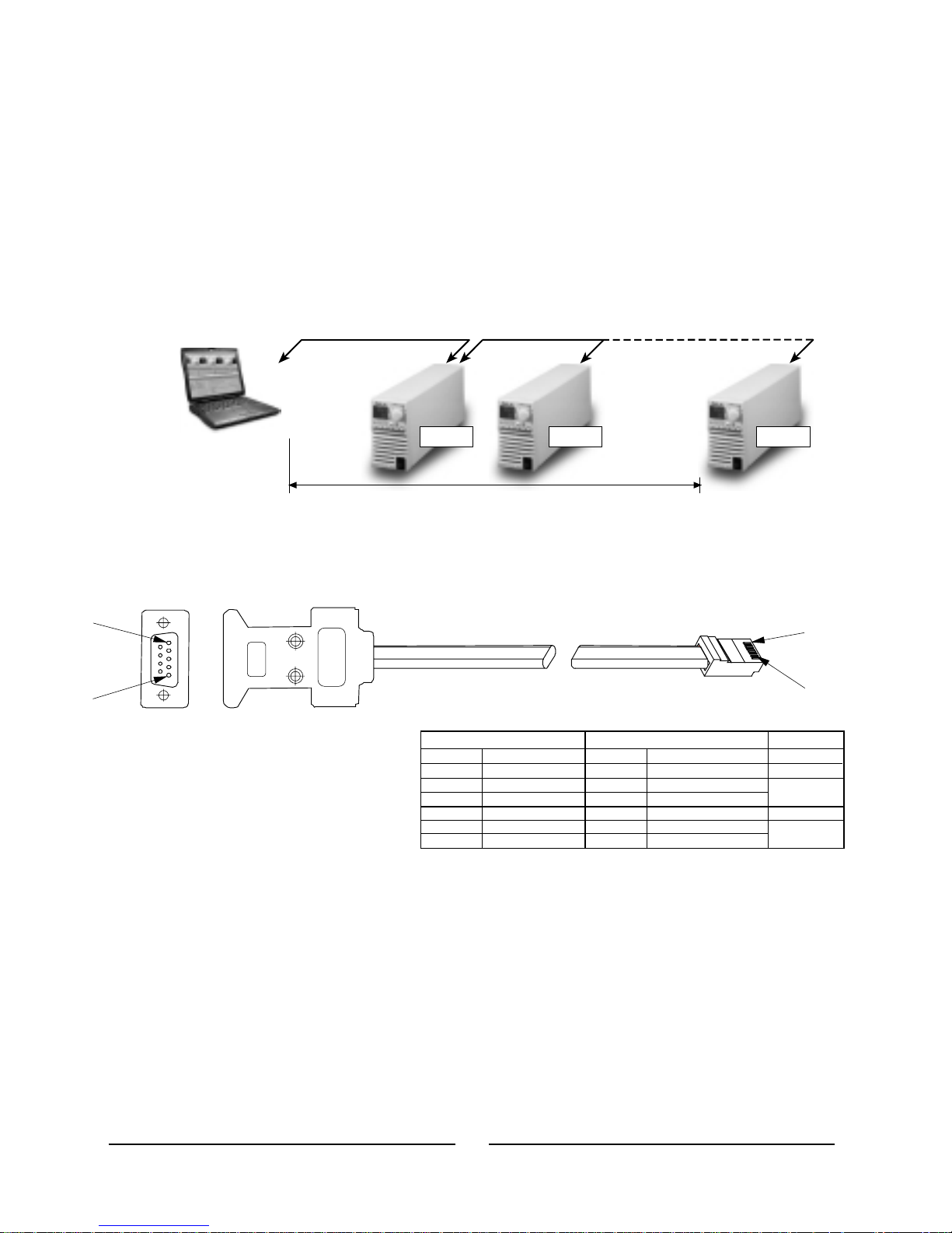
Fig.5-7:RS485cable with
DB-9connector.
Fig.5-6: LinkingZUPunitstoRS485 control.
For operation environments that require high noise immunity or long distance communication, it is
recommended to use the built-in RS485 interface. The RS485 interface is accessible through the
rearpanel In/Out jacks inasimilar way totheRS232.The communication is afour-wiretype. Refer to
par.5-6fordetailedexplanation. Upto31 ZUPunits canbeconnected totheRS485 controlasshown
inFig. 5-6.
Powersupplies arelinked inthesame wayas describedinpar.5.3.4.
TheZUP commandset isdividedinto fourcategories asfollows:1.IDControl
2.InitializationControl
3.OutputControl
4.Status Control
The commands structure, syntax, and registers definition are described in this paragraph as listed
above.
5.4 REMOTE PROGRAMMING VIA RS485
5.4.1 Introduction
5.4.3 Linking power supplies
5.5 ZUP SERIES COMMAND SET DESCRIPTION
5.4.2 RS485 cable ( PC to ZUP ) - NC402
9
8
1
5
4
6
8
5
2
4
PIN NO.
HOUSING
HOUSING
PIN NO.NAME
NAME
TWISTED
PAIR
TWISTED
PAIR
SHIELD
TXD
TXD
SG
RXD
RXD
SHIELD
RXD
RXD
SG
TXD
TXD
9 PIN CONNECTOR
8 PIN CONNECTOR
REMARKS
-
+
+
+
+
-
-
-
8
1
5
1
41
ZUP (1) ZUP (2) ZUP (31)
RS485
1000m max.
RS485 RS485

5.5.1 ID control commands
5.5.2 Initialization control
#
#
Commands
Commands
1 :MDL?;
1 :DCL;
2 :REV?;
2 :ADRn;
3 :RMTn;
4 :RMT?;
Description
Description
Returnsthe powersupply modelidentificationasanASCII string:
Nemic-LambdaZUP(XXV)-(YYA).
XX-Therated outputvoltage
YY-Therated outputcurrent
example:Nemic-Lambda ZUP(6V-33A)
Clearsthe communicationbuffer andthe followingregisters:
1.Operational statusregister
2.Alarm (fault)status register
3.Programming errorregister
Returnsthe softwareversion asanASCII string:
VerXX-YYA.B
XX-The ratedoutput voltage
YY-The ratedoutput current
A.B-Versionidentifier
example:Ver6-331.0
Sets the power supply address. ADR is followed by the address
whichcanbe01 to31.
Sets the power supply to local or remote mode. (This command is active
whentheunitiseitherinLocalorRemotemodes).Transitionfrom Local to
Remotemode ismade viathefront panelonly.
:RMT0;Transitionfrom RemotetoLocalmode.
:RMT1;Transitionfrom latchedRemoteto non-latchedRemote.
:RMT2; Latchedremote: TransitionbacktoLocal mode or to non-latched
Remotecan bemadeviatheserial port(RS232/485).
Atthis mode, the front panel Local/Rem functionis disabled. Escape from
this mode to non -latched remote mode can be made by turning the AC
ON/OFFto OFFandafterapprox.10sec.to ONagain.
Returnstheremote/localsetting. Thereturneddata isan ASCIIstring.
RM1 (The unitis inremotemode)
RM2 (The unitis inlatchedremotemode)
42

5.5.3 Output control
# Commands
1 :VOLn;
2 :VOL!;
Description
Sets the output voltage value in volts. This programmed voltage is the
actual output at constant-voltage mode or the voltage limit at constant
currentmode.Therange ofthevoltagevaluesare asshown intable5-1.
Usealldigitsfor voltageprogramming
Returns the string followed bythe present programmedoutput voltage
value.The actualvoltage rangeisasshownin table5-1.
example: SV5.010 SV08.500
SV
Note:
The ZUP can accept programmed value
higher by up to 5% than the table values,
howeverit isnot recommended toprogram
powersupplyover theratedvoltage.
Model MIN.
MAX.
ZUP6-XY 0.000
6.000
ZUP10-XY 00.000
10.000
ZUP20-XY 00.000
20.000
ZUP36-XY 00.00
36.00
ZUP60-XY 00.00
Table 5-1: Voltage programming range.
Example- :VOL5.010; :VOL08.500;
Example- :CUR3.000; :CUR07.50;
60.00
4 :CURn;
3 :VOL?;
Sets the output current in Ampers. This programmed current is the actual
output current at constant-current mode or the current limit at constant
voltagemode. Theprogramming rangeisshown intable 5-2:
Usealldigitsfor currentprogramming.
Returns the string AV followed by the actual output voltage. The actual
voltagerangeisthe sameastheprogrammingrange.
example: AV5.010 AV08.500
Note:
The ZUP can accept values higher by 5%
thantherating. Itis recommended tosetthe
output current to 105% of the rating if the
unitisrequired tosupplythe ratedcurrent.
Model MIN.
MAX.
ZUP6-33 00.00 33.00
ZUP6-66 00.00
66.00
ZUP6-132 000.00
132.00
ZUP10-20 00.000
20.000
ZUP10-40
ZUP10-80
ZUP20-10
ZUP20-20
ZUP20-40
ZUP36-6
ZUP36-12
ZUP36-24
ZUP60-3.5
ZUP60-7
ZUP60-14
00.00
00.00
00.000
00.000
00.00
0.000
00.000
00.000
0.000
0.000
00.000
40.00
80.00
10.000
20.000
40.00
6.000
12.000
24.000
3.500
7.000
14.000
Table 5-2: Current programming range.
43

5.5.3 Output control continued
#
Commands
5 :CUR!;
6 :CUR?;
7 :OUTn;
8 :OUT?;
9 :FLDn;
10 :FLD?;
Description
Returnsthestring followed by the present programmed output current.
Theprogrammed valuerangeisshownin table5-2.
example- SA3.000 SA07.50
SA
Returns the string followed by the actual output current. The actual
currentrange isthe sameastheprogrammingrange.
example- AA3.000 AA07.50
AA
Setsthe outputtoOnorOff.
:OUT1;- OutputOn
:OUT0;- OutputOff
Returns followedbythe outputOn/Offstatus.
OT1- OutputisOn
OT0- OutputisOff
OT
Setsthe FoldbackprotectiontoOnor Off.
:FLD1; Arm thefoldbackprotection.
:FLD0; Releasethe foldbackprotection.
:FLD2; Cancelthefoldbackprotection.
When the foldback protection is activated, :FLD0; will release the
protection and re-arm it while :FLD2; will cancel the protection. If the
protectionhas notbeen activated,bothcommands arethesame.
Returns followedbytheFoldbackprotectionstatus.
FD1-Foldbackisarmed
FD0-Foldbackisreleased
FD
11 :OVPn;
12 :OVP?;
Sets the over-voltage protection levelin volts. Over-voltagerange settings
aregiven intable 5-3:
example- :OVP08.4;
example- OP08.4
Returns the string followed by the present programmed over-voltage
protectionvalue. Theover-voltagerangeisgiven intable 5-3.
OP
Model MIN.
MAX.
ZUP6-XY 0.00
7.50
ZUP10-XY 00.0 13.0
ZUP20-XY 00.0
24.0
ZUP36-XY 00.0
40.0
ZUP60-XY 00.0
Table 5-3: Over-voltage programming range.
66.0
44

5.5.3 Output control continued
#
Commands
13 :UVPn;
14 :UVP?;
15 :ASTn;
16 :AST?;
Description
Sets the under-voltage protection limits in volts. Under-voltage range
settingsare givenin table5-4:
example- :UVP07.3;
example- UP07.3
Returns the string followed by the presentprogrammed under-voltage
protectionvalue.Theunder-voltage rangeisgiven intable 5-4.
UP
Setsthe auto-restartmodetoOnorOff.
:AST1;- Auto-restartisOn
:AST0;- Auto-restartisOff
Returnsthe string followed bytheauto-restartmodestatus.
AS1-Auto-restartis ON
AS0-Auto-restartis Off
AS
Model MIN.
MAX.
ZUP6-XY 0.00 5.98
ZUP10-XY 0.00 9.97
ZUP20-XY 00.0
19.9
ZUP36-XY 00.0
35.9
ZUP60-XY 00.0
Table 5-4: Under-voltage programming range.
59.8
1.Operational StatusRegister:
The operational status register recordssignals that are partof the powersupply’s normal operation. In
addition to the normal operation data, the register holds an alarm bit which indicates that one of the
alarm(fault) registerbitsis set.Theregister isautomaticallyupdated andreadingit does notchange it’s
content.Clearing the register is done by DCL command. See table 5-5for Operational Status Register
content.
Note:
*1In caseof ACfail,thealarmstatus register‘ACfail’bitwill beset butwillnot setthe alarmbit.
5.5.4 Status control
5.5.4.1 Registers structure
Table 5-5: Operational status register content.
Bit Name
Bit No Meaning
cc/cv
1
‘0’ - Indicates constant voltage, ‘1’ - constant current.
‘1’ - Indicates auto-restart is on, ‘0’ - auto-restart is off.
‘0’ - Indicates foldback protection SRQ is disabled , ‘1’ - enabled.
‘0’ - Indicates over voltage protection SRQ is disabled , ‘1’ - enabled.
‘1’ - Indicates output is on , ‘0’ -output is off.
‘0’ - Indicates over temp. protection SRQ is disabled , ‘1’ - enabled.
‘1’ - Indicates foldback protection is armed.fold
2
ast
3
out
4
srf
5
srv
srt
alarm
6
8
7
‘1’ - Indicates that an alarm register bit is set. (note*1)
45

Bit Name
Bit Name
Bit No
Bit No
Meaning
(*3)
(*3)
(*1)
(*2)
(*3)
Meaning
ovp
not used
‘1’ - Indicates that the over-voltage protection was tripped
‘1’ - Indicates that a failure occurred at the input voltage supply
‘1’ - Indicates an overflow in the communication buffer
‘1’ - Indicates that the foldback protection was activated
‘1’ - Indicates an attempt to program the power supply to a voltage
out of specification limits.
‘1’ - Indicates an attempt to program the power supply to a current
out of specification limits.
‘1’ - Indicates a programming error has occurred
‘1’ - Indicates that the over-temperature protection was tripped
‘1’ - Indicates that an unknown string was received
otp
wrong command
a/c fail
buffer overflow
fold
wrong voltage
prog
wrong current
Table 5-6: Alarm status register content.
Table 5-7: Error codes register content.
2.Alarm StatusRegister:
The alarm status register recordsfault conditions occurringduring powersupply operation. Anyset bit
in this register causes the ‘alarm’ bit in the operational status register to be set. Reading the register
doesnot changeit’scontent.The registerisclearedby:DCL; command.
3.ErrorCodesRegister:
Theerror codes register records errors that occurredduringtheprogrammingof the power supply.Any
set bit in this register causes the ‘prog’ bit in the alarm status register to be set. Reading the register
doesnotchangeit’scontent.The registerisclearedby:DCL; command.
Notes:(*1)Sinceat eachACturnofftheACfailbitis generatedandstored, itis recommendedto
senda :DCL;commandfollowingapplicationofACvoltage tothepowersupply,toclearthe
alarmstatus register.
(*2)FOLDbitis automaticallyresetuponcancellationof FOLDprotection.
(*3)OVP,OTPand‘prog’bitsreset atACturn-offorby:DCL;command.
1
1
2
2
3
3
4
4
5
5
5.5.4.2 Status control commands
# Commands
1 :STA?;
2 :ALM?;
Description
Readsthe operationalstatus registercontent.
Returns the string followed by ASCII characters representing the
register’scontent.
Refertotable5-5 fortheregistercontentdescription.
example- OS00010000
OS
Readsthe alarmstatus registercontent.
Returns the string AL followed by ASCII characters representing the
register’scontent.
Refertotable5-6 fortheregistercontentdescription.
example- AL00000
Incase theOTP orOVPistriggered,the frontpanelcontrolisdisabled untiltheACinputis
recycledby turningtheACON/OFFswitch toOFF andafterapprox. 10sec. toON.
46

5.5.4.2 Status control commands continued
# Commands
3 :STP?;
4 :STT?;
Description
Readstheprogrammingerror registercontent.
Returns the string followed by ASCII characters representing the
register’scontent.
Refertotable5-7 fortheregistercontentdescription.
example- PS00000
PS
Readsthecompletestatus ofthepowersupply.
Thisquery returnsASCII charactersrepresenting the followingdata:
AV<actualvoltage>
SV<voltagesetting>
AA<actualcurrent>
SA<currentsetting>
OS<operationalstatusregister>
AL<alarmstatus register>
PS<programmingerror register>
example:
AV5.010SV5.010AA00.00SA24.31OS00010000AL00000PS00000
5.6 COMMUNICATION PROTOCOL
5.6.1 General Information
5.6.2 Accessing a ZUP Unit
5.6.3 End of Message
The average command processing timeof the ZUP Series is15mSec. Itis not recommended to send
stringsofcommands to theZUPpowersupplywithout consideringtheprocessing time.
Forquery commands ( ? , ! ), wait until theZUP reply message hasbeen completed , beforesending a
new command.
The default condition of the ZUP series isListen mode. In order to access a ZUP unit, for sending a
command or query, the address of that unit should be sent by the host controller (:ADRn;). The ZUP
that recognizes it’saddress becomesactive and can communicate with the hostcontroller.The other
units remain in Listen mode, waiting to receive their address. To access another unit, the controller
should send the address of that unit. The previously active unit changes it’sstate to Listen mode and
theaddressed unitbecomes active.
Eachmessage sentby theZUPisterminatedby anendofmessage.
<CR> carriage returncharacter
<LF> line feedcharacter
47

Service request is a message generated by the ZUP power supply to interrupt the controller. SRQ
can be generated by a power supply fault condition.
Each of the following conditions can generate SRQ message:
1. Over Voltage Protection (OVP).
2. Over Temperature Protection (OTP).
3. Foldback Protection.
The operator decides which of the conditions are defined as faults. Enabling or disabling a condition
from generating SRQ message does not affect the condition within the power supply.
The service request message consists of three characters terminated by EOS<CR><LF>.
The first character identifies the SRQ cause: 1-Foldback , 2-OVP , 3-OTP.
The 2’nd and 3’rd characters identify the ZUP power supply address.
Example: String generated by a ZUP unit :120<CR><LF> , means foldback protection was activated
in power supply address 20.
5.7 SERVICE REQUEST
5.7.1 Service Request (SRQ)
5.7.2 Service Request message
5.7.3. Service request enable/disable commands
48
# Command Description
1 :SRVn; Enable or disable OVP service request.
:SRV1; Enable OVP service request.
:SRV0; Disable OVP service request.
2 :SRV?; Returns QV followed by the OVP service request status.
:QV1; OVP service request enabled.
:QV0; OVP service request disabled.
3 :SRTn; Enable or disable OTP service request.
:SRT1; Enable OTP service request.
:SRT0; Disable OTP service request.
4 :SRT?; Returns QT followed by the OTP service request status.
:QT1; OTP service request enabled.
:QT0; OTP service request disabled.
5 :SRFn; Enable or disable Foldback protection service request.
:SRF1; Enable Foldback protection service request.
:SRF0; Disable Foldback protection service request.
6 :SRF?; Returns QF followed by the Foldback protection service request status
:QF1; Foldback protection service request enabled.
:QF0; Foldback protection service request disabled.

Thischaptercontainsmaintenance andcalibrationinformation forthe ZUPpowersupply series.
Units requiring repair during the warranty period should be returned to a Nemic-Lambda authorized
service facility. Refer to the address listing on the back cover of this user’s manual. Unauthorized
repairsperformedbyother thanauthorizedservice facilitiesmay voidthewarranty.
No routine maintenance of the ZUP power supply is required except for periodic cleaning. To clean,
disconnecttheunitfrom theACsupply andallow 30secfordischarging internalvoltage.Thefrontpanel
and the metal surfacesshould becleaned using a drycloth. Use low pressurecompressed airto blow
dustfromtheunit.
No internal adjustment orcalibration are required.Units thatare returned forservice willbe calibrated
attheservicefacility.ThereisNOREASONto openthe ZUPcover.
As repairs are made only by the manufacturer of authorized service facilities, no part replacement
information will be discussedhere. Incase of failure, unusualor erratic operation ofthe unit, contact a
Nemic-Lambda sales or service facility nearest you. Please refer to the Nemic-Lambda sales offices
listedontheback coverofthisuser’smanual.
ZUP200 Series (ZUP6-33,ZUP10-20,ZUP20-10, ZUP36-6,ZUP60-3.5):T8A 250V
ZUP400 Series (ZUP6-66,ZUP10-40,ZUP20-20, ZUP36-12,ZUP60-7): T10A250V
ZUP800Series (ZUP6-132,ZUP10-80,ZUP20-40,ZUP36-24, ZUP60-14):F20A250V
CHAPTER 6 MAINTENANCE
6.1 INTRODUCTION
6.2 UNITS UNDER WARRANTY
6.3 PERIODIC MAINTENANCE
6.4 ADJUSTMENT AND CALIBRATION
6.5 PART REPLACEMENT AND REPAIRS.
6.6 FUSE RATINGS
49

ID control
initialization
I
42
42
jacks (front panel)
J
21
last setting memory
linking power supplies
local/remote
local sensing
30
40
38, 23
14
L
operational status
otp
output good
over voltage
45
46
37
28
O
parallel operation
parity
33
P
rack mounting
remote sensing
registers structure
RS232
RS485
RXD
RX (RS232)
12
15
45
38, 39
38, 41
41
R
safe start
safety symbols
series operation
shield
status control
SRQ
30
3
35
39, 40, 41
48
S
multiple
loads
15, 16
M
maintenance
49
ac cables
ac fail
accessories
address
adjustment
alarm status
amps display
auto-parallel
automatic start
baud rate
bipolar voltage
buffer overflow
error code
external resistor
external voltage
grounding
humidity
under voltage
volts display
TXD
TX (RS232)
wire size
wrong command
foldback
fuse
display
calibration
communication
constant current
constant voltage
cooling
cv indicator
cc indicator
6
46
6
24,26,38
49
46
23
33
30
38
36
46
39
45
46
31
32
2
8
28
23
46
41
39
13
46
23, 29
2, 49
23
49
47
27
27
12
23
23
ZERO-UP USER’S MANUAL INDEX
A
B
E
G
H
U
V
T
W
F
D
C
50

ZERO-UP 200W/400W/800W
PROGRAMMABLE DC POWER SUPPLIES
UP
LAMBDA GROUP
Europe / North America
IA549-04-01D
GLOBAL NETWORK
GLOBAL NETWORK
AD0005
Canada
Lambda Electronics (Canada) Inc.
16829B Hymus Blvd.
Kirkland, Quebec. H9H 3L4 Canada
TEL: +514-695-8330 FAX: +514-695-8168
Italy
Lambda Electronics s.r.l.
Via F. Ili Gracchi 36
20092 Cinisello Balsamo, Milano, Italy
TEL: +39-02-660-40540 FAX: +39-02-660-40650
U.K.
Coutant Lambda Ltd..
Kingsley Avenue Ilfracombe, Devon
EX 34 8ES United Kingdom
TEL: +44-1271-856600 FAX: +44-1271-864894
http://www.lambda-gb.com
France
Lambda Coutant S.A.
91940 LES ULIS Cedex, France
TEL: +33-1-60-127400 FAX: +33-1-60-127401
Germany
Lambda Electronics GmbH
Josef-Hund-Straße 1
D-77855 Achern, Germany
TEL: +49-7841-6806-0 FAX: +49-7841-5000
USA
Lambda Electronics Inc.
515 Broad Hollow Rd.
Melville, New York 11747-3700 USA
TEL: +631-694-4200 FAX: +631-293-0519
http://www.lambdapower.com
Sweden & Norway
Lambda Scandinavia AB.
Sagvagen 2
SE-184 25 Akersberga, Sweden
TEL: +46-8-598-94090 FAX: +46-8-540-66096
http://www.lambda-scandinavia.com
P.O.Box 546
Japan
Densei-Lambda K.K.
Head Office: 1-11-15 Hagashi-gotanda,
Shinagawa-ku, Tokyo, Japan 141-0022
TEL: +81-3-3447-4411 FAX: +81-3-3447-7784
http://www.densei-lambda.com
China
Densei-Lambda K.K..
Beijing Office
Room B1911 Hui Bin Offices No.8
Beichen Dong Str. Chaoyang District
Beijing, 100101 China
TEL: +86-10-6499-3441 FAX: +86-10-6499-3507
Korea
Densei Lambda K.K. Korea Branch
6F Sungok Bldg. 4-1 Soonae-Dong
Boondang-Gu Sungnam-Shi Kyonggi-Do, Korea
TEL: +82-2-556-1171 FAX: +82-2-555-2706
Malaysia
Nemic-Lambda (M) SDN. BHD.
No.8 1F,Tinkat Talang 1, Terman Emas,
13600 Prai, Penang, Malaysia
TEL: +60-4-399-7388 FAX: +60-4-399-7381
Singapore
Nemic-Lambda (S) PTE Ltd.
Blk 1008 Toa Payoh North # 06-01/08
Singapore 318996
TEL: +65-251-7211 FAX: +65-250-9171
Israel
Nemic Lambda Ltd.
Sales Office:
Kibbutz Givat Hashlosha Tel-Aviv 48800, Israel
TEL: +972-3-9024-333 FAX: +972-3-9024-777
Plant:
POB 500 Karmiel Industrial Zone 20101, Israel
TEL: +972-4-9887-491 FAX: +972- 4-9583-347
http://www.nemic.co.il
Hong Kong
Densei Lambda Hong Kong Branch
Rm. 8, 27/F, Mega Trade Center
1 Mei Wan St. Tsuen Wan, N.T. Hong Kong
TEL: +852-2420-6693 FAX: +852-2420-3362
Malaysia
Nemic-Lambda (M) SDN. BHD.
No.7.3, 7th Floor, Jaya Shopping Center,
Petaling Jaya 46100 Selangor, D.E, Malaysia
TEL: +60-3-757-8800 FAX: +60-3-758-2400
Jalan Semangat Section 14,
DENSEI-LAMBDA GROUP
Asia / Far East / Middle East
DENSEI-LAMBDA
 Loading...