

Page 1

2011 Getting Started Guide
The contents of this printed guide and
accompanying exercise CD were originally
created for Nemetschek Vectorworks, Inc.
by Kevin Lee Allen.
Page 2

© 2010 Nemetschek Vectorworks, Inc.
All rights reserved. No part of this book may be reproduced or transmitted in any form by any means, electronic or mechanical, including
photocopying, recording, faxing, emailing, posting online or by any information storage and retrieval system, without prior written permission of the
publisher. Published in the United States.
Vectorworks is a registered trademark of Nemetschek Vectorworks, Inc., in the United States and other countries. Windows is a registered
trademark of Microsoft Corporation in the United States and other countries. Macintosh is a trademark of Apple Computer, Inc., registered in the
United States and other countries. Adobe, Acrobat and Reader are registered trademarks of Adobe Systems in the United States and other countries.
The information in this book is distributed on an “as is” basis, without warranty. While every precaution has been taken in the preparation of
this book, neither the author nor Nemetschek Vectorworks, Inc., shall have any liability to any person or entity with respect to any loss or damage
caused or alleged to be caused directly or indirectly by the information contained in this book or by the computer software described in it.
For additional Vectorworks training information, or to purchase copies of this book, please call us, in the United States at (410) 290-5114 or
visit Vectorworks.net/training online.
Page 3

Table of Contents
Introduction ..............................................................................................................................5
How to Use this Guide ....................................................................................................6
Getting Help ....................................................................................................................8
Section 1: Organizing Your Workflow ..................................................................................... 11
The Screen ...................................................................................................................11
Palettes .........................................................................................................................12
Document Window ........................................................................................................14
Preferences ...................................................................................................................15
Workspaces ..................................................................................................................16
Organization ..................................................................................................................18
Section 2: Stationery Documents ...........................................................................................21
Section 3: Drawing & Modeling ..............................................................................................23
Layer Plane and Screen Plane .....................................................................................23
2D Primitive Tools .........................................................................................................24
2D Modifying Tools ........................................................................................................26
2D Commands ..............................................................................................................28
3D Tools ........................................................................................................................29
3D Commands ..............................................................................................................32
Manipulating 2D and 3D Objects ..................................................................................38
Section 4: Hybrid Tools ...........................................................................................................41
Locus Points .................................................................................................................42
Wall Tools ......................................................................................................................42
Floor ..............................................................................................................................43
Door and Window Tools ................................................................................................43
Curtain Tool ...................................................................................................................44
Create Seating Layout ..................................................................................................45
Curved Wall Tool ...........................................................................................................45
Wall Sculpting ...............................................................................................................46
Rotated Views ...............................................................................................................47
Column Tools ................................................................................................................48
Section 5: Understanding Symbols ........................................................................................49
Page 4

Symbol Geometry .........................................................................................................50
Available Resources .....................................................................................................50
Inserting Symbols .........................................................................................................50
Symbol Types ...............................................................................................................51
Modifying Symbols ........................................................................................................52
Editing Symbols ............................................................................................................52
File Referencing ............................................................................................................53
Exercise ........................................................................................................................53
Section 6: Drawing a Light Plot ..............................................................................................55
Label Legends ..............................................................................................................55
Focus Point Objects ......................................................................................................56
Lighting Positions ..........................................................................................................57
Trusses .........................................................................................................................59
Inserting/Modifying Instruments ....................................................................................59
Vertical Lighting Positions .............................................................................................62
Projection/Monitor Tools ................................................................................................63
Photometrics/PhotoGrid ................................................................................................63
Basic Scripting ..............................................................................................................64
Custom Lighting Symbols .............................................................................................65
Create Plot and Model View..........................................................................................65
Paperwork .....................................................................................................................68
Exercise ........................................................................................................................68
Section 7: Visualizing your Design .........................................................................................69
Rendering Modes ..........................................................................................................70
Layer Backgrounds .......................................................................................................71
Textures ........................................................................................................................73
Shaders .........................................................................................................................75
Textures for the Theatre Project ....................................................................................78
Assigning Textures ........................................................................................................79
Textures and Walls ........................................................................................................80
Textures in the OIP .......................................................................................................80
Mapping ........................................................................................................................80
Creating Image Props ...................................................................................................81
Decals ...........................................................................................................................83
Unified View ..................................................................................................................83
Camera Tool ..................................................................................................................84
Page 5

Setting 3D View.............................................................................................................85
Lighting in the 3D World ................................................................................................85
Section 8: Presenting your Drawings .....................................................................................91
Viewports and Sheet Layers .........................................................................................91
Theatre Project–Next Steps ..........................................................................................93
Working on the Sheet Layer..........................................................................................94
Working in the Viewport ................................................................................................95
Adding Dimensions .......................................................................................................96
Working with Text ..........................................................................................................98
Lighting Paperwork .......................................................................................................99
Printing ..........................................................................................................................99
Section 9: Conclusion ...........................................................................................................101
Additional Resources ..................................................................................................101
Acknowledgements .....................................................................................................102
About the Author .........................................................................................................103
Page 6

Page 7

Introduction
This guide is designed to teach the basics of working with the Vectorworks Spotlight and
Renderworks software tools. The text and illustrations show some of many possible
workflows. Your own methods may vary slightly over time. This book only begins to scrape
the surface as to what you can do with Vectorworks.
All of the screen shots here show the MacOS. Windows users will find the same information in
the same places, although it may look a bit different. From time to time, I have inserted
information about keyboard shortcuts. Again, I generally make reference to the Command key.
On a PC, that usually means the Control key. There is a complete reference to these shortcuts
in the Vectorworks help files, complete with cross referencing the two operating systems.
The approach contained here stresses the architectural concept of Building Information
Modeling (BIM). Simply put, this is working and collaborating in the 3D environment. On a
more complex level, BIM allows 2D and 3D representations of objects connected with data.
On a collaborative level, this allows a set designer to provide a void—and technical directors
to fill parts of that void with structure, lighting designers to add instrumentation, sound
designers to insert microphones or speakers, and video designers to add screens and gear.
BIM in the performing arts allows for a truly collaborative space for the various partners to
work and share information across a series of referenced files.
This guide describes a professional workflow that allows designers and technicians to
develop a project from beginning to end, collaborate effectively and produce both
presentational materials and construction documents that evolve with the design.
Working in the 3D space with dynamic links to presentations (sheet layers) keeps the entire
project constantly updated.
Using Metric Units with Exercises
All exercise data set files for this tutorial are set to use imperial units.
Vectorworks Spotlight 2011 Getting St arted G uide | 5
Page 8

How to Use this Guide
Work through the guide and the exercises. Each exercise or process, no matter how simple,
leads to the next exercise. It helps to have the hands and the mind work through the simple
steps before reaching more complex problems.
This manual covers a lot of ground quickly.
Yet, it just skims the surface of a powerful
application. Everything is here so that you
can get up to speed waith Vectorworks
Spotlight quickly. The following are points to
keep in mind as you work through the guide:
• Alternate methods are shown for
activating/using many tools, commands,
and modes.
• Use what works best for you.
• Experiment with different tools and
techniques.
• Watch for SmartCursor cues, which
appear as you hover your cursor over
significant drawing – object geometry.
• The text assumes you are familiar with
basic computer terms and basic theatrical
concepts.
• Save early, and save often. Save after
every operation.
• Establish a back-up ritual. Macintosh
users should take advantage of the Time
Machine feature within the OS.
• Use the Vectorworks auto back-up in
addition to your own back up plan.
• Save–As frequently, so you can always
access earlier ideas and solutions.
• Use symbols, and get to know and
understand them early on.
• Most tools have options, available for
selection in the Tool Bar. See the illustration
on page 11.
• Don’t be concerned if you do not
understand this entire introduction, it will all
be explained as you make your way through
this guide.
6 | Vectorworks Spotlight 2011 Getting St arted G uide
Page 9

Working through the Guide
This guide is built on a plan of exercises and
two projects. Each time a concept or set of
concepts is presented, there will be an
associated exercise created to practice the
base skills presented. The exercises are
important for new and experienced users
alike, and working through the exercises
lays the foundation for more complex tasks.
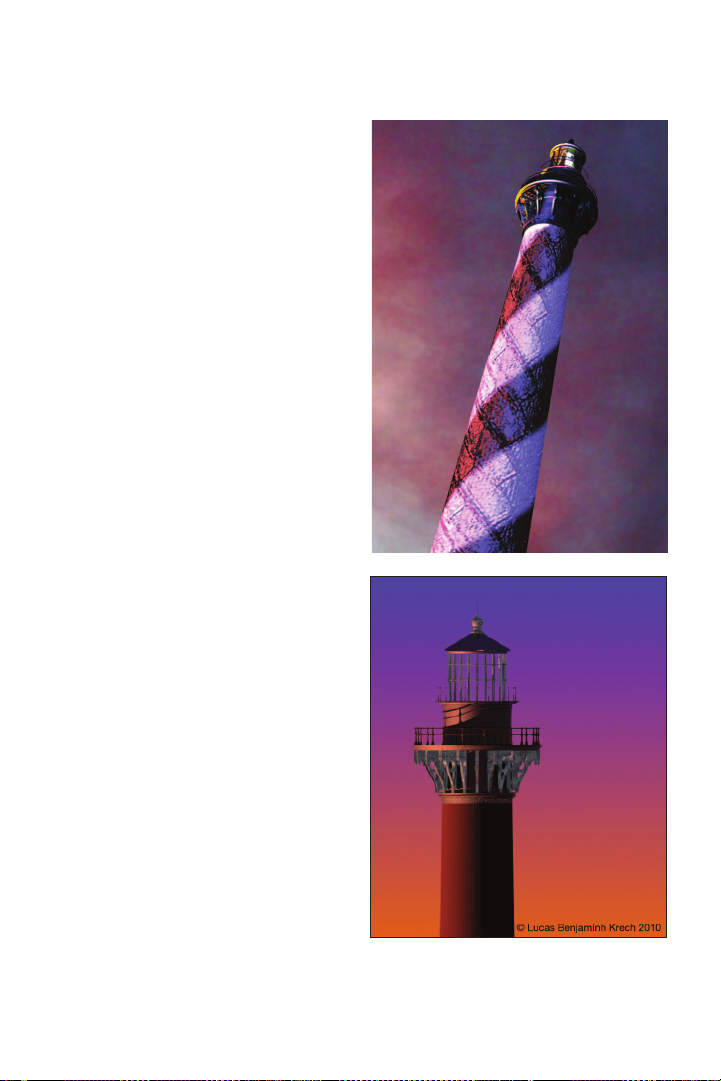
The Lighthouse. The Cape Hatteras
Lighthouse is a complex 3D model briefly
illustrated in the text but strongly suggested
as a challenge. The lighthouse project brings
together all of the exercises. It is a daunting
and intimidating task when viewed in total,
however, it is actually many simple tasks
combined. Users who can complete the
lighthouse can generally model and present
any other professional challenge that comes
their way.
The Theatre Project. In the course of the
text users will create a basic theatre space,
a set, light plot, design visualizations,
and a set of drawings from which these
designs could be executed. Tangentially,
completing this project will also assist users
in configuring the application for future
assignments.
Vectorworks Spotlight 2011 Getting St arted G uide | 7
Page 10

Getting Help
Vectorworks Help
With the Vectorworks application installed
and up and running, select Vectorworks
Help from the Help menu to open the Help
application. Alternately, select the “What’s
This?” command, which will change your
cursor to an arrow with a question mark.
You may then use this cursor to select an
object within Vectorworks, which will send
you to the appropriate location within the
Vectorworks Help application.
The Vectorworks Help application is a robust
depository of information that users can
modify and adjust to their needs. The Help
application can be automatically updated.
The Help Application Window is divided into
two columns. The left column provides
navigation, and the right column provides
information. Enter search criteria where it
says “Enter text to search.” Results will be
displayed in the right column. Selecting a
search result will display the search topic.
Search results can be saved as Favorites by
clicking on the star icon. You may also add
comments and other information.
8 | Vectorworks Spotlight 2011 Getting St arted G uide
Page 11

Additional Help
At http://vectorworks.net it is possible to access
a number of additional learning and informational tools, including user forums, mailing lists and
demonstration videos and other guides (http://
www.vectorworks.net/training/guides.php). The
Vectorworks online community (http://www.
vectorworks.net/community/index.php) is
dynamic and supportive. Join the user forums
and e-mail lists.
There are specific lists and forums for theatre
and Spotlight, but do not neglect the general
forums and lists. Many issues that arise in
Spotlight are familiar to the larger groups of
users. Questions posed to the online
community are often answered almost
immediately. Vectorworks is used widely
internationally. Whenever you are working,
there are others working around the world.
Links to the online community and RSS feeds
are in the favorites tab of the Help Application.
User links may also be added.
Application Resources
On a Mac, the Vectorworks directory should be
in the Applications folder on your hard drive.
On a PC, this directory should be in the
Program Files folder.
The libraries are an important feature that will
take time to explore. Critically, the ObjectsEntertainment directory contains symbols
(pre–drawn objects) for nearly all of the lighting
instruments available. There are also lighting
accessories, lighting positions, speaker
symbols, and truss symbols.
There are also libraries for textures (used to
“paint” scenic elements and create gobo
projections). The file names are generally
descriptive of the file contents.
Symbols are 2D, 3D, or combined 2D/3D
(Hybrid) objects, that can be used repetitively
and can have critical information attached to
them via a data record. Symbols will be
discussed throughout this guide.
PDF manuals can be accessed from the Help
table of contents.
Vectorworks Spotlight 2011 Getting St arted G uide | 9
Page 12

10 | Vectorworks Spotlight 2011 Getting St arted G uide
Page 13

Section 1: Organizing
Your Workow
This section provides an overview of the Vectorworks environment and basic definitions.
Everything described in this section will be reviewed in greater detail throughout the Guide
The Screen
When rst opening the Vectorworks
Spotlight application, your screen should
look like this illustration. If it does not, go to
the Menu at the top of the screen and select
Tools> Workspaces>Spotlight.
On the left side of your screen you should
see the Basic tool palette and the Tool Sets
palette, which allow you to access additional
tools for particular jobs. The Attributes
palette and the Snapping palette are also to
the left. On the right you should see the
Object Information palette (OIP), Navigation
palette, Visualization palette and Resource
browser.
At the top of the active window, you will see
the View bar and the Tool Bar. The Message
bar is located at the bottom of the window.
Vectorworks Spotlight 2011 Getting St arted G uide | 11
Page 14

Palettes
Basic Tool Set
The Basic tool set provides ready access to
a collection of 2D drawing tools, 2D and 3D
drawing modifiers, and basic dimensioning
tools.
Tool Sets
Tool sets are collections of tools grouped for
specific tasks. Note, for example that there
is a Dimensioning tool set in addition to the
Dimensioning tools provided in the Basic
tool set. In the Dimensioning tool set the
basic tools are joined by additional tools.
Attributes
The Attributes palette sets various graphic
attributes of 2D and 3D objects. When an
object is selected, the line, fill, line style, and
opacity of an object may be changed.
Constraints
The Constraints palette sets options for
drawing with precise alignment. Constraints
can be temporarily turned off by pressing
and holding the apostrophe (‘) key.
Users may set Preferences for the
constraints and the displayed grid by
double–clicking on any of the constraint
icons. Constraints help with precise drawing
and provide cues to the Smart Cursor.
SmartCursor. The Smart Cursor provides a
series of cues displayed as text at the
cursor’s current location. The Smart Cursor
can create snaps to specic points relative
to other objects.
Smart Points. Smart Points allow the use
of existing geometry as drawing guides.
When Smart Points snapping is on, a Smart
Point can be dened by pausing the cursor
over an object point and pressing the “T”
key. Drawing can then be aligned with that
point. The alignment is visually shown with a
dotted red line.
Working Planes.The Working Planes
palette is not opened by default. For the
purposes of working through this book, go
to Window>palettes>Working Plane to
open the palette. Locate the palette so it is
accessible, but not in the way of drawing.
Simply explained, working planes allow you
to change the base plane on which you are
drawing. Typically, the base plane is a at
horizontal plane. This palette will allow you
to access multiple saved base planes.
Object Information Palette (OIP). The
Object Information palette (OIP) is a critical
design control point; every object selected
in Vectorworks can be manipulated via
the OIP. When you can’t gure out how to
modify something, look here rst.
12 | Vectorworks Spotlight 2011 Getting St arted G uide
Page 15

The OIP has three tabs: Shape, Data,
and Render. Shape affects size, location,
and specic parameters associated with
different types of objects. Data references
information associated with the object for
use in worksheets, and Render affects the
look of 3D objects in presentations.
Resource Browser,The Resource browser
allows access to symbols, textures, and
other data within your le and other les
that may or may not be open. Select the
disclosure arrow at the top right of the
Resource browser and select Add New
Favorite Files. Navigate to the Vectorworks
directory and add the following les to your
favorites:
• Libraries>Defaults>Renderworks-
Textures>Textures_Default.vwx
• Libraries>Objects-
Entertainment>Lighting-ETC.vwx
• Libraries>Textures-Gobo>Rosco-
Gobos>Rosco Abstract.vwx
• Libraries>Objects-
Entertainment>Lighting Positions Imp.v wx
• Libraries>Objects-Building
Architecture & Interior>Detail-Molding
Proles Copper Beech Millwork.vwx
• Libraries>Objects-Building
Architecture & Interior>FurnitureFurnishings and Scenic Elements.vwx
• Libraries>Objects-Building Services>
Electrical-Accurate Lamps-Imp.vwx
Libraries>Default Content is available from
within the Vectorworks application. For
example, the Default Textures can be
accessed from the OIP and when editing
class denitions.
Navigation
The Navigation palette will be covered
thoroughly in Organizing the Drawing, but
for the moment notice that this palette
allows you to quickly access Classes,
Design Layers, Sheet Layers, Viewports,
Saved Views and References. Each of
these items will be covered and dened.
From the Navigation palette you can
activate, navigate, and control visibilities.
Visualization
The Visualization palette will be covered in
depth in Drawing a Light Plot. Note that this
palette allows control of Light Objects and
Camera Objects.
Vectorworks Spotlight 2011 Getting St arted G uide | 13
Page 16

Document Window
View Bar
The View bar allows ready access to a
number of important functions. View bar
functions can be hidden and displayed from
the drop-down list accessed via the
Disclosure Arrow on the right of the View
bar. We will cover most of the View bar
elsewhere, but from the left you will see
forward and backward arrows; clicking on
these will take you back and forth between
recent document views. Skip to the center
right and you will see two magnifying glass
icons that take you to a view of either a
selected item or to a view of all items in the
visible drawing (if nothing is selected).
Command-6 on a Mac and Control-6 on a
PC have the same functionality.
There is a drop–down menu for your view of
the drawing. Typically, set to Top/Plan
(Command-5), which is the 2D view from
overhead.
Top is a 3D overhead view, and the others
should all make logical sense. You may also
access each of these views from your
numeric keypad with 5 being Plan, 2 being
Front, etc.
Tool B a r
The Tool bar displays different options
available for each tool selected from the
Basic tool set or one of the task–specific
tool sets. On the right of the Tool bar you
have Quick Preferences; selections
available from the Vectorworks Preferences
allowing the user to make rapid interface
changes, as desired. Select available
options via the Disclosure Arrow on the right
of the Tool bar.
Message Bar
The Message Bar displays precise
information about the location of the cursor in
the drawing space. This display can be
affected by selecting preferences accessed
by clicking the Disclosure Arrow in the far
right hand corner of the screen. Additionally,
the Message Bar displays important alerts,
back-up information and rendering progress.
Moving the View
To pan across the drawing at any time (even
if a tool or command is active) hold down
the Space bar and drag the cursor. This
action is referred to as Boomerang mode
since you will be returned to the active tool
as soon as the space bar is released.
Boomerang Mode does not work when
editing text.
You may also directly select the Pan tool
from the Basic tool set.
14 | Vectorworks Spotlight 2011 Getting St arted G uide
Page 17

Zooming
By default, the applications preferences set
the scroll wheel of the mouse to zoom in
and out. Similarly, two fingers on a
multi-touch track pad will zoom in and out of
a drawing.
From the View bar, click Fit to Objects
(Command-6). The view is adjusted to fit the
Preferences
Application Preferences
On a Mac, the Application Preferences can
be accessed from the Vectorworks Menu.
On either a Mac or a PC, the Application
Preferences can be accessed by navigating
to Tools>Options>Application
Preferences.
Select the Session tab, and then enter 100
in the maximum number of undos eld.
Verify or adjust other settings as desired.
These are application–wide settings.
Document Preferences
File>Document Settings>Document
Preferences allows you to set parameters
specic to the active le. In the United
States, select the Dimensions tab and set
the Dimension Standard to “Arch.”
selected object to the screen. When nothing
is selected, the same action will fit all
objects to the screen.
Command-1 will zoom in, Command-2
will zoom out, Command-3 returns to the
last view, and Command-4 shows the
full–page view.
Unit Preferences
File>Document Settings>Units sets the
options for dimensioning and specic units/
measurement systems.
Vectorworks Spotlight 2011 Getting St arted G uide | 15
Page 18

Spotlight Preferences
File>Document Settings>Spotlight
Preferences allows you to establish
specic settings for conguring the plot and
communicating with Lightwright.
(http://www.mckernon.com)
Workspaces
Quick Preferences
Some preferences can be toggled from
the Tool bar. Available Preferences may be
added or deleted by selecting the drop–
down menu via the Disclosure Arrow on the
right side of the Tool bar.
The Spotlight Workspace
Vectorworks is completely customizable.
Adjusting the menu and palette layout is the
most readily apparent way that the average
user can make Vectorworks their own.
Editing/Creating Workspaces
Go to Tools>Workspaces> Workspace
Editor and you will have several choices:
• Edit the current workspace
• Edit a copy of the current workspace
• Create a new workspace.
Avoid creating a new workspace and avoid
editing one of the workspaces that are
provided in the installation process.
Creating a new workspace gives you a
blank slate.
Making a copy of the Spotlight Workspace
gives you an excellent foundation on which
to build, and you always have the original to
go back to for reference. You can name the
copy whatever you like to differentiate your
workspace from the original.
Most users have several of their own
workspaces. Typically at least one for use
on a laptop and one for use with a larger
screen. Over time you may nd additional
tools or plug-ins that you would like to add
to Vectorworks. Some come with their own
workspace. Other add-ons or plug-ins need
to be added to any workspace where you
might want to use them.
For example, lighting designers, may be
interested in utilizing the visualization
capabilities of ESP Vision (http://espvision.
com) and would want to modify a
workspace. If you work in television or
corporate theatre, you will notice the Video
Screen capabilities available in the Spotlight
tool set. Developer Andrew Dunning also
offers a more powerful commercial version.
16 | Vectorworks Spotlight 2011 Getting St arted G uide
Page 19

Use of the commercial version requires
adding plug-In les and modifying your
wor kspace(s).
From the workspace editor, we will make a
copy of the Spotlight Workspace just to see
how this is done. You will now have a window
with three tabs that allow you to edit the
Menus, tools and Misc Keys. Grab the New
Menu from the left column and drag over to
the right column. Name it. Note that you can
readily rename the other menus just as you
can rename a le. You can also delete a
menu by selecting and hitting the delete key.
Once you have a new menu, you can drag
other items from the left column into your new
menu, and arrange them as you like.
You can also edit the contextual menus to
readily access an often–used tool from the
right mouse button.
From the tools tab, you can modify your
palettes in much the same way. You can
totally reorganize the tool sets to meet your
work ow and needs.
In both cases, you can alter the keystrokes
required to bring up a specic tool.
Vectorworks Spotlight 2011 Getting St arted G uide | 17
Page 20

Organization
Vectorworks documents use several
conventions for organization:
• Classes
• Design Layers
• Sheet Layers
• Viewports
• Saved Views
• Referenced Files
When working in a team or just to keep les
smaller, develop different elements in
different les, and then use the File
Referencing features to bring all of the
elements together.
Let’s look at the Organization dialogue box.
Select Tools>Organization. Note the
differences and similarities between this
dialogue and the Navigation palette. Also be
aware that this dialogue can be accessed
from the Edit Classes and Edit Layers
buttons in the View bar.
Classes
Classes are used to assign graphic attributes
and to control visibility in drawing and when
creating Viewports for presentation. Classes
can be used for objects on different layers.
Like Design Layers, they can be used to
control what is visible. Vectorworks starts by
giving you two classes: Dimension and None.
Begin by editing the Dimension class. Check
Use at Creation and set the ll color to none
so that your Dimension text does not conceal
other details.
18 | Vectorworks Spotlight 2011 Getting St arted G uide
Create a Normal Weight class that has
Use at Creation checked and set the line
weight to a medium width, about twice the
width of the Dimension Class line weight.
Also create a class called Section Style
with a thick line weight and cross hatch
pattern ll. Vectorworks will call for this
class. Save in your Default.sta document
as described below.
Classes truly allow full use of Vectorworks,
and, as a best practice, no object should be
drawn without having a class assigned.
Going further, consider that your theatre
walls may have one color and your set wall
to have another color. By using classes to
assign these attributes, when the color of
the set changes, you can change all of the
walls at once. Similarly, you would want
different classes to distinguish the Grand
Drape from the masking.
Page 21

Design Layers
The design layer is the basic level of
organization. Think of layers as sheets of
vellum on a table; architects use layers to
distinguish oors of a building. Many
theatrical designers create layers for the
theatre, the set, the light plot, and the sound
plot. Each design layer can have a different
scale and can be set to different Z
elevations.
This is a basic layer structure:
• Sound Plot
• Light Plot
• Scenery
• Audience
• Theatre Architecture
• Audience Seating
• Tra ce La yer
A PDF or a JPEG of the theatre, ballroom,
or television studio architecture can be
imported to a bottom tracing layer. On top of
that you may have an architecture layer and
a master layer for the set and other
information. Design layers can be used to
create specic physical elements that may
be saved as symbols and placed in the layer
with the architecture or the set.
Layer visibility is controlled in the
Organization dialogue or via the
Navigation palette.
The enclosed DVD includes a sample
document so that you can examine a basic
class structure and another that shows
basic layers needed for every drawing.
Sheet Layers
Sheet Layers are used for presenting
drawings. Sheet Layers are always in a 1:1/
Full Size or Actual Scale. We’ll discuss
Viewports and Sheet Layers for
presentations in the Presenting your
Drawings section on page 91.
Saved Views
Saved Views (in the View bar) allow you to
revert to previously saved views quickly at
any time. There may be an area of detail
that you continually need to return to in plan;
a Saved View will allow that. Views can
have different layers and classes visible.
Saved Views are also very useful for looking
at scenes rendered with lights focused,
lighting levels set, and gobos inserted as
you adjust the light levels.
Vectorworks Spotlight 2011 Getting St arted G uide | 19
Page 22

Page 23

Section 2: Stationery
Documents
When creating a new document (File>New), Vectorworks will ask if you want to create a
blank document or use a stationery le. Vectorworks comes with a selection of stationery
les, most geared for architecture. It is a useful time saver to create and evolve your own
stationery les.
When you go to File>Save As Template and
save a le as Default.sta Vectorworks will
automatically le your template in the proper
place. You will be able to access your saved
settings whenever you create a new le.
Go to File>New to create a new document;
you will have a choice between selecting a
blank document or using a template. A
template le has various predetermined characteristics. Select Create Blank Document
and we will determine our own parameters.
Go to File>Page Setup. Here you establish the size of the page and select a printer. The
printer does not need to be selected now if you will be printing from a PDF, which is the
recommended practice. “Draw” on a sheet size that is the same as the size on which you
plan to print. Let’s establish an Architectural size D sheet (24” by 36”). If you are not
connected to a plotter, you will have to check “Choose size unavailable in printer setup” on
the top right and then US Arch D from the drop–down menu. On the left select “Show page
boundary” and de-select “Show page breaks.” Showing breaks will clutter your drawing area
with division markers, likely dividing the 24 x 36 inch pages into 8 ½ x 11 inch chunks.
Click OK and now we will begin to make some specic settings.
Vectorworks Spotlight 2011 Getting St arted G uide | 21
Page 24

Go to File>Document Settings>
Document Preferences; you will see three
tabs. We will leave the left and right tabs set
to the default; select the Dimensions tab.
Make sure the three check boxes are
checked and that the drop–down menu is
set to Arch. Click OK.
Go to File>Document Settings>Units and
be sure that your document is set to feet
and inches – or metric units – as
appropriate. Of course, if you design the
show in one system, you can go back later
and convert the document from imperial to
metric, or vice versa. Click OK.
Go to the View bar. There should be a data
eld that says, 1:1 and next to that, on the
right, there should be a ruler icon. If not,
select Layer Scale from the View bar menu.
Click on the ruler and set the scale to
1/2”=1’-0” and click OK.
Select Tools>Options>Line Thickness
and review the default settings.
Select and set a default font. With nothing
selected on the page, go to Tex t >Font and
select your preferred font. It should be
something generally readable and if you will
be sharing les, the font should be one that
works across platforms and is installed on
your colleagues’ systems. You can make
adjustments to text later in the OIP or Text
menu.
Create the classes as indicated above.
Now, save the le settings as a template le.
Go to File>Save as Template and the Save
as Vectorworks Drawing Template dialog
box will open and suggest that the le
Default.sta be saved in the Templates
folder of your User folder or the Vectorworks
Directory. Click Save. Also save a copy of
your default le as DefaultLetter.sta. In this
le, change the document size to a standard
letter–size page. All new documents, unless
you select another template, will have the
attributes you have specied set by default.
You will likely need to save over this
Default.sta le several times as you further
adjust to the program.
22 | Vectorworks Spotlight 2011 Getting St arted G uide
Page 25

Section 3: Drawing &
Modeling
Vectorworks provides many ways to draw. For the user, it is a matter of choice to determine
what works best for him or her and/or specic scenarios. Flexibility in drawing is one of the
many great reasons to use Vectorworks.
Layer Plane and Screen Plane
These are not drawing modes, but planar
modes to draw within. 2D objects drawn in
the Layer Plane will rotate in 3D space. 2D
objects drawn in the Screen Plane will
always be seen as facing the screen, no
matter the 3D view and they will not rotate in
3D space.
Planes are useful when preparing to extrude
an object from 2D into 3D.
The Layer Plane is indicated by a pink box,
You may choose whether to draw in Layer or
Screen Plane from the drop–down menu on
the View bar. You may change what plane an
object is assigned to by selecting the object
and changing the plane in the OIP.
unless you have changed the color in your
preferences.
Vectorworks Spotlight 2011 Getting St arted G uide | 23
Page 26

2D Primitive Tools
Open a copy of your DefaultLetter.sta le and use this le to work along as described below.
Switch the plane from Layer Plane to Screen Plane in the View Bar.
You can easily nd which tool is which by
hovering and waiting for the descriptive text
to appear or by going to the Help les.
Rectangle
Begin by selecting the Rectangle tool.
Notice the options in the Tool bar change
when a tool is selected. Each mode or
option available in the Tool bar offers a
different way of drawing. By hovering over
the mode icons you will see descriptive text
appearing to describe the mode. There will
also be text in the Mode bar that describes
the active option.
These options will vary with the tool
selected. In each case, as you explore the
application try every mode available.
24 | Vectorworks Spotlight 2011 Getting St arted G uide
You can simply begin to draw by clicking
and dragging. As soon as you begin to draw,
you will note the appearance of the Floating
Data bar (FDB). Hit the Tab key to select the
rst eld in the FDB and enter a specic
dimension, tab to the next eld, repeat, and
click the mouse button. You have created a
specically sized shape!
Draw a few rectangles and note the
highlight color when you hover over a shape
and the change in color when you select a
shape. You can select multiple objects by
pressing and holding the Shift key or doing
a marquee selection (click and drag with the
2D Selection tool).
Page 27

Select an existing rectangle and note that
you can move it or resize it interactively with
the mouse. Also note that you can change
its size and location in the OIP.
Notice the Circle by 3 Points option. This
options also appears in Arcs and Curved
Walls and is very useful in tracing curves
and in designing the right size circle or arc.
Select the Rectangle tool and hover the
cursor near another rectangle. Note the
SmartCursor hints and alignments
indicated. Align with a corner, indicated by
the red extension line and hit the “T” key to
lock in that alignment.
Try this again. When hovering near a snap
point, hit the “Z” key to enable the snap
loupe, which allows you to zoom in close
until you click the mouse. You can also use
the snap loupe when you want to nish
drawing a shape if aligning to another point.
Circle and Oval
Notice two similar tools, the circle and the
oval. Select the Oval tool, and notice the
different options in the Tool bar. Draw a few
ovals using the different options, some
freehand, some with absolute positioning,
and then with the FDB.
Regular Polygon
Like the Circle and Rectangles, the Regular
Polygon allows you to make simple
multi-sided objects.
Polygon and Polyline
These tools allow for freehand drawing. The
Polygon only has straight lines, but the
Polyline tool allows you to introduce curves.
Consider tracing a scanned drawing or
placing locus points. You can also use the
2D Line lools and absolute positioning to
create a set of guides. Then you can
connect the dots with the Polygon tool.
Note that the Polyline tool introduces a
preferences option in the Mode bar and six
different modes for drawing, including very
precise arcs and curves. You can switch
modes in the midst of drawing by reaching
into the Mode bar.
Vectorworks Spotlight 2011 Getting St arted G uide | 25
Page 28

Triangle
The Triangle tool is located under the 2D
Polygon tool. Click on the 2D Polygon tool
icon and hold. The Triangle tool will then
appear for you to select. Note that this tool
has three different Modes of Operation
available in the Mode Bar.
2D Modifying Tools
Reshape
The Reshape tools allows for the editing of
polygons.
If you want to edit a rectangle into a shape
other than a rectangle, you must rst
convert the rectangle into a polygon. Select
the rectangle and go to
Modify>Convert>Convert to Polygon.
The Reshape tool has several modes and
options. Reshaping allows users to move
points, add points (between existing points),
subtract points, or convert points from
corners to curves and visa versa.
Let’s assume that you have not been able to
make the shape that you want. Draw a
rectangle. A rectangle is not a polygon, but
you can make a rectangle into a polygon by
Adding or Clipping. In this case we will
select the rectangle and go to
Modify>Convert>Convert To Polygon.
Select the 2D Reshape tool from the Basic
tool set and edit. You can also double–click
the polygon and the 2D Reshape tool will
self select. Let’s look at the options:
• Move points
• Convert points
• Add a point
• Subtract a point
• Hide or show edges
Note: When you select Add or Convert, other
options become available. Note also the options
for selecting points.
This is a very robust tool and is very useful
for creating sweeping curves.
26 | Vectorworks Spotlight 2011 Getting St arted G uide
Page 29

Your rectangle now shows eight points or,
more precisely, four points on the corners
and four midpoints. Experiment with the
tool: try these things and then undo so you
always return to the basic rectangle. First
select the rst option on the left; Move
Polygon Handles mode. Grab a corner and
move it around. Undo. Select the Delete
Vertex mode, and delete one of the corners
so that you have a rectangle. Undo. Select
Add Vertex, and be sure that you have the
Corner Vertex option selected. Note that
you can add and manipulate points only at a
mid-point. Select the Change Vertex mode
and then select Bezier Curve.
Click on a corner and observe the curve.
Manipulate this curve with the Move Mode.
On another corner, convert the corner point
to a Cubic Spine Point. Manipulate the
curve and compare how they differ.
Offset
The Offset tool allows you to quickly
duplicate a surface inside or outside of an
object. Select the tool and go to the tool
preferences in the Tool bar. Consider that if
you have just drawn a complex shape and
you will use that shape as a platform and
you will need to allow for the thickness of
the reveal and/or the structure. Simply offset
the shape.
Vectorworks Spotlight 2011 Getting St arted G uide | 27
Page 30

Fillet and Chamfer
The Fillet and Chamfer tools are very similar.
These terms are generally used in cabinetry
and millwork. In each case, these tools trim
the corner off of a polygon. A chamfer is a
straight line cut and a llet makes a rounded
corner. In each case, select the tool and trim
the edge of a polygon. First select a mode.
They each have the same three modes. The
rst Chamfer or Fillet option adds the detail,
the second, trims the lines of the polygon to
the detail, the third ‘trims’ the original shape
to the new detail and deletes the lines left
when using the second mode.
Select the tools, set your preferences and
mode and then hover over the edge of a
polygon. If eligible for Chamfer/Fillet, the
edge will be highlighted.
2D Commands
Clip
Modify>Clip Surface is used to subtract
one shape from another. First, draw one
primitive shape over a larger shape. Select
both and go to the command. Only the top
object will remain selected. Delete that
object and you will notice a hole in the
bottom object.
Add
Modify>Add Surface combines two object
into one. Draw two over lapping objects,
28 | Vectorworks Spotlight 2011 Getting St arted G uide
Click and drag to an adjacent edge ,and it
too will be highlighted. Click to execute.
select both, and invoke the command.
You will be left with one new object.
Combine into Surface
The Combine into Surface command forms
a new object from a group of objects. The
objects must intersect and form a closed
polygon. Depending on objects selected
and the location of the mouse click, you can
create several different polygons from the
same set of objects.
Page 31

Draw two or more overlapping objects,
select them all, and go to Modify>Combine
into Surface. The cursor will change into a
paint bucket. Place the paint bucket inside
the area of the polygon you wish to keep
and click. A single polygon object is created
from the selected objects. The new object
uses the current attributes.
Intersect Surface
Create two overlapping objects and select
both. Then, go to Modify>Intersect
Surfaces and note that the remaining
shape is the shape of the area where the
two objects once overlapped.
Exercise
Open a copy of your DefaultLetter.sta le
and create 11 Design Layers with 1:1 scale.
On 10 layers draw a 2D object using all the
techniques described. Assign Graphic
Attributes to each object using a class.
Open the le DesignLayerTB.vwx and
paste the Title Block and border into the
11th layer of your le. Place the Title Block
at the bottom of the layer hierarchy. Layers
can be moved in the Organization dialogue
or Navigation palette. Edit the text as
appropriate. Add sheet numbers and titles
on the layers with your work. Example les
are included on the DVD.
3D Tools
Create a new letter size document in 1:1 scale. Go to the Right Isometric View using either
the numeric keypad or the drop–down menu in the View bar. Choose the Selection tool
from the 2D tool palette and select the XYZ Axis on the page. Note the series of colored
dots that appear around the intersection of the axises. Note the convention of using RGB
lines to indicate XYZ.
Working Planes
Hover the mouse over the dots and note
how the cursor changes. Select a dot and
rotate the axises. Note the pink rectangle
that now indicates the new working plane
that you have created.
In the Working Plane palette, select the
now active Add button, and save this
working plane.
Vectorworks Spotlight 2011 Getting St arted G uide | 29
Page 32

Select the Rectangle tool from the 2D tool
palette and hover near the intersection of
the axis. Note that you can click and draw
on this new plane and that the cursor will
“stick” to the 0-0 point at the intersection.
Draw a rectangle and note that you can tab
into the Floating Data Bar to draw precisely
on the new working plane.
Fillet or Chamfer Edge
Like the 2D tools, the 3D Fillet and Chamfer
tools modify the edges of 3D objects.
Choose the Fillet tool, open the tool
preferences on the Tool bar and set the
radius to 1/4” and select one edge of your
rectangle. Shift-Select to select an adjacent
edge and click the check mark in the Tool
bar.
Push-Pull
Go to the 3D Modeling tool set and Select
the Push-Pull tool. Note the different
modes in the Tool bar and Select the left
icon for Extrude Face Mode. Hover over your
rectangle and note the rectangle les with a
red color. Select the Face and drag, noting
that you are now extruding the rectangle up
or down and that the FDB is available.
Note that you can select and manipulate
other faces of your extruded rectangle with
the Push-Pull tool, but if there are other
primitives in your document, drawn on other
planes, those objects cannot be selected
and manipulated without changing the
working plane.
Now select the Push-Pull tool and select
one of the faces adjacent to your llet and
manipulate that face.
Set Working Plane Tool
Select the Set Working Plane tool from the
3D tool set. Hover around your object and
note the way that the working plane shifts as
you move around the different faces. Select
the top face. Draw a circle over the top face.
30 | Vectorworks Spotlight 2011 Getting St arted G uide
Page 33

Protrusion Cutout
Select the Push-Pull tool from the 3D tool
set. Select the third mode, Sub Face Mode.
As directed in the Tool bar, rst select the
curve and then the solid. Click and drag to
add or subtract the curve from the solid. Go
to View>Rendering>Open GL to view with
shadows.
3D Primitives
Hover around the 3D Modeling tool set
and see what tools are installed.
Experiment with the Extruded
Rectangle, Extruded Polygon, Cylinder,
Sphere, Hemisphere, and Cone tools.
In a new document with 1:1 scale, draw a
free form shape with the 3D Polygon tool. In
the OIP, enter a Z value, and notice that you
have a planar object oating in space. By
carefully placing 3D Locus Points in space
and connecting with the 3D Polygon tool,
you can create forms that would be difcult
or impossible with other techniques.
Experiment with the other 3D modeling tools
and make a variety of forms. When you
draw with the 3D Rectangle tool, you will
see that you are asked for the extrusion
before drawing. You still have access to the
FDB, but you do not have the ability to
absolutely place the object.
Editing 3D Shapes
Most 3D shapes can be edited by double–
clicking on the form.
Exercise
Open a copy of your DefaultLetter.sta le
and create 11 Design Layers with 1:1 scale.
On 10 layers draw a 3D object using all the
techniques described. Assign Graphic
Attributes to each object using a class. Use
the le DesignLayerTB as you did with the
2D exercise. Be sure that you have a
different class for each object.
Vectorworks Spotlight 2011 Getting St arted G uide | 31
Page 34

3D Commands
Extrude
In the View Bar switch the active plane to
Screen Plane. Double–click on the
Rectangle tool and enter the following data:
width=3” [76.2mm], height=3” [76.2mm].
Deselect Position At Next Click, and
select the middle circle in the object position
locator. Then in the data elds next to the
object position locator, enter x=0 and y=0.
Click OK. You will have a square in the
middle of the page.
Double–click on the Circle tool. Enter the
following data: radius=5’ [127mm], deselect
Center At Next Click, and enter Ctr x=0
and Ctr y=0. Click OK. You will have a
circle in the middle of the page, on top of the
square.
Select All and go to Modify>Clip Surface.
You will now only see the circle selected.
Delete the circle. The square has been
clipped by the circle.
Double–click on the circle tool. Enter the
following data: radius=1/2” [12.7mm].
Deselect Center At Next Click, and enter
Ctr x=1.5” [38.1mm] and Ctr y=1.5”
[38.1mm]. Click OK. You will have a circle
over the top right corner of the square.
Select All and go to Modify>Add Surface.
The circle has been added to the square.
Let’s make this a 3D object. Go to
Model>Extrude (Command-E) and enter 3”
[76.2mm] in the Extrusion eld and click
OK.
Select the Flyover tool and look at the
object in different views. Do the same with
the Current View drop–down menu in the
View bar and/or your numeric keypad. You
will see the following options:
• Interactive Origin Mode
• Object Center Mode
• Active Layer Plane Origin Mode
• Working Plane Origin Mode
32 | Vectorworks Spotlight 2011 Getting St arted G uide
Page 35

For our purposes, select Object Center
Mode and click and drag to rotate the view.
Experiment with the other options.
Now take a look at the object in different
views. Do the same with the View drop–
down menu in the View bar and/or your
numeric keypad.
Sweep
Sweep (Model>Sweep) is a simple way to
quickly create modeled or sculpted round
3D objects like balusters, nials, or martini
glasses. We will start with a simple 2D
primitive form. Consider sketching a rough
draft of your nal object and/or using a
tracing layer with a placed JPEG or PDF
image. PDF images created as vector les
are especially useful for tracing in
Vectorworks, as you can snap to points in
th e P D F.
Please refer to the le Martini.vwx included
on the disc. The le shows each step broken
down on different layers, and all of the
objects are classed. Attributes and textures
are assigned using the class denitions..
For illustration purposes, draw a few 2D
lines to use as guidelines and use the
intersections of these guides to create a
martini glass and some liquid in the glass.
Next, use the Polyline tool to draw the basic
shape. Begin with all corner points and use
the 2D Reshape tool to add or convert
points to curves and adjust the shape.
Vectorworks Spotlight 2011 Getting St arted G uide | 33
Page 36

Once you have the basic glass shape,
duplicate its layer, and edit the glass to
become the form needed for the liquid.
Use the 2D Reshape tool to remove points
and use the Clip tool (Basic tool palette) to
delete enough of the form from the simplied
shape so that the liquid will not “spill.” This
ensures that the inner prole of the glass
and the outer prole of the liquid match.
Once the shapes are nished, duplicate the
original layer with the glass prole and then
copy the liquid prole from its layer to the
new one using Edit>Paste in Place. Paste
in Place will keep objects in their exact
absolute position as long as you paste
between layers of the same scale.
With the shapes drawn and positioned, go
to Model>Sweep, enter 360°, and accept
the other defaults.
Extrude Along Path
Extrude Along Path can be used to create
many objects such as picture frames or
ornate proscenium arches. Draw a
rectangle, select a solid crown molding
prole, and Model>Extrude Along Path.
Working with forms created in different in the
Layer Planes, you can differently manipulate your
extrusions. Check the Fix Prole box in the
Extrude Along Path dialogue box to extrude a
form on one Layer Plane perpendicular to a path
on another Layer Plane.
Extrude Along Path extrudes around the
center of the prole objects. This small bit of
information is important in determining the
size of your path. If you want the outer
perimeter a certain size, your path needs to
subtract the width of your prole.
34 | Vectorworks Spotlight 2011 Getting St arted G uide
Page 37

Working in the Screen Plane, select a molding
prole from the Beech Millwork le you added to
your Resource browser favorites. You can insert
one of these symbols and Modify>Convert>
Convert to Group, in order to be able to modify
the form. Add a rectangle to represent a small
piece of wood to hide the edge of the artwork,
and place a rectangle. Select the two objects and
then the Model>Extrude Along Path Command.
Note: Extrude Along Path will extrude from the
top to the right and down, so consider the
orientation of your prole. The illustration shows
the nished product and the prole and path. An
enlarged version of the prole is included for
illustration of the orientation. Double–clicking on
the nished piece allows you to edit (or ip) the
prole or the path.
Multiple Extrude
Multiple Extrude allows for the creation of
truncated and tapered objects. Draw a simple 2D
primitive–a rectangle or a circle. Of fset inside of
that object. Select both proles and go to
Model>Multiple Extrude. Set a height and use
the Flyover tool to examine what you have made.
Double–click on the object to edit, or edit in the
OIP. Note that these objects do not have to be
centered over one another. Experiment.
Similarly, see the type of results that you can
achieve with a single primitive and using the
Model>Tapered Extrude command.
Vectorworks Spotlight 2011 Getting St arted G uide | 35
Page 38

Chain Extrude
The Chain Extrude tool is located in the Building
Shell tool set.
You can create a cornice with Extrude Along
Path. You can create a cornice with repeating
corbels using Chain Extrude.
Create the proles as you would normally. If you
want a continuous object and a repeating object,
create the continuous object rst. Select the
object(s), select the Chain Extrude tool, follow
the prompts, and draw the line required in the
Plan View.
Revolve with Rail
This command is complex, but very useful
for many architectural shapes and tents.
The Revolve with Rail command creates
complex surfaces by revolving a planar
NURBS curve about an axis. The revolution
is guided by a rail curve on a plane
perpendicular to the plane that contains the
prole curve and axis.
To create a surface with prole and rail:
• Create an axis, a rail, and a prole.
Then convert to NURBS curves. Begin by
drawing in the Layer Plane.
• In the Front View draw a line from 0”
to 2” [50.8mm] tall at 0-0. This is the axis.
• In the Plan View draw a 2” [50.8mm]
square centered around the axis. This is the
rail. The rail must be perpendicular to the
axis and the prole.
• In the Front View draw a curve
between the axis and the rail. This is the
prole. The prole cannot intersect the axis,
it can touch it.
• Switch to an Isometric View, Select
All (Command-A) and go to
Modify>Convert>Convert to NURBS.
Deslect the NURBS.
• Select Model > 3D Power Pack >
Revolve with Rail. Select, in order, the
axis, prole and rail.
• The surface is created.
36 | Vectorworks Spotlight 2011 Getting St arted G uide
Page 39

Solid Addition/Loft tool
Solid Additions are an extension of the idea
behind Multiple Extrude.
• Create three rectangles of different
sizes.
• Create a 4” [101.6mm] square at 0-0
in Top/Plan.
• Go to Modify> Convert> Convert to
NURBS.
• Go to the Front View.
• Duplicate one copy 4” [101.6mm] on
the Z axis.
• Go Back to the Top/Plan and create a
2” [50.8mm] square at 0-0.
• Convert to NURBS.
• Change the Z elevation to 2”
[50.8mm] in the OIP.
• Go to the right isometric view.
• Select the Loft tool from the 3D
Modeling tool set.
• Select the Loft with no Rail mode
and click on three corners (see illustration).
• Check and review your options in the
dialogue.
Manipulating Solids
Model>Add Solids and Model>Subtract
Solids are the 3D equivalents of Add & Clip
Surfaces. Create two intersecting 3D
objects, select them both and try Adding
and Subtracting. Note the red outline
provided by the application that allows you
to visualize how you are combining the
objects. As in the 2D world, you can also
work with more than two objects at once for
some operations.
After you have created objects by adding or
subtracting, you can double–click on those
objects to edit or move the base forms.
Vectorworks Spotlight 2011 Getting St arted G uide | 37
Page 40

Manipulating 2D and 3D Objects
Align/Distribute
You will need a number of objects on a page
to experiment with this tool. Select the
objects and go to Modify>Align>Align
(Command =).
You can align objects horizontally or
vertically, and you can also distribute the
space between objects. To align/distribute in
3D space, go to Modify>Align>Align 3D.
Grouping
Multiple objects can be grouped together for
simpler handling with the Group command
Modify>Group or Command-G. Groups
can be edited by double–clicking on the
Group to enter the Edit Group Mode and
can be ungrouped by selecting the group
and going to Modify>Ungroup
(Command-U)
Move
The Move Command (Command-M) or
Move 3D Modify>Move>Move or
Modify>Move>Move 3D allows the
movement of objects along the X-Y or XYZ
axis of the drawing.
Duplicate Array
Often there will be a need to reproduce
several of any 2D shapes or 3D forms. Go
to Edit>Duplicate Array and note that at
the top left drop–down menu you have three
modes:
• Linear Array
• Rectangular Array
• Circular Array
38 | Vectorworks Spotlight 2011 Getting St arted G uide
Note: Options for each mode are different, but
they do allow you to offset in different ways and
to rotate the object(s) that you are duplicating.
The Duplicate Array command allows
lighting designers to populate electrics and
for scenic designers to create patterns.
Page 41

Move by Points
The Move by Points tool has three modes to
move, duplicate, and distribute both 2D and
3D objects by clicking points.
Mirror
The Mirror tool has two modes in the Tool bar:
Mirror and Mirror and Duplicate. Select your
objects, select the Mirror tool, preferred mode, and
click and drag. Hold the Shift key down as you drag
if you want to constrain the angle of the mirroring.
Rotate
Not every object should retain its original rotation.
Double–click on the Rotate tool and any/all of your
selected objects can be rotated to a specic angle,
up to 1/100 of a degree. You can also freehand
rotate by clicking on an object, dragging to another
point on the object, and clicking and dragging.
Note that Vector works tells you when you are
horizontal or vertical. Note also that you can rotate
and duplicate in the Tool bar. Press the Shift key
while freely rotating to constrain the rotation angle.
Rotate 3D
Rotate 3D is a Command, not a tool.
Modify>Rotate>Roate 3D invokes the
command. There are some objects that cannot be rotated in space with the Rotate tool.
Project — The Lighthouse
This complex model uses the techniques
explained in this chapter. Work on modeling
the Cape Hattaras Lighthouse as you
continue through the exercises that follow.
The JPEG of the lighthouse included on the
disc is a half section/half elevation. Import
the JPEG and use the Modify>Scale
Object command and the Symmetric By
Distance option to scale the drawing and to
set a layer scale. This is why a scale bar
must always be included on every drawing.
The only point of reference available will be
the scale bar on the JPEG. On a new layer,
trace and model the lighthouse. Consider
using different layers for different elements
and either stacking the layers or assembling
on one master layer.
Exercise
As you have before, create an 11–layer
document and use these new techniques.
Vectorworks Spotlight 2011 Getting St arted G uide | 39
Page 42
As you plan your project, consider the
number of nishes and object types that you
will wish to class. Plan your drawing
modeling before you begin work, making the
classes rst.
You can also challenge yourself with other
great architectural landmarks. The United
States Government HABS (Housing and
Building Survey) Drawings from the
Depression Era WPA is a great resource:
http://memory.loc.gov/ammem/collections/
habs_haer
The Cape Hattaras Lighthouse and the
Windmill, modeled by student scenic
designer Carla Ramos (her le is included
on the DVD) can both be found as part of the
HABS archive.
Lighting Designer Lucas Benjaminh Krech
rendered the Lighthouse seen at right after
reading the Getting Started Guide to
Spotlight 2010. He then blogged about his
experience at http://lucaskrech.com/blog/
index.php/2010/04/26/product-reviewvectorworks-2010-part-2/
Once you are able to tackle complex
challenges like these, you are prepared to
model virtually any piece of scenery or
complex venue you are likely to ever
encounter. These challenges hone skills
and enhance personal condence.
40 | Vectorworks Spotlight 2011 Getting St arted G uide
Page 43

Section 4: Hybrid Tools
In this section we will create a basic theatre space and a simple set using the Hybrid Wall,
Window and Door tools located in the Building Shell tool set. Hybrid tools have both a 2D
and a 3D component created in one drawing operation. Open a copy of your Default.sta
document. Create the following classes:
• Theatre-Walls
• Theatre-Proscenium
• Theatre-Stage Floor
• Scenery-Deck
• Scenery-Walls
• Scenery-Ramp
• Scenery-Ramp Face
• Scenery-Columns
• Datum
For the moment, create the classes, check Use at Creation, and give everything a solid ll.
As you progress through the work, you may want to assign some objects colored lines in
order to more clearly see your work and differentiate objects.
We are rst going to create a theatre space. As you have noticed, Vectorworks creates a
zero-zero point on the page. We are going to assume that zero-zero is the intersection of the
Plaster Line and the Center Line in a traditional Broadway-size proscenium theatre. We are
not going to be concerned that our theatre may go off the page in the Design Layer.
• Lights-Instruments
• Lights-Positions
• Focus Point Objects
• Drapery-Legs
• Drapery-Borders
• Drapery-Full Stage
• Entourage-3D
• Entourage-2D
Vectorworks Spotlight 2011 Getting St arted G uide | 41
Page 44

Locus Points
Locus Points/Datum provide guides for drawing and reference points as needed. There is a
2D Locus and a 3D Locus tool, located in the respective tool sets.
In the View bar, set the Class drop-down to your Datum class. From the Basic tool set, and
in the Top/Plan View, double-click the 2D Locus tool and place a locus X = -35’ – Y= 0’.
Wall Tools
There are two Wall tools: the Wall and the
Curved Wall. Each have similar drawing
options available in the Tool bar. The
Curved Wall also has options similar to
those seen associated with the Circle, Arc
and Oval tools.
Select the Wall tool and the Right Control
Line mode. Click and drag to the right in
your drawing and notice that the Control
Line works as expected. Double-click to end
that wall section and click and drag up, and
the Control Line also works as expected.
Now try starting a wall with the Right
Control Line mode, and as you click and
drag to the left, notice that the wall is not
drawn as desired. Similarly, dragging down
(to start) will not provide the correct result.
Try the same practice walls with the Left
Control mode selected. Notice that for the
Wall to draw as expected, you must start
drawing to the right or up. Delete your
practice walls.
Using the drop-down menu in the View bar,
set the class to Theatre-Walls. Select the
Building Shell tool set and select the Wall
tool. Select the Right Control Line option
in the Tool bar and via the tool Preferences
in the Tool bar, set the wall’s Overall
Thickness to 9” [228.6mm]. Click on the
locus, drag up, tab into the FDB and enter
30’ [9.144m] in the length; tab to the wall
angle and set to 90°. Hit Return, and click
on your page. Drag to the right. Tab into the
FDB and enter 70’ [21.336m] at 0°, hit
return, and click and drag down the page.
Tab into the FDB and enter 30’ [9.144m] with
-90°, click Return and double-click.
With the Wall tool selected, go back to the
wall preferences and change the wall
thickness to 24” [.610m]. Select Left
Control Line option. Switch to the
Theatre-Proscenium class. Click on the
off-stage edge of the Down Stage Right wall
and drag to the off stage edge of the Down
Stage Left wall. Double-click.
42 | Vectorworks Spotlight 2011 Getting St arted G uide
Page 45

Floor
Make the Theatre-Stage Floor class active
in the View bar. Select the Rectangle tool
from the Basic tool set. Click on the Up
Stage Right outside corner of the wall
structure and drag to the outside corner
point of the Down Stage Left. Double-click
on the Rectangle tool to create a rectangle
with the top center at the 0-0 point 40’
[12.192m] wide by 3’ [0.914m] deep. Select
both rectangles and then go to Modify>
Add Surface to combine them.
Use the Zoom Loupe (Z key) as needed.
Select all the walls and change the wall
height (+Z) to 50’ [15.240m] in the OIP.
Select Both from the Caps drop-down in
the OIP and edit the Theatre-Walls class to
have a thick line (same as your Section
Style) and a Pattern Fill of diagonal lines.
Note: Extruding objects with a positive value
extrudes them up from the zero Z, and extruding
with a negative value extrudes down from zero.
Go to Spotlight>Architectural>Floor and
set the bottom Z to -36” -[.914m] and the
thickness to 36” [.914m] and click OK. Go to
Modify>Send>Send to Back.
Vectorworks Spotlight 2011 Getting St arted G uide | 43
Page 46

Door and Window Tools
Now, add a proscenium opening. From the
Building Shell tool set, select the Door tool
and hover over the middle of the down stage
wall. The SmartCursor will indicate: “midpoint” when you are in the right place.
Double-click to insert the door. Don’t worry
about the size or the swing direction. When
the Door Settings dialog opens, select the
General tab and set the opening to 40’
[12.192m] wide and 18’ [5.4864m] tall and
change the conguration to Cased Opening.
Curtain Tool
Go to the Soft Goods Layer and set the
drawing class to Drapery-Full Stage. Select
the Spotlight tool set and the Curtain tool.
Select the Preferences in the Tool bar and
change the current height to 24’ [7.315m].
Click to insert the curtain and hit Tab to
activate the FDB. Place a 60’ [18.288m]
long curtain 25’ [7.620m] upstage of the
proscenium and -30’ [-9.144m] from the
Center Lline. You may modify all of these
options in the OIP.
Click OK. At any time, use the Flyover tool,
the numeric keypad, or the Current View
drop-down in the View bar to check your
work.
Work with the Door tool to add a standard
size door upstage left.
Note: The Window tool works in the same basic
manner as the Door tool.
Select ALL the legs and then the Mirror tool
from the Basic tool set. Select the
Duplicate and Mirror mode and nd the
mid-point of the Upstage wall.
Do the same to create a 10’ [3.048m] by 24’
[7.315m] leg, 20’ [6.096m] upstage of the
Plaster Line, in the Drapery-Legs class.
With that leg selected, go to Edit>
Duplicate Array and select Linear Array
from the drop-down menu. Make 3
duplicates -5’ -[1.524m] on the Y axis.
44 | Vectorworks Spotlight 2011 Getting St arted G uide
Page 47
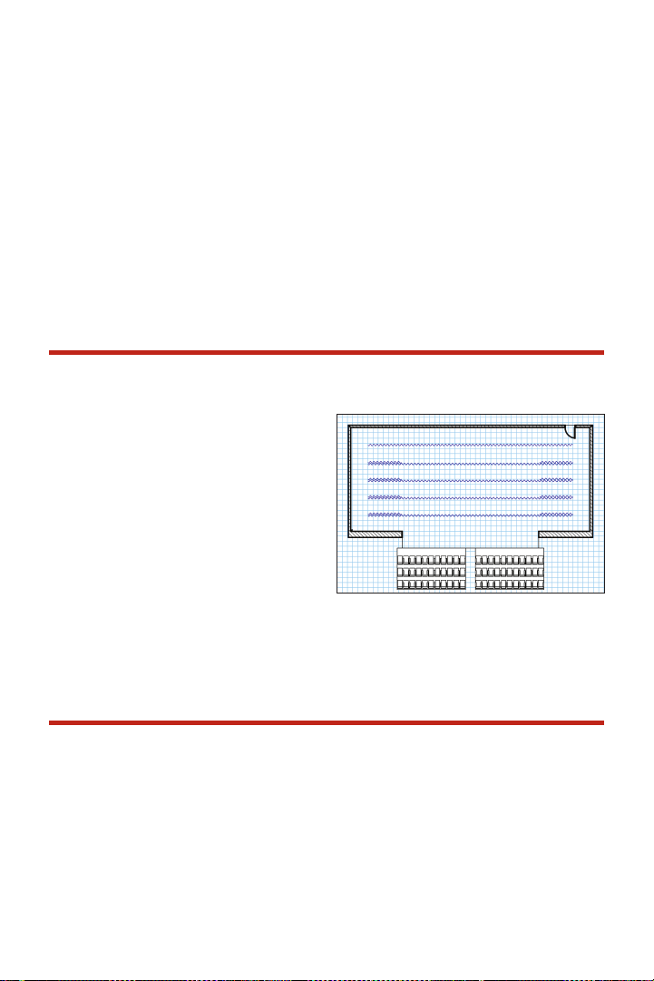
Click and drag down; hold the Shift key to
constrain the downward movement to
vertical. Release the mouse.
Duplicate the Upstage drape using the
Edit>Duplicate Array command, making
one duplicate -12” [-305m] on the Y axis. In
the OIP, change the Curtain Height of the
drape to 10’0” [3.048m], the Z value to 18’
[5.486m] and the Curtain Length to 60’
[18.288m]. Duplicate three times as you did
the legs to create full set of borders. Class
the borders.
Note that to see multiple layers using the
same view, select Unied View in the View
bar.
Create Seating Layout
You now have a fairly complete and
well-masked stage house. Let’s add seats.
Draw a rectangle from the midpoint of the
DS edge of the stage (draw from CL to SR)
20’ [6.096m] wide by 12’ long [3.658m],
select it, and go to Modify>Move>Move
and move -2’ [-.610m] on the X axis.
With this rectangle selected, go to
Spotlight>Architectural>Create Seating
Layout. Select the Padded Theatre Seat
and click OK. When prompted, select the
focus straight ahead, and seats are
automatically created. Congure the
arrangement in the OIP.
Curved Wall Tool
On the Scenery Layer, select the Round
Wall tool from the Building Shell tool set.
Click on the Preferences and set the width
of the wall to 4’ [1.219m], and select the Left
Control Line. Draw from the center of the
stage, click and drag straight down. Tab into
the FDB and enter 4’ and 90 degrees. Draw
an arc that is 270° so that the arc ends
facing your audience. Set the height to 42”
in the OIP.
Vectorworks Spotlight 2011 Getting St arted G uide | 45
Page 48
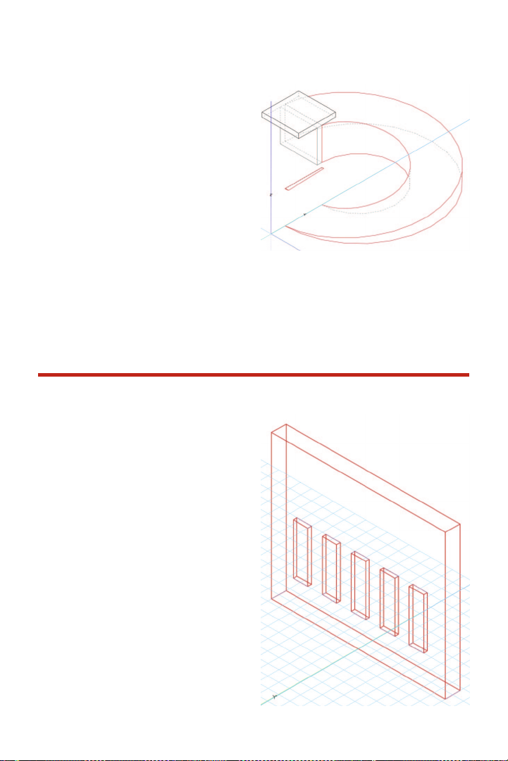
Edit the wall with the 3D Reshape tool from
the 3D Modeling tool set. Switch to the Left
View and grab the DS edge of the wall; drag
it to the ground, changing the wall to a ramp.
This basic editing procedure, which works in
much the same manner as using the 2D
Reshape tool on a planar object allows the
creating of angled or gabled roof lines on
any wall object.
From the midpoint of the wall face that is
parallel to the plaster line, draw a 6”
[152.40mm] by 48” [1.219m] rectangle.
Extrude to 4’ [1.219m] and from the DS
midpoint of this object draw a 4’ [1.219m] by
Wall Sculpting
Draw a 2’ [.610m] deep by 24’ [7.315m] wide
by 20’ [6.096m] tall, 21’ [6.401m] Upstage of
the Plaster Line. This is a bit boring, so we’ll
add a few niches. On the midpoint, center a
rectangle 1’ [.305m] deep by 2’ [.610m]
wide. Extrude to 7’ [2.134m] and set the
bottom Z to 4’ [1.219m] in the OIP. Duplicate
two of these elements -4’ [-1.219m] on the Z
axis and two also 4’ [1.219m] on the Z axis.
Select all of the elements and the wall. Go
to Spotlight>Architectural>Create Wall
Recess and accept the defaults.
4’ [1.219m] rectangle. Extrude the last
rectangle to 6” [152.40mm], and change its
bottom Z to 4’ [1.219m] in the OIP.
Note: You can also add wall projections if you
like. The process is very much the same.
46 | Vectorworks Spotlight 2011 Getting St arted G uide
Page 49

In almost every case here, we have used
the default settings. It is critical that you go
back and experiment with other settings to
see how they affect your choices and
possibilities. Experimentation and
observation is the only way that a new user
can master the program.
Rotated Views
Note the Rotate View icon in the View bar.
This tool allows users to change the angle of
the view of the plan such that if, for example,
the set was not parallel and perpendicular to
the Plaster Line/Center Line, the set could
be viewed at right angles.
Select the Unied View button in the View
bar for all layers to align to the new view.
Rotated Plans can be saved as Saved Views.
Vectorworks Spotlight 2011 Getting St arted G uide | 47
Page 50

Column Tools
Let’s go back to the Building Shell tool set
and select the Column tool. Insert a
column stage left in wing two. Select the
column and go to the OIP. Enter the data as
shown in the screen capture, on page 47.
Select Get Finishes/Classes in the OIP
and seat all to the class Scenery-Column.
Note: You can make precise placements with
the FDB.
Save this Theatre Project le for future
reference. When manipulated with the
Flyover tool, your work should look like the
illustration below..
48 | Vectorworks Spotlight 2011 Getting St arted G uide
Page 51

Section 5:
Understanding Symbols
Symbols are specically intended for items that repeat, but can also be used for one-off
objects. Symbols help keep a le or a project organized.
Symbols help control the size of your le. A symbol denition is stored only once in your
le. If you edit a symbol, all instances of that symbol will be updated. Data can be attached
to a symbol.
Any object can be saved as a symbol and will be stored for your access via the Resource
browser. You can then readily edit the symbol by right-clicking on the symbol in the
Resource browser.
Elements within symbols can be given classes for rendering and line weight. The symbol
itself can also be classed. In this case DO NOT CHECK the “Use at Creation” box and
assign no attributes when creating the Class for the symbol(s).
If a project has moving scenery, multiple instances of the same symbol with different classes
can represent the unit on stage and in storage.
Vectorworks Spotlight 2011 Getting St arted G uide | 49
Page 52

Symbol Geometry
2D Symbols
A 2D symbol has only 2D geometry.
3D Symbols
A 3D symbol has 3D geometry and will
display properly in all views, rendered as the
user dictates.
Hybrid Symbols
A Hybrid symbol has both 2D and 3D
geometry and displays the 3D geometry in
all views EXCEPT Top/Plan. In the Top/
Plain View a Hybrid symbol displays simple
2D shapes. Lighting Instrument symbols are
Hybrid symbols.
Available Resources
Go to your Vectorworks application directory
and look at the many libraries provided. You
can add more as Favorites so their contents
can be accessible via the Resource browser
or you can open some of these les and
then access them via the Resource
browser. In the latter case, you can
right-click on a symbol and either “Import”
or “Reference” the symbol. Note the section
about ‘File Referencing’ below.
Take some time to look through the valuable
content that Nemetschek Vectorworks has
assembled. In addition to the audio gear
and lighting equipment you will nd
furniture, hardware, and xtures that will
prove useful.
Inserting Symbols
Symbols are inserted using the 2D or 3D
Symbol Insertion tools after a symbol is
selected from the Resource Browser and
activated. Some special types of symbols
have specic insertion tools. Those other
insertion tools will be covered later.
50 | Vectorworks Spotlight 2011 Getting St arted G uide
Note: To insert symbols click once. The you can
rotate the symbol. Click a second time to lock
down the rotation. Double-click on insertion if you
do not want to rotate.
Page 53

Creating Symbols
To create a symbol, select a 2D or 3D
object or group and go to Modify>Create
Symbol. The Create Symbol dialogue
offers several options: it allows you to
select where the symbol will be inserted
and whether the symbol is scaled to the
World Base or Page Base. It also allows
you to class the inserted symbols.
World Based symbols are inserted ‘in scale’
while Page Based symbols will always
appear in the size drawn on the page, no
matter what the scale of the layer.
If you have a 3D symbol and want it to be a
Hybrid, see Editing Symbols.
Symbol Types
Plug-in objects (PIO or PIO’s) are like standard symbols, but customizable. You will see that
doors and windows are PIO’s and can be varied within a single drawing. PIO’s are modied
in the OIP or other dialogues.
Red
A “red” symbol is a symbol converted to a
PIO. Individual insertions of these symbols
can be extensively modied in the OIP.
Blue
A “blue” symbol is made when, Convert to
Group is selected when the symbol is
created. When placed, this type of symbol is
converted to an editable group. Changes
made to the symbol later have no effect on
the group.
Black
The most common type of symbol is the
“black” symbol. Changes made to the
symbol affect all instances of the symbol.
Vectorworks Spotlight 2011 Getting St arted G uide | 51
Page 54

Modifying Symbols
Symbols can be modified or replaced via the OIP. Symbols can be scaled by percentage
symmetrically or asymmetrically.
Editing Symbols
Symbols can be edited from within either the
document or the Resource browser. When
editing in the document, the objects around
the symbol are grayed out. When editing
from the Resource browser, the symbol
appears isolated. Right-clicking on a symbol
in a document shows a contextual menu that
offers the choice of editing the 2D or the 3D
component of the symbol. Right-clicking on
the symbol in the Resource browser brings
up a dialogue that allows you to edit of the
2D, the 3D, and options.
Editing works like any other drawing
modication. Note the heavy yellow-orange
border around the drawing area that
indicates you are in the Edit Symbol Mode.
Also note the Exit button in the top right of
the window.
52 | Vectorworks Spotlight 2011 Getting St arted G uide
To Create a Hybrid symbol, edit the 3D
component and copy the entire object. Exit
the 3D and edit the 2D component and
Paste in Place (Command-Option-V) the
3D element. With the 3D element still
selected, go to Modify>Convert>Convert
to Polygons, select the Hidden Line
option. In the OIP set the Plane to Screen.
Exit the Symbol.
Page 55

File Referencing
Go to Tools>Organization and open the
Organization dialogue. Select the
References tab on the far right.
References are the key to collaboration. If
one member of the team draws the studio,
theatre, or ballroom space and saves it as a
symbol, other members of the team can
“reference” that symbol. If it is modied, all
drawings associated with that reference will
be updated. Similarly, the set designer can
save the scenic elements as symbols, and as
the design is developed, all members of the
team have updated information. A scenic
studio or technical director can add structure
to the set by inserting other symbols.
Exercise
Open the TheatreProject.vwx file with your set and theatre model. Save the Back Wall and
the Column as symbols.
Vectorworks Spotlight 2011 Getting St arted G uide | 53
Page 56

Page 57

Section 6: Drawing a
Light Plot
In preparation for creating a light plot we will go through several steps that add information to
our document. Users will want to add these settings to their Default.sta document.
Open your TheatreProject.vwx le with the theatre and set model. Work on the Light Plot layer.
Label Legends
A label legend provides information around
your units. Go to Spotlight>Label Legend
Manager and select Add. Call the rst one
LL-1 for brevity. Once created, click in the left
column to make the legend active.
Select Edit Fields. For simplicity select only
three of the many possibilities: Unit Number,
Color, and (down near the bottom) Focus. To
select a data eld, just check in the left column.
Note: In the right column you can choose to
enclose information in a container.
Containers are symbols, and to change the
container, you must edit the symbol in the
Resource browser. The container symbols do not appear in your document until you choose
to use them.
Vectorworks Spotlight 2011 Getting St arted G uide | 55
Page 58

Click OK. Select Edit Layout, which will
open the Edit Symbol window, dened by
the colored border. From here you can
select and drag the labels from the left
column around the instrument. The Smart
Cursor will help you align the data. You can
also use the Align command. Text can be
formatted from the Text menu. Click Exit
Symbol when nished.
You will also want to create additional label
legends to use on vertical lighting positions;
one with the information on the right and
the other with the information on the left.
Remember once you have created your
label legends, add them to your Default.sta
document.
Label Legends will automatically size
themselves appropriately for the instruments
to which they are assigned.
Focus Point Objects
Focus Point objects serve several purposes:
• They allow the designer to verify the instrument throw and beam angle.
• They graphically illustrate where instruments will be focused.
• They indicate where the light will fall in visualization renderings.
In 3D views instruments assigned to Focus
Points aim at the Focus Point, allowing
designers to see focus issues and make
appropriate adjustments prior to installation.
The 2D portion of the symbol can be
“focused” or not, manually and independent
of the 3D portion of the symbol, even as
they occupy the same space. This allows for
technical accuracy and graphic clarity.
56 | Vectorworks Spotlight 2011 Getting St arted G uide
Go to the Spotlight tool set and select the
Focus Point tool. Click on the tool Options
in the Tool bar. There is a drop–down menu
of choices for the graphic attributes of the
Focus Point object. These options can also
be accessed from the OIP. There is a
standard hybrid symbol, a 2D, a 3D and
Locus Point. Below the dividing line there are
additional choices available from the default
Page 59

content. These choices are editable symbols,
including vertical focus objects. Users can
add their own content or modify the defaults
once imported into an active document. You
can also choose to show or hide the Focus
Point object in the Tool preferences.
For the purposes of this exercise, in the
Focus Point tool preferences select Show
Focus Point Name and choose Standard
2D from the drop–down menu. In your
Application Preferences>Display Tab, set
Display light objects and Display 3D loci
to Only in wireframe. Class the Focus
Point objects in the Focus Points Objects
class, with no graphic attributes.
In the sample Theatre Project le there are
ve areas used to create a simple
downstage wash, an area at the top of the
platform, and two areas to focus light on the
rear wall. Use the midpoint of the stage and
the Smart Cursor to set your rst area.
Duplicate Array as needed and rename the
new objects in the OIP.
Lighting Positions
Next, you will need some electrics. Go to
the Resource browser, use the drop–down
menu to access the Lighting Positions le
we already added as a favorite, and select
the 50’ pipe symbol. Right–click (control–
click on a Mac) and select Import from the
contextual menu. Revert back to the active
document in the Resource Browser by
clicking the Home icon, and then double–
click on the 50’ pipe to select it. Go to the
Spotlight tool set and choose the Light
Position Obj tool.
Vectorworks Spotlight 2011 Getting St arted G uide | 57
Page 60

Align the insertion point with the midpoint of
the DS edge of the stage, press the “T” key,
and position. Adjust the position and set the
Z height in the OIP. Name the position in the
OIP. Repeat for the onstage electrics.
Use the Vectorworks duplication options for
adding electrics.
Off–stage add two 20’ Vertical Lighting
positions on one side. For graphic clarity
they should be away from the stage.
Functionally, one will be side light focused
on the area on top of the platform and one
will be a front of house box boom side
lighting position with instruments focused on
the downstage wash.. Once populated with
lights, these positions will be duplicated with
the Mirror tool.
Creating Lighting Positions
The Vectorworks libraries are great
resources, but they cannot anticipate
everything any designer will ever need. The
application allows you to create for your
particular situation. Any hybrid symbol
inserted with the Lighting Position tool (or you
can select a hybrid symbol and go to
Spotlight>Object Conversion>Convert to
Lighting Position) can be a lighting position.
You can easily create a lighting position with
the Truss tools or with simple primitives.
The Truss tools are pretty self explanatory
at this point: they create hybrid objects. A
library of commercially available truss
included with the package.
While a lighting pipe is typically round, you
can choose to make it a square (simpler
geometry, smaller le size) extrusion 2”
[50.80mm] by 2” [50.80mm] by your choice
of length. You will likely want to assign a
class to the 3D element. Make sure that
your 3D component is centered at 0-0 and
Modify>Create Symbol, with the insertion
point at center. Name the symbol, click OK
and then right–click on the symbol in the
Resource Browser to edit the 2D
component, which currently does not exist.
There are two schools of thought on the 2D
component–line or rectangle. The decision
is up to you. In either event, double–click on
the 2D tool you need and place the object–
the same size as the 3D (in the case of the
line, the same length)–at the 0-0 point.
Class the new object, and exit the symbol.
You now have a hybrid symbol that can be
used as a lighting position.
58 | Vectorworks Spotlight 2011 Getting St arted G uide
Page 61

Trusses
The Truss tools in the Spotlight tool set can
be used as Lighting Positions. The Straight
and Curved Truss tools should be self–
explanatory to you by now. They insert
hybrid objects. You can specify sizes to
create either custom trusses or objects that
match trusses you know you will be using.
There are truss symbols for many
manufacturers in the Entertainment Library.
If you are using trusses, draw the elements
you need, select them and choose
Spotlight>Object Conversion>Convert to
Lighting Position.
Inserting/Modifying Instruments
Double–click on the 26° instrument symbol in the Resource browser. Notice that the
Instrument Insertion tool has been activated. Place the rst instrument on the FOH position
at center. Look at the OIP and notice the number of options available. Double–click on the
Lighting Device or click the Edit button on the OIP. Select a focus for the unit. On the Light
Information tab, select Draw Beam. Click OK. Notice that Vectorworks Spotlight calculates
the angle and coverage of the instrument. You can use this feature to verify your instrument
choice. Don’t forget to deselect Draw Beam from the OIP, or your drawing will become very
cluttered, and selections will be very unwieldy.
Coloring Lights
From either the Lighting Device dialog box or
the OIP, you can assign Rosco, Lee, or GAM
color in the color eld. A Rosco color is
noted as R36 and a Lee as L36. Hexidecimal
or RGB values can also be entered.
You can add additional information to your
schedule. When you add color and focus
in the OIP, that information will appear in
the LL-1 label legend in Top/Plan view on
the plot.
Also note that the instrument added now
appears in the Visualization palette. Double-
clicking on the instrument in the Visualization
palette selects that unit on the plot.
Vectorworks Spotlight 2011 Getting St arted G uide | 59
Page 62

Editing Lights
Lights can be edited and focused in a
variety of ways. We’ve already looked at the
powerful OIP and have seen how that
design control point interfaces between your
lights, focus objects, positions, and label
legends. Let’s look at other options.
Right–clicking on the instrument in the
Visualization palette allows editing of the
lighting properties.
Double–clicking on the instrument in the
plot allows editing of various properties,
including shutter cuts for visualization.
Right-clicking on a unit offers several
choices: Edit, Edit Light and Properties in the
contextual menu. Edit opens the Lighting
Device dialogue. Edit Light accesses the
dialogue at right, reaching into the symbol to
access the Vectorworks light source (more
on those a little later). Properties is another
route into the OIP data.
Use the Instrument Insertion tool and
Duplicate Array command to add additional
instruments. Add information as you need in
the OIP. Once you have populated an
electric, select the position and check “Auto
Number” in the OIP; the instruments will be
numbered and that information will be
added to the plot. If you move units around,
deselect and reselect Auto
Number, and the information will be updated
on the plot.
Before we can present and visualize this
light plot, go to Spotlight>Reports>
Generate Paperwork. Select the schedules
you need, for example, select Instrument
Schedule and click Setup to specify what to
include in the schedule. Schedules will be
stored in the Resource browser.
Adding Accessories
Instruments often need accessories like
color scrollers, or barn doors. There is a
selection of accessories in the Vectorworks
Entertainment Library. You can also make
accessories symbols by creating a hybrid
symbol, selecting it, and going to Spotlight>
60 | Vectorworks Spotlight 2011 Getting St arted G uide
Page 63

Object Conversion> Convert to
Accessory. Selecting an accessory symbol
activates the Accessory Insertion tool.
Inserting accessories is a three-click
operation. The rst click inserts the
accessory, the second click sets the angle.
The cursor provides highlighting for the third
click. Clicking on an instrument in place
associates the accessory with an instrument.
Adding Gobos
Vectorworks comes with a large library of
gobos by many manufacturers. You can
easily import a gobo texture into your
document or create a custom black–and–
white or full–color gobo.
Any square graphic image can be imported
into Vectorworks as a gobo texture. Go to
Spotlight>Visualization>Create Gobo
Texture and follow the steps through the
creation of the texture. Name the gobo.
We’ll look at creating textures in more depth
shortly, simply accept the defaults.
Remember that the gobo projection is only
going to the image within a circle within your
square image.
Alternately, via your Resource browser, you
can open or add as a favorite one or more
of the stock gobo libraries and import a
gobo texture. Once you have your texture(s)
in place, you can add one or two gobos to
any instrument in the OIP. You can see in
the OIP that you can also rotate the gobo
images as needed for visualization.
Shutter Cuts for Visualization
Double–click on an instrument in your plot
and open the Lighting Device dialogue. The
right–hand tab will be for shutters. This
dialogue simple and easy to understand. It
is very interactive. You will need to check
your work as you go by rendering with the
single light activated.
Aligning Instruments
Although it is possible to Align/Distribute
lighting instruments with the Modify>Align
commands, the Spotlight Align tool provides
additional entertainment industry–specic
options.
Select multiple instruments and select the
Align tool from the Spotlight tool set. As
indicated in the Tool bar, draw a line to align
the insertion points of the instruments. Once
the line is drawn, you will see the associated
dialogue that allows alignment or alignment
plus distribution–including distributing on
instrument centers.
Vectorworks Spotlight 2011 Getting St arted G uide | 61
Page 64

Ganging Instruments
Instruments can be ganged by channel,
dimmer, or circuit as specied in the tool
Preferences. Once the ganging method is
selected and the tool is active, click on two
or more instruments and then once in
space to gang the units. Clicking above the
units places the ganging graphic above,
clicking below places the gang indication
under the instruments.
If you gang three instruments and need to
revise the ganging to two units ganged
adjacently, simply select and delete the
ganging graphic that attaches any two of
the units.
Vertical Lighting Positions
We are not drawing this plot for production,
but rather to illustrate how all these tools
work, individually and together. In production
other and/or different elds would be required,
but the principles remain the same.
Place a 20’ [6.096m] pipe outside of the
theatre architecture. Populate the position
with a few lights. Begin with one unit to the
right of the position. Assign the unit to the
position and give it a color and Label Legend.
Duplicate the light down the pipe and Mirror
the units. Now Mirror the entire position to the
opposite side of the stage. Reassign and
adjust the Label Legend information. Name
the position and assign the lights to the
position.
62 | Vectorworks Spotlight 2011 Getting St arted G uide
Page 65

Projection/Monitor Tools
Vectorworks includes a number of very useful
tools if you will be working with projections
onstage, in television, trade shows, or
corporate theatre. In the Spotlight tool set,
take note of the Television tool and the two
Projection Screen tools–plain and blended.
These tools work very much like many
others covered. Take some time and explore
them in a new le. Note that once inserted,
you can change the size of the monitors/
screens in the OIP. Note that the screens
show you projector placement. The
projection cones appear in 3D so that you
can analyze any obstruction issues on the
computer and not in the eld.
Photometrics/PhotoGrid
The Photometrics and Photogrid tools
provide you with two ways of ensuring that
you have an even wash and that your focus
areas are not spread too thin. If you are
working on a television production,
Vectorworks uses these two tools for
measuring the light from your instruments.
The Photometer tool in the Spotlight tool set
measures the elevation and light at any
given point on the stage. Draw Beam must
be turned on for this tool to work. Simply
select the tool and insert on the plot. As you
turn Draw Beam on and off for different
units or systems, you will have to refresh the
Photometer Object.
The Photometer Grid tool allows you to
create an array of photometers across the
stage–perhaps one at the center of each
area and one where each area overlaps
with the next.
Vectorworks Spotlight 2011 Getting St arted G uide | 63
Page 66

Basic Scripting
Don’t let scripting scare you. We can start
with is a simple macro. You might want to
create more. Let’s say that you want to
change all of the R37 in this plot to another
color. That sounds pretty tedious, even if we
don’t have many instruments.
Go to Tools>Custom Selection. Choose
Select and Create Script and then click
Criteria. Set the criteria as illustrated. Note
all of the options. This is a technique that
can be used for many things. Once you
have all these units selected, you can change
the color in every one with one keystroke
in the OIP.
Once you save the script, you will have a new
“Scripts” window. To execute the script,
double–click on the name.
To change another color, the script is stored
in the Resource browser. Open the Scripts
folder, right–click on the script in question,
and select edit from the contextual menu.
Simply change the color number and save.
The script is ready to run in the script window.
If you close your script window, you can
always get it back at Window>Script
palettes>Scripts.
64 | Vectorworks Spotlight 2011 Getting St arted G uide
Page 67

Custom Lighting Symbols
Any Hybrid symbol can be made into a
Lighting symbol by selecting the symbol in
the document and going to Spotlight>
Object Conversion>Convert To
Instrument. In this way, you can assign a
symbol to represent a practical or prop lamp
and be accounted for in your paperwork.
The next section details Vectorworks lights.
Once you review that section, you can come
back, edit your 3D symbol, and insert a light.
If you are looking to represent a specic
lamp type, Vectorworks has a le of lamps
in the library, which you should have already
added to your Resource browser favorites.
You can also import Illumination
Engineering Society (IES) data from
manufacturers specications.
Be sure that your symbol either uses the
default instrument texture or a texture with
cast shadows unchecked for the light to
pass out of the instrument.
Create Plot and Model View
The Create Plot and Model View command
will create a Denition Layer for the boom(s)
selected. From that Denition Layer it
places a Design Layer Viewport (DLVP) of
the boom(s) in plan on the Plot Layer–this is
your 2D Light Plot View. It will also place a
DLVP of the Denition Layer on a new or
existing Model Layer. The Model Layer
(after you have rotated the booms) is used
for stage sections and rendering.
Critical issues:
• You must have a layer structure as I
have previously described.
• Your lights and positions must be on
one layer.
• If your focus objects are on the layer
with your lights and positions, they should
be classed together and invisible.
• Be sure that you do not have any
Sheet Layer Viewports created that
reference the Plot Layer.
Select one of the vertical positions and
associated units. Go to
Spotlight>Visualization>Create Plot and
Model View.
Vectorworks Spotlight 2011 Getting St arted G uide | 65
Page 68
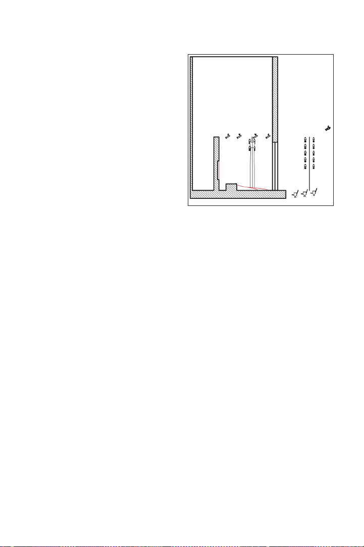
The Create Plot and Model View command
moves the selected lights and lighting
positions to a new design layer and
references them back to your Plot Layer as
a Design Layer View Port (DLVP). Create
Plot and Model also places a DLVP on an
existing model layer, or it will create a new
model layer.
The rst dialogue in the process names the
new Denition Layer. Since we have two
vertical positions, we will run this command
twice. Name each Denition Layer so you
can identify your positions. Check the box
next to Vertical.
If you have multiple boom positions, you must
run Plot and Model View for each boom, or
create the booms on layers separate from
your horizontal hanging positions.
If you include your horizontal positions or
have nothing selected when you run the
Create Plot and Model Command, all or
none of your positions will become vertical
positions.
Denition layers are created at the same
scale as the original layer. Objects are
placed at the same position as they were
originally drawn. When viewing the Model or
the Plot Layer, be sure to turn off all the
visibility of the Denition Layers.
On the Model Layer you can rotate and
position the booms so that they will appear
correctly in sections and elevations using
the 3D Selection tool in the Basic tool set or
use Modify>Rotate>Rotate 3D.
In your Model Layer, in the Top/Plan View,
select a boom and rotate so it faces the
stage. Repeat, as required for each vertical
position.
If you create each position manually Create
Plot & Model will create another Denition
Layer and DLVP that contains all the other
geometry–It just won’t rotate that way all you
have on your plot and model layer are DLVPs.
If you view your Plot Layer and Model Layer,
you are going to see the DLVP on the Plot
Layer and the DLVP on the Model Layer.
Use the visibilities options in the Navigation
palette to make your choices.
66 | Vectorworks Spotlight 2011 Getting St arted G uide
Page 69

When we create Viewports to present the
drawings, you will:
• Make a Top/Plan Viewport of the Plot
Layer, with other appropriate layers visible.
• Cut Section Viewports of the Model
Layer using View >Unied View and with
other layers visible as required/desired.
• Use the Model View, Camera tool,
Unied View, and other layers to render and
visualize the design and/or specic cues.
In the annotations space of your Plot
Viewport, you will want to add a 2D symbol
indicating boom placement. The 3D View of
the instruments shows the 3D and you will
want the 2D symbol for graphic clarity.
I have also rendered this simple design that
you see above, set some light levels, turned
some instruments off, added some lights as
I felt necessary in the visualization phase,
and added gobos. We have reviewed all of
those steps or we will review them as we
move forward, but you should make your
own design choices. All of these les, like
this plot, are relatively simple, but your work
will likely be much more complicated.
Vectorworks Spotlight 2011 Getting St arted G uide | 67
Page 70

Paperwork
Transferring Data to and
from Lightwright
At the beginning of this guide, we looked at
File>Document Settings>Spotlight
Preferences and the Lightwright Tab. This
Preference tab allows users to determine
what information about lighting units they
would like to be able to export to
Lightwright in order to create paperwork for
executing the lighting design.
The exchange of information between
Lightwright and Vectorworks is automatic.
Check the box for “Use automatic Lightwright Exchange” to enable this function.
Vectorworks Reports
Vectorworks can also generate instrument
schedules, hook-ups and other paperwork.
Go to Spotlight>Reports>Generate
Exercise
Paperwork. Follow the directions, and make
your choices. We’ll set that up for printing in
the Presenting Your Design section.
Working in your Theatre Project le:
• Add classes for your lights, lighting positions and focus objects.
• Create on stage and Front of House electrics and populate them with lights
• Create a minimum of four boom positions with lights.
• Focus and color the lights.
• Create a Plot and Model View of your work.
68 | Vectorworks Spotlight 2011 Getting St arted G uide
Page 71

Section 7: Visualizing
Your Design
The image below has some classes added, additional lights, and gobos inserted, and textures
created. It could illustrate one moment of one cue. Many such views can be created by set and
lighting designers to convey their ideas to directors, producers, colleagues, and craftspeople.
The rendering and visualization capabilities of the Vectorworks Renderworks module are
key to the creation of an efcient workow. In a proper workow, the ability to update a
model and have all of the mechanical drawings and renderings updated is critical to a
smooth operation. Having all of these functions within one suite that communicates internally
has proven to be the only path.
Vectorworks and Renderworks provide a number of ways to visualize your drawings. Some
of these are pertinent to presenting your mechanical or designer drawings; others are
relevant to visualization. Combining these methods also allows designers to include
illustrations within the mechanical drawings.
Vectorworks Spotlight 2011 Getting St arted G uide | 69
Page 72

Renderworks and Spotlight allow lighting
designers to visualize moments and cues and
present them to colleagues before working in
the theatre. Using the lighting controls and
renderings, designers can write cues well
before tech. Time invested in the design studio can save producers valuable crew time.
For lm or television the Camera tool can
show specic lens choices and camera
placement views of sets. While we will not
deal with the animation tools, or third-party
animation plug-ins, Vectorworks makes it
easy to illustrate camera moves or walk
through animations of exhibit spaces or
themed environments.
It is very important that renderings and
models clearly show clients and colleagues
the design intent. Clients do not like sur-
prises. Renderworks allows designers to be
very specic about what the deliverables will
look like, well before fabrication. Changes
made in the 3D space and renderings are
much more easily changed than built pieces.
Textures (sometimes also referred to as
Materials) are some of the real magic within
Renderworks. Learning to use them well will
help create effective presentations. You
cannot get to the point of building your ideas
if you cannot effectively show your vision to
others.
This book is all about the application, but I
would be remiss not to say this text ignores
the paper-and-pencil process that should
take place as you think and plan.
Rendering Modes
From the drop-down menu in the View bar or by going to View>Rendering you will see a list
of available rendering modes. The View menu list is longer, so let’s look at it;
• Dashed Hidden Line
• Line Render Options
• Unshaded Polygons
• Shaded Polygons
• Shaded Polygons No Lines
• Final Shaded Polygons
• Create Batch Render Job
• Start Batch Render
• Wireframe
• Wireframe Options
• Sketch
• Sketch Options
• Open GL
• Open GL Options
• Fast Renderworks
• Final Quality Renderworks
• Custom Renderworks
• Custom Renderworks Options
• Artistic Renderworks
• Artistic Renderworks Options
• Hidden Line
70 | Vectorworks Spotlight 2011 Getting St arted G uide
Page 73

This book will not delve into every option.
First, let’s consider at a few things related to
line drawings.
We have been working in the Wireframe
mode, which shows every line we’ve drawn.
However, if you want to show an elevation
without clutter, this is not the appropriate
mode to use. Consider thinking back to
hand–drafting conventions, and that Hidden
Line or Dashed Hidden Line might help to
clarify our intent. Use and experiment with
the Line Render Options dialogue to adjust
the look of the rendering mode.
When rendering, you will want to move from
an orthogonal or isometric view into a less
mechanical perspective view. Go to View>
Projection> Perspective.
Open GL renderings are useful for fast
preview images to see if your textures are in
place and properly oriented. Open GL is not
a presentation format. Open GL can be
useful for your own visualization. Open GL
does not render backgrounds.
We will focus on Final Quality Renderworks,
which offers a great look for presentations.
To save time as you develop ideas, consider
rendering in Fast Renderworks to preview
your ideas.
Open GL and Renderworks each place an
unseen light source in your renderings if you
have not already ‘lit’ the scene. Since we will
deal with lighting specics next, just work
with that invisible light source for the moment.
Layer Backgrounds
In our theatre space, we do not need a
background, as we have the architecture.
However, if illustrating an isolated element,
like the Martini Glass or a trade show space,
you might not want to model an entire world
before you render a simple object. In these
cases,
Renderworks defaults to a white background
that you can easily change.
Work in the le you created when you made
the ten–3D objects.
Vectorworks Spotlight 2011 Getting St arted G uide | 71
Page 74

Choose to edit your design layer via either
the Navigation palette or the Organization
dialogue. Using your existing le, you now
have the opportunity to create ten different
backgrounds. First, note that in the Edit
Design Layer dialogue you can assign a
background from the default backgrounds
le. Once we create a few backgrounds, you
can also assign a background to a layer by
double–clicking on the background icon in
the Resource browser.
Let’s make a few backgrounds. Exit out of
any dialogues and go to the Resource
browser, right–click and select New
Resource>New Renderworks
Background.
After taking a look at your options, name
your background something that will readily
remind you of the content. You also have
weather options, which we will avoid right
now, as they add considerably to the
rendering time. For the moment, be aware
of the options and plan to go back and test
them. Your test le is a good place for this
kind of experimentation, as you currently
have minimal geometry to slow the process.
The top drop–down will be our focus:
• Clouds
• One Color
• Two Colo r
• Image
• Image (HDRI)
One Color should be self–explanatory and
having at least a black background is always
useful. When roughing out ideas, use a black
background rather than worrying about the
surrounding architecture. Two colors will give
you a traditional gradient background.
The Clouds option is very versatile, certainly
useful if you are doing an outdoor project or
if you want to see a simple outdoor scene
behind a set. Clouds also make terric
backdrops for free–standing kiosks. The
default options make for a lovely day sky.
Switching the default white to black, gives
you a good night sky. As always, you need
to experiment with the options and render
the options in Final Quality Renderworks to
see your results.
Select Image>Options brings you to a
standard OS File Open dialogue–select an
image that you would like to use as a
background–say a park or beach scene.
That selection takes you to the Edit Image
Background dialogue. The size of the image
will be based on the size of your output, so
there should be no surprises. But what are
Flip H and Flip V? Instead of the X and Y
indicators we have used elsewhere,
Vectorworks has changed the designation in
this dialogue to horizontal and vertical.
Images can be inverted– made to look like a
lm negative image–consider that for some
types of presentations you might want to
make a Vectorworks drawing or a hand–
drafting into an old–style blueprint with
white lines on blue or black.
72 | Vectorworks Spotlight 2011 Getting St arted G uide
Page 75

Simply dened, High Dynamic Range
Images (HDRI) contain lighting data and are
a composite of different exposures that
Vectorworks can use to “light” a scene. So,
if you’re working on an outdoor project and
have (or can create) an HDRI image of the
area at a certain time of day, the light data
contained in the image and interpreted by
Vectorworks will cause your model to be lit
with the same colors and angles as the
background. There are many resources on
the Web from which you can download
HDRI images. Be sure to verify the licensing
and ownership of those images.
Exercise
Make at least ten backgrounds for use later.
Understand that you should allow time to
edit and modify those backgrounds as you
work with them to take your document to the
next stage.
Create a Black Background for your Theatre
Project and assign the background to the
Theatre Architecture Layer.
Textures
Vectorworks provides a large number of predened textures. As always, you’ll nd them, if you
haven’t already, in the Libraries. While you can use the library textures, it is also useful to
review them to see how they have been created. Use this study as the basis for the creation
of your own textures.
Creating Textures
You can create a new texture the same way
you create a new Renderworks Background.
Right–click in the Resource browser and
select New Resource>New Renderworks
Texture. Note that in both cases, once you
have a background or texture created, you
can right–click under the sub head to
access the “new” choice.
In the Create Texture Dialogue–accessible
by right-clicking in the Resource Browser–
there are several overall options:
• CThe size eld in the lower left
denes the size of your texture.
• CThe Indirect Lighting Options button
in the lower right allows you to create
glowing or back lit objects by overriding
document lighting.
Textures can generally be described as
either a Procedural texture or an Image
Based texture.
Vectorworks Spotlight 2011 Getting St arted G uide | 73
Page 76

Procedural
A procedural texture is computer generated
using an algorithm designed to produce a
realistic representation of natural elements
such as wood, metal, stone, and others.
Image Based
An image based texture has as its primary
source an image le, such as a JPEG or
PSD le. A logical use for an image based
texture would be to illustrate a painted back
drop on stage. Image based textures can
also represent commercially available
products like carpets or patterned plastic
laminates.
Images created for use as image based
textures can be designed in one of two ways:
‘To be a seamlessly repeating pattern.
• To be dened in actual size.
Images as textures should be kept to a
moderate size. As a very general rule, no
larger than a 1Mb le. The image les
should be created with the output method in
mind. This concept is discussed in further
detail in the section on Image Props.
74 | Vectorworks Spotlight 2011 Getting St arted G uide
Page 77

Shaders
Textures are dened in Renderworks by adjusting and modifying a series of denitions
called Shaders
Color
The Color Shader denes the surface color;
this can be a plain, uniform color, or a
complex pattern like wood or stone.
Object Attribute. Object Attribute assigns
the object’s ll color attribute to apply as a
color texture.
Image. Allows importing of image les.
Color. -Basic, simple color dened through
the available Vectorworks Libraries or the
system color picker. This Shader also allows
for the brightness of the color to be modied.
Fresnel. Creates a simple texture that
has an overall glowing or gradient like
appearance.
Bricks. Creates a basic brick pattern
based on percentages/proportions of the
texture size as dened in the lower left of
the dialogue. Color nd size/proportional
variants are also assigned to further rene
the texture.
Noise. The Noise shader allows access
to a huge array of options for creating
different painting or natural stone, marble,
or granite looks.
Pavement. The Pavement shader creates
colored stone patterns and textures. The
settings dened in the shader Options help
to create realistic and random repeats.
Tiles. The Tiles shader allows for the
creation of a number of different geometric
patterns. The settings in the Options allow
for a very regular pattern or a repeat that
appears much more random.
Reectivity
The Reectivity Shader denes the amount
of light reected by a surface Reectivity is
dependent on surface texture properties
and light sources
Note: Increasing the blur of the reectivity
shaders increases realism and, in turn, increases
render times.
Image. Image reectivity allows a designer
to choose what exactly will be seen as the
reection in a texture. The reection will be
an imported image le.
Back-lit. Back–lit reectivity will help to
properly render things like televisions
screens. Deselect Cast Shadows in the Edit
Texture dialog box when using the backlit
shader.
Vectorworks Spotlight 2011 Getting St arted G uide | 75
Page 78

Glass. Glass reectivity would be
appropriate for rendering windows, and
adjusting the color options of the shader
further denes environmental reections.
Glow. Glow reectivity can create objects
that do not have shadows cast across,
similar to a back-lit object that also emits
light (if the Emit option is invoked). Glow
shaders can be an alternative to creating
line or area lights.
Metallic. Metallic reectivity options can
be used to create realistic metal textures
that reect the colors in the surrounding
environment. Mirror can also be used to
create polished metal looks.
Mirror. Mirror reectivity options can create
fully reective surfaces or be used at low
settings to add a sheen to surfaces.
Plastic. Plastic reectivity options provide
designers with a subtler set of options than
the Metallic or Mirror options.
Bricks, Noise, Pavement, and Tile. These
options work with the Color Shader or be
used to overlay a reectivity onto a Shader.
Transparency
The Transparency Shader denes surface
transparency or opacity.
Image Mask. The Image Mask denes an
imported image or alpha channel as pattern
or mask.
Image. Selects an imported image to apply
as a transparency texture, for colored
transparency and projected colored lights
like gobo projections.
Color. Allows the designer the option of
isolating a color from an image based
shader to drop out of the texture.
Glass. Transparency with the options
required to properly illustrate how glass
interacts with the world around. Generally,
for glass, set the color to white, and the
Index of Refraction to 1.
76 | Vectorworks Spotlight 2011 Getting St arted G uide
Plain. A simple slider to create different
degrees of uniform transparency.
Page 79

Rectangular Mask. Uses the texture size
as a rectangular, transparent mask (usually
combined with another shader for a specic
effect). Used for decals.
Bricks, Noise, Pavement and Tiles.
These options combined with the Color
Shader overlay a transparency effect onto
a color shader.
Bump
Bump maps dene surface irregularities that
bring dimension to textures without the
complexity of additional modeling. This is an
instance where vector data would create a
larger le than a raster adjustment. Proper
use of Bump maps will produce les that
render faster than fully–modeled images.
Image. An image based bump map
species an imported image to be used
as the source of the displacement. The
image can be either a full–size image or a
seamlessly tiling image gray scale image.
Bricks, Noise, Pavement and Tiles. These
options can work with the Color Shader or
be layered onto a Color Shader for effect.
For example, the Brick bump used with the
Brick Color can create a very realistic 3D
brick, without modeling each object.
Alternately, for example, a noise bump
added to a plain color can add a stucco
effect to a simple color.
In a gray scale image, the darker areas will
appear to recess and the lighter or white
areas of the image will seem to actually
bump out.
Vectorworks Spotlight 2011 Getting St arted G uide | 77
Page 80

Textures for the Theatre Project
We will examine some the of the effects
shaders can make by creating or modifying
textures to be used in our Theatre Project.
Open the Theatre Project le.
Edit the class Scenery-Wall. Select the
texture Brick Runbond Red 02 from the
Default Texture le as the texture for all
sides of the wall. By clicking to the right of
the texture preview you can visually access
all of the textures in your document and the
Default Textures.
Click OK.
Right–Click on the Brick Runbond Red 02
Texture in the Resource browser to edit the
texture. Add a Brick Bump Map to the
textures. Set the strength of the bump to
500 and otherwise, accept the defaults.
Note in the preview that the texture is not
aligned with the image of the bricks. Edit the
Color Shader and ip the Image vertically to
align the color and bump shaders.
Create a new texture named Red Paint.
Select Edit. Click on the color swatch.
Select “Pick a Color” on the top middle right.
Select the Benjamin Moore Color Preview
palette and select BM 2000-10 Red as your
color. Click OK back to the edit texture
dialogue. Assign a plastic reectivity to
simulate a semi-gloss nish.
78 | Vectorworks Spotlight 2011 Getting St arted G uide
Create a black-matte texture in the same
way, with Reectivity set to none.
Page 81

Create a black-gloss texture by selecting
the Fresnel Color Shader and setting the
options with two shades of color (dark on
the edges), and Glass Reectivity with edge
color around 50% gray, center very dark but
not black.
Lastly, create a brushed–metal texture with
a simple color and Metallic Reectivity. Set
Assigning Textures
the Metallic Option to Brushed.
Use Class Denitions to make the theatre
walls and the drapery Matte Black, the Stage
Floor—Gloss Black, and the ramp Gloss
Black with metallic facing. The column should
be the Brushed Metal. The vertical form at
the front of the ramp should be metallic and
the top level platform should be Gloss Black.
Textures can be assigned to objects in a
variety of ways: by Class denition, by
selecting an object in the OIP, going to the
Render tab and assigning a texture from the
drop–down menu (which accesses the
default textures as well as textures in the
document), and by selecting an object and
then double–clicking on a texture in the
Resource browser or dragging the texture
icon from the Resource Browser on top of
the selected object.
It is extremely important to develop the habit
of using Classes to dene the graphic
attributes within your documents. By
extension, this means you must plan your
documents ahead of developing designs.
Notice in your Class denitions, textures are
assigned differently to walls, roofs and other
objects.
Vectorworks Spotlight 2011 Getting St arted G uide | 79
Page 82

Textures and Walls
Now that you have some textures, let’s add
them to some Classes. Open the Class tab
in the Organization dialogue. You must have
Use at Creation checked and Use Textures
at Creation checked. You will see that you
can have different textures for different sides
of walls and roof objects. All other modeled
objects are textured as Other.
Textures in the OIP
Once you have textured an object by class,
select the object and look in the Render tab
of the OIP. You now have many options,
including over ruling the class assignment.
The OIP allows for many options with scale
and placement of textures. You can also
select different texture options for different
faces of objects, just as you can texture
different wall surfaces differently.
Select the Stage Floor and change the
sides to the Red Paint Texture in the
Render tab of the OIP.
Mapping
Sphere, Cylinder, Plane, Perimeter or Roof mapping types are used to control how a texture
is projected onto different types of objects. The Attribute Mapping tool does not modify
Perimeter or auto-aligned Planar mapping types.
Attribute Mapping Tool
Find the Attribute Mapping tool in the
Visualization tool set. The Attribute Mapping
tool allows you to edit texture mapping
parameters of wrapped color shaders or
mask transparency shaders visually. We’ll
use this tool with a Decal.
80 | Vectorworks Spotlight 2011 Getting St arted G uide
Exercise
Open your le where you created the 3D
objects. Create textures for each object and
assign by class.
Page 83

Creating Image Props
Image Props are largely a task for
image-editing software. They serve multiple
purposes, but are key to adding people/
gures to renderings. You can use the same
technique for trees and small objects that
would be too complex to model or consume
too much memory, like a toaster on a
counter. Vectorworks ships with a number of
great Image Props in the Library for you to
use. If you have the Designer package or
Landmark module, you will nd a number of
additional tree Image Props in your Library
and I also suggest investigating VBvisual
Plant tool in the Visualization tool set
available in the Landmark module. The
VBvisual Plant tool requires Renderworks.
Keep your image le small, as larger
graphics les can cause Renderworks to
work slowly.
In print graphics, les are usually created at
the size they need to be printed by 300 DPI.
You will more likely be using a desktop ink jet
printer which works well with 100-150 DPI.
We’ll actually be working with pixels, not
DPI; 300 DPI x 3” tall is 900 pixels.
Vectorworks Spotlight 2011 Getting St arted G uide | 81
Page 84

How big is your person going to be when
printed? If you will only be outputting to a
letter–size page, your person may end up
as only an inch or two tall.
Create gures as “actual size” in the photo
editor. A 6’ tall man can still be a 6’ tall
image le but, set the DPI very low, usually
5-20 DPI, to keep the le size as small as
possible. Determine the DPI by estimating
how large the gure will be in the
presentation. If it will be 2” tall, you need a
le that is 300 DPI or 300 pixels tall. Set the
pixel height/DPI appropriately.
Although, as you will see, you can make
some of these specications within
Vectorworks, I nd this method cuts down on
the a possibility of error. Generally speaking,
I try to keep most image les under 1Mb.
When making an Image Prop, Vectorworks
allows you to mask out the background in a
couple of ways. Again, this is often a chore
best tackled in an image editor.
In Photoshop and Corel Painter you can
create an image mask or alpha channel that
Vectorworks can nd and use as a mask.
Alternately, you can add a solid color around
the gure and mask that color. In both cases
be aware that there are two caveats:
• Be sure that masking color is also not
on the gure or you will have holes in your
people.
• Consider the color against which you
are going to place the gure.
If you have a dark brown set and you mask
out your gure using white, most image
editors will “anti-alias” the edge. That is they
don’t just paint white, but they blend the
white into the adjacent color–your gure. So
if you mask with white and place in a dark
environment, your gure may have a white
or light gray outline. Mask your gure in a
color close to the background.
Create an Image Prop from the le included
and place the gure on stage. Class the
gure as Entourage-3D
82 | Vectorworks Spotlight 2011 Getting St arted G uide
Page 85

Decals
Decals allow multiple textures to be applied
to a single object. Decals are created in the
same manner as Image Props or Textures
with a mask. Adding a decal allows you to
either create a new decal or use one that
you have created and is residing as a
Texture in the Resource Browser. Decals
are great for adding grafti to a wall, a logo
to a set, or a carpet on a wood oor.
Import the Grafti texture from the le
provided. Edit the Stage Wall symbol in 3D.
View your wall, full screen in an isometric
Unied View
The Unied View command in the View
bar has been mentioned before, but since
it is critical to the information that follows,
let’s spend a little more time discussing
this functionality.
In a document with several layers, like the
set and lighting design we are working with
right now, it is likely that you will need to
look at multiple layers at once and you will
want to switch between views. Simply
switching views only affects the active layer
unless Unied View is activated.
view, render in Final Quality Renderworks.
Select the wall and go to the OIP. Select
Add Decal and select your grafti image.
Adjust the size. The decal should appear in
the lower left corner. Select the Attribute
Mapping tool from the Visualization tool set
and move it around. Notice the options in
the Tool bar and the FDB. Also notice that
you can move the grafti numerically in the
OIP. While working with the decal also
change the scale or size of the bricks as
they are mapped to the wall.
In order to invoke Unied View, simply click
the button in the View bar. To disable
Unied View, click again. This is the same
as using the View>Unied View command.
Not all primitive drawing functions will work
when Unied View is in use.
Vectorworks Spotlight 2011 Getting St arted G uide | 83
Page 86

Camera Tool
The Camera tool in the Visualization tool set
is your friend. It can help with the simplest
of chores like checking your masking from
the end seats to clearly illustrating or
animating your designs for presentations.
Let’s go back to our theatre and light plot.
To place a camera on the Set Layer near
house center select the Camera tool, click
on the location where you want the camera,
and drag in the direction you want to view.
Double–click on the object to see the
camera view in Wireframe.
To see all of the layers properly, go to View>
Unied View or click the Unied View
button. Now click Fit to Objects in the View
bar, and you have a proper full screen image.
Use the settings in the OIP to adjust the view.
Note: Cameras are automatically added to the
Visualization palette and can be renamed there.
Click Auto Update 3D View.
Note: The Z height of 0 is the stage oor. Set the
height of the camera eye-level with the eye height
of a seated audience member in a chair. Set the
aspect ratio to 3:2 and select Top/Plan View.
Adjust the width of the view here by grabbing the
outer edge of the cone and moving the handles.
Adjust to a full stage view.
Preview your view, zoom in, and save the
view using Saved Views in the Tool bar. If
you are viewing multiple layers, be sure to
add the layers in the Saved Views dialogue.
Add a camera or cameras to your project le
on the scenery layer.
84 | Vectorworks Spotlight 2011 Getting St arted G uide
Page 87

Setting 3D View
Alternately, you can select the Flyover tool from the Basic tool set and go to
View>Projection>Perspective. Use the Flyover tool to manipulate the screen image
to one that shows what you want to see. Save the view.
Saved Views
Any screen view can be saved as a Saved
View. This might be a perspective view as
suggested above or a zoomed location to
which you need to frequently return. In the
View bar select the Saved Views drop–
down, and name and save the view.
Saved Views can be edited from the same
location if you nd you need to add or delete
layers or classes from the view.
Lighting in the 3D World
Like textures, lighting in the 3D world is not always as you might expect from living in the real
world. The Spotlight Entertainment Fixtures work as you would expect, but there are other
lighting options available for visualization. We’re going to look at the lighting options in the
Visualization tool set and the View menu.
Think of these lighting options as
preliminary tools. Set designers can use
these tools to indicate lighting ideas to
colleagues. Lighting designers can use
these tools to rapidly present early
visualizations to directors, producers, and
others on the team, Lighting sketches
prepared prior to creating the light plot can
help a team to see, and agree to, the design
direction prior to drafting an entire plot.
Remember, every light adds calculations and
increases rendering time, so consider that
rendering time when planning your lighting.
Renderworks inserts an invisible light when
you render an object (we have been working
with that light). When you add a light, that
invisible light source is removed.
This section is short but very complex.
Mastering lighting takes time.
Lighting Commands
Go to View>Lighting. You will see two
options: Set Lighting Options and Set
Sun Position.
Vectorworks Spotlight 2011 Getting St arted G uide | 85
Page 88

Set Lighting Options
Ambient light is the extraneous light in any
space. If you are working on a nal light plot
and visualizing you should turn this off. If
you want to illustrate a few spots piercing a
blue overall wash you may just want to
change the default color and adjust the
brightness and/or the color temperature.
The Emitter Options allow the user to set
specic color temperatures and intensity for
Ambient light.
The Environmental Lighting (HDRI) options
allow you to “turn on” the light in an HDRI
layer background, specify using the light
source in a different HDRI Background, or
not use lighting from a background image.
Set Sun Position
Set Sun Position is valuable if you are doing
outdoor work or looking through a glass wall
and are interested in the sun’s impact on a
specic date and time. Take a close look at
the Set Sun Position dialogue which allows
you to specify the exterior light for an exact
time and date for any specic location.
Light Tools
Go to the Visualization tool set and select
the Light tool. Note the options in the Tool
bar. You can control your model’s inserted
lights the OIP and also the Visualization
palette. In your Preferences you can make
the lights invisible in your renderings.
Directional Light Tool
The Directional Light Source is a general
light coming from one direction and is
represented by a large globe. The
placement of these lights and the light they
provide is very general. The source moves
interactively with the 2D Selection tool and
can be controlled numerically from the OIP.
While you can change the Z height of the
object, it does not matter with these lights.
You can change color and intensity in the
OIP. Read below about Lit Fog before you
jump into a long rendering. Remember you
can always cancel out of a rendering if you
feel you are waiting too long or can tell early
on that you are not yet happy with your
results. Press the “esc” key or Command-.
to cancel a render.
Use Emitter allows you to specify the light’s
actual brightness and color temperature;
leave deselected to use the light as a simple
light source. Set Light to View sets the
orientation of the light to the current view.
Set View to Light sets the orientation of the
current view to the light.
86 | Vectorworks Spotlight 2011 Getting St arted G uide
Page 89

Turned on Display Light Objects in all
views using the Display tab of the
application preferences. You will want to
turn Display Light Objects off when you
export your renderings for presentation.
Spot Light
Spot Lights are a work horse. You will nd
spot lights embedded within the
Entertainment Lighting Fixture symbols. In
the OIP, you can interactively set the Spread
and Beam (numerically also). Spot lights
need to be carefully focused and set to a
proper Z height, with an associated Z
look-to height. You can move and rotate the
units with the Move command and the
Rotate tool. Once focused, you can readily
duplicate as needed.
You can add lights to symbols, so if you
have a lot of columns and want them up lit,
you can add to the symbol. By adjusting the
light in the symbol; all your columns will be
lit the same.
Distance Falloff is the change of intensity
moving along the beam away from the light
source. Angle Falloff species the intensity
change between the beam and the spread.
Point Light
Note: The drop– down menu in the OIP allows
you to change one type of light to another and is
very useful for our exploration here.
Point Lights serve a great many functions,
but they can really add to rendering times,
as they are just like an uncontrolled or
focused lamp sitting in space.
In the OIP, you can use Absolute Positioning
to place and focus your lights exactly where
you need them.
Try adjusting the focus and placing the
light exactly where you like with the 3D
Reshape tool.
Vectorworks Spotlight 2011 Getting St arted G uide | 87
Page 90

In the Lighthouse Model, there is a very
high–powered point light in front of a reec-
tive surface to simulate the light house light.
Line Lights and Area Lights
Line Lights and Area Lights are great
sources for creating neon effects, edge
lighting, illuminated bars, and the like. To
create either, start with a 2D primitive line or
shape (either for Line Light, shape for Area
Light), and go to Modify>Convert and
either Convert to Area Light or Convert to
Line Light. Note that you can also import
an IES le to dene a Line or Area Light.
Line Lights and Area Lights will add
considerably to rendering time in large/
complex models.
IES Files and Custom Lights
IES les contain photometric data. Most
manufacturers provide IES les for their
lighting products online. When you select
the Custom Light option in the Tool bar,
you can load an IES le and create a light
in the 3D world based on commercial
photometric data.
Consider that you are able to create a table
lamp and look at the xture with different
light sources, possibly tungsten or CFL,
before manufacturing.
A Basic Lighting Set-Up
Any basic lighting set-up requires three–point
lighting - a Key, a Fill, and a Back Light. This
is true on stage, or in lm, television, photog-
raphy, or Vectorworks. Create an object on
the ground (this means two objects: the
object and the ground) with a black back-
ground and a Saved View in perspective.
Then return to the Top/Plan View.
From the Visualization tool set, select the
Light tool and the rst option on the Tool
bar-–Directional Light Mode also select the
Set Direction Mode (the sixth option in the
Tool bar). Your rst light should be 45° from
the straight on angle of your perspective
view. Click on your object and drag to place
the light. This is the Key Light and can be
named in the Data Tab of the OIP. In the
Shape tab of the OIP, set the elevation to
60° and the brightness to 60%.
88 | Vectorworks Spotlight 2011 Getting St arted G uide
Page 91

Lit Fog Option
Any light–a 3D World light or a theatrical
unit–can have the lit fog option checked in
the OIP as long as the layer background has
a weather option. A small amount of fog can
go a long way towards adding a bit of drama
to a rendering. Lit fog can greatly increase
rendering times.
The Fill Light comes in lower and lls in
places missed by the Key. Typically this is a
softer light, so click and drag this light to be
45° from the Key Light. In the OIP, set the
elevation to 20° and the brightness to 40%
for this light, turn shadows off in the OIP.
For the Back Light, select the Mirror tool
from the Basic tool set and Mirror the Fill
Light using the Mirror and Duplicate Mode.
Set the elevation of the Back Light to 45°
and the brightness to 30%.
Exercise
Building on your ten–3D models, add
lighting, backgrounds and cameras. Render
in Final Quality Renderworks.
Now with your le of 3D objects with
textures, add lights to see how they work
and how you can optimally illuminate your
objects. Be sure to add a oor and possibly
some walls using either extruded primitives
or the Floor command and Wall tools so you
will have some surfaces to cast shadows on
or reect light off of in your renderings. Try
all of the different light types. Create beauty.
Duplicate layers so you can really explore
the various lights on your objects.
Vectorworks Spotlight 2011 Getting St arted G uide | 89
Page 92

Page 93

Section 8: Presenting
Your Drawings
Now you have a 3D model of a set in a theatre with stage lighting in place, but you need to
be able to disseminate this information. Vectorworks is also a powerful page layout
application. We are going to create Viewports of your model and place them in Sheet Layers
for organizing, annotation, and printing.
Viewports and Sheet Layers
Viewports are windows into models with the display of information controlled by class and
layer visibilities. Sheet Layers are used to assemble Viewports and create sets of drawings
for printing.
While Design Layers can have one scale
per layer, Sheet Layers are always in 1:1
scale. Viewports also only have one scale
per Viewport, but there can be many
Viewports, each with a different scale on
any given Sheet Layer.
The Sheet Layers are for publication.
Viewports, placed on Sheet Layers, can
be modied, annotated, dimensioned,
and cropped.
First, we will review the process of creating
Viewports and Sheet Layers, Then we
will create a set of drawings from the
Theatre Project.
Creating Viewports
From a Design Layer in any view go to
View>Create Viewport and you will be
presented with the Create Viewport dialog
box. Note that you can select the view, as
well as which layers and classes are visible.
Select New Sheet Layer from the Create
on Layer drop–down menu.
When viewporting scenic elements, it is
possible to create one Viewport on a sheet
and then duplicate the viewport by either
Alt/Option and dragging, or by copying and
pasting. Change the view and rendering
mode using the OIP.
Vectorworks Spotlight 2011 Getting St arted G uide | 91
Page 94

Look at the Create Viewport dialogue, and
notice that there are many things you can
accomplish here. Naming the Viewport will
help you to nd your information. The
Drawing Title is linked to the Drawing Label
tool in the Dims/Notes tool set.
In the New Sheet Layer dialogue, the Sheet
Title is linked to the Title Block and Drawing
Border tools.
The Sheet Layer will take its size from the
Default Stationery le. Sheet Layers can be
of different sizes, if required. The light plot
for this project will not t well on a 24/36
Arch D sheet, so you should go to
Tools>Organization. Select the Sheet
Layer and click Edit button. Click the Page
Setup button and change your Sheet Layer
sheet size to US Arch E.
Note the thick gray border that identies that
you are on a Sheet Layer.
Creating Section Viewports
Go to View>Create Section Viewport. You
can draw the section line through any view
at any angle. Click once to stop the line and
then, click again on one side of the line to
select the view direction. The Create
Section Viewport dialog box will open.
Camera Viewports
The view of a sheet layer viewport can be
controlled by a Renderworks camera.
Establish the view with the Renderworks
camera on a design layer and then create a
sheet layer viewport linked to the camera.
The camera view can then only be edited
from the viewport.
To link a Renderworks camera to a sheet
layer viewport , complete the following
steps:
• Create and adjust the Renderworks
camera as described in Setting a Camera
92 | Vectorworks Spotlight 2011 Getting St arted G uide
Page 95

View in Renderworks. A camera linked to a
viewport can be in perspective or orthogonal projection.
• Select the Renderworks camera, and
then select View>Create Viewport.
• A dialog will ask whether the camera
should be used for the viewport’s view.
Click Yes.
The Create Viewport dialog box will open.
Enter a viewport name and drawing title,
and select the sheet layer to place it on. The
view and projection parameters are set by
the camera, and therefore appear dimmed;
the camera’s render mode does not affect
the viewport’s render mode.
The viewport is created on the specied
sheet layer, with its view, projection, and
perspective distance set to that of the
Renderworks camera. In the OIP, the
Renderworks camera status changes to Yes.
The camera becomes part of the viewport
and can be edited (or deleted), changing the
viewport’s view parameters, by editing the
camera through the viewport.
Theatre Project–Next Steps
Open your Theatre Project le and create
the following Viewports:
• Camera View rendering in Final
Quality Renderworks on Sheet Layer 1.
• Set Groundplan rendered in Dashed
Hidden Line on Sheet Layer 2. When creating
the Viewport, select Classes, check “Class
Overrides,” and edit the Scenery-Wall Class.
Make the Fill Attribute color black so this
element will stand out on the printed page.
Class Overrides only changes the appearance of objects in the Viewport.
• Light Plot on Sheet Layer 3.
• Stage Right Section with Lights on
Sheet Layer 4. Edit the Section Style Class
created when you cut this section. Save
your edit to your Stationery le.
• The Wall Unit, in any view on Sheet
Layer 5.
• The Column, also on Sheet Layer 5.
• The Platform Unit, also on Sheet
Layer 5.
Vectorworks Spotlight 2011 Getting St arted G uide | 93
Page 96

Working on the Sheet Layer
Using the Sheet Layers as a workspace, experiment with moving the Viewports around and
changing the scale of a Viewport in the OIP. Make sure that all of the scenic elements on
Sheet Layer 5 have been set to Hidden Line Render. You can select the render mode when
creating the Viewport and you can change the mode in the OIP with the Viewport selected
on a Sheet Layer.
From the Sheet Layer you can edit the Class
Overrides of any Viewport through the OIP.
Drawing Border tool
Drawing Borders and Title Blocks, like the
Sheer Layers, are in 1:1 Scale. Add a title
block and drawing border to the Sheet
Layers. Select the Sheet Border tool from
the Dims/Notes tool set and assign one of
the default title blocks. Clicking in the
drawing should center the sheet border, but
if not, adjust using the OIP, setting the
center to 0-0-0.
You can add a Revision Block, if needed,
using the OIP.
94 | Vectorworks Spotlight 2011 Getting St arted G uide
Page 97

Double–click on the title block to access the
Edit Title Block dialog box. Which will allow
you to customize each sheet and each set
of drawings.
Once you have entered the title block data,
duplicate the sheet layer by right–clicking on
the sheet layer in the Sheet Layer Tab of the
Navigation palette, and select Duplicate
from the Contextual Menu. Edit the name
and delete the viewport on the new sheet
layer. Return to the design layer.
Custom Title Blocks
You can create your own custom title
blocks. While it is not a complicated
process, it is outside of the scope of this
book. The process is well explained in the
Help application. Title blocks are basic
geometric 2D drawings, with critical data
records required to simplify data entry and
create data associations.
Working in the Viewport
Some information must be added in the
Viewport. Dimensions, for example, give
page sizes when added outside of the
Viewport. Dimensions must be added in the
Viewport for them to have world associations
with the model. By example, if you have an
object that is 4’-0” in 1/4” scale and you
dimension the object on the Sheet Layer, you
will see a dimension of 1”. To get a real world
dimension you must enter the Viewport.
Double–clicking on a Viewport reveals the
Edit Viewport dialogue where you can choose
to enter the Annotation Space, the Crop, the
Camera (if applicable), and the Design Layer.
You can also access the Viewport from the
contextual menu that appears when you
right–click on the Viewport.
Vectorworks Spotlight 2011 Getting St arted G uide | 95
Page 98

Adding Dimensions
Dimensions are added to objects in the
Annotation Space of the Viewport. Take a
look at the Dims/Notes tool set. There are
several dimensioning tools: constrained,
unconstrained, angles, and radial dimensions. Some of these tools are also located
in the Basic tool set of the Spotlight
Workspace. Select the Constrained
Dimension tool and look in the Tool bar to
see what modes are available.
Exit the Annotation Space by clicking on the
Make sure that you are still in the Annotation
Space of the Viewport. Leaving the annotation space and working directly on the Sheet
Layer is a very common mistake. Remember
that the sheet layer is 1:1 scale, so if you
dimension on the sheet layer the Dimension
tools measure the distance on the page. In
1/2” scale, instruments on 18” [.457m]
centers are actually 3/4” [19.05mm] apart.
You have several modes and a preference
selection for your constrained dimensions.
Add a Center Line and Plaster Line to your
Plans and Plots in the Annotation Space.
Adjust the line weights and dash styles by
selecting the lines and making modications
in the Attributes palette. Save your choices
as Classes in your Stationery document.
Exit Annotation button in the upper right of
your window. Note that the border shifts
from yellow (or your user selected
preference), back to gray.
Graphic Scale Tool
The Graphic Scale tool in the Dims/Notes
tool set is an important feature. Adding a
graphic scale to plans and sections allows a
ready reference for anyone looking at the
drawing. On plans, a graphic scale can help
a stage manager in rehearsal. Recipients of
your electronic documents in PDF format
can use the graphic scale to see if there has
been a shift in scale after printing.
Add a graphic scale to your drawings and
also place a gure symbol on all elevations
and sections. A 2D gure symbol has been
provided on the DVD.
96 | Vectorworks Spotlight 2011 Getting St arted G uide
Page 99

Drawing Labels
Add Drawing Labels to each view. The
Drawing Label tool is in the Dims/Notes tool
set. Before inserting the rst Drawing Label,
set your tool preferences for text sizes.
Remember, the design of your documents is
a critical part of your presentation and
communication. The Drawing Labels are
associated with the information you
provided when you created the Viewport.
You can also edit this information in the OIP.
Viewport Cropping
Entering the Crop Space of the Viewport
allows you to eliminate extraneous
information or focus the viewer as needed.
Any 2D shape can be a crop–one per
Viewport. Create a crop class and turn it off
so the crop shape is invisible. To edit the
crop later, just turn the class on, make the
edit, and turn the class off. You can also
crop a viewport on creation by placing a 2D
shape above the model. A dialogue will ask
if you want to use the shape as a crop.
Key to Instrumentation
In your Light Plot viewport, go to Spotlight>
Reports>Key to Instrumentation. Add it to
the annotation space.
Vectorworks Spotlight 2011 Getting St arted G uide | 97
Page 100

Working with Text
The Text menu in Vectorworks looks and
acts pretty much as any text menu in any
application. With text selected, you can
manipulate that text via the Text Menu. You
can also manipulate Vectorworks text via
the OIP.
Default fonts, sizes, and styles can be
assigned via the Text menu when nothing is
selected in the drawing area.
When text is sized, it is in relationship to the
layer scale. If the layer scale is changed, the
text size also changes. So 14 point text
created on a 1/2” scale layer becomes 7
point text if the layer scale is changed to
1/4” scale.
Text Styles
Text Styles are resources created and
accessed through the Resource browser.
Text Styles are applied to Text in the O IP.
Right–click in the Resource browser and
Select New Resource> New Text Style
from the Contextual menu. The Text Style
dialogue will open and you can easily set
different parameters for different types
of text.
A Text Style that creates 14 point text will
always insert 14 point text without regard to
the layer scale. If styled text has been
inserted and the layer scale is changed, the
size of the text become dis-associated from
the style and the sizes changes, just as it
does with unstyled text. In this case, the
style can be reapplied.
98 | Vectorworks Spotlight 2011 Getting St arted G uide
 Loading...