

Page 1

2011 Getting Started Guide
The contents of this printed guide and
accompanying exercise CD were originally
created for Nemetschek Vectorworks, Inc.
by Steve Hader.
Page 2

Page 3

Table of Contents
Introduction ............................................................................................................................3
Section 1: Program Installation and Setup
Installing the Vectorworks Landmark Program
Exercise 1: Launching the Program and Opening the Starting File .............................. 8
Exercise 2: Adjusting Preference Settings .................................................................10
Section 2: Creating the Base Plan
Exercise 3: Importing a Site Plan PDF File ................................................................14
Exercise 4: Drawing the Property Line .......................................................................18
Exercise 5: Drawing the Site House ........................................................................... 21
Exercise 6: Drawing the Adjacent House ...................................................................31
Exercise 7: Drawing the Paved Areas ........................................................................33
Exercise 8: Drawing Existing Vegetation ....................................................................41
Section 3: Laying Out Constructed Elements
Exercise 9: Drawing the Privacy Fence ...................................................................... 46
Exercise 10: Drawing the Pool ..................................................................................... 52
Exercise 11: Drawing Seat Walls ..................................................................................60
Exercise 12: Inserting Symbols .................................................................................... 63
Section 4: Setting Up Landscape Areas
Exercise 13: Drawing Hardscapes ............................................................................... 68
Exercise 14: Drawing Planting Areas ...........................................................................74
Section 5: Creating the Planting Plan
Exercise 15: Placing Plants .......................................................................................... 80
Exercise 16: Introduction to the Plant Database .......................................................... 85
Exercise 17: Placing Trees ........................................................................................... 88
Section 6: Evaluating the Design
Exercise 18: Evaluating the Current Design ................................................................. 92
Section 7: Editing Landscaping Elements
Exercise 19: Moving and Reshaping Landscape Objects ............................................ 96
Exercise 20: Modifying Multiple Plant Objects ............................................................ 100
............................................................................. 7
............................................................... 7
.......................................................................................13
.......................................................................45
............................................................................... 67
...................................................................................79
.........................................................................................91
............................................................................ 95
Page 4

Section 8: Creating Documentation ...................................................................................105
Exercise 21: Optimizing the Landscape Plan Drawing ..............................................106
Exercise 22: Creating Annotations ............................................................................. 109
Exercise 23: Working with Plant Schedules ............................................................... 112
Exercise 24: Printing Landscape Drawings ............................................................... 114
Page 5

Introduction
Welcome to Vectorworks Landmark! This tutorial will introduce you to key tools and
techniques for drawing and editing, as well as a streamlined workow to provide the proper
framework for exploring the full power of Vectorworks Landmark on your own.
Note: Renderworks must be installed for proper operation of all exercises with rendering commands.
Important: For free tutorial updates, exercise checking les, bonus content, and
instructional videos from the Landmark Getting Started website, see
www.nemetschek.net/training/2011/landmark-2011-getting-started-guide.php.
Overview of the Design Process
In this thematic tutorial, you use Vectorworks Landmark to design landscaping for a half-
acre (0.54 acres [0.219 ha]) residential site. You begin with a pre-congured (but otherwise
blank) starting le, and continue using this single le for all design phases and documents. You
complete the project by creating and printing a basic landscaping plan document, as shown.
Vectorworks Landmark 2011 Getting St arted Guide | 3
Page 6

As you work through 24 continuing
exercises, you develop the residential
landscape design using a combination of
Vectorworks Fundamentals and Vectorworks Landmark tools to complete the
following design features and documentation processes in order:
• Program setup
• Creating the base plan*
• Laying out constructed elements
• Setting up landscape areas
• Creating the planting plan
• Evaluating the design
• Editing landscaping elements
• Creating landscape documentation
• Batch printing
*You can optionally skip this section (and
Notes:
1) You start with a pre-congured template
le (that you can modify for use in your own
projects) to skip repetitive setup processes and
ensure proper operation of exercises.
2) Starting with Exercise 3 (p. 16), you can
optionally open completed exercise les
(available in the Data Set folder) to check your
model or to skip ahead to the beginning of the
next exercise. For example, open the
GS-VWL x10.vwx le (completed Exercise 10)
to start at the beginning of Exercise 11. See
General Exercise Tips (p. 4) for more
information.
3) Although other landscaping documentation
is already set up in the template le, this tutorial
focuses on creating landscape plan documenta-
tion for a residential landscaping design project.
review it later) if you can’t wait to explore
Landmark’s landscaping design tools.
How to Use This Tutorial
This tutorial is also provided as an e-Book, in PDF format. You can view the PDF tutorial
on-screen for enhanced electronic benets, including navigation links and search features.
Notes:
1) You can review workow sequencing and
locate specic procedures by scanning the
process lists at the start of each section. The
process lists are also hyperlinked to facilitate
navigation.
2) If you view the tutorial on-screen, look for
the Previous View and Next View tools at
the bottom of the screen (or available in the Page
4 | Vectorworks Landmark 2011 Getting St arted Guide
Navigation toolbar in newer versions). These
useful tools—available in Adobe Reader and
Acrobat— let you revert or repeat navigational
changes by page controls, bookmarks, and
hyperlinks.
3) The Adobe Reader Search tool provides
more extensive options for searching text than
the Find command.
Page 7

General Exercise Tips
Use the following tips to facilitate working with your exercise drawing les:
• Read each step carefully and make sure
your results match the gures. If your results
vary from the gures, stop immediately and
review the previous steps. If you can’t nd
the problem quickly, start the exercise over
with the appropriate supplied le.
• Alternate methods are shown for acti-
vating many tools, commands, and modes.
Use the method that works best for you.
• In many cases, you must click in the draw-
ing area after using the Navigation palette
before you can continue with the next step.
• Watch for SmartCursor cues that appear
when you hover your cursor over signicant
drawing object geometry. Pause briey over
snap points to display the red snap box, and
watch for the red conrmation dot displayed
temporarily after you complete the snap.
When too many red snap boxes are
displayed in congested areas, you can
press the Esc key once to clear the display,
or you can temporarily disable all snaps by
holding down the backquote key (`).
• For some operations, additional view
adjustments may be required. For these
cases, press the Z key for the Snap Loupe
shortcut, or use the Zoom, Pan, and Fit to
Objects tools as required. If you have a
mouse wheel, use it to zoom in and out.
• To pan across the drawing at any time
(even if a tool or command is active), hold
down the Space bar and drag the cursor.
• If you inadvertently cleared a selection
required for an active tool or command,
press Space bar+X temporarily while you
select the object(s).
• Many tools have different operational
modes, which you can select in the Tool bar
(located above the drawing window).
• Keep the Object Info palette open. To
open it, select
Info
. It displays valuable information and
provides access to key properties of
selected objects.
• Press the Esc key to cancel any
operation. If you are using a tool, it will still
be active, but you can then start drawing
again or choose another tool. Sometimes,
you must press the Esc key before you use
a keyboard shortcut to activate another tool.
• Use the Undo command in the Edit
menu to revert steps as necessary (both
drawing and view changes are reverted).
Window > Palettes > Object
Vectorworks Landmark 2011 Getting St arted Guide | 5
Page 8

• For tools that create multiple segments
(such as the Wall tool) press the Delete key
once while the tool is active to revert a
single segment, or press it repeatedly to
revert to additional segments.
• If multiple les are open, you may need
to click the Resource Browser’s Home
button if your landscape le isn’t active.
• Object artifacts may remain in the
drawing area after some drawing and
editing operations. To refresh the screen
and clear the artifacts, double-click the Pan
tool
(in the Basic tools palette).
Using Metric Units with
Exercises
All exercise data set les for this tutorial are
set to use imperial units. If you want to use
metric values for the exercise steps, enter
the values exactly as shown in [square
brackets, with the unit mark], and Vectorworks will convert the values accordingly. If
you want to measure distances or drawing
objects for reference, use the appropriate
dimension tool and object snaps to create
temporary dimensions, which are set by
default to display alternate units in metric
values. Delete the temporary dimensions
when nished.
• Save your les often to prevent data loss.
Important: Exercise steps in this tutorial
are based on default preference settings
from a new installation of the Landmark
program with Renderworks. Results for
some steps may vary from the gures if your
preference settings differ from the defaults.
6 | Vectorworks Landmark 2011 Getting St arted Guide
Note: For proper exercise operation—and to
validate your results with the imperial gures— do
not change the document ’s units setting to metric.
Keyboard Shortcuts
All keyboard shortcuts included in this guide
are based on the Windows operating
system. If you’re using a Macintosh, use the
Option key instead of the Alt key, and use
the Cmd key instead of the Ctrl key. Refer to
the Vectorworks 2011 Shortcuts PDF le
(available from the Online Help) to print a
complete list of your own keyboard
shortcuts.
Page 9

Section 1: Program Installation and Setup
In this section, you start by installing the Vectorworks Landmark program. Following
installation, two exercises cover the following program setup and interface adjustment
processes:
• Activating the Landmark Workspace (p. 8)
• Opening the Starting File (p. 9)
• Adjusting Vectorworks Preferences (p. 10)
• Adjusting Grid and Smart Point Settings (p. 11)
• Turning Off the Page Boundary (p. 11)
• Setting the Default Font (p. 12)
• Adjusting the Navigation Palette Display (p. 12)
In these exercises, you activate (or reset) the Vectorworks Landmark interface, and then you
adjust program preference settings and adjust the interface.
Installing the Vectorworks Landmark Program
Note: If you have already installed Vectorworks Landmark, start with step 2 below.
1. Follow the installation instructions in the
ReadMe le located in the root folder of
your installation DVD.
2. Start the program. You can do this by
selecting Programs > Vectorworks2011 >
Vectorworks2011 from the Windows
Start Menu.
3. From the menu, select Help > Check for
Updates. If updating is necessary, follow
the on-screen instructions.
4. Close Vectorworks (if it’s still running) to
reset the program.
Vectorworks Landmark 2011 Getting St arted Guide | 7
Page 10
Exercise 1: Launching the Program and Opening the Starting File
In this exercise, you launch the application and activate the Vectorworks’ Landmark
workspace. After a brief orientation of the Landmark interface, you then open the supplied
starting le.
Activating the Landmark
Workspace
You start by launching the Vectorworks
program.
1. From the Windows Start Menu, select
Programs > Vectorworks2011 >
Vectorworks2011.
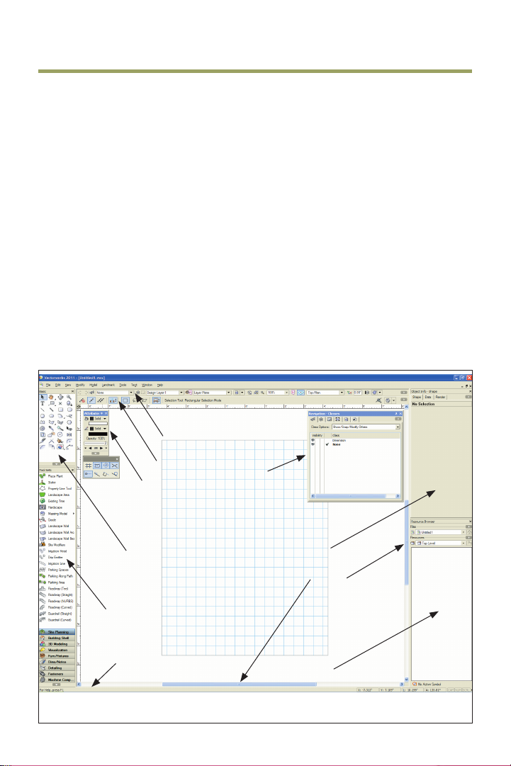
View Bar
Tool Bar
Attributes palette
Basic tools
Tool Sets
Navigation palette
2. From the menu, select Tools >
Workspaces > Landmark. If the Landmark
workspace is already active, select it again
to reset the interface. Position the
Navigation palette where shown, and
examine key areas of the interface identied
in the following gure.
Object info palette
Scroll bar
Message bar
8 | Vectorworks Landmark 2011 Getting St arted Guide
Resource Browser
Page 11

Opening the Starting File
Next, you open the supplied starting le. To
save time, this starting le contains many precongured resources, and is already fully set up
for creating a residential landscape project.
3. Close any open les, and then from the
menu, select File > Open. In the Open
Vectorworks Drawing dialog box, open the
Data Set folder and open the read-only
GS-VWLx01.vwx le. The page boundary
is displayed, and it’s ready for importing the
site plan.
4. From the menu, select File > Save As,
and save the le under the name
Landscape.vwx.
Notes:
1) Design layers are used in landscaping
projects as spatial containers for creating
drawing objects and controling object stacking
order (such as trees appearing on top of plant
beds in the Top/Plan view).
2) Sheet layers provide a 2D- only page layout
environment for printing.
3) Sheet layer viewports are individual 2D “live
camera view” objects that reside on sheet layers
but display 2D and 3D drawing objects on design
layers. When you modify drawing objects on a
design layer, the viewport itself doesn’t change,
but it displays the changes in the design layers
4) Classes are used to control display
properties of drawing objects.
5) The starting le contains additional
resources that are not required for this stream-
lined tutorial but are useful in complex landscape
design projects that use Landmark’s advanced
features. After you learn how the le structure
works, you may nd it helpful to modify the starting
le for use in your own landscaping projects.
Important: As you start the tutorial, do not be
concerned if you don’t fully understand the
le structure. As you progress through the
exercises, you will see how the le structure
works in context of a landscaping project. For
more information about the le structure from
the Landmark Getting Started website, see
www.nemetschek.net/training/2011/
landmark-2011-getting-started-guide.php.
Vectorworks Landmark 2011 Getting St arted Guide | 9
Page 12
Exercise 2: Adjusting Preference Settings
In this exercise, you verify and adjust program preferences.
Adjusting Vectorworks
Preferences
Next, you verify or adjust key application
preference settings to ensure proper
exercise operation, turn on scroll bars to
facilitate navigation, and increase the
maximum number of undos so you can
revert exercise steps if necessary.
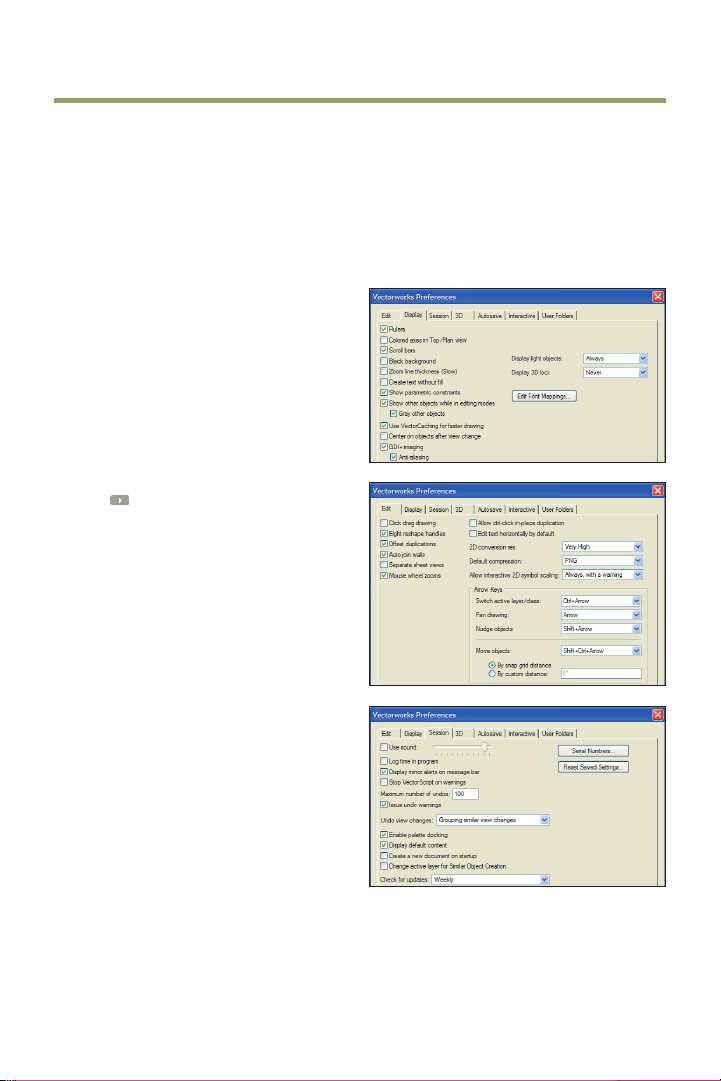
1. Click
bar and select Vectorworks Preferences.
In the Vectorworks Preferences dialog box,
select the Edit tab, and then verify or adjust
settings as shown (keep the dialog box
open for the next three steps).
2. Select the Display tab, and enable the
Scroll bars option, and then verify or adjust
other settings as shown.
3. Select the Session tab, and then enter
100 in the Maximum number of undos
eld. Verify or adjust other settings as
shown.
10 | Vectorworks Landmark 2011 Getting St arted Guide
on the far right side of the Tool
Page 13
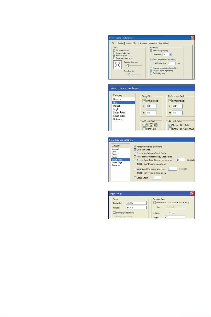
4. Select the Interactive tab, and then
change the cursor’s Selection box size and
Snap box size. Verify or adjust other
settings as shown. Click OK to save the
settings and close the dialog box.
Adjusting Grid and
Smart Point Settings
5. Press Ctrl+8 to display SmartCursor
Settings dialog box. If a tip is displayed,
click OK and then select Grid from the
Category list. Clear the Show Grid Lines
and Print Grid Lines checkboxes, and
verify or adjust other settings (.01’
[actual=3.18mm based on .125”], .04’
[actual=12.70mm based on .50”]) as shown
at left. From the Category list, click Smart
Point, and verify or adjust settings, as
shown at right. Click OK to close the dialog
box and save the changes.
Turning Off the
Page Boundary
Next, you turn off the page boundary for
clarity in the drawing area.
6. From the menu, select File > Page
Setup. In the Pages section of the Page
Setup dialog box, clear the Show page
boundary checkbox, as shown. Click OK to
save the settings, and notice that the page
boundary is no longer displayed in the
drawing area.
Vectorworks Landmark 2011 Getting St arted Guide | 11
Page 14
Setting the Default Font
Next, you adjust the default font.
7. From the menu, select Text > Font >
Arial to set the default font (if it’s not set to
Arial already), and then select Text > Size >
12 to set the default font size to 12 point
(if it’s not set to 12 already).
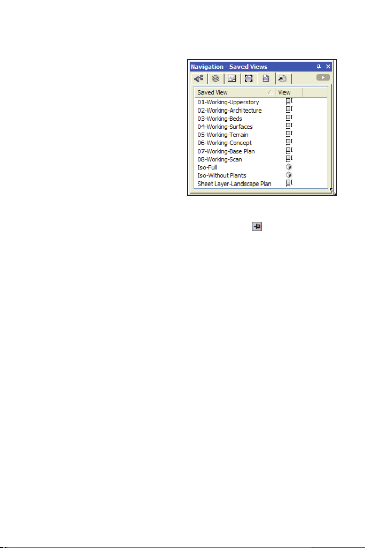
Adjusting the Navigation
Palette Display
8. If your Navigation palette is not already
displayed, from the menu, select Window >
Palettes > Navigation. If necessary,
expand the Navigation palette by dragging
the lower right corner to resize it.
9. In the Attributes and Navigation palettes,
turn on Auto Hide
you’re in a hurry to explore Landmark’s
landscaping design tools, skip Section 2
(Creating the Base Plan) and continue with
Section 3 (p. 45).
(Windows only). If
12 | Vectorworks Landmark 2011 Getting St arted Guide
Page 15

Section 2: Creating
the Base Plan
In six exercises, this section covers the following processes in the landscape design project:
• Importing the Site Plan by Dragging and Dropping (p. 14)
• Scaling the Site Plan (p. 14)
• Indexing the Site Plan with the Drawing Origin (p. 16)
• Tracing the Property Line (p. 18)
• Tracing the Easements (p. 20)
• Saving a Rotated View (p. 21)
• Drawing the House Walls (p. 22)
• Drawing the House Doors and Windows (p. 24)
• Creating the House Roof From Walls (p. 26)
• Creating the Garage Roof from a Rectangle (p. 28)
• Creating a Massing Model (p. 31)
• Drawing the Driveway (p. 33)
• Drawing the Front Porch (p. 35)
• Drawing the Sidewalks (p. 36)
• Drawing the Straight Road Segment (p. 38)
• Drawing the Curved Road Segment (p. 38)
• Drawing Existing Trees for Removal (p. 41)
• Drawing Existing Trees to Remain (p. 42)
In these exercises, you use a variety of tools on design layers to document existing site
features, which are maintained throughout the landscaping design project.
Note: If you’re in a hurry to start the design process and explore Landmark’s landscaping tools, you
can skip this section and continue with Section 3 (p. 45). If you skip Section 2 now, you should at
least review it later. You will nd it worthwhile because it covers best practices for documenting existing
site conditions, in a workow that returns the highest-level 2D and 3D benets with minimal 2D input.
Vectorworks Landmark 2011 Getting St arted Guide | 13
Page 16
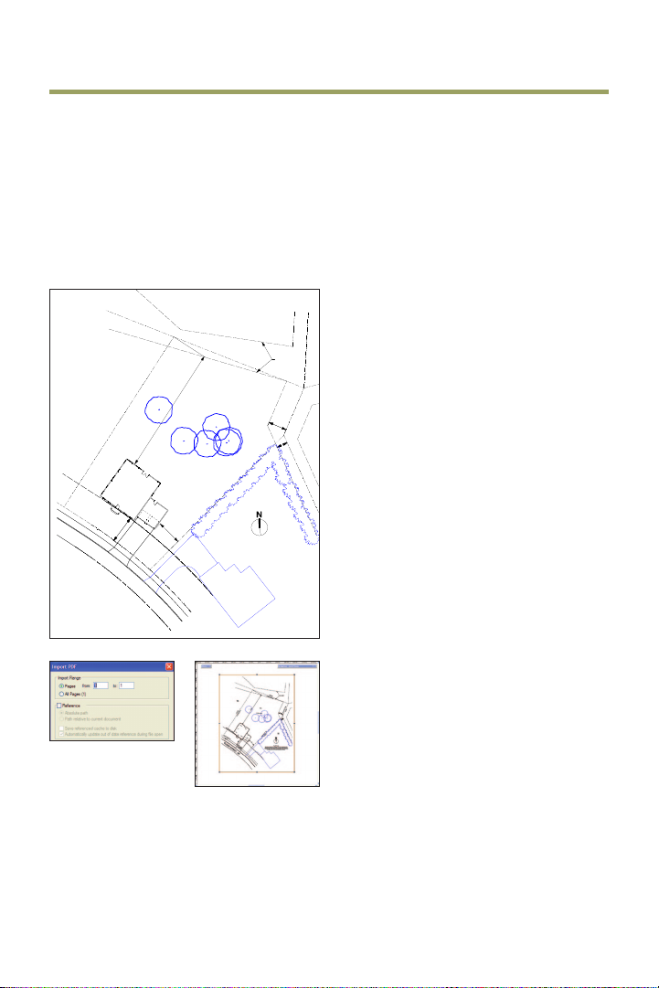
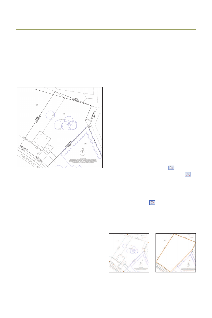
Exercise 3: Importing a Site Plan PDF File
In this exercise, you import a PDF site plan that also serves as a site inventory markup. You
then scale the imported PDF le and move it into the desired location. The completed
exercise is shown in the following gure:
Importing the Site Plan by
Dragging and Dropping
You start the exercise by opening the Data
Set folder via your operating system; you
then drag and drop the site plan le to
W
import it to your drawing.
46.97'
23°12'14"
S
1. If you did not complete Exercise 2—or
you are unsure of your le’s accuracy—
open the GS-VWLx02.vwx le.
2. Open the Data Set folder with Windows
from
Engineered
for obtaining
Explorer or Macintosh Finder. Drag and
drop the PlotPlan_InventoryMarkup.pdf
le in the approximate center of the drawing
area. In the Import PDF dialog box, click
Import to accept the defaults, as shown at
left, and import the PDF page, as shown at
right. Leave the PDF page selected for the
next ve steps.
25'
25'
N 57°09'28"
28.37'
ELDER
ELDER
BLDG LINE
BLDG LINE
W
STREET
STREET
128.00'
EASEMENT
S
68°35'18"
14
14
116.9'
E
185.22'
N 32°50'32"
Family Room
Library
Living Room
Foyer
Dining Room
25.4'
25.4'
R
R
=
=
L=69.22'
L=69.22'
425'
425'
-
50'
50'
0.54
Kitchen
Garage
23'
E
15
17'
17'
EASE
acres
44°49'10"
S
173.69'
We
information
Subdivision
EASE
10'
10'
EASE
EASE
W
16
16
PLOT
PLAN
hereby
certify
that
the
foregoing PLOT
PLAN
was prepared
provided
by
the
client
and
data
obtained
from
Plan.
This Plot
Plan
is
to
be
used by
the
a
Client
Building
Permit
and
for
other
site
related amendments.
14 | Vectorworks Landmark 2011 Getting St arted Guide
Page 17
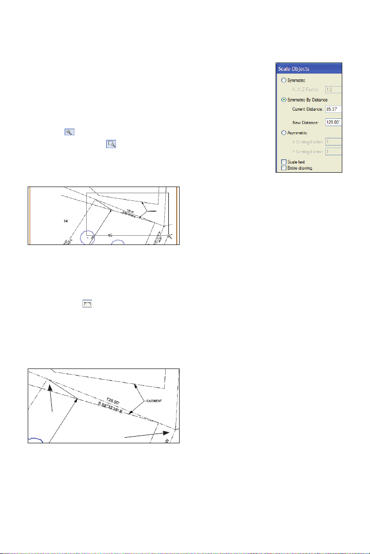
Scaling the Site Plan
Next, you scale the site plan to the full size
by snapping to property line vertices.
3. From the Basic tools palette, click the
Zoom tool
Marquee Zoom Mode
active), and then draw a marquee from upper
left to lower right, as shown, to zoom in.
4. From the menu, select Modify > Scale
Objects: Enable the Symmetric By
Distance option, and then click the Current
Distance button
in order (when your cursor is over each
vertex, press the Z key for the Snap Loupe
shortcut to temporarily zoom in—see Tip), as
shown below to specify the Current Distance.
. In the Tool bar, enable
(if it’s not already
and snap to the vertices
Enter 128’ [39.014m]
for the New Distance,
as shown at right (see
Notes), and then click
OK to scale the PDF
page. Press Ctrl+6 for
the Fit to Objects
shortcut. The zoom is
adjusted so that the
resized PDF now lls
the drawing area.
Tip: For best Snap Loupe per formance, press
Ctrl+8, select the General Category, and then
disable the Zoom Line Thickness in Snap
Loupe option.
Notes:
1) Verify that your Current Distance value is
within 0.5’ [.152m] of the value shown above. If
not, then repeat the snapping process and make
sure you position your cursor over the correct
vertex before you press the Z key to activate the
Snap Loupe.
2) Make sure the Scale text and Entire
drawing options are disabled.
vertex 1
vertex 2
Vectorworks Landmark 2011 Getting St arted Guide | 15
Page 18
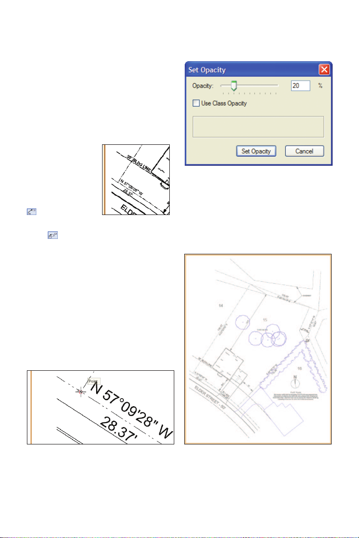
Indexing the Site Plan with
the Drawing Origin
Next, you use the Move by Points tool to
reposition the PDF page by indexing one of
the property line vertices with the drawing
origin (0,0).
5. Zoom in on the
area shown at right.
From the Basic tools
palette, click the
Move by Points tool
. In the Tool bar,
make sure Move
Mode
property vertex (SW corner shown below,
press the Z key, and make sure you snap to
the vertex). Then move your cursor and
press the Tab key ve times to highlight the X
value in the oating data bar. Enter 0 (zero)
for the value, and then press tab and enter 0
(zero) for the Y value. Press Enter twice to
move the PDF page, and then press Ctrl+6
to see the entire PDF page. The SW vertex
is now aligned with the drawing origin (0,0).
is active. Snap to the lower left
6. In the Attributes palette, click Opacity,
and set the slider to (or type in) 20% as
shown above and then click Set Opacity to
save the changes. The site plan now
appears lighter, as shown below.
16 | Vectorworks Landmark 2011 Getting St arted Guide
Page 19
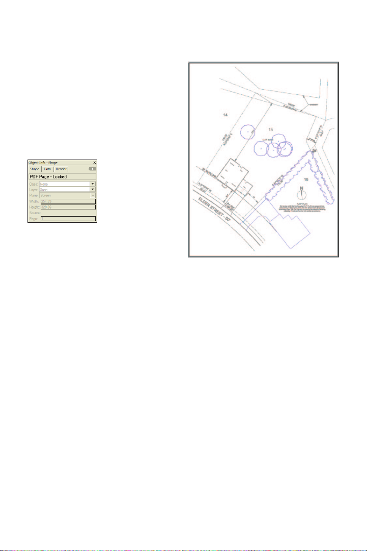
7. From the menu, select Modify > Lock.
The PDF page selection highlight turns gray
to indicate it is locked, as shown at right. In
the Object Info palette, select the Shape tab
(if it’s not already active), and notice that it
also shows that the PDF page is locked, as
shown below.
8. Save the le.
Vectorworks Landmark 2011 Getting St arted Guide | 17
Page 20
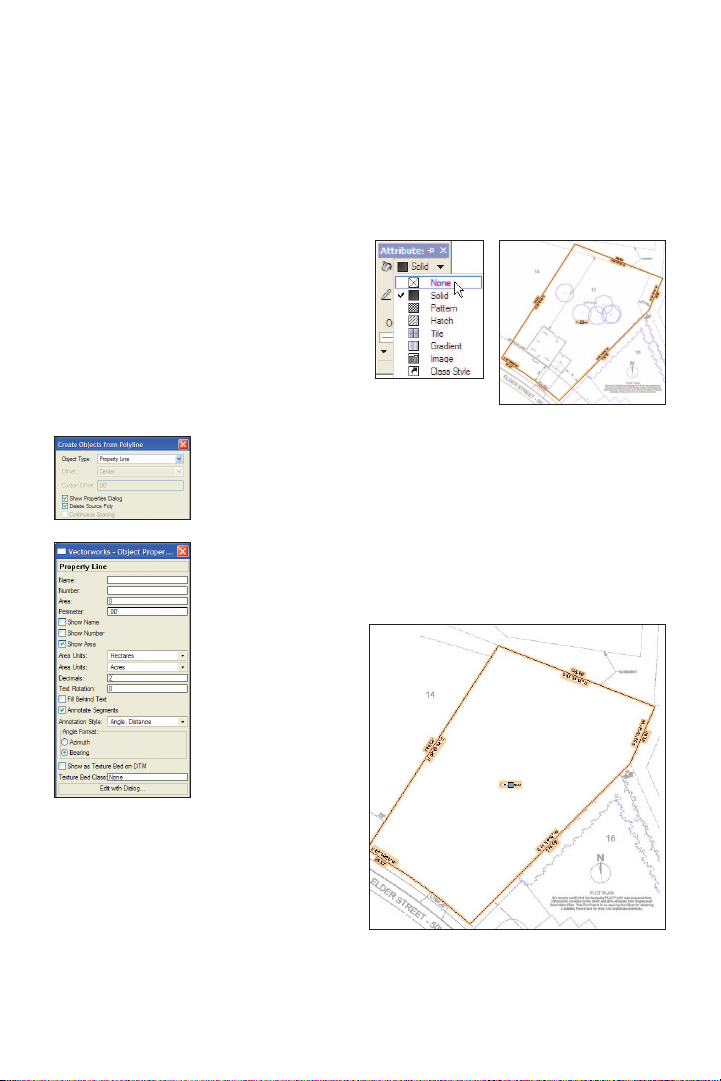
Exercise 4: Drawing the Property Line
In this exercise, you trace the property and easement lines from the imported PDF le. The
completed exercise is shown in the following gure:
1. To ensure proper operation of the
remaining exercises, close your Landscape.
vwx le (if it’s open), and then rename it.
Open the GS-VWLx03.vwx le. From the
menu, select File > Save As, and then save
the le under the name Landscape.vwx.
2. In the Navigation palette, select the
Saved Views tab, and then double-click the
07-Working-Base Plan view to activate it.
In the View bar, notice that the Base Plan
layer is now active. From the Basic tools
Tracing the Property Line
You start the exercise by opening a starting
le, and then you draw a polyline, traced
from the PDF page. You then convert the
polyline to a property line object.
Note: To try this exercise with your own le (com-
pleted Exercise 3), keep your Landscape.vwx le
open, skip step 1 and continue with step 2. If you
encounter inaccuracies in any subsequent step(s),
start over at step 1 and use the supplied le.
palette, click the Polyline tool
Tool bar, enable Corner Vertex Mode
and then snap to the vertices shown at left
(as highlighted locus points for clarity) in
order. After snapping to vertex 6, enable
Point on Arc Mode
, then snap to any
point on the arc between vertices 6 and 1,
and then snap to vertex 1 to complete the
polyline, as shown at right.
4
5
6
1
3
2
. In the
,
18 | Vectorworks Landmark 2011 Getting St arted Guide
Page 21
Note: You can snap to the PDF in this exercise
because it was created from a vector-based
source le. If you can’t snap to a PDF in your own
designs, or if you have to impor t a raster le, you
can draw individual arcs, and then draw
coincident lines by entering length and bearings
in the oating data bar’s L and A elds. You can
use the Select Connected Objects command to
select the lines and arcs, and conver t them to a
polyline or polygon with the Compose command.
You can then follow the steps below to convert it
to a property line.
4. In the Attributes palette, select None
from the Fill Style drop-down list, as shown
at left. You can now see through the
property line, as shown at right.
3. From the menu,
select Modify >
Objects from
Polyline. In the
Create Objects from
Polyline dialog box,
adjust settings as
shown at top left.
Click OK to display
the Object Properties
dialog box, and then
adjust settings, as
shown at bottom left.
Click OK to create
the property line, as
shown at right.
Next, you check property line segments and
correct them as necessary. You can choose
to optionally follow the next step, or to save
time, you can close your le and open the
GS-VWLx04-Step06.vwx le (with the
property line segments already xed) and
skip ahead to step 6 (p. 20).
Vectorworks Landmark 2011 Getting St arted Guide | 19
Page 22
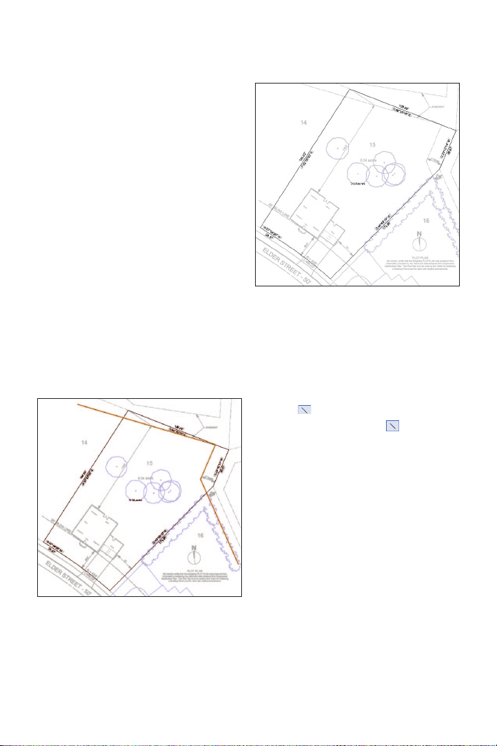
5. Zoom in and check all property line
Bearing and Distance values against the
light-gray PDF values (see Note below
gure). If any segment doesn’t match,
double-click the property line object, and
then click the Next button until the incorrect
segment’s values are activated. You can
then edit the values to match the values of
the imported site plan and click Update to
save the changes. Continue clicking Next as
necessary to correct other segments. Click
OK to save the changes, then press the X
key twice to clear the selection and examine
the completed property line, as shown.
Note: To save time and avoid repetitive cor-
rections, you can skip this step and open the GS-
VWLx04-Step06.vwx le to start the next step.
Tracing the Easements
Next, you use the Line tool to trace easement lines that lie inside the property line.
6. From the Basic tools palette, click the
Line tool
Unconstrained Line Mode is active,
and then snap to consecutive endpoints to
trace the three easement lines (highlighted
for clarity), as shown.
. In the Tool bar, make sure
20 | Vectorworks Landmark 2011 Getting St arted Guide
Note: To save time in this exercise ignore
easement lines outside of the property line and
skip the process of recreating site dimensions.
7. Save the le.
Page 23
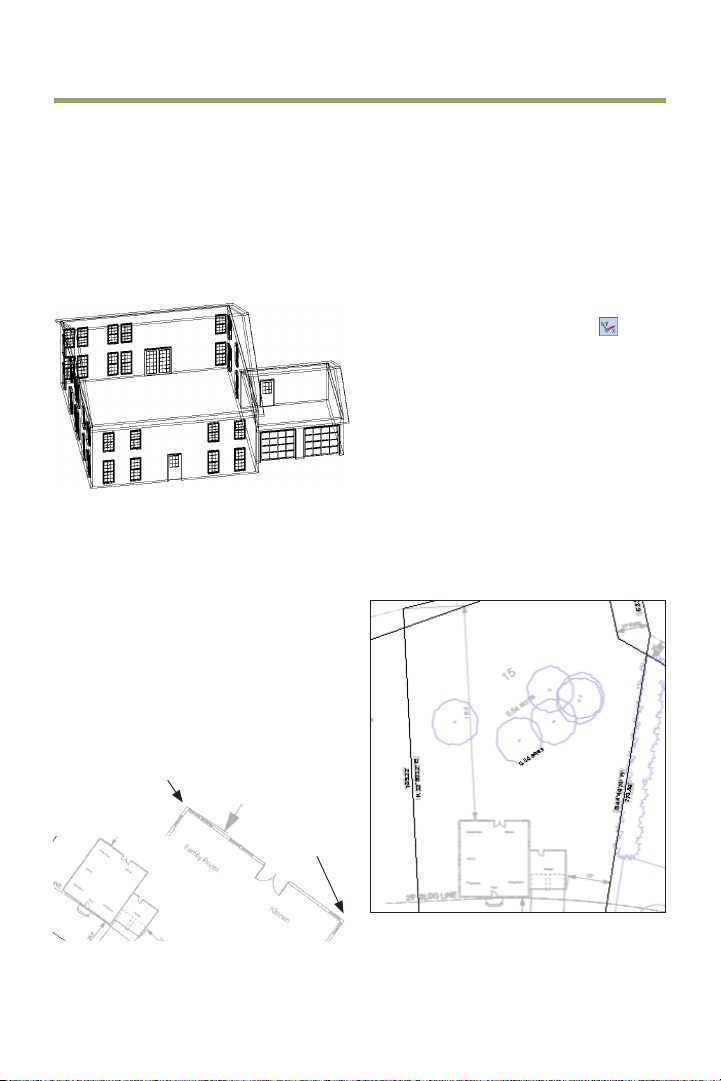
Exercise 5: Drawing the Site House
In this exercise, you save a rotated view, and then you draw a simplied version of the site
house. The completed exercise is shown in the following gure:
2. Zoom in on the house area shown at left.
Saving a Rotated View
You start the exercise by rotating the view,
and then you save the view to ensure consistency when you draw objects orthogonally in
other exercises later in the tutorial.
1. If you did not complete Exercise 4—or
you are unsure of your le’s accuracy—
open the GS-VWLx04.vwx le.
In the View bar, click Rotate Plan
to exterior endpoints (pause briey over
each vertex to display the Endpoint
SmartCursor cue) in the order shown at
center to rotate the plan view. Notice the
indicator in the drawing area, and in the
View bar conrm that the Current Plan
Rotation angle is 35.80º (if not, press Ctrl+Z
to undo the view rotation and try again).
Press Ctrl+6, and then zoom in on the area
shown at right.
. Snap
endpoint 1
endpoint 2
Vectorworks Landmark 2011 Getting St arted Guide | 21
Page 24
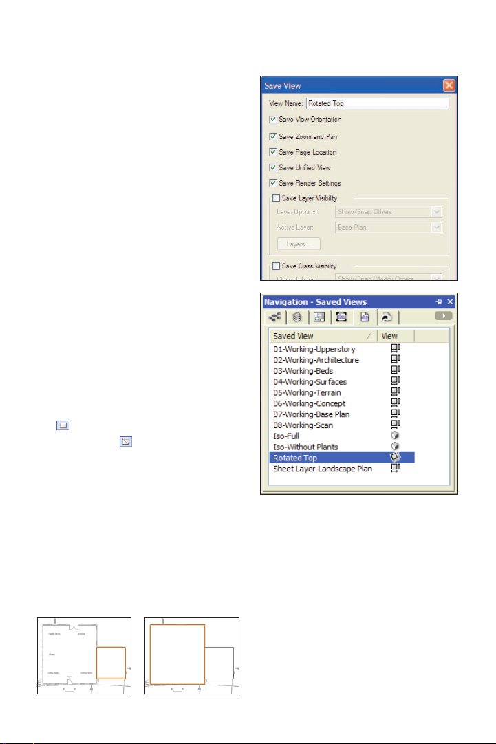
3. In the Navigation palette, select the Saved
Views tab, and then right-click the blank area
to the right of the list and select New. In the
Save View dialog box, adjust the settings as
shown at top right (make sure the Save
Layer Visibility and Save Class Visibility
options are disabled), and then click OK to
save the view. If necessary, resize the
Navigation palette so all saved views are
visible, and notice the new saved view’s
rotated view icon, shown at bottom right.
Drawing the House Walls
Next, you draw rectangles from the house
outline for tracing purposes, and then you
use pre-congured wall styles in your le to
draw the existing house walls.
4. Zoom in on the house and garage. From
the Basic tools palette, click the Rectangle
tool
. In the Tool bar, make sure
Rectangle Mode
snapping to the top right outside corner of
the garage wall, and then complete the
rectangle by snapping to the point where the
front garage wall meets the house wall, as
shown at top. With the Rectangle tool still
active, snap to top right outside corner of
the house, and then snap to the bottom left
outside corner to complete the second
rectangle, as shown at bottom.
is active. Start by
Notes:
1) You draw rectangles to ensure the house
walls and roofs will be square. In your own
designs, make sure the rectangle edges are
collinear (it’s not necessary for this tutorial
because you can use a supplied le with this
xed, later in Exercise 14).
2) If you don’t have a oor plan to import in
your own designs, refer to the Getting Started with
Vectorworks Architect (current version) tutorial for
an efcient workow for drawing oor plans.
22 | Vectorworks Landmark 2011 Getting St arted Guide
Page 25

5. Press the X key twice to clear the current
selection. In the Navigation palette, select
the Design Layers tab, and then turn off
visibility of the Scan layer, as shown (only
the rectangles are now visible). In the
Resource Browser, scroll down and open
the Wall Styles folder (if it’s not open
already). Double-click the Ext-Siding-
Framing wall style. Open the Building Shell
tool set, and notice that the Wall tool
is
now active. In the Tool bar, make sure Left
Control Line Mode
is active.
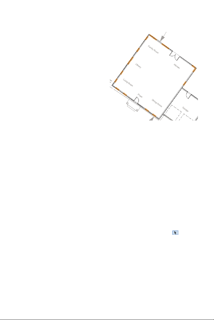
6. Snap to the four corners of the house
rectangle in clockwise order (starting on any
corner), and then snap to the start point to
create four walls, as shown left. With all four
walls selected, in the Object Info palette
change the ±Z value to 17.00’ [5.182m], as
shown at right, and then press Enter.
7. With the Wall tool
still active, snap to
the four corners of the garage rectangle in
clockwise order. Start at the top left corner
(when the house wall highlights), and when
the house wall highlights at the bottom left
corner, click to create three walls, as shown
(do not change the ±Z value for the shorter
garage walls).
Vectorworks Landmark 2011 Getting St arted Guide | 23
Page 26

Drawing the House Doors
and Windows
Next, you temporarily adjust the display so
you can see the PDF page through the
walls, and then you create doors and
windows with the Door and Window tools
and by inserting pre-congured symbols.
8. Press the X key
twice to clear the
selection. In the
Navigation palette:
• Turn on visibility
of the Scan layer, as
shown. Notice that
the rectangle and walls block objects in the
PDF page.
• Right-click the Base Plan layer, and
select Edit from the context menu. In the Edit
Design Layers dialog box, change the
Opacity to 20%, as shown at right, and then
click OK. Notice that you can now see
objects in the PDF page.
• Select the Saved views tab, and then
double-click the 07-Working-Base Plan
saved view to activate it. Notice that the layer
opacity doesn’t revert to 100% because the
pre-congured saved view is set to only
control the visibility state of layers.
9. Zoom in on the
house and garage.
From the Building
Shell tool set, click
the Door tool
.
Click the center of
the foyer door (click once) in the PDF page.
Move your cursor, and notice how your
cursor position ips the door side and swing.
Click when the preview matches the
orientation in the PDF page to place the door
plug-in object as shown. In the Object Info
palette, verify a “Door In Wall” is selected. If
not, drag the door to reinsert it in the wall.
Tip: You can nudge a selected door, symbol, or
window to incrementally adjust its position. To do
this, hold down the Shift key and press any of the
four arrow keys as necessary.
24 | Vectorworks Landmark 2011 Getting St arted Guide
Note: The Door tool was pre-congured for this
le. The Door Settings dialog box would normally
be displayed for the rst door object inserted in a
le. For subsequent insertions in your own les,
click Preferences from the Tool bar before
placing the door to set default door parameters. If
you change Door Settings dialog box settings, all
subsequent insertions are affected.
Page 27
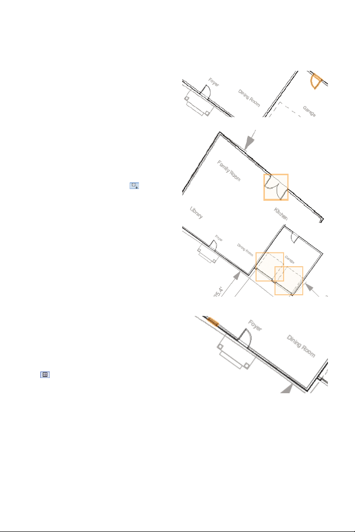
10. With the Door tool still active, insert
another door in the rear garage wall,
matching the orientation in the PDF page,
as shown.
11. In the Resource Browser, scroll down
and open the Symbols/Plug-In Objects
folder (if it’s not open already). Scroll down
the list and double-click the Door-Patio
symbol. In the Basic tools palette, notice
that the Symbol Insertion tool
is now
active. Click once in the center of the rear
door of the PDF page, and then click
outside the wall to orient and insert the
symbol, as shown.
12. In the Object Info palette, verify a
“Symbol In Wall” is selected. If not, drag the
symbol to reinsert it in the wall. In the
Resource Browser, scroll down the symbol
list and double-click the Door-Garage-OHD
symbol. Insert two garage doors to match
the position and orientation of the PDF
page, where shown (highlighted for clarity)
in the front garage wall.
13. Zoom in on the house’s front wall. From
the Building Shell tool set, click the Window
tool
. Click the center of the window on
the left side of the front door, and then click
outside the wall to orient and place the
window plug-in object, as shown. In the
Object Info palette, verify a “Window In
Wall” is selected. If not, drag the window to
reinsert it in the wall.
Vectorworks Landmark 2011 Getting St arted Guide | 25
Page 28
Note: The Window tool was pre-congured for
this le. The Window Settings dialog box would
normally be displayed for the rst window object
inserted in a le. For subsequent inser tions in
your own les, click Preferences from the Tool
bar before placing the window to set default
window parameters. If you change the Window
Settings dialog box settings, all subsequent
insertions will be affected.
14. With the Window tool still active, insert
the remaining 16 windows by clicking the
center to position them and then clicking
outside the wall to orient them, as shown (all
17 windows are highlighted for clarity).
15. In the Navigation palette, select the
Design Layers tab, and then:
• Turn off visibility of the Scan layer.
• Right-click the Base Plan layer, and
select Edit from the context menu. In the
Edit Design Layers dialog box, change the
Opacity to 100%, and then click OK to save
the change.
16. In the Resource Browser, scroll down
the symbol list and double-click the
Window-Floor2 symbol. Click the insertion
point of each existing window, and then click
outside to orient the symbol (see Note
below). Start with the rst window you
created, and continue in a clockwise
direction to insert a total of 17 window
symbols (in the same positions highlighted
in the previous gure).
Note: After inser ting each window symbol, verify
that a “Symbol In Wall” is selected in the Object
Info palette. If not, drag the symbol to reinsert it
in the wall.
Creating the House Roof
from Walls
Next, you create a roof object from the
house walls.
17. If necessary, adjust the display so you
can see the entire house and garage. Press
the X key twice to clear the current selection
and activate the Selection tool
down the Shift key and click the four house
walls (away from the windows; avoid
selecting the garage walls) to add them to
the current selection set. In the Object Info
palette, verify that four walls are selected.
. Hold
26 | Vectorworks Landmark 2011 Getting St arted Guide
Page 29
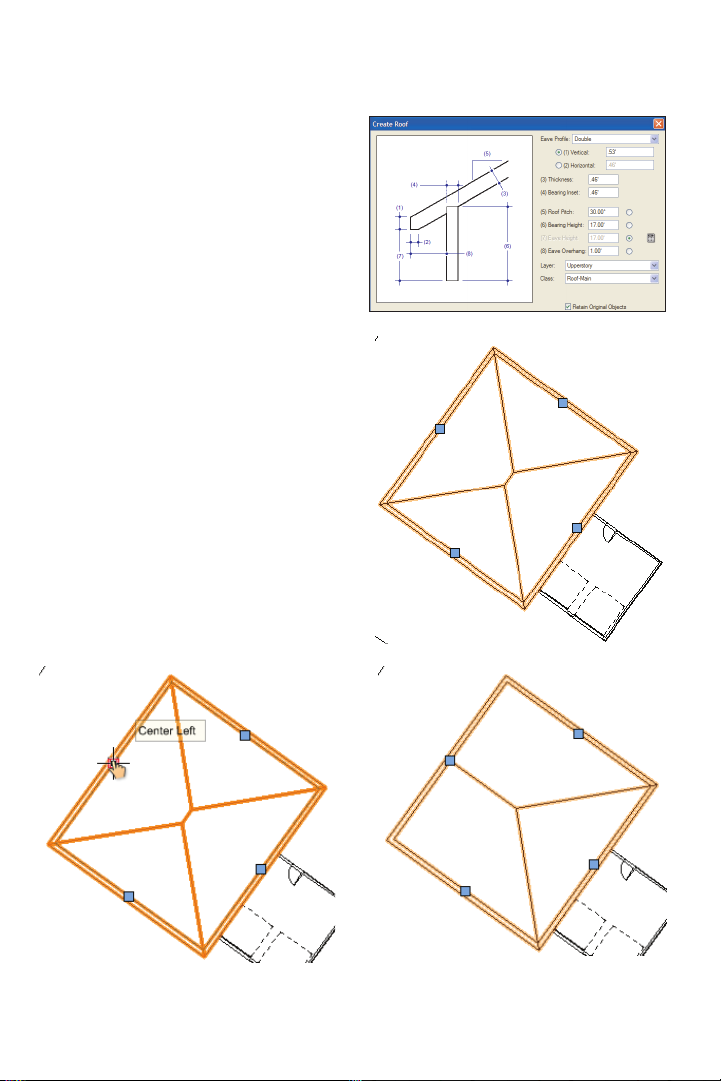
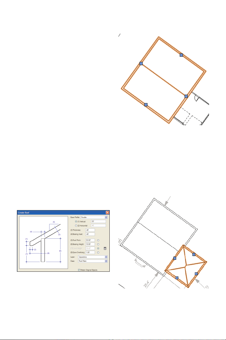
18. With the four walls still selected, select
Landmark > AEC > Create Roof from the
menu. In the Create Roof dialog box,
change settings (.53’ [.162m], .46’ [.140m],
17.00’ [5.182m], 1.00’ [.305m]) as shown at
top. Click OK to create the roof, and then
press Ctrl+5 and Ctrl+6 to adjust the
display. In the View bar, notice that the
Upperstory layer is now active (so you can
see the roof). Also notice that Vectorworks
created a hip roof by default, as shown at
bottom.
Next, you modify the roof to create the
desired gabled ends.
19. Select the roof’s center left control
point, as shown at left. In the Edit Roof
Settings dialog box, select the Gable option,
and then click OK to create the gabled end,
as shown at right.
Vectorworks Landmark 2011 Getting St arted Guide | 27
Page 30
20. Repeat the process to change the
center right side to a gabled end, as shown.
Creating the Garage Roof
from a Rectangle
Next, you use the garage rectangle (that you
drew earlier) to create the smaller roof over
the garage.
21. In the Navigation palette, activate the
07-Working-Base Plan saved view. Notice
that the roof is no longer visible because the
Upperstory layer visibility is turned off in the
07-Working-Base Plan saved view.
22. Zoom in on the garage, and then press
the X key and click in the middle of the
garage to select the rectangle. From the
menu, select Landmark > AEC > Create
Roof. In the Create Roof dialog box, change
settings (.53’ [.162m], .46’ [.140m], 10.00’
[3.048m], 1.00’ [.305m]) as shown at left,
and then click OK to create the roof.
Press Ctrl+5 and Ctrl+6 to adjust the display,
and examine the roof, shown at right.
Notice that the garage roof now appears on
top of the house roof— even though it’s
lower in elevation—because of the object
stacking order (in this case, the display order
is based on the order of object creation).
28 | Vectorworks Landmark 2011 Getting St arted Guide
Page 31

Next, you, modify the garage roof to remove
the eave overhang on the house side, and
then you create the desired gabled ends.
You then complete the roofs by changing
the stacking order of the house roof.
23. Select the garage roof’s center left
control point. In the Edit Roof Settings
dialog box, select the Gable option, and
then change the Eave Overhang to 0 (zero),
as shown at top. Click OK to create the
gable end and remove the overhang, as
shown below.
24. Repeat the process to change the
garage roof’s center right side to a gabled
end (but do not change the Overhang
value), as shown above. Right-click the
house roof and select Send > Send to
Front from the context menu. Press the X
key twice to clear the current selection, and
notice that the house roof is now on top of
the garage roof, as shown below.
Vectorworks Landmark 2011 Getting St arted Guide | 29
Page 32

25. From the View bar, select the Left
Isometric view from the Standard View
drop-down list. Press Ctrl+6 to adjust the
display, and then zoom in on the house and
examine the 3D geometry of all the objects
you created, as shown.
26. Save the le.
30 | Vectorworks Landmark 2011 Getting St arted Guide
Page 33

Exercise 6: Drawing the Adjacent House
In this short exercise, you create a massing model to represent the house next door. The
completed exercise is shown in the following gure:
2. In the Navigation palette, activate the
07-Working-Base Plan saved view. In the
Basic tools palette, click the Pan tool
and then pan the view by “dragging” the
neighbor’s house to the approximate center
of the screen. Zoom in on the area shown.
Creating a Massing Model
You start the exercise by resetting the view,
and then you activate the Massing Model
tool and trace the outline of the neighbor’s
house on the PDF page.
1. If you did not complete Exercise 5—or
you are unsure of your le’s accuracy—
open the GS-VWLx05.vwx le.
3. From the Site Planning tool set, click the
Massing Model tool
make sure Corner Vertex Mode
active. Starting at the bottom vertex, snap to
vertices in a clockwise order. Double-click
the far right (next to last) vertex to
automatically close the prole, and create
the massing model, as shown. Leave the
massing model selected for the next step.
. In the Tool bar,
is
,
Vectorworks Landmark 2011 Getting St arted Guide | 31
Page 34

Note: The Massing Model tool was pre-cong-
ured for this le. The Object Proper ties dialog
box would normally be displayed for the rst
massing model object inserted in a le. For
subsequent insertions in your own les, click
Preferences from the Tool bar before creating a
massing model to set default parameters. If you
change settings in the Object Properties dialog
box, all subsequent insertions are affected.
4. In the Object Info palette, change the
massing model’s Class to Existing-remain,
(enable the option and click Yes in the
dialog box shown at left). From the View
bar, select the
Left Isometric view from
the Standard View drop-down list. Press
Ctrl+6 to adjust the display, and then press
the X key twice to clear the selection.
Examine the completed massing model,
shown at right.
5. Save the le.
32 | Vectorworks Landmark 2011 Getting St arted Guide
Page 35

Exercise 7: Drawing the Paved Areas
In this exercise, you use various tools to draw the existing driveway, front porch, sidewalk,
and streets. The completed exercise is shown in the following gure:
Drawing the Driveway
You start the exercise by adjusting layer and
class visibilities, and then you use the Hard-
scape tool to draw the driveway and apron.
1. If you did not complete Exercise 6—or
you are unsure of your le’s accuracy—
open the GS-VWLx06.vwx le.
2. In the Navigation palette:
• Activate the 04-Working-Surfaces
saved view.
• Select the Design Layers tab, and turn
on visibility of the Scan layer (shown at left)
so you can see the PDF page.
• Select the Classes tab, and turn off visibil-
ity of the Building class, and activate the
Existing-remain class, as shown at right.
Vectorworks Landmark 2011 Getting St arted Guide | 33
Page 36

3. Zoom in on the
area shown at left.
From the Site
Planning tool set,
click the Hardscape
tool
. In the Tool
bar, make sure that
Corner Vertex Mode
click Preferences
is active, and then
. If they’re not already
selected, select By Class from both the Main
Texture and Border Texture drop-down lists.
Click the boundary vertices (shown at center
as highlighted locus points for clarity) in
clockwise order starting at the lowest vertex,
and then click the start point again to create
the hardscape object, shown at right. Leave
the hardscape selected for the next step.
Note: The Hardscape tool was pre-congured
for this le. The Hardscape Object Settings
dialog box would normally be displayed for the
rst door object inserted in a le. For subsequent
insertions in your own les, click Preferences
from the Tool bar before creating a hardscape to
set default parameters. If you change settings in
the Hardscape Object Settings dialog box, all
subsequent insertions will be affected.
Next, you reshape the hardscape object so
that it’s ush with the front garage wall.
4. Zoom in on the area shown at left. Press
the X key, and then double-click the
hardscape object to activate the 2D
Reshape tool
. In the Tool bar, make sure
Move Polygon Handles Mode is active.
Click the top left grip to “pick up” the vertex.
Move your cursor over the left driveway line,
and press the T key to set the surface snap.
Move your cursor over the front edge of the
garage rectangle, and press the T key to set
another surface snap. Move your cursor to
the intersection of both surfaces, and press
the Z key (press it again if necessary), and
then click when the Surface/Surface
SmartCursor cue is displayed (shown at
center). The driveway hardscape maintains
its width and is now ush with the garage
front edge, as shown at right.
left driveway
line
garage
rectangle
front edge
left driveway line
garage
rectangle
front edge
34 | Vectorworks Landmark 2011 Getting St arted Guide
Page 37

5. Press Ctrl+6, and then press the X key
twice to clear the selection. Examine the
completed driveway hardscape, shown
at right.
Drawing the Front Porch
Next, you draw another boundary hardscape for the front porch.
6. Zoom in on the area shown at top. From
the Site Planning tool set, click the
Hardscape tool
boundary vertices (press the Z key as
necessary) to create the hardscape, as
shown at bottom, and then press the X key
twice to clear the selection.
. Snap to the porch’s
Note: To save time, ignore the front porch step in
the PDF page.
Vectorworks Landmark 2011 Getting St arted Guide | 35
Page 38

Drawing the Sidewalks
Next, you create the sidewalk by drawing
individual polyline and line objects, which
you then compose into a polyline that you
convert to a hardscape object.
7. In the Navigation palette:
• Select the Saved Views tab, and then
activate the 07-Working-Base Plan saved
view. Then zoom in on the area shown.
• Select the Design Layers tab, and then
turn off visibility of the Scan layer.
8. From the Basic tools palette, click the
Polyline tool
Corner Vertex Mode , and then snap
to vertices 1 and 2 (shown at left as
highlighted locus points for clarity) in order.
1
. In the tool bar, enable
2
3
4
After you snap to vertex 2 (arc start), enable
Point on Arc Mode
in the Tool bar, and
snap to vertex 3 (arc midpoint). Then
double-click vertex 4 to complete the
polyline shown at right. Leave the polyline
selected for the next step.
9. In the Navigation palette, turn on visibility
of the Scan layer. From the Basic tools
palette, click the Offset tool
bar, enable Offset by Point Mode
Duplicate and Offset Mode
. In the Tool
and
. Click the
endpoint shown at left, and then wait for the
duplicate preview display. Click it again to
create an offset duplicate of the polyline, as
shown at right.
36 | Vectorworks Landmark 2011 Getting St arted Guide
Page 39

10. From the Basic tools palette, click the
Line tool
. Snap to the endpoints of both
polylines to create two lines, as shown at
left (highlighted for clarity). Select one of the
lines, and then select Edit > Select
Connected Objects from the menu to
automatically select the arcs and lines
(conrm that four objects are selected in the
Object Info palette). From the menu, select
Modify > Compose. The lines and arcs are
combined into a single polyline object, as
shown at right. Leave the polyline selected
for the next step.
11. From the menu, select Modify > Objects
from Polyline. In the Create Objects from
Polyline dialog box, adjust settings as shown,
and then click OK to create the hardscape
object. In the Object Info palette, change the
following hardscape details:
• Class to Existing-remain.
• Layer to Surfaces (the hardscape
disappears, and the Object Info palette
shows “No Selection” because the Surface
layer is currently invisible).
Next, you use the Clip Surface command
with the hardscape objects to subtract the
area of the sidewalk from the driveway.
12. In the Navigation palette, activate the
04-Working-Surfaces saved view. Press
the X key, and then hold down the Shift key
and select the driveway to add it to the
selection (in the Object Info palette, verify
that two hardscape objects are selected).
Right-click the selection, and then select
Clip Surface from the context menu. Select
only the driveway apron and notice that the
area of the sidewalk was removed from it,
as shown.
Vectorworks Landmark 2011 Getting St arted Guide | 37
Page 40

Drawing the Straight
Road Segment
Next, you use the Roadway (Straight) tool
to draw the straight portion of the road. You
draw the roadway object on the sidewalk
edge to facilitate snapping (in this site, the
sidewalk and road centerlines are parallel),
and then you move it into place later.
13. Zoom in on left half of the sidewalk, as
shown above at left. From the Site Planning
tool set, click the Roadway (Straight) tool
, and then snap to the point where the
sidewalk’s straight segment meets the arc, as
shown above at center. Click the sidewalk’s
left endpoint (shown above at right) to
complete the straight roadway segment.
Note: The Roadway (Straight) tool was
pre-congured for this le. The Roadway
(Straight) dialog box would normally be displayed
for the rst straight roadway object inserted in a
le. For subsequent insertions in your own les,
click Preferences from the Tool bar before
creating a straight roadway to set default
parameters. If you change settings in the
Roadway (Straight) dialog box, all subsequent
insertions will be affected.
Drawing the Curved
Road Segment
Next, you use the Roadway (Curved) tool
to draw the arc portion of the road, and then
you move and rotate it into position.
14. From the Site Planning tool set, click
the Roadway (Curved) tool
click the top right corner of the straight
roadway segment. After a few seconds, the
curved roadway object is created. Press
Ctrl+6 so you can see it, and then press the
X key and drag the curved segment close to
the straight segment as shown above. Zoom
in on the area between the two roadway
objects, as shown at the top of page 41.
. Double-
38 | Vectorworks Landmark 2011 Getting St arted Guide
Page 41

Note: The Roadway (Curved) tool was
pre-congured for this le. The Roadway
(Curved) dialog box would normally be displayed
for the rst curved roadway object inserted in a
le. For subsequent insertions in your own les,
click Preferences from the Tool bar before
creating a curved roadway to set default
parameters. If you change settings in the
Roadway (Curved) dialog box, all subsequent
insertions will be affected.
15. Press the X key, and then drag the
curved roadway object by its top left corner
and snap it to the straight roadway object’s
top right corner (if necessary, press the Z
key to temporarily zoom in), as shown below
at left. From the Basic tools palette, click the
Rotate tool
. For the center of rotation,
snap to the endpoint where it meets the
straight roadway object, as shown at left.
Snap to the other endpoint of the curved
roadway object (shown below at center) to
set the reference angle. Snap to the other
endpoint of the straight roadway object
(shown at right) to specify the new angle
and complete the rotation. Leave the curved
roadway object selected for the next step.
Tip: You can snap to any points on the roadway
edges to specify the reference and new angles;
you don’t have to align points on the same radius.
Vectorworks Landmark 2011 Getting St arted Guide | 39
Page 42

Next, you turn on visibility of the PDF page,
and then you use the Move by Points tool
to move both roadway objects into position.
16. In the Navigation palette, select the
Design Layers tab, and then turn on visibility
of the Scan layer. Press the X key, and then
hold down the Shift key and select the
straight roadway object (two objects should
now be selected). From the Basic tools
palette, select the Move by Points tool
For the start point, snap to the insertion
point of the straight roadway, as shown at
top. For the end point, snap to the arc
endpoint of the road centerline (shown at
bottom) to move the roadway objects into
place. Leave both roadway objects selected
for the next step.
.
17. In the Object Info palette, change the
class of both roadway objects to Existing-
remain. Press the X key, and then hold down
the Shift key and select the porch, sidewalk,
and both driveway hardscapes to add them
to the current selection (six objects should be
selected). In the Attributes palette, click the
Solid Fill Color button, and select the gray
color shown at left. Press the X key twice,
and then activate the 04-Working-Surfaces
saved view. Examine the completed paved
areas, as shown.
18. Save the le.
40 | Vectorworks Landmark 2011 Getting St arted Guide
Page 43

Exercise 8: Drawing Existing Vegetation
In this exercise, you draw trees to be demolished to make room for new landscaping
features, and you draw trees in the adjacent lot. The completed exercise is shown in the
following gure:
2. From the Site Planning tool set, click the
Drawing Existing Trees
for Removal
You start the exercise by drawing existing
trees in the back yard that will be demolished.
1. If you did not complete Exercise 7—or
you are unsure of your le’s accuracy—
open the GS -V WL x07.v w x le.
Existing Tree tool
tree, double-click the center of the tree
“sketched” on the PDF page, where shown
below at left. After a few seconds, the tree is
created, as shown at right.
Note: The Existing Tree tool was pre-congured
for this le. The Object Properties dialog box
would normally be displayed for the rst existing
tree object inserted in a le. For subsequent
insertions in your own les, click Preferences
from the Tool bar before placing the tree to set
default existing tree parameters. If you change
the Object Properties dialog box settings, all
subsequent insertions are affected.
. To place the rst
Vectorworks Landmark 2011 Getting St arted Guide | 41
Page 44

3. With the Existing Tree tool still active,
continue double-clicking the centers of the
“sketched” trees to create all six trees. From the
Basic tools palette, click the Select Similar tool
. Click one of the trees to automatically
select all six. In the Object Info palette, conrm
all six existing trees are selected, and then
change the Class to Demolition, and change
the Plane to Screen. Press the X key twice to
clear the selection and examine the trees, as
shown at top.
Drawing Existing Trees
to Remain
Next, you use the Place Plant tool to draw a
line of existing trees in the neighbor’s yard.
4. From the Site
Planning tool set,
click the Place Plant
tool
. In the Tool
bar, enable Poly-
Edge Spaced Mode
, and then click Preferences . In the
Place Plant Preferences dialog box, select
Exis Evergreen from the Symbol list, adjust
the Spacing (shown at left: 10.00’ [3.048m]),
and then click OK. Click the three points
(shown at center as highlighted 2D locus
points for clarity) from left to right approximately where shown. Double-click the lower
right point to terminate the line. After several
seconds, the plant object is created, as
shown at bottom. Leave the plant object
selected for the next step.
42 | Vectorworks Landmark 2011 Getting St arted Guide
Page 45

Notes:
1) Some symbols in the list are default
content, available for all les. The other symbols
were included in the star ting le to save time.
2) The Place Plant Preferences dialog box is
only displayed for the rst plant object inserted in
a le. For subsequent insertions, click Prefer-
ences from the Tool bar before placing the plant
to set default plant parameters. If you change
settings in the Place Plant Preferences dialog
box, all subsequent insertions will be affected.
5. In the Object Info
palette, verify or adjust
settings (10.00’
[3.048m]), as shown at
right, and then press
the X key twice to clear
the selection. Examine
the completed existing
trees, shown below.
6. Save the le.
Vectorworks Landmark 2011 Getting St arted Guide | 43
Page 46

Page 47

Section 3: Laying Out
Constructed Elements
In four exercises, this section covers the following processes in the landscape design project:
• Creating a Privacy Fence from Walls (p. 48)
• Laying Out the Pool Area with Construction Geometry (p. 52)
• Inserting the Pool Symbol (p. 56)
• Drawing the Pool Deck (p. 56)
• Drawing the Pool House Walls (p. 57)
• Drawing the Pool House Roof (p. 59)
• Drawing the Seat Wall (p. 60)
• Drawing the Seat Wall Cap (p. 61)
• Mirroring Objects (p. 61)
• Inserting the Pergola Symbol (p. 63)
• Inserting the Gazebo Symbol (p. 64)
• Inserting the Bench Symbol (p. 65)
In these exercises, you start developing landscaping features by creating the following
construction elements to delineate key landscaping and activity areas that drive the design:
• Creating a privacy fence
• Inserting the pool symbol and draw the decking and pool house
• Drawing the seat walls
• Inserting pre-congured symbols for the pergola, gazebo, and seating features.
Vectorworks Landmark 2011 Getting St arted Guide | 45
Page 48

Exercise 9: Drawing the
Privacy Fence
In this exercise, you use existing geometry to create a privacy fence made of wall objects.
The completed exercise is shown in the following gure:
Creating a Privacy Fence
from Walls
You start the exercise by copying fence
boundary geometry from the Base Plan
layer, and then you paste it in place on the
Beds layer.
1. If you did not complete Exercise 8—or
you are unsure of your le’s accuracy—
open the GS-VWLx08.vwx le.
2. Press the X key, and then hold down the
Shift key and select the property line and
the two easement lines, shown at top right.
Press Ctrl+C to copy the objects. In the
Navigation palette, activate the
03-Working-Beds saved view, and then
press Ctrl+Alt+V to paste the easement
lines in place, as shown at bottom right.
46 | Vectorworks Landmark 2011 Getting St arted Guide
Page 49

Next, you draw a line for the fence boundary
at the house.
3. Press the X key twice to clear the current
selection. From the Basic tools palette, click
the Line tool
. Move your cursor over the
house wall where shown below at left, and
then press the Z key to zoom in. Move the
cursor over the house wall’s inside edge
(shown below at center) and press the T
key to set a surface snap. Draw a line by
snapping to the surface line (outside the
property line), as shown below at right. In
the Navigation palette, select the Design
Layers tab, and then turn off visibility of the
Base Plan and Surfaces layers.
Next, you offset the easement lines, and
then you create a llet to connect them
and Offset Original Object Mode
, and
then change the Distance value to 1.00’
[.305m] and press Enter. Click inside the line
(near the middle of the boundary lines) to
offset the line 1’ [.305m], as shown at left.
Keep holding down the Space bar for the
Boomerang mode shortcut, press the X key
once, and then select the short easement
line. Release the Space bar, and then click
ve times to the left of the line to offset it a
total of 5’ [1.524m] from the original, as
shown at right.
4. Press the X key and select the long
easement line. From the Basic tools palette,
click the Offset tool
. In the Tool bar,
enable both Offset by Distance Mode
Note: Boomerang mode lets you adjust the
display and perform other operations without
exiting the active tool.
Vectorworks Landmark 2011 Getting St arted Guide | 47
Page 50

5. From the Basic tools palette, click the
Fillet tool
and Trim Mode
active), and then click Preferences
. In the Tool bar, enable Fillet
(if it’s not already
. In
the Fillet Settings dialog box, change the
Fillet Radius to 90.00’ [27.432m], and then
click OK. Click both easement lines to
create the llet and trim (and extend) both
lines, as shown.
Next, you create a polygon from the
boundary objects, and then you convert it to
wall objects.
6. From the Basic tools palette, click the 2D
Polygon tool
Inner Boundary Mode
. Activate Polygon From
in the Tool bar.
Click anywhere inside the boundary lines to
create the polygon (fence perimeter), as
shown.
7. Press the X key to exit the 2D Polygon
tool, and then press Ctrl+A to select all six
objects. Hold down the Shift key, and select
the center of the polygon to deselect it (ve
objects should now be selected). Press the
Delete key to remove them from the drawing.
8. In the Resource Browser, scroll down
and expand the Wall Styles section, and
then double-click the Wood Privacy Fence
wall style to activate it. Press the X key, and
then select the polyline. From the menu,
select Modify > Objects from Polyline. In
the Create Objects from Polyline dialog
box, adjust settings as shown at left
48 | Vectorworks Landmark 2011 Getting St arted Guide
Page 51

(changing the Offset to Right creates walls
inside the polyline), and then click OK to
create the walls. Press the X key twice to
clear the selection, and examine the walls,
shown at right.
Next, you use the Wall Join tool
to
connect the round wall segment with the
adjacent straight segments.
9. From the Building Shell tool set, click the
Wall Join tool
Join Mode
. In the Tool bar, enable L
(if it’s not already active).
Click wall segments in order, approximately
where shown. The walls are joined, but their
appearance does not change (see Notes
below gure).
Notes:
1) Although these walls appear to be joined
after the polygon conversion, you still need to join
them so you can create polygons inside their
boundaries later in Exercise 14.
2) All corners where straight wall segments
meet were already joined by the polygon
conversion operation.
Next, you drag the wall objects to offset
them.
Note: The next step works as described if you
have Vectorworks Designer. If you don’t have
Vectorworks Designer or Vectorworks Architect,
the Enable Connected Walls Mode option is
not available. Start the step as instructed, and
then after you press the X key, immediately star t
1
2
3
4
dragging the wall segment that touches the
house toward the street. Press the Tab key once,
and then enter 18’ [5.486m] for the offset value
and press Tab. Continue dragging the wall
segment and release the mouse button when the
Perpendicular/Length SmartCursor cue is
displayed (the wall connection is not main-
tained). Use the same process with 1’ [.305m]
offset values for the east and west wall
segments to offset them to the inside, and then
use the Wall Join tool’s L Join Mode option to
join the corners that were disconnected by the
dragging operations.
Vectorworks Landmark 2011 Getting St arted Guide | 49
Page 52

10. In the Navigation palette, turn on
visibility of the Base Plan layer, and then
zoom in on the fence. Press the X key, and
then in the Tool bar, make sure Enable
Connected Walls Mode
is active. Start
dragging the wall segment that touches the
house toward the street. Press the Tab key
once, and enter 18’ [5.486m] for the Offset
value, and then press Enter twice to
complete the offset, as shown at left. Notice
that the wall connections are maintained
after the offset operation. Repeat the
process twice to offset the east and west
wall segments 1’ [.305m] to the inside (enter
-1’ [-.305m] for the Offset value), as shown
(highlighted for clarity) at right. Press the X
key twice to clear the selection.
Next, you split the wall that intersects the
house, and then you complete the fence by
dragging the wall ends into position.
11. Select the wall segment that passes
through the house, and then press Ctrl+6 to
zoom in on it. From the Basic tools palette,
click the Split tool
. In the Tool bar, make
sure Line Split Mode is active. For the
split line’s start point, move your cursor over
the garage door line, and press the T key to
set a surface snap, shown at left. For the
split line’s start point, snap to the surface
line on the inside of the fence wall (point 1),
as shown at center. For the split line’s end
point, hold down the Alt key (to split only the
active selection), and snap to the surface
line outside the fence wall (point 2). Notice
that the split wall’s start point is now aligned
with the garage door line, as shown at right.
2
50 | Vectorworks Landmark 2011 Getting St arted Guide
1
Page 53

Next, you resize each split fence wall so that
they terminate just inside the house and
garage exterior walls.
12. Zoom in on the house, and then press
the X key and select the left split fence wall
segment. Click the segment’s right grip to
pick it up, and then move your cursor over the
intersection of the highlighted wall segment
and the house’s left wall. Next, press the Z
key to zoom in. Hold down the Shift key (to
maintain the wall’s current angle), and click in
the middle of the wall, as shown at left.
Repeat the process to resize the other split
fence wall segment so it terminates in the
middle of the garage’s right wall to complete
resizing operations, shown at right (with both
segments highlighted for clarity: see Note).
Note: To ensure proper operation of subsequent
exercises, make sure the fence walls terminate
inside the house and garage walls.
13. Press the X key twice to clear the
selection. In the Navigation palette, activate
the 03-Working-Beds saved view, and
examine the completed fence, as shown.
14. Save the le.
Vectorworks Landmark 2011 Getting St arted Guide | 51
Page 54

Exercise 10: Drawing the Pool
In this exercise, you draw construction geometry (for this exercise and subsequent
exercises) to lay out the pool areas, and then you insert a pool symbol. You complete the
exercise by drawing a pool deck and a pool house. The completed exercise is shown in the
following gure:
2. In the Navigation
palette, activate the
04-WorkingSurfaces saved
view, and then
activate the Rotated
Top saved view.
Select the Classes
tab and turn off
visibility of the Demolition class. Zoom in
on the rear door. From the Basic tools
palette, double-click the Rectangle tool
In the Create Object dialog box, adjust
settings (shown at left 20.00’ [6.096m],
8.50’ [2.591m]; ignore X, Y, Screen X, and
Laying Out the Pool Area with
Construction Geometry
You start the exercise by drawing and modifying rectangles, which you use as construction
geometry for positioning the pool; creating
the pool deck and pool house, the seat walls
(in Exercise 11) and hardscapes (in Exercise
13); and planting beds/turf areas (in Exercise
14). You begin by drawing the patio at the
house’s back door, and then you work your
way out to the pool area.
Screen Y values through step 5), and then
click OK. Hover the cursor over the rear
door’s insertion point, and then move it over
the exterior wall edge to nd the intersection shown at the left below. Click to
position the rectangle, and then press
Ctrl+6 to see the patio rectangle, as shown
at right.
.
1. If you did not complete Exercise 9—or
you are unsure of your le’s accuracy—
open the GS-VWLx09.vwx le.
52 | Vectorworks Landmark 2011 Getting St arted Guide
Page 55

Next, you create a rectangle that represents the outer boundary of the pool area’s
seat walls.
Next, you create a rectangle that represents
the outer boundary of the pool deck.
3. Double-click the Rectangle tool
, and
then adjust settings (76.00’ [23.165m],
48.00’ [14.630m]) as shown above. Click
OK, and then snap the rectangle to the top
center of the patio rectangle, and then press
Ctrl+6 to see the seat wall boundary
rectangle, as shown below.
4. Double-click the Rectangle tool
, and
then adjust settings (44.00’ [13.411m],
28.00’ [8.534m]) as shown above. Click
OK, and then snap the rectangle to the
center of the seat wall boundary rectangle,
as shown below.
Vectorworks Landmark 2011 Getting St arted Guide | 53
Page 56

Next, you create a rectangle that represents
the seat wall indentation that leads from the
pool deck out to the backyard.
Next, you use the Clip Surface command
and the Offset tool to complete the
construction geometry.
6. Press the X key, and then hold down the
Shift key and select the seat wall boundary
rectangle (two rectangles should now be
selected). Right-click the selection, and
then select Clip Surface from the Context
menu. Press the Delete key to remove the
clipping rectangle from the drawing, and
examine the clipped seat wall boundary
polygon, as shown below.
5. Double-click the Rectangle tool
, and
then adjust settings (20.00’ [6.096m]) as
shown above. Click OK, and then snap the
rectangle to the top center of the pool deck
boundary rectangle, as shown at right. Leave
the rectangle selected for the next step.
54 | Vectorworks Landmark 2011 Getting St arted Guide
Page 57

7. Select the clipped seat wall boundary
polygon. From the Basic tools palette, click
the Offset tool
both Offset by Distance Mode
Duplicate and Offset Mode
. In the Tool bar, enable
and
, and then
change the Distance value to 18.5” [.470m]
and press Enter. Click inside the line—near
the middle of the boundary lines—to offset
the line 18.5 inches [.470m], as shown at
right. Leave the offset polygon selected for
the next step.
8. Press the X key, and then hold down the
Shift key and select the outer seat wall
boundary polygon (two polygons should
now be selected). Right-click the selection,
and then select Clip Surface from the
Context menu. Press the Delete key to
remove the clipping polygon from the
drawing, and examine the clipped seat wall
boundary polygon, as shown at top. Hold
down the Shift key and select the seat wall
boundary polygon and the pool deck
boundary rectangle (two objects should now
be selected). Right-click the selection, and
then select Clip Surface from the Context
menu. Do not delete the pool deck boundary
rectangle. Select the seat wall boundary
polygon, and notice that it no longer
intersects the pool deck boundary
rectangle. Examine the completed
construction geometry, shown at bottom.
Note: You could create all of the features in this
exercise—and subsequent exercises—without
construction geometry, but you use construction
geometry in this tutorial to ensure layout
accuracy, provide clearly dened snap points
(where the alternative would be snapping to
objects with excessive snap points from
overlapping geometry), and create collinear
boundaries for polygon ll operations. You may
also nd this technique indispensible in your own
designs for the same reasons.
Vectorworks Landmark 2011 Getting St arted Guide | 55
Page 58

Inserting the Pool Symbol
Next, you insert the pool symbol from the
Resource Browser.
9. Press the X key twice to clear the
selection. In the Resource Browser, scroll
down and double-click the Pool symbol.
Double-click the center of the pool deck
boundary rectangle to insert the Pool
symbol. Press the X key to exit the Symbol
Insertion tool, and then in the Object Info
palette, change the Pool symbol’s Class to
Water Feature. Hold down the Shift key and
select the seat wall boundary polygon (two
objects should now be selected). From the
menu, select Modify > Lock to x the
objects’ position, as shown. Press the X key
twice to clear the selection.
Drawing the Pool Deck
Next, you create the left half of the pool
deck using a pathway hardscape object.
10. From the Site Planning tool set, click
the Hardscape tool
, and change the Conguration settings
(shown at left: 6.00’ [1.829m], 3.00’
[.914m]), and then click OK. Click the
bottom center of the pool deck boundary
rectangle, the bottom left corner, and top
left corner. Then double-click the top center
point to create the hardscape object, as
shown. Leave the hardscape selected for
the next step.
, click Preferences
56 | Vectorworks Landmark 2011 Getting St arted Guide
Page 59

11. In the Object
Info palette, change
the Class and
Hardscape Name,
as shown above.
Press the X key,
and select the pool
deck boundary
rectangle, and then
press the Delete key to remove it from the
drawing. Examine the completed pool deck
hardscape object, as shown below.
Drawing the Pool
House Walls
Next, you draw a rectangle, and then you
convert it to walls for the pool house.
12. Double-click the Rectangle tool
and then adjust settings as shown above.
Click OK, and snap the rectangle to the
inside left midpoint of the center of the seat
wall boundary polygon, and then press the
X key twice to clear the selection, as shown.
,
Vectorworks Landmark 2011 Getting St arted Guide | 57
Page 60

13. In the Resource Browser, double-click
the Ext-Siding-Framing wall style to
activate it. Press the X key and select the
pool house rectangle. From the menu,
select Modify > Objects from Polyline. In
the Create Objects from Polyline dialog box,
adjust settings as shown above (make sure
the Delete Source Poly option is disabled),
and then click OK to create the walls, as
shown above at right. Leave the walls
selected for the next step.
14. In the Object Info palette, change the
selected walls’ Layer to Architecture (the
walls disappear, and No Selection is
displayed in the Object Info palette). In the
Navigation palette, activate the 02-Working-Architecture saved view. Notice the
walls are now visible, as shown.
Note: Visibility of the Base Plan layer and
Demolition class are on by default in all saved
“working” views except the 08-Working-Scan
saved view. This is intentional for the design
phase so you can see all aspects of the site as
you develop your design. In your own designs,
you can adjust visibility accordingly for all saved
views after completing the design.
Next, you insert a door in the pool-side wall.
15. From the Building Shell tool set, click
the Door tool . Click the midpoint of the
pool-side wall and insert the door, oriented
as shown.
58 | Vectorworks Landmark 2011 Getting St arted Guide
Page 61

Drawing the Pool House Roof
Next, you create a roof from the pool house
walls.
16. Press the X key twice, and then hold
down the Shift key and select all four pool
house walls. From the menu, select
Landmark > AEC > Create Roof. In the
Create Roof dialog box, change settings
(.53’ [.162m]; .46’ [.140m]; 10.00’ [3.048m];
1.50’ [.457m]) as shown at left. Click OK to
create the roof, and then press Ctrl+5 to
adjust the display. In the View bar, notice
that the Upperstory layer is now active (so
you can see the roof), as shown at right.
Press the X key twice to clear the selection.
17. Save the le.
Vectorworks Landmark 2011 Getting St arted Guide | 59
Page 62

Exercise 11: Drawing Seat Walls
In this short exercise, you create a seat wall with the Wall tool, and then you create a roof
object for the seat wall cap. The completed exercise is shown in the following gure:
Drawing the Seat Wall
You start the exercise by drawing half of the
seat wall.
1. If you did not complete Exercise 10—or
you are unsure of your le’s accuracy—
open the GS-VWLx10.vw x le.
2. In the Navigation palette:
• Activate the 02-Working-Architecture
saved view.
• Activate the Rotated Top saved view.
• Select the Design Layers tab, and
then turn off visibility of the Base Plan layer.
3. In the Resource Browser, scroll down and
expand the Wall Styles section, and then
double-click the Seat Wall wall style to
activate the Wall tool. Start with the top left
corner of the patio rectangle, and then
continue clicking construction vertices in
clockwise order (double-click the last vertex)
to create the left side seat walls, as shown.
Leave the walls selected for the next step.
60 | Vectorworks Landmark 2011 Getting St arted Guide
Page 63

Drawing the Seat Wall Cap
Next, you create a roof object from the seat
walls, and then you change its properties for
use as a seat wall cap.
4. With the seat walls still selected, select
Landmark > AEC > Create Roof from the
menu. Adjust settings (1” [25.40mm]; 2’8”
[.813m]; 1.5” [38.10mm]) as shown at top
right, and then click OK to create the roof.
Press the X key twice, and examine the roof
(seat wall cap), as shown at bottom right.
Note: To save time, you skip the process of
notching the roof object to eliminate the
interference with the pool house wall.
Mirroring Objects
Next, you adjust layer option and class
visibilities, and then you use the Mirror tool
to complete the decking and seat walls on
the opposite side of the pool.
5. In the Navigation palette:
• Select Show/Snap/Modify Others
from the Layer Options drop-down list.
• Select the Classes tab, and then turn
off visibility of the Building class.
Warning: Use caution when the Show/
Snap/Modify Others layer option is active.
You should only use this option temporarily
(do not enable this option in your saved
views) until you become more comfortable
using Vectorworks Landmark.
Vectorworks Landmark 2011 Getting St arted Guide | 61
Page 64

6. Draw a marquee (shown at left) to select
the seven objects on the left side of the pool.
Hold down the Shift key, and then select the
pool house rectangle to remove it from the
current selection (six objects should now be
selected). From the Basic tools palette, click
the Mirror tool
Duplicate and Mirror Mode
. In the Tool bar, enable
(if it’s not
already active). Snap to top right and bottom
right endpoints of the pool deck hardscape
object to specify the mirror line and duplicate
the objects. Press the X key twice to clear
the selection, and examine the mirrored
copies, shown at right.
7. Hold down the Shift key and select both
pool deck hardscape objects. Right-click the
selection and select Send > Send to Back
to correct the stacking order, and then clear
the selection, as shown at left. In the
Navigation palette, activate the Iso-Without
Plants saved view, and examine the
landscaping design, as shown.
Tip: The Iso-Without Plants saved view is set
up for visualizing only planting bed/turf areas,
hardscapes, and constructed elements. Use the
Iso -Full saved view at any time in the design
process to visualize all aspects of the landscape
design for planning purposes or informal client
design reviews.
8. Save the le.
62 | Vectorworks Landmark 2011 Getting St arted Guide
Page 65

Exercise 12: Inserting Symbols
In this exercise, you enhance the landscape design by inserting pre-congured hybrid
symbols from the Resource Browser. The completed exercise is shown in the following gure:
2. In the Navigation palette, activate the
02-Working-Architecture saved view, and
then activate the Rotated Top saved view.
Select the classes tab, and turn off visibility
of the Demolition class. Right-click the
seat wall cap on the right side of the pool
(the roof object you just mirrored) and
select Lock from the context menu to x its
location, as shown.
3. In the Resource Browser, scroll down
and open the Symbols/Plug-In Objects
Inserting the Pergola Symbol
You start the exercise by inserting the
Pergola symbol from the Resource Browser,
and then you align it with the seat wall cap.
1. If you did not complete Exercise 11—or
you are unsure of your le’s accuracy—
open the GS-V WLx 11.vwx le.
folder (if it’s not open already). Scroll down
the list and double-click the Pergola
symbol. In the Basic tools palette, notice
that the Symbol Insertion tool
active. Double-click approximately where
shown to insert the Pergola symbol.
is now
Vectorworks Landmark 2011 Getting St arted Guide | 63
Page 66

4. Press the X key once to cancel the
Symbol Insertion tool and then hold down
the Shift key and select the locked seat wall
cap to add it to the current selection. From
the menu, select Modify > Align > Align/
Distribute. In the Align/Distribute Objects
dialog box, adjust settings as shown above,
and then click OK to align the pergola with
the locked seat wall cap, as shown below
Inserting the Gazebo Symbol
Next, you insert the gazebo symbol—the
focal point of the landscaping design—
along the pool’s centerline.
6. In the Navigation palette, activate the
02-Working-Architecture saved view, and
then activate the Rotated Top saved view.
In the Resource Browser, double-click the
Gazebo symbol, and insert one instance by
double-clicking the outside endpoint where
the pool deck hardscapes meet, as shown.
Leave the gazebo symbol selected for the
next step.
5. Press the X key twice to clear the
selection, and then select only the Pergola
symbol. In the Object Info palette, change
the Layer to Upperstory (the pergola
disappears because the Upperstory layer is
invisible). In the Navigation palette, activate
the 01-Working-Upperstory saved view,
and then press Ctrl+6 to zoom in. Clear the
selection again to see the completed pergola
in the correct stacking order, as shown.
64 | Vectorworks Landmark 2011 Getting St arted Guide
Page 67

Now that the gazebo is aligned with the
pool’s centerline, you use the Move
command to precisely position it near the
rear fence.
7. From the menu, select Modify > Move >
Move. In the Move dialog box, change the
settings (59.00’ [17.983m]) as shown at left.
Click OK to move the gazebo close to the
fence, as shown at right. Leave the Gazebo
symbol selected for the next step.
Inserting the Bench Symbol
Next, you insert the curved bench symbol
inside the gazebo, and then you duplicate it
to create a circular array of three benches.
Note: You could alternately dynamically position
the Gazebo symbol by dragging it while holding
down the Shift key to maintain vertical alignment.
Instead, you use the Move command in this
exercise to ensure that the gazebo is positioned
accurately for proper operation of subsequent
exercises.
8. Press Ctrl+6 to zoom in on the Gazebo
symbol, and then press the X key twice to
clear the display. In the Navigation palette:
• Select the Design Layers tab, and
then activate the Beds layer.
• Select the Classes tab, and then turn
off visibility of the Roof-Main class.
9. In the Resource Browser, double-click
the Curved Stone Bench symbol, and
insert one instance of the symbol by
double-clicking the insertion point of the
gazebo, as shown. Leave the new symbol
selected for the next step.
Next, you activate the Flyover tool to
activate a 3D view so you can change the Z
value of the curved bench symbol (so it sits
on top of the gazebo oor), and then you
create a circular array.
Vectorworks Landmark 2011 Getting St arted Guide | 65
Page 68

10. Press Shift+C for the Flyover tool
shortcut (do not click in the drawing area),
and then press the X key to activate the
Selection tool. Notice that the view
changes to 3D, as shown. Also notice that
the Z value is now displayed in the Object
Info palette. Change the Z value to 8.75”
[222.25mm], and then press Enter. In the
View bar, click Previous View
once to
revert the rotated Top/Plan view (leave the
bench symbol selected for the next step).
Note: You activate the Flyover tool to switch to a
3D view (instead of activating the Top standard
3D view). You do this because when you activate
the Top standard 3D view, the view rotation
reverts to 0 (zero).
11. From the menu,
select Edit >
Duplicate Array. In
the Duplicate array
dialog box, adjust
settings, as shown
above. Click OK,
and then click the
insertion point to create the circular array,
as shown at right.
12. In the Navigation
palette, turn on
visibility of the
Roof-Main class.
Notice that the gazebo
roof obscures the
selected bench
symbols, as shown at right. Press the X key
twice to clear the selection, and then
activate the Iso-Without Plants saved
view. Examine the new symbols in the
landscaping design, as shown below.
13. Save the le.
66 | Vectorworks Landmark 2011 Getting St arted Guide
Page 69

Section 4: Setting Up
Landscape Areas
In two exercises, this section covers the following processes in the landscape design project:
• Drawing Boundary Hardscapes (p. 68)
• Drawing Pathway Hardscapes (p. 70)
• Duplicating a Hardscape Object Along a Path (p. 72)
• Creating a Duplicate Array from a Hardscape Object (p. 73)
• Drawing the Planting Bed Areas (p. 74)
• Filling in the Turf Areas (p. 78)
In these exercises, you start vertically building the landscape design—literally from the
ground up. You use different methods to draw hardscapes, and then you draw a curved
planting bed boundary line. You then use existing objects (on different design layers) to
automatically generate planting bed and turf areas.
Vectorworks Landmark 2011 Getting St arted Guide | 67
Page 70

Exercise 13: Drawing Hardscapes
In this exercise, you complete the remaining paved areas in the landscape design by
creating boundary and pathway hardscape objects and duplicating a stepstone hardscape
object. The completed exercise is shown in the following gure:
• Select the
classes tab, and
then turn off visibility
of the Building and
Demolition classes.
3. Zoom in on the
seat wall area. Press
the X key, and select
the patio construction rectangle, and
then resize it by
clicking its top center
grip, and then
snapping to the
outside endpoint where the pool deck
hardscapes meet, as shown at top. Press the
Drawing Boundary
Hardscapes
You start the exercise by resizing the patio
construction rectangle, and then you create
the paved pool area hardscape.
1. If you did not complete Exercise 12—or
you are unsure of your le’s accuracy—
open the GS-VWLx12.vw x le.
2. In the Navigation palette:
• Activate the 04-Working-Surfaces
saved view.
• Activate the Rotated Top saved view.
X key twice to clear the selection. From the
Site Planning tool set, click the Hardscape
tool
. In the Tool bar, enable Corner
Vertex Mode
ences
dialog box, change the name to Patio and
Pool Flagstone, and change other settings
, and then click Prefer-
. In the Hardscape Object Settings
as shown at left.
Then set the
Flagstone pattern
settings (2.00’
[.610m]), as shown.
68 | Vectorworks Landmark 2011 Getting St arted Guide
Page 71

Click OK twice, and then snap to the
construction boundary vertices—press the T
key to pick up edges as necessary for
intersections—(the same way you created
the driveway and front porch hardscapes in
Exercise 7) to complete the paved patio/pool
area hardscape, as shown below at right.
4. In the Object Info palette:
• Change the hardscape object’s Class to
Surface-Paver-Flagstone.
• Click Save Hardscape. In the Enter Text
dialog box, change the name to PaverFlagstone, and then click OK.
Press the X key twice, and examine the
completed hardscape, as shown above at
right.
Next, you create a circular paved patio
hardscape in the garden.
5. From the Basic tools palette, click the
Circle tool
by Radius Mode
. In the Tool bar, enable Circle
. For the center point,
click approximately where shown at left, and
then type 4.5’ [1.372m] to set the oating
data bar’s L (radius) eld. Press Enter twice
to complete the 9’ [2.743m] diameter circle,
shown at right. Leave the circle selected for
the next step.
6. Zoom in on
the area shown
at top left. From
the menu, select Modify > Objects from
Polyline. In the Create Objects from
Polyline dialog box, adjust settings (shown
at top left), and then click OK to create the
hardscape object. In the Resource Browser,
open the Symbol Folders > Hardscapes
folder, and then drag the Paver-Flagstone
hardscape denition and drop it on the new
circular hardscape object. In the Object Info
palette, change the Hardscape Name to
Garden Patio, and notice the other
properties transferred from the saved
hardscape denition, as shown bottom left.
Press the X key twice and examine the
completed garden patio hardscape, shown
at bottom right.
Vectorworks Landmark 2011 Getting St arted Guide | 69
Page 72

Next, you create a stepstone hardscape that
you duplicate later in this exercise to create
a path and rectangular array.
Drawing Pathway Hardscapes
Next, you draw a pathway hardscape to
connect the pool house and pool deck.
7. From the Basic
tools palette, click
the Rectangle tool
. Draw a 2’ by 2’
[.610m by .610m]
rectangle approximately where shown
below at left. Repeat
the polyline
conversion process to create a hardscape
object. In the Object Info palette, change the
Class and Hardscape Name settings, as
shown at right, and then click Hardscape
Settings. In the Hardscape Object Settings
dialog box, change the Joint Pattern to
None. Press the X key twice, and then
examine the completed stepstone
hardscape object, shown below at right.
Note: Even though the path for this hardscape is a
straight line, you must add another vertex because
you cannot create a pathway hardscape object
from only two points.
8. Adjust the view to
display the pool
house rectangle and
pool. From the Site
Planning tool set,
click the Hardscape
tool
. In the Tool
bar, click Prefer-
ences
. In the
Hardscape Object
Settings dialog box,
adjust settings (4.00’
[1.219m]) as shown below at left, and then
click OK to save the changes. Snap to the
left midpoint of the pool deck (shown at
right), and then hold down the Shift key for
the perpendicular constraint. Click once
between the pool house rectangle, and then
double-click the pool house rectangle’s
midpoint to create the hardscape. In the
Object Info palette, change the Class to
Surface-concrete, and then press the X
key twice. Examine the completed walkway
hardscape, shown below at right.
70 | Vectorworks Landmark 2011 Getting St arted Guide
Page 73

Next, you draw an L-shaped pathway
hardscape to connect the garage with the
rear door patio.
9. Adjust the view to display the garage and
pool. In the Navigation palette, turn on
visibility of the Building class. Click the
Hardscape tool
, and then snap to the
rear garage door’s midpoint, as shown
above at left. Move your cursor straight up,
and then snap when the Object/Vertical
SmartCursor cue is displayed on the
construction geometry (seat wall edge), as
shown above at center. Double-click the
endpoint where the seat wall meets the
agstone hardscape to create the walkway,
as shown above at right.
Next, you reshape the hardscape’s path to
compensate for the zero offset distance.
10. Press the X key, and then double-click
the pathway hardscape. Click the path’s top
middle grip (shown below at left) to “pick it
up” and then start moving the cursor down-
ward. Enter 2’ [.610m] to activate the oating
data bar’s L eld and set the value. Then
press Tab and enter -90 for the Angle. Press
Enter twice to complete the reshape operation, as shown below at center. In the Object
Info palette, change the Class to Surface-
concrete, and change the Hardscape Name
to Garage and Patio Walkway. Press the X
key twice, and then examine the completed
walkway hardscape, shown below at right.
Note: If the short side of your “L” walkway isn’t
perfectly horizontal, delete the walkway. Then
turn off visibility of the Surface-Paver-Flagstone
class (in the Navigation palette) to hide the
agstone hatching, and repeat steps 9 and 10.
Vectorworks Landmark 2011 Getting St arted Guide | 71
Page 74

Duplicating a Hardscape
Object Along a Path
Next, you create a stepstone hardscape
object, and then you duplicate it along a
polyline to create a footpath that connects
the rear door patio with the garden patio.
11. Adjust the view to display the circular
patio and stepstone. From the Basic tools
palette, click the Polyline tool
Tool bar, enable Corner Vertex Mode
and click the center of the stepstone and
then click once to draw a horizontal line
segment, as shown at top right. Enable
Tangent Arc Mode
click near the circular hardscape to
complete the polyline, as shown at right
center From the menu, select Modify >
Convert > Convert to Polygons so you
can use the polygon as a path object. Leave
the polygon selected for the next step.
Path dialog box, adjust settings as shown
at left, and then click OK to create the
duplicates. Press the X key, and then delete
the polygon. Examine the completed
stepstone footpath, as shown at right.
, and then double-
12. Press the X key,
and then select the
stepstone hardscape object to add
it to the current
selection. From the
menu, select Edit >
Duplicate Along
Path. In the
Duplicate Along
. In the
,
72 | Vectorworks Landmark 2011 Getting St arted Guide
Page 75

Creating a Duplicate Array
from a Hardscape Object
Next, you create a rectangular array of
stepstones to provide a wide footpath to
the gazebo.
13. Adjust the view to display the footpath
and seat walls. Hold down the Ctrl key (to
activate copy mode) and drag the rst
stepstone hardscape object to copy it
outside the pool deck, approximately where
shown at top. From the menu, select Edit >
Duplicate Array. In the Duplicate Array
dialog box, adjust settings (2.50’ [.762m],
1.00’ [.305m]), as shown at bottom, and then
click OK to create the stepstone array. Leave
the entire array selected for the next step.
14. In the Navigation palette, select the
Design Layers tab, and then turn on visibility
of the Architecture layer. Adjust the view so
you can see the array and gazebo. With all
12 hardscapes still selected, drag them into
position by the midpoint on the top edge of
the top center rectangle, and drop the array
on the bottom center of the gazebo roof
edge, as shown at center. (You can acquire
Smart Points and nd the intersection of
extension lines, or place it approximately at
the midpoint.) Hold down the Shift key, and
then press the down arrow key three times to
nudge the stepstones into their nal position.
Clear the selection, and examine the completed stepstone array, as shown at right.
15. Save the le.
Vectorworks Landmark 2011 Getting St arted Guide | 73
Page 76

Exercise 14: Drawing Planting Areas
In this exercise, you draw a boundary for the curved planting bed area, and then you create
polygons from inner boundaries and convert them to landscape area objects that represent
the planting bed and turf areas. The completed exercise is shown in the following gure:
1. To ensure proper operation of the remain-
ing exercises, close your Landscape.vwx
le (if it’s open), and then rename it. Open the
GS-VWLx14-Step01.vwx le. Notice that 13
2D loci are already selected. From the menu,
select File > Save As, and then save the le
under the name Landscape.vwx.
2. From the Basic tools palette, click the
Drawing the Planting Bed
Areas
You start the exercise by opening a starting
le, and then you draw a polyline to
represent the inside boundary of the curved
planting bed.
Polyline tool
Point on Arc Mode
right, carefully click the 13 locus points in
order (press the Z key to temporarily zoom
in, if necessary). Double-click the last point
inside the seat wall to create the polyline—
as shown at left below. With the polyline
selected, change the Fill Style to None in
the Attributes palette to complete the
polyline, shown at right below.
. In the Tool bar, enable
starting at the lower
Note: To try this exercise with your own le
(completed Exercise 13), change step 1 as
follows: Keep your Landscape.vwx le open.
Copy the loci after you open the GS -V WLx14 -
Ste p01.vw x le, and close the GS-VWLx14-
Ste p01.vw x le. Turn on visibility of the NonPlot
class in your le, and then press Ctrl+5. Press
Ctrl+Alt+V to paste the loci in place, and then
continue with step 2. If any subsequent step fails,
start over at step 1, using the supplied le.
74 | Vectorworks Landmark 2011 Getting St arted Guide
Page 77

Next, you adjust layer and class visibilities
and then create the curved planting bed
polygon from its boundary.
Next, you convert the polygon to a
landscape area object, which you then
congure as a planting bed.
3. Press the X key twice to clear the current
selection, and then in the Navigation palette:
• Select the Classes tab, and then turn
off visibility of these classes: Building,
Existing-remain, Masonry, NonPlot,
Wall-Exterior, and Water Feature.
• Select the Design Layers tab, turn off
visibility of the Architecture layer, and then
turn on visibility of the Beds layer.
4. From the Basic tools palette, click the
2D Polygon tool
, and make sure
Polygon From Inner Boundary Mode
is active. Click anywhere between the
curved polyline and the privacy fence to
create the polygon, as shown. Leave the
polygon selected for the next step.
5. From the menu,
select Modify >
Objects from
Polyline. In the
Create Objects from
Polyline dialog box,
adjust settings as
shown at right top.
Click OK to create
the planting bed. In
the Attributes
palette, click Solid
Fill Color, and then
select the brown
color (shown at right bottom) to color the
landscape area, as shown below. Leave the
landscape area selected for the next step.
Vectorworks Landmark 2011 Getting St arted Guide | 75
Page 78

6. In the Object Info
palette, change the
landscape area’s
Name to Main
Planting Bed, and
then select 3D Poly
from the 3D Display
drop-down list, as
shown at top right
Select the Render
tab and select
Nature LS/Mud
from the texture
drop-down list
(shown at bottom
right) to complete the
planting bed, as
shown at right.
Right-click the
landscape area, and
select Send > Send to Back from the
context menu. Press the X key, select the
original curved polyline (select it outside the
property line), and then select the Shape tab
in the Object Info palette. Change the Class
to NonPlot to turn off its visibility and save it
in case you need to revise the boundary
later. The complete main planting bed is
shown at top right.
7. Repeat the polygon creation/conversion
and property changing (brown ll color, 3D
Poly 3D display, and Nature LS/Mud texture)
process to create the other two planting
beds. In the Object Info palette, change the
name of the landscape area next to the pool
deck to Pool House Planting Bed, and the
area next to the house: to Walkway
Planting Bed. Press the X key to clear the
selection, and examine the completed
planting beds, shown at below.
Note: You mirror the planting bed inside the seat
walls in Exercise 17 (p. 89) after you insert all
plant objects.
76 | Vectorworks Landmark 2011 Getting St arted Guide
Page 79

Filling in the Turf Areas
Next, you temporarily hide the main planting
bed and adjust class visibilities to facilitate
the polygon conversion process for creating
both turf areas.
8. Select the main planting bed, and then
change its Layer to Upperstory in the
Object Info palette. In the Navigation palette:
• Turn on visibility of the NonPlot class.
• Turn off visibility of the Surface-
Paver-Flagstone class.
• Activate the Tur f class.
9. Click the 2D Polygon tool
anywhere between the curved polyline and
the seat walls to create the polygon, as
shown at left. Repeat the landscape area
conversion process, and then in the Object
Info palette, change the Name to Proposed
. Click
Tur f, and change the 3D Display to 3D Poly.
Press the X key twice to clear the selection,
and then examine the completed proposed
turf landscape area, shown at right.
Next, you create more polygons from
boundaries. You then modify them and
combine them into a single polygon that you
convert to the existing turf landscape area.
10. Repeat the polygon creation process to
create two other polygons, as shown
(highlighted for clarity) at left. Press the X
key, and hold down the Shift key and select
both objects. Right-click the selection and
select Add Surface to combine them into a
single polyline, as shown at right.
Vectorworks Landmark 2011 Getting St arted Guide | 77
Page 80

Next, you subtract the area of the driveway
and porch from the polygon.
11. In the Navigation palette, turn on
visibility of the Existing-remain class: You
can’t see the driveway and porch because
the polyline is on top in the stacking order.
Right-click the polygon and select Send >
Send to Back. Hold down the Shift key and
then select the porch and driveway
hardscape objects to add them to the
selection set (three objects should now be
selected). Right-click the selection and
select Clip Surface to complete the
polygon, as shown at top. Select only the
clipped polygon, and then repeat the
polygon to landscape area conversion
process. Change the new landscape area’s
name to Existing Turf, and change the 3D
Display to 3D Poly to complete the existing
turf area, as shown in the middle.
12. In the Navigation palette, activate the
01-Working-Upperstory saved view (the
main planting bed is already selected). In
the Object Info palette, change the main
planting bed’s Layer back to Surfaces.
Activate the Iso-Without Plants saved
view, and then examine the completed
planting bed and turf landscape areas,
shown at bottom.
13. Save the le.
78 | Vectorworks Landmark 2011 Getting St arted Guide
Page 81

Section 5: Creating
the Planting Plan
In three exercises, this section covers the following processes in the landscape design project:
• Placing Plants by Polygon Vertices (p. 81)
• Placing Plants by Polygon Edges (p. 82)
• Placing Plants by Arrays (p. 82)
• Converting Polygons to Plants (p. 85)
• Creating and Conguring the Plant Database (p. 87)
• Searching the Plant Database (p. 86)
• Searching the Web for Plant Data (p. 86)
• Creating a Plant Data Sheet (p. 87)
• Placing Individual Trees (p. 88)
• Placing Trees by Polygon Vertices (p. 89)
• Placing Trees by Polygon Edges (p. 89)
• Mirroring the Completed Landscape Area (p. 89)
In these exercises, you continue “building” the design vertically by inserting mid-level plants
in the drawing. After a brief introduction to the plant database, you complete the initial
planting plan by adding the top-level trees.
Vectorworks Landmark 2011 Getting St arted Guide | 79
Page 82

Exercise 15: Placing Plants
In this exercise, you use a variety of the Place Plant tool’s placement modes—with minimal
guidance—to create groundcover and mid-level plants in the landscaping design. You then
complete the exercise by converting a polygon to a plant grouping. The completed exercise
is shown in the following gure:
• It may take several seconds to
complete the creation of larger plant
groups. Do not activate any other tools
or commands until the creation process
is completed.
• If necessary, you can press the X key,
and drag plant groups to reposition them
after they are created. Or, you can reshape
plants by double-clicking them and editing
the path. You can then move, delete, or add
vertices to achieve the desired shape. Use
the Undo command as necessary, or delete
and redraw plants that would otherwise
require too many edits to achieve the
General Place Plant tool instructions for all
sections of this exercise:
• Zoom and pan as necessary. Check
the dynamic preview before you click points
for plant paths or boundaries.
• When placing plants with multi-seg-
ments, press the Delete key to revert a
segment; double-click the last vertex to
terminate the plant (it’s not necessary to
close proles for rectangular and triangular
arrays). Hold down the Shift key to constrain
horizontal and vertical lines when you need
to follow orthogonal constructed elements.
desired result. If you place the wrong plant
type, click Replace Plant in the Object Info
palette, and select the correct plant.
• When the Place Plant tool is active,
select plants from the Plant ID drop-down
list in the Tool bar. If the plant type you want
to activate is already in the drawing, activate
Pickup Mode
plant to activate it (and its mode).
• Refer to the Online Help’s Adding
Plants to the Design topic for more
information about plant placement modes.
, and then click on the
80 | Vectorworks Landmark 2011 Getting St arted Guide
Page 83

General Exercise Notes:
1) Precise plant placement instructions are
intentionally omitted so you can learn how to
dynamically place and reshape plants in
rectilinear and free-form congurations.
2) To eliminate excessive mode switching,
draw plants in order by placement modes—not
by the ideal layout order.
3) To speed up display performance in the
design phase, the Plants-Components-Bloom,
-Canopy, and -Color Fill classes are turned off
in all saved views.
Placing Plants by
Polygon Vertices
Start the exercise by inserting shrubs and
perennials using the Place Plant tool’s
Poly-Vertex Placement Mode.
1. If you did not complete Exercise 14—or
you are unsure of your le’s accuracy—
open the GS-VWLx14.vw x le.
2. In the Navigation palette:Activate the
03-Working-Beds saved view, and then
activate the Rotated Top saved view.
• Select the Classes tab, and then turn
off visibility of the Demolition and
Wall-Exterior classes.
• Select the Design Layers tab, and
then change the visibility of the Architec-
ture, Surfaces, and Base Plan layers to
Gray. Object color lls disappear, and object
lines are de-emphasized, as shown at right.
3. From the Site Planning tool set, click the
Place Plant tool
. In the Tool bar, enable
Poly-Vertex Placement Mode , and then
create the plant objects, similar to the
patterns shown. See general instructions at
the beginning of this exercise (p. 82).
May Night Salvia
Happy
Returns
Daylily
Red
Azalea
Vectorworks Landmark 2011 Getting St arted Guide | 81
Page 84

Red Knock Out Rose
Red Azalea
Evergreen
Arborvitae
Placing Plants by
Polygon Edges
Next, you insert evergreens, shrubs, and
perennials using the Place Plant tool’s
Poly-Edge Spaced Mode.
4. Zoom in on the area shown. Click the
Place Plant tool
Poly-Edge Spaced Mode . Create the
plant objects, similar to the patterns shown
(highlighted for clarity). See general
instructions at the
beginning of this
exercise (p. 82).
, and then enable
Endless
Summer
Hydrangea
Placing Plants by Arrays
Next, you insert ground cover and
perennials using the Place Plant tool’s
Triangular Array Mode.
5. Zoom out and click the Place Plant tool
and enable Triangular Array Mode .
Create the plant objects, similar to the
patterns shown (highlighted for clarity). See
general instructions at the beginning of this
exercise (p. 82).
May Night Salvia
82 | Vectorworks Landmark 2011 Getting St arted Guide
Ground
Cover 04
Page 85

Next, you insert
perennials using the
Place Plant tool’s
Rectangular Array
Mode.
6. Zoom in on the area
shown. Click the Place
Plant tool
, and then
enable Rectangular
Array Mode
. Create the plant objects,
similar to the patterns shown (highlighted for
clarity). See general instructions at the
beginning of this exercise (p. 82).
Converting Polygons to Plants
Next, you create two rows of plants that
conform to a curved boundary. You rst
draw a double-line polygon along the
boundary to mark the centerline of the rst
row, and then you draw another polygon
and convert it to a single plant object with
two rows of plants.
Happy
Returns
Daylilly
May
Night
Salvia
7. Press the X key
twice to clear the
current selection. Click
the Place Plant tool
and enable Poly-Edge
Spaced Mode
, and
then activate the Happy
Returns Daylily Plant
ID. Zoom in on the area
shown below at left.
From the Basic tools
palette, click the
Double-Line Polygon
tool
. Enable Top
Control Line Mode
,
and then click Double-
Line Polygon
Preferences
. Adjust
settings (1.20’ [.366m]) in the Double Line
Preferences dialog box (shown above at the
top right) click OK. Starting at the bottom,
snap to the curved planting bed boundary
on approximately 4’ [1.219m] intervals, and
then double-click the last point to complete
the polygon, as shown above at the right
(highlighted as 2D locus points for clarity),
to complete the polygon.
Vectorworks Landmark 2011 Getting St arted Guide | 83
Page 86

8. With the
Double-Line
Polygon tool
still active, click
Double-Line
Polygon Preferences
. Adjust
settings as shown
at left (1.70’
[.518m]), and then
click OK. Draw
another polygon by
snapping to the vertices from bottom to top
on the right side of the rst polygon
(approximately 4’ [1.219m] intervals), as
shown at right.
9. Press the X key,
and then select the
rst polygon. Delete
it. Select the new
polygon, and then
select Modify >
Objects from Polyline from the menu. In
the Create Objects from Polyline dialog box,
adjust settings as shown at left. Click OK to
create the plant object along the planting
bed boundary (it may take several seconds),
as shown in at center. If necessary, move
the Endless Summer Hydrangea plant
object(s) to eliminate interference, and then
clear the selection to see the completed
plant, similar to the one shown at right.
10. Save the le.
84 | Vectorworks Landmark 2011 Getting St arted Guide
Page 87

Exercise 16: Introduction to the Plant Database
In this exercise, you create the stand-alone plant database, and then you search for one of the
plants. You then search for plant images on the web. You complete the exercise by creating a
plant data sheet for the client. The completed exercise is shown in the following gure:
Creating and Conguring
the Plant Database
You start the exercise by creating and
conguring the plant database.
1. From the menu, select Landmark > VW
Plants Database. In the Choose Plant
Database Location dialog box, click OK to
accept the default User Folder option for
the location. In the VW Plants dialog box,
enter your own user name, and then click
OK. After several seconds, the VW Plants
database is created and opened, as shown.
Vectorworks Landmark 2011 Getting St arted Guide | 85
Page 88

Searching the Plant Database
Next, you search the database for the
Happy Returns Daylily plant.
2. In Status Area (on the left side), click
Find
to activate Find mode. In the
Naming section, enter Happy Returns Daylily
in the Common eld (shown at left), and then
click
Returns Daylily record is displayed (in
Browse mode), as shown above.
Tips:
1) You can also use operators from the
Symbols menu (in the Status Area) in combina-
tion with truncated names or specic letters to
nd records.
2) In Find mode, click in a eld and then Press
Ctrl+I to open the View Index dialog box (which
displays the complete list of the active eld’s
values for all records). You can then scroll down
the list (or start typing a name to jump directly to
it) and double-click a value to paste it in the
active eld.
in the Status Area. The Happy
Searching the Web
for Plant Data
Next, you use the plant database’s web
search feature to nd images of the Happy
Returns Daylily plant.
Note: You must have Internet access for the next
two steps.
3. Select Web Data from the Layout
drop-down list in the Status Area. The web
layout is displayed with the Google Images
tab active, displaying the results of an
automatic search. If there are no search
results, click the suggested “Did you mean:”
search phrase, and then open any one of
the image links displayed.
Note: For some plants, you may have to adjust
web search criteria to achieve the desired result.
86 | Vectorworks Landmark 2011 Getting St arted Guide
Page 89

Creating a Plant Data Sheet
Next, you paste images from the web into
the plant record’s image container eld(s),
and then you complete the exercise by
previewing the printed data sheet.
4. In the web browser window, click See
full-size image, and then Right-click the
image and select Copy from your browser’s
context menu. Right-click the appropriate
image eld in the IMAGES section (next to
the Status Area), and select Paste Bitmap
to insert the image, similar to the following
example shown above. In the Status Area,
select Plant Data from the Layout
drop-down list, and then click Preview
activate Preview mode. Examine how the
data sheet will print. Your preview should
look similar to the following example shown
at right.
to
Note: It’s not necessary for this exercise, but you
can optionally print your data sheet by pressing
Ctrl+P, selecting File > Print from the VW Plants
application menu, or clicking Print from the
Standard tool bar.
5. From the VW Plants application menu,
select File > Exit to close the database.Your
changes are automatically saved.
Notes:
1) The stand-alone plant database does not
modify your Landscape.vwx drawing, so there
are no changes to save.
2) This exercise covers only one of the plant
database’s many functions. For more capability
information, refer to the Online Help.
Vectorworks Landmark 2011 Getting St arted Guide | 87
Page 90

Exercise 17: Placing Trees
In this exercise, you complete the initial planting plan by placing trees—with minimal
guidance—to create top-level trees in the landscape design. The completed exercise is
shown in the following gure:
Note: There were no changes to your
Landscape.vwx le in Exercise 16.
2. In the Navigation palette:
• Turn off visibility of the Roof-Main
class.
• Turn on visibility of the Upperstory
layer, and then make it the active layer.
• Change the visibility of the Beds layer
to Gray.
Placing Individual Trees
You start the exercise by inserting a
owering pear tree using the Place Plant
tool’s Single Plant Placement Mode.
1. If you did not complete Exercise 15—or
you are unsure of your le’s accuracy—
open the GS-VWLx15.vw x le.
3. From the Site Planning tool set, click the
Place Plant tool
Single Plant Placement Mode and
activate the Flowering Pear plant. Then
click once to insert a tree approximately
where shown (highlighted for clarity). See
general instructions at the beginning of
Exercise 15 (p. 82).
. In the Tool bar, enable
88 | Vectorworks Landmark 2011 Getting St arted Guide
Page 91

Placing Trees by
Polygon Vertices
Next, you insert white crabapple trees using
the Place Plant tool’s Poly-Vertex
Placement Mode.
4. Zoom in on the area shown above. From
the Site Planning tool set, click the Place
Plant tool
Placement Mode
, and then enable Poly-Vertex
. Create the White
Crabapple trees, similar to the pattern shown
(highlighted for clarity). See general instructions at the beginning of Exercise 15 (p.
82).
Placing Trees by
Polygon Edges
Next, you insert evergreens, shrubs, and
perennials using the Place Plant tool’s
White
Crabapple
Poly-Edge Spaced Mode.
5. Zoom in on the area shown. Click the
Place Plant tool
Poly-Edge Spaced Mode
, and then enable
. Create the
trees, similar to the patterns shown below
(highlighted for clarity). See general
instructions at the beginning of Exercise 15
(p. 82).
Mirroring the Completed
Landscape Area
Now that all plants and trees are inserted
in the pool’s symmetric landscape area,
you use the Mirror tool to create the
landscape area on the opposite side of the
pool house.
6. Zoom in on the left seat wall area. In the
Navigation palette:
Flowering
Pear
Evergreen
Tree 03
• Turn on visibility
of the Beds and
Surfaces layers.
• Select Show/
Snap/Modify Others
from the Layer Options
drop-down list.
• Select the
Classes tab, and then
turn off visibility of the
Building class.
Vectorworks Landmark 2011 Getting St arted Guide | 89
Page 92

7. Press the X key twice, then hold down
the Shift key and select the pool house
planting bed and all four plant objects, as
shown at left. From the Basic tools palette,
click the Mirror tool
Duplicate and Mirror Mode
, and enable
(if it’s not
already active). Snap to left and right
midpoints of the pool house walkway to
specify the mirror line and duplicate the
objects. Press the X key twice to clear the
selection, and examine the mirrored copies,
shown at right.
8. Press the X key
twice, and then
double-click the
mirrored planting
bed. In the Edit
Landscape Area dialog box, select Path,
and then click OK. Click the far right side’s
middle grip. Then hold down the Shift key
and click the left edge of the hardscape
object, as shown at right. Clear the selection,
and then activate the Iso -Full saved view
(twice if necessary) to examine the
landscaping design, as shown below.
9. Save the le.
90 | Vectorworks Landmark 2011 Getting St arted Guide
Page 93

Section 6: Evaluating
the Design
In one exercise, this section covers the following processes in the landscape design project:
• Opening and Updating the Plant List Worksheet (p. 92)
• Modifying Drawing Objects from the Worksheet (p. 93)
• Selecting Drawing Objects from the Worksheet (p. 94)
In this exercise, you update a pre-congured worksheet that extracts and analyzes database
record data from the drawing objects.
Vectorworks Landmark 2011 Getting St arted Guide | 91
Page 94

Exercise 18: Evaluating the Current Design
In this exercise, you open a pre-congured worksheet, and then you update plant prices with
current cost data. The completed exercise is shown in the following gure:
select Recalculate
(shown at left), to
update the
worksheet with
current data. Resize
the worksheet by
dragging the
opposite corners so you can see as many
rows and columns as your screen resolution
permits, as shown at right.
Notes:
1) Do not be concerned if any of your
Opening and Updating the
Plant List Worksheet
You start the exercise by opening the plant
list worksheet.
1. If you did not complete Exercise 17—or
you are unsure of your le’s accuracy—
open the GS -V WL x17.vwx le.
2. In the Resource Browser, scroll down
and open the Worksheets section. Right
click the Plant List-Working Drawings
worksheet and select Open from the
context menu. The worksheet opens, but no
plant records are
displayed. From the
worksheet’s
drop-down menu,
quantities differ from the above gure, as some
variation is expected between the gures from
the master le and the plant boundaries and
paths you created in the previous exercise.
2) The worksheet records are intentionally not
summarized for the earlier design phases so you
can select individual plants from the worksheet.
You summarize them later in Exercise 20 (p.
105), after you see the effect of changing plant
groupings.
3) The price eld is intentionally left blank for
all plant denitions because it’s easier to change
them in the worksheet with up-to-date prices that
reect current market conditions and quantities
required per project.
92 | Vectorworks Landmark 2011 Getting St arted Guide
Page 95

Modifying Drawing Objects
from the Worksheet
Next, you add current plant prices (for all
instances and the plant denition), directly
from the worksheet.
3. Change the price values for all plants, as
shown (see Notes below gure). To do this,
click in the appropriate Price Ea cell, and
then enter the value. Press Enter to update
the worksheet and drawing objects.
Notes:
1) You need to change the value of only one
line item to change all line items with the same
name.
2) Some plants may take several seconds to
update.
Vectorworks Landmark 2011 Getting St arted Guide | 93
Page 96

Selecting Drawing Objects
from the Worksheet
Next, you select a plant in the drawing
directly from the worksheet, and then you
verify the price change.
4. Right-click Item 10.1 in the row heading
column (as shown at left), and then select
Select Item from the context menu. In the
View bar, notice that the layer is activated.
Close the worksheet, and notice that the
view is adjusted to display the selected
plant. In the Object Info palette, select the
Data tab. Scroll down the Record Fields list,
and notice that Price: 18 and Extended
Price: 162 values, as shown at right, reect
the change you made in the worksheet.
Note: Your Extended Price value may vary.
5. Save the le.
94 | Vectorworks Landmark 2011 Getting St arted Guide
Section 7:
Editing
Page 97

Landscaping Elements
In two exercises, this section covers the following processes in the landscape design project:
• Inserting Gate Symbols (p. 96)
• Moving Landscape Objects (p. 97)
• Reshaping Plant Groupings (p. 98)
• Modifying Multiple Plants (p. 100)
• Changing Plant Groupings (p. 101)
• Aligning Plant Tags (p. 101)
• Updating the Plant List Worksheet (p. 102)
In these exercises, you use different methods to modify the planting layout and rene the
landscaping design.
Vectorworks Landmark 2011 Getting St arted Guide | 95
Page 98

Exercise 19: Moving and Reshaping Landscape Objects
In this exercise, you modify the design by inserting gate symbols in the privacy fence. You
then move the gazebo and modify the plants to allow access through the gate. The
completed exercise is shown in the following gure:
segment near the
garage (shown
highlighted at right),
and one in the round
wall segment at the
gazebo (shown
highlighted below).
Zoom in as necessary and make sure both
symbols are inserted in the wall.
Inserting Gate Symbols
You start the exercise by inserting gates in
the privacy fence.
1. If you did not complete Exercise 18—or
you are unsure of your le’s accuracy—
open the GS-VWLx18.vw x le.
2. In the Navigation palette:
• Activate the 03-Working-Beds saved
view (twice if necessary), and then activate
the Rotated Top saved view.
• Turn off visibility of the Surfaces layer.
3. In the Resource Browser, scroll down
and open the Symbols/Plug-In Objects
folder. Double-click the Fence Gate symbol,
and insert one instance in the straight wall
4. In the Navigation
palette, turn on
visibility of
Architecture layer.
Notice the
interference with the gate swing and the
gazebo, as shown.
96 | Vectorworks Landmark 2011 Getting St arted Guide
Page 99

Moving Landscape Objects
Next, you provide clearance for the gate
swing and access to the rear fence gate by
moving the gazebo, adjacent plants, and
one of the curved benches.
5. In the Navigation palette, select Show/
Snap/Modify Others from the Layer Options
drop down list, and then turn off visibility of
the Roof-Main class. Press the X key, and
then hold down the Shift key and select the
gazebo and all three benches to add them to
the current selection (select the Object Info
palette’s Shape tab, and verify that four
objects are selected). Press Ctrl+M for the
Move command shortcut, and then adjust
settings (-1.50’ [-.457m]) in the Move Selection dialog box, as shown above. Click OK to
move the objects away from the fence and
eliminate the interference, as shown at right.
6. In the Navigation palette, turn on visibility
of the Surfaces layer. Press the X key twice,
and then select the rear bench (shown at top
left). Press Shift+M for the Move by Points
tool shortcut. Click the insertion point of the
gazebo, and then click the center point of the
garden patio (circular hardscape), to move
the bench where shown at top right. With the
bench still selected:
• Zoom in on the garden patio, and then
press Shift+C for the Flyover tool shortcut
(to activate a 3D view), and then press the X
key to activate the Selection tool.
• In the Object Info palette, change the
Z value to 0 (zero), and press Enter.
• Press the X key and click Previous
View
in the View bar to restore the
2D view.
• Press Alt+= for the Rotate tool
shortcut. Snap to the bench’s insertion point
to specify the rotation center. Click
anywhere above the bench, and then move
the cursor as necessary. Click again to
rotate the bench into position (between the
May Night Salvia plants), approximately
where shown at bottom.
Next, you use the Move by Points tool to
move the rear bench from the center of the
gazebo to the center of the garden patio.
Vectorworks Landmark 2011 Getting St arted Guide | 97
Page 100

Reshaping Plant Groupings
Now that the gazebo is also a point of
access, you reshape the surrounding
groundcover to provide clearance. You then
enhance the gazebo’s perimeter by creating
a circular plant pattern.
7. Zoom in on the gazebo, and then press
the 6 key for the Circle tool shortcut. Draw a
circle with a 27.50’ [8.382m] diameter,
starting from the center (insertion point) of
the gazebo, as shown above. Press the X
key, and then hold down the Shift key and
select the groundcover plant object to add it
to the selection (two objects should now be
selected). Right-click the selection and select
Clip Surface from the context menu to resize
the plant groups, as shown below at left.
Leave the circle selected for the next step.
8. In the Object Info palette, change the
circle’s diameter to 23.5’ [7.163m], and then
press Enter. Clear the selection, and then
click the Place Plant tool
. Enable
Poly-Edge Spaced Mode , and then
activate the Red Knock Out Rose Plant ID.
Start near the stepstones and snap to the
circle edge (press the T key) to create
curved plant groups on both sides of the
gazebo, as shown (highlighted) above.
Delete the circle, and examine the new plant
conguration, as shown below.
Note: You can alternately create one of the curved
plant groups, and then mirror-duplicate the other.
98 | Vectorworks Landmark 2011 Getting St arted Guide
 Loading...