

Page 1

2011 Getting Started Guide
The contents of this printed guide and
accompanying exercise CD were originally
created for Nemetschek Vectorworks, Inc.
by Steve Hader.
Page 2

©1985–2010 Nemetschek Vectorworks, Inc.
Vectorworks and MiniCAD are registered trademarks of Nemetschek Vectorworks, Inc.
Renderworks is a trademark of Nemetschek Vectorworks, Inc.
Windows is a registered trademark of the Microsoft Corporation in the United States and other countries.
Macintosh is a registered trademark of Apple Inc.
Page 3

Table of Contents
Introduction..........................................................................................................................5
Section 1: Program Installation and Setup..............................................................................9
Installing the Vectorworks Fundamentals Program...........................................................9
Exercise 1: Launching the Program and Opening the Starting File..................................10
Exercise 2: Adjusting Preference Settings.........................................................................12
Section 2: Drawing Organization...........................................................................................15
Exercise 3: Examining Key Drawing Structure Features.................................................16
Section 3: View and Visibility Controls..................................................................................21
Exercise 4: Working with View Controls..........................................................................22
Section 4: 2D Drawing Tools................................................................................................27
Exercise 5: Drawing 2D Objects......................................................................................28
Exercise 6: Drawing Multi-Segment 2D Objects..............................................................33
Section 5: Manipulating and Modifying Objects....................................................................37
Exercise 7: Resizing and Reshaping Objects..................................................................38
Exercise 8: Moving and Copying Objects........................................................................41
Exercise 9: Modifying Objects with Boolean Operations.................................................52
Exercise 10: Creating Fillets and Chamfers....................................................................55
Exercise 11: Modifying Object Properties........................................................................57
Exercise 12: Working with Resources.............................................................................63
Section 6: Annotation Tools..................................................................................................67
Exercise 13: Creating Text..............................................................................................68
Exercise 14: Creating Dimensions...................................................................................71
Section 7: Drawing Presentation..........................................................................................75
Exercise 15: Working with Sheet Layers.........................................................................76
Exercise 16: Working with Viewports...............................................................................78
Exercise 17: Printing the Drawing....................................................................................81
Page 4

Page 5

Introduction
Welcome to Vectorworks Fundamentals! This tutorial will introduce you to key Vectorworks
concepts and basic tools and techniques for drawing and editing, so you can explore the full
power of Vectorworks Fundamentals on your own.
Important: For free tutorial updates, completed exercise files, and instructional videos
from the Fundamentals Getting Started website, see www.nemetschek.net/training/2011/
fundamentals-2011-getting-started-guide.php.
Overview of the Tutorial
In this tutorial, you open files in various stages of completion, and then you either practice
navigation controls or create basic drawing objects using precision or dynamic drawing
techniques. You use a variety of drawing and editing tools to create objects from scratch
or by reusing geometry from other objects. Working with these tools and techniques will
help you understand fundamental Vectorworks concepts and functionality in a true design
context.
As you progress through 17 exercises, you will be introduced to the following program features:
• Program Installation and Setup
• Drawing Organization
• View and Visibility Controls
• 2D Drawing Tools
• Manipulating and Modifying Objects
• Annotation Tools
• Drawing Presentation
Note: Starting with Exercise 5 (pg 28), you can
optionally open and examine completed exercise
files (from the DVD’s Data Set folder or www.
nemetschek.net/training/2011/fundamentals-
2011-getting-started-guide.php). See General
Exercise Tips (pg 7) for more information.
Vectorworks Fundamentals 2011 Getting St arted G uide | 5
Page 6

How to Use This Tutorial
If you choose to view the tutorial on-screen, you can optionally enable Reflow viewing
mode (available from the View menu only in the Adobe Reader 7 or Adobe Acrobat 7
programs, available from the View > Zoom menu in newer versions) to display the text with
a wrapping effect similar to a web browser. You can then adjust the Zoom level and resize
both the tutorial and Vectorworks windows to display them side-by-side as shown.
Notes:
1) You can review workflow sequencing and
locate specific procedures by scanning the
process lists at the start of each section. The
process lists are also hyperlinked to facilitate
navigation.
2) If you view the tutorial on-screen, look for
the Previous View and Next View
tools at the bottom of the screen (or available
in the Page Navigation toolbar in newer
versions). These useful tools—available in
Adobe Reader and Acrobat—let you revert or
repeat navigational changes by page controls,
bookmarks, and hyperlinks.
6 | Vectorworks Fundamentals 2011 Getting St arted G uide
3) The Adobe Reader Search tool provides
more extensive options for searching text than
the Find command.
Page 7

General Exercise Tips
Use the following tips to facilitate working with your exercise drawing files:
• Read each step carefully and make sure
your results match the figures. If your results
vary from the figures, stop immediately and
review the previous steps. If you can’t find
the problem quickly, start the exercise over
with the appropriate supplied file.
• Alternate methods are shown for acti-
vating many tools, commands, and modes.
Use the method that works best for you.
• In many cases, you must click in the
drawing area after using the Navigation
palette before continuing with the next step.
• Watch for SmartCursor cues that appear
when you hover your cursor over significant
drawing object geometry. Pause briefly
over snap points to display the red snap
box, and watch for the red confirmation dot
displayed temporarily after you complete the
snap. When too many red snap boxes are
displayed in congested areas, you can press
the Esc key once to clear the display, or you
can temporarily disable all snaps by holding
down the backquote key (`).
• For some operations, additional view
adjustments may be required. For these
cases, press the Z key for the Snap Loupe
shortcut, or use the Zoom, Pan, and Fit
to Objects tools as required. If you have a
mouse wheel, use it to zoom in and out.
• To pan across the drawing at any time
(even if a tool or command is active), hold
down the Space bar and drag the cursor.
• If you inadvertently cleared a selection
required for an active tool or command,
press Space bar+X temporarily, and then
select the object(s).
• Many tools have different operational
modes, which you can select in the Tool bar
(located above the drawing window).
• Keep the Object Info palette open.
To open it, select Window > Palettes >
Object Info. It displays valuable information
and provides access to key properties of
selected objects.
• Press the Esc key to cancel any
operation. If you are using a tool, it will still
be active, but you can then start drawing
again or choose another tool. Sometimes,
you must press the Esc key before you use
a keyboard shortcut to activate another tool.
• Use the Undo command in the Edit
menu to revert steps as necessary (both
drawing and view changes are reverted).
Vectorworks Fundamentals 2011 Getting St arted G uide | 7
Page 8

• For tools that create multiple segments
(such as the Wall tool) press the Delete
key once while the tool is active to revert
a single segment, or press it repeatedly to
revert additional segments.
• If multiple files are open, you may need
to click the Resource Browser’s Home
button if your house file isn’t active.
• Object artifacts may remain in the
drawing area after some drawing and
editing operations. To refresh the screen
and clear the artifacts, double-click the Pan
tool (in the Basic tools palette).
Using Metric Units
with Exercises
All exercise data set files for this
tutorial are set to use imperial units.
If you want to use metric values for the
exercise steps, enter the values exactly
as shown in [square brackets, with the
unit mark], and Vectorworks will convert
the values accordingly. If you want to
measure distances or drawing objects for
reference, use the appropriate dimension
tool and object snaps to create temporary
dimensions, which are set by default to display alternate units in metric values. Delete
the temporary dimensions when finished.
• Starting in Exercise 5 (pg 26), save your
files often to prevent data loss.
Important: Exercise steps in this tutorial
are based on default preference settings
from a new installation of the Fundamentals
program. Results for some steps may vary
from the figures if your preference settings
differ from the defaults.
8 | Vectorworks Fundamentals 2011 Getting St arted G uide
Note: For proper exercise operation—and to
validate your results with the imperial figures—do
not change the document’s units setting to metric.
Keyboard Shortcuts
All keyboard shortcuts included in this
guide are based on the Windows operating
system. If you’re using a Mac, use the
Option key instead of the Alt key, and use
the Cmd key instead of the Ctrl key. Refer
to the Vectorworks 2011 Shortcuts PDF file
(available from the Online Help) to print a
complete list of your own keyboard shortcuts.
Page 9

Section 1: Program
Installation and Setup
In this section, you start by installing the Vectorworks Fundamentals program. Following installation, two exercises cover the following program setup and interface adjustment processes:
• Activating the Standard Workspace (pg 10)
• Opening the Starting File (pg 11)
• Adjusting Vectorworks Preferences (pg 12)
• Adjusting Grid and Smart Point Settings (pg 13)
• Turning Off the Page Boundary (pg 14)
• Setting the Default Font (pg 14)
• Adjusting the Attributes Palette Display (pg 14)
In these exercises, you activate (or reset) the Standard interface, and then you adjust
program preference settings and adjust the interface.
Installing the Vectorworks
Fundamentals Program
Note: If you have already installed Vectorworks Fundamentals, start with step 2 below.
1. Follow the installation instructions in the
ReadMe file located in the root folder of
your installation DVD.
2. Start the program. You can do this by
selecting Programs > Vectorworks2011 >
Vectorworks2011 from the Windows
Start Menu.
3. From the menu, select Help > Check for
Updates. If updating is necessary, follow the
on-screen instructions.
4. After updating, close Vectorworks
(if it’s still running) to reset the program.
Vectorworks Fundamentals 2011 Getting St arted G uide | 9
Page 10
Exercise 1: Launching the Program
Resource Browser
and Opening the Starting File
In this exercise, you launch the application and activate the Standard workspace. After a
brief orientation of the Standard interface, you then open the supplied starting file.
Activating the Standard
Workspace
Start the exercise by launching the
Vectorworks program.
1. From the Windows Start menu, select
Programs > Vectorworks2011 >
Vectorworks2011.
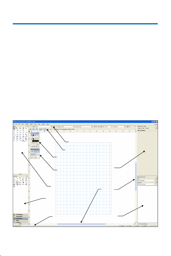
View bar
Tool bar
Attributes palette
Snapping palette
Basic tools
Tool Sets
2. From the menu, select Tools > Workspaces > Fundamentals. If the Funda-
mentals workspace is already active, select
it again to reset the interface. Position the
Navigation palette where shown, and examine key areas of the interface identified in the
following figure.
Object Info palette
Scroll bar
Message bar
10 | Vectorworks Fundamentals 2011 Getting St arted G uide
Page 11
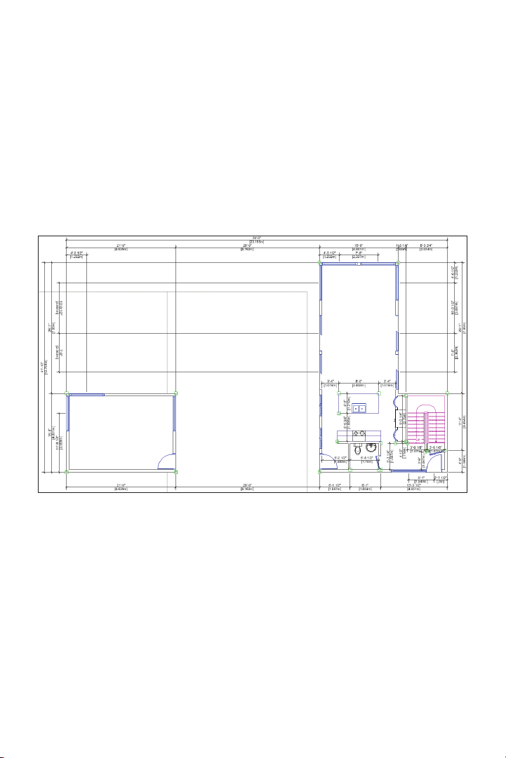
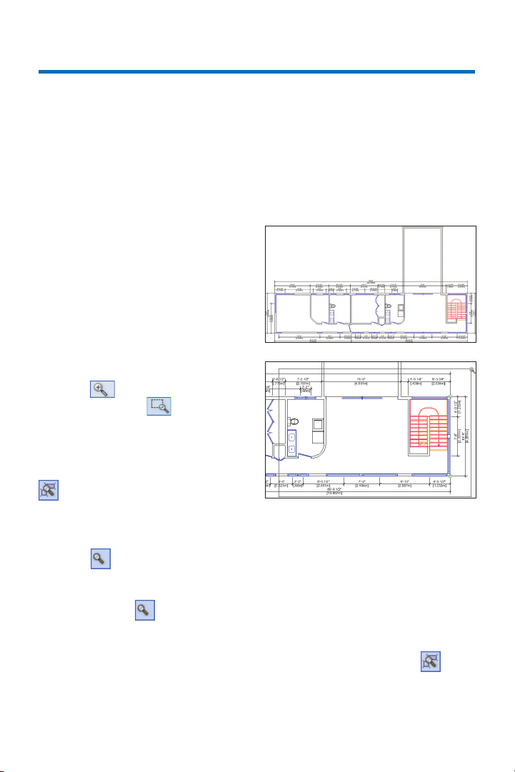
Opening the Starting File
Next, you open the supplied starting file of
a house design adapted from the awardwinning Dwell Home design by
Resolution: 4 Architecture.
Note: You examine the structure of this file in
Exercise 3.
3. Close any open files, and then from
the menu, select File > Open. In the Open
Vectorworks Drawing dialog box, open the
Data Set folder and open the read-only
GS-VWFx01.vwx file. The first floor plan is
displayed as shown. Keep the file open for
the next exercise.
Vectorworks Fundamentals 2011 Getting St arted G uide | 11
Page 12
Exercise 2: Adjusting
Preference Settings
In this exercise, you verify and adjust program preferences.
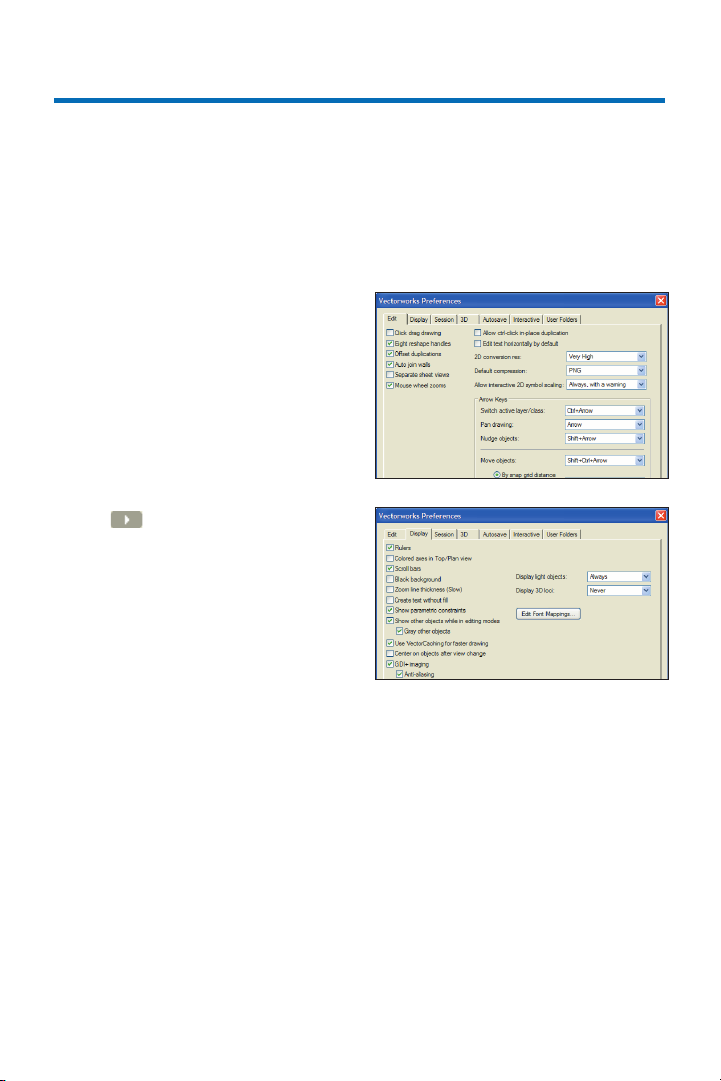
Adjusting Vectorworks
Preferences
Start the exercise by verifying or adjusting key application preference settings to
ensure proper exercise operation. Then turn
on Scroll bars to facilitate navigation, and
then you increase the maximum number of
undos so you can revert exercise steps if
necessar y.
1. Click on the far right side of the Tool
bar and select Vectorworks Preferences.
In the Vectorworks Preferences dialog box,
select the Edit tab, and then verify or adjust
settings as shown (Keep the dialog box open
for the next three steps.)
2. Select the Display tab, and enable the
Scroll bars option. Then verify or adjust
other settings as shown.
12 | Vectorworks Fundamentals 2011 Getting St arted G uide
Page 13
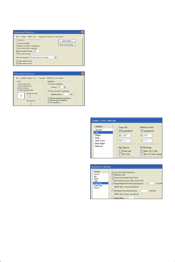
Adjusting Grid and
Smart Point Settings
5. Press Ctrl+8 to display the SmartCursor Settings dialog box. If a tip is displayed,
click OK, and then select Grid from the
Category list. Clear the Show Grid and Print
Grid checkboxes, and verify or adjust other
settings (.125” [3.18mm], 1/2” [12.70mm]) as
shown at top. From the Category list, click
Smart Point, and verify or adjust settings
as shown at bottom. Click OK to close the
dialog box and save the changes.
3. Select the Session tab, and then enter 100
in the Maximum number of undos field.
Verify or adjust other settings as shown.
4. Select the Interactive tab, and then
change the cursor’s Selection box size
and Snap box size. Verify or adjust other
settings as shown. Click OK to save the
settings and close the dialog box.
Vectorworks Fundamentals 2011 Getting St arted G uide | 13
Page 14

Turning off the Page
Boundary
Next, you turn off the page boundary for
clarity in the drawing area.
6. From the menu, select File > Page Setup.
In the Pages section of the Page Setup
dialog box, clear the Show page boundary
checkbox, as shown. Click OK to save the
settings, and notice that the page boundary
is no longer displayed in the drawing area.
Setting the Default
Font
Next, you adjust the default font.
7. From the menu, select Text > Font > Arial
to set the default font (if it’s not set to Arial
already), and then select Text > Size > 12 to
set the default font size to 12 point (if it’s not
set to 12 already).
Adjusting the Attributes
Palette Display
8. If your Attributes palette is not already
displayed, from the menu, select Window >
Palettes > Attributes, and then turn on Auto
Hide (Window Shade for Mac). Keep the
file open for the next exercise.
14 | Vectorworks Fundamentals 2011 Getting St arted G uide
Page 15

Section 2: Drawing
Organization
In one exercise, this section provides an overview of the following file structure features:
• Using the Organization Dialog Box (pg 16)
• Examining Layer Structure (pg 17)
• Examining Class Structure (pg 19)
• Examining Object Attribute Controls (pg 20)
In this exercise, you examine the structure of a sample architectural file so you can see how
the drawing objects are organized.
Vectorworks Fundamentals 2011 Getting St arted G uide | 15
Page 16
Exercise 3: Examining Key
Drawing Structure Features
In this exercise, you open an architectural sample file and examine the layer and class
structure. You then learn the basic control options for displaying object attributes.
Note: Due to the complex nature and permutations of drawing structure features and controls, this
exercise provides only an introductory overview. Refer to the nline Help for more detailed information.
Using the Organization
Dialog Box
Start the exercise by opening the Organization dialog box and then examining various
tabs and control features.
Note: The Organization dialog box provides
single-point viewing, creation, and modification
control of drawing structure elements.
1. From the menu, select Tools > Organi-
zation to display the Organization dialog
box. Select different tabs, and then examine
a few of the items listed on each tab. Notice
(as shown in the following examples) that:
• You can click an attribute column heading to sort the entire list (click the column
heading again to toggle the sort order).
• You can right-click an item or a blank area
inside the list to display the context menu.
• You will find different command buttons
for different tabs displayed on the bottom.
Keep the Organization dialog box open for
the next step.
Note: The References tab has no items listed
because there are no referenced files in this
sample drawing.
16 | Vectorworks Fundamentals 2011 Getting St arted G uide
Page 17
Examining Layer Structure
Next, you examine key design layer attri-
butes and controls and explore the structure
of design layers in this sample file.
Notes:
1) Design layers are primarily used as spatial
containers for creating drawing objects and/or to
control object stacking order.
2) Sheet layers are primarily used as a 2D-only
page layout environment for printing.
2. In the Organization dialog box, select the
Design Layers tab, and examine the following key layer attributes:
• Spatial attributes: the varying Z and ±Z
values define layer base heights (elevations)
and thicknesses, respectively
• Visibility attributes: visible, invisible,
gray, colors, and opacity
• Stacking order attribute: integers indicate the display order (or which objects are
on top of others; for example, number 1 is
on top of all others)
3) Layer color overrides are used for clarity in
the sheet layer viewports that you modify, start-
ing with step 5.
3. Click Cancel to close the Organization
dialog box without saving changes.
Next, you turn on visibility of layers in
sequential order, simultaneously in two
sheet layer viewports to expose the objects
that they contain. As you virtually rebuild
the design on-screen from the ground up,
you see exactly how layers act as spatial
containers in this file.
4. In the View bar:
• Click Saved Views, and then select the
Sheet Layer-Auxiliary Views saved view
from the drop-down list (as shown at below)
to activate it.
• Notice that the Sheet Layer-Auxiliary
Views sheet layer is now active, with 2 blank
viewports selected, as shown at bottom.
Notes:
1) This file structure was created with Vector-
works Architect’s setup commands.
2) This file uses layers primarily as spatial
containers for architectural elements on different
elevations.
Vectorworks Fundamentals 2011 Getting St arted G uide | 17
Page 18
5. In the Object Info palette:
• Notice that 2 viewports are selected (see
Note below), as shown below at left.
• Click Layers to display the Viewport
Layer Properties dialog box. Move the
dialog box so you can see both viewports,
and then turn on visibility of the Mod-
Slab-1 layer, as shown above at right. Click
Preview, and notice that floor objects in
the Mod-Slab-1 layer are displayed in both
viewports (in black color), as shown at
below Leave the Viewport Layer Properties
dialog box open for the next step.
Note: Sheet layer viewports are individual 2D
“live camera view” objects that reside on sheet
layers but display 2D and 3D drawing objects on
design layers. When you modify drawing objects
on a design layer, the viewport itself doesn’t
change, but it displays the design layer changes.
6. For each of the following layers—one at
a time, in the order listed—turn on visibility,
and then click Preview:
• Mod-Floor-1 (wall and architectural
element objects are displayed in red color,
as shown at top left)
• Mod-Slab-2 (floor objects are displayed
in green color, as shown at top right)
• Mod-Floor-2 (wall and architectural element objects are displayed in blue color, as
shown at bottom left)
• Mod-Roof (the roof object is displayed
in magenta color, as shown at bottom right)
7. Click OK to save the layer visibility
changes and close the Viewport Layer
Properties dialog box, and then press the X
key twice to clear the selection.
18 | Vectorworks Fundamentals 2011 Getting St arted G uide
Page 19

Examining Class Structure
Next, you examine key class attributes and
controls, and then you explore the class
structure of this sample file.
Note: Classes are primarily used to control display
properties and visibility of drawing objects.
8. In the View bar, click Saved Views, and
then select the Floor Plan-2 saved view from
the drop-down list to activate it. Notice that
the Mod-Floor-2 design layer is now active.
9. Press Ctrl+Shift+O for the Organization dialog box shortcut, and then select
the Classes tab. Notice that all attributes
for classes either control visibility or object
display, as shown.
10. Drag the Organization dialog box’s
lower left corner to reduce its size, and
then move it as high up on the screen as
possible. Scroll as necessary, and then for
each of the following classes—one at a
time, in the order listed—click in the Class
Name column to select the class. Change
the attribute as directed, and click Preview
to see the effect.
• Wall Exterior: Click Edit, and then
select any light gray Fill Color in the Edit
Class(es) dialog box (click the buttons at the
bottom of the color palette to display other
color palettes). Click OK to shade exterior
walls, as shown at left.
• Structural-Slab: Click Edit, and then
select any light beige Fill Color in the Edit
Class(es) dialog box (click the buttons at the
bottom of the color palette to display other
color palettes). Click OK to shade the floor,
as shown at center.
• Dimension: Change Visibility to Invisible
(click in the Invisible column) to hide the
dimensions, as shown at right.
Next, you change attributes or visibility of a
few classes so you can see how classes are
used in this file.
Tip: Double-click a class to open the Edit
Class(es) dialog box.
Vectorworks Fundamentals 2011 Getting St arted G uide | 19
Page 20
11. Click OK to close the Organization dialog
box and save the changes.
Tip: If one or more of your drawing objects has
disappeared in your own files, the problem may
be related to a class and/or layer assignment or
visibility issue. Turn on the Show/Snap/Modify
Others Layer Option, and then use the Custom
Selection command (with appropriate criteria)
to find it. You can then correct class and layer
properties if necessary.
Examining Object
Attribute Controls
Next, you examine object display controls in
the Attributes palette.
12. If necessary, click the Attributes palette
to expand it, and then examine the controls
for object fill and pen styles, opacity, line
style, and markers.
There are three primary methods you can
use to apply these attributes:
• Default: When no objects are selected,
the current settings are applied to all subsequently created objects. Default settings are
persistent, but you can change them at any
time when no objects are selected.
• By selection: When objects are selected,
any setting you change is only
applied to the current selection.
When you clear the selection, the prior default settings are
restored.
• By class The active class (or automatically assigned class) applies its settings to
objects created. An arrow icon indicates
“by class” settings.
Notes:
1) Certain types of
objects (such as walls)
provide their own control
of these attributes, and are
not affected by Attribute
palette settings.
2) You use the Attributes palette later in Exercise
5 (pg 28) and Exercise 11 (pg 57).
13. Close your file. Do not save changes.
20 | Vectorworks Fundamentals 2011 Getting St arted G uide
Page 21

Section 3: View and
Visibility Controls
In one exercise, this section covers the following processes for navigating drawings and
controlling the display of drawing objects:
• Zooming and Panning (pg 22)
• Changing Class and Layer Visibility Options (pg 24)
• Creating a Saved View (pg 25)
• Activating a Saved View (pg 25)
In this exercise, you continue working with the sample architectural file from Section 2 (pg 15)
as you practice using navigation and visibility controls in a Vectorworks drawing with multiple
layers and classes.
Vectorworks Fundamentals 2011 Getting St arted G uide | 21
Page 22
Exercise 4: Working with
View Controls
In this exercise, you learn how to navigate the drawing and control display of layers and
classes. You complete the exercise by creating a saved view.
Zooming and Panning
You start the exercise by using different
methods to control the display magnification.
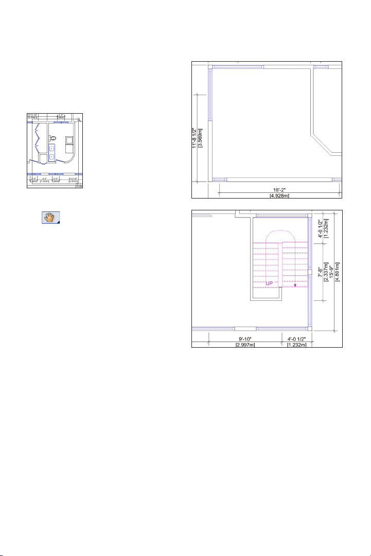
1. Open the GS-VWFx03.v wx file in the
Data Set folder. The file opens with the stair
object selected on the second floor plan, as
shown. Leave the stair selected for the next
two steps.
2. From the Basic tools palette, click the
Zoom tool . In the Tool bar, enable
Marquee Zoom Mode (if it’s not
already active), and then draw a marquee
from lower left to upper right to zoom in on
the area around the living room, as shown.
3. From the View bar, click Fit to Objects
. The view is adjusted to t the selected
stair object to the screen.
4. Press the X key twice to clear the
selection. From the View bar, click Zoom In/
Zoom Out , once, and then click it again
to zoom in on the center of the stair object.
5. Hold down the Alt key, and then click
Zoom In/Zoom Out twice to zoom out
so you can once again see the entire stair
object.
6. From the View bar, select 100% from the
Current Zoom drop down list to zoom out.
Tips:
1) You can also use your mouse wheel to zoom
in and out.
2) You can specify an exact value for the Current
Zoom magnification level. To do this, click the
Current Zoom value to highlight it, and then type a
new value. Press Enter to incorporate the change.
7. From the click Fit to Objects . Since
no object is selected, the view is adjusted to
fit all objects to the screen.
22 | Vectorworks Fundamentals 2011 Getting St arted G uide
Page 23
8. From the Basic tools palette, click the
Zoom tool , and then zoom in on the hall
bathroom and hallway, as
shown.
Next, you use different
methods to move the
view.
9. From the Basic tools palette, click the Pan
tool . To pan to the left side of the floor
plan, move the cursor to the left side of the
screen, and hold down the left mouse button
and drag straight across to the right side of
the screen. Repeat the process as necessary until you reach the left end of the floor
plan (shown at right top). Reverse the direction to pan to the right until the stair object is
visible, as shown at right bottom.
10. Experiment panning the drawing using
the scroll bars:
• Drag the bars to move the view up,
down, left, or right.
• Click the arrows on the ends of the
scroll bars to pan in smaller increments.
• Click the blank area between the
scroll bars and arrows to pan one screen
width at a time.
Vectorworks Fundamentals 2011 Getting St arted G uide | 23
Page 24
Changing Class and
Layer Visibility Options
Next, you adjust layer visibilities in the
Organization dialog box, and then you
change options for class and layer visibility.
11. If any objects are selected, press the
X key twice to clear the selection. Press
Ctrl+6 for the Fit to Objects shortcut.
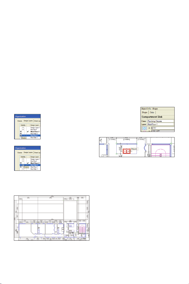
12. Press Ctrl+Shift+O for the Organization
dialog box shortcut. Select the Design Layers tab, and then:
• Turn on visibility of the Mod-Floor-1
layer (click in the Visible
column), as shown
• Turn off visibility of the
Mod-Slab-2 layer (click in
the Invisible column), as
shown
• Click OK to close the Organization dialog
box and update the display, as shown below
13. Press the X key, and then try to select
(left-click) the kitchen sink on the first floor.
Although the cursor previews the sink’s
snap points, you can’t select it because the
Show/Snap Others layer option is currently
active. From the menu, select View > Layer
Options > Show/Snap/Modify Others.
Move your cursor over the sink and notice
that the pre-selection highlight is now
displayed, as shown below. Select the sink
and notice the Class
and Layer properties
in the Object Info
palette’s Shape pane,
then press the X key
twice to clear the selection.
Warning: Use caution when the Show/Snap/
Modify Others layer option is active. You should
only use this option temporarily (do not enable
this option in your saved views) until you become
more comfortable using Vectorworks.
24 | Vectorworks Fundamentals 2011 Getting St arted G uide
Tip: You can also right-click an object on an
inactive layer or class and use the Force Select
context menu command to select it, but this
command also changes the active layer.
Page 25
14. Right-click the drawing background
(outside the exterior dimensions), and then
select Layer Options > Gray/Snap Others
from the context menu. Objects on the
first floor (the Mod-Floor-1 layer) are now
grayed, as shown.
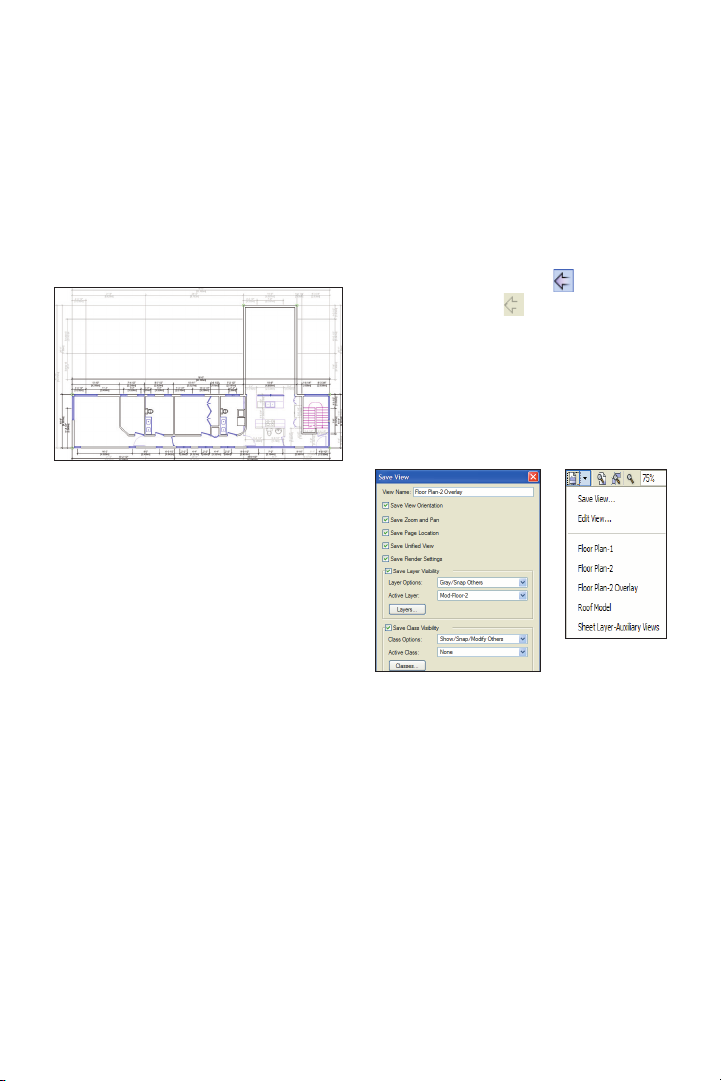
Creating a Saved View
Next, you create a saved view based on the
current display settings.
15. From the menu, select View > Save
View. In the Save View dialog box, adjust
the settings as shown, and then click OK to
save the view. In the View bar, click Saved
Views, and notice that the new view is now
displayed in the list, as shown at right.
Activating a Saved View
Next, you revert previous views, and then
you activate the view you just saved to verify
that all settings are restored.
16. In the View bar:
• Click Previous View repeatedly
(until it’s grayed out ) to restore the view
that was active when you opened the file.
• Select Floor Plan-2 Overlay from
the Saved Views drop-down list, and notice
that the view is restored exactly as you
configured it.
17. Close your file. Do not save changes.
Vectorworks Fundamentals 2011 Getting St arted G uide | 25
Page 26

Page 27

Section 4:
2D Drawing Tools
In two exercises, this section covers the following processes for drawing basic 2D objects:
• Drawing Rectangles (pg 28)
• Drawing Lines (pg 29)
• Drawing Arcs (pg 31)
• Drawing a Circle (pg 32)
• Drawing an Oval (pg 32)
• Drawing Polygons (pg 33)
• Drawing a Polyline (pg 35)
In these exercises, you use basic 2D drawing tools to start drawing
the outline and components of a remote control transmitter.
After completing the exercises in the section, your drawing should look
similar to the following figure.
Notes:
1) You develop the remote control transmitter design over the next eight
(continuing) exercises.
2) For educational purposes, most drawing operations in these exercises
are grouped by similar functions. As a result, you don’t draw many of the
remote control’s components in the normal order of creation—from star t to
finish. For these cases, you draw a portion in one exercise and then continue
drawing or modifying geometry in one or more subsequent exercises.
Vectorworks Fundamentals 2011 Getting St arted G uide | 27
Page 28

Exercise 5: Drawing 2D Objects
In this exercise, you start laying out the remote control components by drawing basic 2D
objects. The completed exercise is shown in the following figure.
Drawing
Rectangles
You start the exercise by
drawing different types of
rectangles to represent
various components of the
remote control.
1. Open the GS-VWFx05Step01.vwx file in the
Data Set folder. The file
opens with some construction geometry (gray lines),
a rectangle, and a line
already drawn.
Next, you use the Rounded Rectangle
tool to draw the remote control’s LED
display panel.
2. From the Basic tools
palette, double-click the
Rounded Rectangle
tool to display the
Create Object dialog
box. Change the settings (2.000 [50.80mm],
1.500 [38.10mm], .250
[6.35mm]; ignore X and
Y settings) as shown
at right.
Important: Make sure
that the Box Position
(fixed point) is set to center and that the Position
At Next Click option is
enabled. Click OK, and
move the cursor over the
gray vertical centerline
and press the T key to
set a surface snap. Snap
(left-click when the Surface SmartCursor cue is
displayed) to the centerline approximately
where shown at right, to create the rounded
rectangle, as shown below.
28 | Vectorworks Fundamentals 2011 Getting St arted G uide
Page 29

Next, you use the Rectangle tool to draw
the remote control’s enter button (at the
center of the directional buttons).
3. From the Basic tools
palette, double-click the
Rectangle tool
to display the Create
Object dialog box.
Change the settings
(.600 [15.24mm], .300
[7.62mm]; ignore X and
Y settings) as shown
at left.
Important: Make sure
the Box Position (fixed
point) is set to center,
and the Position At
Next Click option is
enabled. Click OK and
then snap to the center
of the large rectangle
(shown at right), to create the small rectangle.
Note: You can alternately use Center and Corner
Rectangle Mode to draw the rectangle by
snapping to the center of the large rectangle and
entering the appropriate ±X and ±Y values in the
floating data bar. You can also use this method in
your own designs to dynamically draw centered
rectangles without the floating data bar. If you
choose to try this, activate Rectangle Mode
(when nished) for the next step.
Next, you draw a rectangle to form the base of
an arrow indicator on the directional buttons.
4. With the Rectangle tool still active, click
the lower left and upper right corners to create another rectangle approximately where
shown at left. In the Object Info palette,
select the Shape tab (if it’s not already
active). Change the Width to .120 [3.05mm]
and the Height to .200 [5.08mm], and then
press Enter to resize the rectangle, as
shown at right.
Drawing Lines
Next, you draw lines to divide the directional
controls and provide boundaries or guidelines that you use later in this exercise and in
Exercise 6 (pg 33).
5. From the Basic tools palette, click the
Line tool . Snap to bottom end of the
rounded rectangle’s top left arc, as shown at
left. Hold down the Shift key to constrain the
line vertically, and then click directly above
the start point to complete the line, approximately where shown at right.
Vectorworks Fundamentals 2011 Getting St arted G uide | 29
Page 30

6. With the Line tool still active, snap to the
top left corner of the existing rectangle, and
then hold down the Shift key to constrain the
line horizontally. Then snap to the angled
guideline to complete the line, as shown at
left. Repeat the process to create another
horizontal line on the opposite side, as
shown (highlighted) at right.
7. With the Line tool still active, create a
guideline at a 45° angle by snapping to the
bottom left corner of the enter button, and
then using the Shift key, as shown at left
(make sure the line extends outside the large
concentric rectangle). Repeat the process
to create two more guidelines (for a total of
three) at 45° angles, as shown at right.
8. With the Line tool
still active, snap to
the top left corner of
the profile guideline,
as shown at left. Start
moving your cursor
toward the right. Enter
2 [50.80mm] to activate
the floating data bar’s L
field and set the value.
Then press Tab (a
circular constraint indicator is displayed) and
enter 8 for the floating
data bar’s A field (angle). Press Enter once
to display the constraint (shown above), and
then press it again to create the angled line,
as shown at right.
Next, you use the floating data bar to
draw the top (transmitter) edge of the
remote control.
30 | Vectorworks Fundamentals 2011 Getting St arted G uide
Tip: You can check the length and angle of this
line (when it’s selected) by clicking the polar
coordinate button in the Object Info palette.
If you do this, be sure to click the Cartesian
coordinate button when nished to ensure
proper operation of exercises in this tutorial.
Page 31

Drawing Arcs
Next, you turn off object fills in the Attributes
palette and then draw arcs for the remote
control’s left edge and for the top and bottom edges of the directional controls.
9. Press the X key
twice to clear the
selection. In the Attributes palette, change
the Fill Style to None,
as shown at top. From
the Basic tools
palette, click the
Arc tool . In
the Tool bar, enable
Arc by 2 Points
and a Specied
Radius Mode
. Click the bottom vertex of
the remote control’s left edge
(angled gray line), and then
click the top vertex (the start
point of the last line you drew).
In the Arc Radius dialog box,
enter 45 [1143.00mm] for
the Radius value (shown at
center), and then click OK to
create the arc, as shown at
bottom.
Notes:
1) You change the Fill Style to None to prevent
arcs and subsequent drawing objects from ob-
scuring other drawing and construction geometry.
2) You enter precise radius values for all arcs
in this exercise to ensure accuracy. In your own
designs, you can dynamically determine an
appropriate radius by using the Arc tool’s Arc by
2 Points and a Point on Arc Mode , which
you use later in Exercise 8 (pg 41).
10. With the Arc tool
still active, repeat
the process to draw
an arc (from left to
right) with a radius
of 9 [228.60mm] on
the endpoints of the
remote control’s top edge (the line at an 8º
angle), as shown.
11. With the Arc tool
still active, repeat
the process to draw
an arc (from left to
right) with a radius
of 4.88 [123.95mm] on the top edge of the
large concentric rectangle. Then draw an
arc (from right to left) on the bottom edge
with the same radius, as shown (highlighted
for clarity).
Note: You would normally use one of the copy
operations to create the bottom arc by duplicating
the top arc, but you draw it in this exercise to
practice creating arcs.
Vectorworks Fundamentals 2011 Getting St arted G uide | 31
Page 32

Drawing a Circle
Next, you draw a circle for the center function button.
Drawing an Oval
Next, you draw an oval to represent the
lower left keypad button.
12. From the Basic tools palette, click the
Circle tool . In the Tool bar, enable Circle
tool . In the Tool bar, enable Circle
by Radius Mode . For the center of
the rounded rectangle (shown at left), and
then start moving the cursor and type .19
[4.83mm] to set the floating data bar’s L
(radius) field. Press Enter twice to complete
the .380 [9.65mm] diameter circle, as shown
at right.
Note: You move this circle into its correct
position later in Exercise 8 (pg 41).
13. From the Basic tools palette, click the
Oval tool . In the Tool bar, enable Oval
by Box Mode . Draw a diagonal line
from lower left to upper right to create an
oval, approximately where shown at top. In
the Object Info palette, change the Width to
.430 [10.92mm], and change the Height to
.300 [7.62mm]. Then press Enter. Press the
X key twice to clear the selection, and examine the completed oval, as shown at bottom.
14. Save the file.
32 | Vectorworks Fundamentals 2011 Getting St arted G uide
Page 33

Exercise 6: Drawing Multi-Segment
2D Objects
In this exercise, you continue laying out remote control components by drawing polygons
and polylines. The completed exercise is shown in the following figure.
You start this exercise by using the 2D
Polygon tool to draw a triangle that you use
as an arrowhead indicator for the directional
buttons.
1. Open the GS-VWFx05.vwx file in the
Data Set folder.
2. Zoom in on the area shown at left. From
the Basic tools palette, click the 2D Polygon
tool . Then in the Tool bar, enable
Polygon From Vertices Mode . Start
the polygon by clicking approximately where
point 1 is shown (at center). Hold down the
Shift key to constrain the cursor horizontally,
and then click approximately where point
2 is shown. Click point 3, and then click
the start point again—when the Endpoint
SmartCursor cue is displayed—to close the
polygon (see Notes below figure), as shown
at right.
3
1
2
2) Do not be concerned about the accuracy
or the intentional asymmetrical shape of your
polygon because you reshape it later in Exercise
7 (pg 38).
Next, you temporarily turn off visibility of a
class and then modify the outer concentric
rectangle to facilitate creation of the directional buttons.
3. From the View bar, click Classes . In
the Organization dialog box, turn off visibility
of the Outline class, as shown, and then
click OK.
Notes:
1) The polygon closes and terminates when
you click the start point. If your polygon doesn’t
close, press the Delete key to undo the last seg-
ment, and then click the start point again.
Vectorworks Fundamentals 2011 Getting St arted G uide | 33
Page 34

4. Press the X key, and then select the
outer concentric rectangle (only the rectangle should now be selected), as shown.
From the menu, select Modify > Decompose. In the Object Info palette, notice that
lines are now selected. Hold down the Shift
key, and click both vertical lines to remove
them from the selection (2 lines should
now be selected), as shown left. Press the
Delete key to remove the horizontal lines
from the drawing, as shown right.
Next, you use the Polygon tool to create
the directional buttons from the inner boundaries of other drawing objects.
5. Press the 8 key for the 2D Polygon
shortcut, and then enable Polygon From
Inner Boundary Mode in the Tool
bar. Click anywhere inside the “left”
directional button’s boundary lines to create
the polygon, as shown right. Click again
anywhere inside the “up” directional button’s
boundary lines to create another polygon,
as shown left.
6. From the View bar, click Classes . In
the Organization dialog box, turn on visibility
of the Outline class, and then click OK.
34 | Vectorworks Fundamentals 2011 Getting St arted G uide
Page 35

Drawing a Polyline
Next, you draw a polyline by cubic vertices
to create curvature that is more pointed
than an arc for the top edge of the volume/
channel buttons.
7. From the Basic tools palette, click the
Polyline tool . In the Tool bar, enable
Cubic Vertex Mode , and then specify
the start point by snapping to the left vertex
of the left horizontal guideline, as shown.
For the midpoint, move the cursor over
the gray vertical centerline and press the
T key to set a surface snap. Snap to the
centerline, approximately where shown left
Complete the polyline by double-clicking the
right vertex of the right horizontal guideline,
as shown right.
Next, you hide some of the construction
lines by changing their class property to the
Geometry Ref class (which is already set
to invisible).
8. Press the X key twice to clear the current
selection, and then hold down the Shift key
and select the right horizontal guideline,
and all three angled lines that divide the
directional buttons (if you accidentally select
one of the other objects, select it again to
remove it from the selection set), as shown.
In the Object Info palette, select
Geometry Ref from the Class drop-down
list, as shown, to hide the construction lines.
Note: You draw a multi-segment polyline using
different modes in the “Cropping a viewport “
section in Exercise 16 (pg 78).
Tip: Use this method in your own designs to
preserve construction geometry in case you need
to modify the design later.
9. Save the file.
Vectorworks Fundamentals 2011 Getting St arted G uide | 35
Page 36

Page 37

Section 5: Manipulating
and Modifying Objects
In six exercises, this section covers the following commonly used processes for modifying,
moving, and duplicating existing drawing objects:
• Moving a Reshape Handle (pg 38)
• Using the 2D Reshape Tool (pg 39)
• Interactively Scaling Objects (pg 39)
• Copying Objects (pg 41)
• Rotating Objects 90 Degrees (pg 43)
• Moving and Nudging Objects (pg 43)
• Offsetting Objects (pg 44)
• Creating the Volume Button with a
Polygon Fill (pg 45)
• Creating a Duplicate Array (pg 45)
• Mirroring Objects (pg 46)
• Resizing an Arc (pg 46)
• Duplicating Objects Along a Path (pg 47)
• Creating Rotated Copies of Objects
(pg 48)
• Using the Move by Points Tool (pg 48)
• Creating the Outer Function Button with
a Polygon Fill (pg 49)
• Creating Groups (pg 50)
• Aligning Objects (pg 51)
• Combining Objects (pg 52)
• Subtracting Objects (pg 53)
• Intersecting Objects (pg 53)
• Clipping Objects (pg 54)
• Creating Fillets (pg 55)
• Creating Chamfers (pg 56)
• Hiding Construction Geometry (pg 57)
• Creating Objects for Color Fills (pg 58)
• Changing Object Stacking Order (pg 59)
• Modifying Object Attributes (pg 60)
• Transferring Object Attributes (pg 62)
• Creating a Symbol (pg 63)
• Inserting a Plug-In Object (pg 65)
In these exercises, you complete the remote
control transmitter design by modifying and/
or duplicating the 2D geometry you created in
Section 4 (pg 27). You then continue working
with the sample architectural file from Section
3 (pg 21) as you learn how to create and insert symbols. After completing the exercises
in the section, your drawings should look
similar to the following figures.
Vectorworks Fundamentals 2011 Getting St arted G uide | 37
Page 38

Exercise 7: Resizing and
Reshaping Objects
In this exercise, you use different methods to
change the orientation, size, and shape of
existing objects. The completed exercise is
shown in the following figure.
Moving a Reshape Handle
You start the exercise by moving a reshape
handle to change the left horizontal guideline to a vertical guideline.
1. Open the GS-VWFx06.v wx file in the
Data Set folder.
2. From the Basic tools palette, click the
Selection Tool . In the Tool bar, make
sure Single Object Interactive Scaling
Mode is active. Select the left horizon-
tal guideline, and then click the left vertex to
“pick it up,” as shown left Move the cursor
over the left edge of the left directional
button, and then press the T key to set a
surface snap. Click the surface extension
line—when the Vertical SmartCursor cue
is displayed—near the bottom of the edge
of the display (approximately where shown
at center) to change the line’s orientation to
vertical, as shown at right.
38 | Vectorworks Fundamentals 2011 Getting St arted G uide
Page 39

Using the 2D Reshape Tool
Next, you reshape the arrowhead indicator
for the directional buttons.
3. Zoom in on
the area shown
at right. Press the
X key twice, and
then double-click
the arrowhead
polygon. Notice that all of the polygon’s
reshape handles are now displayed directly
on it. Also notice that the 2D Reshape tool
(in the Basic tools palette) is now active. In the Tool bar, enable Move Polygon
Handles Mode , and then click the
bottom center reshape handle to “pick it
up.” Click the center of the rectangle to
reshape the edge (and center it with the
rectangle), as shown at left. Click the arrow point reshape handle, and then click
the top center point of the rectangle. The
arrow is now symmet ric, as sho w n at right .
the new vertex and change the triangle
to a wedge, as shown at right. Leave the
polygon selected for the next step.
Interactively
Scaling Objects
Next, you use the Selection Tool to scale
the arrowhead indicator.
5. Press the X key to activate the Selection
Too l. Notice that reshape handles are now
displayed on the polygon’s bounding box.
Click the top center reshape handle, and
then click above—and to the right of—the
point, as shown.
4. With the 2D Reshape tool still active,
enable Add Vertex Mode in the Tool
bar. Click the bottom center reshape handle
(shown at left) to add a vertex. Hold down
the Shift key and move your cursor slightly
above the point, and then click to position
Notice that moving a
bounding box reshape
handle maintains the
arrowhead’s symmetry (even though you
clicked to the right).
Vectorworks Fundamentals 2011 Getting St arted G uide | 39
Page 40

Select the rectangle, and then move its top
center reshape handle to the interior wedge
vertex, as shown at left. Shorten the arrow’s
tail by moving the rectangle’s bottom center
reshape handle, approximately where
shown at right.
6. In the Tool bar, enable Unrestricted
Interactive Scaling Mode . Hold down
the Shift key and click the arrow wedge
to add it to the current selection. In the
Object Info palette, verify that 2 objects are
selected. Click the arrow’s top right reshape
handle and then move the cursor and click
to complete the reshape operation, approximately where shown at left. Notice that both
objects are now scaled together. Experiment with changing the overall shape of the
arrow by moving different reshape handles,
as shown in the next two gures. When
nished experimenting, reset the Selection
Too l’s default mode by enabling Single
Object Interactive Scaling Mode
in the Tool bar. Click Previous View in
the View bar so you can see all resized and
reshaped objects.
Tip: When you already know the exact size of a
completed triangle in your own designs, you can
use the Triangle tool to draw it directly.
You can optionally create a temporary line—and
use its vertices as snap points to index the
triangle’s first side—by drawing a line with the
Line From Center Mode .
7. Save the file.
40 | Vectorworks Fundamentals 2011 Getting St arted G uide
Page 41

Exercise 8: Moving and
Copying Objects
In this exercise, you use a variety of precise and dynamic methods
to move or copy existing drawing objects. The completed exercise is
shown in the following figure.
Copying Objects
You start the exercise by moving the arrow
objects into the “up” directional button.
1. Open the G S -VWFx 07.v w x file in the
Data Set folder. The file will open with the arrow wedge and rectangle already selected.
2. Press the X key to activate the Selection
Too l. Hold down the left mouse button on
the top edge of the arrow rectangle, and then
start moving the cursor to “drag” both arrow
objects. Release the mouse button when the
arrow objects are inside the “up” directional
button, approximately where shown.
Next, you use the
“Ctrl+drag” method to
copy the arrow objects
into the “left” directional
button.
3. Start dragging the
arrow objects to the
left, and then hold down
the Ctrl key (notice a
plus sign is displayed near the cursor to
indicate copy mode is active) and release
the mouse button to copy the arrow objects
when they are inside the “left” directional
button, approximately where shown.
Vectorworks Fundamentals 2011 Getting St arted G uide | 41
Page 42

Next, you copy the keypad
oval and then resize and
rotate it for the first top
power button.
the X key twice to clear the
selection, and examine the
completed power button, as
shown at right.
4. Press the X key twice to
clear the current selection,
and then press Ctrl+6 to
display all drawing objects.
Use the Ctrl+drag method
to copy the keypad button
(oval) to the top of the remote control, approximately where shown at left. In
the Object Info palette,
change the Width (.200 [5.08mm]), Height
(.400 [10.16mm]), and Rotation (-60.00º) values, as shown, and then press Enter. Press
Tip: In addition to resizing the
oval, you can also rotate it
(and many other 2D objects)
dynamically with the Selection
Too l by pressing the Alt key
and dragging a corner reshape
handle.
Next, you copy the center
function button to create a
round button for the keypad.
5. Use the Ctrl+drag
method to copy the center
function button (circle) to
the center of the keypad
oval, as shown at left. Click
the circle’s radius reshape
handle, and then snap it to
the oval’s top center point
to resize the circle’s diameter to match the oval’s
height (.300 [7.62mm]),
as shown
42 | Vectorworks Fundamentals 2011 Getting St arted G uide
Note: You copy and reposition
the round keypad button later
in this exercise.
Page 43

Rotating Objects
90 Degrees
Next, you rotate the copied arrow objects 90
degrees to orient them correctly for the “left”
directional button.
6. Press the X key twice to clear the selection, and then hold down the Shift key and
select the arrow wedge and rectangle in the
left directional button, as shown at left. From
the menu, select Modify > Rotate > Rotate
Left 90º. The arrow objects now point to
the left, as shown at right. Leave the arrow
objects selected for the next step.
Moving and Nudging
Objects
Next, you move the arrowheads by the center point of the rectangular base to center
them with the directional buttons.
7. Start dragging both arrow objects by
the bottom center point of the rectangle (as
shown at left), and then release the mouse
button on the right midpoint of the “left”
directional button, as shown at right.
Hold down the
Shift key and then
press the Left
arrow key repeat-
edly to nudge the
arrow into position, approximately where
shown above.
8. Press the X key twice to clear the
selection, and then hold down the Shift key
and select both arrow objects for the “up”
directional button. Repeat the centering
and nudging process (with the Shift and
Up arrow keys) to position the objects approximately where shown.
Next, you move the polyline to index its
position relative to the top edge of the
directional button’s arc, and then you use
the Move command to raise the polyline and
function button (circle) into position.
Vectorworks Fundamentals 2011 Getting St arted G uide | 43
Page 44

9. Drag the curved polyline by its midpoint
to the midpoint of the “up” directional button’s arc, as shown.
10. Hold down the Shift
key, and then select the
function button (circle) to
add it to the current selection (2 objects should now
be selected).
From the menu, select
Modify > Move > Move. In
the Move Selection dialog
box, change the Y Offset value to .440
[11.18mm] (as shown), and then click OK to
move both objects, as shown at right.
Offsetting objects
Next, you offset several objects to either
create new boundary or centerline objects,
or to change the original object’s size.
Enter. Hold down the Alt key, and then select the arc that forms the top curved edge
of the remote control outline. Release the
Alt key, and then click below the arc to offset
it (.400 [10.16mm] to the inside) to create
the power switch array centerline, as shown
below at left. For the following offsets, use
the temporary Alt key method to select each
object, and start each offset operation in the
Too l ba r by:
• Changing the Distance to .060
[1.52mm] and pressing Enter. Offset the
arc (click it to the right of the “up” functional
button, and offset it to the outside) at the top
of the directional button rectangle to create
the lower boundary for the volume button,
as shown highlighted in the next figure.
• Changing the Distance to .020
[.51mm] and pressing Enter. Offset the vertical centerline (to the left) to create the right
boundary for the volume button, as shown
highlighted in the next figure.
• Enabling Offset Original Object
Mode . Offset the “left” and “up” direc-
tional buttons, and then the enter button
(.020 [.51mm] to the inside) to resize them,
as shown highlighted at right.
11. From the Basic tools palette, Offset tool
. In the Tool bar, enable both Offset by
Distance Mode and Duplicate and
Offset Mode , and then change the
Distance value to .400 [10.16mm] and press
44 | Vectorworks Fundamentals 2011 Getting St arted G uide
Page 45
Creating the Volume
Button with a Polygon Fill
Now that all boundary objects are in place,
you create a polygon for the volume button.
12. From the Basic
tools palette, click
the 2D Polygon tool
. In the Tool
bar, enable Polygon
From Inner Bound-
ary Mode . Click anywhere inside the
volume button boundaries to create the
polygon, as shown.
13. Press the X key twice to clear the selec-
tion, and then carefully select only the offset
centerline (the offset line that formed the
right boundary of the volume button), and
then press the Delete key to remove it from
the drawing (but do not delete the remote
control centerline).
Creating a Duplicate Array
Next, you create a rectangular array of the
oval-shaped button.
14. Select the oval keypad
button (do not select the
round button inside it).
From the menu, select
Edit > Duplicate Array.
In the Duplicate Array
dialog box, adjust settings
(.600 [15.24mm], .500
[12.70mm]) as shown
above, and then click OK
to create the keypad array, as shown at right.
Note: Do not be concerned if your keypad button
array is not centered; you align them with other
components later in this exercise.
Vectorworks Fundamentals 2011 Getting St arted G uide | 45
Page 46
Mirroring Objects
Next, you use the Mirror tool to create
opposite-hand copies of the remote control’s left edge and volume button.
Resizing an Arc
Next, you use the offset arc’s reshape
handles to extend it to the remote control’s
right and left edges.
15. Press the X key twice, and then hold
down the Shift key and select the volume
button (polyline) and the remote control’s
left edge (arc), as shown at left. From the
Basic tools palette, click the Mirror tool
, and then enable Duplicate and
Mirror Mode . Snap to top and bottom
endpoints of the remote control’s centerline
to specify the mirror line and create mirrored
copies of the objects. Press the X key twice
to clear the selection, and examine the mirrored copies, shown at right.
16. Select the arc
offset from the top
edge, as shown at
top. Click the left
reshape handle,
and then move your
cursor over the left
edge of the remote
control (where the
arc is farthest away
from other objects,
and no Smart
Cursor extensions
are displayed) and press the T key to set a
surface snap on the edge. Click the edge
when the Surface/Tangent SmartCursor cue
is displayed, as shown at top, to resize the
arc, as shown at center. Repeat the process
to extend the arc’s opposite end (see Note
below figure), as shown at bottom.
Note: You may need to press the Z key to acti-
vate the snap loupe so you can temporarily zoom
in and select the right edge with the Sur face/
Tangent SmartCursor cue.
46 | Vectorworks Fundamentals 2011 Getting St arted G uide
Now that the arc is flush with the left and
right edges, you shorten the arc (and keep
it centered) by using equations to change
the Start and End angle values in the Object
Info palette.
Page 47
17. In the Object Info palette, enter +2 (to
add 2 degrees) at the end of the Start value.
Press Enter to incorporate the change,
and notice that the arc is now shorter on
the right side, as shown at left. Repeat the
process to subtract 2 degrees (enter -2)
from the End value, and then press Enter
to shorten the left side of the arc, as shown
at right.
Duplicating Objects along
a Path
Next, you duplicate the power button along
the offset arc path to create an array that
follows the curvature of the top edge.
18. Hold down the
Shift key and select
the power button
(rotated oval) to
add it to the current
selection (two
objects should now
be selected). From
the menu, select
Edit > Duplicate
Along Path. In the
Duplicate Along Path
dialog box, adjust
settings as shown at
top, and then click
OK to create the duplicates. Press the X key
twice to clear the selection, and examine the
power button array, as shown at bottom.
Notes:
1) The position of the rotated oval (before the
duplication) does not affect the results.
2) You use the Duplicate Along Path com-
mand instead of creating a circular array to
evenly distribute the power button copies along
the path.
Vectorworks Fundamentals 2011 Getting St arted G uide | 47
Page 48

Creating Rotated Copies
of Objects
Next, you use the Rotate tool to copy
multiple objects 180 degrees.
19. Hold down the Shift key and select the
volume and channel buttons, the “left” and
“up” directional buttons, and all four arrow
objects, as shown below (in the Object Info
palette, verify that 8 objects are selected).
From the Basic tools palette, click the
Rotate tool . In the tool bar, enable
Duplicate and Rotate Mode . For
the center of rotation, snap to the center of
the enter button, and then hold down the
Shift key, and click to the right of the first
point (approximately where shown in the
next figure) to set the reference angle. Hold
down the Shift key, and then click on the
other side of the center point (approximately
where shown in the next figure) to specify
the new angle and create the rotated copies, as shown in the next figure.
Using the Move by
Points Tool
Next, you use the Move by Points tool to
move the circular keypad button, and then
you use Distribute Mode to create two
copies and complete the new bottom row of
circular buttons.
20. Press the X key
twice to clear the selection, and then select
the circular keypad
button (inside the lower
left keypad oval button).
From the Basic tools palette, click the Move by
Points tool . In the
Tool bar, enable Move
Mode , and then
click Move by Points
Preferences .
Adjust settings as shown
at top, and then click
OK. For the start point,
snap to the center of the oval directly above
the circle in the next row, and then snap to
the center of the circle to move it down and
maintain equal row spacing, as shown in
the next gure. In the Tool bar, enable Distribute Mode , and then click Move by
Points Preferences . Adjust settings
as shown in the next figure, and then click
OK. Snap to the center of the lower left oval,
and then snap to the center of the lower right
oval. The copies are distributed over the
selected distance and now match the keypad
column spacing, as shown at bottom.
48 | Vectorworks Fundamentals 2011 Getting St arted G uide
Page 49

Next, you use the Move by Points tool to
copy the volume button’s profile geometry
(arc and polyline).
21. Press the X key
twice to clear the selection, and then hold down
the Press Shift+M for
the Move by Points tool
shortcut, and then look at
the Tool bar while pressing the U key two times
to cycle through options
until Move Mode
is enabled. Click Move
by Points Preferences
, and adjust settings
as shown at center, and
then click OK.
Snap to the top center
point of the polyline (the
Fix SmartCursor cue is
displayed) to specify the
start point. Hold down the Ctrl key to activate
copy mode, and then snap to the top center
of the circular function button to complete
the copy operation. Press the X key twice to
clear the selection and examine the copied
objects, as shown at bottom
Tip: Press the U key to cycle through modes for
all tools.
Note: You can keep the Retain option enabled if
you prefer, but you may find it easier to keep the
default “move” behavior and use the Ctrl key to
activate copy mode.
Creating the Outer Function
Button with a Polygon Fill
Next, you extend the arc to form the bottom
boundary for the fill operation, and then you
extend the polyline by drawing a short line
segment to form the top boundary for the fill
operation.
22. Select the arc
you just copied (that
forms the bottom
boundary of the outer function button),
and then click the left
reshape handle and
click again outside of
the remote control’s
left edge to lengthen
the arc, approximately where shown
at top Press the 2
key for the Line tool
shortcut. Snap to the
endpoint of the polyline, and then click approximately where shown at center to draw
a parallel line that terminates outside of the
remote control, as shown at bottom.
Notes:
1) You create an extension line because the
Connect/Combine tool doesn’t work with cubic
vertex polyline objects, and other reshaping
methods change the curvature, which for this
design is intended to match the curvature of the
volume button.
2) In this case, a parallel line is sufficiently
Vectorworks Fundamentals 2011 Getting St arted G uide | 49
Page 50

accurate for the short gap. If you need to match
curvature more precisely or over a longer dis-
tance, draw an arc using Arc by 2 Points and a
Point on Arc Mode, and then snap all arc points
on the polyline near the end you want to extend.
You can then adjust the arc’s reshape handles
accordingly.
Now that all boundary objects form a closed
area, you create a polygon for the outer
function button.
23. Press the 8 key for the 2D Polygon
tool shortcut. In the Tool bar, make
sure Polygon From Inner Boundary Mode
is still active. Click anywhere inside
the function button boundaries to create the
polygon, as shown at left. Press the X key
twice to clear the selection, and then hold
down the Shift key and select the function
button’s construction objects (vertical line,
polyline, arc, and extension line). In the
Object Info palette, select Geometry Ref
from the Class drop-down list to hide them,
as shown at right.
Creating Groups
Next, you create groups of objects so you
can align the groups with each other.
24. Draw a selection marquee from lower
left to upper right around all 15 oval and
round keypad buttons, as shown below at
left. From the menu, select Modify > Group
to create a single group object from all 15
buttons. Repeat the marquee selection
process to create three more groups from
the following objects:
• The directional buttons, and all four
volume and channel buttons (also include
the construction geometry, except for the
vertical guide line), as shown in the next
figure.
• The outer function button and the
circular function button, as shown in the
next figure.
• The four power buttons (ovals) at the
top of the remote control.
50 | Vectorworks Fundamentals 2011 Getting St arted G uide
Important: Hold down the Shift key and select
the arc centerline to remove it from the selection
after you draw the marquee (as shown) and
before you create the group.
Page 51

Aligning Objects
Next, you lock the position of some components, and then you distribute and align the
objects to place them in their final positions.
25. Press the X key twice, and then hold
down the Shift key and select the remote
control’s vertical centerline, power button
group, and the power button arc centerline,
as shown at left. Right-click the vertical
centerline, and then select Lock from the
context menu. The selection highlight color
turns gray to indicate the objects are locked,
as shown at right.
26. Press the X key twice to clear the
selection, and then hold down the Shift
key and select the locked arc centerline,
the function button group, the display, the
volume/channel/directional button group,
the keypad group, and the
remote control’s bottom
horizontal line, as shown
at top (in the Object Info
palette, verity that 6 objects are selected). From
the menu, select Modify >
Align > Align/Distribute.
In the Align/Distribute
Objects dialog box, adjust
settings as shown at
center, and then click OK
to evenly distribute the
objects along the vertical
(Y) axis, as shown
at bottom.
27. Press the X
key twice to clear
the selection, and
then hold down the
Shift key and select
the keypad group and the
locked vertical centerline.
From the menu, select
Modify > Align > Align/
Distribute. In the Align/
Distribute Objects dialog
box, adjust settings, and
then click OK to center
the keypad group with the
centerline. Press the X key
twice to clear the selection,
and examine the completed layout.
28. Save the file.
Vectorworks Fundamentals 2011 Getting St arted G uide | 51
Page 52

Exercise 9: Modifying Objects with
Boolean Operations
In this exercise, you use the area of existing objects (or you draw specific shapes) to modify
objects or create new objects. The completed exercise is shown in the following figure.
1. Open the GS-
VWFx08.vwx file in
the Data Set folder.
2. Zoom in on the
area shown at right.
Press the X key,
and then right-click
the arrow in the “up”
directional button
and select Ungroup
from the context
menu. Press the X
key twice, and then hold down the Shift key
and select both arrow objects (wedge and
rectangle) inside the “up” directional button.
Right-click the arrow, and then select Add
Surface from the context menu. The area
of both objects is added together to form a
single polygon, as shown at left. Repeat the
process three times to join the arrow objects
Combining Objects
You start the exercise by ungrouping the
directional button group, and then you use
the Add Surface command to join the ar-
row objects together.
in the other directional buttons, as shown
(highlighted for clarity).
52 | Vectorworks Fundamentals 2011 Getting St arted G uide
Page 53

Subtracting Objects
Next, you change the stacking order of the
arrow objects, and then you use the Clip
Surface command to create arrow-shaped
holes in the directional buttons.
3) You could have combined the arrow objects
and subtracted them from the directional buttons
before you created rotated duplicates, but in this
case, it’s better to verify the arrow “diamond”
pattern first.
3. Hold down the Shift key, and then select
all four arrow objects. From the menu, select Modify > Send > Send to Front. Press
the X key twice to clear the current selection. Hold down the Shift key and select the
“up” directional button, and then select the
arrow inside it. Right-click the arrow, and
then select Clip Surface from the context
menu. The area of the arrow is subtracted
from the directional button, and only the
arrow object is now selected (as shown at
left). Press the Delete key to remove it from
the drawing. Repeat the surface clipping
and arrow deleting process three times to
subtract the arrows from the other three
directional buttons, as shown (highlighted
for clarity) at right.
Notes:
1) You changed the stacking order of the ar-
rows because the clipping objects must be on top
of objects that they clip.
2) You see the effect of the arrow holes later in
Exercise 11 (pg 52).
Tip: You can use the Edit Polyline command to
modify or remove holes in polylines, or to copy
hole geometry for use outside of the clipped
polyline.
Intersecting Objects
Next, you ungroup the functional buttons
and then draw a circle and use the Intersect
Surface command to create an inner function
button from the existing outer function button.
4. Right-click the circular functional button
group and select Ungroup from the context
menu. Press the 6 key for the Circle tool
shortcut. In the Tool bar, make sure Circle
by Radius Mode is enabled. For
the center point, snap to the center of the
circular function button, and then type .580
[14.73mm] to set the oating data bar’s L (radius) eld. Press Enter twice to complete the
1.160 [29.46mm] diameter circle, as shown.
Vectorworks Fundamentals 2011 Getting St arted G uide | 53
Page 54

5. Press the X key, and then hold down the
Shift key and select the outer function button
to add it to the current selection, as shown
at left. Right-click the outer function button,
and then select Intersect Surface from the
context menu. The common area of both
objects is converted into a new polyline (the
inner function button). Select only the intersecting circle (which is now a polyline), and
then press the Delete key to remove it from
the drawing so you can see the left edge of
the new polyline, as shown at right.
Clipping Objects
Next, you use the Clip tool to complete both
inner and outer function buttons.
6. Select the inner function button (created
in the previous step), as shown.
From the Basic tools palette, click the
Clip tool . In the tool bar, enable the
Removes Inside Mode and Clipping
by a Circle Mode options. Snap to
the center of the circular function button to
start the clipping circle, and then type .230
[5.84mm] to set the oating data bar’s L
(radius) eld. Press Enter twice to complete
the circle, and clip the inner function button,
as shown below.
7. Press the X key, and then select the
outer function button, as shown at left.
Press Shift+N for the Clip tool shortcut, and
then repeat the clipping process with a .620
[15.75mm] radius clipping circle to create
clearance between the inner and outer function buttons, as shown at right.
54 | Vectorworks Fundamentals 2011 Getting St arted G uide
8. Save the file.
Page 55

Exercise 10: Creating Fillets
and Chamfers
In this exercise, you complete various components by rounding or chamfering corners.
The completed exercise is shown in the following figures.
the Fillet Radius
value to:
• .300 [7.62mm],
and then click OK.
Click adjacent edges
at the bottom of the
Creating
Fillets
You start the
exercise by creating
fillets on the corners
of the remote control
outline.
1. Open the GS-VWFx09.v wx file in the
Data Set folder.
2. Press theX key twice to clear the selection, and then adjust the display so the re-
mote control lls the screen. From the Basic
tools palette, click the Fillet tool . In the
tool bar, enable Fillet and Trim Mode
, and then click Fillet Preferences .
In the Fillet Settings dialog box, change the
Fillet Radius to .060 [1.52mm], and then click
OK. Next, click adjacent arc edges (away
from the corners—see Notes) at the top of
the remote control to create two llets shown
(highlighted for clarity) at top. For each of the
following llet operations, start by clicking
Fillet Preferences , and then change
remote control to
create two fillets
shown (highlighted)
at center.
• .020 [.51mm],
and then click OK.
Click adjacent
edges at the inner
function button’s
inside corners to create two fillets, shown
(highlighted) at bottom.
Notes:
1) Some arcs may not display pre-selection
highlighting before you click them, but the fillet
will be created anyway.
2) If you select the arc too close to the corner,
the wrong side of the arc will be trimmed. If this
happens, undo the fillet and try again by clicking
farther away from the corner.
3) You will see the upper left corner fillet
clearly in Exercise 11 (pg 57), after you hide the
construction geometry.
Vectorworks Fundamentals 2011 Getting St arted G uide | 55
Page 56

Now that the function buttons are complete,
you create rotated copies for the function
buttons on the right side of the circular function button.
3. Press the X key, and then hold down
the Shift key and select the inner and outer
function buttons, as shown at top. Press
Alt+= for the Rotate tool shortcut. In the
tool bar, make sure Duplicate and Rotate
Mode is enabled. For the center of
rotation, snap to the center of the circular
function button, and then hold down the
Shift key to constrain the cursor horizontally.
Click to the right of the rst point (shown
at center) to set the reference angle. Hold
down the Shift key, and then click on the
other side of the center point to specify the
new angle and create the rotated copies, as
shown at bottom.
Creating Chamfers
Next, you create chamfers on the enter
button corners.
4. From the Basic tools palette, click the
click the Chamfer tool . In the tool bar,
enable Chamfer and Trim Mode ,
and then click Chamfer Preferences
. In the Chamfer settings dialog box, adjust
settings (.020 [.51mm]) as shown below, and
then click OK. Click
the enter button’s
edges to create four
chamfers, as shown
(highlighted) at left.
56 | Vectorworks Fundamentals 2011 Getting St arted G uide
5. Save the file.
Page 57

Exercise 11: Modifying
Object Properties
In this exercise, you complete the remote control design by hiding all remaining construction
geometry, creating special “fill” polygons, and adding appropriately colored gradient and
solid fills. The completed exercise is shown in the following figure.
Hiding Construction
Geometry
You start the exercise by unlocking and
ungrouping all objects, and then you change
the class property of all construction
geometry to the Geometry Ref class (which
is already set to invisible).
1. Open the GS-VWFx10.vwx file in the
Data Set folder.
2. From the menu, select:
• Edit > Select All to add all drawing
objects to the current selection set.
• Modify > Unlock to unlock any
locked objects.
• Modify > Ungroup to ungroup any
grouped objects.shown at center. In the
location you specified.
Vectorworks Fundamentals 2011 Getting St arted G uide | 57
Page 58

3. Press the X key twice to clear the current selection, and then hold down the Shift
key and select all 9 construction geometry
objects (if you accidentally select one of
the remote control components, select it
again to remove it from the selection set),
as shown at left. In the Object Info palette,
select Geometry Ref from the Class dropdown list to hide the construction geometry.
Only the remote control’s components
should now be visible, as shown at right.
Creating Objects for
Color Fills
Next, you use the Compose command to
join existing geometry to create a polyline
to serve as a background for the directional
buttons, and then you create a polygon for
the remote control body.
4. Select any one of the perimeter objects
of the directional buttons, and then select
Edit > Select Connected Objects from the
menu to automatically select the connected
lines and arcs, as shown below
From the menu, select Modify > Compose.
Notice that selection handles are now
displayed around the new polyline object,
as shown below. In the Object Info palette,
verify that the Closed option is enabled (if it
is not, enable it).
58 | Vectorworks Fundamentals 2011 Getting St arted G uide
Page 59

5. Click in a blank area of the drawing to
clear the current selection, and then press 8
for the 2D Polygon tool shortcut. In the Tool
bar, make sure sure that Polygon From
Inner Boundary Mode is still active.
Click anywhere inside the remote control
boundaries, away from other components
to create the polygon, as shown. Leave the
polygon selected for the next step.
Changing Object
Stacking Order
Next, you change the stacking order of the
polygon you just made to facilitate selecting
other components.
6. Press the X key, and then right-click the
polygon you just made and select Send
> Send to Back from the context menu.
Leave the polygon selected for the next
step.
Note: You can’t see the effect of the stacking
order change, but if you try to click other compo-
nents to select them before sending the polygon
to the back of the stacking order, you would
always select the polygon.
Vectorworks Fundamentals 2011 Getting St arted G uide | 59
Page 60

Modifying Object Attributes
Next, you apply gradient and solid color fill
attributes to various components.
7. In the Attributes
palette, select Gra-
dient from the Fill
Style drop-down
list, and then click
Fill Gradient, and
scroll down the list
and select Metal
Stainless Steel
(shown below)
to complete the
remote control body fill, as shown at right.
60 | Vectorworks Fundamentals 2011 Getting St arted G uide
Page 61
Next, you repeat the fill changing process
for multiple objects.
Note: Change only one of each type of object
as indicated. You transfer properties to similar
objects in the next section of this exercise.
8. For each of the following objects, change
the Fill Style to Solid (if it’s not already
solid), and then select the Solid Fill Color as
indicated (or choose your own colors):
• Left power button: bright red
• Circular function button: light gray
• Display: orange-green
• “Up” directional button: dark gray
• Directional button background (zoom in
if necessary to select it, and then zoom out
again): black
Press the X key twice to clear the selection. Your remote control colors should look
similar to the following figure.
Vectorworks Fundamentals 2011 Getting St arted G uide | 61
Page 62

Transferring Object
Attributes
Next, you use the Eyedropper tool to quickly
transfer the attributes to similar objects.
9. From the Basic tools palette, click the
Eyedropper tool , and then use pre-
selection indicators as you:
• Click the circular function button (to
pick up its attributes), and then hold down
the Ctrl key (to apply the attributes) and click
the two middle power buttons, the inner and
outer function buttons, and all four volume/
channel buttons to change their attributes
as shown at left.
• Click the “up” directional button, and
then hold down the Ctrl key and click the
right power button, the other three directional buttons, the enter button, and all oval
and round keypad buttons to change their
attributes and complete the remote control,
as shown at right.
Tip: You can optionally save and recall attribute
transfer settings for theEyedropper tool
to ensure accuracy and facilitate commonly used
transfer scenarios. To do this, click Eyedropper
Tool Preferences in the Tool bar, and then
select specic attribute criteria to transfer. Click
Save, and then enter a name in the Assign Name
dialog box, and click OK t to save the settings
for later recall by selecting them from the Active
Settings drop-down list.
10. Save the file.
62 | Vectorworks Fundamentals 2011 Getting St arted G uide
Page 63

Exercise 12: Working with
Resources
In this exercise, you create a symbol and then insert two instances. You complete the
exercise by inserting a scale bar plug-in object. The completed exercise is shown in the
following figure.
Creating a Symbol
You start the exercise by opening an architectural file, and then you create a symbol of
a queen size bed.
1. Open the GS-VWFx12-Step01.vwx file
in the Data Set folder. The file opens with
the second floor of the house displayed.
2. Press the X key, and then hold down the
Shift key and select
the three rectangles
(bed and two pillows)
in the hall bedroom,
as shown left. From
the menu, select
Modify > Create
Symbol. In the Create Symbol dialog box,
adjust settings as shown at above, and
then click OK (the cursor changes shape
to indicate that an insertion point must be
specified). For the insertion point, snap to
the bottom center of the bed rectangle, as
shown at right. In the Create Symbol dialog
box, click OK to place the symbol in the
default destination folder, and
remove the symbol
geometry from the
drawing.
Vectorworks Fundamentals 2011 Getting St arted G uide | 63
Page 64
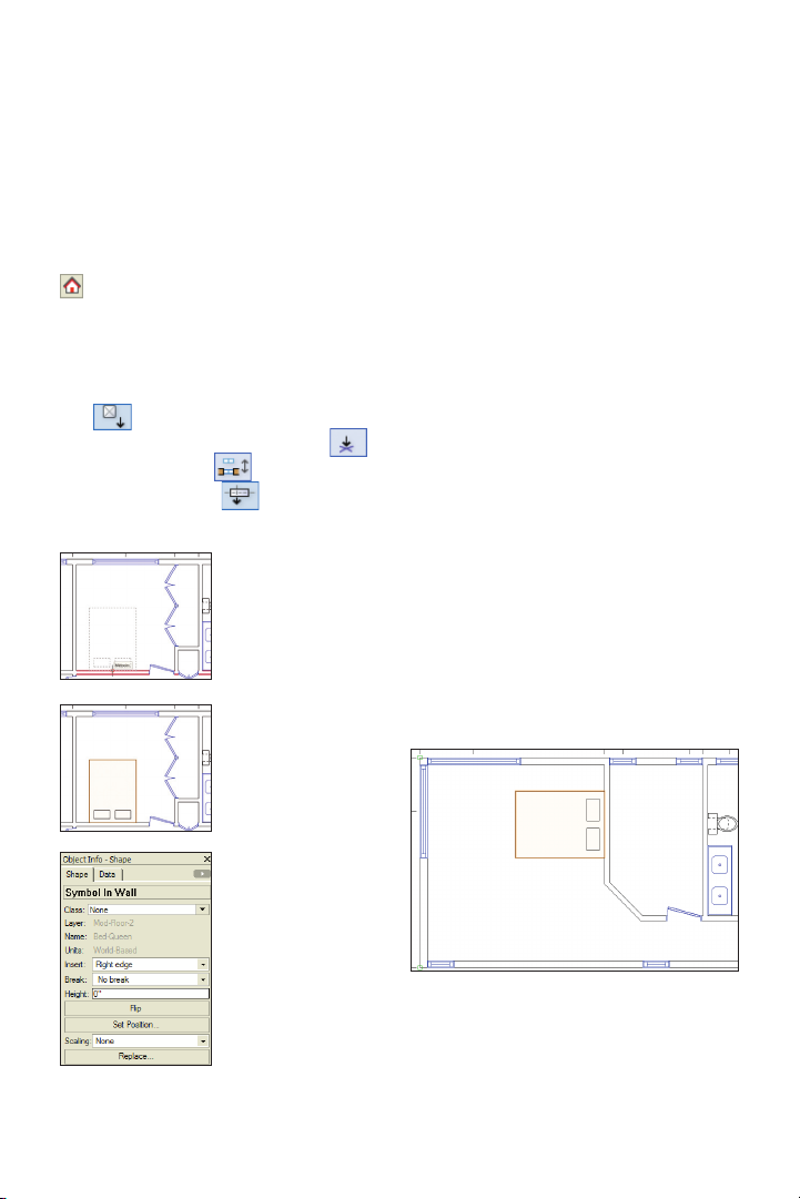
Next, you insert two instances of the BedQueen symbol in the floor plan.
3. In the Resource Browser, verify that your
file is active (if not, click the Home button
), and then scroll down and open the
Symbols/Plug-In Objects folder (if it’s not open
already). Scroll down the list, and then doubleclick the Bed-Queen symbol. In the Basic
tools palette, notice that the Symbol Inser-
tion tool is now active. In the Tool bar,
make sure Standard Insertion Mode ,
Wall Insertion Mode , and Align Actual
Insertion Point Mode are all active.
Click the hall bedroom wall’s midpoint once,
where shown at top.
Move your cursor
above and below
the wall (notice how
the symbol ips),
and then click above
the wall to place the
bed symbol in the
wall, as shown at
center. In the Object
Info palette, verify
that the symbol is
inserted in the wall
(see Notes below
figure), and examine
the available properties for a 2D symbol,
as shown at bottom.
Notes:
1) If the symbol is not inserted in the wall,
press the Delete key to remove it from the draw-
ing and try again.
2) You insert the symbol in the wall so that if
you move the wall, the bed symbol moves with it.
Tips:
1) Use symbols in the early design stages as
temporary placeholders for geometry that you
fully develop later in the design process. You can
incorporate changes by editing symbols or by
replacing symbol instances with other symbols.
2) You can optionally scale symbol instances
by specifying a symmetric factor or asymmetric
X’ and Y’ factors in the Scaling section of the
Object Info palette.
4. With the Bed-Queen symbol still active, insert another instance in the master
bedroom’s vertical wall (at the midpoint),
oriented as shown.
64 | Vectorworks Fundamentals 2011 Getting St arted G uide
Page 65

Inserting a Plug-In Object
Next, you insert a scale bar plug-in object
into the drawing.
5. From the Dims/Notes tool set,click the
Scale Bar tool . Double-click approxi-
mately where shown below to display the
Object Properties dialog
box. Properties dialog
box. Adjust settings (1/4”
[6.35mm], 1’0” [.305m],
10’0” [3.048m]) as shown
at the right, and then
click OK to create the
scale bar plug-in object
(shown above).
In the Object Info
palette, notice that
unlike the simple
Bed-Queen symbol,
the plug-in object has
parameters that let
you change the size
and configuration of
each instance, as
shown at right.
6. Save the file.
Vectorworks Fundamentals 2011 Getting St arted G uide | 65
Page 66

Page 67

Section 6:
Annotation Tools
In two exercises, this section covers the following key processes for adding text and
dimensions to your drawings:
• Creating Text (pg 68)
• Creating a Callout (pg 69)
• Setting Dimension Preferences (pg 71)
• Creating Constrained Linear Dimensions (pg 72)
• Creating an Angular Dimension (pg 73)
• Creating a Radial Dimension (pg 73)
In these exercises, you continue working with the sample architectural file from Exercise 12
(pg 63) as you create general notes in a sheet layer, and then you activate a design layer to
create a callout and floor plan dimensions.
Vectorworks Fundamentals 2011 Getting St arted G uide | 67
Page 68

Exercise 13: Creating Text
In this exercise, you create a text block on a sheet layer, and then you create a callout in a
design layer. The completed exercise is shown in the following figures.
box is displayed, and the Object Info palette
displays text controls. In the Object Info
palette, select 14 from the Size drop-down
list, and then select Left from the Horiz.
Align drop-down list. Click inside the text
editing box, and then enter the text shown
Creating text
You start the exercise by creating a couple
of standard notes in a text block.
1. Open the GS-VWFx13 -Step01.vwx file
in the Data Set folder. The file opens with
the first floor plan sheet layer active.
2. Zoom in on the upper left corner of the
drawing sheet. From the Basic tools palette,
click the Text tool . Click and drag the
cursor to dene the text width limit, approximately where shown below. A text editing
. Press the Esc key to close the text editing
box and create the standard notes [blank in
beta 4; but the text is still present if you click
inside the text box.]. Press the X key, and
then if necessary:
• Drag the text box by the text to
reposition it.
• Drag a corner reshape handle to
resize the text box and complete the text, as
shown at right.
68 | Vectorworks Fundamentals 2011 Getting St arted G uide
Note: To create a single line of text in your own
drawings, click the Text tool , and then
click to specify a start point. You can then either
start typing the text or adjust text settings in
the Object Info palette before you type the text.
Press the Esc key when finished.
Page 69

Creating a Callout
Next, you activate a saved view, and then
you create a callout in the Mod-Floor-2
design layer to identify exterior decking.
3. From the View
bar, select Floor
Plan-2 from the
Saved Views dropdown list (shown at
left) to activate it. In
the View bar, notice
that the Mod-Floor-2 design layer is now
active. Zoom in on the area shown below.
4. From the Basic tools palette, click the
Callout tool . In the Tool bar, enable
Towards target mode and Two-point
mode , and then click Callout Tool
Preferences . In the Callout Prefer-
ences dialog box, adjust settings as shown
(2.5” [63.50mm], 1/4” [6.35mm]), and then
click OK to save the settings.5.
Vectorworks Fundamentals 2011 Getting St arted G uide | 69
Page 70

Click two points in order—start outside the
deck above the dimensions, and then click
inside the deck for the second point—approximately where shown at the top. In the
Notes Manager: Callout dialog box, enter
the callout text (shown at left), and then click
OK to place the callout in the drawing,
similar to the one
shown at bottom.
6. Save the file.
70 | Vectorworks Fundamentals 2011 Getting St arted G uide
Page 71

Exercise 14: Creating Dimensions
In this exercise, you create a few different types of dimensions. The completed exercise is
shown in the following figure.
Dimension Notes:
1) Associative dimensions “attach” them-
selves to drawing objects by placing parametric
constraints on vertices of selected geometr y.
Parametric constraints let dimensions move
and update values when you move or resize
associated geometry or (for linear and chain
Setting Dimension
Preferences
You start the exercise by adjusting dimension creation and precision preferences.
1. Open the GS-VWFx14- Step01.vwx file
in the Data Set folder. The file opens with
the Mod-Floor-2 design layer active.
2. Right-click a blank area and select
Document Preferences. In the Document
Preferences dialog box, select the Dimensions tab. Adjust settings (8 Mils [.2032mm])
as shown, and then click OK.
dimensions only) modify associated geometry if
you change the Length parameter.
2) To turn off display of the parametric con-
straints, select Tools > Options > Vectorworks
Preferences from the menu, and then select the
Display tab and turn off the Show Parametric
Constraints option. Leave the display on for
these exercises.
3) If the Associative Dimensions option is
disabled, any dimensions you create will not be
attached to—or control—geometry you snap to.
4) Refer to the Online Help’s Associative
Dimensioning topic for more information.
5) In your own files, you can create or impor t
custom dimension standards and use them
individually, or to replace default standards (in
the active drawing only) if you need to adjust
any parameters such as Offset Text size. Refer
to the Online Help’s Using Custom Dimension
Standards topic for more information.
6) For your own drawings with dimensions
based on multiple standards, you can set the cur-
rent dimension standard from the Tool bar when
any dimension tool is active.
Vectorworks Fundamentals 2011 Getting St arted G uide | 71
Page 72

3. From the menu, select File > Document
Settings > Units. In the Units dialog box,
select the General Display and Dimensions
tab. Change the Angle Precision to 0 (zero),
and then verify or adjust other settings.
Select the Dual
Dimensions tab, and
then verify or adjust
settings as shown
at left. Click OK to
save the settings.
Creating Constrained Linear
Dimensions
Next, you use the Constrained Linear
Dimension tool to create orthogonal dimen-
sions in the floor plan.
4. From the Dims/Notes tool set, click the
Constrained Linear Dimension tool .
Snap to object vertices marked with green
squares (parametric constraints of associative dimensions) to create dimensions approximately where shown (highlighted - see
Notes below figure).
Notes:
1) The first two clicks determine dimension
points; the third click orients and places the
dimension.
2) Pick up points of existing dimension geom-
etry, and then use SmartCursor cues to align new
dimensions as you create them.
3) Press the X key, and then drag dimension
lines or text if you need to move either. You can
also select multiple dimension objects, and then
drag their dimensions lines together.
4) In your own drawings, you can dynamically
or precisely adjust witness line lengths for one
or more dimension objects. Refer to the Online
Help’s “Editing Dimensions with the Mouse” and
“Editing Dimension Properties” topics for more
information.
72 | Vectorworks Fundamentals 2011 Getting St arted G uide
Page 73

Creating an Angular
Dimension
Next, you create an angular dimension in
the floor plan.
Creating a Radial
Dimension
Next, you create a radial dimension in the
floor plan.
5. From the Dims/Notes tool set, click the
Angular Dimension tool . Click the in-
side wall edges (near
the arrow points),
and then click to
place the angular
dimension approximately where shown
at top. In the Object
Info palette, select
Horizontal from the
Text Rot drop-down
list. In the Attributes
palette, select Solid
from the Fill Style
drop-down list
(shown at center), to
complete the angular
dimension, as shown
at bottom.
Note: You change the Fill Style to Solid because
dimension fills are turned off (by the Dimension
class setting) in this file to properly display dual
dimensions.
6. From the Dims/Notes tool set, click the
Radial Dimension tool . In the Tool
bar, enable Interior Radial Dimension
Mode and Right-Hand Shoulder
Mode . Click the inside edge of the
curved wall, and then click to place the radial dimension approximately where shown.
7. Press the X key twice to clear the selection, and then save the file.
Vectorworks Fundamentals 2011 Getting St arted G uide | 73
Page 74

Page 75

Section 7:
Drawing Presentation
In three exercises, this section covers the following processes for printing drawings set up
with viewports on sheet layers:
• Duplicating a Sheet Layer (pg 76)
• Adjusting Page Setup Settings (pg 77)
• Cleaning Up the New Drawing Sheet (pg 77)
• Creating a Viewport (pg 78)
• Cropping a Viewport (pg 79)
• Setting Up the Printer (pg 81)
• Printing to a File (pg 82)
In these exercises, you duplicate a sheet layer and then create a floor plan viewport (that
displays objects on multiple design layers) on the new sheet layer. You then crop the viewport to hide extraneous objects. You complete the tutorial by setting up your printer and then
printing the floor plan drawing to a file. After completing the exercises in the section, your
drawing should look similar to the following figure.
Vectorworks Fundamentals 2011 Getting St arted G uide | 75
Page 76
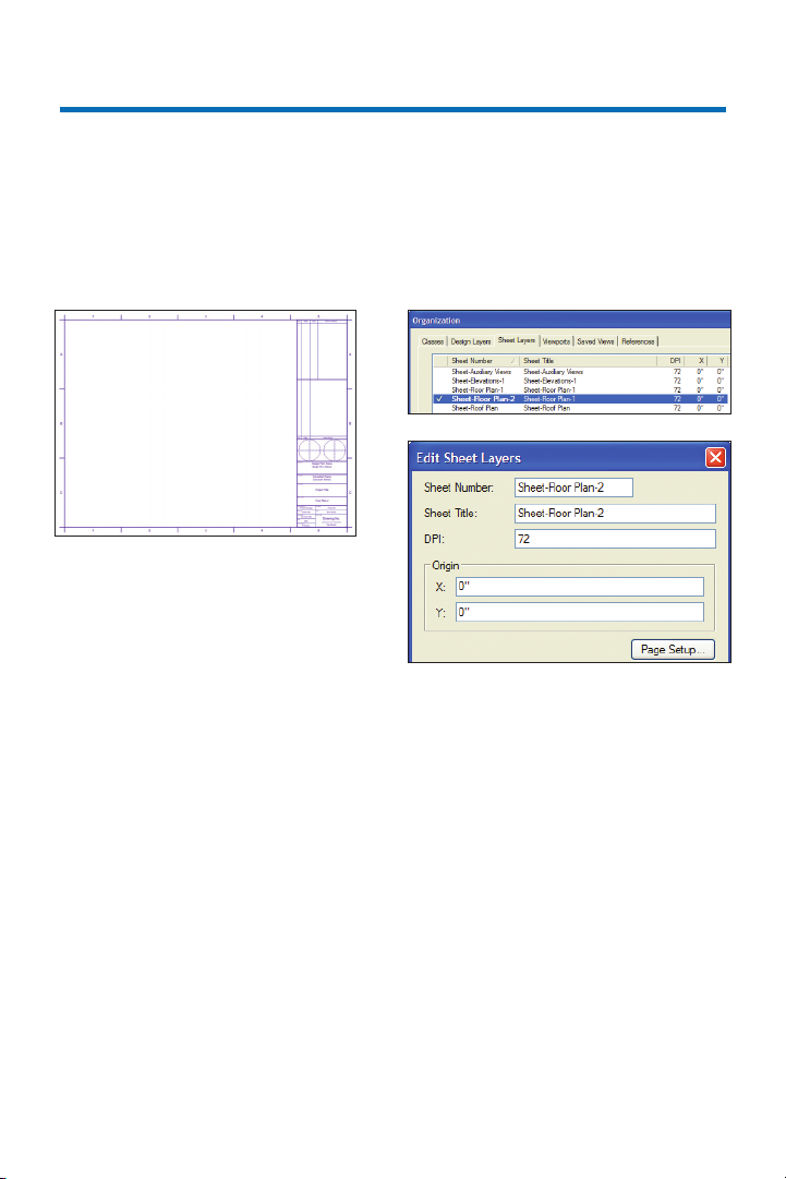
Exercise 15: Working with
Sheet Layers
In this exercise, you duplicate an existing sheet layer and then modify its display properties
and page setup settings. The completed exercise is shown in the following figure.
Duplicating a Sheet Layer
You start the exercise by duplicating an
existing sheet layer.
1. Open the GS-VWFx15- Step01.vwx file
in the Data Set folder. The file opens with
the first floor plan sheet layer active.
2. Press Ctrl+Shift+O for the Organization
dialog box shortcut. Select the Sheet Layers
tab, and then right-click the Sheet-Floor
Plan-1 sheet layer and select Duplicate
from the context menu. Notice the sheet
number for the new sheet layer was
automatically incremented, as shown at top
Right-click the Sheet-Floor Plan-2 sheet
layer and select Edit from the context menu.
In the Edit Sheet Layers dialog box, change
the Sheet Title to Sheet-Floor Plan-2, as
shown next. Keep the Edit Sheet Layers
dialog box open for the next step.
Notes:
1) In your own drawings, click New if you don’t
have any existing sheet layers in the file.
2) You can also optionally create a new sheet
layer when you create a viewpor t. In this tutorial,
you create a viewport in Exercise 16 (pg 78).
76 | Vectorworks Fundamentals 2011 Getting St arted G uide
Page 77

Adjusting Page Setup
Settings
Next, you change page setup properties for
the new sheet layer.
3. Click Page Setup, and adjust settings in
the Page Setup dialog box, as shown. Click
OK three times to save the settings and
close all open dialog boxes.
Note: Your Horizontal and Vertical values
in the Pages section may vary.
Cleaning up the New
Drawing Sheet
4. In the View bar, notice that the SheetFloor Plan-2 sheet layer is now active. Press
the X key, and then hold down the Delete
key and click the general notes (text object)
and viewport. Release the Delete key to
remove both objects from the sheet.
5. Select the drawing border, and then
scroll down in the
Object Info palette
and click Edit Title
Block. In the Edit
Title Block dialog box, select the Sheet tab,
and then change the Sheet Title, as shown
at right. Click OK to save the change, and
then press the X key twice to clear the selection, and examine the new (empty) drawing
sheet, as shown below.
6. Save the file.
Vectorworks Fundamentals 2011 Getting St arted G uide | 77
Page 78

Exercise 16:
Working with Viewports
In this exercise, you create and crop a viewport. The completed exercise is shown in the
following figure.
• Verify other
settings (shown
at left).
• Click Layers.
In the Viewport
Layer Properties
dialog box, adjust
visibilities as shown
below and then click
OK.
Creating a Viewport
You start the exercise by creating a viewport on the new sheet layer from Exercise
15 (pg 76).
• Click OK to
1. Open the GS-VWFx15.vwx file in the
Data Set folder. The file opens with the
(blank) second floor plan sheet layer active.
2. From the menu, select View > Create
Viewport. In the Create Viewport dialog
box:
• Change the Viewport Name to VP-
Floor Plan-2.
• Change the Drawing Title to Floor
Plan 2.
• Select 3/16”=1’0” from the Scale
drop-down list.
create the viewport.
Drag the viewport
into the approximate
center of the drawing
border, as shown below.
78 | Vectorworks Fundamentals 2011 Getting St arted G uide
Page 79

Cropping a Viewport
1
2
3
5
6 6 7
8
Next, you crop the viewport to create a
curved break line for the deck.
3. Press Ctrl+6 to zoom in on the selected
viewport. Double-click any object in the
viewport to activate editing mode. In the Edit
Viewport dialog box, select the Crop option,
as shown below at left, and then click OK to
enter Viewport Crop mode. Press 5 for the
Polyline tool shortcut, and then enable
Tangent Arc Mode in the Tool bar.
Start by snapping to the outside wall line,
approximately where point 1 is shown. Continue clicking approximately where points 2
and 3 are shown, and then snap to the outside wall line approximately where point 4 is
shown (do not terminate the polyline yet) to
create the curved section of the polyline. For
the next vertex, enable Corner Vertex Mode
in the tool bar, and click approximately
where point 5 is shown. Continue clicking
points 6 through 7, and then double-click
point 8 to terminate the polyline and crop the
viewport. In the Object Info palette, enable
the Closed option to complete the polyline
(see Note below), as shown at bottom.
Leave the polyline selected for the next
step.
Note: A polyline does not have to be closed
to crop a viewport; the Close option is shown
here to demonstrate the proper technique for
creating continuous-line crop objects.
4
Vectorworks Fundamentals 2011 Getting St arted G uide | 79
Page 80

Next, you use the 2D Reshape tool to hide
the straight edges of the crop polyline.
4. Press the – key for the 2D Reshape tool
shortcut. In the tool bar, activate Hide or
Show Edges Mode , and then click the
midpoint reshape handle for each of the poly-
line’s ve straight segments to hide them so
that only the curved portion is now visible, as
shown at top. Click Exit Viewport Crop to return to the sheet layer, and then press the X
key twice to clear the selection. Press Ctrl+6
to adjust the display. Examine the completed
viewport crop, as shown at bottom.
5. Save the file.
80 | Vectorworks Fundamentals 2011 Getting St arted G uide
Page 81

Exercise 17: Printing the Drawing
In this exercise, you set up your printer and then print the sheet layer with the cropped
viewport from Exercise 16 (pg 78).
Note: To save paper, you practice using print commands by printing to a file.
Setting Up the Printer
You start the exercise by setting your
printer’s properties.
1. Open the GS-VWFx16.vwx file in the
Data Set folder. The file opens with the
second floor plan sheet layer active.
2. From the menu, select File > Page
Setup. In the Page Setup dialog box, click
Printer Setup. In the Printer Setup dialog
box, select the name of the desired printer
(see Notes below figure), and then choose
a paper size— or specify dimensions for a
custom size—to match the 24” x 18” US
Arch C size that you specified in the “Adjusting page setup settings” section in Exercise
15 (pg 75). Your printer setup dialog box
might look similar to the following figure:
Notes:
1) The printer selection above is for illustration
purposes only. Due to the extensive variety
of printers available, it’s impossible to provide
explicit instructions and illustrations of settings
for your particular printer. For best results, select
a printer that you’re familiar with.
2) For some printers, you may have to adjust
page size and/or scaling for proper operation.
3. Click OK twice to save the settings and
close both dialog boxes.
Vectorworks Fundamentals 2011 Getting St arted G uide | 81
Page 82

Printing to a File
Next, you print the active sheet layer to
a file.
4. From the menu, select File > Print. In
the Print dialog box, enable the Print to
File option, and then enable the Pages
from: 1 to: 1 option. Your Print dialog box
might look similar to the following figure.
Click OK, and then specify a file name and
location in the Print to File dialog box. Click
Save to print the drawing to the location
you specified.
5. Save the file. Congratulations! You have
now completed the tutorial!
82 | Vectorworks Fundamentals 2011 Getting St arted G uide
Page 83

 Loading...