

Page 1

2011 Getting Started Guide
The contents of this printed guide and
accompanying exercise CD were originally
created for Nemetschek Vectorworks, Inc.
by Steve Hader.
Page 2

©1985–2010 Nemetschek Vectorworks, Inc.
Vectorworks and MiniCAD are registered trademarks of Nemetschek Vectorworks, Inc.
Renderworks is a trademark of Nemetschek Vectorworks, Inc.
Windows is a registered trademark of the Microsoft Corporation in the United States and other countries.
Macintosh is a registered trademark of Apple Inc.
Page 3

Table of Contents
Introduction ........................................................................................................................ 3
Section 1: Program Installation and Setup
Installing the Vectorworks Architect Program
Exercise 1: Launching the Program and Opening the Starting File
Exercise 2: Adjusting Preference Settings
Section 2: Laying Out Room Areas
Exercise 3: Drawing Exterior Walls
Exercise 4: Drawing Interior Walls
Exercise 5: Drawing Second-Floor Walls and Adding a Stair
Section 3: Creating Architectural Elements
Exercise 6: Creating the First-Floor Plan
Exercise 7: Creating the Second-Floor Plan
Section 4: Working with Multiple Level
Exercise 8: Creating and Modifying the Roof
Exercise 9: Editing Architectural Elements
Section 5: Creating Construction Documents
Exercise 10: Generating Construction Drawings.
Exercise 11: Adding Annotations
Exercise 12: Printing Construction Drawings.
............................................................................ 9
.............................................................. 9
................................................................. 12
..................................................................................... 15
............................................................................ 16
.............................................................................25
......................................................................... 37
...................................................................38
..............................................................48
................................................................................55
.............................................................56
................................................................61
.....................................................................69
...................................................... 70
................................................................................ 81
............................................................84
........................... 10
....................................29
Page 4

Page 5
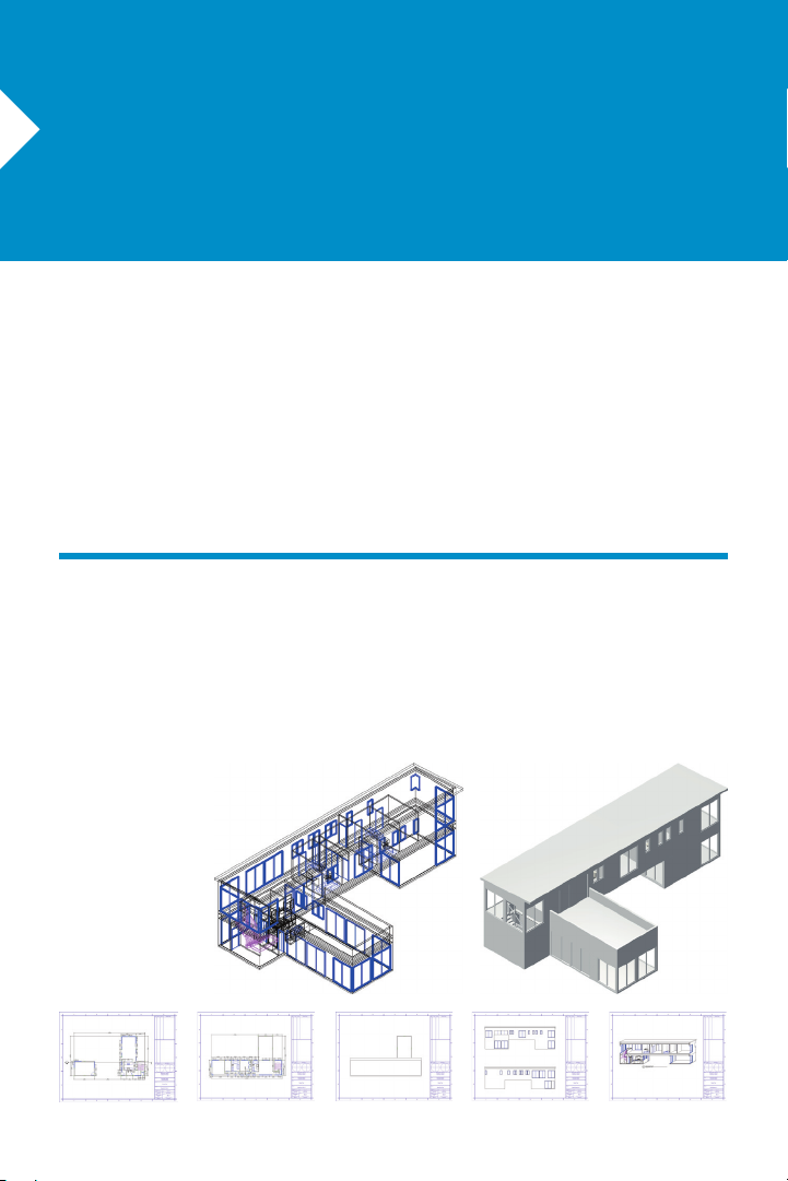
Introduction
Welcome to Vectorworks Architect! This tutorial will introduce you to key tools and techniques
for drawing and editing as well as provide a streamlined workflow to provide the proper
framework for exploring the full power of Vectorworks Architect on your own.
Important: For free tutorial updates, bonus content, and instructional videos from the
Architect Getting Started website, see www.nemetschek.net/training/2011/architect-
2011-getting-started-guide.php.
Overview of the Modeling Process
In this thematic tutorial, you use Vectorworks Architect to design a modern vacation home.
You begin with a pre-configured (but otherwise blank) starting file, and continue using this
single file for all design phases and documents. You complete the project by creating and
printing various construction documents:
Note: The house
design in this tutorial
was adapted from
the award-winning
Dwell Home design
by Resolution: 4
Architecture.
Vectorworks Architect 2011 Getting St arted Guide | 3
Page 6

As you work through 11 continuing
exercises, you develop the house design
using a combination of standard Vectorworks and Vectorworks Architect tools to
complete the following design features and
documentation processes in order:
• Room layouts (walls)
• Architectural elements (floors, doors,
windows, and other symbols)
• Multiple level features (roof)
• Construction documents (commonly used)
• Annotations
• Batch Printing
Notes:
1) Starting with Exercise 3 (p. 16), you can
optionally open completed exercise files (from the
DVD’s Data Set folder or www.nemetschek.net/
training/2011/architect-2011-getting-started-
guide.php) to check your model or to skip ahead
to the beginning of the next exercise. For
example, open the GS -V WA x10.vwx file
(completed Exercise 10) to start at the beginning
of Exercise 11. See General Exercise Tips (p.
6) for more information.
2) This tutorial focuses on creating or setting
up only the most common construction
documents for a house design project.
4 | Vectorworks Architect 2011 Getting St arted Guide
Page 7
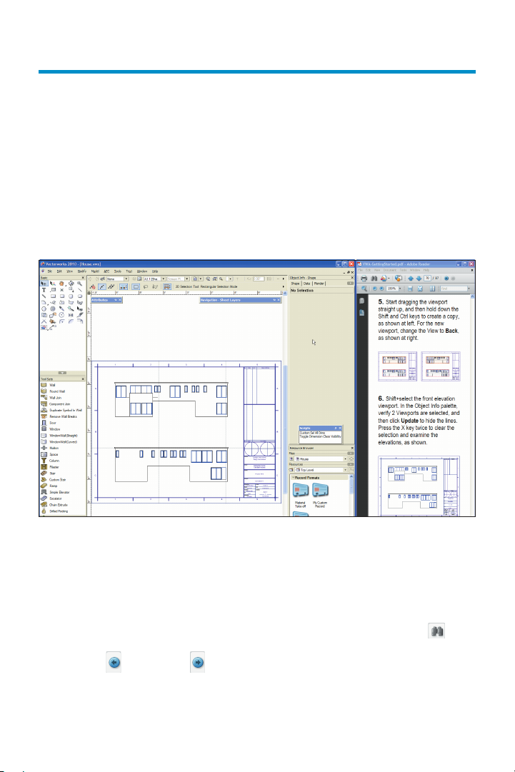
How to Use This Tutorial
This tutorial is also provided as an e-Book in PDF format. You can view the PDF tutorial
on-screen for enhanced electronic benefits including navigation links and search features.
If you choose to view the tutorial on-screen, you can optionally enable Reflow viewing mode
(available from the View menu only in the Adobe Reader 7 or Adobe Acrobat 7 programs,
available from the View > Zoom menu in newer versions) to display the text with a wrapping
effect similar to a web browser. You can then adjust the Zoom level and resize both the
tutorial and Vectorworks windows to display them side-by-side as on p. 6.
Notes:
1) You can review workflow sequencing and
locate specific procedures by scanning the
process lists at the start of each section. The
process lists are also hyperlinked to facilitate
navigation.
2) If you view the tutorial on-screen, look for the
Previous View and Next View tools at
the bottom of the screen (or available in the Page
Navigation tool bar in newer versions). These useful
tools—available in Adobe Reader and Acrobat—let
you revert or repeat navigational changes by page
controls, bookmarks, and hyperlinks.
3) The Adobe Reader Search tool
provides more extensive options for searching
text than the Find command.
Vectorworks Architect 2011 Getting St arted Guide | 5
Page 8

General Exercise Tips
Use the following tips to facilitate working with your exercise drawing files:
• Read each step carefully and make sure
your results match the figures. If your results
vary from the figures, stop immediately and
review the previous steps. If you can’t find
the problem quickly, start the exercise over
with the appropriate supplied file.
• Alternate methods are shown for acti-
vating many tools, commands, and modes.
Use the method that works best for you.
• In many cases, you must click in the
drawing area after using the Navigation
palette before continuing with the next step.
• Watch for SmartCursor cues that appear
when you hover your cursor over significant
drawing object geometry. Pause briefly over
snap points to display the red snap box, and
watch for the red confirmation dot displayed
temporarily after you complete the snap.
When too many red snap boxes are
displayed in congested areas, you can press
the Esc key once to clear the display, or you
can temporarily disable all snaps by holding
down the backquote key (`).
• For some operations, additional view
adjustments may be required. For these
cases, press the Z key for the Snap Loupe
shortcut, or use the Zoom, Pan, and Fit to
Objects tools as required. If you have a
mouse wheel, use it to zoom in and out.
• To pan across the drawing at any time
(even if a tool or command is active), hold
down the Space bar and drag the cursor.
• If you inadvertently cleared a selection
required for an active tool or command,
press Space bar + X temporarily, and then
select the object(s).
• Many tools have different operational
modes, which you can select in the Tool bar
(located above the drawing window).
• Keep the Object Info palette open. To
open it, select Window > Palettes > Object
Info. It displays valuable information and
provides access to key properties of
selected objects.
• Press the Esc key to cancel any
operation. If you are using a tool, it will still
be active, but you can then start drawing
again or choose another tool. Sometimes,
you must press the Esc key before you use a
keyboard shortcut to activate another tool.
• Use the Undo command in the Edit
menu to revert steps as necessary (both
drawing and view changes are reverted).
6 | Vectorworks Architect 2011 Getting St arted Guide
Page 9
• For tools that create multiple segments
(such as the Wall tool), press the Delete key
once while the tool is active to revert a single
segment, or press it repeatedly to revert
additional segments.
• If multiple files are open, you may need
to click the Resource Browser’s Home
button
if your house file isn’t active.
• Object artifacts may remain in the
drawing area after some drawing and editing
operations. To refresh the screen and clear
the artifacts, double-click the Pan tool
(in the Basic tools palette).
• Save your files often to prevent data loss.
Important:
1) Exercise steps in this tutorial are based on
default preference settings from a new
installation of the Vectorworks Architect
program. Results for some steps may vary
from the figures if your preference settings
differ from the defaults.
2) Close any open files before you open a
completed exercise file (only if you plan on
using it to start the next exercise).
Using Metric Units with
Exercises
All exercise data set files for this tutorial are
set to use imperial units. If you want to use
metric values for the exercise steps, enter
the values exactly as shown in [square
brackets, with the unit mark], and Vectorworks will convert the values accordingly. If
you want to measure distances or drawing
objects for reference, use the appropriate
dimension tool and object snaps to create
temporary dimensions, which are set by
default to display alternate units in metric
values. Delete the temporary dimensions
when finished.
Note: For proper exercise operation—and to
validate your results with the imperial figures—do
not change the document’s units setting to metric.
Vectorworks Architect 2011 Getting St arted Guide | 7
Page 10

Checking Your Work
The GS -V WAxCheck.vw x file is included
in the Data Set folder so you can verify the
accuracy of your file. If you want to use this
file to check your work:
1. Copy the Data Set folder on the DVD
to any location on your hard disk.
2. In step 3 of Exercise 1 (p. 10), open
the GS-V WAx01.vwx file in the Data Set
folder, and then save the file under the
name House.v wx in the Data Set folder
on your hard disk.
Notes:
1) Before you use any of the supplied files to
start any other exercise, save your current file
under a different name, and then open the
read-only file (from the Data Set folder on your
hard disk) and save it as House.vwx in the Data
Set folder.
2) You must name your file “House“ and
save it in the Data Set folder to ensure the
GS-VWAxCh eck.v wx file works properly.
3. After saving your House.vwx file at the
end of exercises 3 through 11, open the
GS-V WA xCheck.v wx file from the Data
Set folder on your hard disk, and then
follow the exercise-specific checking
instructions exactly as shown in the last
steps of the exercise.
Keyboard Shortcuts
All keyboard shortcuts included in this
guide are based on the Windows operating
system. If you’re using a Macintosh, use the
Option key instead of the Alt key, and use
the Cmd key instead of the Ctrl key. Refer
to the Vectorworks 2011 Shortcuts PDF
file (available from the Online Help) to print
a complete list of your own keyboard
shortcuts.
8 | Vectorworks Architect 2011 Getting St arted Guide
Page 11

Section 1: Program
Installation and Setup
In this section, you start by installing the Vectorworks Architect program. Following installation, two exercises cover the following program setup and interface adjustment processes:
• Activating the Architect Workspace (p. 10)
•
Opening the Starting File (p. 11)
• Adjusting Vectorworks Preferences (p. 12)
• Adjusting Snapping Settings (p. 13)
• Adjusting Grid and Smart Point Settings (p. 13)
• Setting the Default Font (p. 14)
• Adjusting the Navigation Palette Display (p. 14)
• Adjusting Quick Prefs (p. 14)
In these exercises, you activate (or reset) the Vectorworks Architect interface, and then you
adjust program preference settings and adjust the interface.
Installing the Vectorworks
Architect Program
Note: If you have already installed Vectorworks Architect, start with step 2 below.
1. Follow the installation instructions in the
ReadMe le located in the root folder of your
installation DVD.
2. Start the program. You can do this by
selecting Programs > Vectorworks2011 >
Vectorworks2011 from the Windows
Start menu.
3. From the menu, select Help > Check for
Updates. If updating is necessary, follow
the on-screen instructions.
4. Close Vectorworks (if it’s still running) to
reset the program.
Vectorworks Architect 2011 Getting St arted Guide | 9
Page 12
Exercise 1: Launching the Program
and Opening the Starting File
In this exercise, you launch the application and activate the Vectorworks Architect
workspace. After a brief orientation of the Architect interface, you then open the supplied
starting le.
Activating the Architect
Workspace
You start by launching the Vectorworks
program.
1. From the Windows Start menu, select
Programs > Vectorworks2011 >
Vectorworks2011.
10 | Vectorworks Architect 2011 Getting St arted Guide
2. From the menu, select Tools >
Workspaces > Architect. If the Architect
workspace is already active, select it again
to reset the interface. Position the
Navigation palette where shown, and
examine key areas of the interface identied
in the following gure.
Page 13

Opening the Starting File
Next, you open the supplied starting le. To
save time, this starting le contains many
pre-congured resources, and is already
fully set up for creating a two-story structure
without a basement.
Note: Before you open the supplied starting file,
see Checking Your Work (p. 8).
3. From the menu, select File > Open. In
the Open Vectorworks Drawing dialog box,
open the Data Set folder and open the
(read-only) GS-VWAx01.vwx
boundary is displayed, and it’s ready for
laying out the rst oor room areas.
4. From the menu, select File > Save
As
, and save the le under the name
House.vwx.
You can now skip ahead to Exercise 2 (p.
12), or you can use the Online Help
system to review the following commands
that were used to set up this le:
• Document Setup – Species layer
scale, drawing area (page setup), sheet
border, and title block settings used by the
Create Standards Viewports command.
• Model Setup – Creates basic design
layers, with appropriate height settings for
3D objects.
• Create Standard Viewports – Cre-
ates design layer, sheet layer, sheet layer
viewport, and class schemes appropriate for
selected construction documents. Also
creates matching “working” views, which
you use throughout the project to facilitate
le navigation.
le. The page
• Standard Naming – For enabling the
Auto-classing option to assign class names
and attributes to many of the objects you
create. Visibility of these classes is handled
automatically in sheet layer viewports and
saved views generated by the Create
Standard Viewports command.
Notes:
1) Design layers are used in architectural
projects as spatial containers for creating
drawing objects.
2) Sheet layers provide a 2D-only page layout
environment for printing.
3) Sheet layer viewports are individual 2D “live
camera view” objects that reside on sheet layers
but display 2D and 3D drawing objects on design
layers. When you modify drawing objects on a
design layer, the viewport itself doesn’t change,
but it displays the changes in the design layers.
4) Classes are used to control display
properties of drawing objects.
Important: As you start the tutorial, do not
be concerned if you don’t fully understand the
file structure and setup commands. As you
progress through the exercises, you will see
how the file structure works in context of a
design project. For step by step file setup
instructions from the Architect Getting Started
website, see www.nemetschek.net/
training/2011/architect-2011-getting-startedguide.php.
Vectorworks Architect 2011 Getting St arted Guide | 11
Page 14
Exercise 2: Adjusting
Preference Settings
In this exercise, you verify and adjust program preferences.
Adjusting Vectorworks
Preferences
Next, you verify or adjust key application
preference settings to ensure proper
exercise operation, turn on scroll bars to
facilitate navigation, and increase the
maximum number of undos so you can
revert exercise steps if necessary.
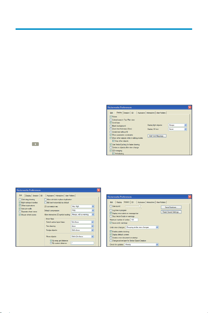
1. Click
bar and select Vectorworks Preferences.
In the Vectorworks Preferences dialog box,
select the Edit tab, and then verify or adjust
settings as shown (keep the dialog box
open for the next three steps).
on the far right side of the Tool
2. Select the Display tab, and enable the
Scroll bars option, and then verify or adjust
other settings as shown.
3. Select the Session tab, and then enter
100 in the Maximum number of undos
eld. Verify or adjust other settings as shown.
12 | Vectorworks Architect 2011 Getting St arted Guide
Page 15
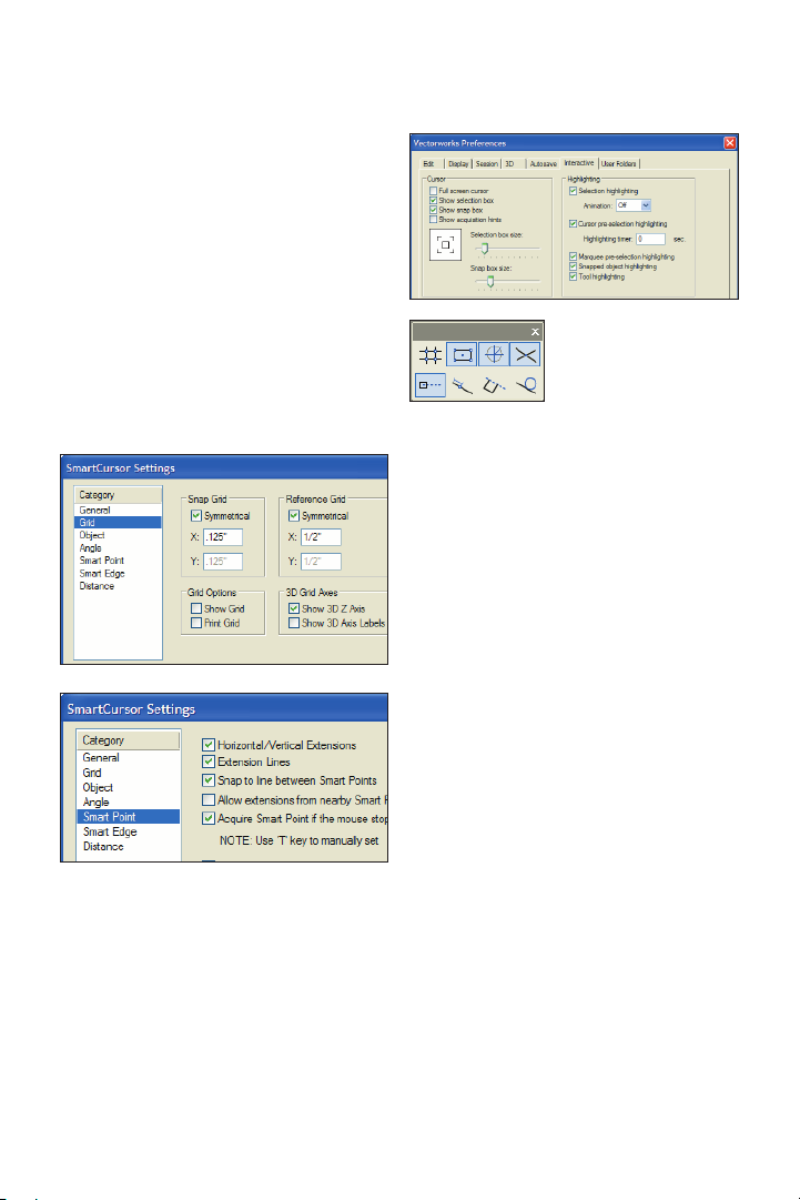
4. Select the Interactive tab, and then
change the cursor’s Selection box size and
Snap box size, and verify or adjust other
settings as shown at right. Click OK to save
the settings and close the dialog box.
Adjusting Snapping Settings
5. Verify or adjust options in the Snapping
palette (as shown at right), and then click
the X in the palette’s upper right corner to
close it.
Adjusting Grid and Smart
Point Settings
6. Press Ctrl + 8 to display the SmartCursor Settings dialog box. If a tip is displayed,
click OK and then select Grid from the
Category list. Clear the Show Grid Lines
and Print Grid Lines checkboxes, and
verify or adjust other settings (.125”
[3.18mm], 1/2" [12.70mm]) as shown at left.
From the Category list, click Smart Point,
and verify or adjust settings as shown at
right. Click OK to close the dialog box and
save the changes.
Vectorworks Architect 2011 Getting St arted Guide | 13
Page 16
Setting the Default Font
Next, you adjust the default font.
7. From the menu, select Text > Font >
Arial to set the default font (if it’s not set to
Arial already), and then select Text > Size >
12 to set the default font size to 12 point (if
it’s not set to 12 already).
Adjusting the Navigation
Palette Display
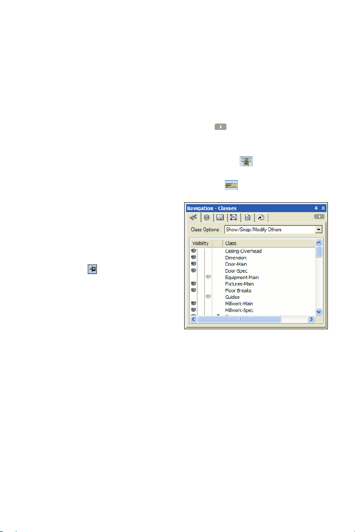
8. If your Navigation palette is not already
displayed, from the menu, select Window >
Palettes > Navigation. If necessary,
expand the Navigation palette by dragging
the lower right corner to resize it.
9. In the Attributes and Navigation palettes,
turn on Auto Hide
(Windows only).
Adjusting Quick Prefs
Next, you display appropriate Quick Prefs
on the Tool bar for instant access at all
times when any le is open.
10. Click on the far right side of the Tool
bar, and then from the Quick Prefs menu:
• Select Auto Join Walls to display the
Auto Join Walls
• Select Hide Details to display the
Hide Details
button on the Tool bar.
button on the Tool bar.
Page 17

Section 2: Laying Out
Room Areas
In three exercises, this section covers the following processes in the home design project:
• Drawing Connected Walls (p. 16)
• Applying Geometric Constraints to Walls (p. 18)
• Adjusting Dimension Preferences (p. 19)
• Dimensioning Walls (p. 20)
• Dynamically Adjusting the Layout (p. 20)
• Precisely Adjusting the Layout (p. 21)
• Drawing the Functional Area Walls (p. 25)
• Drawing the Pantry Wall (p. 26)
• Completing a Wall Y-Join with a Geometric Constraint (p. 26)
• Dimensioning Walls (p. 27)
•
Copying Walls for the Second Floor Plan (p. 29)
• Joining Walls (p. 30)
• Drawing Remaining Walls (p. 31)
• Dimensioning Walls (p. 31)
• Inserting a Stair Object (p. 32)
• Modifying the Stairwell, Foyer, and Deck Walls (p. 33)
In these exercises, you work on design
layers as you start the design by drawing
wall objects (using unique wall styles for
maximum exibility) in approximate
proportions. You then:
• Place geometric constraints on
related walls.
• Automatically create associative
dimensions for all walls.
• Use a combination of dynamic and
precise methods to progressively tighten the
accuracy and dene basic spatial relationships of the rooms.
Note: Although you can also use space planning
tools and massing models, this tutorial covers
tools for drawing walls directly.
Vectorworks Architect 2011 Getting St arted Guide | 15
Page 18
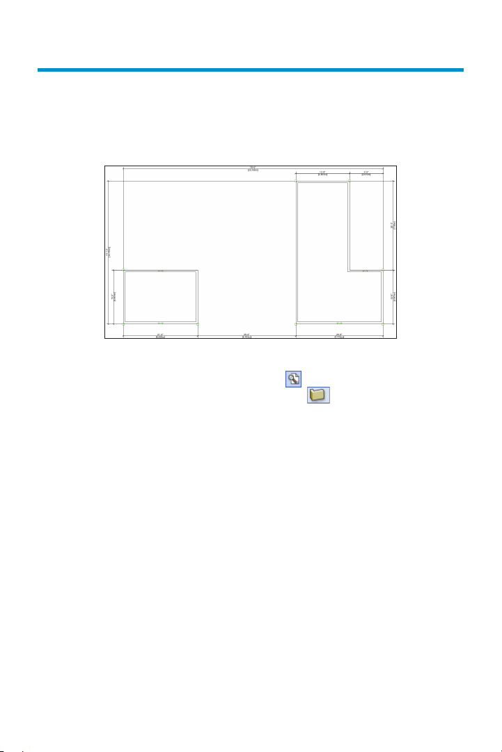
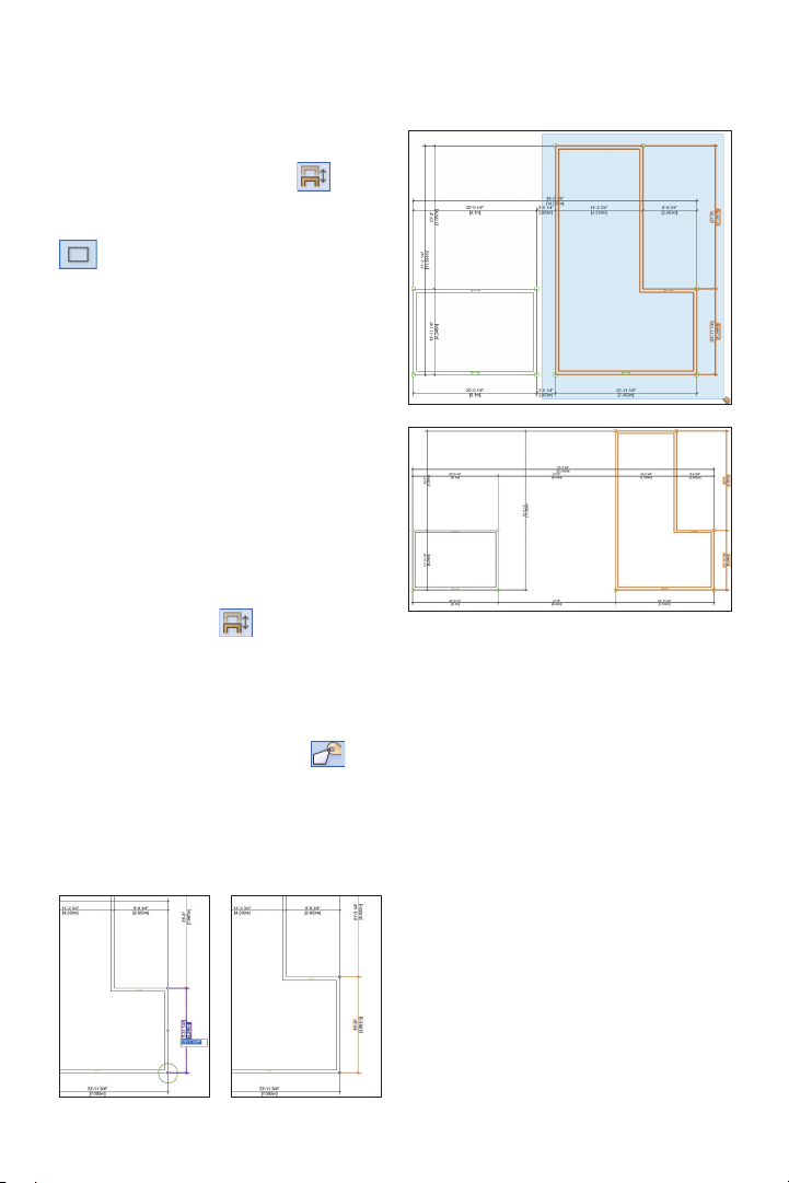
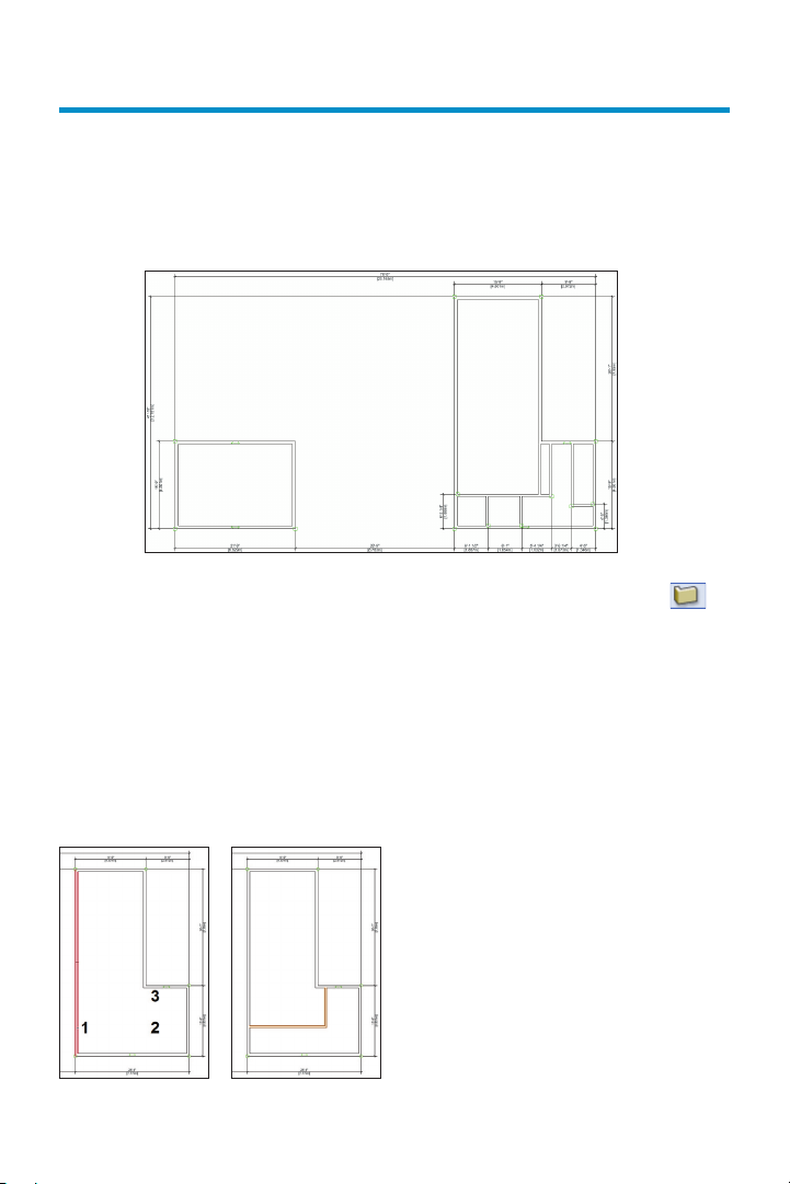
Exercise 3: Drawing Exterior Walls
In this exercise, you draw the exterior walls to dene the rst oor envelope. The completed
exercise is shown in the following gure.
Drawing Connected Walls
You start the exercise by setting an
appropriate zoom level, and then you draw
four walls using the 6.5" [165.1mm] Generic
Ext style to represent the storage room. You
use this wall style as a unique placeholder
for exterior walls until you replace it with the
nal conguration in Exercise 9 (p. 60). To
create this wall style, a default content wall
style was duplicated and renamed (the
original style was not modied) to avoid:
• Conicts for other users who may
already be familiar with the properties of the
default content style.
• Unintentionally replacing other walls in
a project that may have the default content
style property.
1. If you did not complete Exercise 2—or
you are unsure of your le’s accuracy—
open the GS-VWAx02.v w x le.
16 | Vectorworks Architect 2011 Getting St arted Guide
2. From the View bar, click Fit to Page
Area
click Wall
[165.1mm] Generic Ext from the Wall Style
drop-down list (if it’s not already active).
Note: Before you continue, view the animation of
steps 3 through 9 (AGSx03_03-09.mov file from
the DVD’s Movies folder or www.nemetschek.
net/training/2011/architect-2011-getting-started-
guide.php).
3. Draw four connected walls in clockwise
order, starting at the lower left corner,
approximately where shown at left (use the
page border for approximate positional
reference): Draw the rst two segments, and
then use angle snaps and acquire a Smart
Point (see Note 2 on p. 17) at the starting
vertex to control the length of the third
segment to keep the walls square.
. From the Building/Shell tool set,
. In the Tool bar, select 6.5"
Page 19
Notes:
1) Drawing exterior connected walls in a
clockwise direction ensures that the interior and
exterior sides are oriented correctly.
2) Before you draw the last segment, pause the
cursor briefly over the starting vertex until the
Smart Point is acquired (red box displayed). Pause
the cursor one time to acquire a Smart Point; pause
the cursor a second time to clear a smart point.
4. From the Basic tools palette, cclick the
Selection Tool
. In the Tool bar, make
sure the Enable Connected Walls Mode
option is enabled. Drag two of the walls
to verify the connections, as shown at right.
Next, you draw the L-shaped exterior walls
that dene the perimeter of the functional
area and living room.
5. Press the 9 key for the Wall tool shortcut.
Use the same drawing technique to draw six
connected walls in clockwise order, starting
at the lower left, approximately where shown.
6. Press the X key for the Selection Tool
shortcut. Drag various walls from the
L-shaped room to verify the connections,
as shown.
Vectorworks Architect 2011 Getting St arted Guide | 17
Page 20
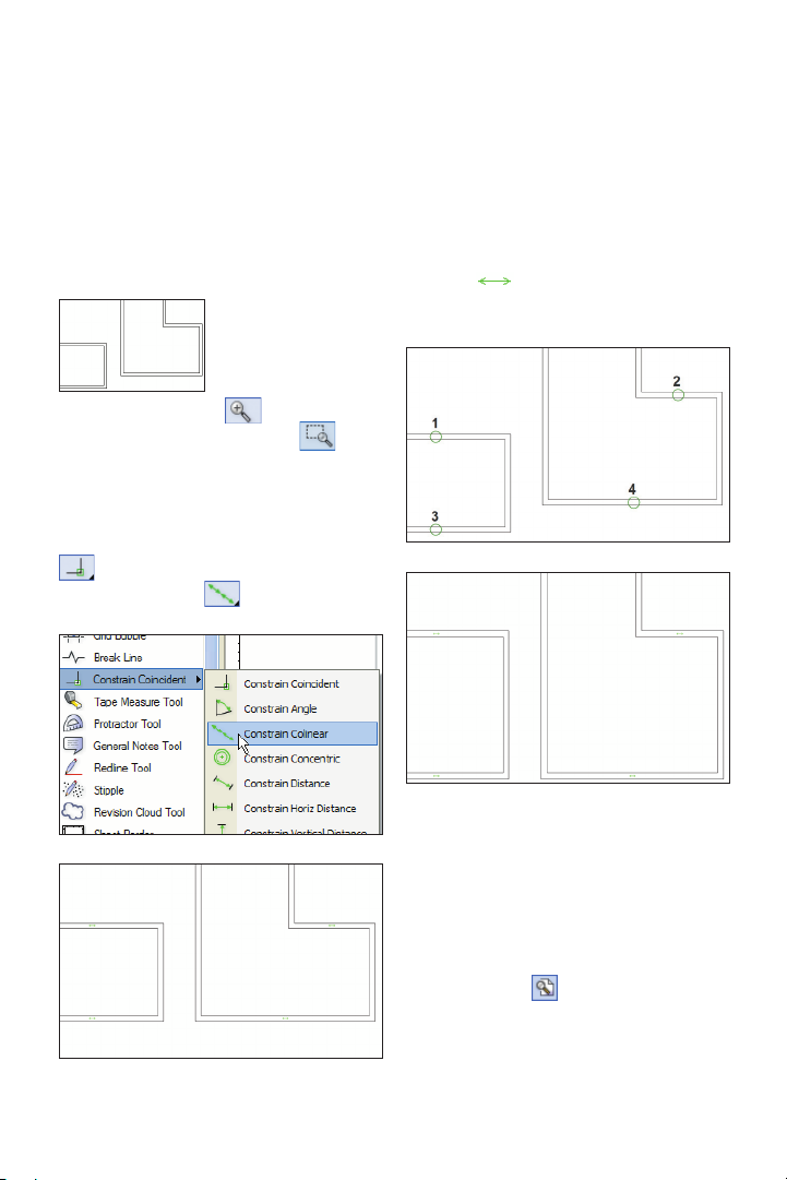
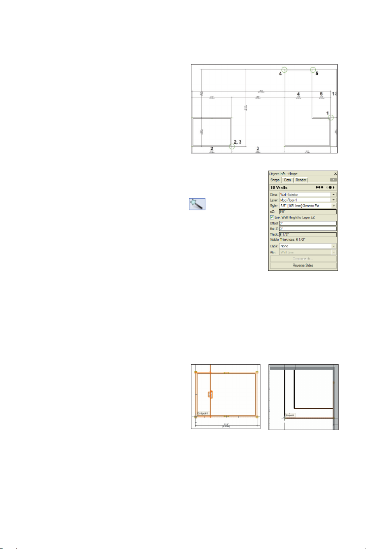
Applying Geometric
Constraints to Walls
Next, you apply colinear constraints to four
walls to maintain the distance between them
and their alignment.
7. Press the X key
twice to clear the
current selection.
click the Zoom tool
. In the Tool bar,
make sure Marquee Zoom Mode is
active, and then draw a marquee around the
area shown (at left) to zoom in. From the
Dims/Notes tool set, hold down the left mouse
button on the Constrain Coincident tool
to open the yout palette, and then click
Constrain Colinear , as shown below.
8. Click the midpoints of the wall segments
in order, (shown below) to place colinear
constraints between the midpoints and
constrain the walls along their centerlines
(notice the horizontal colinear constraint
indicators
either constraint fails, zoom in and try again.
), shown in the next gure. If
18 | Vectorworks Architect 2011 Getting St arted Guide
9. Press the X key and then drag one of the
upper and one of the lower constrained
walls to verify the constraints (both
constrained walls move together), as shown
at left. Press the X key twice to clear the
current selection. From the View bar, click
Fit to Page Area
to adjust the display.
Page 21
Adjusting Dimension
Preferences
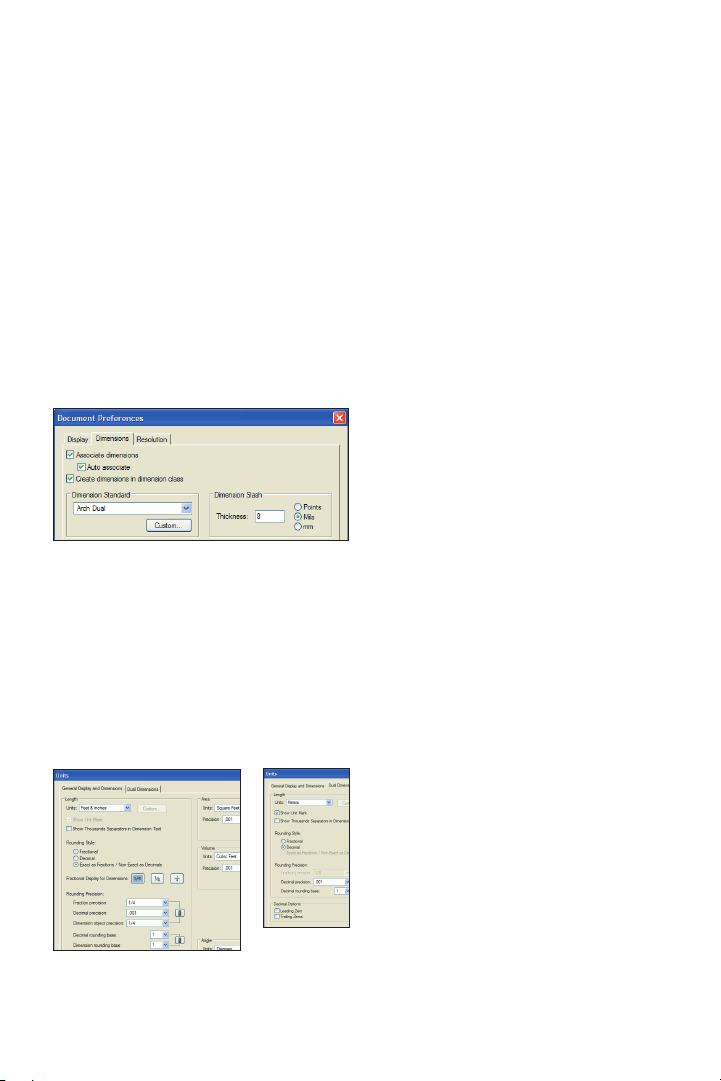
Next, you verify or adjust dimension
creation and precision preferences.
10. Right-click a blank area and select
Document Preferences. In the Document
Preferences dialog box, select the
Dimensions tab. Verify or adjust settings
(8 Mils [.2032mm]) as shown, and then
click OK.
11. From the menu, select File > Document
Settings > Units. In the Units dialog box,
select the General Display and Dimensions
tab. Verify or adjust settings, as shown at
left. Select the Dual Dimensions tab, and
then verify or adjust settings as shown at
right. Click OK to save the settings.
Dimension Notes:
1) Associative dimensions “attach”
themselves to drawing objects by placing
parametric constraints on vertices of selected
geometry. Parametric constraints let dimensions
move and update values when you move or
resize associated geometry, or (for linear and
chain dimensions only) modify associated
geometry if you change the Length parameter.
2) To turn off display of the parametric
constraints, select Tools > Options >
Vectorworks Preferences from the menu, and
then select the Display tab and turn off the Show
Parametric Constraints option (leave the
display on for these exercises).
3) If the Associative Dimensions option is
disabled, any dimensions you create will not be
attached to—or control— geometry you snap to.
4) The Dimension Exterior Walls command
optionally creates associative dimensions, but it
cannot create them for all objects.
5) Refer to the Online Help’s Associative
Dimensioning topic for more information.
6) In your own files, you can create or import
custom dimension standards and use them
individually or replace default standards (in the
active drawing only) if you need to adjust any
parameters such as Offset Text size. Refer to the
Online Help’s Using Custom Dimension
Standards topic for more information.
7) For your own drawings with dimensions
based on multiple standards, you can set the
current dimension standard from the Tool bar
when any dimension tool is active.
Vectorworks Architect 2011 Getting St arted Guide | 19
Page 22
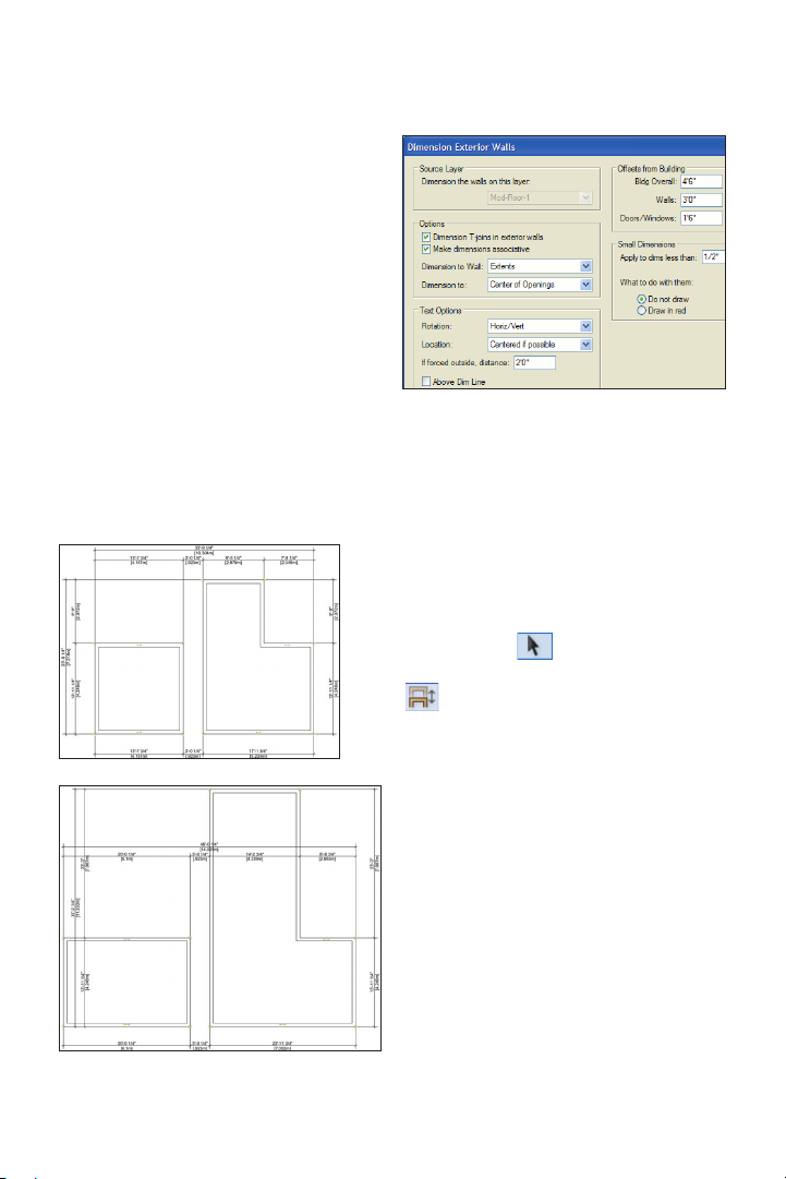
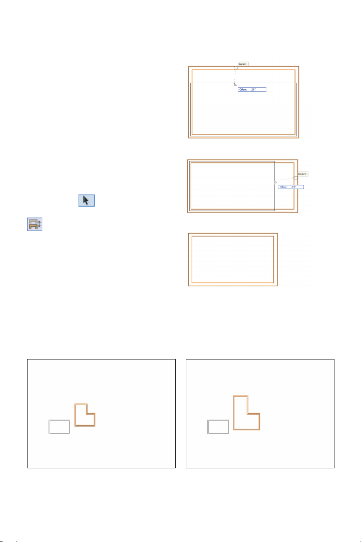
Dimensioning Walls
Next, you use the Dimension Exterior
Walls command to automatically dimension
the rst-oor exterior walls.
12. From the menu, select AEC >
Dimension Exterior Walls. In the
Dimension Exterior Walls dialog box, adjust
settings as shown at right, and then click
OK to create the dimensions. Press the X
key twice to clear the current selection.
Examine the completed dimensions, shown
below (your values will vary; you remove
duplicate dimensions later in this exercise).
Dynamically Adjusting
the Layout
Next, you use different methods to
dynamically resize and reposition the
exterior walls as you continue to rene the
building envelope.
13. From the Basic tools palette, click the
Selection Tool . In the Tool bar, make
sure the Enable Connected Walls Mode
option is active. Drag individual
connected wall segments, starting with the
vertical walls from right to left, and then the
horizontal walls from top to bottom, approximately as shown at left. As you would when
you dynamically rene spatial relationships
in your own designs, try to get within ±1’-0”
[.305m] of the dimensions shown (do not
reposition dimensions until later in this
exercise). Notice that the dimensions update
to reect changes and provide instant
positional and size feedback as you adjust
the layout (leave the Selection Tool active
for the next four steps).
20 | Vectorworks Architect 2011 Getting St arted Guide
Page 23
14. In the Tool bar, click the click the
Enable Connected Walls Mode
option
to disable it, and then make sure the Enable
2D Cursor Rectangular Selection Mode
option is enabled. Draw a marquee
selection as shown at left. Move the entire
selection by dragging any selected wall to
the right until the distance between the
rooms is between 27’-0” [8.230m] and
29’-0” [8.839m], as shown at right (notice
that all selected walls and dimensions move
together). Now that the “closed loop” move
operation is complete, reset the default
status of the Enable Connected Walls
Mode option by pressing the P key to toggle
(enable) it.
Warning: Drag closed loops with the Enable
Connected Walls Mode option disabled
only when all connected walls are selected.
Partial selections will be disconnected from
unselected walls.
Tip: You can use the 2D Reshape tool to
resize subsets of selected walls. For step by step
instructions from the Architect Getting Started
website, see www.nemetschek.net/training/
2011/architect-2011-getting-started-guide.php.
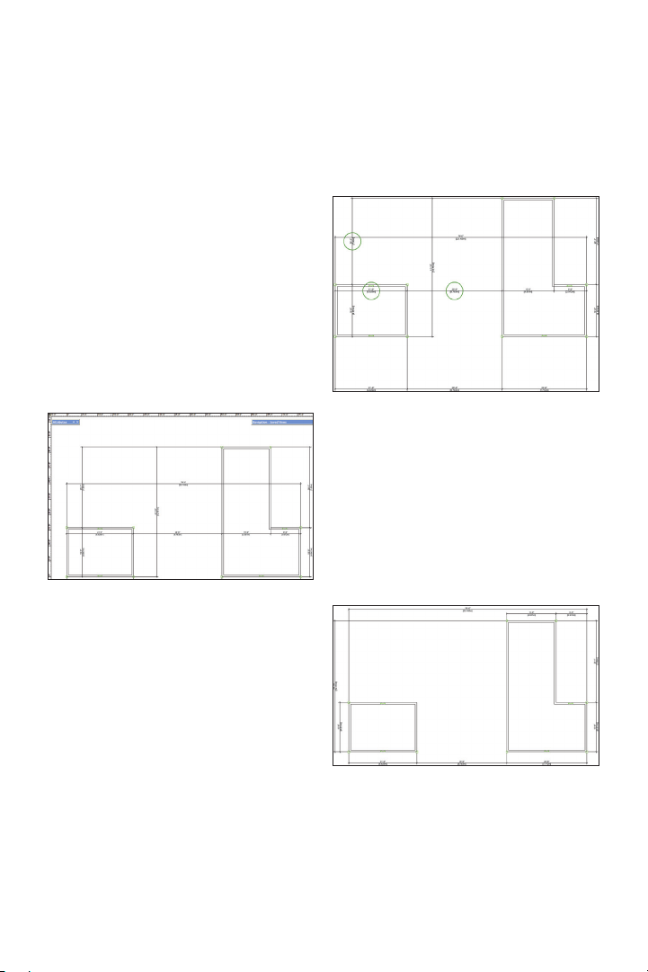
Precisely Adjusting the Layout
Next, you edit the length parameter of key
dimensions to precisely adjust the size and
position of all walls.
15. Double-click the vertical dimension text
to activate editing mode, as shown at the far
left. Click the bottom x point (circled for
clarity) to select it, or press the Tab key
repeatedly to toggle x points until the
bottom x point is selected. Enter a new
value of 15’9” [4.801m], and then press
Enter to accept the new value. The
dimension and walls update to reect the
change, as shown in the next image.
Vectorworks Architect 2011 Getting St arted Guide | 21
Page 24
16. Repeat the length parameter editing
process for the other ve key dimensions in
the order shown. Click or use the Tab key to
control the xed positions (circled, with
corresponding key dimension numbers) as
required (see Note below ).
• Dimension 1: 26'1" [7.950m]
• Dimension 2: 21'9" [6.629m]
• Dimension 3: 28'9" [8.763m]
• Dimension 4: 15'9" [4.801m]
• Dimension 5: 9'9" [2.972m]
Note: Your initial dimensions may vary. If a
dimension edit causes an unintentional change to
another dimension, press Ctrl + Z for the Undo
command shortcut to revert the change, and try
again with a different fix point.
Next, you use the Selection Tool and the
oating data bar to index the house position
with the le's origin.
Note: You move the layout to ensure proper
operation with the supplied exercise checking
file. In your own designs, you may find it helpful
to index the design with the origin for more
meaningful world coordinates (because the entire
design resides in the positive XY quadrant for
Cartesian coordinates), and for more predictable
results when referencing files.
17. From the Basic
tools palette,click the
Select Similar tool
. Click one of
the walls (away from
the dimensions), and
then conrm that all
10 walls are selected
in the Object Info
palette, as shown at
right. Press the X key, and then press the P
key to toggle off Enable Connected Walls
Mode. Start dragging the lower left corner
endpoint (shown below at left; if necessary,
press the Z key and make sure you drag the
endpoint, as shown below at right).
22 | Vectorworks Architect 2011 Getting St arted Guide
Page 25
Move your cursor slightly (do not release the
left mouse button) and then press the Tab
key ve times to highlight the X value in the
oating data bar. Enter 0 (zero) for the value,
and then press the Tab key and enter 0
(zero) for the Y value. Press Enter twice to
move the selected walls. Press the P key to
toggle Enable Connected Walls Mode on,
and press the X key twice to clear the
selection. Press Ctr l + 6 for the Fit to
Objects shortcut to see the entire layout.
Notice that the rulers conrm the lower left
corner is on the origin (0,0), as shown below.
Tip: Use the Snap Loupe whenever you need to
temporarily zoom in and select a point. For best
Snap Loupe performance, press Ctrl + 8, select
the General Category, and then disable the
Zoom Line Thickness in Snap Loupe option.
Next, you delete duplicate dimensions, and
then you reposition the remaining dimensions to clean up the drawing.
18. Right-click the text of the dimensions
circled at left (one at a time), and select
Delete Dimension
from the context menu
to remove them from the drawing. Drag the
remaining dimensions (by dimension lines;
not text) into place, approximately where
shown at top below.
Vectorworks Architect 2011 Getting St arted Guide | 23
Page 26
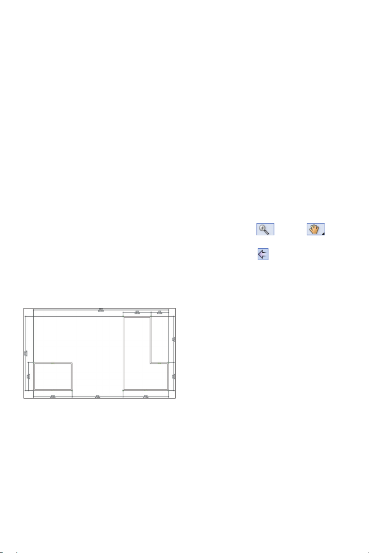
Next, you lock all dimensions to prevent
inadvertent changes.
20. Press the X key twice to clear the selec-
tion, and then press Ctrl + S to save the le.
Note: The walls won’t change position or resize
when you lock all associated dimensions, but you
can still modify wall properties and insert objects
into them.
19. From the menu, select Window >
Script Palettes > Scripts. Drag the Scripts
palette to the left of the Navigation palette,
and then double-click the Custom Select
All Dims script. All dimensions are now
selected. Right-click the text of one of the
dimensions, and select Lock from the
context menu. The selection highlight color
turns gray (and the Object Info palette
updates) to indicate all selected objects are
locked, as below.
If you set up your les as instructed in the
Checking Your Work section (p. 8), you
can now optionally check the accuracy of
your le.
21. Open the (read-only) GS-VWAxCheck.
vwx
le. In the Navigation palette,
double-click the 01 Floor Plan-1 saved view
to activate it, and then double-click the
Check EX03 saved view to activate it.
22. Use the Zoom
and Pan
tools (in the Basic tools palette), and the
Previous View tool
(in the View bar) as
necessary to examine the drawing. Your
drawing objects are displayed in red, and
the master le’s drawing objects are
displayed in their default colors. You should
see your red drawing objects overlaid
directly on top of the master le’s drawing
objects (check dimensions for completeness; ignore dimension alignment).
23.
After checking your le’s accuracy,
close the active le (your House.vwx le
should now be active). If your drawing is
inaccurate, close your le and continue with
the next exercise by starting with the
supplied le.
24 | Vectorworks Architect 2011 Getting St arted Guide
Page 27
Exercise 4: Drawing Interior Walls
In this exercise, you draw and dimension the internal walls. The completed exercise is
shown in the following gure.
Drawing the Functional
Area Walls
You start the exercise by drawing walls
using the 4.5" [114.3mm] Generic Int
placeholder (see p. 16) wall style.
1. If you did not complete Exercise 3—or
you are unsure of your le’s accuracy—
open the GS-VWAx03.v wx le.
2. Press the 9 key for the Wall tool
shortcut. In the Tool bar, select the 4.5”
[114.3mm] Generic Int wall style. To start
the rst segment, move your cursor over the
left vertical wall, and then click the wall
(when it’s highlighted), approximately where
point 1 is shown at left. Complete the rst
segment by holding down the Shift key and
clicking approximately where point 2 is
shown at left. Complete the second
segment by holding down the Shift key to
vertically constrain the cursor, and then
snap to the existing wall approximately
where point 3 is shown at left (when the
exterior wall is highlighted). Notice that the
internal walls were automatically joined at
the corner, and to the existing walls on both
exterior ends, as shown at right (leave the
Wall tool active for the next two steps).
Vectorworks Architect 2011 Getting St arted Guide | 25
Page 28

3. With the Wall tool still active, use the
Shift key to draw two vertical wall segments
and another L-shape series with a corner
connection, approximately where shown
(highlighted for clarity; to start and terminate
connections with existing wall, click when
existing walls highlight).
Drawing the Pantry Wall
Next, you draw a vertical interior wall
segment for the pantry wall.
4. With the Wall tool still active, use the Shift
key to draw a vertical wall segment—from top
to bottom—connected with the vertical
segment, approximately where shown.
Completing a Wall Y-Join with
a Geometric Constraint
Next, you complete a Y-join corner by
connecting the interior pantry wall to the
exterior wall corner with a coincident
constraint.
5. From the Dims/Notes tool set, hold down
the left mouse button on the Constrain
Colinear tool
and then click Constrain Coincident .
Click the top left corner of the pantry wall
segment and then click the inside corner of
exterior walls to connect the vertices by
placing a coincident constraint between
them, as shown.
to open the yout palette,
26 | Vectorworks Architect 2011 Getting St arted Guide
Page 29

Dimensioning Walls
Next, you create linear dimensions, add
dimensions to an existing chain dimension,
and then modify the length values to
precisely position the interior walls.
6. From the Dims/Notes tool set, click
Constrained Linear Dimension
the Tool bar, make sure Constrained Linear
Mode
is active. Snap to the appropriate
wall endpoints (see Notes below gure) to
create two constrained linear dimensions, as
shown (highlighted).
Notes:
1) Snap to the endpoints marked with green
squares, which indicate the parametric constraint
points of associative dimensions.
2) The first two clicks determine dimension
points (if prompted, accept default wall
selections); the third click orients and places the
dimension.
3) Pick up points of existing dimension
geometry, and then use SmartCursor cues to
align new dimensions as you create them.
4) Make sure the dimensions you create are
associative (green squares are displayed on both
ends). If not, press Ctrl + Z and try again.
. In
5) Press the X key, and then drag dimension
lines or text if you need to move either. You can
also select multiple dimension objects, and then
drag their dimensions lines together.
6) In your own drawings, you can dynamically
or precisely adjust witness line lengths for one or
more dimension objects. Refer to the Online
Help’s “Editing Dimensions with the Mouse” and
“Editing Dimension Properties” topics for more
information.
Next, you unlock two of the existing chain
dimensions so you can add dimensions for
the new interior walls.
7. In the Scripts palette, double-click the
Custom Select All Dims script to activate it.
Right-click any of the selected dimensions,
and select Unlock from the context menu.
Leave all dimensions selected, and then
right-click the 25’-6” [7.772m] dimension text
and select Add Dimension from the context
menu (the cursor changes shape to indicate
that the added dimension’s endpoint must be
specied). Snap to the vertical wall’s endpoint
to add a dimension, as shown at left. Repeat
the process to add three more dimensions (to
the right-most dimension) by snapping to
appropriate wall endpoints to complete the
chain dimension, as shown at right.
Vectorworks Architect 2011 Getting St arted Guide | 27
Page 30

8. Press the X key, and then double-click
each dimension and change the values to
match the following gure (change the xed
point as necessary; see Notes below gure).
Notes:
1) You only need to adjust the four left chain
dimensions; the 4’-5” [1.346m] dimension on the
right side will be corrected automatically.
2) If you experience a bug that alters any wall
T-joins when you change dimension values, use
the Wall Join tool with T Join Mode
to re-create the joins.
Next, you lock all dimensions.
9. In the Scripts palette, double-click the
Custom Select All Dims script. Right-click
one of the selected dimensions, and select
Lock from the context menu.
10. Press the X key twice to clear the selec-
tion, and then press Ctrl + S to save the le.
If you set up your les as instructed in the
Checking Your Work section (p. 8), you
can now optionally check the accuracy of
your le.
11. Open the (read-only) GS-VWAxCheck.
vwx
le. In the Navigation palette,
double-click the 01 Floor Plan-1 saved view
to activate it, and then double-click the
Check EX04 saved view to activate it.
12. Use the Zoom
and Pan
tools (in the Basic tools palette), and the
Previous View tool
(in the View bar) as
necessary to examine the drawing. Your
drawing objects are displayed in red, and
the master le’s drawing objects are
displayed in their default colors. You should
see your red drawing objects overlaid
directly on top of the master le’s drawing
objects (check dimensions for completeness; ignore dimension alignment).
13.
After checking your le’s accuracy,
close the active le (your House.vwx le
should now be active). If your drawing is
inaccurate, close your le and continue with
the next exercise by starting with the
supplied le.
28 | Vectorworks Architect 2011 Getting St arted Guide
Page 31

Exercise 5: Drawing Second-Floor
Walls and Adding a Stair
In this exercise, you copy a subset of walls from the Mod-Floor-1 layer, and then you paste
them in-place on the Mod-Floor-2 layer to start the second-oor plan. Next, you clean up
wall intersections, and then you constrain the exterior second-oor walls to the mating
rst-oor walls. You then complete the exercise by inserting a stair object and modifying the
layout to t the stair conguration. The completed exercise is shown in the following gure.
Copying Walls for the
Second-Floor Plan
You start the exercise by copying ten walls,
and then you paste them in place in the Mod-
Floor-2 layer to start the second-oor plan.
1. If you did not complete Exercise 4—or
you are unsure of your le’s accuracy—
open the GS-VWAx04.vwx le.
2. Press Ctrl + 6 to display the entire oor
plan. Press the X key, and then hold down
the Shift key and select the ten walls shown.
Vectorworks Architect 2011 Getting St arted Guide | 29
Page 32

3. In the Object Info palette, verify that ten
walls are selected, and then press Ctrl + C to
copy them. In the Navigation palette, select
the Saved Views tab, and then double-click
the Floor Plan-2 saved view to activate it (in
the View bar, notice the Mod-Floor-2 layer is
now active, as shown at right). From the
menu, select Edit > Paste in Place to copy
the walls to the same X and Y coordinates
on the second oor,
as shown below
Joining Walls
Next, you use the Wall Join tool to clean up
wall intersections and corners.
4. Press the X key twice to clear the current
selection. From the Building Shell tool set,
click Wall Join
in the Tool bar. Click wall segments in
order, approximately where shown The wall
corners are joined and trimmed, as shown.
, then click L Join Mode
Important: Avoid clicking too close to the end
of each wall segment. If you click at the end of
the segment, the walls will not join properly.
Note: If you experience a bug that alters any
existing wall joins in the previous or next steps,
use the Wall Join tool with either
L Join Mode or T Join Mode as
appropriate to re-create the join.
5. With the Wall Join tool still active, click
wall segments 1 and 2 in order, approximately where shown at left, and then click T
Join Mode
in the Tool bar. Click wall
segments 3 through 8 in order, approximately where shown at left. Press the X key
twice to clear the current selection. You can
now see that all wall corners are appropriately joined and trimmed, as shown at right.
Note: To save time, you skip the repetitive
process of applying geometric constraints to the
second floor walls to link their length and position
with mating walls on the first floor. If you want to
apply these optional constraints or learn about
related design benefits not covered in this
tutorial, save your file now and refer to the
step-by-step instructions from the Architect
Getting Started website; see www.nemetschek.
net/training/2011/architect-2011-getting-started-
guide.php. After applying the constraints, you can
continue with the next step.
30 | Vectorworks Architect 2011 Getting St arted Guide
Page 33

Drawing Remaining Walls
Next, you draw the remaining interior
second-oor walls in their approximate
positions.
6. From the Building/Shell tool set, click
Wall . In the Tool bar, make sure the
4.5” [114.3mm] Generic Int wall style is still
active. Use the Shift key to draw the
remaining the interior walls approximately
where shown (highlighted for clarity).
Dimensioning Walls
Next, you use the same dimension/
modication technique as the previous two
exercises (with minimal instruction) to
complete the second oor layout.
7. Use either the Dimension Exterior Walls
command or the Constrained Linear
Dimension tool
Chain Mode
to create associative dimensions, and then
change the length and xed points as
necessary to precisely position the interior
walls from the previous step, as shown at
right (with chain dimensions).
with Constrained
(see Notes below gure)
Notes:
1) The dimensions shown are the only
dimensions required to complete the second-floor
interior wall layout (see Note 3). The other walls
were copied from the first floor and pasted in the
correct position on the second floor. To save time
in this exercise, you skip the repetitive process of
creating dimensions for all second-floor walls
normally required for construction documentation.
2) To automatically associate dimensions with
T-joined wall intersections with the Dimension
Exterior Walls command, select Centerlines
from the Dimension to Wall drop-down list, and
select Center of Openings from the Dimension
drop-down list in the Dimension Exterior Walls
dialog box. If you prefer dimensions to wall
edges, use the Constrained Linear Dimension
tool , and double-click the snap point in the
chain to terminate the dimension string.
3) If you applied the optional constraints after
step 5 (p. 30), any dimensions associated with
second-floor exterior walls will also control
mating (constrained) walls on the first floor, even
though the first-floor walls already have
dimensions associated with them. Vectorworks
allows multiple-dimension control (from
dimensions in design layers and sheet layer
viewport annotations) over associated objects.
Vectorworks Architect 2011 Getting St arted Guide | 31
Page 34
Inserting a Stair Object
Next, you insert a custom stair plug-in
object. You then drag and nudge the stair
object into position.
8. In the Navigation palette, double-click
the Floor Plan-1 saved view to activate it. In
the Scripts palette, double-click the Toggle
Dimension Class Visibility script to hide
all dimensions.
Note: You can use the Toggle Dimension
Class Visibility
exercises to check dimensions or hide them to
reduce clutter.
9. From the Building Shell tool set, click
Custom Stair
Wall Insertion Mode , if it’s active, to
turn it off, and then enable the Align Object
Left
then snap to the wall edge, where shown.
script at any time in any of the
. In the Tool bar, click
option. Snap rst to the corner and
corner of the platform and releasing it on
the top right inside corner of the stairwell,
as shown at right.
Note: The Custom Stair tool was pre-configured
for this file. The Stair Settings dialog box would
normally be displayed for the first custom stair
object inserted in a file. For subsequent
insertions in your own files, click Preferences
from the Tool bar before placing the custom
stair to set default parameters. If you change
Stair Settings dialog box parameters, all
subsequent insertions are affected.
The stair object is created (shown above at
left). Press the X key, and then move the
stair object by dragging the upper right
32 | Vectorworks Architect 2011 Getting St arted Guide
10. Zoom in on the stairs by pressing Ctrl +
6 for the Fit To Objects shortcut, and then
hold down the Shift key and press the Left
and Down arrow keys one time each to
make sure the stairs are close to the walls
but not touching them, as shown above.
Page 35

Modifying the Stairwell, Foyer,
and Deck Walls
Next, you shorten the stairwell divider wall
to accommodate the stair platform and
handrails.
11. From the View bar, click Previous View
, and then press the X key and select the
stairwell divider wall below the stair (notice
the selection highlight is visible under the
stair object). Click the top grip when the
resize cursor
is displayed to “pick up” the endpoint (do not
snap to another point after you click the top
grip, or the wall will not remain vertical).
Move your cursor, press the Tab key three
times and enter 0 for the ±X value, and then
press Enter. Notice the vertical constraint
indicator, as shown at top left. Move your
cursor to the inside edge of the horizontal
stair handrail, and then press the Z key for
the Snap Loupe shortcut (to temporarily
and SmartCursor point cue
zoom in). Click the
midpoint of the stair
handrail’s inside
edge to resize the
wall (and close the
Snap Loupe), as
shown at top right. In
the Object Info
palette, select Start
from the Caps
drop-down list, as
shown at left.
Click in a blank area
of the drawing to clear
the selection and
examine the wall cap,
shown at right.
Next, you use the 2D
Reshape tool to
shorten the kitchen
wall’s left edge to
make a 3’ wide
opening into the foyer.
Vectorworks Architect 2011 Getting St arted Guide | 33
Page 36

12. In the Scripts palette, double-click the
Toggle Dimension Class Visibility script to
show all dimensions. Right-click the 6’-2 1/4”
[1.886m] dimension and select Unlock from
the context menu. From the Basic tools
palette, click 2D Reshape
. Make sure
that the Move Polygon Handles Mode
is active in the Tool bar. Select the horizontal
kitchen wall. Click the left grip to “pick up” the
endpoint, and then move the cursor to display
the oating data bar. Type 3’ for the ±X value,
press Tab and enter 0 (zero) for the ±Y value,
and then press Enter twice to complete the
reshape operation, as shown at top. In the
Object Info palette, select Start from the
Caps drop-down list. From the Building Shell
tool set, click Remove Wall Breaks
.
Draw a marquee from lower left to upper right,
approximately as shown at bottom left (see
Note below gure). Notice that the wall break
was removed (the wall line is now continuous). Lock the 6’-2 1/4” [1.886m] dimension,
and then press the X key twice to clear the
selection. Examine the shortened wall, as
shown at bottom right.
13. In the Navigation palette, double-click
the Floor Plan-2 saved view to activate it.
Notice that the custom stair object inserted
in the Mod-Floor-1 layer is also displayed in
the (currently active) Mod-Floor-2 layer. In
the Scripts palette, double-click the Toggle
Dimension Class Visibility script to hide
dimensions. Press the X key twice, and then
hold down the Shift key and select the six
walls shown below. In the Object Info
Note: Remove only the wall break of the vertical
wall (do not remove the wall break on the left
edge of the horizontal kitchen wall).
Next, you change the height of the deck and
stairwell walls to make balustrade walls. You
then shorten the stairwell wall.
34 | Vectorworks Architect 2011 Getting St arted Guide
Page 37

palette, disable the
Link Wall Height to
Layer ±Z option,
and then change the
±Z value (3’0”
[.914m]), as shown.
Click a blank area, and
then select the stairwell
wall. Click the top grip,
hold down the Shift key,
and then click the right
front stair edge to resize
the wall. Use the
Remove Wall Breaks
tool to remove the
break at the resized
end, and then select Start from the Caps
drop-down list in the Object Info palette to
complete the stairwell wall, as shown at left.
14. In the Scripts palette, double-click the
Toggle Dimension Class Visibility script
to show the dimensions. Press the X key
twice to clear the selection, and then press
Ctrl + 6 to adjust the display. Examine the
completed second-oor walls, as shown.
15. Save the le.
If you set up your les as instructed in the
Checking Your Work section (p. 8), you
can now optionally check the accuracy of
your le.
16. Open the (read-only) GS-V WAxCheck.
vwx
le. In the Navigation palette, double-
click the 01 Floor Plan-1 saved view to
activate it, and then double-click the Check
EX05 saved view to activate it.
17. Use the Zoom
and Pan tools
(in the Basic tools palette), and the Previous
View tool
(in the View bar) as necessary
to examine the drawing. Your drawing objects
are displayed in red, and the master le’s
drawing objects are displayed in their default
colors. You should see your red drawing
objects overlaid directly on top of the master
le’s drawing objects.
18. In the Navigation palette, double-click
the 02 Floor Plan-2 saved view to activate it,
and then double-click the Check EX05 saved
view to activate it.
19. Use the Zoom
and Pan tools
(in the Basic tools palette), and the Previous
View tool
(in the View bar) as necessary
to examine the drawing. Your drawing
objects are displayed in blue, and the master
le’s drawing objects are displayed in their
default colors. You should see your blue
drawing objects overlaid directly on top of the
master le’s drawing objects.
20. After checking your le’s accuracy, close
the active le (your House.vwx le should
now be active). If your drawing is inaccurate,
close your le and continue with the next
exercise by starting with the supplied le.
Vectorworks Architect 2011 Getting St arted Guide | 35
Page 38

Page 39

Section 3: Creating
Architectural Elements
In two exercises, this section covers the following processes in the home design project:
•
Creating Floor Slabs from the First-Floor Exterior Walls (p. 38)
• Saving Settings for the Select Similar Tool (p. 39)
•
Changing Foor Slab Properties (p. 40)
• Inserting Doors (p. 41)
• Copying a Door Using Ctrl + Drag (p. 41)
• Creating Different Door Types (p. 42)
• Creating a Cased Opening (p. 44)
• Inserting Windows (p. 44)
• Examining the Design in a 3D View (p. 46)
• Saving a 3D Reference View (p. 47)
•
Creating Floor Slabs from the Second-Floor Exterior Walls (p. 48)
• Copying and Inserting the Remaining Doors and Windows (p. 49)
• Examining the Design in Various 3D Views (p. 52)
In these exercises, you continue working in 2D oor plans (on design layers) as you:
• Create auto-bounded oor slabs from existing walls.
• Rene the house design by inserting a variety of architectural elements (intelligent
plug-in objects).
After inserting architectural elements, you use simple view controls to examine the 3D
objects that were created automatically by the 2D tools.
Vectorworks Architect 2011 Getting St arted Guide | 37
Page 40

Exercise 6: Creating
the First-Floor Plan
In this exercise, you create slab objects, and then you place common architectural elements
in the rst-oor plan. The completed exercise is shown in the following gure:
Creating Floor Slabs from the
First-Floor Exterior Walls
You start by creating two auto-bounded
oor slab objects from the rst oor’s
exterior walls using the Ground slab style.
As you did with wall styles (see p. 16),
you use this slab style as a unique
placeholder for the rst oor’s slabs until
you replace them with the nal conguration
in Exercise 9 (p. 60).
38 | Vectorworks Architect 2011 Getting St arted Guide
1. Open the GS-VWAx05.vwx le in the
Data Set folder. In the Navigation palette,
activate the Floor Plan-1 saved view. In the
Scripts palette, double-click the Toggle
Dimension Class Visibility script to hide
all dimensions.
Page 41

2. From the Building Shell tool set, click the
Slab tool
Picked Walls Mode , and then select
Ground from the Slab Style drop-down list.
In the drawing area, click the four storage
(rectangular) room walls, and then click
Press to Complete Operation
Tool bar to create the slab, as shown at top
right. With the Slab tool still active, click the
six exterior walls that form the L-shaped
perimeter of the functional area and living
room, and then click Press to Complete
Operation
shown at bottom right.
Notice that even though both slab objects
reside below the Z height of the walls, they
are displayed on top of them due to the
creation order (or stacking order) of objects
in the Mod-Floor-1 layer.
. In the Tool bar, enable
in the
to create the slab, as
Saving Settings for the Select
Similar Tool
Next, you save two congurations of
attribute matching settings for the Select
Similar tool.
3. From the Basic tools palette, click the
Select Similar tool
click Select Similar Preferences . In
the Select Similar Preferences dialog box,
verify or adjust settings as shown below.
. In the Tool bar,
In the Selection
Options section, click
Save. In the Assign
Name dialog box,
enter Object for the
name, as shown.
Click OK to save the settings. Notice that the
Object saved setting is now displayed in the
Use Saved Settings drop-down list (and is
now active), as shown at left. Keep the
Select Similar Preferences dialog box open.
Vectorworks Architect 2011 Getting St arted Guide | 39
Page 42

4. In the Other
section, enable the
Class option, as
shown above. Click
Save and save the
settings as Class
and Object, as shown. With the new Class
and Object saved setting active (as shown
at top right), click OK to save the settings
(leave the Select Similar tool active).
Changing Floor
Slab Properties
Next, you change the slab objects’ class
and layer properties.
5. With the Select Similar tool still active,
click either of the two slab objects. In the
Object Info palette conrm that two slabs
are selected and then change the following:
• Slab objects' class property to
Structural-Slab (if a message dialog box is
displayed, enable the Always do the
selected action option, and click Yes).
• Slab objects' layer property to
Mod-Slab-1. The slab objects seemingly
disappear (see Note below gure) but are
actually present under the walls because of
the layer order saved in the Floor Plan-1
view, as shown.
Note: The slab objects no longer appear selected
because of the Floor Plan-1 saved view’s layer
option settings. If you were to activate the
Mod-Slab-1 layer (do not activate it now), you
would see that the floor object is still selected.
40 | Vectorworks Architect 2011 Getting St arted Guide
Page 43

Inserting Doors
Next, you use the Door tool to insert a
plug-in object.
6. Zoom in on the
kitchen and functional
area, as shown at left.
From the Building Shell
tool set, click the Door tool
• Click the foyer
wall approximately
where shown at left.
• Move your cursor
to orient the door as
shown below at left
(notice how your cursor
position ips the door
side and swing), and
then click to place the door plug-in object,
as shown below at right.
Note: The Door tool was pre-configured for this
file. The Door Settings dialog box would normally
be displayed for the first door object inserted in a
file. For subsequent insertions in your own files,
click Preferences from the Tool bar before
placing the door to set default door parameters. If
you change the Door Settings dialog box
settings, all subsequent insertions are affected.
.
7. In the Object Info
palette, verify a
“Door In Wall” is
selected (as shown).
If it isn't drag the
door to reinsert it in
the wall. Leave the
door selected for the
next step.
Copying a Door
Using Ctrl + Drag
Next, you create two more doors by copying
the existing door object dynamically by
dragging it while pressing the Ctrl key.
8. Hold down the Alt key, and then click
Zoom In/Zoom Out
necessary) until the storage room is visible.
Press the X key, and then hold down the
Shift and Ctrl keys and drag the foyer door
(drag it from its insertion point: the middle of
the door’s wall break) to create a copy
(highlighted at left) in the storage room wall.
If your copied door doesn’t break the wall, try
again and release the mouse button when
the Object/Horizontal SmartCursor cue is
displayed. In the Object Info palette, click the
Flip button one time to change the swing as
shown. Hold down the Ctrl key, and drag the
foyer door to create the front door, approximately where shown (highlighted) at right.
(repeatedly if
Vectorworks Architect 2011 Getting St arted Guide | 41
Page 44

Creating Different Door Types
Next, you copy one of the 3’-wide door
objects and then modify the copy to create a
door that is 2’6” [.762m] wide.
9. Press the X key
twice, and then use
the Ctrl + drag
method to copy the
front door (by its
insertion point: the
midpoint of its wall
break) to the center
of the stairwell
closet wall, as
shown above at left.
In the Object Info
palette (shown at
right), adjust the new
door’s settings:
• Change the
Door Width to 2’6”
[.762m].
• Change the
Door Height to 6’8”
[2.032m].
• Change the
Open Angle to 15, and then press Enter to
incorporate the change.
• Click the Flip button as necessary to
orient the door as shown above at right.
Note: You change the open angle to 15 degrees
so you can easily distinguish the 2’6” [.762m]-
wide door.
10. Zoom in on the
area shown at left.
Press the X key, and
then use the Ctrl + drag
method to copy the
stairwell closet door to
the bathroom wall,
approximately where
shown below.
42 | Vectorworks Architect 2011 Getting St arted Guide
Page 45

Next, you use the same copy and modify
method to create a bi-part pantry door and
slider doors for the living room.
11. Use the Ctrl + drag method to copy the
bathroom door to the pantry wall, as shown
below at left. In the Object Info palette,
change the following details of the new door.
• Width to 2’0” [.610m]
• Conguration to Swing Bi-part
• Open Angle to 30
Drag the bi-part door if necessary to
reposition it, and then use the Ctrl + drag
method to create a second bi-part door in
the pantry wall, approximately where shown
(highlighted) below at right.
12. Use the Ctrl +
drag method to copy
the 3’ [.914m]-wide
foyer door to the left
living room wall,
approximately where
shown below at left.
In the Object Info
palette, edit the new
Door Width (7’0”
[2.134m]) and
Conguration
properties, as
shown. Use the Ctrl + drag method to create
a copy above, and then select both and use
Shift + Ctrl + Drag to copy both to the
opposite wall to create a total of four slider
doors in the orientations (use the Flip option
as necessary) and approximate positions,
as shown below at right.
Vectorworks Architect 2011 Getting St arted Guide | 43
Page 46
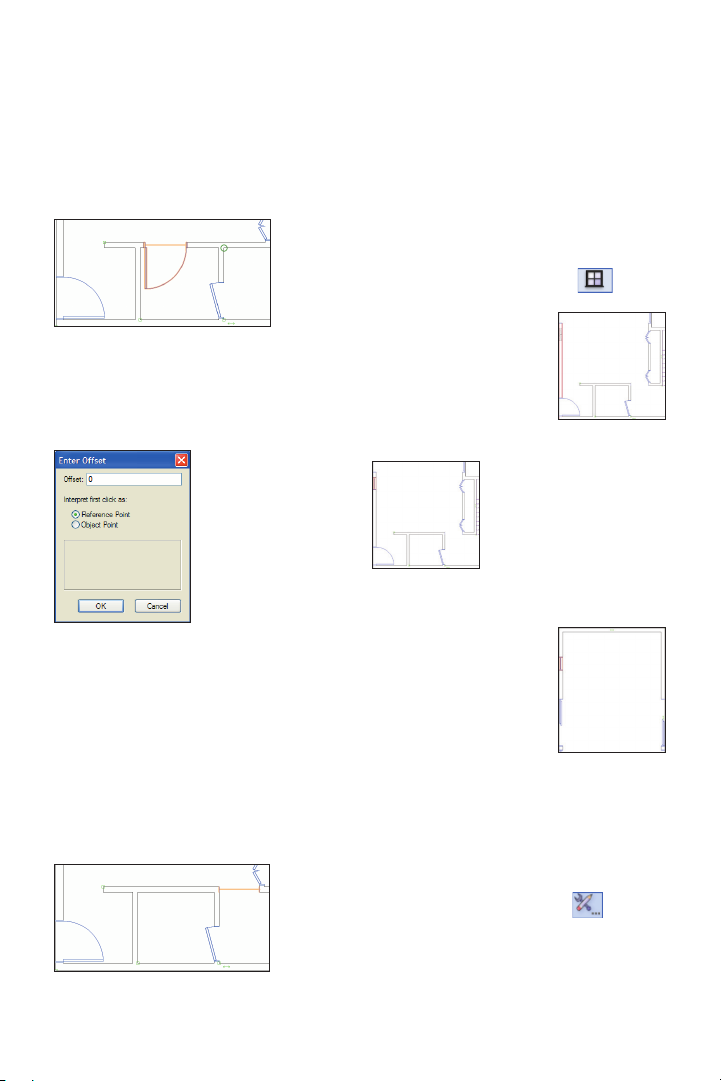
Creating a Cased Opening
Next, you use the 3’-wide door to create a
cased opening.
13. Use the Ctrl + drag method to copy the
3’-wide foyer door to the horizontal
bathroom wall, approximately where shown
above. In the Object Info palette:
• Change the
Conguration to
Cased Opening.
• Scroll down,
and change the
Jamb Width to 0
(zero) and press
Enter to incorporate
the change.
• Scroll up and click Set Position. Click
the wall corner (circled at left) for the
reference point, and then click the cased
opening’s lower left vertex for the object
point. Adjust settings in the Enter Offset
dialog box, as shown above at left. Then
click OK to set the cased opening’s jamb
ush with the wall edge, as shown below.
Inserting Windows
Next, you activate the Window tool, and
then you insert two windows.
14. Press the X key twice to clear the
selection, and then from the Building Shell
tool set, click the Window tool
• Click once to
position the window in
the left kitchen wall,
approximately where
shown at right.
• Click outside and
to the left of the kitchen
to specify the rotation.
The window plug-in
object is created, as
shown at left
• With the Window
tool still active, insert
another window in the
wall (click outside to
specify rotation), as
shown at right.
Note: The Window tool was pre-configured for
this file. The Window Settings dialog box would
normally be displayed for the first window object
inserted in a file. For subsequent insertions in
your own files, click Preferences from the
Tool bar before placing the window to set default
window parameters. If you change the Window
Settings dialog box settings, all subsequent
insertions are affected.
.
44 | Vectorworks Architect 2011 Getting St arted Guide
Page 47

Next, you change properties of the last
window to create a 7’ [2.134m]-wide picture
window.
15.
With the window still selected, conrm
in the Object Info palette that the window is
in the wall, and then:
• Change the Overall Width to 7’0”
[2.13 4 m].
• Change the Overall Height to 8’0”
[2.438m].
• Scroll down and change the Num V
Muntins to 1.
• Change the Muntin Width to 4”
[101.60mm].
• Change the Muntin Depth to 1”
[25.40mm], and then press Enter to update
the window settings.
• Drag the window so that its outside
top jamb edge is ush with the inside edge
of the living room wall, as shown at right.
16. Press the X key, and then use the Shift
+ Ctrl + drag method (and the Ctrl + drag
method) to copy the 7’ [2.134m]-wide picture
window seven times (highlighted for clarity)
for a total of eight picture windows, as
shown below (see Note).
Note: Ctrl + drag automatically orients window
exteriors.
Vectorworks Architect 2011 Getting St arted Guide | 45
Page 48

Next, you copy the 2’ [.610m]-wide window.
17. Use the Ctrl + drag method to copy the
small window one time, and then select both
and use Ctrl + drag to copy both windows to
create a total of four 2’ [.610m]-wide
windows, approximately where shown
(highlighted for clarity).
Note: In your own designs, you would now create
associative dimensions for the windows and
doors, (and edit length values as necessary). To
save time, you skip this step in this exercise and
in Exercise 7. Instead, you optionally create
window and door dimensions later in Exercise 11
(p. 81).
Examining the Design in
a 3D View
Next, you activate different 3D views so you
can examine the architectural elements you
just inserted.
18. From the menu, select View >
Standard Views > Top. Press the X key
twice, and then press Ctrl + 6 to adjust the
display. Notice that 2D object details (such
as door swings and wall breaks) disappear
in this 3D top view, as shown at top left.
From the View bar, select the
Isometric view from the Standard View
drop-down list, and then press Ctrl + 6 to
adjust the display. The viewing angle is
changed, as shown at bottom left.
Notice that even though you were previously
working in 2D, Vectorworks Architect
automatically created 3D objects.
Note: Do not be concerned about the inappropri-
ate single hung windows; you change properties
of all windows later in Exercise 9 (p. 60).
Left
46 | Vectorworks Architect 2011 Getting St arted Guide
Page 49

Saving a 3D Reference View
Next, you save a view with the current
display attributes that you use in other
exercises later in the tutorial.
19. In the Navigation palette, select
the Saved Views
tab, and then
right-click the blank
area below the list
and select New. In
the Save View dialog
box, change the
View Name and
Layer Options, and
conrm (or adjust) other settings as shown
at top right, and then click OK to save the
view. Notice that the new view is now
displayed in the list with the 3D view icon
, as shown at bottom right.
20. In the Navigation palette, activate the
Floor Plan-1 saved view, and then press
Ctrl + 6 to adjust the display, as shown.
Tip: You can optionally create a design layer
section viewport (with an offset section line) to
examine the house in a 3D cutaway view as the
design evolves. For step by step instructions
from the Architect Getting Started website, see
www.nemetschek.net/training/2011/architect-
2011-getting-started-guide.php.
21. Save the le.
If you set up your les as instructed in the
Checking Your Work section (p. 8), you
can now optionally check the accuracy of
your le.
22. Open the (read-only) GS-V WAxCheck.
vwx
le. In the Navigation palette,
double-click the 01 Floor Plan-1 saved view
to activate it, and then double-click the
Check EX06 saved view to activate it.
23. Use the Zoom
and Pan
tools (in the Basic tools palette) and the
Previous View tool
(in the View bar) as
necessary to examine the drawing. Your
drawing objects are displayed in red, and the
master le’s drawing objects are displayed in
their default colors. You should see your red
drawing objects overlaid directly on top of
the master le’s drawing objects.
24. After checking your le’s accuracy,
close the active le (your House.vwx le
should now be active). If your drawing is
inaccurate, close your le and continue with
the next exercise by starting with the
supplied le.
Vectorworks Architect 2011 Getting St arted Guide | 47
Page 50

Exercise 7: Creating the
Second-Floor Plan
In this exercise, you use a variety of 2D and 3D tools and techniques to complete the
second-oor plan. The completed exercise is shown in the following gure:
Creating Floor Slabs from the
Second-Floor Exterior Walls
You start by creating two auto-bounded
oor slab objects from the second oor’s
balustrade and exterior walls using the
Mechanical placeholder (see p. 38)
slab style.
1. If you did not complete Excercise 6—or
you are unsure of your le’s accuracy—
open the GS-VWAx06.v w x le.
2. In the Navigation palette, activate the
Floor Plan-2 saved view. In the Scripts
palette, double-click the Toggle Dimension
Class Visibility script to hide all dimen-
sions. Press the X key twice to clear the
current selection, and then press Ctrl + 6 to
adjust the display.
48 | Vectorworks Architect 2011 Getting St arted Guide
3. From the Building Shell tool set, click the
Slab tool
that Picked Walls Mode is enabled,
and then select Mechanical from the Slab
Style drop-down list. Click the three
balustrade walls and the bordering exterior
wall, and then click Press to Complete
Operation
shown at left. With the Slab tool still active,
repeat the process with the same slab style
to create the second oor slab from the four
. In the Tool bar, make sure
to create the deck slab, as
exterior second
oor walls, as
shown at right.
Page 51

4. Hold down the Shift key, and then select
the other second oor slab object (both
should now be selected). In the Object Info
palette, change the Slab objects’ Class
property to Structural-Slab and their Layer
property to Mod-Slab-2 to correct the
display order, as shown.
Notes:
1) You notch the second-floor slab to accom-
|modate the stairwell later in Exercise 9 (p. 60).
2) You could combine the deck floor slab with
the second-floor slab, but they are created
separately in this tutorial because of their
structural and functional differences.
3) Although the deck sur face would normally
have a slightly lower elevation than the floor
surface for drainage purposes, they are both the
same elevation (both slabs are the same
thickness) in this tutorial for display purposes.
4) To save time in this tutorial, you ignore the
overlapping area between both slab objects. If you
want to fix this in your model, you can optionally
create a virtual wall segment as a surrogate
auto-boundary for the slab. To do this, delete the
deck slab you just created, and then draw a
horizontal virtual wall segment (with zero height)
connected to the vertical balustrade walls slightly
above the horizontal exterior wall. Create the
auto-bounded slab by picking all three balustrade
walls and the virtual wall, and then change the
slab’s class and layer properties. Use the
Constrain Colinear tool to place a collinear
constraint between the virtual wall and the outside
edge of the second floor’s exterior wall.
Copying and Inserting the
Remaining Doors and Windows
Next, you copy doors and windows from the
rst oor (that you created in Exercise 6),
and then you copy and modify them as
necessary to complete the second-oor plan.
5. In the Navigation palette, activate the
Floor Plan-1 saved view. Press the X key
twice, and then right-click one of the bi-part
pantry doors, and select Create Similar
Object from the context menu. If a message
dialog box is displayed (as shown), enable
the Don’t show this dialog again option,
and then click OK. In the Navigation palette,
activate the Floor Plan-2 saved view. Insert
the bi-part door into
the middle of the hall
closet wall and orient
it as shown at right.
Vectorworks Architect 2011 Getting St arted Guide | 49
Page 52

6. Press the X key,
and then use the Ctrl
+ drag method to
copy the bi-part door
into the guest bedroom closet wall, as
shown above (use the Flip option if
necessary). With the new closet door still
selected, change the Door Width to 4’2”
[1.270m] in the Object Info palette. Drag the
new door into position, as shown below at
left. Use the Ctrl + drag method to copy the
4’2” [1.270m] door, approximately where
shown below at right.
7. Repeat the Create Similar Object
process (step 5) to create a 2’6” [.762m]-wide
door from the rst oor and position it in the
middle of the second oor’s master bedroom
hallway wall and orient it as shown above at
top. Press the X key, and then use the Ctrl +
drag and Flip option to copy the 2’6”
[.762m]-wide door four times (highlighted for
clarity) in the orientations and approximate
locations as shown above at right.
8. Repeat the Create Similar Object
process to create a 7’ [2.134m] slider door
from the rst oor and position it in the
second oor’s family room wall and orient it
as shown at left. Press the X key, and then
use the Ctrl + drag method to create an
adjacent copy of the 7’ [2.134m] slider,
approximately where shown at right. Use
the Flip control as necessary.
9. Repeat the Create Similar Object
process to create a 7’ [2.134m]-wide picture
window from the rst-oor plan and position
it in the second oor’s master bedroom wall,
and then click outside the wall to orient it as
shown at left. Use the Ctrl + drag method to
copy the 7’ [2.134m]-wide picture window
eight times, approximately where shown at
right (highlighted for clarity).
50 | Vectorworks Architect 2011 Getting St arted Guide
Page 53

10. Repeat the Create Similar Object
process to create a 2’ [.610m]-wide window
from the rst-oor plan and position it in the
second oor’s master bedroom hallway wall,
and then click outside the wall to orient it as
shown (leave the window selected for the
next three steps).
Tip: In your own designs, you can adjust layer
visibilities (with Show/Snap Others layer mode
active), and then Ctrl + Alt + click objects on other
layers to activate the Create Similar Object
command.
Next, you use the Move by Points tool to
precisely move and copy the 2’-wide
window in the master bedroom hallway wall
to complete the oor plan.
12. Press Shift + M for the Move by Points
tool shortcut. In the Tool bar, enable Move
Mode
. For the start point, click the
selected window’s midpoint, as shown below.
For the end point, click the insertion point of
the master bedroom walk-in closet’s door, as
shown at left. The window stays in the wall
and is now centered with the walk-in closet’s
door, as shown at right (leave the window
selected for the next step).
11. Zoom in on the area shown.
Vectorworks Architect 2011 Getting St arted Guide | 51
Page 54

13. With the Move by Points tool still active,
snap to the same midpoint on the window as
the previous step, and then hold down the
Ctrl key and snap to the insertion point of the
master bathroom door’s opening, as shown
at left. The window is copied, and the copy is
now centered with the master bathroom’s
opening, as shown at right (leave the copied
window selected and the Move by Points
tool active for the next step).
Note: Holding down the Ctrl key temporarily
enables the Retain option for the original object.
Note: In your own designs, you would now create
associative dimensions for the windows and
doors (and edit length values as necessary). To
save time, you skip this step in this exercise (as
you did in Exercise 6). Instead, you optionally
create window and door dimensions later in
Exercise 11 (p. 84).
Examining the Design in
Various 3D Views
Next, you edit the Unied Isometric saved
view to display additional layers and
classes, and then you examine the new
elements with the Flyover tool.
15. In the Navigation palette, activate the
Unied Isometric saved view. Press the X
key twice to clear the selection. Notice that
the saved view does not show objects on
the second oor, as shown.
14. Use either the Ctrl + drag method or the
Move by Points tool
to create fourteen
additional copies of the 2’-wide window,
where shown (highlighted for clarity).
52 | Vectorworks Architect 2011 Getting St arted Guide
Page 55

16. In the Navigation palette,
right-click the
Unified Isometric
saved view and
select Edit. In the
Edit Saved View
dialog box, click Layers. Adjust visibilities
as shown at right, and then click OK. Click
Classes, and turn on visibility of the
Roof-Main class. Click OK twice to save
the edits. Double-click the saved view to
see the change, and then press the X key
twice to clear the selection, as shown.
17. From the Basic tools palette, click the
Flyover tool
. In the Tool bar, make
sure Interactive Origin Mode is
enabled. Start dragging the cursor to
dynamically examine the model. Press Ctrl
+ 6 to re-center the view. Click to stop the
motion, and change the center of rotation by
clicking on various object vertices (on the
active layer), and then continue dragging the
cursor to change the viewing angle.
18. In the Navigation palette, activate the
Note: To save time, you just turned on visibility
for objects that don’t exist yet, but you create
them later in the tutorial.
Vectorworks Architect 2011 Getting St arted Guide | 53
Page 56

Floor Plan-2 view. From the menu, select
View > Align Layer Views. In the Scripts
palette, double-click the Toggle Dimension
Class Visibility script to hide all dimen-
sions. Press Ctrl + 6 to adjust the display.
19.
Save the le.
If you set up your les as instructed in the
Checking Your Work section (p. 8), you
can now optionally check the accuracy of
your le.
20. Open the (read-only) GS-VWAxCheck.
vwx
le. In the Navigation palette,
double-click the 02 Floor Plan-2 saved
view to activate it, and then double-click the
Check EX07 saved view to activate it.
21. Use the Zoom
and Pan
tools (in the Basic tools palette), and the
Previous View tool
necessary to examine the drawing. Your
drawing objects are displayed in blue, and
the master le’s drawing objects are
displayed in their default colors. You should
see your blue drawing objects overlaid
directly on top of the master le’s drawing
objects.
22.
After checking your le’s accuracy,
close the active le (your House.vwx le
should now be active). If your drawing is
inaccurate, close your le and continue with
the next exercise by starting with the
supplied le.
(in the View bar) as
Section 4:
54 | Vectorworks Architect 2011 Getting St arted Guide
Page 57

Section 4: Working with
Multiple Levels
In two exercises, this section covers the following processes as you continue the home
design project:
• Saving a “Working” View for the Roof (p. 56)
• Creating the Ceiling Slab (p. 57)
• Creating the Roof (p. 57)
• Creating Gabled Ends on the Slanted Roof (p. 58)
• Fitting Walls to the Roof (p. 58)
• Examining the Completed Roof (p. 60)
• Editing Windows (p. 61)
• Creating a Corner Window (p. 62)
•
Notching the Second Floor’s Floor Slab (p. 62)
• Replacing Wall Styles (p. 64)
• Creating Wall End Caps (p. 65)
• Replacing Slab Styles (p. 67)
In these exercises, you:
• Create a ceiling slab for the top oor and a slanted roof by modifying default roof
edge settings.
• Fit affected walls to the slanted roof.
• Modify windows.
• Convert two windows into a corner window.
• Notch the second oor’s oor slab.
• Replace the placeholder wall and slab styles and create wall end caps.
Vectorworks Architect 2011 Getting St arted Guide | 55
Page 58
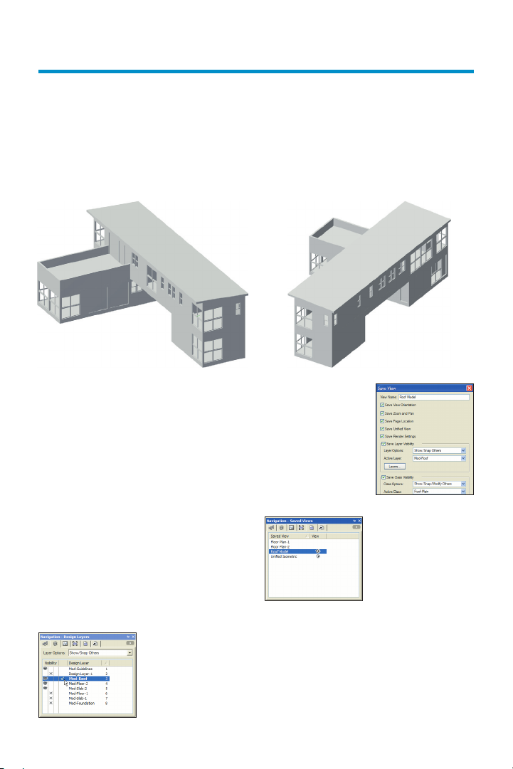
Exercise 8: Creating and
Modifying the Roof
In this exercise, you create a at roof object, and then you modify its conguration.
The completed exercise is shown in the following gure:
Saving a “Working” View
for the Roof
Next, you save a view to facilitate working
with the roof later in the development cycle.
1. If you did not complete Exercise 7—or
you are unsure of your le’s accuracy—
open the GS-VWAx07.vwx le.
2. In the Navigation palette:
• Select the Classes tab, and turn on
visibility of the Roof-Main class.
• Select the Design Layers tab, turn on
visibility of the Mod-Roof layer, and then
make it the active layer, as shown at left.
• Select the
Saved Views tab,
right-click the blank
area below the list
and select New.
56 | Vectorworks Architect 2011 Getting St arted Guide
In the Save View
dialog box, adjust
the View Name and
Active Class settings
as shown at right
and then click OK to
save the view.
• Notice that
the new view is
displayed in the list,
as shown at left.
• Double-click the Roof Model saved
view to activate it (in the View bar, notice
that Roof-Main is now the active class).
• Select the Design Layers tab and
make the Mod-Floor-2 layer active.
Page 59

Creating the Ceiling Slab
Next, you create an auto-bounded ceiling
slab object from the second oor’s exterior
walls.
3. From the Building Shell tool set, click the
Slab tool . In the Tool bar, make sure
that Picked Walls Mode is enabled,
and then select Ceiling from the Slab Style
drop-down list. Click the four exterior
second-oor walls, and then click Press to
Complete Operation
ceiling slab, as shown at top right. In the
Object Info palette, change the Slab object’s
Class property to Structural-Slab and its
Layer property to Mod-Roof to position its
elevation correctly. The slab is no longer
selected, as shown at bottom right.
to create the
Creating the Roof
Next, you create a slanted roof object from
the second oor’s exterior walls.
4. Press the X key, and then select any one
of the second oor’s four exterior walls.
From the menu, select Edit > Select
Connected Objects, and then conrm that
four walls are selected in the Object Info
palette. From the menu, select AEC >
Create Roof. In the Create Roof dialog box,
change settings as shown at left (click OK if
the message dialog box shown at right is
displayed).
Tip: In your own designs, you can specify either
a Rise:Run ratio (in inches), or angle value (in
degrees) for the Roof Pitch.
Vectorworks Architect 2011 Getting St arted Guide | 57
Page 60

5. Click OK to create the roof. Notice that
the Mod-Roof layer is now active and that
two objects are selected (the new ceiling
and roof objects). Press the X key twice to
clear the current selection, and then select
only the roof. The roof’s control points are
now displayed, as shown.
Creating Gabled Ends on
the Slanted Roof
Notice that Vectorworks created a hip roof
by default. Next, you modify the roof to
create the desired gabled ends and pitch.
6. Select the roof’s left control point, as
shown at left. In the Edit Roof Settings
dialog box, select the Gable option, and
then click OK to create the gabled end, as
shown at right. Repeat the process to
change the right side to a gable end.
7. Select the roof’s rear side control point
(near the left vertical balustrade wall). In the
Edit Roof Settings dialog box, select the
Gable option, change the Eave Overhang to
2'6", and then click OK to update the roof,
as shown below at top. Select the roof’s front
side control point (directly opposite the rear
side control point). In the Edit Roof Settings
dialog box, leave the Roof Edge Shape’s
Eave option selected, change the Pitch to
4.00°, change the Bearing Height to 0’6”
[Step test: Verify if this is reqd], change the
Eave Overhang to 1'0", and then click OK. In
the Object Info palette, disable the Create
Gable End Walls option to complete the
roof, as shown below at bottom.
58 | Vectorworks Architect 2011 Getting St arted Guide
Page 61

Next, you use the Fit Walls to Roof
command to extend the second oor’s
exterior walls to the roof bottom.
8. In the Navigation palette:
• Select the Saved Views tab and
activate the Unified Isometric saved view.
Press the X key, and then click in a blank
area of the drawing to clear the current
selection. Notice the slanted roof, as shown
at top right.
• Select the
Design Layers tab,
and then turn off
visibility of the
Mod-Roof roof
layer, as shown.
Hold down the Shift key and select the four
exterior walls, as shown at bottom right.
9. From the menu,
select AEC > Fit
Walls to Roof.
Enable the
Constrain Tops of
walls to 3D
geometry option,
and then select the Mod-Roof layer from the
drop-down list, as shown at right. Click OK
to complete the operation, as shown at left.
Vectorworks Architect 2011 Getting St arted Guide | 59
Page 62

Examining the
Completed Roof
Next, you examine the at roof in various
3D views.
10. In the Navigation palette, select the
Saved Views tab and activate the Unified
Isometric saved view. Press the X key, and
then click in a blank area of the drawing to
clear the current selection. From the View
bar, select OpenGL from the Current
Render Mode
to various standard 3D views, or use the
Flyover tool
pleted roof, as shown.
11. In the Navigation palette, activate the
Floor Plan-2 view. From the menu, select
View > Align Layer Views. In the Scripts
palette, double-click the Toggle Dimension
Class Visibility script to hide all dimen-
sions. Press Ctrl + 6 to adjust the display.
12.
Save the le.
If you set up your les as instructed in the
Checking Your Work section (p. 8), you
can now optionally check the accuracy of
your le.
13. Open the (read-only) GS-VWA xCheck.
vwx
le. In the Navigation palette,
double-click the 03 Roof Model saved view
to activate it, and then double-click the
Check EX08 saved view to activate it. Your
roof is displayed in green, and the master
le’s roof is displayed in its default color.
You should see your green roof overlaid
directly on top of the master le’s roof.
drop-down list. Switch
to examine the com-
14. After checking your le’s accuracy,
close the active le (your House.vwx le
should now be active). If your drawing is
inaccurate, close your le and continue with
the next exercise by starting with the
supplied le.
60 | Vectorworks Architect 2011 Getting St arted Guide
Page 63

Exercise 9: Editing
Architectural Elements
In this exercise, you edit various architectural elements to complete the basic house design.
The completed exercise is shown in the following gure:
Editing Windows
You start the exercise by simultaneously
modifying properties of all windows.
1. If you did not complete Exercise 8—or
you are unsure of your le’s accuracy—
open the GS-VWAx08.vwx le.
2. In the Navigation palette, activate the
Unified Isometric saved view. From the
Basic tools palette, click the Select Similar
tool
from the Active Settings drop-down list, and
then click any window. In the Object Info
palette:
• Verify 37 window objects are
selected.
• Change the Sash Operation to
Casement (wait a few seconds for the
windows to update after each change).
. In the Tool bar, select Object
• Scroll down and change the Sash
Width to 3” [76.20mm], and press Enter.
• Change the Sash Depth to 4”
[101.60mm], and then press Enter. Press the
X key twice, and notice that all windows
were modied, as shown.
Vectorworks Architect 2011 Getting St arted Guide | 61
Page 64

Creating a Corner Window
Next, you change properties of the two
smaller master bedroom windows to create
a corner window.
Notching the Second Floor’s
Floor Slab
Next, you notch the second oor’s oor slab
at the stairwell.
3. Hold down the
Shift key, and then
select the two
windows shown at
left. Press Ctrl + 6 to
zoom in, then scroll
down to the bottom
of the Object Info palette, and then:
• Enable the Corner Window option.
Notice that both windows automatically
move to the corner position.
• Select Mitered Sash from the Corner
Condition drop-down list, and examine the
mitered sash, as shown below at left.
• Select Corner Post from the Corner
Condition drop-down list, and change the
size to 5” [127.00mm]. Press Enter to update
the windows, and examine the corner post,
as shown in the next gure.
• Select Flush Glass from the Corner
Condition drop-down list, and then click in a
blank area to clear the selection. The completed corner window is shown below at right.
4. In the Navigation
palette, activate the
Floor Plan-2 view. In
the Scripts palette,
double-click the Toggle
Dimension Class Visibility script to hide
all dimensions. Press Ctrl + 6 to adjust the
display, and then zoom in on the area
shown above (notice the window sash width
and depth changes from step 2). Right-click
the oor to the left of the stairwell balustrade, and select Force Select. The
Mod-Slab-2 layer is automatically activated.
From the Basic palette, click Rectangle
and then enable Rectangle Mode
in the Tool bar. Draw a rectangle by
snapping to the point of the stair’s up arrow
and then snapping to the bottom ight’s up
line anywhere above the rst point,
approximately where shown.
62 | Vectorworks Architect 2011 Getting St arted Guide
Page 65

From the Basic tools palette, click Visibility
. In the Tool bar, click the Visibility for
Classes
and Invisible buttons to
enable them. Click the stair object to turn off
visibility of its class. Press 4 for the
Rectangle tool
shortcut, and then snap
to balustrade wall vertices to draw a second
rectangle, as shown below at left. Press the
X key and select the rst rectangle, and then
resize it by clicking its top right grip and
snapping to the inside wall corner (you can
optionally press the Z key to temporarily
zoom in), as shown below at right.
5. Shift + select the stairwell rectangle to
add it to the selection (two rectangles
should be selected), as shown at left.
Right-click the selection, and then select
Add Surface to combine both rectangles
into a single polygon, as shown at right.
6. Hold down the Shift key, and select the
oor object to add it to the current selection.
From the menu, select Modify > Clip
Surface
to clip the polygon from the oor
slab. Press the X key twice to clear the
current selection, and notice the oor’s
stairwell notch (shown at left). Click
Previous View
in the View bar to
display the stairs, as shown at right.
Note: The polygon is now part of the slab
object’s profile.
Vectorworks Architect 2011 Getting St arted Guide | 63
Page 66

Replacing Wall Styles
Next, you replace the generic (placeholder)
wall styles from Exercise 3 (p. 16) with
the nal styles.
7. Press Ctrl + 6 to adjust the display, and
then right-click any one of the second oor’s
four exterior walls (not the balustrade walls)
and select Force Select from the context
menu. From the menu, select Edit > Select
Connected Objects. In the Object Info
palette, conrm that four walls on the
Mod-Floor-2 layer are selected and then
select Replace from the Style drop-down
list. In the Wall Replacement dialog box,
select Ext-Wood-Flr-2, and then adjust
other settings as shown at left. Click OK to
replace the wall style. After several
seconds, all exterior walls are updated.
Clear the current selection so you can see
the new exterior wall style with additional
components, as shown at right.
8. Repeat the Select Connected Objects/
style replacement process for the three
balustrade walls. Select Ext-Wood-
Balustrade for the new style, and enable the
Replace Height option in the Wall Replace-
ment dialog box settings as shown, and then
click OK to complete the replacement.
64 | Vectorworks Architect 2011 Getting St arted Guide
Page 67

9. In the Navigation palette, activate the
Unified Isometric saved view. From the
Basic tools palette, click the Select Similar
tool
. In the Tool bar, select Class and
Object from the Active Settings drop-down
list, and then click any interior wall. In the
Object Info palette:
• Verify that 19 wall objects are selected.
• Select Replace from the Style
drop-down list, and then select Int-Gypsum
Bd for the new style, and specify the
remainder of the Wall Replacement dialog
box settings the same as you did for step 7.
Click OK to complete the replacement.
10. In the Navigation palette, activate the
Floor Plan-1 saved view. With the Select
Similar tool still active, click one of the
exterior walls. In the Object Info palette:
• Verify that ten wall objects are selected.
• Select Replace from the Style
drop-down list, and then select Ext-Wood-
Flr-1 for the new style, and specify the
remainder of the Wall Replacement dialog
box settings the same as you did for step 8.
Click OK to complete the replacement.
Press the X key twice to clear the current
selection, and then zoom in on the stairwell/
pantry area shown at left. Notice the new
wall style components, as shown at right.
Notes:
1) It’s not necessary for this exercise, but you
can optionally use the Wall Join tool with T
Join Mode to re-create any incorrectly
displayed component intersections on both
floors.
2) To save time in this tutorial, you replaced
the placeholder wall styles with styles that have a
compatible overall thickness. When you replace
wall styles with different sized components in
your own designs, you can align edges of various
wall components (or the entire wall) as required.
Creating Wall End Caps
Next, you create wall end caps for the
stairwell wall and pantry wall.
11. From the, click Wall End Cap .
From the Tool bar, enable Component
Wrap Mode
Cap Preferences
Cap preferences dialog box, make sure the
Extend Cap Past Wall Endpoint option is
disabled (because this design is based on
overall wall thicknesses), and then click
OK. Click in the middle of the stairwell
wall’s gray gypsum components close to
the wall cap (but do not click the edges) to
create the wall end cap which wraps them
continuously around
the end as shown. If
your end cap does
not match the gure,
undo the wall end
cap, and then zoom
in and try again.
, and then click Wall End
. In the Wall End
Vectorworks Architect 2011 Getting St arted Guide | 65
Page 68

Next, you draw a rectangle, and then you
use the Wall End Cap tool’s Add Mode to
join the rectangle to the pantry wall's core
so that it extends to the exterior wall's core.
You use the Wall End Cap tool because the
Wall Join tool can’t join these components
in this particular conguration.
12. Zoom out, and then zoom in on the
corner where the pantry wall meets the
exterior walls, as shown at left. Press 4 for
the Rectangle tool shortcut, and then snap
to endpoints to draw a rectangle between
the pantry wall’s core and the exterior wall’s
core, as shown at right.
13. From the Building Shell tool set, click
Wall End Cap
Mode
, and then enable Add
in the Tool bar. Click the middle
of the pantry wall
core (near its top
edge), and then click
inside the rectangle.
The area of the
rectangle is added
to the core, as
shown at left.
Press the X key, and then select the pantry
wall below the end cap. Notice that the start
point is now at the end of the wall cap, as
shown below at left. Select only the wall end
cap near its top edge. In the Object Info
Palette, enable the Extend Cap Past Wall
Endpoint option to complete the end cap.
Select only the pantry wall and notice that
the start point is now correctly at the edge of
the exterior wall, as shown at right.
Note: The Wall End Cap tool’s Clip Mode
can’t clip the exterior horizontal wall’s gypsum
component because of the joined end. If it wasn’t
a joined end, you would clip the rectangle from
the exterior wall’s gypsum component before you
add it to the pantry wall’s core component. In this
particular case you could break the corner L- join,
but it would alter the shape of the auto-bounded
slab associated with these walls.
Now that all wall and slab components are
in their nal congurations for accurate data
extraction purposes (not covered in this
tutorial), you hide component details for
drawing clarity.
66 | Vectorworks Architect 2011 Getting St arted Guide
Page 69

14. Press the X key twice to clear the
current selection, and then press Ctrl + 6 to
adjust the display. On the far right side of
the Tool bar, enable the Hide Details
quick pref. All individual wall components
are now hidden, as shown at right.
Replacing Slab Styles
Next, you replace the generic (placeholder)
oor slab styles from Exercise 6 (p. 34) and
Exercise 7
15. In the Navigation palette, activate the
Unified Isometric saved view. Press the X
key twice, and then hold down the Shift key,
and select both oor slabs on the
Mod-Slab-1 layer. In the Object Info palette,
select Replace from the Style drop-down
list. In the Slab Replacement dialog box,
select Ground-Hardwood, and adjust
other settings as shown at left, and then
click OK to replace the slab style. Clear the
current selection so you can see the new
slab style with additional components, as
shown at right.
(p. 48) with the nal styles.
16. Repeat the Shift + select and replace-
ment process for the second oor’s oor
slabs (select the Mechanical-Duct Gap
slab style, and enable only the Replace
Height option in the Slab Replacement
dialog box). Clear the current selection so
you can see the new slab style with
additional components, as shown.
Vectorworks Architect 2011 Getting St arted Guide | 67
Page 70

Note: The auto-boundary edge settings for the
final slab styles’ components automatically adjust
wall component heights and/or slab component
widths to create and maintain accurate junctions
where walls meet floor and ceiling slab objects.
You will see these junctions clearly after you
complete the "Creating a section viewport" section
(p. 72) and "Editing section viewport display
properties" section (p. 74) in Exercise 10.
17. Use 3D view controls and OpenGL
render mode to examine the model (as
shown). In the Navigation palette, activate
the Floor Plan-1 saved view. From the
menu, select View > Align Layer Views.
Press Ctrl + 6 to adjust the display.
18.
Save the le.
If you set up your les as instructed in the
Checking Your Work section (p. 8), you
can now optionally check the accuracy of
your le.
19. Open the (read-only) GS-VWAxCheck.
vwx
le. In the Navigation palette,
double-click the 01 Floor Plan-1 saved view
to activate it, and then double-click the
Check EX09 saved view to activate it.
20. Use the Zoom
and Pan
tools (in the Basic tools palette), and the
Previous View tool
(in the View bar) as
necessary to examine the drawing. Your
drawing objects are displayed in red, and the
master le’s drawing objects are displayed in
their default colors. You should see your red
drawing objects overlaid directly on top of
the master le’s drawing objects.
21. In the Navigation palette, double-click
the 02 Floor Plan-2 saved view to activate it,
and then double-click the Check EX09
saved view to activate it.
22. Use the Zoom
and Pan tools
(in the Basic tools palette) and the Previous
View tool
(in the View bar) as necessary
to examine the drawing. Your drawing objects
are displayed in blue, and the master le’s
drawing objects are displayed in their default
colors. You should see your blue drawing
objects overlaid directly on top of the master
le’s drawing objects.
23. After checking your le’s accuracy, close
the active le (your House.vwx le should
now be active). If your drawing is inaccurate,
close your le and continue with the next
exercise by starting with the supplied le.
68 | Vectorworks Architect 2011 Getting St arted Guide
Page 71

Section 5: Creating
Construction Documents
In two exercises, this section covers the following processes in the construction documentation stage of the home design project:
•
Creating Floor and Roof Plans (p. 70)
• Creating Elevations (p. 71)
• Creating a Section Viewport (p. 72)
• Editing Section Viewport Display Properties (p. 74)
• Inserting Appliance Symbols (p. 75)
• Inserting Kitchen Symbols (p. 76)
•
Inserting Plumbing Fixture Symbols (p. 77)
• Creating Dimensions (p. 81)
• Adjusting Dimension Visibility in Multiple Viewports and Saved Views (p. 82)
• Saving Batch Export PDF Sets (p. 84)
•
Exporting a Saved Set to a PDF File (p. 85)
In these exercises, you use a variety of 2D and 3D tools to create basic versions of
commonly used construction documents from viewports (that display objects on multiple
design layers) on sheet layers.
create corresponding architectural and annotation objects as required. After completing the
drawings, you save batch export PDF sets, and then you export a saved set to a PDF le.
For some documents, you also work with external les or
Note: Depending on the type of construction document, you create annotations in design layers or
directly inside the viewport (in viewport annotation mode) based on suggested best practices.
Vectorworks Architect 2011 Getting St arted Guide | 69
Page 72

Exercise 10: Generating
Construction Drawings
In this exercise, you complete the initial setup steps of commonly used construction
drawings by arranging and modifying viewports to display your model. The completed
exercise is shown in the following gure:
Note: To save time, you skip the process of
creating fully detailed construction documents.
Creating Floor and
Roof Plans
You start by activating the oor and roof
plan sheets and arrange or modify the
viewports as necessary.
1. If you did not complete Exercise 9—or
you are unsure of your le’s accuracy—
open the GS-VWAx09.v wx le.
2. In the Navigation palette, activate the
Sheet-Floor Plan-1 sheet layer, and then
clear the current selection (if anything is
selected). Press Ctrl + 6, and notice that the
viewport is not centered, as shown at left.
Drag any object in the oor plan to reposition
the viewport in the approximate center of the
drawing sheet, as shown at right.
Note: For illustration clarity, all pre-configured
sheet layer viewports in this file have their Show
Wall Components advanced property option
70 | Vectorworks Architect 2011 Getting St arted Guide
disabled. These sheet layers and viewports were
created with the Create Standard Viewports
command, which enables this option by default.
Page 73

3. Repeat the
process for the
Sheet-Floor Plan-2
sheet layer. In the
Navigation palette,
activate the
Sheet-Roof Plan
sheet layer. Select
only the viewport, and then click Layers in
the Object Info palette. In the Viewport
Layer Properties dialog box, turn on visibility
of the Mod-Floor-2 layer (shown at left) and
then click OK. Reposition the viewport
approximately where shown at top right.
Creating Elevations
Next, you adjust the viewport in the
Sheet-Elevations-1 sheet layer to show the
front elevation. You then copy the viewport
to create the rear elevation.
4. Activate the Sheet-Elevations-1 sheet
layer. Select only the viewport, and then in
the Object Info palette:
• Disable the Display Planar Objects
option.
• Click Classes. Hold down the Alt key,
and click in the rst column to turn on
visibility of all classes, and then click OK.
• Change the View to Front.
• Change Background Render to
Hidden Line. Notice the striped highlighting
around the viewport (indicating that it needs
to be updated).
Reposition the viewport, as shown.
5. Start dragging the viewport straight up,
and then hold down the Shift and Ctrl keys
to create a copy, as shown at left. For the
new viewport, change the View to Back, as
shown at right.
Vectorworks Architect 2011 Getting St arted Guide | 71
Page 74

6. Shift + select the front elevation viewport.
In the Object Info palette, verify that two
Viewports are selected, and then click
Update to hide the lines. Click in a blank
area of the drawing to clear the selection
and examine the elevations, as shown.
Note: In your own designs, you would repeat this
process to create right and left elevation
viewports on other sheets as necessar y. To save
time in this exercise, you skip the repetitive
process of creating additional elevation viewports.
Creating a Section Viewport
Next you create a live section viewport of
the house.
7. In the Navigation palette, select the
Viewports tab, and then double-click the
VP-Floor Plan-1 viewport to select it (and
activate the Sheet-Floor Plan-1 sheet layer).
With the viewport still selected, select View
> Create Section Viewport from the menu.
To dene the section line, click point 1, and
then hold down the Shift key (the preview
line should be just inside the exterior wall)
and click point 2, where shown at top left.
Move the cursor to see how to control the
view direction, and then double-click below
the line (when the view direction arrow
points down), as shown at middle. Notice
that the section marker is created (shown at
bottom left),
72 | Vectorworks Architect 2011 Getting St arted Guide
8. In the Create Section Viewport dialog
box:
• Disable the Name Viewport as Dwg
No./Sheet No. option.
Page 75

• Adjust other
eld values, as shown
at left.
• Click Layers,
and adjust visibilities
as shown in the next
gure, and then click
OK.
• Click Classes,
and turn on visibility of
the Roof-Main class,
and then click OK.
• Click
Advanced Section
Properties. In the
Extent tab, select
Infinite for the Length
Range, Depth Range,
and Height Range.
Select the Attributes tab, and select the
Separate Cross Sections option, enable
the Use Attributes of Original Objects
option, and then verify or adjust other
settings as shown above at right. Select the
Display tab, and disable the Cast Shadows
of Objects Removed
by Section option,
enable the Show
Wall and Slab
Components option,
and then click OK
twice. After several
seconds, the
viewport—with
drawing label—is
created, the
Sheet-Sections-1 sheet layer is activated
(identied in the view bar as A4.1 [Sheet-
Sections-1]), and the viewport is placed in
the center of the sheet by default. Click in a
blank area to clear the selection, and then
select and delete the non-section viewport.
Drag the section viewport into position,
approximately where shown below.
Notes:
1) The existing viewport was created when the
Create Standard Viewports command was used
to set up this file.
2) To optionally fix the ceiling/wall junction, edit
the Ceiling slab definition and set the Rafters’ Auto-
Bound edge offest to Inner face of wall core.
3) The drawing label automatically picked up
the sheet number because automatic drawing
coordination is enabled.
4) To optionally fix the drawing label length,
right-click the drawing label and select Edit
Annotations. Select the drawing label, and then
in the Object Info palette, select Auto-Fit from the
Line Length Mode drop-down list. Click the
orange Exit Viewport Annotation button (in the
upper right corner of the drawing area) to return to
the sheet layer.
Vectorworks Architect 2011 Getting St arted Guide | 73
Page 76

Editing Section Viewport
Display Properties
Next, you add depth to the section by
changing the section viewport’s Projection
setting and then you change the viewport
properties to improve legibility.
9. In the Object Info palette, select Oblique
Cabinet 30 from the Projection drop-down
list, and then click Update to incorporate
the change. Press Ctrl + 6 to see the
completed section viewport, as shown
(leave the section viewport selected for the
next step).
Tip: You can also create offset section sheet
layer viewports (but you cannot change their
projection). If you create an offset design layer
section viewport, you can set up any 3D view or
projection in the design layer and display the
design layer section viewport in a sheet layer
viewport. For step-by-step instructions for
creating an offset section design layer viewport
from the Architect Getting Started website, see
www.nemetschek.net/training/2011/architect-
2011-getting-started-guide.php.
10. In the Object Info
palette, scroll down
and click Section
Line Instances. In the
Section Line
Instances dialog box,
select the Viewports
tab, and then select
the VP-Floor Plan-1
viewport, as shown at
to right (the check
mark identies a
section line instance).
Then click Activate. Viewport annotation
mode for the VP-Floor Plan-1 viewport is
automatically activated, and the section line
is object selected. Press Ctrl + 6 to see both
section line markers. In the Attributes palette,
select Solid for both the Fill Style and Pen
Style, and then select black for the Solid Fill
Color, as shown at bottom right. In the Object
Info palette, select Dwg No. over Sheet No.
from the Text Style drop-down list (see Tip
below gure). Click the orange Exit Viewport
Annotation button (in the upper right corner
of the drawing area), and then press Ctrl + 6
to adjust the display. Examine the completed
section line, as shown below.
Next, you navigate back to the section line
instance from the section viewport, and then
you adjust section line properties.
74 | Vectorworks Architect 2011 Getting St arted Guide
Page 77
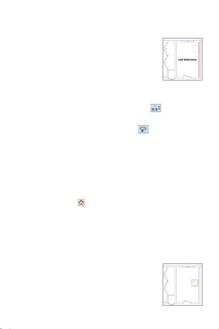
Tip: It’s not necessary for this exercise, but you
can optionally change the ending marker to
match the beginning marker. To do this, click
Section Marker Style(s) in the Object Info
palette. In the Set Marker Style(s) dialog box,
select Match Beginning and then click OK.
Inserting Appliance Symbols
Next, you insert appliance symbols in the
upstairs hall bathroom. You can choose to
optionally follow steps 11 through 19, where
you insert various symbols and plug-in
objects in both oor plans. Or to save time,
you can close your le and open the
GS-V WA x10-Step20.v wx le (with the
symbols and plug-in objects already inserted)
and skip ahead to step 20 (p. 79).
11. Open the Equip-Residential Appliances-Imp.vwx
this le open through step 18—don’t close
your house le—see Note below). In the
Resource Browser, click Home to activate
the Equip-Residential Appliances-Imp
Note: This file is also included with Vectorworks
Architect in the following folder:
[Vectorworks application folder]\Libraries\
Objects-Building Architecture & Interior
12. From the Window menu, select your
house le to activate it. In the Navigation
palette, activate the Floor Plan-2 saved view.
In the Scripts palette, double-click the Toggle
Dimension Class Visibility script to hide all
dimensions. Press Ctrl + 6, and then zoom in
on the hall bathroom. In the Resource
le in the Data Set folder (keep
le.
Browser, notice that
the Equip-Residen-
tial Appliances-Imp
le is still active, and
then open the
Symbols/Plug-in
Objects folder (if it’s
not already open). Double-click the
Clothes_Washer_Top symbol to activate the
Symbol Insertion
tool. In the Tool bar,
enable Wall Insertion Mode (if it’s not
already enabled) and Align Actual Insertion
Point Mode
, and then move your
cursor—with phantom preview—over the
wall, approximately where shown at left.
Double-click to complete the insertion, as
shown at center. In the Object Info palette:
• Make sure that Symbol in Wall is dis-
played (or undo the placement and try
again).
• Select Left Edge from the Insert
drop-down list.
• Select No Break from the Break
drop-down list.
• Click Set Position, and then for the
reference point, snap to the wall’s top left
inside corner. For the object point, snap to
either corner on the top edge of the clothes
washer. In the Enter Offset dialog box, specify
an offset of 3’10” [1.168m], and then click OK
to move it into its nal
position, where
shown. See Symbol
Insertion Notes (after
step 18) for additional
information.
Vectorworks Architect 2011 Getting St arted Guide | 75
Page 78

13. Press the X key twice to clear the current
selection, and repeat the previous step to
insert the Clothes_Dryer_Sm symbol with
an offset of 2” [50.80mm] between the
clothes washer (as shown), and then press
the X key twice to clear the selection.
Inserting Kitchen Symbols
Next, you insert various symbols and plug-in
objects (with minimal instruction) to
complete the kitchen.
14. In the Navigation palette, activate the
Floor Plan-1 saved view. In the Scripts
palette, double-click the Toggle Dimension
Class Visibility script to hide all dimen-
sions. Press Ctrl + 6, and then zoom in on
the kitchen area. Insert kitchen symbols in
the order listed below. To do this, note the
source VWX le of the symbol, and then if
the symbol is located in:
• You r House.v w x le: Double-click the
symbol in your House.vwx le’s Resource
Browser and insert it where shown at right
(and also shown in p. 77 below the table in a
bird’s-eye perspective view for clarity).
• Another le: Open the VWX File
specied (in the Data Set folder—see Note
below lower gure; keep VWX les open
through step 18), and then switch the focus
back to the house le. In the Resource
Browser, activate the VWX File you just
opened (if necessary, open the symbol
folder, and scroll down), and then double-
click the symbol and insert it where shown.
See Symbol Insertion Notes (after step 18)
for additional instructions. Use the Move by
Points tool
Note: The Equip-Residential Appliances
SubZero USA.vwx file is also included with
Vectorworks Architect in the following folder:
[Vectorworks application folder]\Libraries\
Objects-Building Architecture & Interior.
as necessary.
76 | Vectorworks Architect 2011 Getting St arted Guide
Page 79
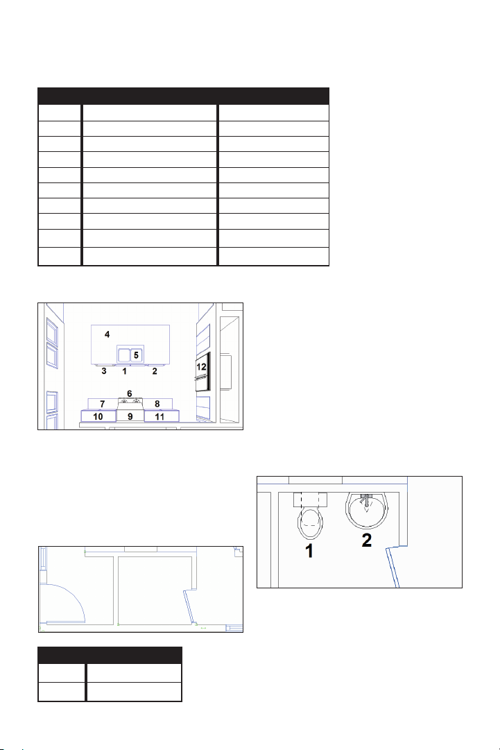
Order Source VWX File Symbol or Folder > Symbol
1 House 2CompSinkCabinet
2 House IslandCornerCabinet
3 Equip-Residential Appliances-Imp Dishwasher
4 House IslandCountertop
5 House 2CompSink
6 Equip-Residential Appliances-Imp Range_30_Gas
7,8 House *RangeBaseCabinet
9 Equip-Residential Appliances-Imp Range Hood 30
10,11 House RangeWallCabinet
12 Equip-Residential Appliances SubZero USA Built-in Refrigeration > **642 Stainless
15. Zoom in on the bathroom as shown.
16. Open the Sanitary-Fixtures.vwx
the Data Set folder. In the Resource
Browser, activate the Sanitary-Fixtures.
vwx
le (scroll down as necessary), and
then double-click symbols in the order listed
in the table below at left and place them in
the bathroom where shown. See Symbol
Insertion Notes (after step 18),
Inserting Plumbing
Fixture Symbols
Next, you insert plumbing xture symbols
(with minimal instruction) in the rst and
second oor plans.
*After you insert item 7,
use the Mirror tool with
Duplicate and Mirror
Mode enabled to create
item 8.
**Insert this symbol in the
center of the pantry wall
and then in the Object Info
palette; change the Class
to None, and select Full
break with caps from the
Break drop-down list.
le in
Order Symbol
1 WC Wall Floor Tank
2 Lav Pedestal
Note: The Sanitary-Fixtures.vwx file is also
included with Vectorworks Architect in the
following folder: [Vectorworks application
folder]\Libraries\Objects-Building Services.
Vectorworks Architect 2011 Getting St arted Guide | 77
Page 80

17. In the Navigation palette, activate the
Floor Plan-2 saved view. In the Scripts
palette, double-click the Toggle Dimension
Class Visibility script to hide all dimen-
sions, and then press Ctrl + 6, and zoom in
on the area shown below.
Symbol Insertion Notes:
1) You can drag symbols out of the Resource
Browser and drop them into the drawing, but you
double-click them to make them active so you
can use the cursor’s phantom preview to facilitate
accurate placement.
2) Make sure Wall Insertion Mode is
active when inserting symbols. You don’t have to
insert symbols in walls, but if you do, the symbols
will move along with the walls when you drag wall
segments to move or resize them.
3 Use Insert = Left edge (or Right edge),
and Break = No break options as required.
18. Insert symbols and plug-in objects in
the order listed in the table below and place
them in the bathrooms where shown below.
See Symbol Insertion Notes for additional
instructions.
Order Source VWX File Symbol
1, 2 Sanitary-Fixtures WC Wall Floor Tank
3, 4 House VanitySink
5 House Shower
6, 7 House Bathtub
4) Click the Selection Tool to terminate the
Symbol Insertion tool after each symbol
insertion, and then drag symbols and/or use the
Flip and Set Position controls as necessary to
orient and move them into their correct position.
You can also use temporary associative
dimensions to position symbols.
5) In some cases, you
may have to insert the
symbol in another location
away from other symbols,
and then drag and snap
it—or use the Set Position
control—to move it into its
correct position.
6) When correctly
inserted, all symbols should
display the “In Wall” suffix
after the symbol name in the
Object Info palette.
78 | Vectorworks Architect 2011 Getting St arted Guide
Page 81

19. Close all three symbol les.
20. If you skipped steps 11 through 19,
open the GS-VWAx10 -Step20.vwx
le. In
the Navigation palette, select the Viewports
tab, and then double-click the Section 1
viewport to activate it. Press Ctrl + 6 to
zoom in on the selected viewport. With the
viewport still selected, click Update in the
Object Info palette. Press the X key, and
then click in a blank area to clear the
selection. Notice that the viewport updated
with the appliance, kitchen, and plumbing
xture symbols, as shown.
Note: You can move the section line if the
sectioned bathtubs outside walls block the view
inside both bathtubs, or if you want to examine
the model at a different section point. To do this,
right-click the VP-Floor Plan-1 viewport and
select Edit Annotations, and then press the X
key and drag the section line to move it. With the
section line selected, click Navigate to Section
Viewport in the Object Info palette, and then
press Ctrl + 6 to adjust the display. Click Update
in the Object Info palette to see the change.
21. Save the file.
Vectorworks Architect 2011 Getting St arted Guide | 79
Page 82

If you set up your files as instructed in the
Checking Your Work section (p. 8), you
can now optionally check the accuracy of your
file.
Note: The methods used in the GS-VWAx-
Check.vwx file to compare your drawing file with
the master files cannot compare viewports. You
must manually check the accuracy of all of your
viewports and any objects you created in
viewport annotation editing mode.
22. Open the (read-only) GS-V WAxCheck.
vwx
le. In the Navigation palette, double-
click the 01 Floor Plan-1 saved view to
activate it, and then double-click the Check
EX10 saved view to activate it.
23. Use the Zoom
and Pan tools
(in the Basic tools palette), and the Previous
View tool
(in the View bar) as necessary
to examine the drawing. Your drawing objects
are displayed in red, and the master le’s
drawing objects are displayed in their default
colors. You should see your red drawing
objects overlaid directly on top of the master
le’s drawing objects.
24. In the Navigation palette, double-click
the 02 Floor Plan-2 saved view to activate it,
and then double-click the Ch eck EX10 saved
view to activate it.
25. Use the Zoom
and Pan tools
(in the Basic tools palette) and the Previous
View tool
(in the View bar) as necessary
to examine the drawing. Your drawing
objects are displayed in blue, and the
master le’s drawing objects are displayed
in their default colors. You should see your
blue drawing objects overlaid directly on top
of the master le’s drawing objects.
26. After checking your le’s accuracy,
close the active le (your House.vwx le
should now be active). If your drawing is
inaccurate, close your le and continue with
the next exercise by starting with the
supplied le.
80 | Vectorworks Architect 2011 Getting St arted Guide
Page 83

Exercise 11: Adding Annotations
In this exercise, you complete the rst and second oor plans by adding dimensions, and
then you simultaneously adjust dimension visibility in a viewport and saved view. The
completed exercise is shown in the following gure:
Creating Dimensions
You start the exercise by creating linear and
chain dimensions for architectural objects
on both oors.
1. If you did not complete Exercise 10—or
you are unsure of your le’s accuracy—
open the GS-VWAx10.vwx le.
2. Activate the Floor Plan-1 saved view,
and then press Ctrl + 6 to adjust the display.
Use the Constrained Linear Dimension
tool
Mode
remaining associative dimensions,
approximately where shown at right.
Activate the Floor Plan-2 saved view, and
then repeat the process to create the
remaining associative dimensions,
approximately where shown at bottom right.
with either Constrained Chain
or Constrained Linear Mode
(see Notes) as necessary to create the
Vectorworks Architect 2011 Getting St arted Guide | 81
Page 84

Notes:
1) Click window and door insertion points (the
plug-in object will pre-highlight to confirm the
insertion point will be selected) to create
associative linear and chain dimensions. It’s not
necessary for this exercise, but you can optionally
change dimension length values as desired.
2) You can unlock existing dimensions and
reposition the dimension or text (by dragging), as
necessary. See also Notes on p. 27.
3) If you haven’t created specific dimensional
relationships (optional in previous exercises), you
can alternately run the Custom Select All Dims
script, and then press the Delete key to remove
all dimensions from the drawing. You can then
run the Dimension Exterior Walls command to
re-create all dimensions on both floors. To
automatically associate dimensions with T-joined
wall intersections with the Dimension Exterior
Walls command, select Centerlines from the
Dimension to Wall drop-down list. Then select
Center of Openings from the Dimension
drop-down list in the Dimension Exterior Walls
dialog box.
4) Refer to Exercise 13 in the “Getting Started
with Vectorworks Fundamentals” guide for an
overview of creating a text block and a callout
3. In the Navigation palette, select the
Classes tab, and then right-click the
Dimension class and select Visibilities.
The Organization dialog box is displayed
with the Dimension class selected (in Visibilities mode). Resize the Organization dialog
box (if necessary) so you can see the entire
list of viewports and saved views. The
Dimension class is visible by default in all
saved views and viewports automatically
created with the Create Standard
Viewports command (but not the two saved
views that you created), as shown.
4. Turn off visibility for the VP-Roof Plan
viewport, and then turn on visibility for the
Roof Model saved view, as shown. Click OK
to close the Organization dialog box and
save the changes.
Adjusting Dimension Visibility
in Multiple Viewports and
Saved Views
Next, you use the Organization dialog box to
simultaneously adjust visibilities in a
viewport and saved view to hide or show
dimension objects.
82 | Vectorworks Architect 2011 Getting St arted Guide
5.
Examine the changes in the oor plan
sheet layers, and then save the le.
Page 85

If you set up your les as instructed in the
Checking Your Work section (p. 8), you
can now optionally check the accuracy of
your le.
6. Open the (read-only) GS-VWAxCheck.
vwx
le. In the Navigation palette,
double-click the 01 Floor Plan-1 saved view
to activate it, and then double-click the
Check E X11 saved view to activate it.
7. Use the Use the Zoom
and Pan
tools (in the Basic tools palette), and
the Previous View tool (in the View bar)
as necessary to examine the drawing. Your
drawing objects are displayed in red, and
the master le’s drawing objects are
displayed in their default colors. You should
see your red drawing objects overlaid
directly on top of the master le’s drawing
objects.
8. In the Navigation palette, double-click
the 02 Floor Plan-2 saved view to activate
it, and then double-click the Chec k EX11
saved view to activate it.
9. Use the Use the Zoom
and Pan
tools (in the Basic tools palette), and
the Previous View tool (in the View bar)
as necessary to examine the drawing. Your
drawing objects are displayed in blue, and
the master le’s drawing objects are
displayed in their default colors. You should
see your blue drawing objects overlaid
directly on top of the master le’s drawing
objects.
10.
After checking your le’s accuracy,
close the active le (your House.vwx le
should now be active).
Vectorworks Architect 2011 Getting St arted Guide | 83
Page 86

Exercise 12: Printing
Construction Drawings
In this exercise, you save a batch of export PDF sets, and then export one of the saved sets
to a PDF le.
Saving Batch Export
PDF Sets
You start the exercise by saving a batch
export PDF set of oor plans from various
sheet layers in multiple drawing les.
1. If you did not set up your les as
instructed in the Checking Your Work
section (p. 8), copy the Data Set folder
on the DVD to any location on your hard
disk. Open the G S -V WAx11.v w x
the Data Set folder on your hard disk, and
then save the le under the name GSVWAx12.vwx in the same folder.
2. From the menu, select File > Export >
Export PDF (Batch). In the Batch Export
PDF dialog box:
• Drag the lower right corner to
increase the dialog box’s height and width,
and then move it as high up on the screen
as possible.
• Notice the available sheets and saved
views from the <Active File> on the left side.
• Double-click the right edge of the
Name column’s header to t the column
width to the text, as shown.
• Click Select Folder, and navigate
to the Data Set folder on your hard disk.
le from
Click the Data Set folder name to open it,
and then click the Batch Export folder.
Click OK to add the sheets and saved views
from les in the Batch Export folder to the
available list.
3. Hold down the Ctrl key, and select the
following sheets. Then click the > arrow to
move them to the Sheets and Saved Views
to Export list, as shown:
• <Active File>: A2.1 [Sheet-Floor
Plan -1]
• <Active File>: A2.2 [Sheet-Floor
Plan-2]
• GS-VWA_BE1.vw x: A1.1 [First
Floor Plan]
• GS-VWA_BE1.vw x: A1.2 [Second
Floor Plan]
• GS-V WA _ BE2.vwx: A1.1 [First
Floor Plan]
• GS-V WA _ BE2.vwx: A1.2 [Second
Floor Plan]
84 | Vectorworks Architect 2011 Getting St arted Guide
Page 87

In the Sheets and Saved Views to Export list,
double-click the right edge of the Name and
File Name column headers, and then drag
the number in the # column of various sheets
as required to reorder them as shown.
4. Click Save a Set.
In the New Saved
Set dialog box,
change the name to
Floor Plans, and select the Path relative
to the active document option, as shown,
and then click OK to save the new set.
Leave the Batch Export PDF dialog box
open for the next step.
Next, you save a batch export PDF set of
presentation drawings.
5. Click the << arrow to clear the Sheets
and Saved Views to Export list. Repeat the
selection/move/column resize/reorder
process to populate the Sheets and Saved
Views to Export list as shown.
6. Click Save a Set.
In the New Saved
Set dialog box,
change the name to
Presentations, select the Path relative to
the active document option, and then click
OK to save the new set.
Vectorworks Architect 2011 Getting St arted Guide | 85
Page 88

Exporting a Saved Set to
a PDF File
Next, you export the Floor Plans set saved
to a PDF le.
7. Click Manage Sets. In the Manage Saved
Sets dialog box, select the Floor Plans
saved set, and then click Recall. The
Manage Saved Sets dialog box is automatically closed, and only the sheets from the
Floor Plans saved set are now displayed in
the right side of the Batch Export dialog box,
as shown.
8. Make sure that the Export as separate
les option is disabled, and then click
Export. In the Export PDF dialog box, adjust
settings as shown, and then click Export. In
the Export as PDF Document dialog box,
navigate to the Batch Export folder, and then
change the default (active VWX) le name to
Floor Plans.pdf. Click Save to create the
PDF le. After several seconds, the PDF le
is created and opened in your default PDF
viewer. Examine the multi-sheet PDF le,
and then close your viewer when nished.
9. Congratulations! You have now
completed the tutorial!
86 | Vectorworks Architect 2011 Getting St arted Guide
 Loading...