

Page 1
36
Catalog data relates to an ambient temperature of +25°C measured at 125 Hz, 0.5V RMS unless otherwise specified.
Substitutions of higher voltage ratings, lower ESR values, tighter capacitance tolerances and higher temperature rated devices
will increase performance and reliability.
Advantages of tantalum capacitors are:
• High volumetric efficiency.
• Stable electrical performance over temperature (T.C. 12%).
• Operating temperature range –55°C to +125°C, 2/3 Vr (linear derating) above +85°C, CGT series is derated above +40°C.
• Better frequency characteristics than aluminum electrolytics.
• Self-Healing, no wear out mechanism. No degradation in performance or reliability.
• No limitation on shelf life.
Surge voltages may be applied up to ten times in an hour for periods up to 30 seconds at a time. They are not intended for
continuous operation and should not be used as a parameter for design. See table below.
Voltage derating improves the operating reliability of a tantalum capacitor. Select a higher voltage rated part (30% to 70%)
than the maximum line voltage. In the case of low impedance circuits, the tantalum capacitor is likely to be stressed by current
surges. In circuits which undergo rapid charge/discharge, a protective resistor of 1.0 ohm per applied volt is recommended. If
this is impossible, a voltage-derating factor of up to 70% is recommended. A combination of tantalum capacitors can be
connected in series to increase working voltage of the equivalent capacitor. In many power supply topologies where the di/dt
through the capacitor is limited, such as most implementations of buck (current mode), forward converter and flyback, the
requirement for series resistance is decreased to 0.1 ohm per applied volt. This level of resistance is used as a basis for the series
resistance variable in a 1%/1000 hours 60% confidence level reference. This is what steady state life tests are based on. Certain
test circuits such as ICT are likely to subject the capacitor to large voltage and current transients, which will not be seen in
normal use. This should be taken into account when considering the capacitors rated voltage.
A small amount of reverse voltage is permissible for short periods. It is not intended to cover continuous operation.
Maximum reverse voltages are:
+25°C 10% of rated voltage not exceeding 1.0 volt
+85°C 3% of rated voltage not exceeding 0.5 volt
+125°C 1% of rated voltage not exceeding 0.1 volt
Tantalum capacitors are polar devices. A non-polar effect can be created by connecting two devices, arranged back-to-back (to -). The capacitance value of each part should be twice the required capacitance value, equal tolerance and rated voltage. For
example, two PCT10/35DK devices connected in a back-to-back configuration would result in a non-polar 5ufd, 35volt device.
In DC-DC converters, the input side is typically fed from voltage sources, which are not regulated and are of nominally low impedance. This type of application severely stresses the capacitor. A higher than normal failure rate level may be experienced.
Maximum voltage derating and use of low ESR devices is recommended.
Higher capacitances and even lower ESR
Values can be achieved by connecting tantalum capacitors in parallel.
Electrostatic Discharge
Tantalum capacitors demonstrate no sensitivity to ESD.
Flammability UL Rating UL94 VO, Oxygen Index 35%. Epoxy, Hysol MG 33.
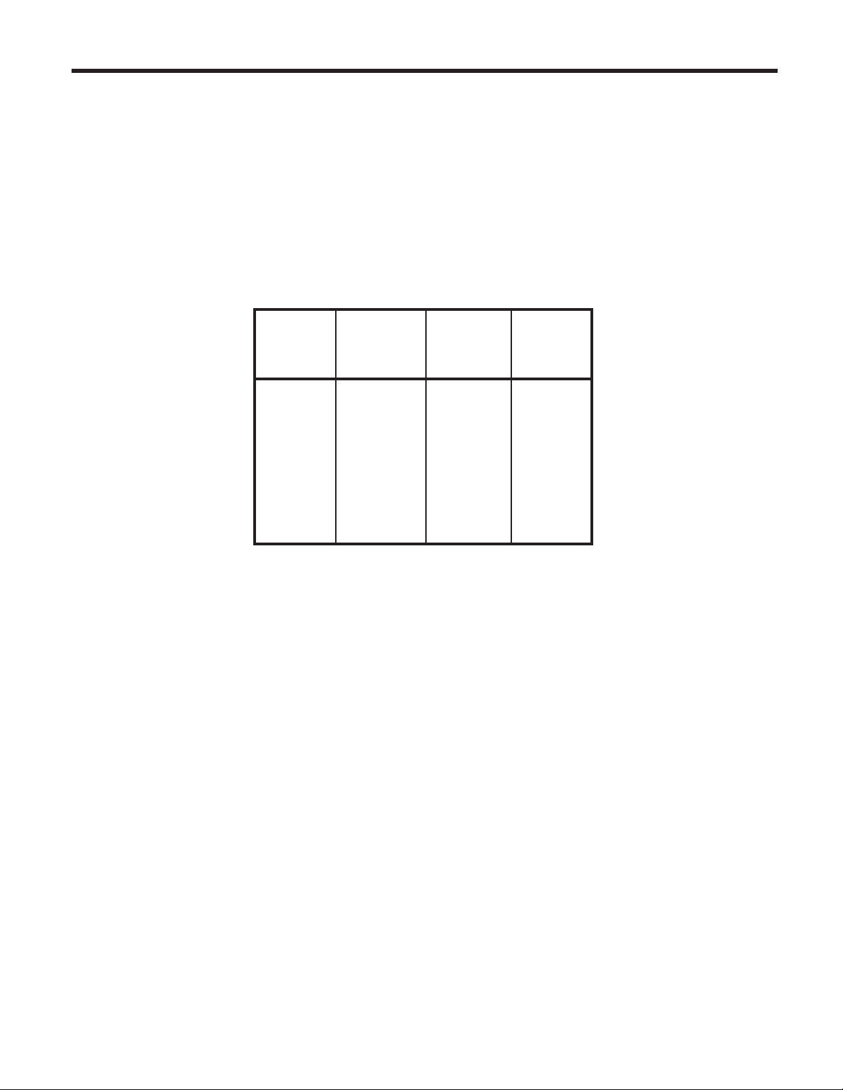
Tips for Design and Use
Rated Derated
Working Surge DC Surge
Voltage Voltage Voltage Voltage
+85°C +85°C +125°C +125°C
2 2.7 1.3 1.7
3 3.9 2.0 2.6
4 5.2 2.7 3.2
5 6.5 3.3 4.0
6 8 4 5
10 13 7 8
16 20 10 12
20 26 13 16
25 32 17 20
35 46 23 28
50 65 33 40
Page 2
Ripple current ratings for all devices can be calculated. For 25°C ripple current ratings, take the square root of the
p
art’s free air maximum power dissipation in watts (from the table below) divided by the maximum ESR rating of the
component listed in the catalog in ohms (where applicable, convert milliohm values to ohms). Apply the temperature
correction factor for temperature above 25°C.
I
Ripple Current (Amps) ESR
Surface Mount Tantalums Dipped
Case Case
Size for power dissipation by case size Size for power dissipation by case size
A 0.075 A 0.045
B 0.085 B 0.050
C 0.110 C 0.055
D 0.150 Temp °C
H 0.165 E 0.065
Z 0.250 +25 1.00 F 0.075 +25 1.00
XL 0.055 +125 0.16 H 0.085 +125 0.09
AL 0.065 J 0.090
BL 0.080 K 0.100
CL 0.090 L 0.1
DL 0.125 M 0.120
P 0.015 O 0.140
R 0.025
Free Air
Max Power
Dissipation (W)
= • Temperature Correction Factor
RMS
√
Temperature Derating Factors Temperature Derating Factors
Do not use these derating factors when calculating
ripple
current ratings. Use temperature correction
factors shown in the formula above.
+85 0.80 G 0.080 +85 0.40
Power Rating
(MAX Watts)
(MAX Ohms)
Free Air
Max Power
Dissipation (W)
Do not use these derating factors when calculating
r
ipple current ratings. Use temperature correction
factors shown in the formula above.
Factor D 0.060 T
10
N 0.130
85°C = 0.90
125°C
= 0.40
Radial
emp °C
Factor
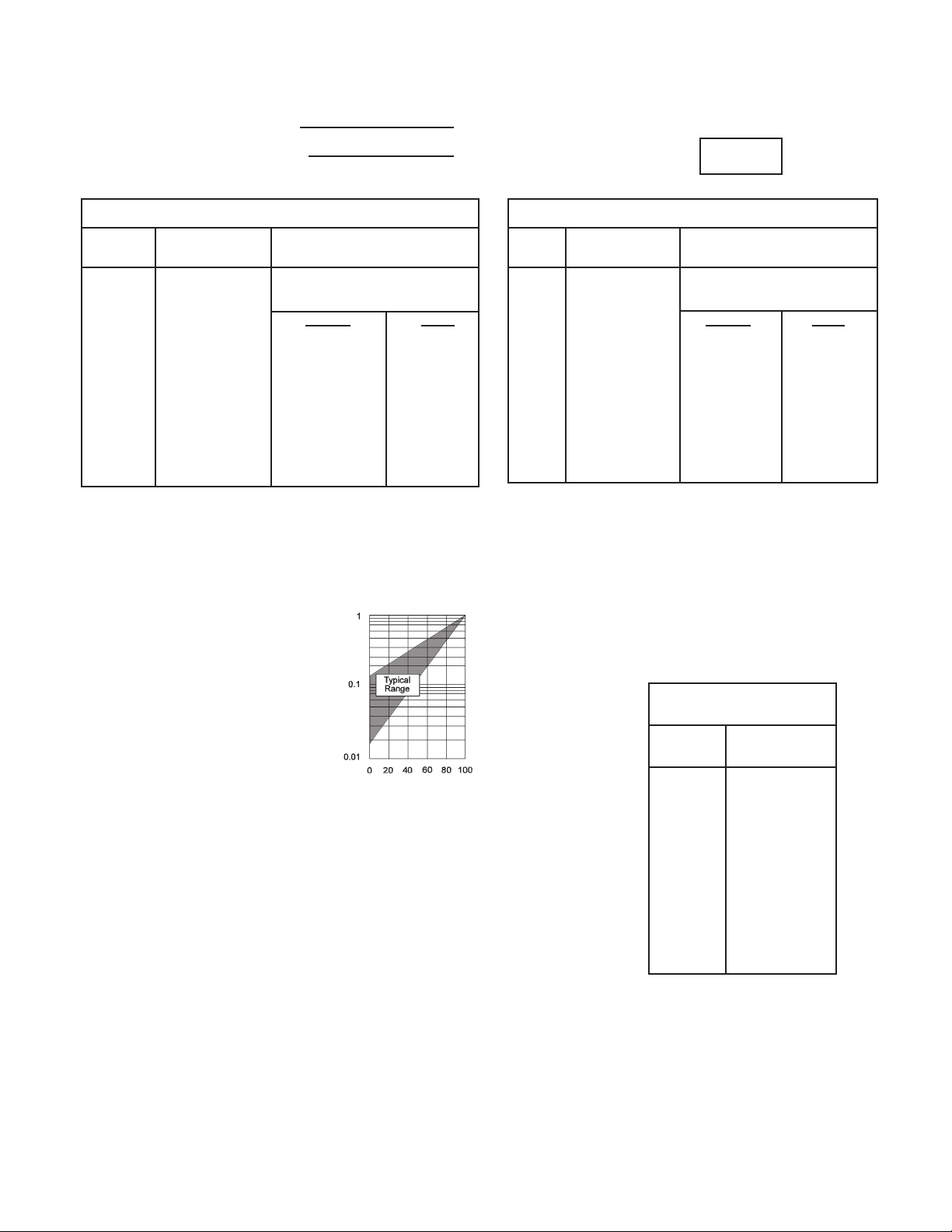
DC Leakage current is dependent on the voltage applied, elapsed time of voltage applied and temperature.
Leakage current is measured after 3-5 minutes application of the rated voltage at +20°C. Leakage current increases
with higher temperatures and can be mitigated by increasing the voltage rating of the part. Leakage current drops
rapidly below the parts initial value when reduced voltages are applied. Voltage derating of the component has the
effect of decreasing leakage as shown in the graph below. This will also give a significant increase in the reliability
of the part for any application.
R
Self Inductance Value
(ESL)
Typical
Self
Inductance
Value (nH)
Leakage Current Ratio I/IV
Rated Voltage (VR) %
Self Inductance Value (ESL) for surface mount devices
The self inductance value can be important for resonance frequency evaluation.
This table shows typical ESL values per case size.
Case
Size
A 1.8
B 1.8
C 2.2
D 2.4
H 2.5
Z 2.4
XL 1.4
AL 1.8
BL 1.8
CL 2.2
DL 2.4
P 1.1
R 1.2
Recommended storage conditions
Solid tantalum capacitors are known to have an infinite shelf life at wa
temperature of
+15°C to +35°C and a relative humidity at 25% to 75%.
rehouse storage conditions maintained at a
Storage conditions at temperatures of -10°C to +50°C are acceptable, but in excess of two years of exposure to these
conditions with high humidity, leakage current may be affected.
37
Page 3

There are several important general soldering considerations for tantalum capacitors.
•
Soldering temperature and time should be the minimum for a good connection.
• Recommended soldering profiles are designed to insure that the temperature of the internal construction of the
capacitors does not exceed +220°C.
• Positioning capacitors near components radiating heat such as power transistors should be avoided.
• Allow for an increase to ESR ratings of 1.25 x catalog limit post PCB assembly.
Lead-free RoHS compliant, 100% Sn termination finish
Legislation is being developed worldwide to reduce the lead content and other hazardous substances in electronic products. This
will reduce the environmental impact when such products are discarded. Nemco products are lead-free devices which meet RoHS
requirements. Optional suffix codes have been added to our part numbering system so either 90/10 Sn/Pb or 100% Sn (lead-free)
can be specified. The following general information applies to lead-free surface mount devices.
IR and Convection reflow
Pre-heating: 150°C +/- 15°C / 60-90s
Maximum peak temperature: 240°C - 260°C, 250°C max recommended
Ramp
rate: 2-3°C/sec.
Maximum time (cumulative) above 230°C 40 seconds.
Cool down should not be forced. 6°C/sec. is recommended.
Wave soldering
PCT, LSR, MCT and CGT: Maximum peak temperature: 250°C - 260°C for 3-5 seconds max (250°C max recommended)
TB: Maximum peak temperature: 230°C - 250°C for 3-5 seconds max (240°C max recommended)
All other parameters remain the same as for IR reflow.
Hand soldering
Soldering iron tip diameter: select to fit application
Maximum tip temperature: +370°C
Maximum exposure time: 3 seconds
Apply heat to pad, not the terminations.
, 10 seconds maximum time at peak, 3 reflow cycles.
Recommended solder alloy for reflow: SnAgCu
lead-free (100% Sn) termination finish is compatible with all common lead-free solder pastes including SnCu, SnCuAgBi, etc.
Recommended solder alloy for wave soldering: SnCu
Recommended solder alloy for hand soldering: SnAgCu
Soldering conditions
Fluxes containing acids must not be used.
Cooling
After soldering, the assembly should preferably be allowed to cool naturally to room temperature. In the event that assisted cooling is used, the rate of change in temperature should not exceed that used in reflow.
Forward compatibility
Parts with Sn/Pb can be used in a lead-free process depending on the solder and solder temperature.
Solders with Bi are not compatible.
Backward compatibility
Lead-free parts (100% Sn termination finish) can be used in a Sn/Pb process. The 100% Sn (Tin) termination finish is compatible
with existing Sn/Pb solder pastes / systems in use today.
RoHS
Nemco lead-free product complies with EU Directive 2002/95/EC on the Restriction of Hazardous Substances requirements.
JEDEC Standard JESD97
Nemco lead-free surface mount devices are in accordance with category e3 terminations.
MSL
PCT, LSR, MCT and TB series moisture sensitivity level per IPC/Jedec J-STD-020B is level 1.
CGT series moisture sensitivity level per IPC/Jedec J-STD-020B is level 3.
Visual standard
Lead-free solder joints are not as bright as tin-lead pastes and the fillet may not be as large.
Resin color
The encapsulant resin color may darken due to the increase in temperature required for the paste.
Self alignment
lead-free solder pastes do not allow the same self alignment as lead containing systems, Standard mounting pads are acceptable,
but machine set up may need to be modified.
Reliability
PCT, LSR, MCT and TB series are 1% per 1,000 hours at 85°C, Vrwith 0.1Ω / V series impedance, 60% confidence level.
CGT series is 0.2% per 1,000 hours at 85°C, 0.5xVrwith 0.1Ω / V series impedance, 60% confidence level.
38
 Loading...