

Page 1
General Performance Information
Introduction
Tantalum capacitors are manufactured from a powder of pure tantalum metal. The powder is compressed under high
pressure around a tantalum wire to form a ‘pellet’. The riser wire is the anode connection to the capacitor. This is subsequently
vacuum sintered at high temperature (typically 1500 - 2000°C). This helps to drive off any impurities within the powder by
migration to the surface. During sintering the powder becomes a sponge like structure with all the particles interconnected in a
huge lattice. This structure is of high mechanical strength and density, but is also highly porous giving a large internal surface area.
The larger the surface area the larger the capacitance. By choosing the powder used to produce each capacitance/voltage
rating, the surface area can be controlled. The next stage is the production of the cathode plate. This is achieved by pyrolysis of
manganese nitrate into manganese dioxide. The ‘pellet’ is dipped into an aqueous solution of nitrate and then baked in an oven
at approximately 250°C to produce a dioxide coat. This process is repeated several times, varying specific densities of nitrate to
build up a thick coat over all internal and external surfaces of the ‘pellet’. The ‘pellet’ is then dipped into graphite and silver to
provide a good connection to the manganese dioxide cathode plate. Electrical contact is established by deposition of carbon onto
the surface of the cathode. The carbon is then coated with a conductive material to facilitate connection to the cathode
termination. Packaging is carried out to meet specifications and customer requirements.
Specifications
Data relates to an ambient temperature of +25° C
z Operating temperature range -55°C to +125°C
PCT, LSR, MCT and TB CGT (Consumer grade) - (linear derating) +40°C to 0.5 x Vr at +85°C and 0.2 x Vr at +125°C.
2/3 x Vr (linear derating) required for operation above +85°C.
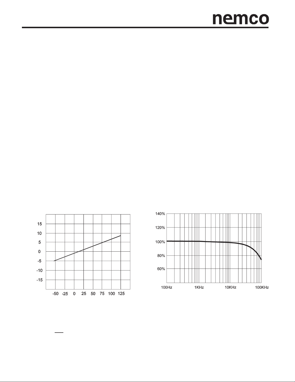
z Capacitance Nominal rated capacitance is measured at +25°C, 120 Hz source, free of harmonics with a maximum bias of
2.2V d.c. Capacitance decreases with increasing frequency and increases with increasing temperature.
Typical Component Typical Component
Capacitance vs. Temperature Capacitance vs. Frequency
Capacitance %
% Capacitance Change
Temperature °C Frequency
z Capacitance tolerances E.I.A. standard ±20% and ±10%.
Tolerance is the permissable variation of the actual value of capacitance from the rated value.
z Stability ΔC ≤ 12% over the operating temperature range
C
z Environmental Classification 55/125/56 (IEC 68-2)
Page 2
General Performance Information
z Working DC voltage range - 4 to 50 WVDC
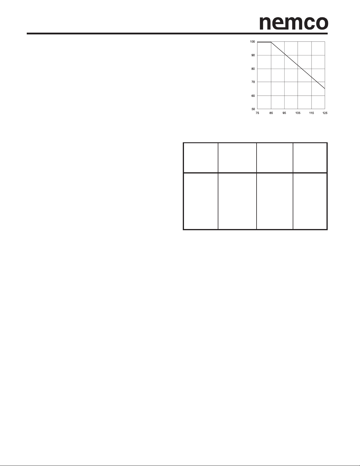
Rated voltages are the maximum recommended peak DC operating
voltages for continuous use from -55°C to +85°C. Operation above
+85°C requires linear derating to 2/3 rated voltage at +125°C.
To improve operating reliability select higher voltage ratings (30% to 70%
recommended) than the maximum line voltage. This is known as
voltage derating. The effects of voltage derating can be seen by
referring to the section on reliability, failure rate.
z Surge Voltage VDC Surge voltage includes the sum of
peak AC ripple, DC bias and any transients. This is the
highest voltage that may be applied to a capacitor for a short
period of time. The surge voltage may be applied up to ten
times in an hour for periods up to 30 sec. at a time. These
values are not intended to apply to continuous operation.
The surge voltage must not be used as a parameter in the
design of circuits in which, in the normal course of operation,
the capacitor is periodically charged and discharged.
The solid tantalum capacitor has a limited ability to
withstand surges due to the fact that they operate at very
high electrical stress within the oxide layer. It is important to
insure that the voltage across the terminals of the capacitor
does not exceed the surge voltage rating at any time. This
is particularly so in low impedance circuits where the
capacitor is likely to be subjected to the full impact of surges.
Even an extremely short duration spike is likely to cause
damage. In such situations it may be necessary to use a
higher voltage rating such as an extended range value and/or a lower ESR device.
Rated Derated
Working Surge DC Surge
Volts Voltage Volts Voltage
+85°C +85°C +125°C +125°C
4 5.2 2.7 3.2
6.3 8 4 5
10 13 7 8
16 20 10 12
20 26 13 16
25 32 17 20
35 46 23 28
50 65 33 40
% Rated Voltage
Temperature °C
Solid tantalum capacitors have a self healing ability due to the manganese dioxide semicoducting layer used as the negative
plate. In the case of low impedance circuits, the capacitor is likely to be stressed by current surges. Derating the capacitor
voltage by 50% or more increases the reliability of the component. In circuits which undergo rapid charge or discharge a
protective resistor of 1Ω/V is recommended. If this is impossible, a derating factor of up to 70% is recommended. In such
situations a higher voltage may be needed than is available as a single capacitor. A series combination can be used to
increase the working voltage of the equivalent capacitor: For example two 22μF 25V parts in series is equivalent to a 11μF
50V part. 1 ohm per volt series resistance is recommended for dynamic conditions which include current in-rush applications
such as inputs to power supply circuits. In many power supply topologies where the di / dt through the capacitor(s) is limited,
(such as most implementations of buck (current mode), forward converter, and flyback), the requirement for series resistance
is decreased. 0.1 ohm per volt series resistance is recommended for steady state conditions. This level of resistance is used
as a basis for the series resistance variable in a 1% /1000 hours 60% confidence level reference. This is what steady state life
tests are based on.
NOTE: Certain test circuits (i.e. ICT) are likely to subject the capacitors to large voltage and current transients, which will not
be seen in normal use. These conditions should be taken into account when considering the capacitor’s rated voltage for use.
This can be controlled by ensuring a correct test resistance is used.
Page 3
General Performance Information
z Reverse voltage A small degree of reverse voltage is permissible for short periods. Limiting reverse voltage excursion to
the maximum limits shown will avoid a reduction in the components life expectancy. The maximum allowable reverse
voltage is summarized as follows:
The values quoted are not intended to cover continuous reverse operation.
They are designed to cover exceptional conditions of small levels into reverse polarity.
Non-Polar operation If higher reverse voltages are unavoidable, then two capacitors, each of twice the required
capacitance and of equal tolerance and rated voltage, should be connected in a back-to-back configuration, i.e. both cathodes
joined together.
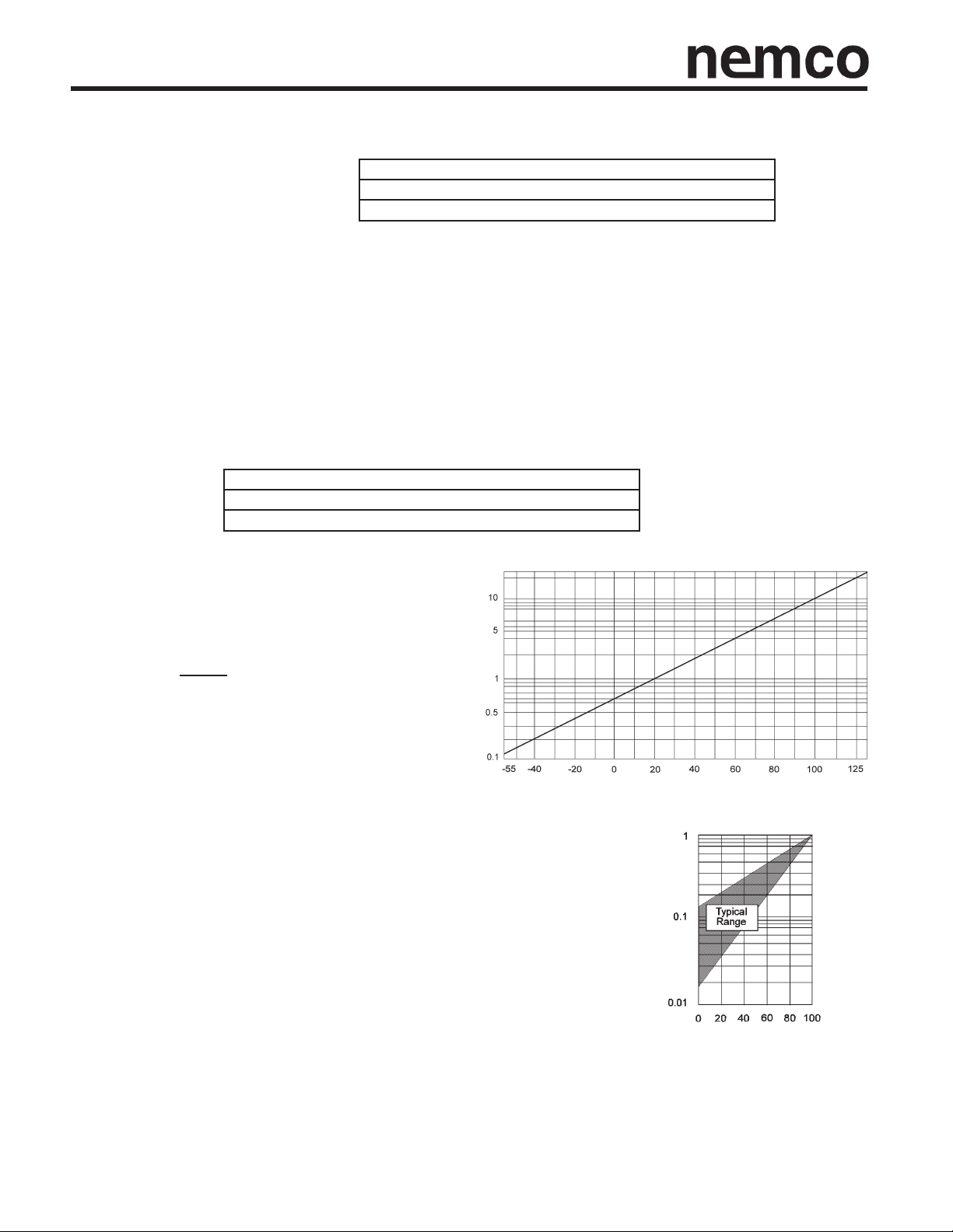
z DC Leakage Current The DC leakage current is the current that, after a three to five minute charging period, flows through
a capacitor when voltage is applied. It is dependent upon the voltage applied, the time the voltage was applied and th ecomponent temperature. The leakage current increases with increasing temperature. The leakage current decreases when
reduced voltages are applied. The DC leakage current is measured at +25°C with rated voltage applied, through a 1000 ohm
resistor connected in series in the measuring circuit. Reforming of solid tantalum capacitors is unnecessary even after prolonged periods without the application of voltage.
@ 25°C the DCL values are shown in part number tables
@ 85°C the DCL should not exceed 10 times the value
@ 125°C the DCL should not exceed 12 times the value
25°C 10% of rated voltage not exceeding 1.0 volt
85°C 3% of rated voltage not exceeding 0.5 volt
125°C 1% of rated voltage not exceeding 0.1 volt
Temperature Dependance of the Leakage Current
For operation between +85°C and +125°C, the
maximum working voltage must be derated and
can be found from the following formula.
V max = 1 - (T - 85) x V
T is the required operating temperature.
Voltage Dependence of the Leakage Current The leakage current drops
rapidly when reduced voltages are applied. The effect of voltage derating on
leakage current gives a significant increase in reliability for any application.
()
120
R
volts
R25
Leakage Current Ratio I/I
Temperature (°C)
R
Leakage Current Ratio I/IV
Rated Voltage UR %
Page 4
General Performance Information
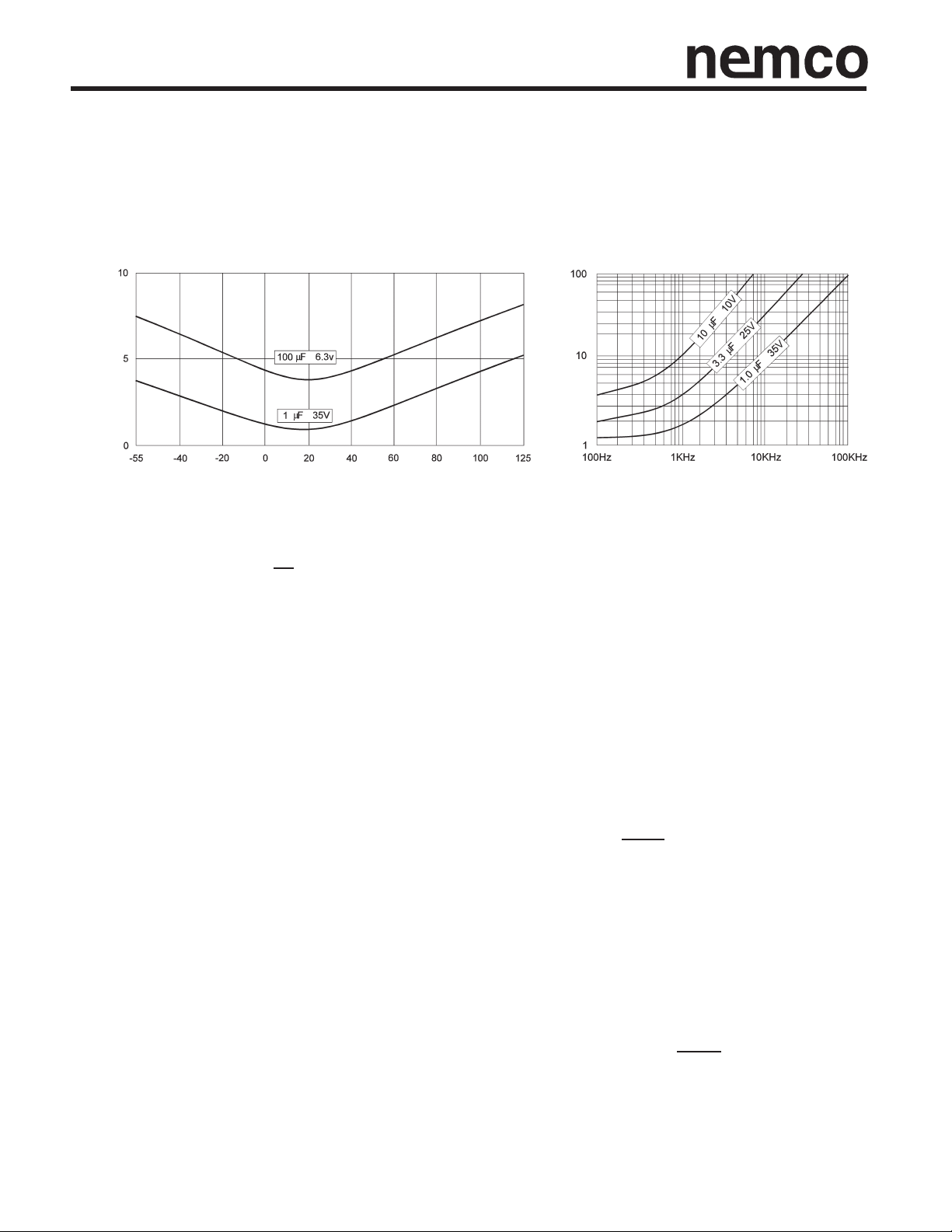
z Tan δ(at 120 Hz/25°C) (DF)
Tangent of Loss Angle is a measurement of the energy loss in the capacitor. Terms also used are power factor, loss factor,
quality factor, “Q” (the reciprocal of DF) and DF which is the measurement of Tan δ expressed as a percentage. Tan δ is the
power loss of the capacitor divided by its reactive power at a sinusoidal voltage of a specified frequency. Measurement is
carried out at +25°C and 120Hz with 2.2V DC bias max., with an a.c. voltage free of harmonics. The value of Tan δ
is temperature and frequency dependent. DF increases with increasing frequency. DF loses its importance at higher
frequencies where impedance and ESR are the normal parameters of concern.
Typical Curve Typical Curve
Dissipation Factor (D.F.) vs. Temperature Dissipation Factor (D.F.) vs. Frequency
DF %
Temperature °C Frequency
Tan δ (DF) values are indicated in part number tables. The values shown in the part number tables are the limits met by the
component after soldering onto the substrate.
Tan δ (DF) = R = 2πƒCR Tan δ (DF) = Dissipation factor
X
c
X
z Impedance Impedance is the ratio of voltage to current at a specified frequency. Three factors contribute to the
impedance of a tantalum capacitor; the resistance of the semiconductor layer; the capacitance value and the
inductance of the electrodes and terminations. At high frequencies the inductance of the terminations becomes
a limiting factor. The temperature and frequency behavior of these three factors of impedance determine the
behavior of the impedance. The impedance is measured at +25°C and 100KHz. There is unavoidable
inductance as well as resistance in all capacitors. At some point in frequency, the reactance stops being capacitive and becomes inductive. This frequency is the self resonant point and typically falls between 0.5 - 5MHz
depending on the rating. In solid tantalum capacitors, resonance is damped by the ESR and a smooth transition from capacitive to inductive reactance occurs. Total Impedance of the capacitor can be viewed as:
DF %
R = ESR (ohms)
= Capacitive reactance (ohms)
c
ƒ = Frequency (Hertz)
C = Series capacitance (Farads)
Below resonance - The vector sum of capacitive reactance. X
Above resonance - The vector sum of inductive reactance. ( X
ƒ = frequency, Hertz C = capacitance,farad L = inductance, Henries
z ESR Equivalent Series Resistance (ESR) is the preferred high frequency statement of the unavoidable resistance
appearing in tantalum capacitors. Maximum limits for 100 kHz ESR are listed in the part number tables. NOTE:
Nemco LSR series is specifically designed for low ESR performance. Resistance losses occur in all practical forms
of capacitors. These are made up from several different mechanisms, including resistance in components and
contacts, viscous forces within the dielectric and defects producing bypass current paths. To express the effect of
these losses they are considered as the ESR of the capacitor. The ESR is measured at +25°C and 100KHz. The
ESR is frequency dependent and can be found by using the relationship; ESR = Tan δ
Where ƒ is the frequency in Hertz, and C is the capacitance in farads.
ESR is one of the contributing factors to impedance. At high frequencies (100KHz and above) it becomes the
dominant factor. ESR and impedance become almost identical, impedance being only marginally higher.
= 1 ohm and ESR
c
()
2πƒc
= 2πƒL ) and ESR
L
2πƒC
Page 5

General Performance Information
z Frequency Dependence of
Impedance and ESR
ESR and impedance decrease with increasing
frequency. At lower frequencies the extra
contribution to impedance due to the
reactance of the capacitor becomes more
significant. Beyond the resonant point of the
capacitor, impedance again increases due to
the inductance of the capacitor.
Typical response curve to frequency.
ESR, Impedance (Ω)
Frequency (Hz)
z Temperature Dependence of
Impedance and ESR
At 100KHz, impedance and ESR behave
identically. Impedance and ESR decrease
with increasing temperature. The amount of
change is influenced by the size of the
capacitor and is generally more pronounced
on smaller ratings.
Typical effect of temperature on 100KHz ESR
can be seen by applying a multiplier to
100kHz ESR.
ESR, Impedance
Multiplier of 100kHz ESR
Temperature (°C)
Temperature Dependance of the Impedance and ESR
Z (Ω)
Temperature °C
Page 6

General Performance Information
z AC Operation Ripple ratings for all devices can be calculated with the power dissipation rating and ESR rating of the com-
ponent. Calculated ripple ratings are based on a free air environment. In an AC application heat is generated within the capacitor by both the AC component of the signal (which will depend upon the signal form, amplitude and frequency), and by the
DC leakage. For practical purposes the DCL is insignificant. Permissible AC ripple voltage and current are related to ESR
and power dissipation capability. Actual power dissipated can be calculated from the following formula:
I = rms ripple current (amperes)
R = equivalent series resistance at specified frequency (ohms)
E = rms ripple voltage (volts)
P = power dissipated (watts)
Z = impedance at frequency under consideration (ohms)
Using this formula it is possible to calculate the maximum a.c. ripple current and voltage permissible for a particular
application.
Maximum allowable rms ripple voltage or ripple current may be determined taking into account three limiting factors.
1. The d.c. working voltage of the capacitor must not be exceeded by the sum of the positive peak of the applied a.c. voltage
and the d.c. bias voltage.
2. The sum of the applied d.c. voltage and the negative peak of the a.c. voltage must not allow a voltage reversal in excess
of that defined in “Reverse Voltage”.
3. The power dissipated in the ESR of the capacitor must not exceed the power dissipation rating for the case size.
NOTE: Temperature derating factors to power dissipation ratings for case size must be considered in calculations.
2
P= I
R=E2R (substituting I = E )
2
Z
Z
I
RMS
I
RMS
P
T
RIPPLE CURRENT RIPPLE VOLTAGE
=P
√
MAXTDF
ESR
= rms current (amps) X
= Power Dissipation rating (watts) h = Inductance (Negligible at Low ƒ)
MAX
= Temperature derating factor X
DF
85°C = 0.90
125°C = 0.40
E
E
=(X
RMS
RMS
L
C
√
= rms ripple voltage
=2πƒh ƒ = Frequency (of interest)
=½πƒc ƒ = Frequency (of interest)
- XC)2+ (ESR)2•I
L
c = Capacitance (Farad)
ESR = ESR (at ƒ of interest)
I
= rms ripple current
RMS
RMS
Page 7

General Performance Information
Power Dissipation
•
The maximum power dissipation at 25°C has been calculated for the various ranges, and are shown (see Table) together with
temperature derating factors up to 125°C. For leaded components the values are calculated for parts supported in air by their
leads (free space dissipation). For surface mount components, the free air values can be approached by correct thermal management of the board. Operation in confined spaces with no heat sinking may lead to a tenfold reduction in the dissipation
required to heat the capacitors to 10°C above their ambient. The ripple ratings are set by defining the maximum temperature
rise allowable under worst case conditions, i.e. with resistive losses at their maximum limit. This differential is normally at 10°C
at room temperature dropping to 2°C at 125°C. In application (this is particularly critical for surface mount components) circuit layout, thermal management, available ventilation and signal waveform may significantly affect the values. It is recommended that temperature differential between the device and the ambient temperature is less than 10°C up to 85°C and less
than 2°C between 85°C and 125°C. Derating factors for temperatures above 25°C are also shown. The maximum permissible power dissipation should be multiplied by the appropriate derating factor. For certain applications, e.g. power supply filtering, it may be desirable to obtain a Low ESR device to enable higher ripple currents to be handled. Please contact our technical sales office for discussion.
Surface Mount Tantalums Dipped Radial
Case Case
Size for power dissipation by case size Size for power dissipation by case size
A 0.075 A 0.045
B 0.085 B 0.050
C 0.110 C 0.055
D 0.150 T
H 0.165 E 0.065
Z 0.250 +25 1.00 F 0.075 +25 1.00
XL 0.055 +125 0.16 H 0.085 +125 0.09
AL 0.065 J 0.090
BL 0.080 K 0.100
CL 0.090 L 0.110
DL 0.125 M 0.120
P 0.015 O 0.140
R 0.025
Free Air
Max Power
Dissipation (W)
Temperature Derating Factors Temperature Derating Factors
Do not use these derating factors when calculating
ripple current ratings. Use temperature correction
factors.
emp °C Factor D 0.060 Temp °C Factor
+85 0.80 G 0.080 +85 0.40
N 0.130
Free Air
Max Power
Dissipation (W)
Do not use these derating factors when calculating
ripple current ratings. Use temperature correction
factors.
Self Inductance Value (ESL) for surface mount devices
•
The self inductance value can be important for resonance frequency evaluation.
This table shows typical ESL values per case size.
Self Inductance Value
(ESL)
Case
Size
A 1.8
B 1.8
C 2.2
D 2.4
H 2.5
Z 2.4
XL 1.4
AL 1.8
BL 1.8
CL 2.2
DL 2.4
P 1.1
R 1.2
Typical
Self Inductance
Value (nH)
Page 8

General Technical Information
z Reliability Tantalum capacitors have no known wear-out mechanism and in certain circumstances are capable of
self-healing. Random failures can still occur in operation. The failure rate will decrease with time and not
increase as with other capacitor types and other electronic components. The reliability of solid tantalum
capacitors is dependent upon three key factors which affect the working environment and operating conditions:
Operating voltage
Operating temperature
Circuit impedance
Operational reliability generally increases with reduction of applied voltage and temperature and with an increase
of series resistance.
PCT, LSR, MCT and TB series:
1% per 1,000 hours at 85°C, Vrwith 0.1Ω / V series impedance, 60% confidence level.
CGT series:
.2% per 1,000 hours at 85°C, 0.5xVrwith 0.1Ω / V series impedance, 60% confidence level.
z Base Failure Rate Standard tantalum product conforms to Level M reliability (i.e. 1%/1000 hours) at rated voltage, rated
temperature (+85°C) and 0.1Ω/volt circuit impedance. This is known as the base failure rate, F
is used for calculating operating reliability. The effect of varying the operating conditions on failure rate
are shown.
z Reliability Assessment
Operational reliability F in any circuit condition can be deduced from the three previous graphs by multiplying the base failure
rate, F
, for the series by the correction factors, FU, FT, and FR.
B
Worked example of reliability calculation. For a capacitor with a 16v rating, being operated on a 10v line with 0.8Ω per volt
circuit impedance, at a temperature of 50°C, the correction factors given by the previous F
graphs are as follows: F
For a series with F
= 1%/1000 hours, the failure rate F will be F = FUx FTx FRx F
B
B
F
U
T
R
= 0.04
= 0.1
= 0.2
= (0.04 x 0.1 x 0.2 x 1)%/1000 hours
= 0.0008% per 1000 hours at 60% confidence level
, which
B
It should be noted that the above analysis refers to steady state operating conditions. The failure rate will also be affected by
the presence of surges.
Page 9

General Performance Information
z Operating Voltage/Voltage Derating If a capacitor with a higher
voltage rating than the maximum line voltage is used, then the operating
reliability will be improved. This is known as voltage derating. The graph
shows the relationship between voltage derating (the ratio between
applied and rated voltage) and the failure rate. The graph gives the
correction factor F
Effect of applied voltage on basic failure rate for typical component
z Operating Temperature If the operating temperature is below the rated
temperature for the capacitor then the operating reliability will be improved
as shown. This graph gives a correction factor Ft for any temperature of
operation.
for any operating voltage.
U
(60% confidence level).
U
Correction Factor F
(Failure Rate 1% / 1000 hrs.)
Percent Rated Voltage U/UR(%)
T
Correction Factor to Failure Rate F for Ambient Temperature T
for typical component
z Circuit Impedance All solid tantalum capacitors benefit from current limiting to
prevent burning of the device. A series resistor is recommended for this purpose.
A lower circuit impedance may cause an increase in failure rate, especially at temperatures higher than 25°C. An inductive low impedance circuit may apply voltage
surges to the capacitor and similarly a non-inductive low impedance circuit may
apply current surges to the capacitor, causing localized over-heating and failure.
The recommended circuit impedance is 1 ohm per volt. Where this is not feasible,
equivalent voltage derating should be used. The graph shows the correction factor,
F
, for increasing series resistance.
R
Correction Factor to Failure Rate for Series Resistance R on Basic
Failure Rate F
for typical component
B
Correction Factor F
Temperature °C
R
Correction Factor F
Page 10

General Performance Information
Surface Mount
z Life test Capacitors are subjected to +85°C at rated
voltage and +125°C at 2/3 x rated voltage for 2000 hours
with 3 ohms circuit impedance. The capacitors must meet
the following limits after stabilizing at 25°C.
z Humidity test Capacitors are subjected to damp heat
at steady state +40°C with 95% relative humidity. The
capacitors must meet the following limits after stabilizing at
25°C.
z Thermal shock Capacitors are subjected to 5 cycles of 30
minutes at -55°C followed by 30 minutes at +125°C. The
capacitors must meet the following limits after stabilizing at
25°C.
z Surge Current Capacitors shall withstand 3 consecutive
cycles. The capacitors are charged approximately 4
seconds at rated voltage thru a low circuit resistance of
approximately 1 ohm @ +25°C followed by a discharge to
below 1% of rated voltage. Post test readings must meet
the following criteria:
capacitance change within +/-10% of the initial value
Tan δ (DF) within the initial value
DC leakage current within 125% of the initial value
capacitance change within +/-5% of the initial value
Tan δ (DF) within 125% of the initial value
DC leakage current within 125% of the initial value
capacitance change within +/-5% of the initial value
Tan δ (DF) within the initial value
DC leakage current within the initial value
capacitance change less than +/-5% of the initial value
Tan δ (DF) within the initial limit
DC leakage current within the initial limit
z Surge Voltage Surge voltages are performed at +25°C,
+85°C and +125°C. Capacitors are subject to 1000 cycles
of 1.3 x rated voltage for 30 seconds followed by a 30
second discharge period. After stabilizing at room
temperature post test readings must meet the following
criteria.
capacitance change less than +/-5% of the initial value
Tan δ (DF) within the initial limit
DC leakage current within the initial limit
Page 11

General Performance Information
Radial Dipped
z Life test Our regular quality assurance program requires
capacitors be subjected to +85°C at rated voltage and
+125°C at 2/3 x rated voltage for 2000 hours with 3 ohms
circuit impedance. The capacitors must meet the following
limits after stabilizing for 1 - 2 hours at room temperature.
z Humidity life test Capacitors shall be capable of
withstanding 1000 hours at +55°C with 95% RH and rated
voltage applied. The capacitors must meet the following
limits after stabilizing for 24 hours at 25°C.
z Thermal Shock Test Capacitors are subjected to 5 cycles
of 30 minute durations at -55°C followed by 30 minutes at
+125°C. The capacitors must meet the following limits after
stabilizing at 25°C.
z Surge Current Capacitors shall withstand 3 consecutive
cycles. The capacitors are charged approximately 4
seconds at rated voltage thru a low circuit resistance of
approximately 1 ohm @ +25°C followed by a discharge to
below 1% of rated voltage. Post test readings must meet
the following criteria:
capacitance change within +/-10% of the initial value
Tan δ (DF) within the initial value
DC leakage current within 125% of the initial value
capacitance change within +/-10% of the initial value
Tan δ (DF) less than 2X the initial limit
DC leakage current less than 5X the initial limit
capacitance change within +/-5% of the initial value
Tan δ (DF) within the initial limit
DC leakage current within 125% of the initial limit
capacitance change less than +/-5% of the initial value
Tan δ (DF) within the initial limit
DC leakage current within the initial limit
z Surge Voltage Test Surge voltage tests are performed at
+25°C, +85°C and +125°C. The capacitors shall be applied
a surge voltage in series with a 33 Ω resistor at a cycle of .5
minutes “on” and 5.5 minutes “off” repeating 1000 times at
+85°C. After stabilizing at room temperature the
capacitor must meet the following limits.
capacitance change within +/-10% of the initial value
Tan δ (DF) within the initial limit
DC leakage current within the initial limit
Page 12

General Performance Information
z Mechanical properties
Tantalum chip capacitors are mechanically robust, meeting requirements for high speed insertion machines and the needs of
most automotive and aerospace applications. The performance specifications:
Acceleration 10 g (98.1 m/s
Vibration severity 10 to 2000 Hz, 0.75mm of 10 g (98.1 m/s
Shock Trapezoidal Pulse 10 g (98.1 m/s
2
)
2
2
) for 6 ms
)
Adhesion to substrate Nemco chip components meet IEC 384-3. This requires a minimum adhesive to substrate strength
of 5 Newtons.
Resistance to substrate bending and expansion Because the component has compliant leads, thermal mismatch
between the component and substrate (ceramic, FR4, etc.) or bending of the substrate itself, will not normally give rise to
stress at the solder joint and will enhance the temperature cycling capability of the finished board.
Solderability Meets the requirements of IEC 68 2.20 Test Ta and MIL-STD-202, Method 208.
Stand off and glue pad The glue-pad on the PCT and LSR types aid high volume insertion: the surface of the pad is
etched to provide a strong mechanical key to the glue, and the reduced clearance allows the use of ultraviolet cured epoxies.
For the A, B, and P cases, the stand-off is 0.05±0.05 mm; for C, D, and H cases, it is 0.1±0.1 mm.
Flammability UL Rating UL94 VO, Oxygen Index 35%. Epoxy, Hysol MG 33.
Resistance to board cleaning Nemco tantalum chips have excellent solderability characteristics and are compatible with
mildly activated (RMA) or pure resin flux systems. The use of high acidity fluxes must be avoided. The encapsulation and
termination materials are resistant to immersion in boiling solvents such as: Freon TMS and TMC, Trichloroethane, Methylene
Chloride, Isopropyl alcohol (IPA), etc., up to 50°C. If ultrasonic cleaning is to be applied in the final wash stages the
application time should be less than 5 minutes with a maximum power density of 9 mW/cc to avoid damage to terminations.
Care should also be taken to ensure that boards are firmly held and that adjacent boards are not allowed to contact each other.
Nemco tantalum chips are also compatible with newer aqueous and semi-aqueous processes.
Thermal Management.
The heat generated inside a tantalum capacitor in a.c. operation comes from the power dissipation due to ripple current. The
heat will be transferred from the outer surface by conduction. How efficiently it is transferred from this point is dependent on
the thermal management of the board.
Power dissipation ratings are based on free-air calculations. These ratings can be approached if efficient heat sinking and/or
forced cooling is used.
In practice, in a high density assembly with no specific thermal management, the power dissipation required to give a 10°C
rise above ambient may be up to a factor of 10 less. In these cases, the actual capacitor temperature should be established
(either by thermocouple probe or infra-red scanner) and if it is seen to be above this limit it may be necessary to specify a
lower ESR part or a higher voltage rating.
 Loading...