

Page 1

NVHMI SERIES User Manual www.nemavision-ipc.com
1
NVHMI-7 SERIES User Manual
Release Date _ Revision
Apr. 2013 V1.0
Page 2

NVHMI SERIES User Manual www.nemavision-ipc.com
2
Warning!___________________________________
This equipment generates, uses and can radiate radio frequency energy and if not installed and
used in accordance with the instructions manual, it may cause interference to radio communications.
It has been tested and found to comply with the limits for a Class A computing device pursuant to
FCC Rules, which are designed to provide reasonable protection against such interference when
operated in a commercial environment. Operation of this equipment in a residential area is likely
to cause interference in which case the user at his own expense will be required to take whatever
measures may be required to correct the interference.
Disclaimer
This information in this document is subject to change without notice. In no event shall
Nemavision-iPC/Aplex Technology Inc. be liable for damages of any kind, whether incidental or
consequential, arising from either the use or misuse of information in this document or in any
related materials.
Electric Shock Hazard – Do not operate the machine with its back cover removed. There are
dangerous high voltages inside.
Page 3

NVHMI SERIES User Manual www.nemavision-ipc.com
3
Packing List
Accessories (as ticked) included in this package are:
AC power cable
Driver & manual CD disc
Other.___________________(please specify)
Safety Precautions
Follow the messages below to prevent your systems from damage:
Avoid your system from static electricity on all occasions.
Prevent electric shock. Don‘t touch any components of this card when the card is
power-on. Always disconnect power when the system is not in use.
Disconnect power when you change any hardware devices. For instance, when you
connect a jumper or install any cards, a surge of power may damage the electronic
components or the whole system.
Page 4

NVHMI SERIES User Manual www.nemavision-ipc.com
4
Table of Contents______________________
Warning!…………………………………………………………………………….……..….2
Disclaimer………………………………………………………………….…………………2
Packing List…………………………………………………………………………………..3
Safety Precautions…………………………………………………………………………..3
Chapter 1 Getting Started
1.1 Specifications……………………………………..….……………………..6
1.2 Dimensions………………………………...………………………….......7
1.3 Brief Description………………………………………………….………10
1.4 Installation of HDD………………………………………………………11
Chapter 2 Hardware
2.1 Mainboard………………..…….……………………………………..…..15
2.2 Installations…….………………….……………………………………...18
2.3 Jumpers Setting and Connectors........................................................19
Chapter 3 BIOS Setup
3.1 Operations after POST Screen.............................................................28
3.2 BIOS SETUP UTILITY..........................................................................29
3.3 Main Settings…....................................................................................29
3.4 Advanced Settings............................................................................... 31
3.5 Chipset Settings................................................................................... 37
3.6 Boot Settings....................................................................................... 41
3.7 Security Settings.................................................................................. 44
3.8 Save and Exist Settings....................................................................... 45
3.9 Exit Options..........................................................................................51
Chapter 4 Installation of Drivers
4.1 Intel Chipset Driver.…………………………...…………………………54
4.2 Intel Graphics Media Accelerator Driver...……………………………..57
4.3 Intel (R) Network Adapter……..………………………………………….60
4.4 Realtek ALC662 HD Audio Driver Installation…….………….…………62
Chapter 5 Touch Screen Installation
5.2 Windows 2000/XP USB Driver Installation for PenMount 6000Series.64
5.1.1 Installing Software (Resistive Touch).................................................64
Page 5

NVHMI SERIES User Manual www.nemavision-ipc.com
5
5.1.2 Installing Software (Projected Capacitive)..........................................69
5.2.1 Software Functions(Resistive Touch).................................................74
5.2.2 Software Functions(Projected Capacitive)………….………………….85
Figures
Figure 1.1:Dimensions of NVHMI-707…………………………………..…....7
Figure 1.2:Dimensions of NVHMI-708…………………………………..…....8
Figure 1.3:Dimensions of NVHMI-712…………………………………….8
Figure 1.3:Dimensions of NVHMI-715…………………………………….9
Figure 1.4: Front View of NVHMI SERIES………………………………...10
Figure 1.5: Rear View of NVHMI-707/NVHMI-708……………………..10
Figure 1.5: Rear View of NV HMI-712/NVHMI-715……………………..11
Figure 2.1: Mainboard Dimensions…………………………………..…….....17
Figure 2.2: Jumpers and Connectors Location_ Board Top………………...18
Figure 2.3: Jumpers and Connectors Location_ Board Bottom…………....19
Page 6

NVHMI SERIES User Manual www.nemavision-ipc.com
6
Chapter 1 System
1.1 Specifications
NVHMI-707(P)
NVHMI-708(P)
NVHMI-712(P)
NVHMI-715(P)
System
CPU
Intel Atom Cedar View N2600 1.6GHz Dual Core Processors
System Chipset
Intel NM10
System Memory
Onboard DDR3 2GB 800 MHz
IO Port
USB
2 x USB 2.0 type A, USB4/5
Serial/Parallel
1 x RS-232/422/485 DB-9, COM1, Default RS-232
1 x RS-232 DB-9, COM2
Audio
1 x Line out phone jack
LAN
2 x GbE RJ-45
Power
3 pins terminal block connector, DC Power input
Storage Space
HDD
1 x 2.5” SATA 2 half size
1 x 2.5” SATA 2
Movable device
1 x Internal SD slot
1 x Internal SD slot
Expansion
On board
expansion bus
1 x Mini-PCIe half size
Display
Display Type
7” TFT-LCD
8” TFT-LCD
12.1” TFT-LCD
15” TFT-LCD
Max. Resolution
800x480
800x600
800x600
1024x768
Max. Color
262K
16.2M
16.2M
16.2M
Luminance
(cd/m²)
350
350
330
330
View
angle(H°/V°)
140/110
140/125
160/140
170/170
Touch screen
Type
Resistive Touch / Projected Capacitive Touch (for P model)
Interface
RS-232 / USB (for P model)
Light
Transmission(%)
80% / 90% (for P model)
Page 7
NVHMI SERIES User Manual www.nemavision-ipc.com
7
Power
Power Input
9~36V DC
Mechanical
Construction
Sliver aluminum front bezel and chassis
IP Rating
IP65 front panel
Mounting
Panel mounting, VESA 75 x 75
Panel mounting, VESA 100 x 100
Dimension (mm)
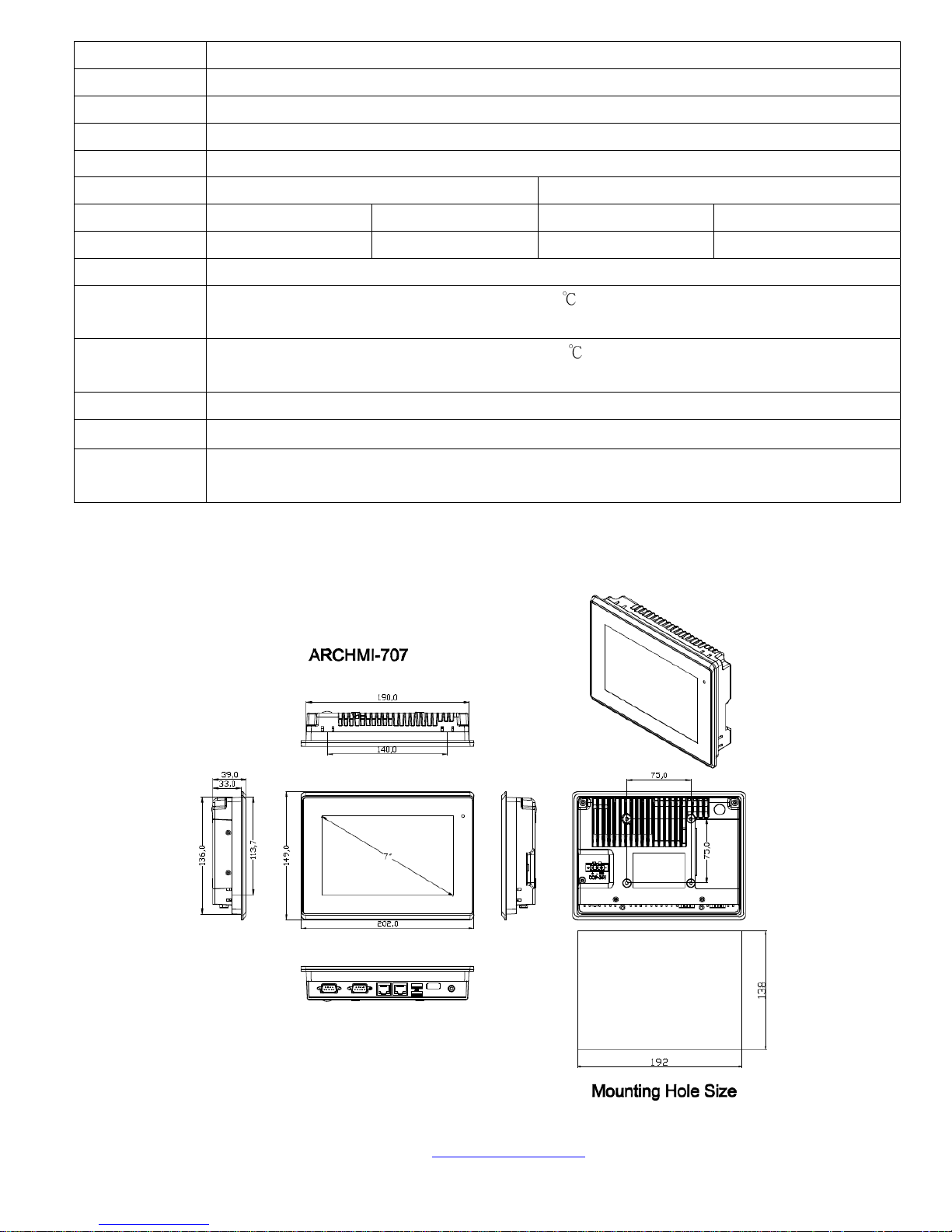
202 x 149 x 39
231 x 176 x 51
319 x 245 x 51.68
410 x 310 x 54.67
Net Weight (Kgs)
2.3
3.2
4.0
6.3
Environmental
Operatiing
temperature(°C)
0~50
Storage
temperature(°C)
-20~60
Storage humidity
10 to 90% @ 40°C, non- condensing
Certification
CE / FCC Class A
Operating
System Support
Windows XP pro, Windows XP Embedded, Windows Embedded CE6.0(Note 1), Windows 7 pro for
Embedded Windows Embedded standard 7(Win 7 support 3D Graphic function)
Note 1: NVHMI series is covered by one or more of the following patents: US6, 570, 884, US6,115,776, and US6,327,625.
1.2 Dimensions
Figure 1.1: Dimensions of NVHMI-707
Page 8
NVHMI SERIES User Manual www.nemavision-ipc.com
8
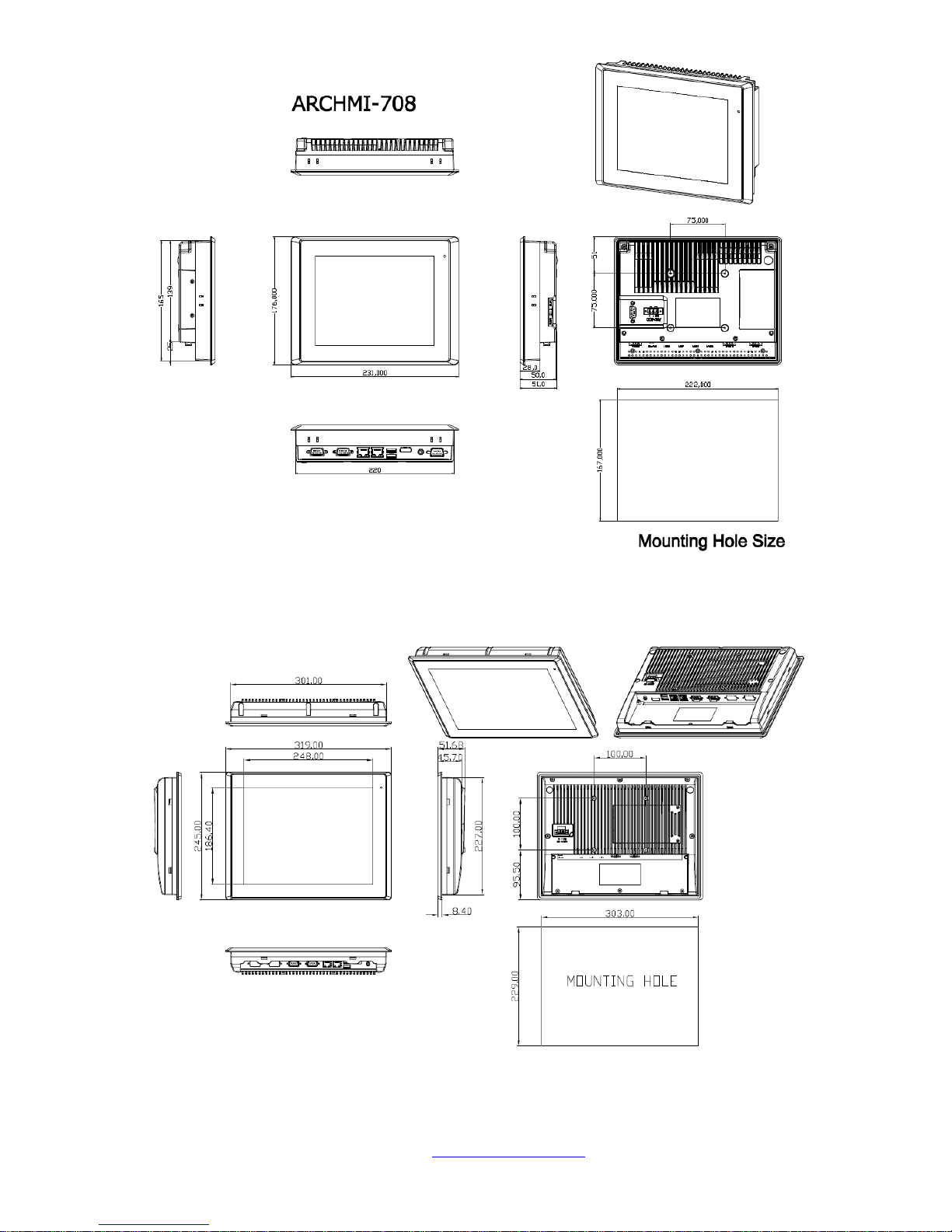
Figure 1.2: Dimensions of NVHMI-708
Figure 1.3: Dimensions of NVHMI-712
Page 9

NVHMI SERIES User Manual www.nemavision-ipc.com
9
Figure 1.4: Dimensions of NVHMI-715
Page 10
NVHMI SERIES User Manual www.nemavision-ipc.com
10
1.3 Brief Description of NVHMI SERIES
There are 7”, 8”, 12”,15” Industrial Compact Size Panel PC in NVHMI series, which comes with flat
front panel touch screen and fanless design. It is powered by an Intel Atom N2600 1.6GHz CPU
built-in, 2GB DDR III 800 MHz. NVhmi series is 9~36VDC wide-ranging power input and IP65
compliant front panel. Optional projected capacitive touchscreen support 7H anti-scratch surface is
ideal for use as a PC-based controller for Industrial Automation & Factory Automation.
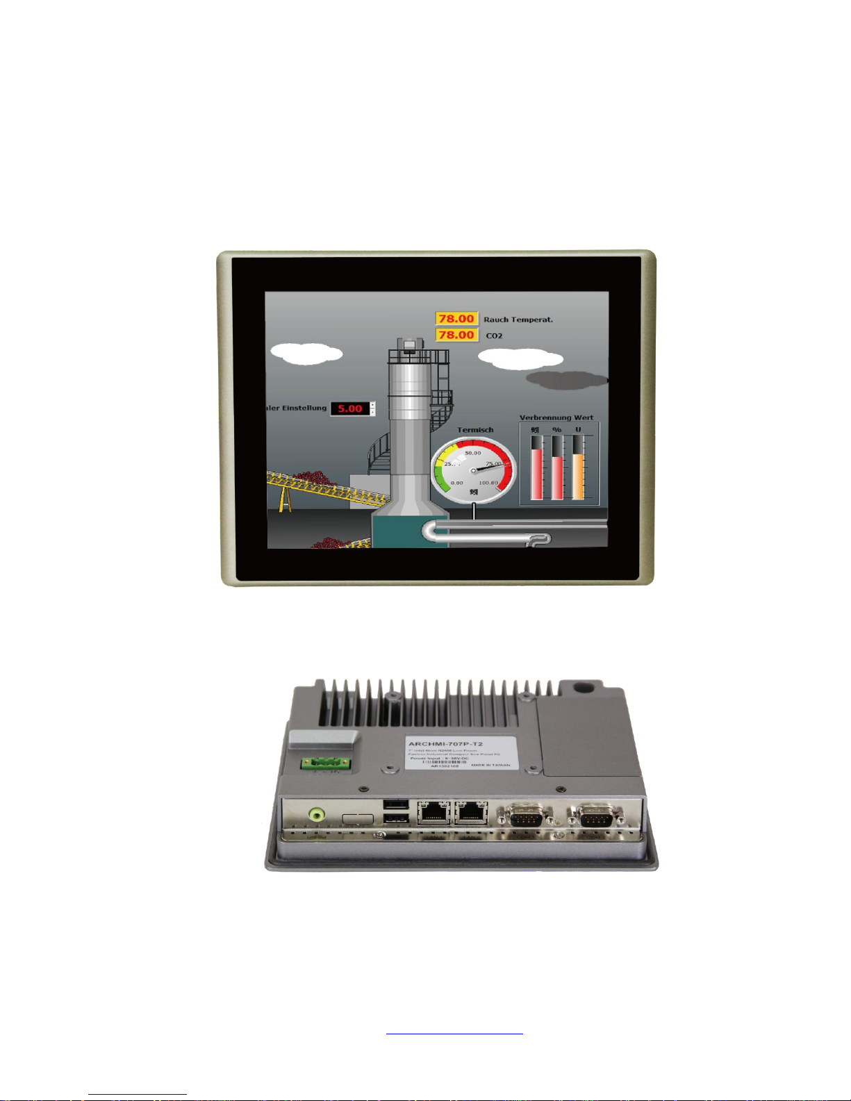
Figure 1.5: Front View of NVHMI SERIES
Figure 1.6: Rear View of NVHMI -707/NVHMI -708
Page 11
NVHMI SERIES User Manual www.nemavision-ipc.com
11
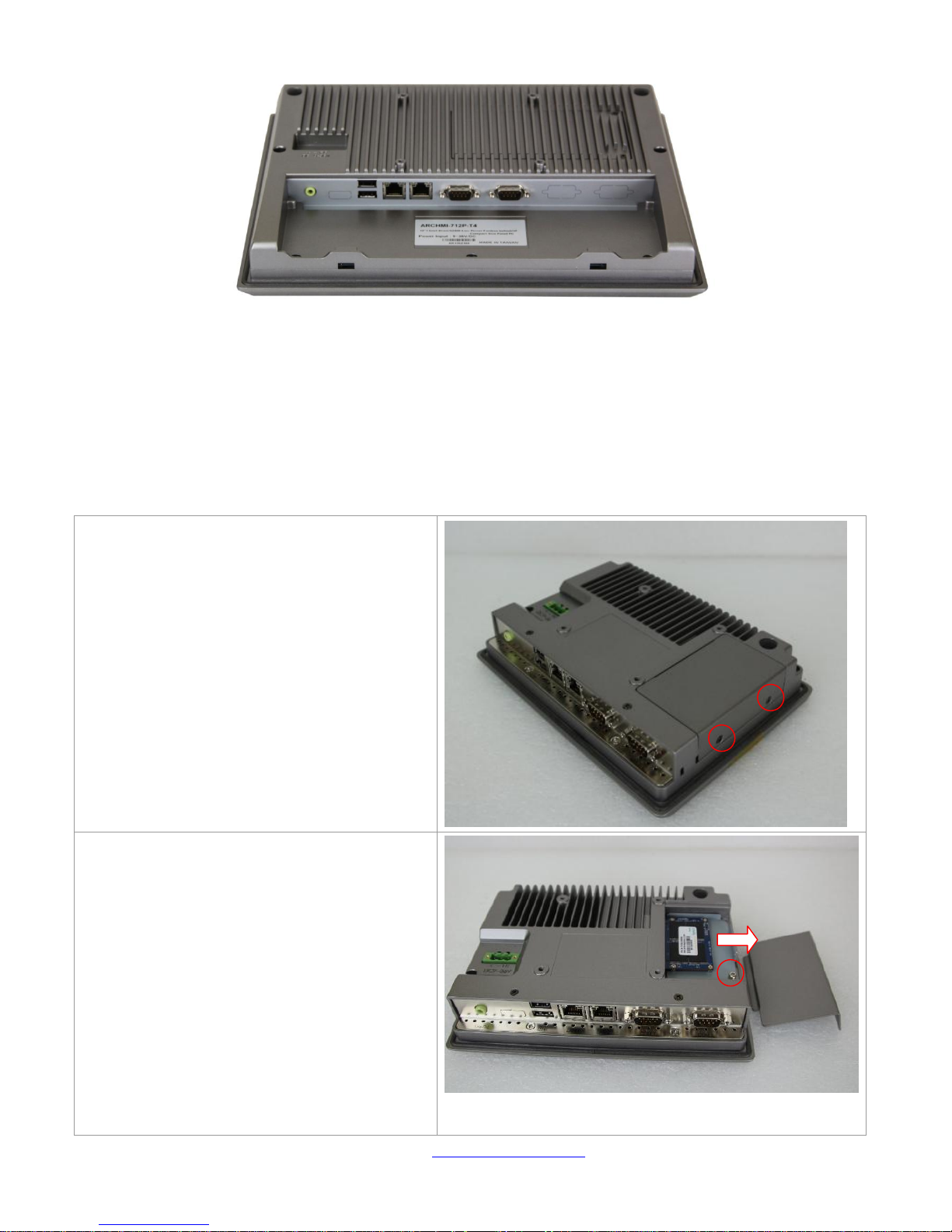
Figure 1.7: Rear View of NVHMI -712/ NVHMI- 715
1.4 Installation of HDD(NVHMI-707/NVHMI-708)
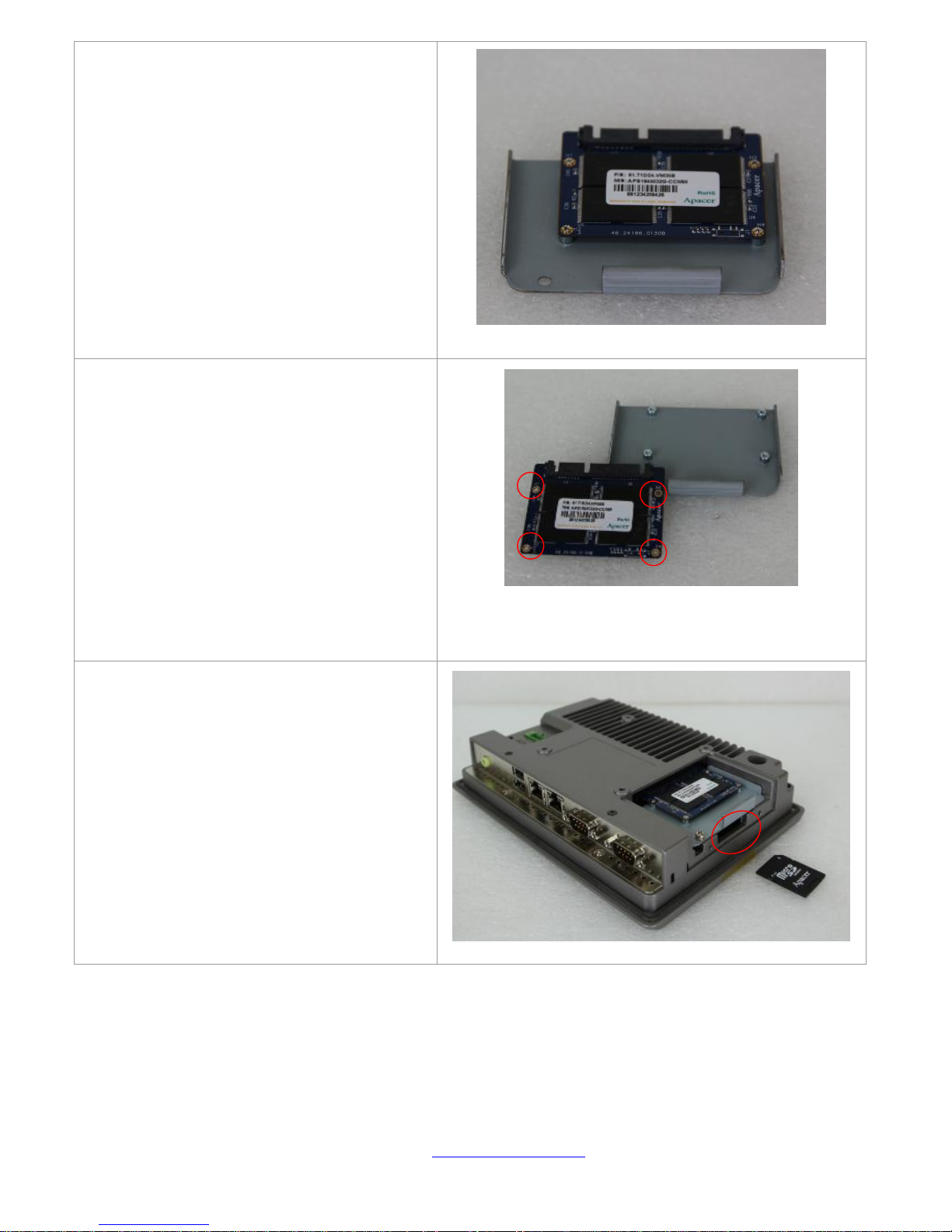
Step 1
There are 2 screws to deal with when
enclosing or removing the chassis. Gently
remove 2 screws.
Step 2
There is a SSD card in the bracket. Gently
remove the screw, then carefully pull SSD
card.
Page 12
NVHMI SERIES User Manual www.nemavision-ipc.com
12
Step 3
Take out SSD Card bracket.
Step 4.
You can replace SSD card by unscrewing 4
screws as shown in the picture.
Note: 4 screws are packed in the packing
list.
Step 5
There is a SD card hole in the side of the
machine. You can replace SD card from
there.
Page 13
NVHMI SERIES User Manual www.nemavision-ipc.com
13
Step 6.
Gently screw the screws.
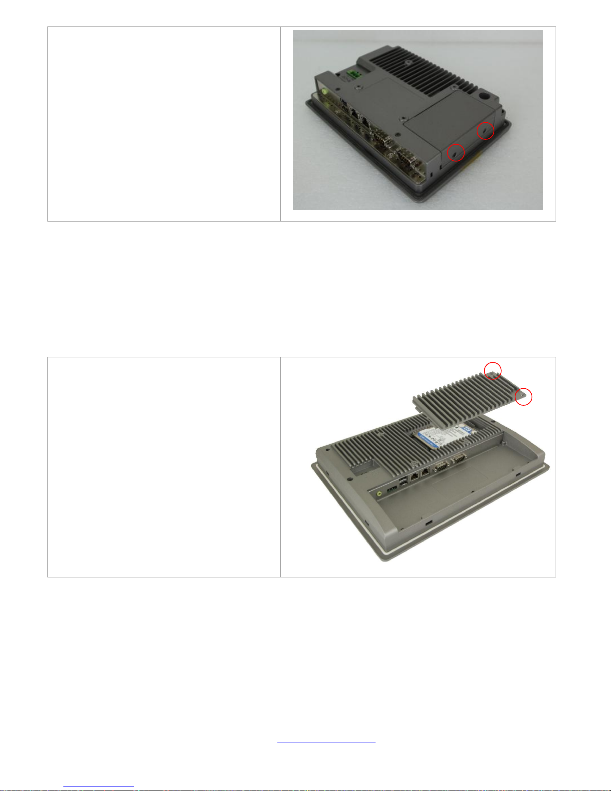
Installation of HDD(NVHMI-712 / NVHMI-715)
Step 1
There are 2 screws to deal with when
enclosing or removing the chassis. Gently
remove 2 screws.
Page 14
NVHMI SERIES User Manual www.nemavision-ipc.com
14
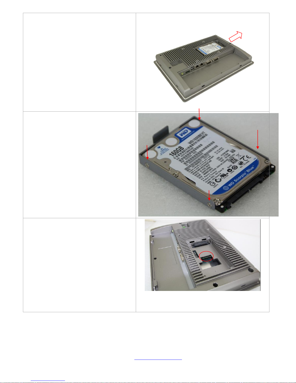
Step 2
You can put or remove HDD into the
machine by pulling the HDD bracket.
Step 3
You can remove HDD by unscrewing 4
screws in the HDD bracket.
Note: 4 screws are packed in the packing
package.
Step 4
There is a SD hole in the side of machine.
You can replace SD card from there.
Page 15
NVHMI SERIES User Manual www.nemavision-ipc.com
15
Chapter 2 Hardware
2.1 Mainboard
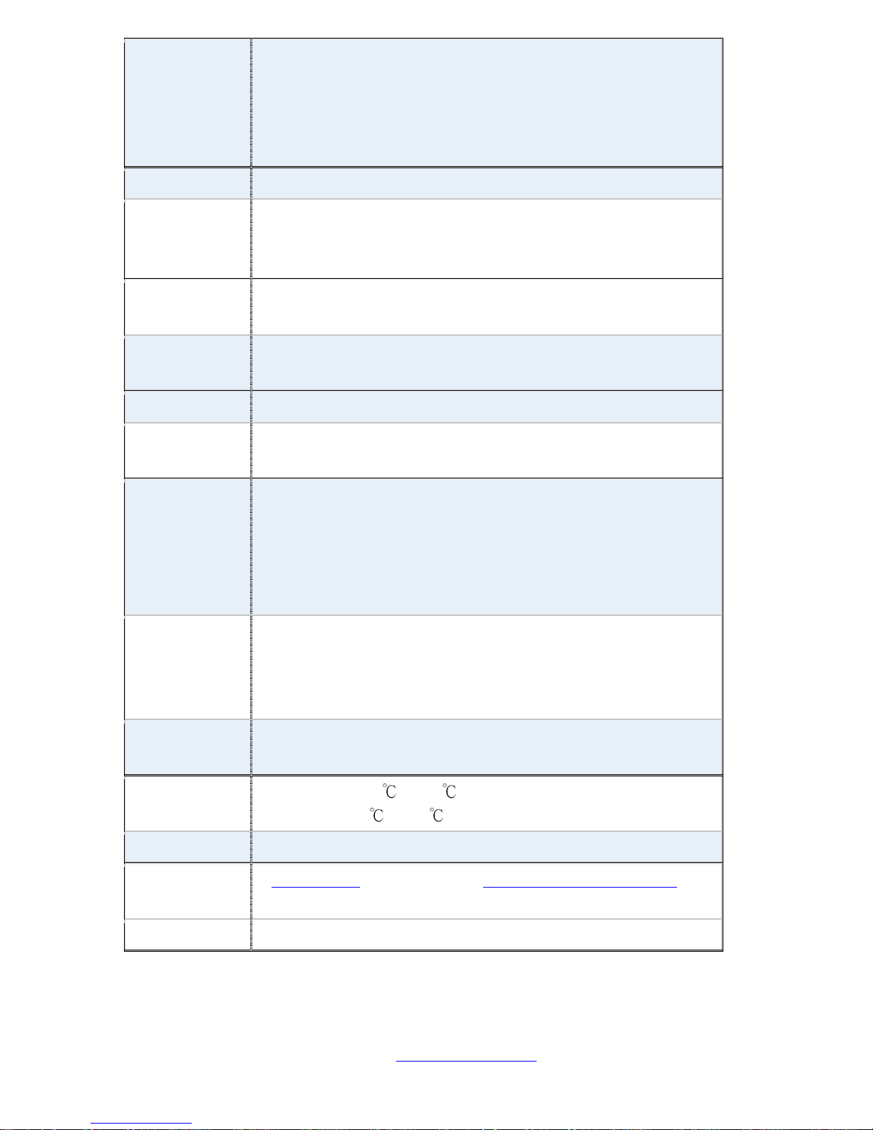
Specifications
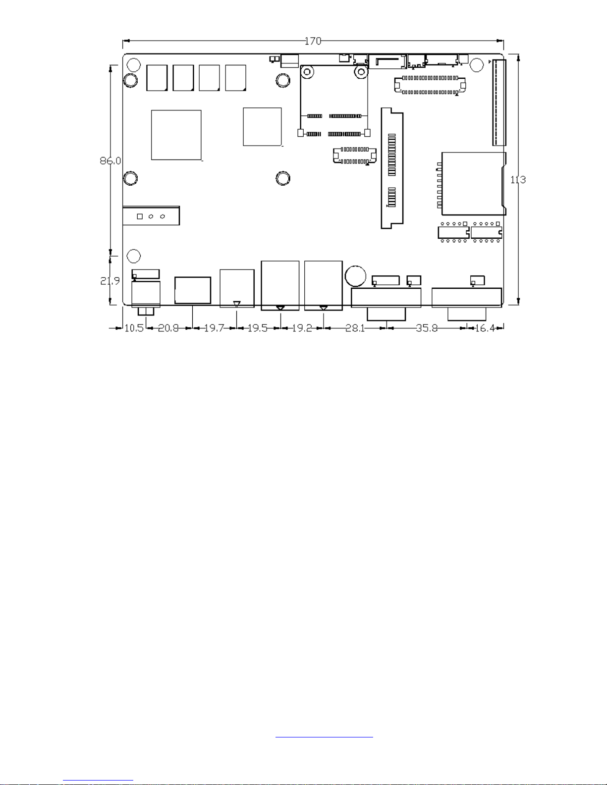
Board Size
170mm x 113mm
CPU Support
Intel Atom N2600 /1.60GHz
Chipset
Intel NM10 Express
Memory
Support
Onboard 2GB DDRIII SDRAM
Graphics
Integrated Intel GMA 3600 (N2600)
Display Mode
1 x CRT Port
1 x LVDS1 (18/24-bit single LVDS)
Support
Resolution
Up to 1920 x1200 for CRT
Up to 1366 x768 for LVDS1 (N2600)
Dual Display
CRT+LVDS1
Super I/O
Winbond W83627UHG-E
BIOS
AMIBIOS
Storage
1 x SATA Connector (7P)
1 x SATA Connector (7P+15P)
1 x SD Socket (USB to SD)
Ethernet
2 x PCIe GbE LAN by Realtek RTL8111E
USB
2 x USB 2.0 (type A)stack ports (USB4/USB5)
2 x USB 2.0 Pin header via CN3 (USB2/USB3)
2 x USB 2.0 Pin header via CN1 (USB0/USB1)
1 x USB 2.0 for MPCIE1 (USB7)
Mini-PCIe(USB7)
Serial
1 x RS-232/RS-422/RS-485, DB9 connector for external
(COM1)
pin 9 w/5V/12V/Ring select
1 x RS232 port, DB9 connector for external (COM2)
pin 9 w/5V/12V/Ring select
1 x RS422/485 header via CN2 (COM3)
2 x UART via CN3 (COM5,COM6)
Digital I/O
8-bit digital I/O Pin header via CN2
Page 16
NVHMI SERIES User Manual www.nemavision-ipc.com
16
4-bit digital Input
4-bit digital Output
4-bit digital I/O Pin header via CN3
2-bit digital Input
2-bit digital Output
Battery
Support CR2477 Li battery by 2-pin header
Audio
Realtek ALC662 HD audio codec
Line-in, Line-out, MIC via 2x6-pin header
Audio Line out in phone jack
Keyboard
/Mouse
1 x PS2 keyboard/mouse 1x6 box pin header via CN3
Expansion Bus
1 x mini-PCI-express slot
1 x PCI-express via CN3
Touch Ctrl
1 x Touch control header for TCH1 (COM4)
Power
Management
Wide Range DC 9~36V input
1 x 3-pin power input connector
Switches and
LED Indicators
1 x Power on/off switch via CN1
1 x Reset switch via CN1
1 x Power LED status via CN1
1 x HDD LED status via CN1
1 x Buzzer
External I/O
port
2 x COM Ports (COM1/COM2)
2 x USB 2.0 Ports (USB4/USB5)
2 x GbE LAN Ports
1 x Line out Audio phone jack
Watchdog
Timer
Software programmable 1 – 255 second by Super I/O
Temperature
Operating: -20 to 70
Storage: -40 to 85
Humidity
5% - 95%, non-condensing, operating
Power
Consumption
12V /0.95A (Intel Atom N2600 processor with 2GB DDR3
DRAM)
EMI/EMS
Meet CE/FCC class A
Page 17
NVHMI SERIES User Manual www.nemavision-ipc.com
17
(units :mm)
Figure 2.1: Mainboard Dimensions
Page 18
NVHMI SERIES User Manual www.nemavision-ipc.com
18
2.2 Installations
SBC-7106 is a 4" industrial motherboard developed on the basis of Intel Cedarview-M Processors and
NM10, which provides abundant peripheral interfaces to meet the needs of different customers. Also,
it features dual GbE ports, 3-COM ports and one Mini PCIE configuration, one VGA port, one HDMI
port, one LVDS interface. To satisfy the special needs of high-end customers, CN1 and CN2 and CN3
richer extension functions. The product is widely used in various sectors of industrial control.
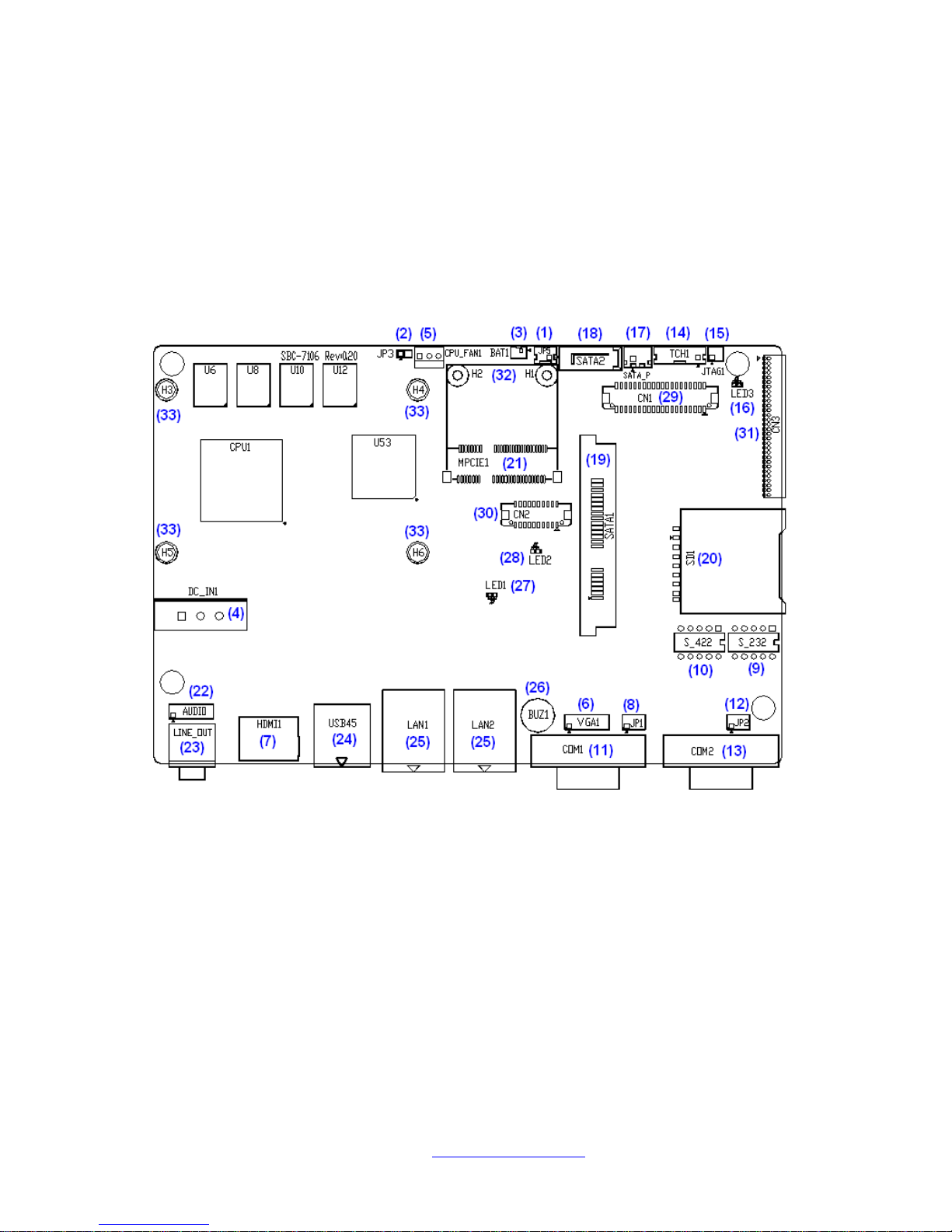
2.2.1 Jumpers Setting and Connectors
Board Top
Figure 2.2: Jumpers and Connectors Location_ Board Top
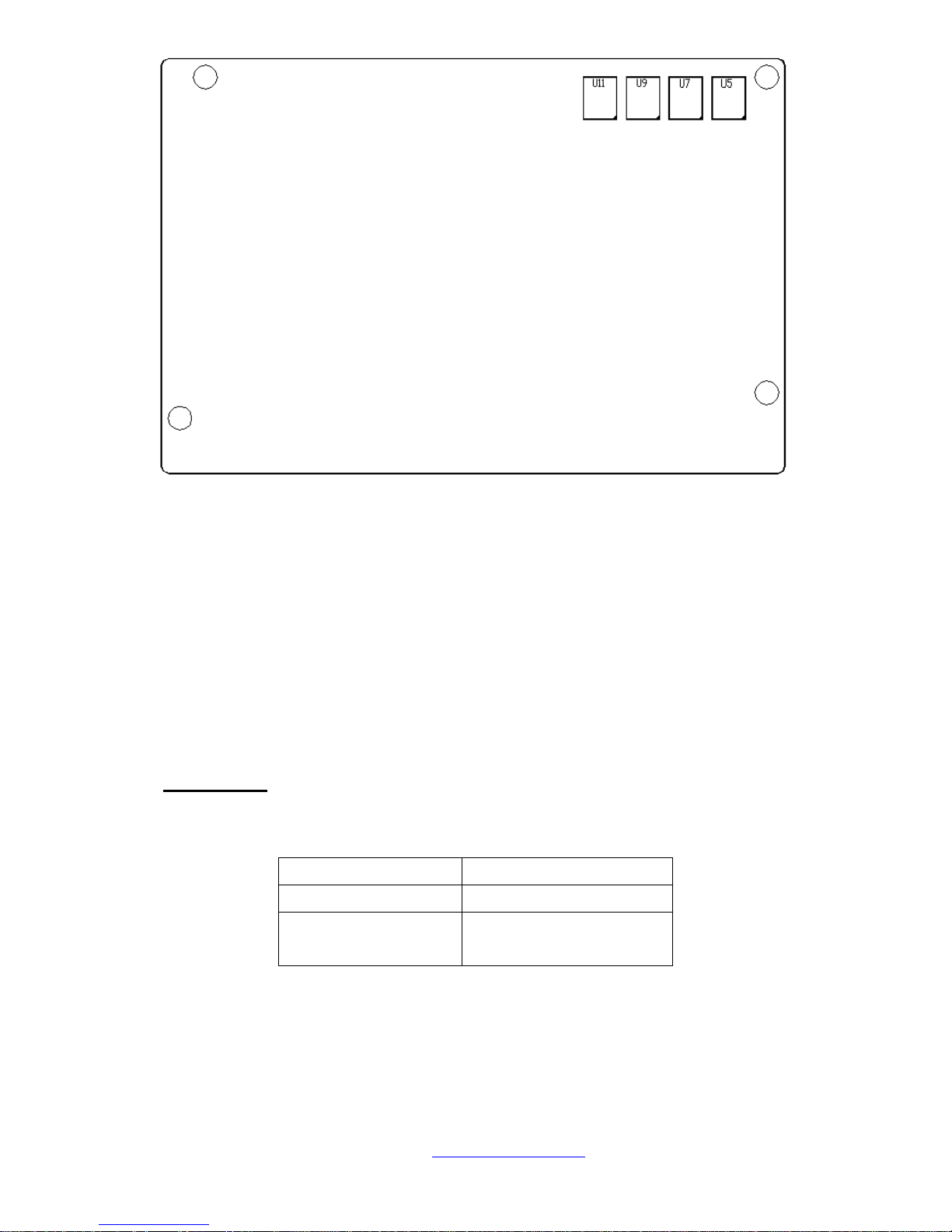
Board Bottom
Page 19
NVHMI SERIES User Manual www.nemavision-ipc.com
19
Figure 2.3: Jumpers and Connectors Location_ Board Bottom
2.3 Jumpers Setting and Connectors
1. JP5:
(2.0mm Pitch 1X2 box Pin Header),ATX Power and Auto Power on jumper setting.
JP5
Mode
Open
ATX Power
Close
Auto Power on
(Default)
Page 20

NVHMI SERIES User Manual www.nemavision-ipc.com
20
3. BAT1 :
(1.25mm Pitch 1X2 box Pin Header) 3.0V Li battery is embedded to provide power for
CMOS.
Pin#
Signal
Name
Pin1
VBAT
PIN2
Ground
4. DC_IN1:
(5.08mm Pitch 1x3 Pin Connector),DC9V~36V System power input connector
Pin#
Power Input
Pin1
DC+9V~32V
Pin2
Ground
Pin3
FG
6. VGA1:
(CRT 2.0mm Pitch 2X6 Pin Header), Video Graphic Array Port, Provide 2x6Pin cable to
VGA Port.
Signal Name
Pin#
Pin#
Signal Name
CRT_RED
1
2
Ground
CRT_GREEN
3
4
Ground
CRT_BLUE
5
6
Ground
CRT_H_SYN
C
7
8
CRT_DDCDAT
A
CRT_V_SYNC
9
10
CRT_DDCCL
K
Ground
11
12
Ground
Page 21

NVHMI SERIES User Manual www.nemavision-ipc.com
21
8. JP1:
(2.0mm Pitch 2x3 Pin Header),COM1 jumper setting, pin 1~6 are used to select signal
out of pin 9 of COM1 port.
JP1 Pin#
Function
Close 1-2
COM1 RI (Ring Indicator)
(default)
Close 3-4
COM1 Pin9=+5V
(option)
Close 5-6
COM1 Pin9=+12V
(option)
9. RS-232:
(Switch),COM1 jumper setting, it provides selectable RS232 or RS422 or RS485 serial
signal output.
Function
S_232 Pin#
RS232
(Default)
ON:
Pin1, Pin2, Pin3, Pin4
RS422
(option)
OFF:
Pin1, Pin2, Pin3, Pin4
RS485
(option)
OFF:
Pin1, Pin2, Pin3, Pin4
10. RS-422:
(Switch),COM1 setting, it provides selectable RS232 or RS422 or RS485 serial signal
output.
Function
RS_422 Pin#
RS232
(Default)
OFF: Pin1, Pin2, Pin3, Pin4
RS422
(option)
ON: Pin1, Pin2, Pin3, Pin4
RS485
(option)
ON: Pin1, Pin2, Pin3, Pin4
Note: Must keep the setting with BIOS setting.
Page 22
NVHMI SERIES User Manual www.nemavision-ipc.com
22
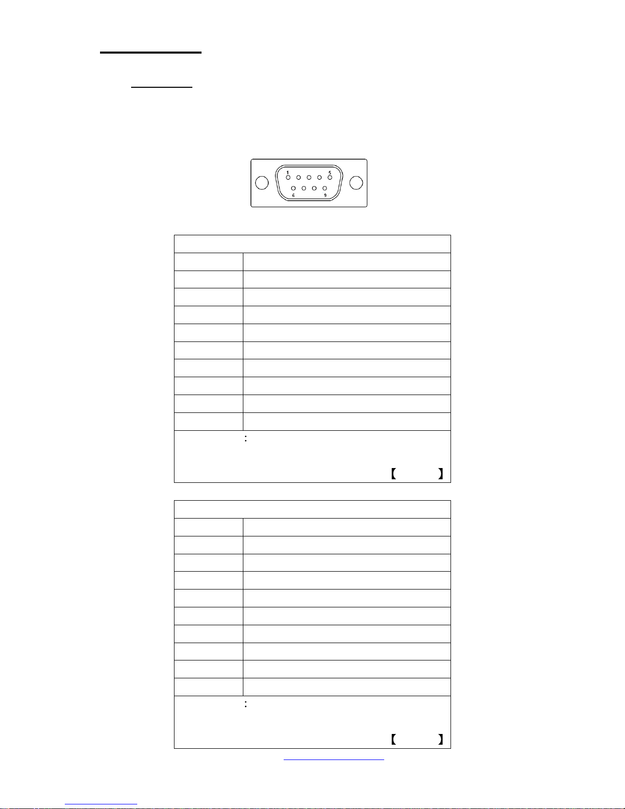
11. COM1:
(Type DB9),Rear serial port, standard DB9 Male serial port is provided to make a direct
connection to serial devices. COM1 port is controlled by pins No.1~6 of JP1,select
output Signal RI or 5V or 12V, For details, please refer to description of JP1 and S_232
and S_422 setting.
RS232 (Default):
Pin#
Signal Name
1
DCD# (Data Carrier Detect)
2
RXD (Received Data)
3
TXD (Transmit Data)
4
DTR (Data Terminal Ready)
5
Ground
6
DSR (Data Set Ready)
7
RTS (Request To Send)
8
CTS (Clear To Send)
9
JP1 select Setting (RI/5V/12V)
BIOS Setup
Advanced/W83627UHG Super IO
Configuration/Serial Port 1 Configuration RS-232
RS422 (option):
Pin#
Signal Name
1
422_RX+
2
422_RX-
3
422_TX-
4
422_TX+
5
Ground
6
NC 7 NC 8 NC 9 NC
BIOS Setup
Advanced/W83627UHG Super IO
Configuration/Serial Port 1 Configuration RS-422
Page 23

NVHMI SERIES User Manual www.nemavision-ipc.com
23
RS485 (option):
Pin#
Signal Name
1
NC 2 NC 3 485-
4
485+
5
Ground
6
NC 7 NC 8 NC 9 NC
BIOS Setup
Advanced/W83627UHG Super IO
Configuration/Serial Port 1 Configuration RS-485
12 JP2:
(2.0mm Pitch 2x3 Pin Header), COM2 jumper setting, pin 1~6 are used to select signal
out of pin 9 of COM2 port.
JP2 Pin#
Function
Close 1-2
COM1 RI (Ring Indicator)
(default)
Close 3-4
COM1 Pin9=+5V
(option)
Close 5-6
COM1 Pin9=+12V
(option)
Page 24
NVHMI SERIES User Manual www.nemavision-ipc.com
24
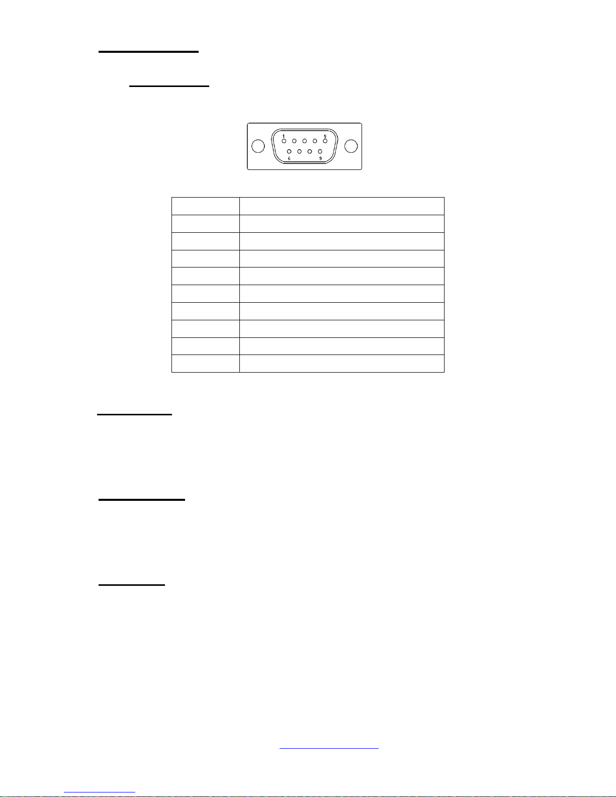
13. COM2:
(Type DB9),Rear serial port, standard DB9 Male serial port is provided to make a
direct connection to serial devices.
Pin#
Signal Name
1
DCD# (Data Carrier Detect)
2
RXD (Received Data)
3
TXD (Transmit Data)
4
DTR (Data Terminal Ready)
5
Ground
6
DSR (Data Set Ready)
7
RTS (Request To Send)
8
CTS (Clear To Send)
9
RI (Ring Indicator)
16. LED3:
LED STATUS. Green LED for Touch Power status.
19 SATA1:
(SATA 7Pin+15Pin), SATA Connectors, one SATA connectors are provided, with transfer
speed up to 3.0Gb/s.
20 SD1:
(SD card socket),Secure Digital Memory Card socket.
Page 25
NVHMI SERIES User Manual www.nemavision-ipc.com
25
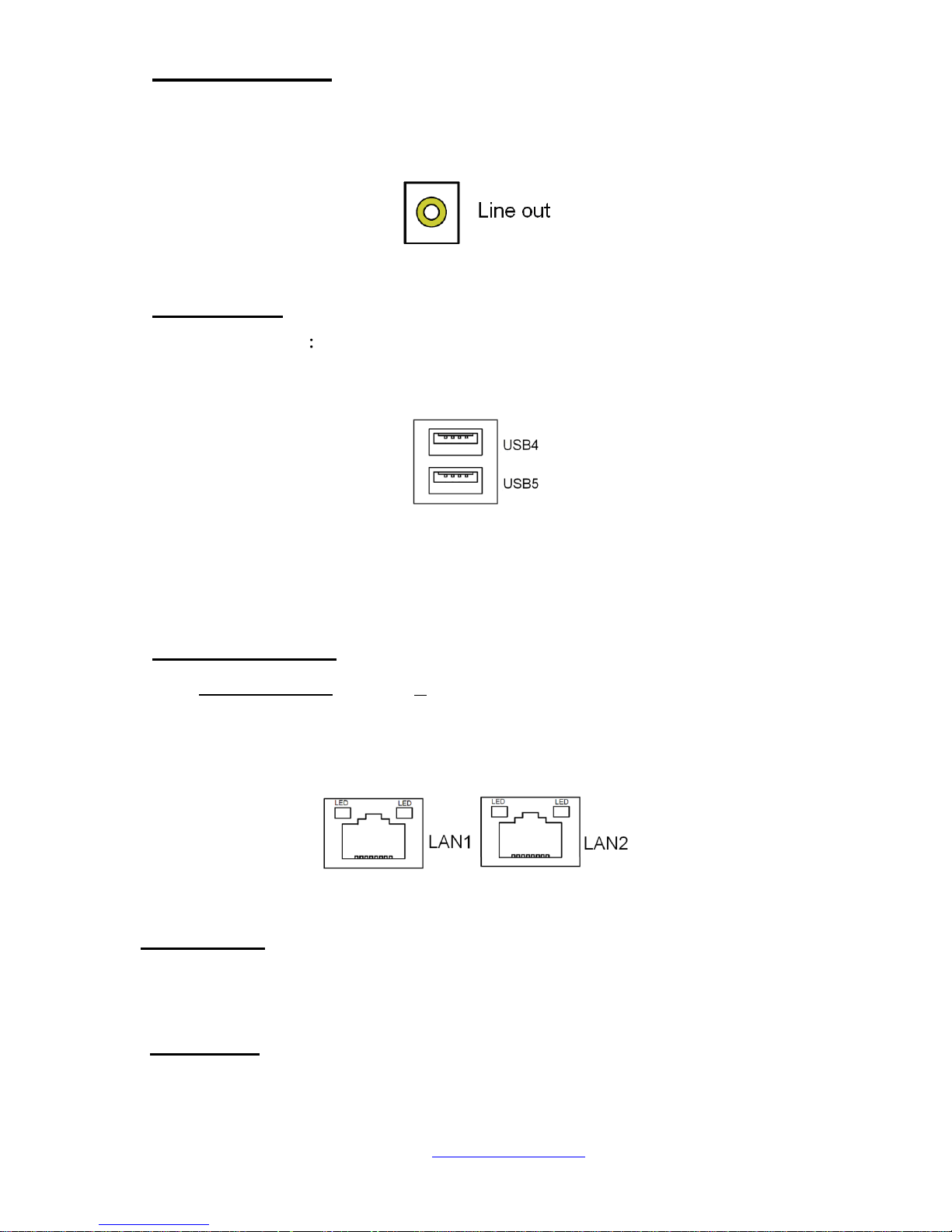
23. LINE_OUT:
(Diameter 3.5mm Jack), HD Audio port, An onboard Realtek ALC662 codec is used to
provide high quality audio I/O ports. Line Out can be connected to a headphone or
amplifier.
24. USB45:
USB4/USB5 (Double stack USB type A), Rear USB connector, it provides up to 4
USB2.0 ports, High-speed USB 2.0 allows data transfers up to480 Mb/s ,support USB
full-speed and low-speed signaling.
Each USB Type A Receptacle (2 Ports) Current limited value is 1.5A.
If the external USB device current exceeds 1.5A, please separate connectors
into different Receptacle.
25. LAN1/LAN2:
LAN1/LAN2: (RJ45 Connector), Rear LAN port, Two standard 10/100/1000M RJ-45
Ethernet ports are provided. Used Realtek RTL8111E chipset, LINK LED (green) and
ACTIVE LED (yellow) respectively located at the left-hand and right-hand side of the
Ethernet port indicate the activity and transmission state of LAN.
26. BUZ1:
Onboard buzzer.
27 LED1:
LED STATUS. Green LED for Motherboard Power status.
Page 26

NVHMI SERIES User Manual www.nemavision-ipc.com
26
28. LED2:
LED STATUS. Green LED for Motherboard Standby Power Good status.
31. CN3:
(1.27mm Pitch 2X30 Pin Header), For expand output connector, It provides four GPIO,
Two USB 2.0,one PS/2 mouse one PS/2 keyboard,two uart,one PCIe x1,one SMbus.
Function
Signal Name
Pin#
Pin#
Signal Name
Function
5V_S5_USB
1 2 5V_S5_USB
5V_S5_USB
3 4 5V_S5_USB
USB23_OC
5
6
CLKREQPSON_ATX-
USB2
USB2_N
7 8 USB2_P
USB2
USB3
USB3_N
9
10
USB3_P
USB3
Ground
11
12
Ground
PS/2 MS
PS2_MSCLK
13
14
PS2_MSDATA
PS/2 MS
PS/2 KB
PS2_KBCLK
15
16
PS2_KBDATA
PS/2 KB
COM6
(UART)
COM6_RI
17
18
COM6_DCD-
COM6
(UART)
COM6_TXD
19
20
COM6_RXD
COM6_DTR
21
22
RICOM6_RTS
-
COM6_DSR
23
24
COM6_CTS-
Ground
25
26
Ground
COM5
(UART)
COM5_RI
27
28
COM5_DCD-
COM5
(UART)
COM5_TXD
29
30
COM5_RXD
COM5_DTR
31
32
DSRCOM5_RTS-
COM5_DSR
33
34
DTRCOM5_CTS-
GPIO24
ICH_GPIO24
35
36
ICH_GPIO13
GPIO13
GPIO26
ICH_GPIO26
37
38
ICH_GPIO27
GPIO27
Ground
39
40
Ground
PCIE
PE1_TX_N0
41
42
PE1_TX_P0
PCIE
PE1_RX_N0
43
44
PE1_RX_P0
Ground
45
46
Ground
CLK_100M_PE1_N
47
48
CLK_100M_PE1_P
PM_PCIE_WAKE
49
50
PLTRST_BUF-
SMBUS
SMB_CLK_S
5
51
52
SMB_DATA_S
5
SMBUS
PCIE
PE1_CLKRE
Q
53
54
Ground
PCIE
3P3V_S5
55
56
3P3V_S5
Page 27

NVHMI SERIES User Manual www.nemavision-ipc.com
27
3P3V_S5
57
58
3P3V_S5
12V
12V_S0
59
60
12V_S0
12V
Page 28

NVHMI SERIES User Manual www.nemavision-ipc.com
28
3 BIOS Setup Description
3.1 Operations after POST Screen
After CMOS discharge or BIOS flashing operation,.Press [Delete] key to enter CMOS Setup.
Version 2.15.1226. Copyright (C) 2012 American Megatrends, Inc.
BIOS Date: 12/17/2012 02:22:46 Ver: 7106V002
Press DEL or F2 to enter setup
A3
After optimizing and exiting CMOS Setup, the POST screen displayed for the first time is as follows and
includes basic information on BIOS, CPU, memory, and storage devices.
Page 29
NVHMI SERIES User Manual www.nemavision-ipc.com
29
3.2 BIOS SETUP UTILITY
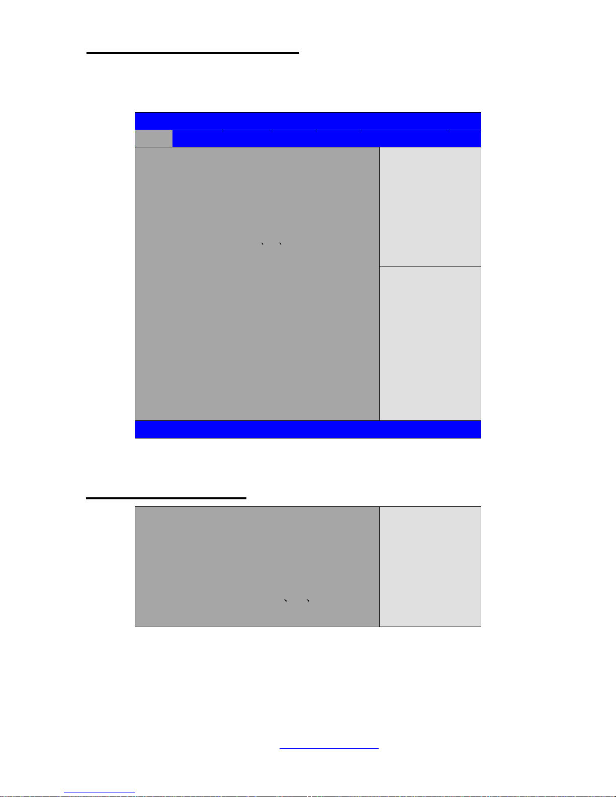
Press [Delete] key to enter BIOS Setup utility during POST, and then a main menu containing
system summary information will appear.
Aptio Setup Utility – Copyright (C) 2012 American Megatrends, Inc.
Main
Advanced
Chipset
Boot
Security
Save & Exit
BIOS Information
BIOS Vendor American Megatrends
Core Version 4.6.5.3
Compliancy UEFI 2.3; PI 1.2
Project Version 7106V002
Build Date and Time 12 17 2012 03:22:46
►Intel RC Version
System Language [English]
System Date [Sun 01/01/2012]
System Time [00:00:08]
Access Level Administrator
Intel Reference Code
Version
→←: Select Screen
↑↓ : Select Item
Enter: Select
+/- : Charge Opt.
F1 : General Help
F2: Previous Values
F3:Optimized Defaults
F4:Save and Exit
ESC Exit
Version 2.15.1226. Copyright (C) 2012 American Megatrends , Inc.
3.3 Main Settings
BIOS Information
BIOS Vendor American Megatrends
Core Version 4.6.5.3
Compliancy UEFI 2.3; PI 1.2
Project Version 7106V002
Build Date and Time 12 17 2012 03:22:46
►Intel RC Version
Intel Reference Code
Version
Page 30

NVHMI SERIES User Manual www.nemavision-ipc.com
30
System Language [English]
System Date [Sun 01/01/2012]
System Time [00:00:08]
Access Level Administrator
→←: Select Screen
↑↓ : Select Item
Enter: Select
+/- : Charge Opt.
F1 : General Help
F2: Previous Values
F3:Optimized Defaults
F4:Save and Exit
ESC Exit
Version 2.15.1226. Copyright (C) 2012 American Megatrends , Inc.
System Time:
Set the system time, the time format is:
Hour : 0 to 23
Minute : 0 to 59
Second : 0 to 59
System Date:
Set the system date, the date format is:
Day: Note that the ‘Day’ automatically changes when you set the date.
Month: 01 to 12
Date: 01 to 31
Year: 1998 to 2099
Page 31
NVHMI SERIES User Manual www.nemavision-ipc.com
31
3.4 Advanced Settings
Aptio Setup Utility – Copyright (C) 2012 American Megatrends, Inc.
Main
Advanced
Chipset
Boot
Security
Save & Exit
►PCI Subsystem Settings
►ACPI Settings
►CPU Configuration
►Thermal Configuration
►IDE Configuration
►USB Configuration
►W83627UHG Super IO Configuration
►W83627UHG HW Monitor
►Serial Port Console Redirection
►PPM Configuration
PCI,PCI-X and PCI
Express Settings
→←: Select Screen
↑↓ : Select Item
Enter: Select
+/- : Charge Opt.
F1 : General Help
F2: Previous Values
F3:Optimized Defaults
F4:Save and Exit
ESC Exit
Version 2.15.1226. Copyright (C) 2012 American Megatrends , Inc.
3.4.1 PCI Subsystem Settings
PCI Bus Driver Versio V2.05.02
PCI Common Settings:
PCI Latency Timer:
[32 PCI Bus Clocks]
[64 PCI Bus Clocks]
[96 PCI Bus Clocks]
[128 PCI Bus Clocks]
[160 PCI Bus Clocks]
[192 PCI Bus Clocks]
[224 PCI Bus Clocks]
[248 PCI Bus Clocks]
VGA Palette Snoop:
[Disabled]
[Enabled]
PERR# Generation:
Page 32

NVHMI SERIES User Manual www.nemavision-ipc.com
32
[Disabled]
[Enabled]
SERR# Generation:
[Disabled]
[Enabled]
3.4.2 ACPI Settings
Enable ACPI Auto Conf:
[Disabled]
[Enabled]
Enable Hibernation:
[Enabled]
[Disabled]
ACPI Sleep State:
[Both S1 and S3 available for OS to choose from ]
[Suspend Disabled]
[S1 only(CPU Stop Clock) ]
[S3 only (Suspend to RAM) ]
Lock Legacy Resources:
[Disabled]
[Enabled]
S3 Video Repost:
[Disabled]
[Enabled]
3.4.3 CPU Configuration
Processor Type Intel(R) Atom(TM) CPU N2600
EMT64 Not Supported
Processor Speed 1600 MHz
System Bus Speed 400MHz
Ratio Status 16
Actual Ratio 16
System Bus Speed 400 MHz
Processor Stepping 30661
Microcode Revision 269
Page 33

NVHMI SERIES User Manual www.nemavision-ipc.com
33
L1 Cache RAM 2x56 k
L2 Cache RAM 2x512 k
Processor Core Dual
Hyper-Threading Supported
Hyper-Threading:
[Enabled]
[Disabled]
Execute Disable Bit:
[Enabled]
[Disabled]
Limit CPUID Maximum:
[Disabled]
[Enabled]
3.4.4 Thermal Configuration
CPU Thermal Configuration
DTS SMM
[Disabled]
[Enabled]
Platform Thermal Configuration
Critical Trip Point [POR]
Active Trip Point Lo [55 C]
Active Trip Point Hi [71C]
Passive Trip Point [95]
Passive TC1 Value 1
Passive TC2 Value 5
Passive TSP Value 10
3.4.5 IDE Configuration
SATA Port0 Not Present
SATA Port1 Not Present
SATA Controller(S):
[Enabled]
[Disabled]
Configure SATA as:
[IDE]
Page 34

NVHMI SERIES User Manual www.nemavision-ipc.com
34
[AHCI]
Misc Configuration for hard disk
3.4.6 USB Configuration
USB Configuration
USB Devices:
1 Drive 1 keyboard
Legacy USB Support:
[Enabled]
[Disabled]
EHCI Hand-off:
[Disabled]
[Enabled]
USB hardware delays a
USB transfer time-out:
[20 sec]
[10 sec]
[5 sec]
[1 sec]
Device reset time-out:
[20 sec]
[10 sec]
[30 sec]
[40 sec]
Device power-up delay
[Auto]
[Manual]
Mass Storage Devices
Multiplecard Reader 1
[Auto]
[Floppy]
[Forced FDD]
[Hard Disk]
[CD-ROM]
3.4.7 W83627UHG Super IO Configuration
W83627UHG Super IO ch W83627UHG
Serial Port 1 Configuration
UART Mode Selection
[RS-232]
Page 35

NVHMI SERIES User Manual www.nemavision-ipc.com
35
[RS-485]
[RS-422]
Serial Port 2 Configuration
Serial Port 3 Configuration
UART Mode Selection
[RS-485]
[RS-422]
Serial Port 4 Configuration
Serial Port 5 Configuration
Serial Port 6 Configuration
Power Failure
[Keep last state]
[Always off]
[Always on]
3.4.8 W83627UHG HW Monitor
PC Health Status
System temperature1 : +38
System Speed : N/A
VCORE : +0.968 V
+12V : +12.302 V
+3.3V : +3.320 V
+1.5V : +1.528 V
AVCC : +5.203 V
VCC5V : +5.216 V
VSB5 : +5.203 V
VBAT : +3.334 V
3.4.9 Serial Port Console Redirection
COM0
Console Redirection
[Enabled]
[Disabled]
Console Redirection Settings
Serial Port for Out-of-Band Management/
Windows Emergency Management Services (EMS)
Console Redirection
Page 36

NVHMI SERIES User Manual www.nemavision-ipc.com
36
[Disabled]
[Enabled]
Console Redirection Settings
3.4.10 PPM Configuration
PPM Configuration
EIST:
[Enabled]
[Disabled]
CPU C state Report
[Enabled]
[Disabled]
Enhanced C state
[Enabled]
[Disabled]
CPU Hard C4E
[Enabled]
[Disabled]
CPU C6 state
[Enabled]
[Disabled]
C4 Exit Timing
[Fast]
[Default]
[Slow]
C-state POPDOWN
[Enabled]
[Disabled]
C-state POPUP
[Enabled]
[Disabled]
Page 37
NVHMI SERIES User Manual www.nemavision-ipc.com
37
3.5 Chipset Settings
Aptio Setup Utility – Copyright (C) 2012 American Megatrends, Inc.
Main
Advanced
Chipset
Boot
Security
Save & Exit
►Host Bridge
►South Bridge
Host Bridge Parameters
→←: Select Screen
↑↓ : Select Item
Enter: Select
+/- : Charge Opt.
F1 : General Help
F2: Previous Values
F3:Optimized Defaults
F4:Save and Exit
ESC Exit
Version 2.15.1226. Copyright (C) 2012 American Megatrends , Inc.
3.5.1 Host Bridge
►Memory Frequency and Timing
►Intel IGD Configuration
******* Memory Information *******
Memory Frequency 800 MHz(DDR3)
Tot al Memory 2048 MB
DIMM#0 Not Present
DIMM#1 2048 MB
Memory Frequency and Timing
MRC Fast Boot
[Enabled]
[Disabled]
Max TOLUD
[Dynamic]
[1GB]
[1.25GB]
Page 38

NVHMI SERIES User Manual www.nemavision-ipc.com
38
[1.5GB]
[1.75GB]
[2GB]
[2.25GB]
[2.5GB]
[2.75GB]
[3GB]
[3.25GB]
Intel IGD Configuration
IGFX – Boot Type
[VBIOS Default]
[VGA]
[LVDS]
[VGA + LVDS]
LCD Panel Type
[VBIOS Default]
[640x480 18bit]
[800x480 18bit]
[800x600 18bit]
[1024x600 18bit ]
[1024x768 18bit ]
[1280x768 18bit ]
[1280x800 18bit ]
[1280x1024 18bit]
[1366x768 18bit]
[1024x768 24bit]
[1280x768 24bit]
[1280x800 24bit]
[1280x1024 24bit]
Panel Scaling
[Auto]
[Force Scaling]
[off]
[Maintain Aspect Ratio]
Active LFP
[LVDS]
[No LVDS]
[EDP]
Page 39

NVHMI SERIES User Manual www.nemavision-ipc.com
39
IGD Clock Source
[External Clock]
[Internal Clock]
Fixed Graphics Memory
[128MB]
[256MB]
ALS Support
[Disabled]
[Enabled]
Back light Control
[DC]
[PWM]
Back light Logic
[Positive]
[Negative]
Back light Control Lev
[Auto]
[Disabled]
[Level 8]
[Level 1]
[Level 2]
[Level 3]
[Level 4]
[Level 5]
[Level 6]
[Level 7]
[Level 8]
[Level 9]
[Level 10]
[Level 11]
[Level 12]
[Level 13]
[Level 14]
[Level 15]
Page 40

NVHMI SERIES User Manual www.nemavision-ipc.com
40
3.5.2 South Bridge
TPT Devices
PCI Express Root Port 0
PCI Express Root Port 1
PCI Express Root Port 2
PCI Express Root Port 3
DMI Link ASPM Control
[Enabled]
[Disabled]
PCI-Exp. High Priorit
[Disabled]
[Enabled]
High Precision Event Timer Configuration
High Precision Timer
[Enabled]
[Disabled]
SLP_S4 Assertion Widt
[1-2 Seconds]
[2-3 Seconds]
[3-4 Seconds]
[4-5 Seconds]
Restore AC Power Loss
[Last State]
[Power off]
[Power on]
Page 41
NVHMI SERIES User Manual www.nemavision-ipc.com
41
3.6 Boot Settings
Aptio Setup Utility – Copyright (C) 2012 American Megatrends, Inc.
Main
Advanced
Chipset
Boot
Security
Save & Exit
Boot Configuration
Setup Prompt Timeout 1
Bootup Numlock State [On]
Quiet Boot [Disabled]
Fast Boot [Enabled]
Skip USB [Disabled]
Skip PS2 [Disabled]
CSM16 Module Version 07.69
Gatea20 Active [Upon Request]
Option ROM Messages [Force BIOS]
Interrupt 19 Capture [Enabled]
Driver Option Priorities
Boot Option Priorities
Boot Option Priorities
Boot Option #1 [SATA PM: Hitachi…]
Boot Option #2 […]
Hard Drive BBS Priorities
►CSM Parameters
Number of seconds to
Wait for setup
Activation key.
65535(0xFFFF)means
Indef inite waiting.
→←: Select Screen
↑↓ : Select Item
Enter: Select
+/- : Charge Opt.
F1 : General Help
F2: Previous Values
F3:Optimized Defaults
F4:Save and Exit
ESC Exit
Version 2.15.1226. Copyright (C) 2012 American Megatrends , Inc.
Setup Prompt Timeout [1]
Bootup Numlock State
[On]
[off]
Quiet Boot
[Disabled]
Page 42

NVHMI SERIES User Manual www.nemavision-ipc.com
42
[Enabled]
Fast Boot
[Enabled]
[Disabled]
Skip VGA
[Enabled]
[Disabled]
Skip USB
[Disabled]
[Enabled]
Skip PS2
[Disabled]
[Enabled]
CSM16 Module Version 07.69
Gatea20 Active
[Upon Request]
[Always]
Option ROM Messages
[Force BIOS]
[Keep Current]
Interrupt 19 Capture
[Immediate]
[Postponed]
Boot Option #1
Boot Option #2
……
Sets the system boot order
Hard Drive BBS Priorities [SATA PM:*** … ]
Boot Option #1
SATA PM:***…
******
Disabled
CSM Parameters
Launch CSM
[Always]
Page 43

NVHMI SERIES User Manual www.nemavision-ipc.com
43
[Never]
Boot option filter
[UEFI and Legacy]
[Legacy only]
[UEFI only]
Launch PXE OpROM poli
[Do not Launch]
[UEFI only]
[Legacy only]
Launch Storage OpROM
[Legacy only]
[Do not Launch]
[UEFI only]
Launch Video OpROM po
[Do not Launch]
[UEFI only]
[Legacy only]
Other PCI device ROM
[UEFI OpROM]
[Legacy OpROM]
Page 44
NVHMI SERIES User Manual www.nemavision-ipc.com
44
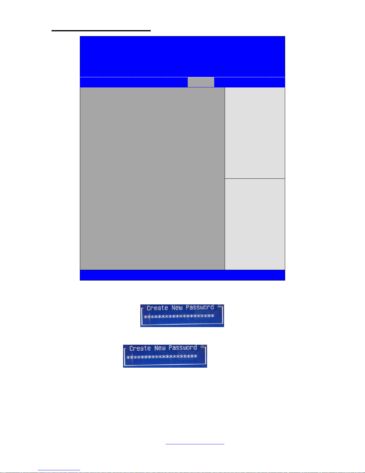
3.7 Security Settings
Aptio Setup Utility – Copyright (C) 2012
American Megatrends, Inc.
Main
Advanced
Chipset
Boot
Security
Save & Exit
Password Description
If ONLY the Administrator’s password is set,
Then this only limits access to Setup and is
Only asked for when entering Setup.
If ONLY the User’s password is set, then this
Is a power on password and must be entered to
Is a power on password and must be entered to
Boot or enter Setup. In Setup the User will
Have Administrator rights.
The password length must be
In the following range:
Minimum length 3
Maximum length 20
Administrator Password
User Password
Set Administrator
Password
→←: Select Screen
↑↓ : Select Item
Enter: Select
+/- : Charge Opt.
F1 : General Help
F2: Previous Values
F3:Optimized Defaults
F4:Save and Exit
ESC Exit
Version 2.15.1226. Copyright (C) 2012 American Megatrends , Inc.
6.4.1 Administrator Password
6.4.2 User Password
Type the password with up to 20 characters and then press Enter key. This will clear all
previously typed CMOS passwords. You will be requested to confirm the password. Type the
password again and press Enter key. You may press Esc key to abandon password entry
operation.
To clear the password, just press Enter key when password input window pops up. A
confirmation message will be shown on the screen as to whether the password will be disabled.
Page 45
NVHMI SERIES User Manual www.nemavision-ipc.com
45
You will have direct access to BIOS setup without typing any password after system reboot once
the password is disabled.
Once the password feature is used, you will be requested to type the password each time you
enter BIOS setup. This will prevent unauthorized persons from changing your system
configurations.
Also, the feature is capable of requesting users to enter the password prior to system boot to
control unauthorized access to your computer. Users may enable the feature in Security Option
of Advanced BIOS Features. If Security Option is set to System, you will be requested to enter
the password before system boot and when entering BIOS setup; if Security Option is set to
Setup, you will be requested for password for entering BIOS setup.
3.8 Save and Exist Settings
BIOS SETUP UTILITY
Main
Advanced
PCIPnP
Boot
Security
Chipset
Exit
Advanced Chipset Settings
Configure North Bridge
feature
← Select Screen
↑↓ Select Item
Enter Go to sub screen
F1 General Help
F10 Save and Exit
ESC Exit
WARNING: Setting wrong values in below
sections
may cause system to malfunction
► North Bridge Configuration
► South Bridge Configuration
V02.61 © Copyright 1985-2006 American Mega trends , Inc.
Note: Due to limited address length of BIOS, only a portion of panel parameters are listed in
BIOS Setup. If the connected panel is not included in the parameter list, display
problem will occur. In this case, Please do not change BIOS setup.
Page 46

NVHMI SERIES User Manual www.nemavision-ipc.com
46
3.8.1 North Bridge Configuration
BIOS SETUP UTILITY
Chipset
North Bridge Chipset Configuration
ENABLE: Allow
Remapping of
Over lapped PCI Memory
Above the total
Physical memory
DISABLE: Do not allow
remapping of memory
← Select Screen
↑↓ Select Item
+- Charge Field
F1 General Help
F10 Save and Exit
ESC Exit
Memory Remap Feature
[Enabled]
PCI MMIO Allocation: 4Gb To 3072MB
Memory Hole
[Disabled]
Initate Graphic Adapter [PCI/IGD]
IGD Graphics Mode Select
[Enabled ,64MB]
IGD GTI Graphic smemory size [No VT
mode,2MB]
PEG Port Configuration
► Video Function Configuration
V02.61 © Copyright 1985-2006 American Mega trends , Inc.
Memory Remap Feature:
[Enabled]
[Disabled]
Memory Hole:
[Disabled]
[15MB-16MB]
Initate Graphic Adapter:
Select which graphics controller to use as the primary boot device.
[IGD]
[PCI/IGD]
IGD Graphics Mode Select:
[Enabled, 64MB]
[Disabled]
Page 47

NVHMI SERIES User Manual www.nemavision-ipc.com
47
[Enabled, 32MB]
[Enabled, 128MB]
Video Function Configuration:
BIOS SETUP UTILITY
Chipset
Video Function Configuration
Options
Fixed Mode
DVMT Mode
← Select Screen
↑↓ Select Item
+- Charge option
F1 General Help
F10 Save and Exit
ESC Exit
DVMT Mode Select [DVMT
Mode]
DVMT/FIXED Memory
[256MB]
Boot Display Device
[VBIOS-Default]
Flat Panel Type [1024x768
18bit 1c]
Backlight Control Support
[VBIOS-Default]
Backlight Control Level [Level 5]
Backlight Control Mode [DC]
Backlight Image Adaptation
[VBIOS-Default]
V02.61 © Copyright 1985-2006 American Mega trends , Inc.
DVMT Mode Select:
[DVMT Mode]
[FIXED Mode]
DVMT/FIXED Memory Size:
[256MB]
[128MB]
[Maximum DVMT]
Boot Display Device:
[BIOS-Default]
[CRT]
Page 48

NVHMI SERIES User Manual www.nemavision-ipc.com
48
[LVDS]
[CRT + LVDS]
Flat Panel Type:
[1024x 768 18bit 1ch]
[640x480 18bit 1ch]
[800x600 18bit 1ch]
[1280x800 18bit 1ch]
[1366x768 18bit 1ch]
[1024x 768 24bit 2ch]
[1440x900 24bit 2ch]
[1600x900 24bit 2ch]
[1680x1050 24bit 2ch]
[1920x1080 24bit 2ch]
Backlight Control Support
[VBIOS-Default]
[Both BLC & BIA Disabled]
[BLC Enabled]
Backlight Control Control:
[Level5]
[Level0]
[Level1]
[Level2]
[Level3]
[Level4]
[Level6]
[Level7]
Note: Panel support PWM Function.
Backlight Control Mode:
[DC]
[PWM]
Backlight Image Adaptation:
[VBIOS-Default]
[BIA Disabled]
[BIA Enabled at Level1]
[BIA Enabled at Level2]
Page 49
NVHMI SERIES User Manual www.nemavision-ipc.com
49
[BIA Enabled at Level3]
[BIA Enabled at Level4]
[BIA Enabled at Level5]
3.8.2 South Bridge Configuration:
Aptio Setup Utility – Copyright (C) 2012 American Megatrends, Inc.
Main
Advanced
Chipset
Boot
Security
Save & Exit
Save Changes and Exit
Discard Changes and Exit
Save Changes and Reset
Discard Changes and Reset
Save Options
Save Changes
Discard Changes
Restore Defaults
Save user Defaults
Restore user Defaults
Boot Override
MultipleCard Reader 1.00
SATA PM:*** …
Launch EFI Shell from filesystem device
Exit system setup after
Saving the changes.
→←: Select Screen
↑↓ : Select Item
Enter: Select
+/- : Charge Opt.
F1 : General Help
F2: Previous Values
F3:Optimized Defaults
F4:Save and Exit
ESC Exit
Version 2.15.1226. Copyright (C) 2012 American Megatrends , Inc.
Save Changes and Exit
Save & Exit Setup save Configuration and exit ?
[Yes]
[No]
Discard Changes and Ext
Exit Without Saving Quit without saving?
[Yes]
[No]
Save Changes and Reset
Save & reset Save Configuration and reset?
[Yes]
Page 50

NVHMI SERIES User Manual www.nemavision-ipc.com
50
[No]
Discard Changes and Reset
Reset Without Saving Reset without saving?
[Yes]
[No]
Save Changes
Save Setup Values Save configuration?
[Yes]
[No]
Discard Changes
Load Previous Values Load Previous Values?
[Yes]
[No]
Restore Defaults
Load Optimized Defaults Load optimized Defaults?
[Yes]
[No]
Save user Defaults
Save Values as User Defaults Save configuration?
[Yes]
[No]
Restore user Defaults
Restore User Defaults Restore User Defaults?
[Yes]
[No]
Launch EFI Shell from filesystem device
WARNING Not Found
[ok]
Page 51

NVHMI SERIES User Manual www.nemavision-ipc.com
51
3.9 Exit Options
BIOS SETUP UTILITY
Main
Advanced
PCIPnP
Boot
Security
Chipset
Exit
Exit Options
Exit system setup
after saving the
changes
F10 key can be used
For this operation
← Select Screen
↑↓ Select Item
Enter Go to sub screen
F1 General Help
F10 Save and Exit
ESC Exit
Save Changes and Exit
Discard Changes and Exit
Discard Changes
Load Optimal Defaults
Load Failsafe Defaults
V02.61 © Copyright 1985-2006 American Mega trends , Inc.
Save Changes and Exit:
Save configuration changes and exit setup?
(F10 key can be used for this operation)
[OK]
[Cancel]
Discard Changes and Exit:
Discard Changes and Exit setup?
(ESC key can be used for this operation)
[OK]
[Cancel]
Discard Changes:
Discard changes?
(F7 key can be used for this operation)
[OK]
[Cancel]
Page 52

NVHMI SERIES User Manual www.nemavision-ipc.com
52
Load Optimized Defaults:
Load Optimized Defaults?
(F9 key can be used for this operation)
[OK]
[Cancel]
Load Fail-Safe Defaults:
Load Fail-Safe Defaults?
(F9 key can be used for this operation)
[OK]
[Cancel]
Page 53
NVHMI SERIES User Manual www.nemavision-ipc.com
53
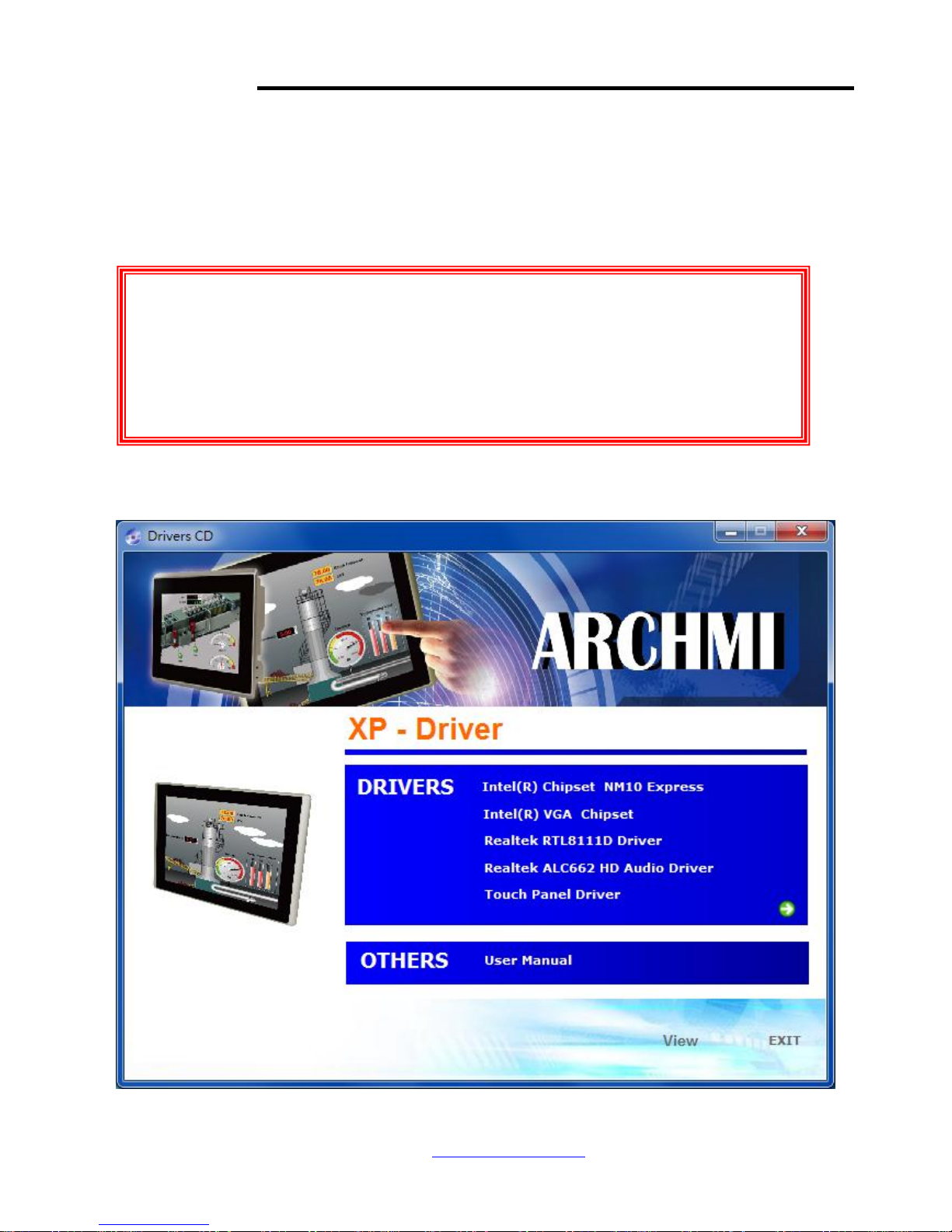
Chapter 4 Installation of Drivers
This chapter describes the installation procedures for software and drivers under the windows XP.
The software and drivers are included with the motherboard. The contents include Intel chipset driver,
VGA driver, LAN drivers, Audio driver Installation instructions are given below.
I
Important Note:
After installing your Windows operating system (Windows XP), you must install
first the Intel Chipset Software Installation Utility before proceeding with the
installation of drivers.
Page 54
NVHMI SERIES User Manual www.nemavision-ipc.com
54
4.1 Intel Chipset Driver
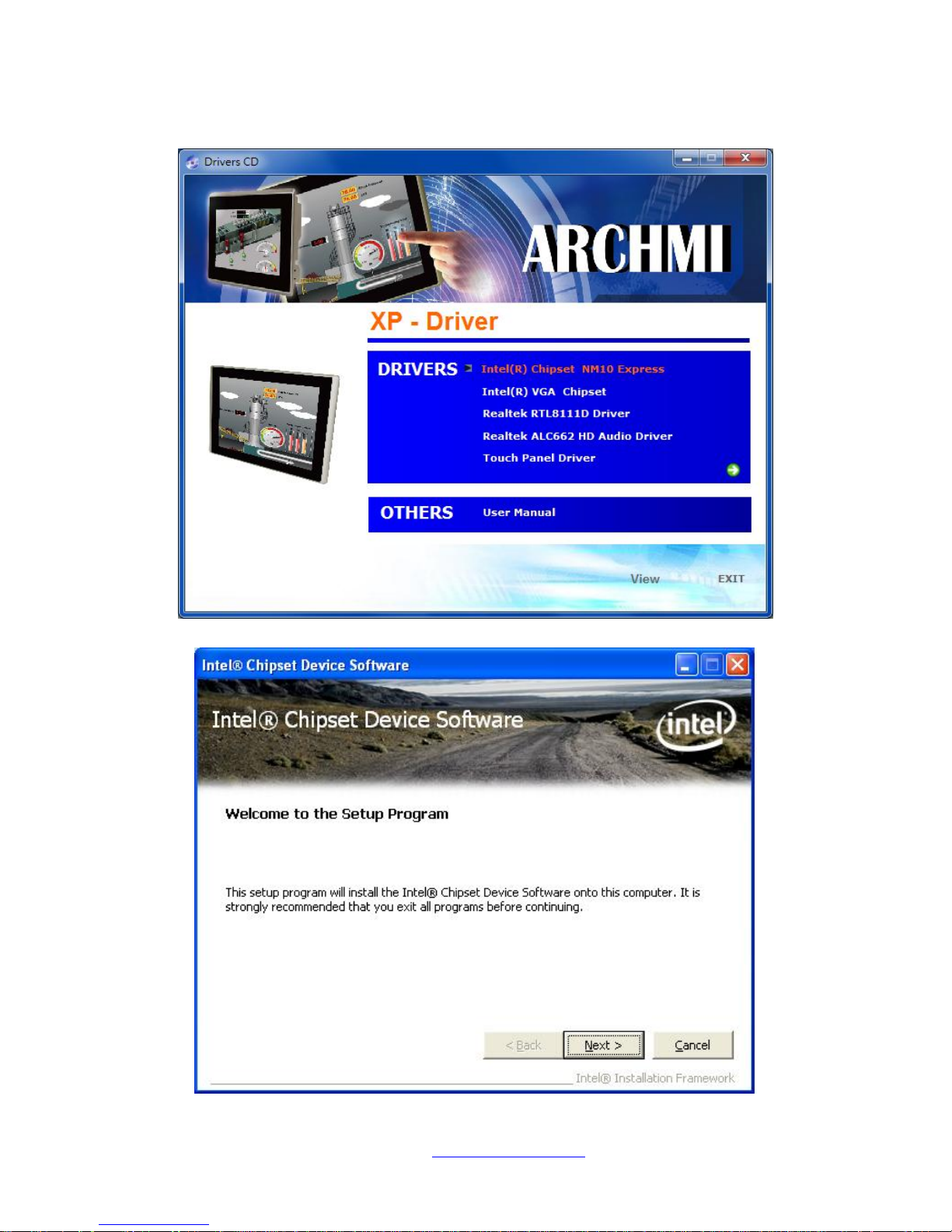
To install the Intel chipset driver, please follow the steps below.
Step 1. Select Intel (R) Chipset NM10 Express from the list
Step 2. Click Next to setup program.
Page 55
NVHMI SERIES User Manual www.nemavision-ipc.com
55
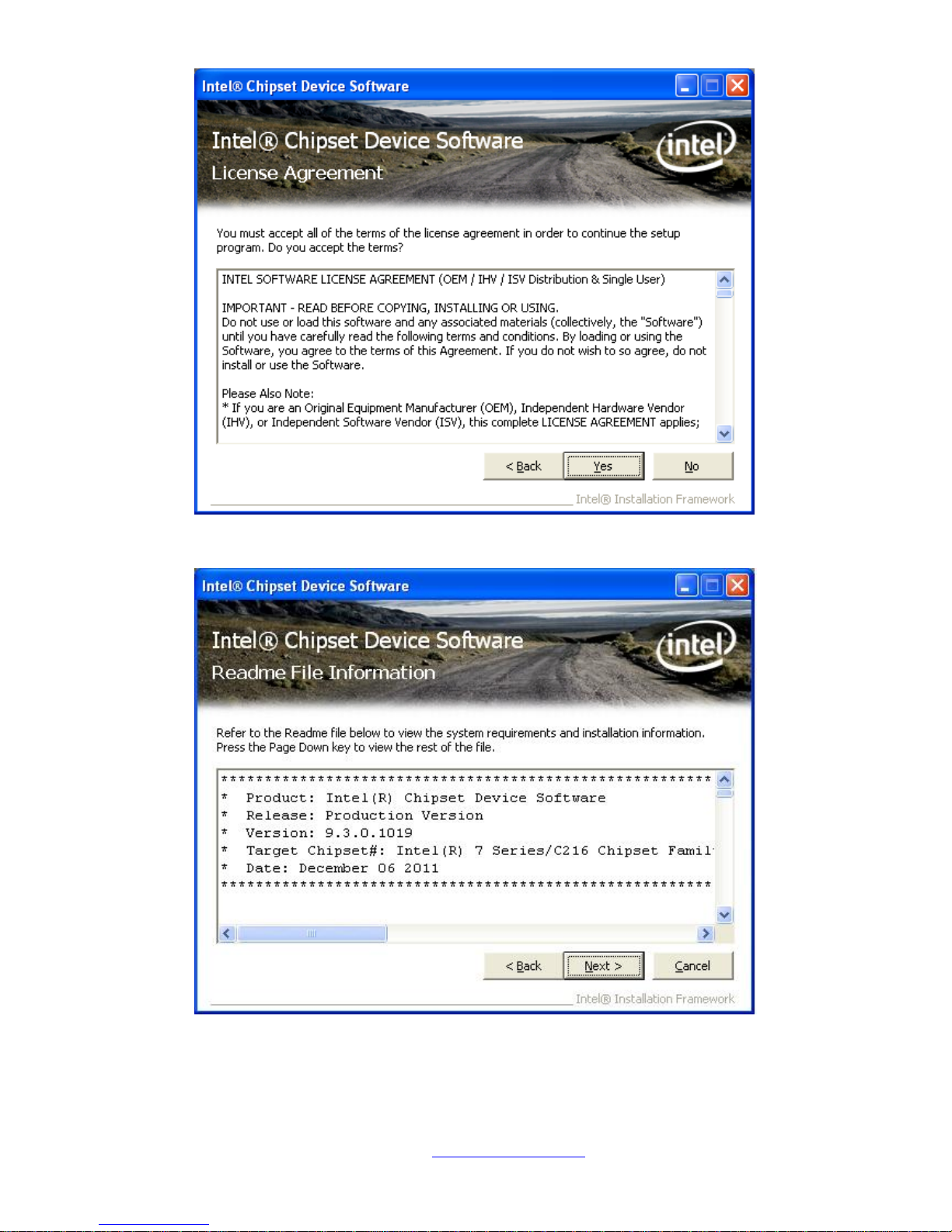
Step 3. Read the license agreement. Click Yes to accept all of the terms of the license agreement.
Step 4. Click Next to continue.
Page 56
NVHMI SERIES User Manual www.nemavision-ipc.com
56
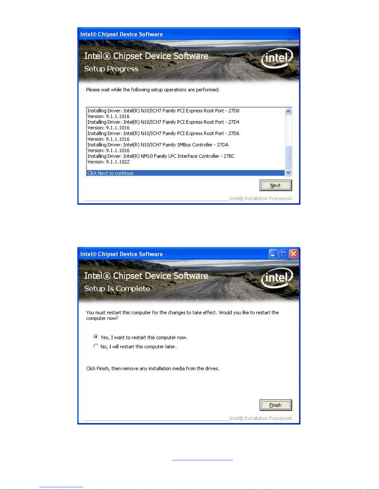
Step 5. Click Next.
Step 6. Select Yes, I want to restart this computer now. Click Finish, then remove any installation
media from the drives.
Page 57
NVHMI SERIES User Manual www.nemavision-ipc.com
57
4.2 Intel Graphics Media Accelerator driver
To install the VGA drivers, follow the steps below to proceed with the installation.
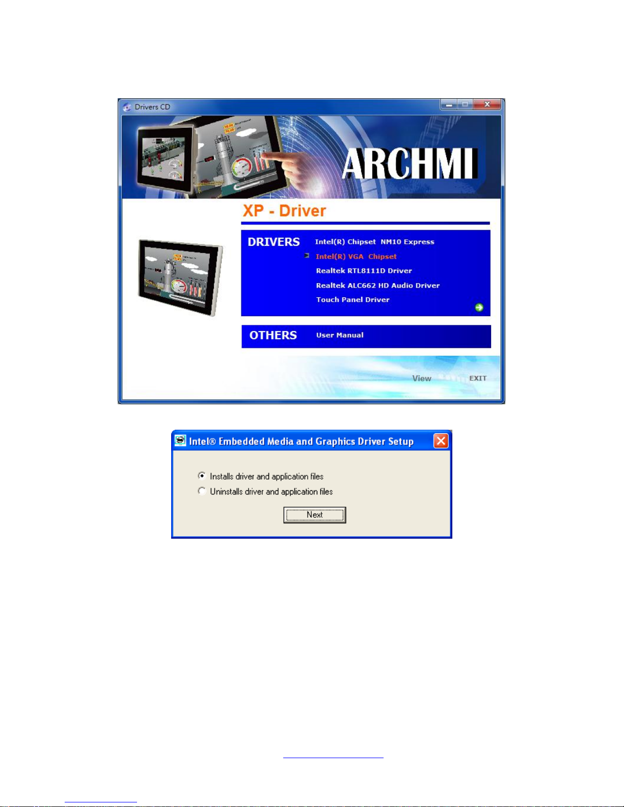
Step 1.Select Intel(R) VGA Chipset Driver.
Step 2. Select Installs driver and application files. Click Next.
Page 58
NVHMI SERIES User Manual www.nemavision-ipc.com
58
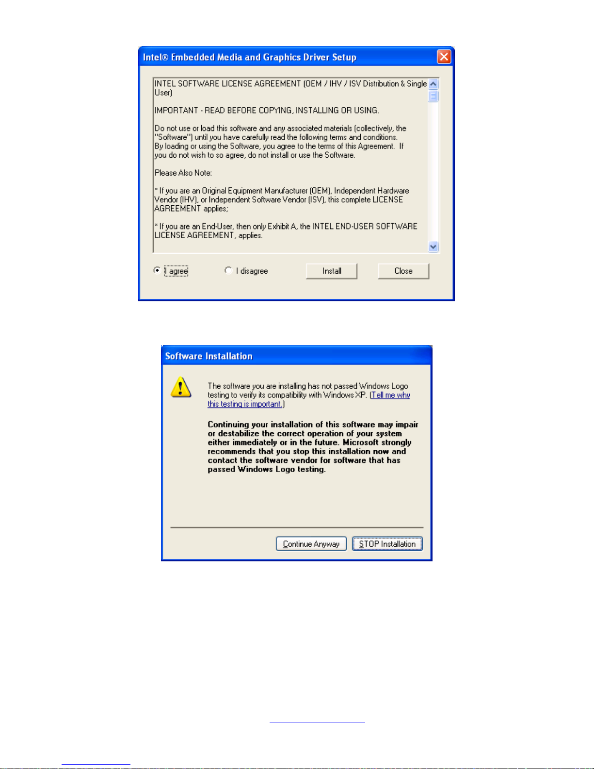
Step 3. Select I agree. Click Install.
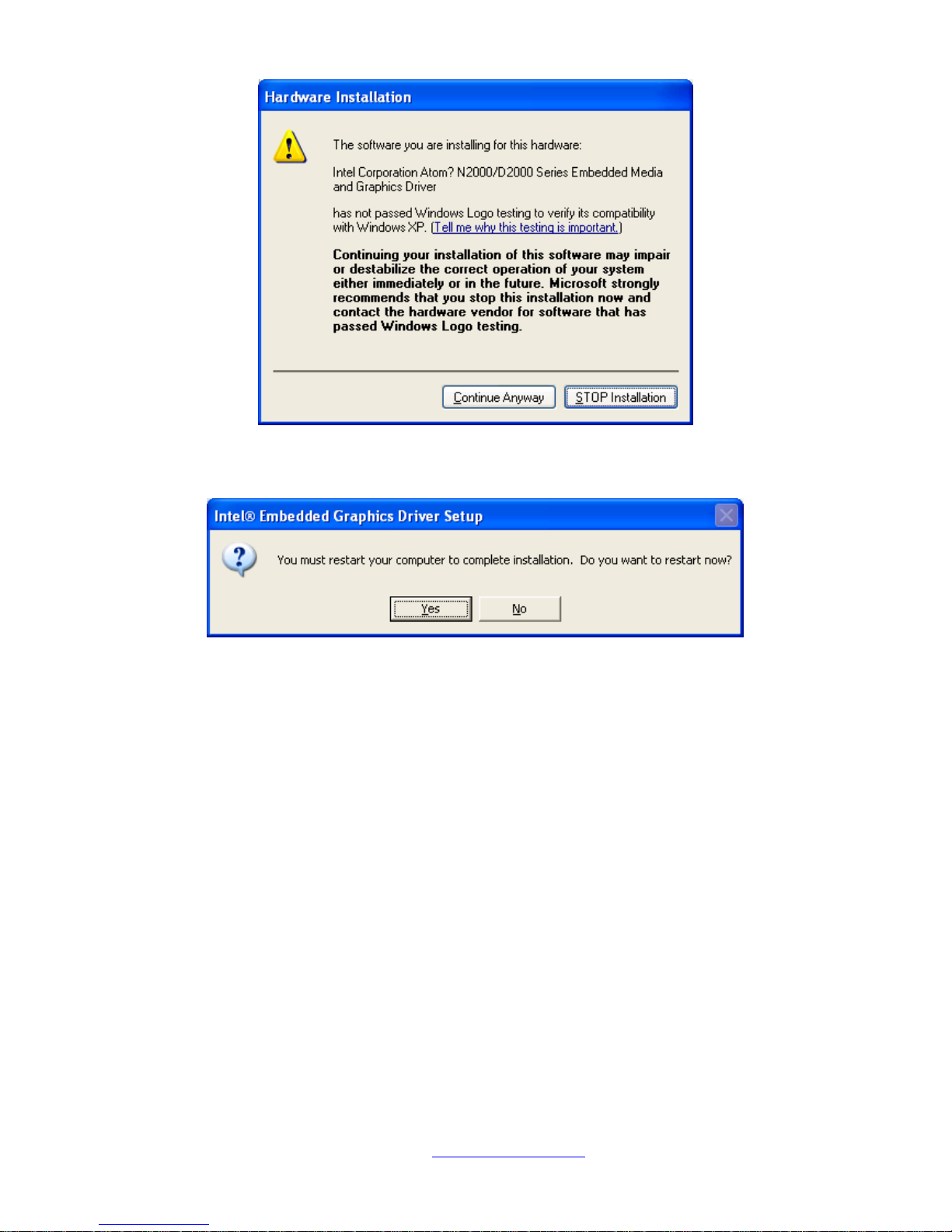
Step 4. Click Continue Anyway.
Page 59
NVHMI SERIES User Manual www.nemavision-ipc.com
59
Step 5. Click Continue Anyway.
Step 6. To restart the computer, click Yes.
Page 60
NVHMI SERIES User Manual www.nemavision-ipc.com
60
4.3 Intel (R) Network Adapter
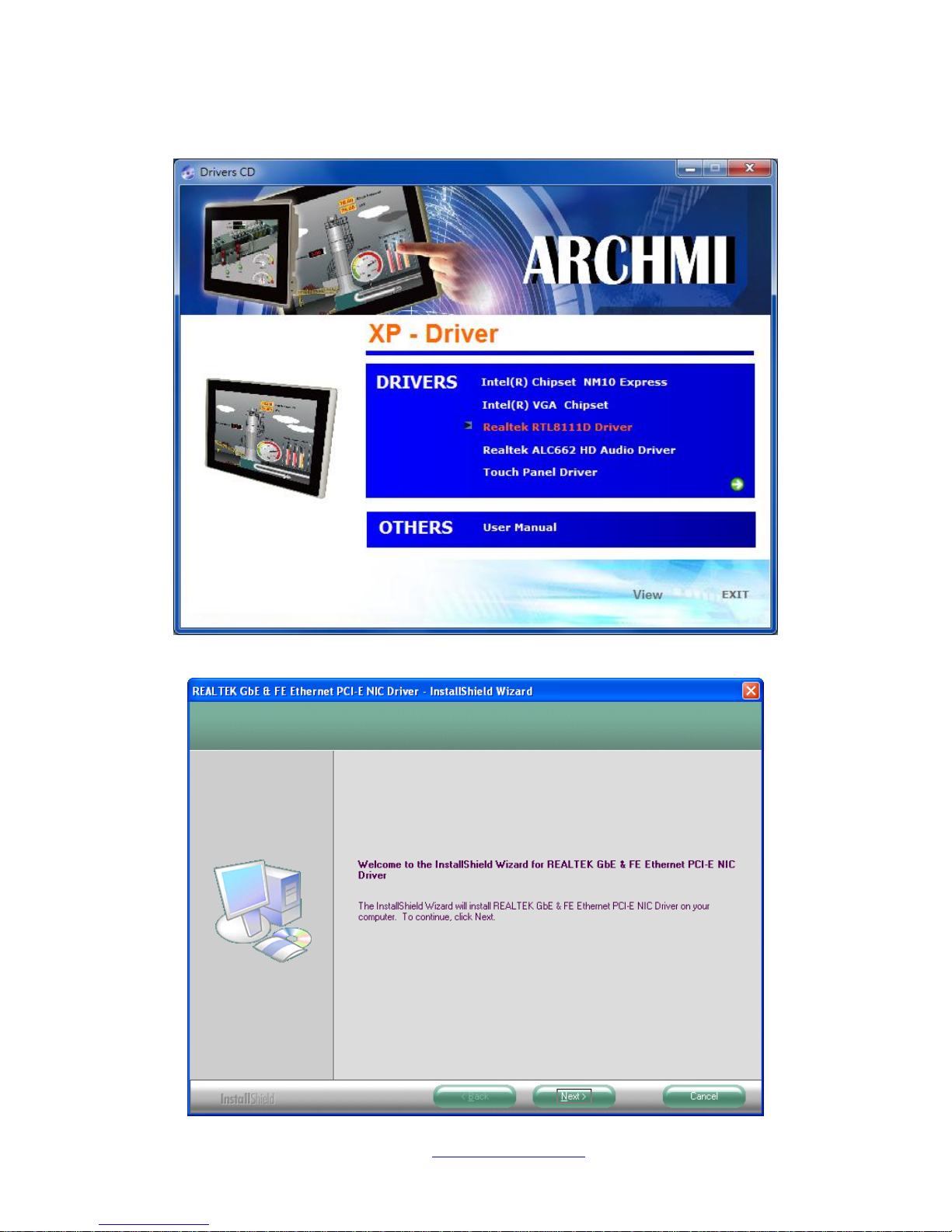
To install the Intel (R) Network Adapter device driver, please follow the steps below.
Step 1. Select Realtek RTL8111D Driver.
Step 2. Click Next to continue.
Page 61
NVHMI SERIES User Manual www.nemavision-ipc.com
61
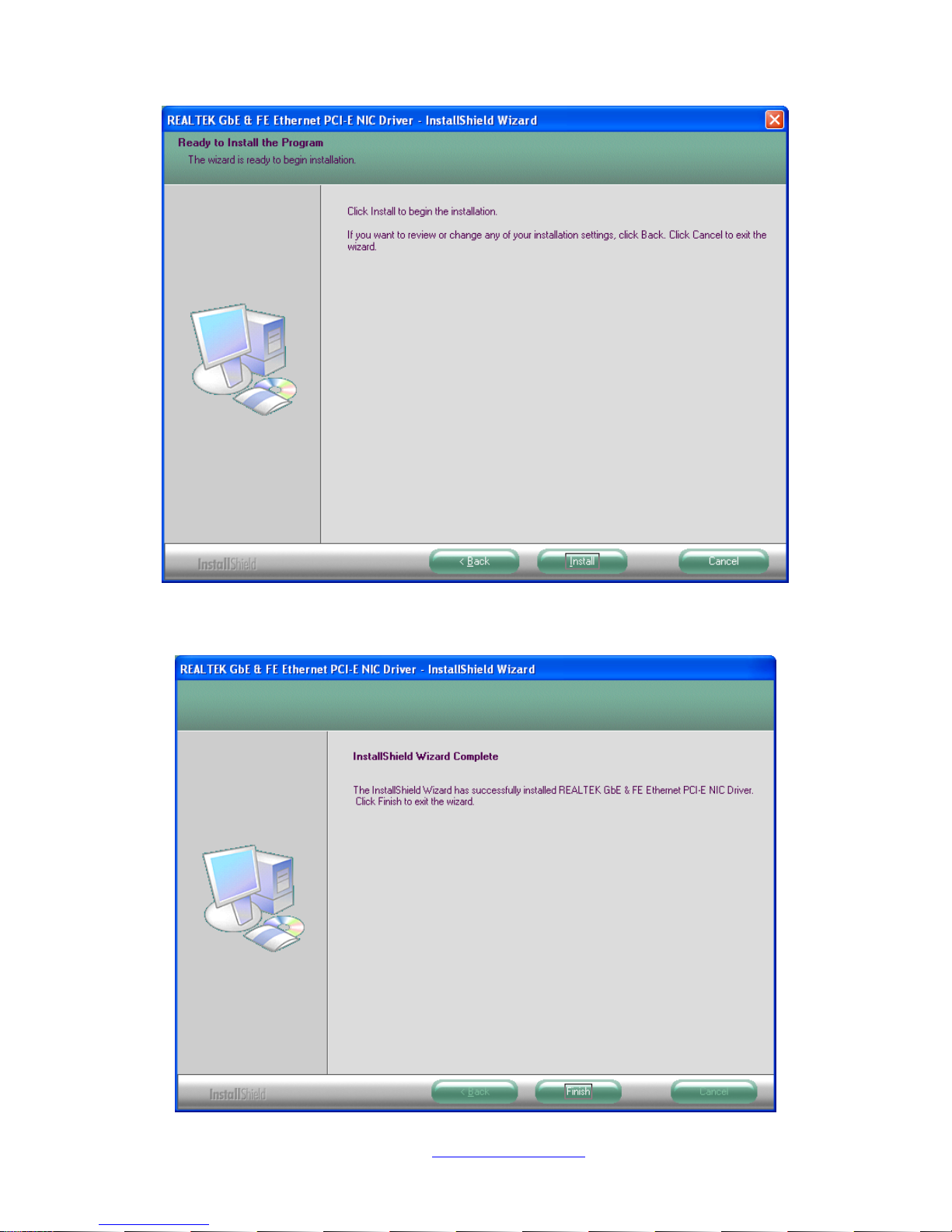
Step 3. Click Install to begin the installation.
Step 4. Click Finish to exist the wizard.
Page 62
NVHMI SERIES User Manual www.nemavision-ipc.com
62
4.4 Realtek ALC662 HD Audio Codec Driver Installation
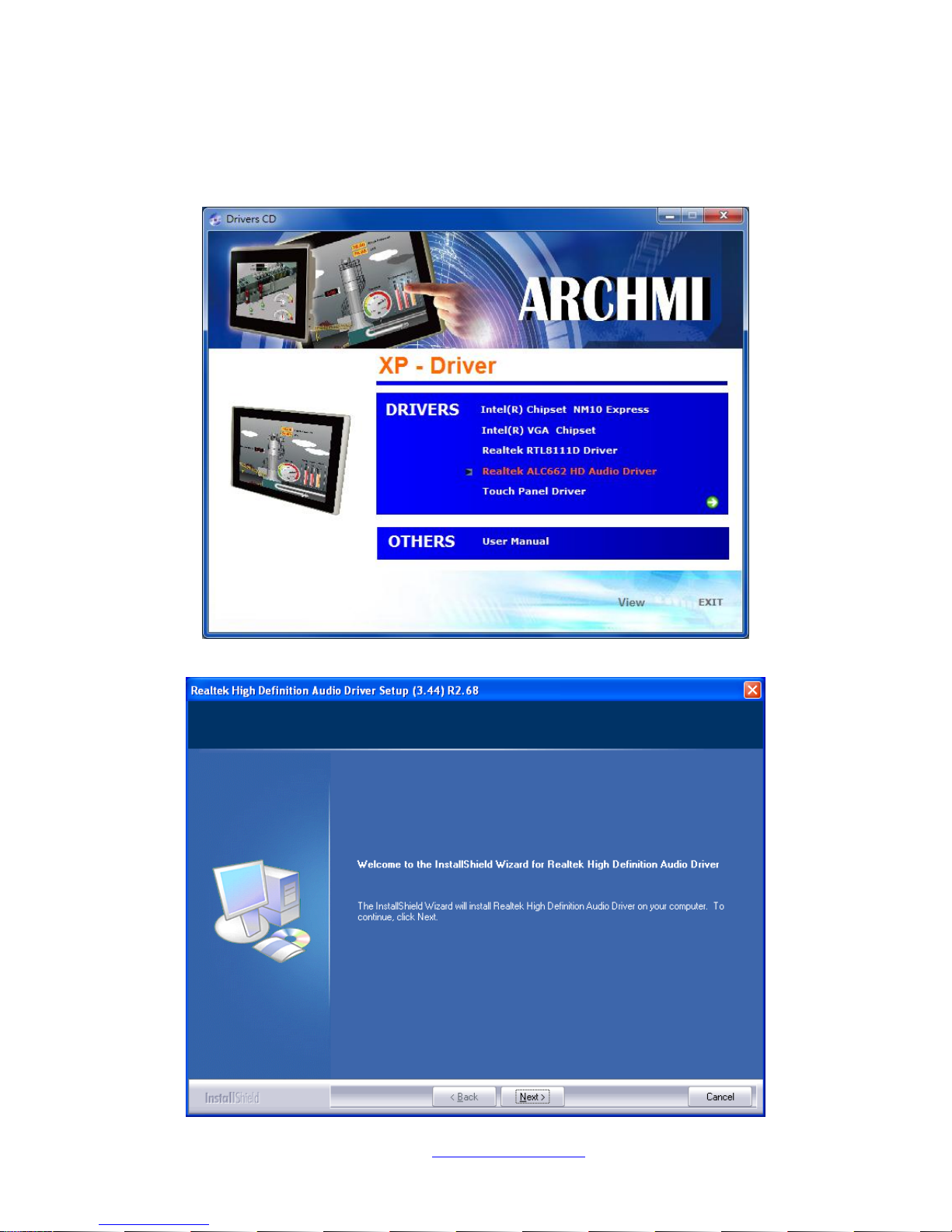
To install the Realtek ALC662 HD Audio Codec Driver, please follow the steps below.
Step 1. Select Realtek AL662 Audio Codec Driver from the list
Step 2. Click Next to continue.
Page 63
NVHMI SERIES User Manual www.nemavision-ipc.com
63
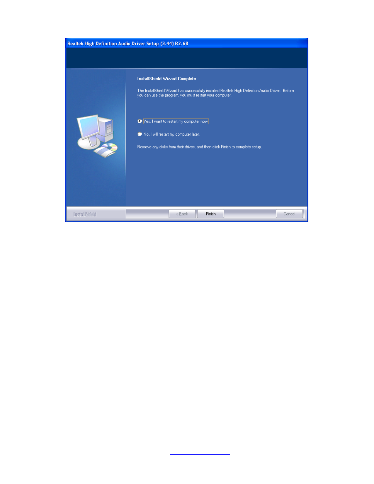
Step 3. Click Yes, I want to restart my computer now. Click Finish to complete the installation.
Page 64
NVHMI SERIES User Manual www.nemavision-ipc.com
64
Chapter 5 Touch Screen Installation
This chapter describes how to install drivers and other software that will allow your touch screen work
with different operating systems.
5.1 Windows 2000/XP/2003/Vista/WIN7 Universal Driver
Installation for PenMount 6000 Series
Before installing the Windows 2000/XP driver software, you must have the Windows 2000/XP system
installed and running on your computer. You must also have one of the following PenMount 6000
series controller or control boards installed: PM6500, PM6300.
5.1.1 Installing Software(Resistive Touch)
If you have an older version of the PenMount Windows 2000/XP driver installed in your system, please
remove it first. Follow the steps below to install the PenMount DMC6000 Windows 2000/XP driver.
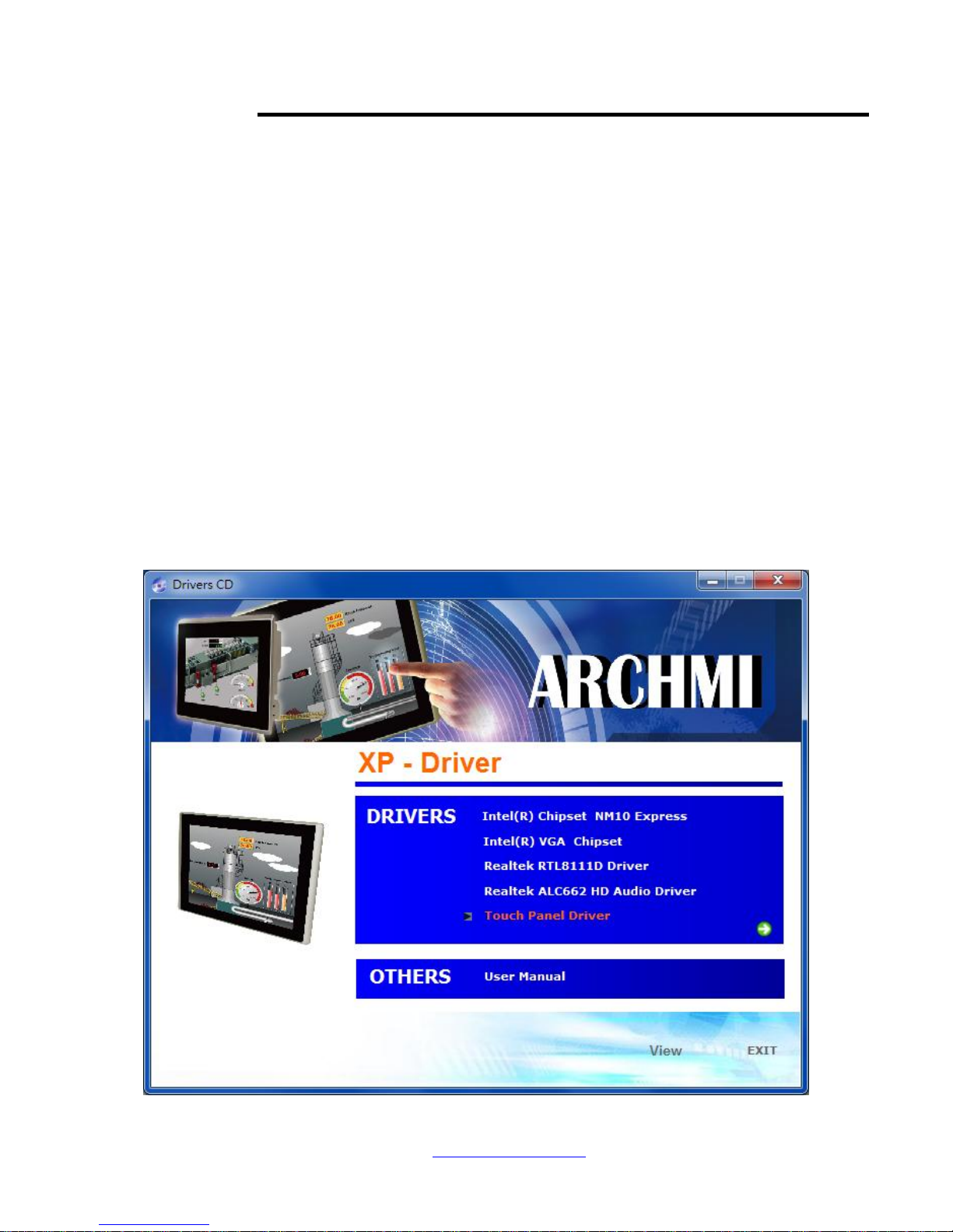
Step 1. Insert the product CD, the screen below would appear. Click touch panel driver.
Page 65
NVHMI SERIES User Manual www.nemavision-ipc.com
65
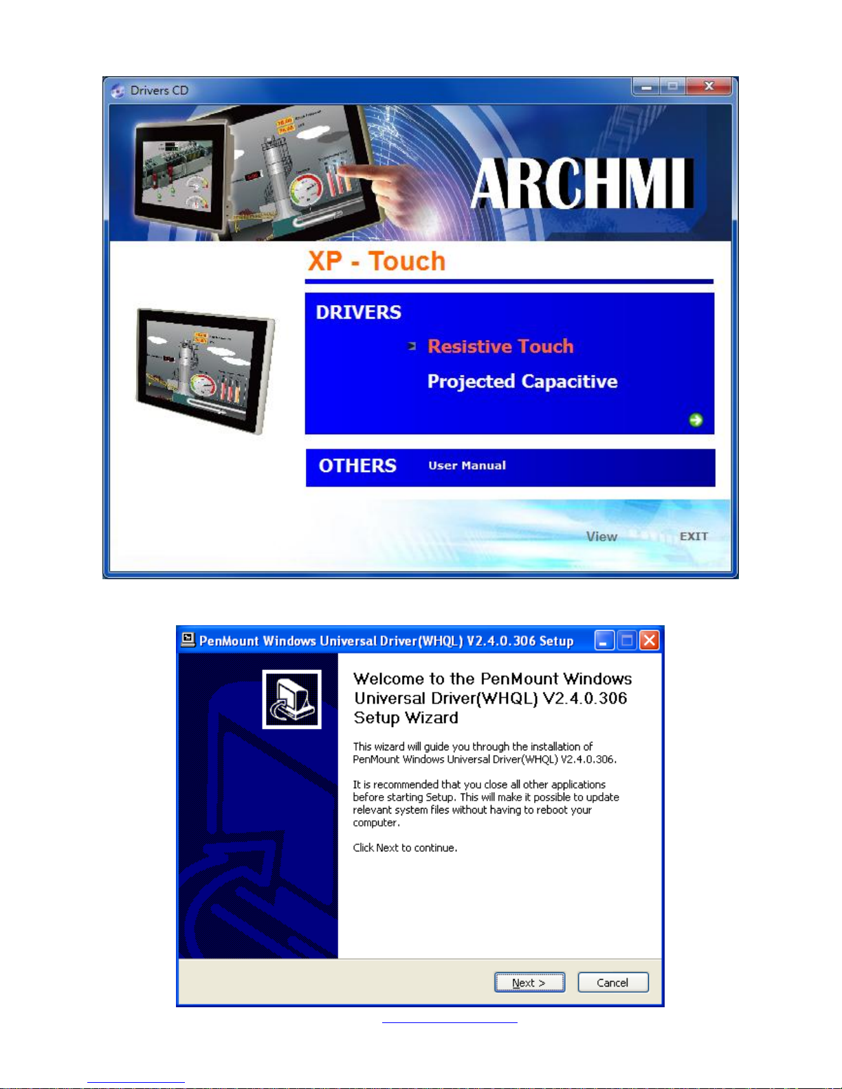
Step 2. Select Resistive Touch.
Step 3. Click Next to continue.
Page 66
NVHMI SERIES User Manual www.nemavision-ipc.com
66
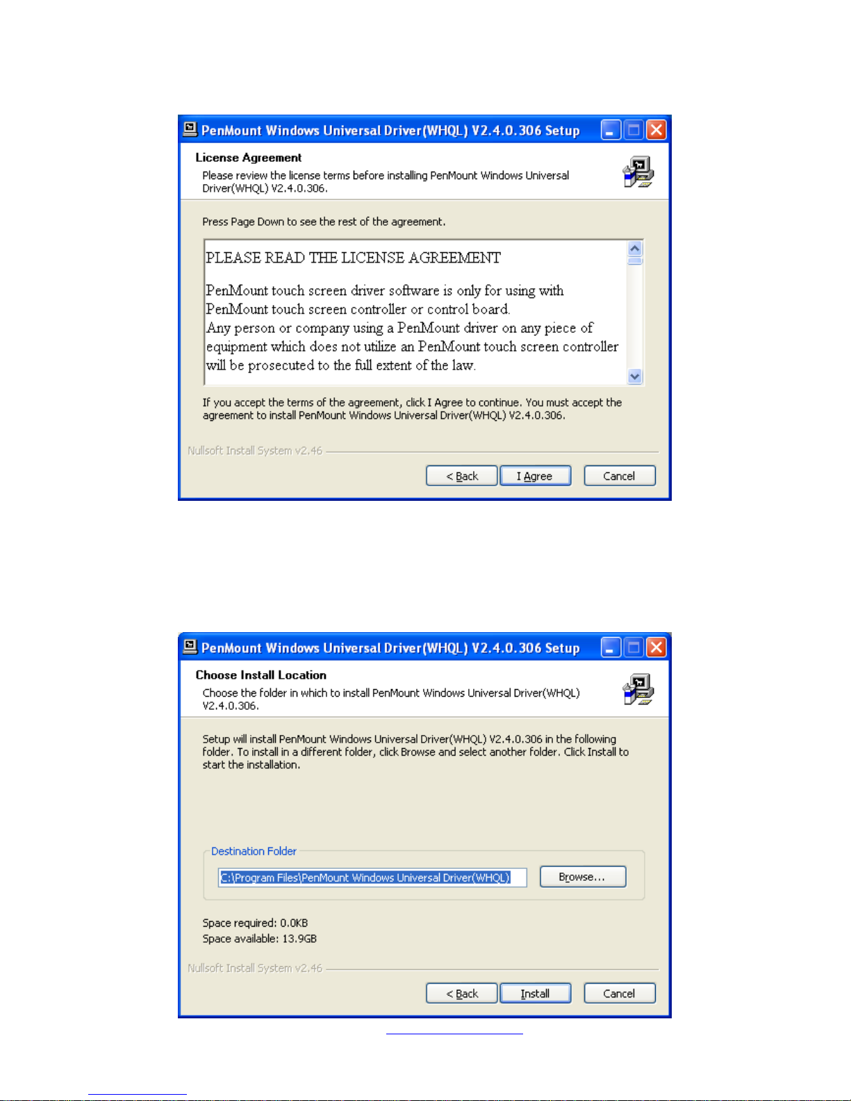
Step 4. Read the license agreement. Click I Agree to agree the license agreement.
Step 5. Choose the folder in which to install PenMount Windows Universal Driver. Click Install to
start the installation.
Page 67
NVHMI SERIES User Manual www.nemavision-ipc.com
67
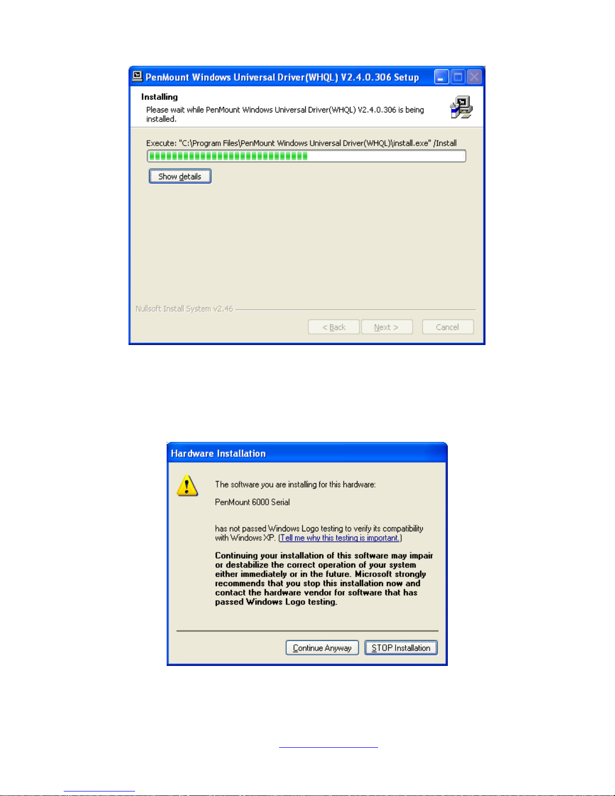
Step 6. Wait for installation. Then click Next to continue.
Step 7. Click Continue Anyway.
Page 68
NVHMI SERIES User Manual www.nemavision-ipc.com
68
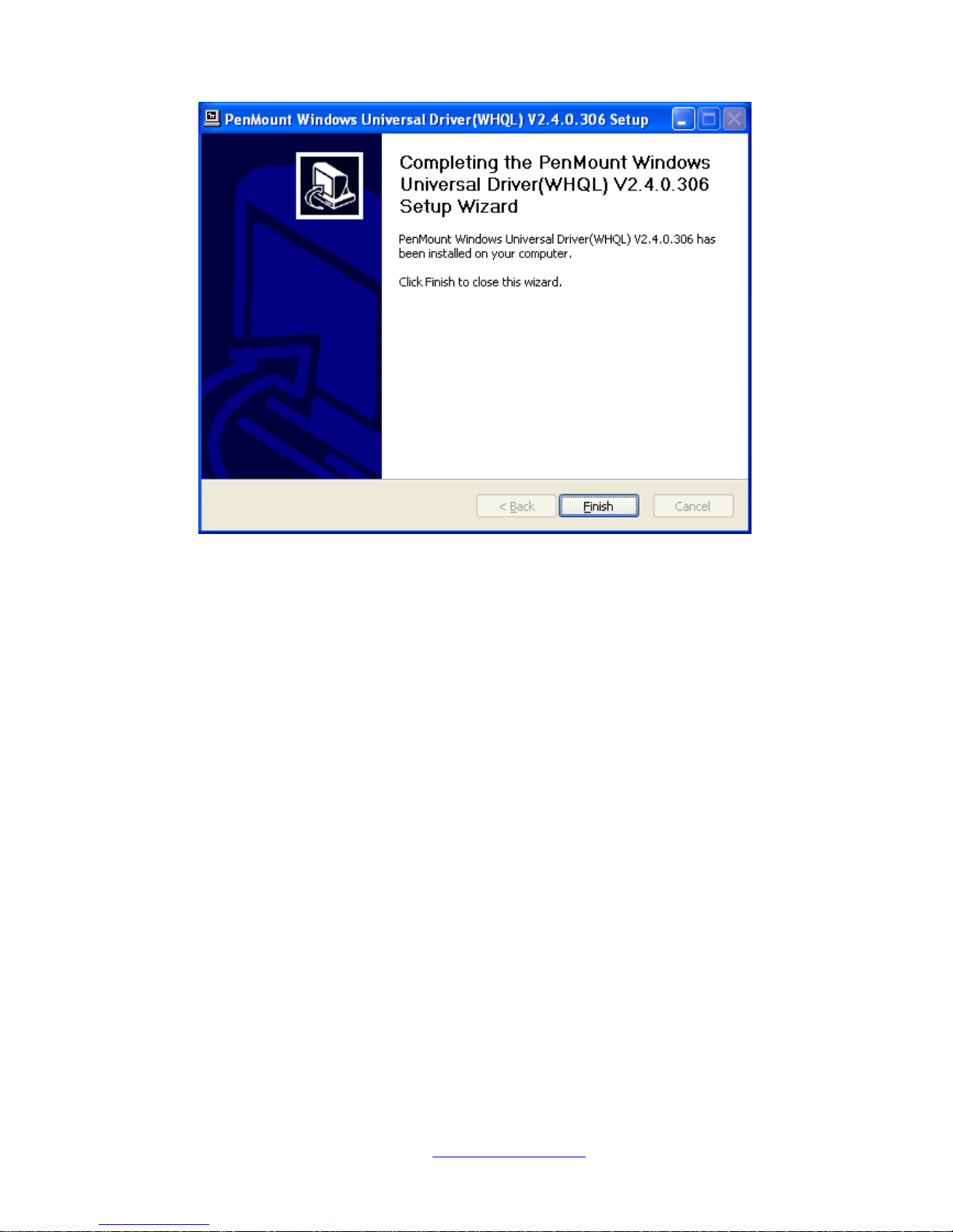
Step 8. Click Finish to complete installation.
Page 69
NVHMI SERIES User Manual www.nemavision-ipc.com
69
5.1.2 Installing Software (Projected Capacitive)
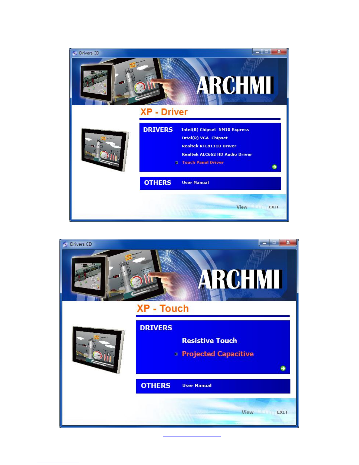
Step 1. Insert the product CD, the screen below would appear. Click touch panel driver.
Step 2. Select Projected Capacitive.
Page 70
NVHMI SERIES User Manual www.nemavision-ipc.com
70
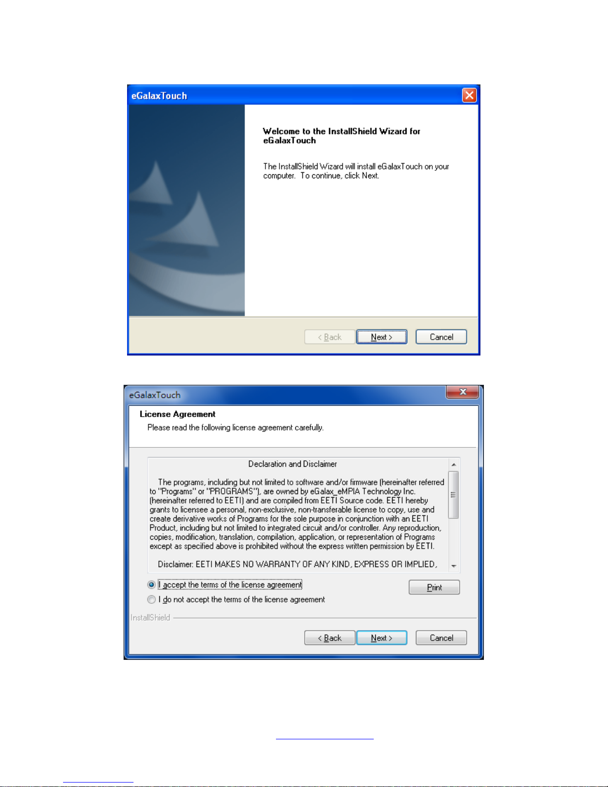
Step 3. Click Next to continue.
Step 4. Select I accept the terms of the license agreement. Click Next.
Page 71
NVHMI SERIES User Manual www.nemavision-ipc.com
71
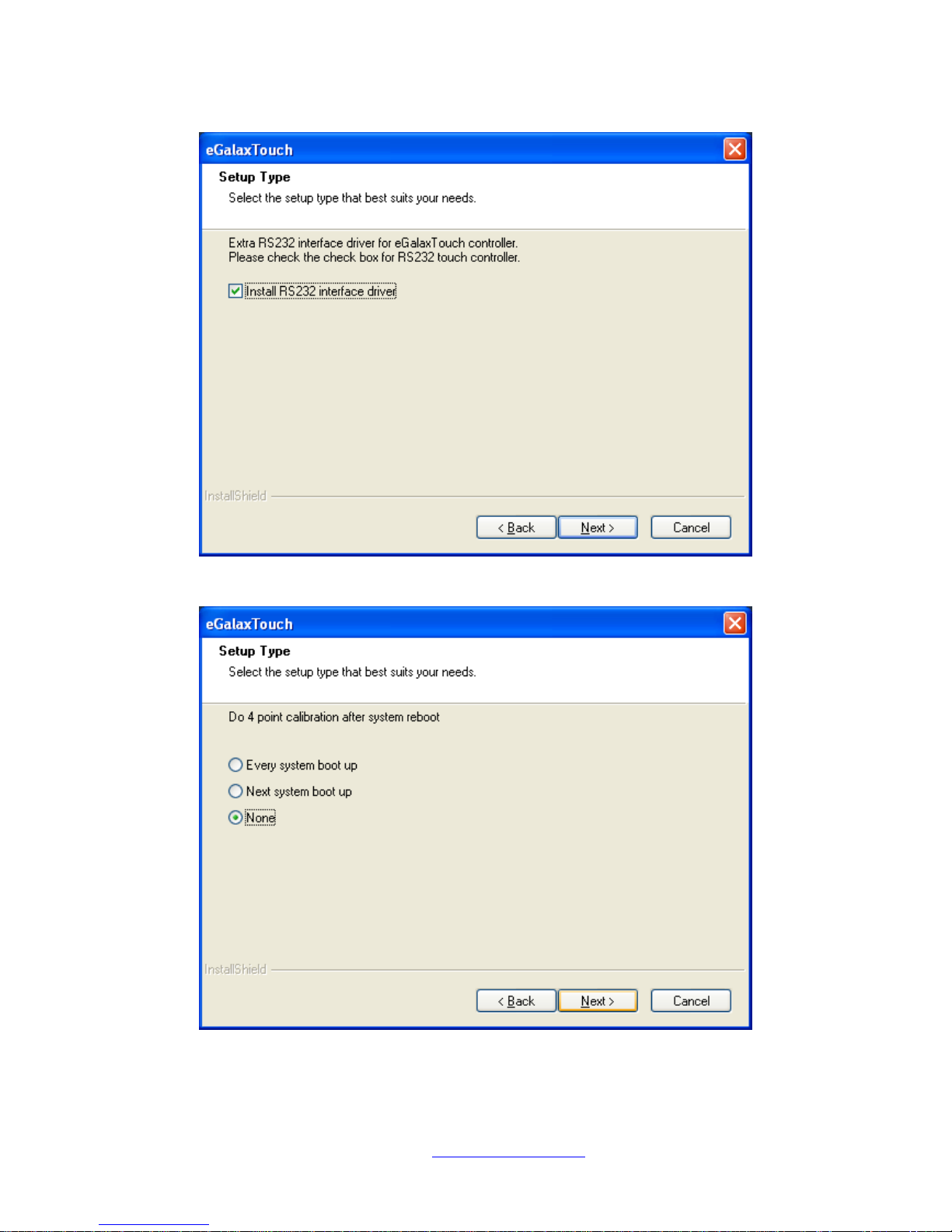
Step 5. Tick Install RS232 interface driver. Click Next.
Step 6. Select None. Click Next.
Page 72
NVHMI SERIES User Manual www.nemavision-ipc.com
72
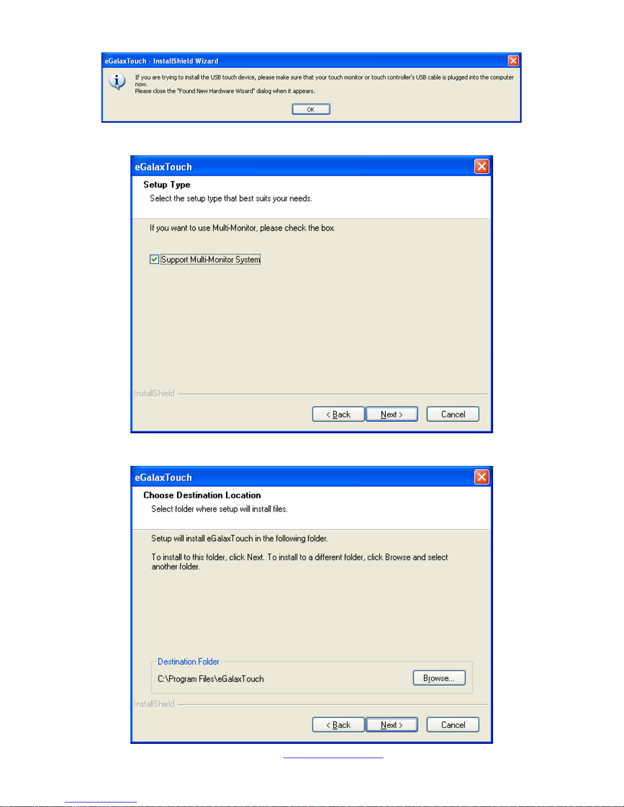
Step 7. Click OK.
Step 8. Tick Support Muti-Monitor System. Click Next.
Step 9. Go to C:\Program Files\eGalaxTouch. Click Next.
Page 73
NVHMI SERIES User Manual www.nemavision-ipc.com
73
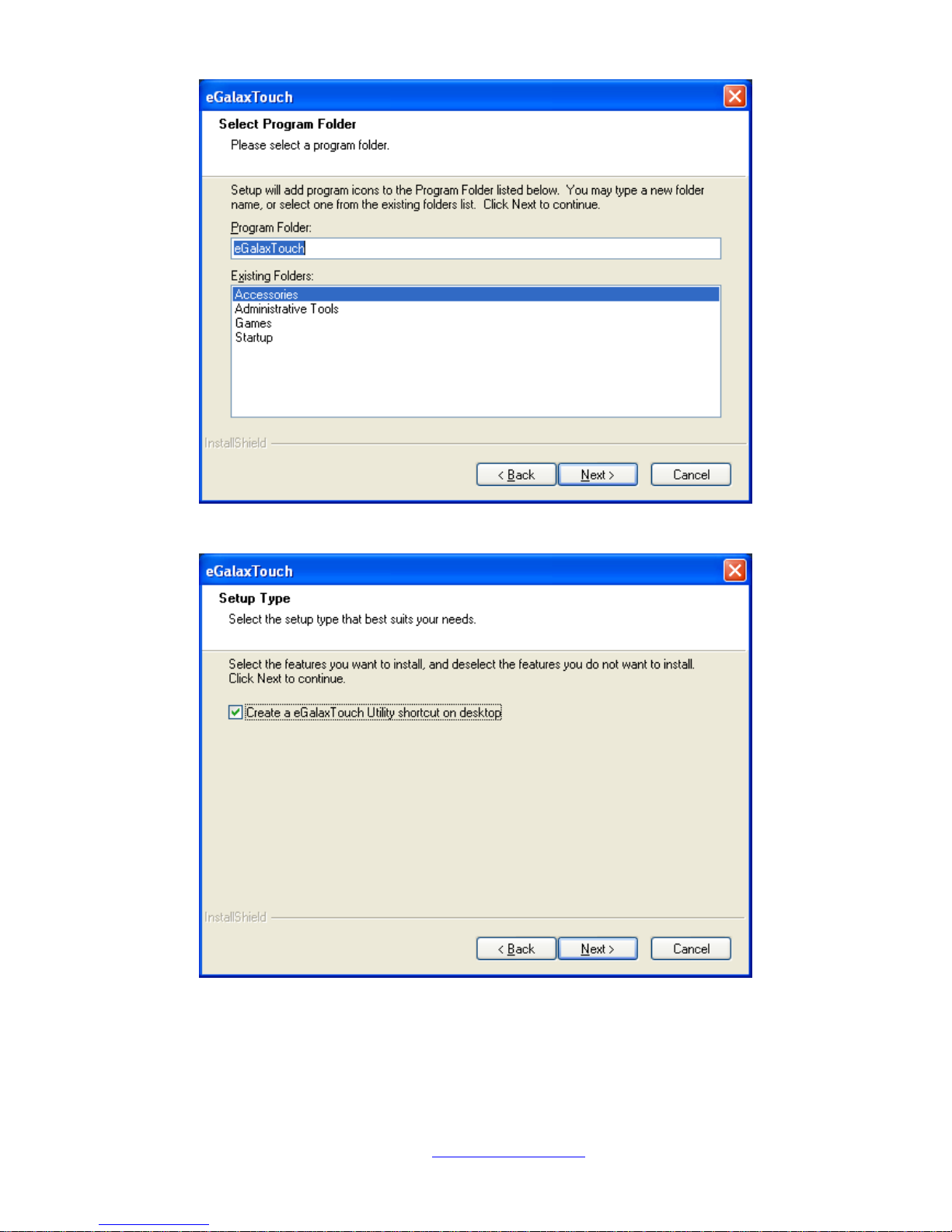
Step 10. Click Next.
Step 11. Tick Create a eGalaxTouch Utility shortcut on desktop. Click Next.
Page 74
NVHMI SERIES User Manual www.nemavision-ipc.com
74
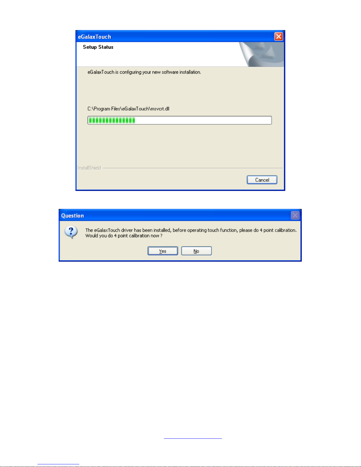
Step 12. Wait for installation.
Step 13. Click Yes to do 4 point calibration.
5.2.1 Software Functions(Resistive Touch)
Upon rebooting, the computer automatically finds the new 6000 controller board. The touch screen is
connected but not calibrated. Follow the procedures below to carry out calibration.
1. After installation, click the PenMount Monitor icon “PM” in the menu bar.
2. When the PenMount Control Panel appears, select a device to “Calibrate.”
PenMount Control Panel(Resistive Touch)
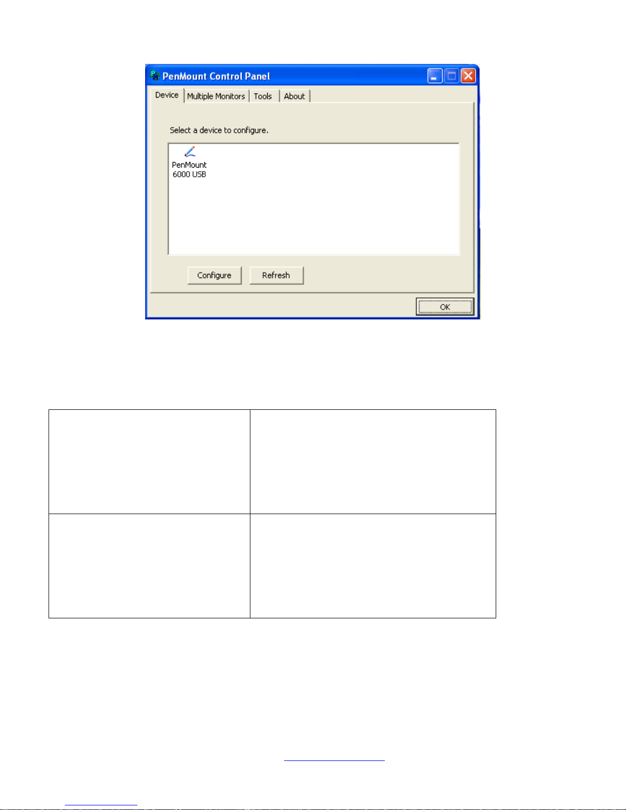
The functions of the PenMount Control Panel are Device, Multiple Monitors ,Tools and About,
which are explained in the following sections.
Page 75
NVHMI SERIES User Manual www.nemavision-ipc.com
75
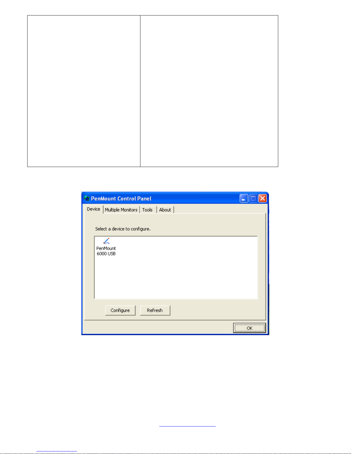
Device
In this window, you can find out that how many devices be detected on your system.
Calibrate
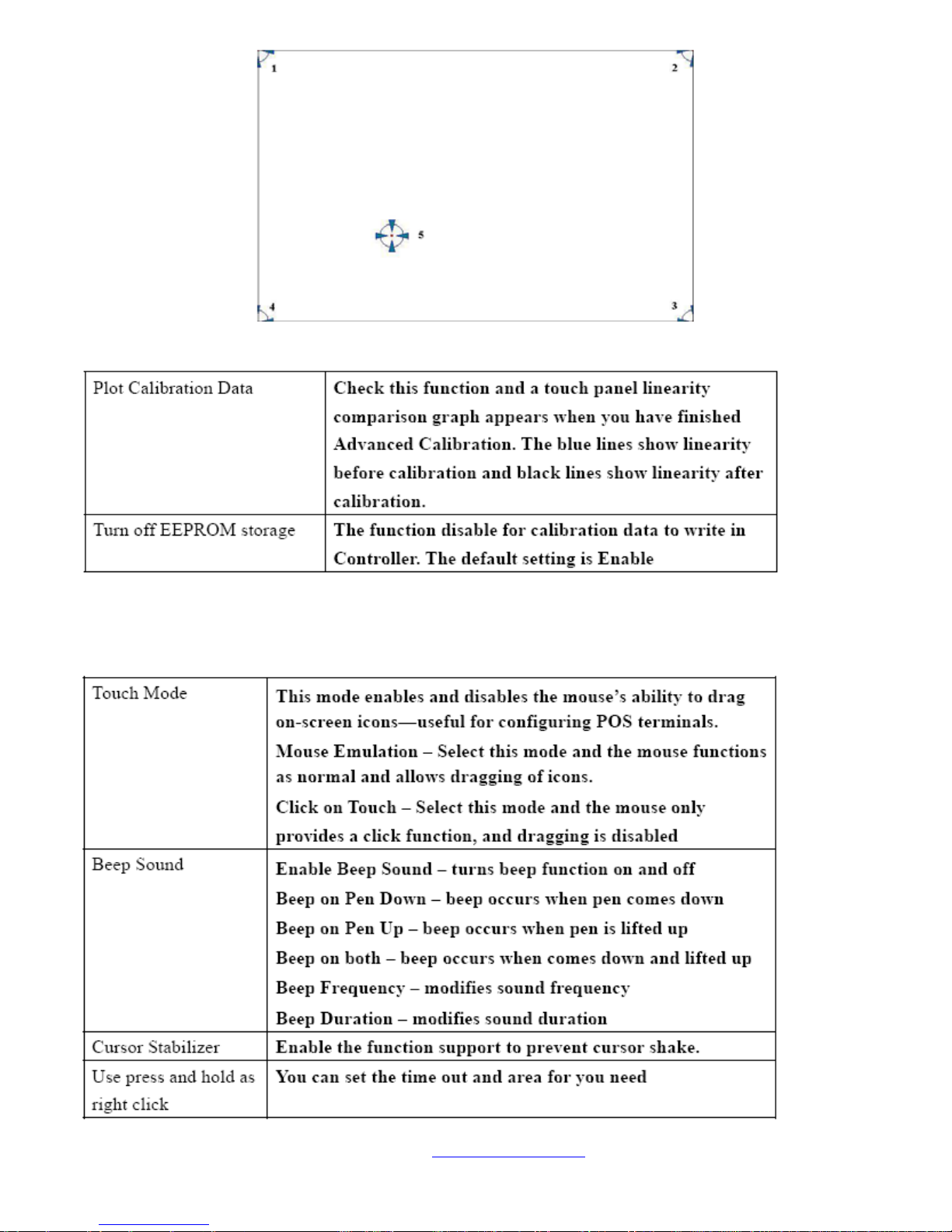
This function offers two ways to calibrate your touch screen. ‘Standard Calibration’ adjusts most touch
screens. ‘Advanced Calibration’ adjusts aging touch screens.
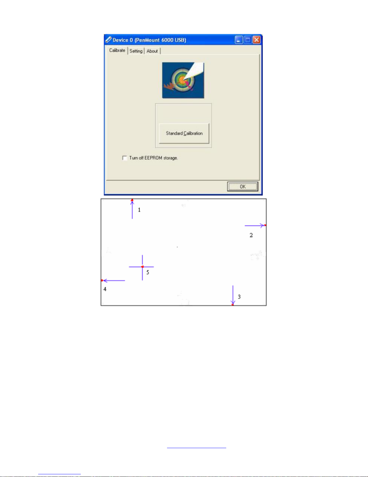
Standard Calibration
Click this button and arrows appear
pointing to red squares. Use your finger or
stylus to touch the red squares in
sequence. After the fifth red point
calibration is complete. To skip, press
‘ESC’.
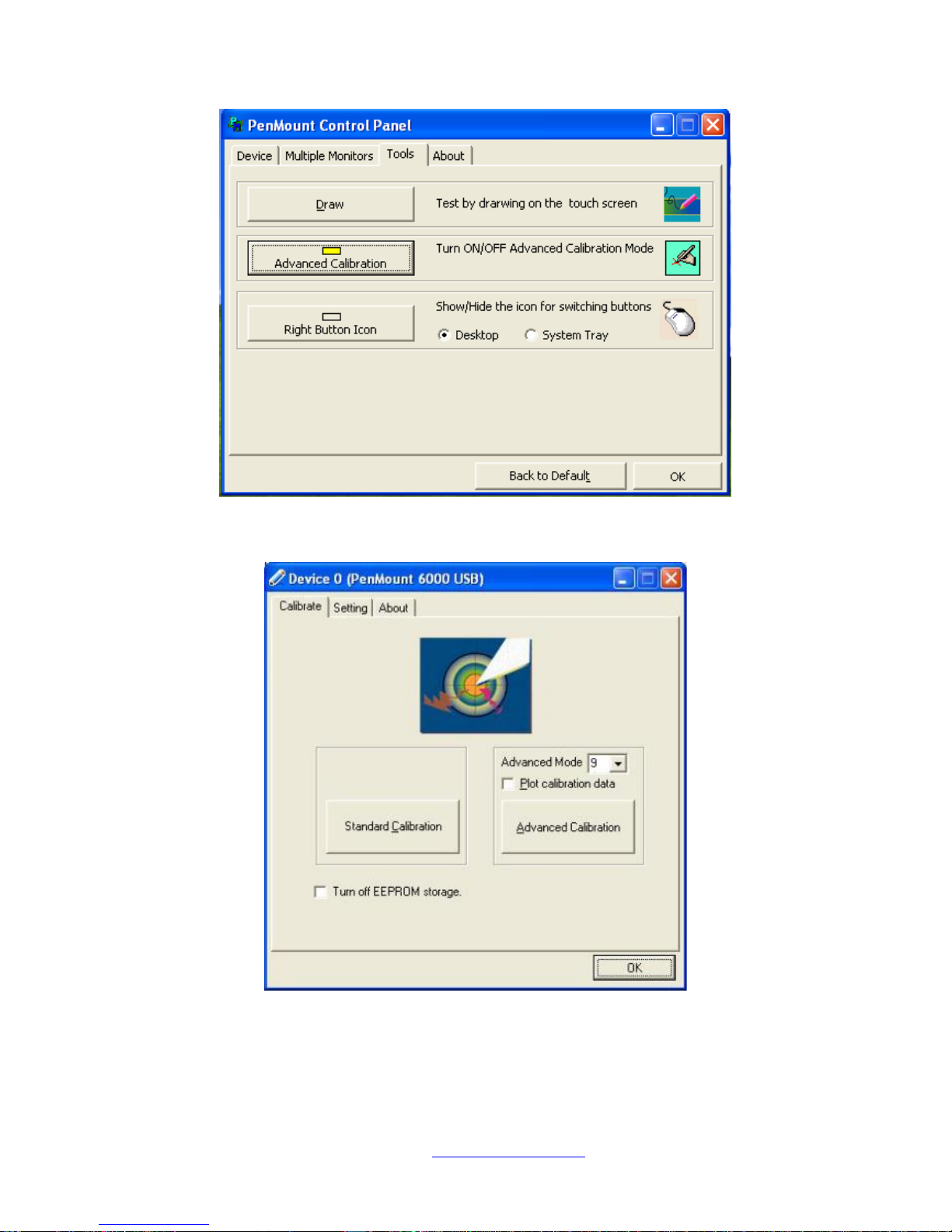
Advanced Calibration
Advanced Calibration uses 4, 9, 16 or 25
points to effectively calibrate touch panel
linearity of aged touch screens. Click this
button and touch the red squares in
sequence with a stylus. To skip, press
ESC’.
Page 76
NVHMI SERIES User Manual www.nemavision-ipc.com
76
Command Calibration
Command call calibration function. Use
command mode call calibration function,
this can uses Standard, 4, 9, 16 or 25
points to calibrate E.g. Please run ms-dos
prompt or command prompt c:\Program
Files\PenMount Universa Driver\Dmcctrl.exe
-calibration 0 ( Standard Calibration)
Dmcctrl.exe - calibration ($) 0= Standard
Calibration 4=Advanced Calibration 4
9=Advanced Calibration 9 16=Advanced
Calibration 16 25=Advanced Calibration 25
Step 1. Please select a device then click “Configure”. You can also double click the device too.
Page 77
NVHMI SERIES User Manual www.nemavision-ipc.com
77
Step 2.Click “Standard Calibration” to start calibration procedure
NOTE: The older the touch screen, the more Advanced Mode calibration points you need for an
accurate calibration. Use a stylus during Advanced Calibration for greater accuracy. Please follow the
step as below:
Page 78
NVHMI SERIES User Manual www.nemavision-ipc.com
78
Step 3.Come back to “PenMount Control Panel” and select Tools then click Advanced
Calibration.
Step 4. Select Device to calibrate, then you can start to do Advanced Calibration.
NOTE: Recommend to use a stylus during Advanced Calibration for greater accuracy.
Page 79
NVHMI SERIES User Manual www.nemavision-ipc.com
79
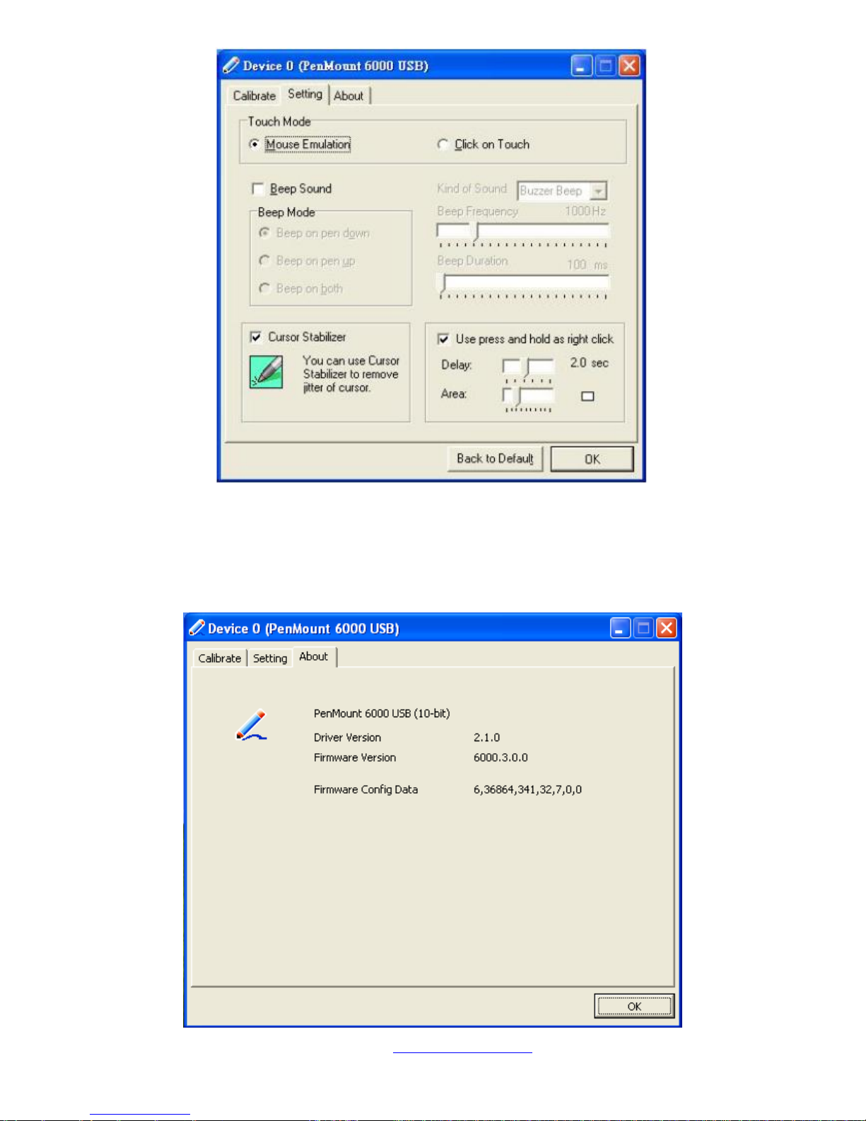
Setting
Page 80
NVHMI SERIES User Manual www.nemavision-ipc.com
80
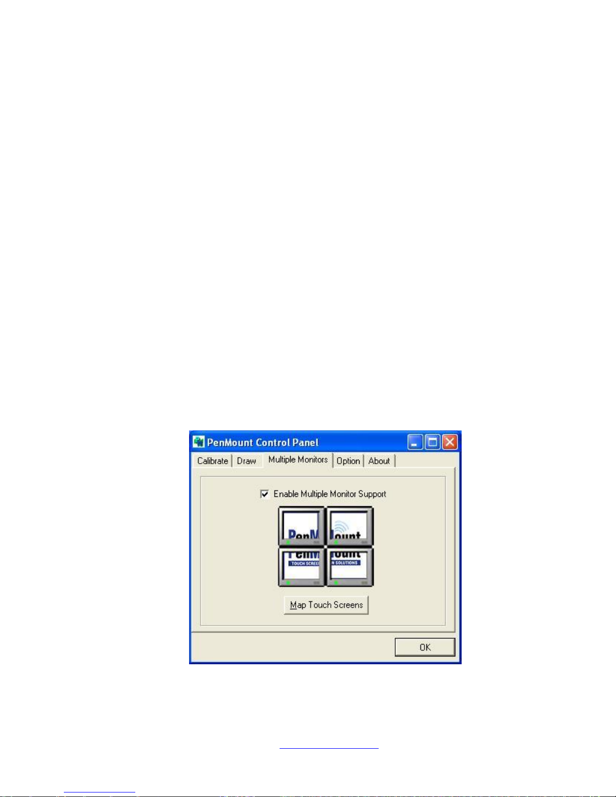
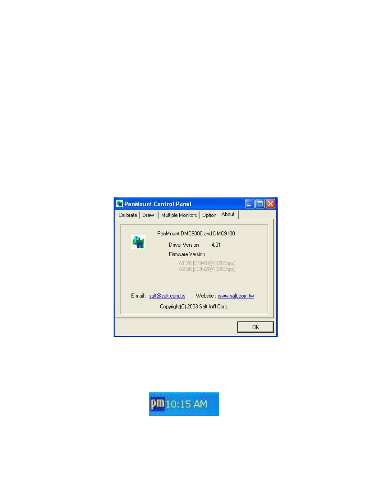
About
This panel displays information about the PenMount controller and driver version.
Page 81
NVHMI SERIES User Manual www.nemavision-ipc.com
81
Multiple Monitors
Multiple Monitors support from two to six touch screen displays for one system.
The PenMount drivers for Windows 2000/XP support Multiple Monitors. This function supports
from two to six touch screen displays for one system. Each monitor requires its own PenMount
touch screen control board, either installed inside the display or in a central unit. The PenMount
control boards must be connected to the computer COM ports via the RS-232 interface. Driver
installation procedures are the same as for a single monitor. Multiple Monitors support the
following modes:
Windows Extends Monitor Function
Matrox DualHead Multi-Screen Function
nVidia nView Function
NOTE: The Multiple Monitor function is for use with multiple displays only. Do not use this
function if you have only one touch screen display. Please note once you turn on this
function the rotating function is disabled.
Enable the multiple display function as follows:
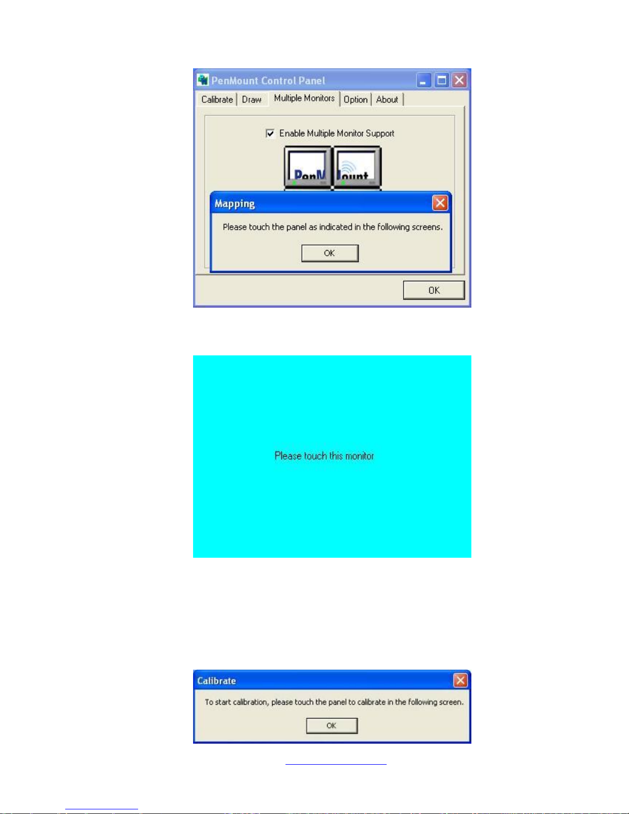
1. Check the Enable Multiple Monitor Support box; then click Map Touch Screens to
assign touch controllers to displays.
Page 82
NVHMI SERIES User Manual www.nemavision-ipc.com
82
2. When the mapping screen message appears, click OK.
3. Touch each screen as it displays “Please touch this monitor”. Following this
sequence and touching each screen is called mapping the touch screens.
4. Touching all screens completes the mapping and the desktop reappears on the
monitors.
5. Select a display and execute the “Calibration” function. A message to start calibration
appears. Click OK.
Page 83
NVHMI SERIES User Manual www.nemavision-ipc.com
83
6. “Touch this screen to start its calibration” appears on one of the screens. Touch the
screen.
7. “Touch the red square” messages appear. Touch the red squares in sequence.
8. Continue calibration for each monitor by clicking Standard Calibration and touching
the red squares.
NOTES: 1. If you use a single VGA output for multiple monitors, please do not use the
Multiple Monitor function. Just follow the regular procedure for calibration on each
of your desktop monitors.
2. The Rotating function is disabled if you use the Multiple Monitor function.
3. If you change the resolution of display or screen address, you have to redo Map
Touch Screens, so the system understands where the displays are.
About
This panel displays information about the PenMount controller and this driver version.
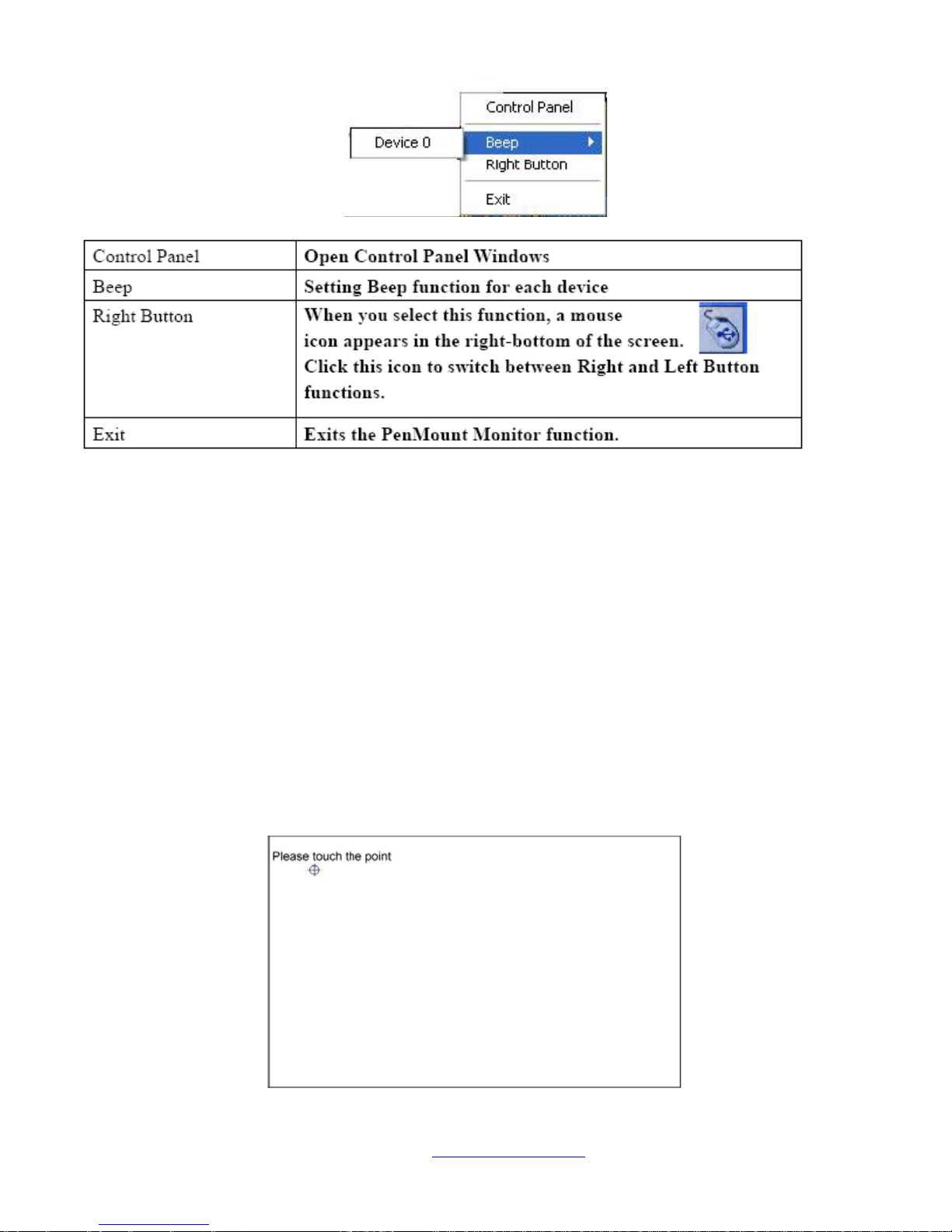
PenMount Monitor Menu Icon
The PenMount monitor icon (PM) appears in the menu bar of Windows 2000/XP system when you
turn on PenMount Monitor in PenMount Utilities.
Page 84
NVHMI SERIES User Manual www.nemavision-ipc.com
84
PenMount Monitor has the following function
PenMount Rotating Functions
The PenMount driver for Windows 2000/XP supports several display rotating software packages.
Windows Me/2000/XP support display rotating software packages such as:
• Portrait’s Pivot Screen Rotation Software
• ATI Display Driver Rotate Function
• nVidia Display Driver Rotate Function
• SMI Display Driver Rotate Function
• Intel 845G/GE Display Driver Rotate Function
Configuring the Rotate Function
1. Install the rotation software package.
2. Choose the rotate function (0°, 90°, 180°, 270°) in the 3rd party software. The calibration screen
appears automatically. Touch this point and rotation is mapped.
NOTE: The Rotate function is disabled if you use Monitor Mapping
Page 85
NVHMI SERIES User Manual www.nemavision-ipc.com
85
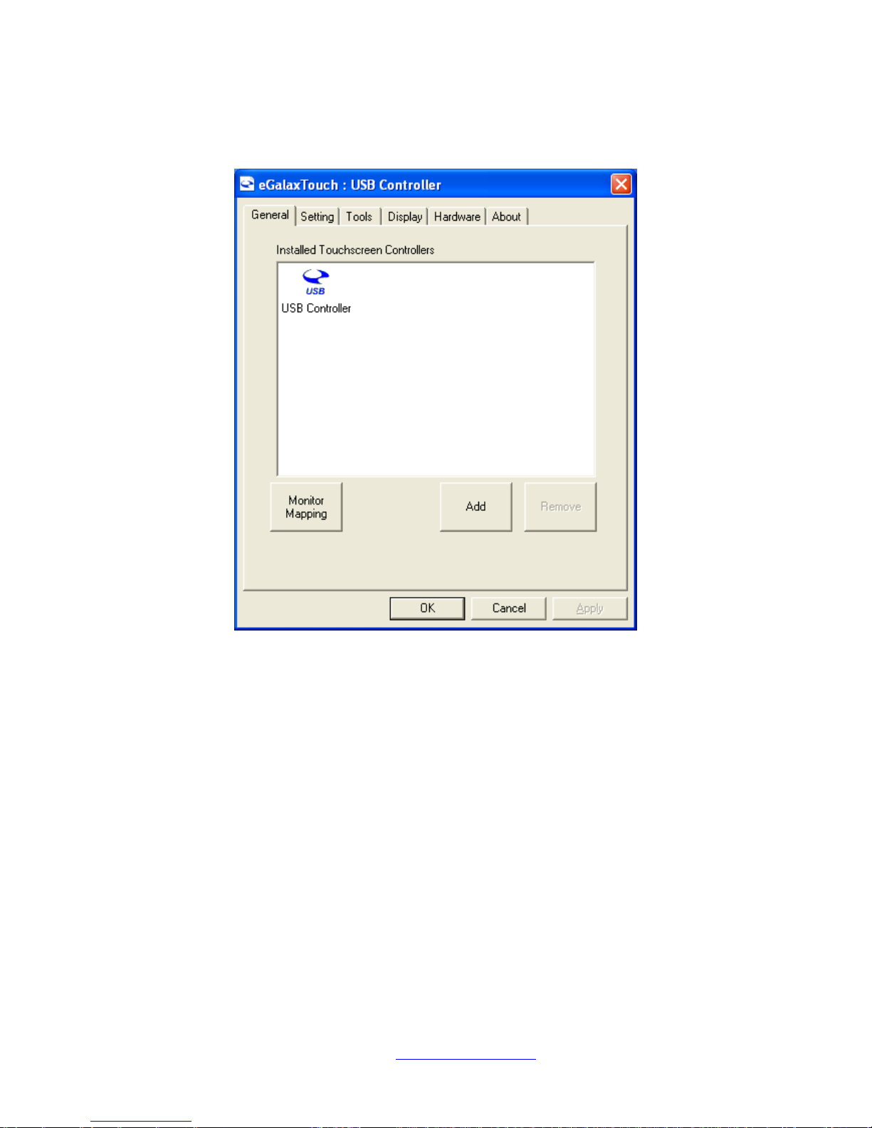
5.2.2 Software Functions(Projected Capacitive)
General
In this window, you can see there is USB Controller. Click OK to continue.
Monitor Mapping
to adjust touch panel
Add
to seNVh for device
Page 86
NVHMI SERIES User Manual www.nemavision-ipc.com
86
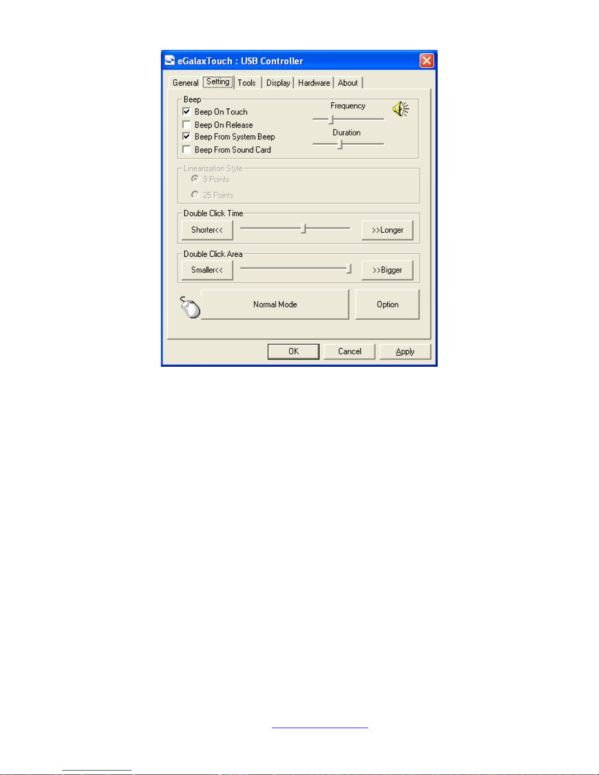
Setting
Beep
Beep On Touch
Beep On Release
Beep From System Beep
Beep From Sound Card
Linearization Style
9 points
25 points
Double Click Time
Shorter
Longer
Double Click Area
Smaller
Bigger
Normal mode
Simulate the mouse mode
Page 87
NVHMI SERIES User Manual www.nemavision-ipc.com
87
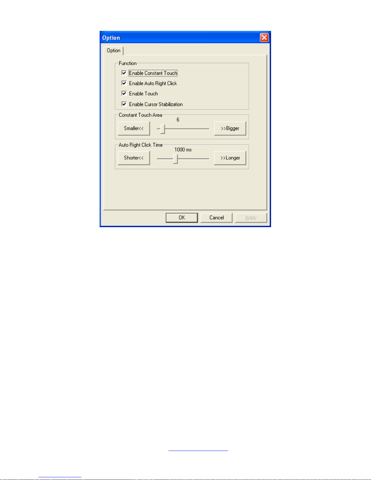
Option
Function
Enable Constant Touch
Enable Auto Right Click
Enable Touch
Enable Cursor Stabilization
Constant Touch Area
Auto Right Click Time
Page 88
NVHMI SERIES User Manual www.nemavision-ipc.com
88
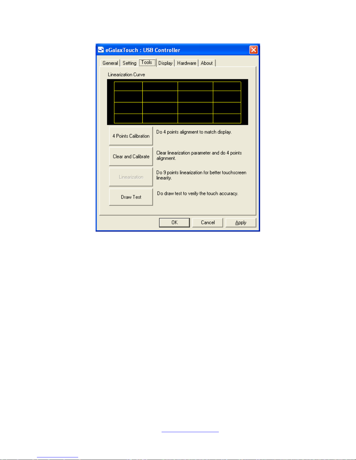
Tools
Click OK to continue the settings.
4 Points Calibration
Do 4 points alignment to match display.
Clear and Calibrate
Clear linearization parameter and do 4 points alignment.
Linearization
Do 9 points linearization for better touchscreen linearity.
Draw Test
Do draw test to verify the touch accuracy.
Page 89
NVHMI SERIES User Manual www.nemavision-ipc.com
89
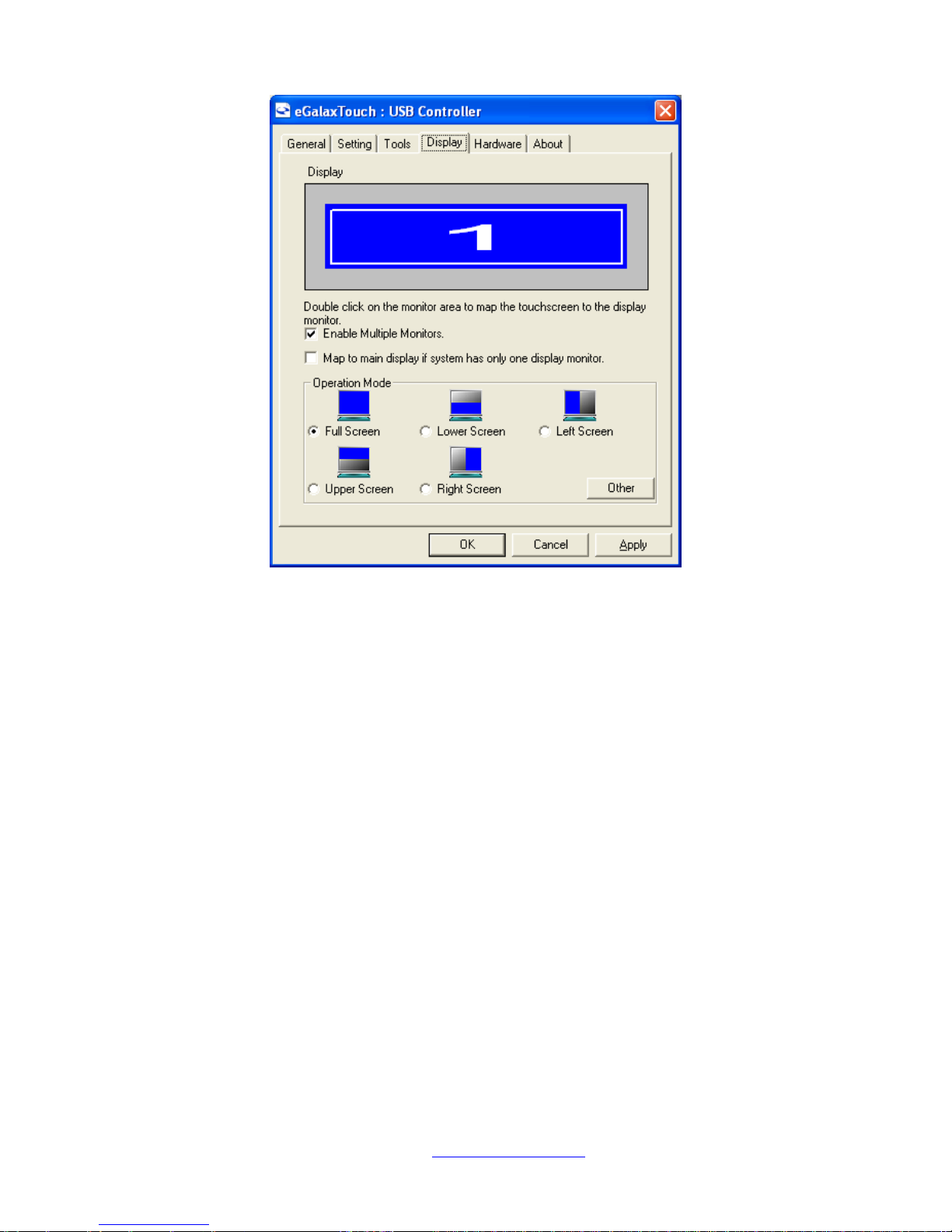
Display
In this window, it shows the mode of display.
Enable Multiple Monitors.
Map to main display if system has only one display monitor
Full Screen
Lower Screen
Left Screen
Upper Screen
Right Screen
Page 90
NVHMI SERIES User Manual www.nemavision-ipc.com
90
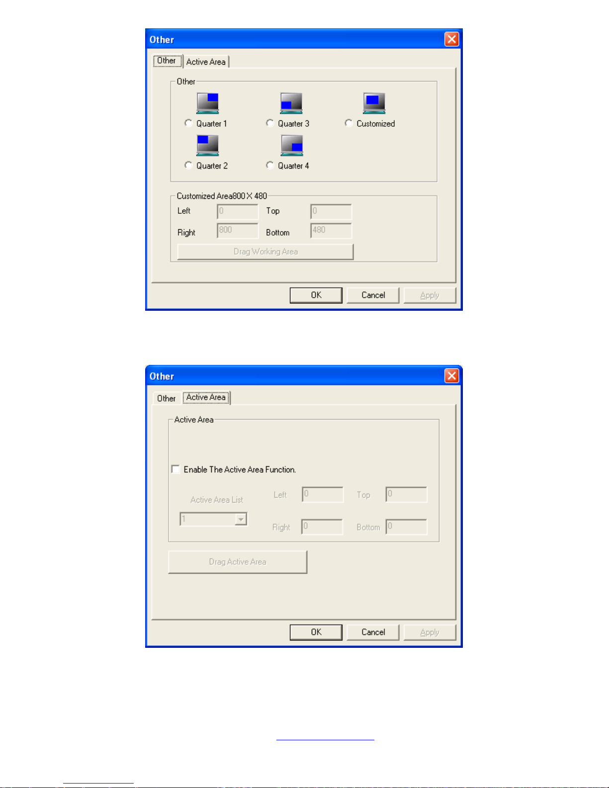
Other
Other mode of display. Quarter1~4 and Customized area.
Active Area
Drag active area to enable Active Area Function.
Page 91
NVHMI SERIES User Manual www.nemavision-ipc.com
91
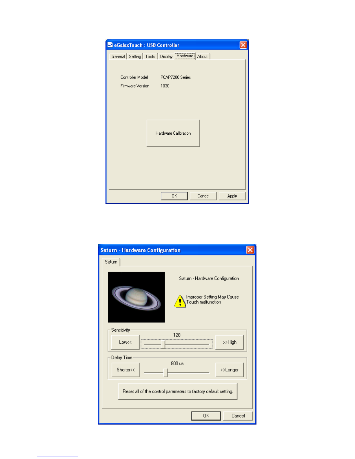
Hardware
Saturn Hardware Configuration
Page 92
NVHMI SERIES User Manual www.nemavision-ipc.com
92
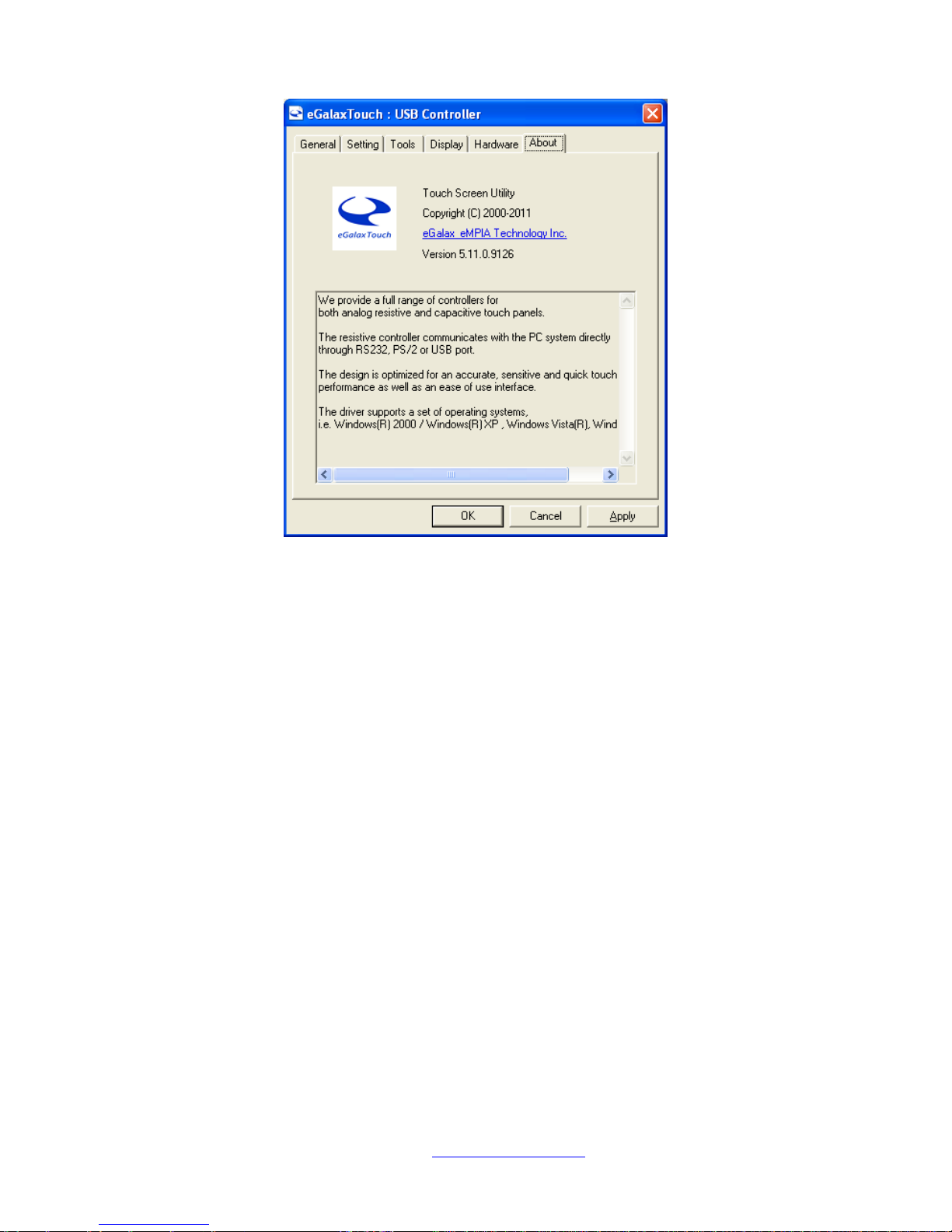
About
To display information about eGalaxTouch and its version.
 Loading...