

Page 1
™
•
NELSON
TYPE HLT SELF-REGULATING HEATER CABLE INFORMATION
SPECIFICATION/APPLICATION
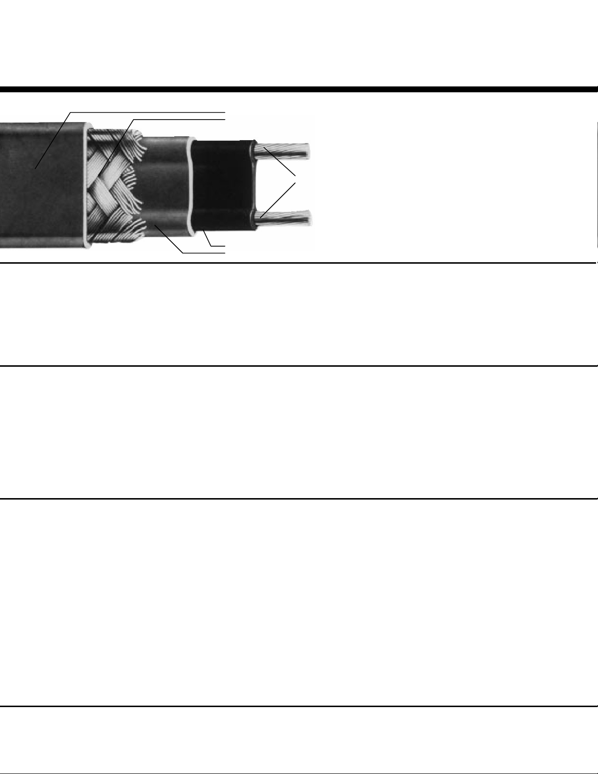
• Optional Fluoropolymer Overjacket
• Standard Metal Braid
Stranded Nickel Plated Copper Conductors
• Self Regulating Conductive Core
• Outer Fluoropolymer Jacket
HLT3-CB HLT23-CB
HLT5-CB HLT25-CB
HLT8-CB HLT28-CB
HLT10-CB HLT210-CB
HLT12-CB HLT212-CB
HLT15-CB HLT215-CB
HLT18-CB HLT218-CB
HLT20-CB HLT220-CB
Description:
Nelson’s Type HLT self-regulating
heater cable is a parallel circuit electric
heater strip. A conductive fluoropolymer
core material is extruded over the multistranded, nickel-plated, 16-gauge
copper bus wires. A fluoropolymer jacket
provides excellent dielectric strength,
moisture resistance, protection from
impact and abrasion damage, and a
wide range of chemical resistance.
A stranded tinned copper metal
braid is supplied on all heaters.
An optional fluoropolymer overjacket can
be specified when the heater cable is to
be installed in wet or corrosive
environments.
Operating Principle:
The parallel bus wires apply voltage
along the entire length of the heater
cable. The conductive core provides a
continuous parallel heating element
permitting the cable to be cut to any
length in the field with no dead or cold
zones developing. The heater cable
derives its self-regulating characteristic
from the inherent properties of the
conductive core material. As the core
material temperature increases, the
number of conductive paths in the core
material decreases, automatically
decreasing the heat output. As the
temperature decreases, the number of
conductive paths increases, causing the
heat output to increase. This occurs at
every point along the length of the cable,
adjusting the power output to the varying
conditions along the pipe.
The self-regulating effect allows the
cable to be overlapped without creating
hot spots or burnout. As the cable selfregulates its heat output, it limits the
maximum sheath temperature, while
also providing useful power for process
temperature maintenance
Application:
Nelson's Type HLT self-regulating Options: (Delete -CB and add) D1- Approved for use in Class I, Division
heater cable is ideal for maintaining fluid -J A tinned copper metal braid with a 1, Groups B, C and D hazardous
flow over a wide range of operating fluoropolymer overjacket is areas. Standard construction utilizes
temperatures. The product is used for available for use when the heater a tinned copper metal braid with a
freeze protection of periodically steam cable is exposed to excessive fluoropolymer overjacket. D1(200 psig) cleaned pipes and temperature moisture, organic chemicals, heating cable requires the use of
maintenance for 250°F (121°C) or lower solvents, etc. in hazardous HASK series conn ection kits and
processes. Typical applications include (classified) areas and ordinary Ground Fault Protection Devices
hydrocarbon and chemical product piping. areas. must be used on each heater
The base product is supplied with a circuit. All Division 1 designs must
tinned copper metal braid that may be used be reviewed by Nelson before
in both general applications and in dry, being installed.
non-corrosive hazardous (classified)
areas. It is also used to provide a
conductive ground path when cable is
installed on non-conductive surfaces,
such as plastic or painted pipe.
Page 2
™
NELSON
TYPE HLT SELF-REGULATING HEATER CABLE INFORMATION
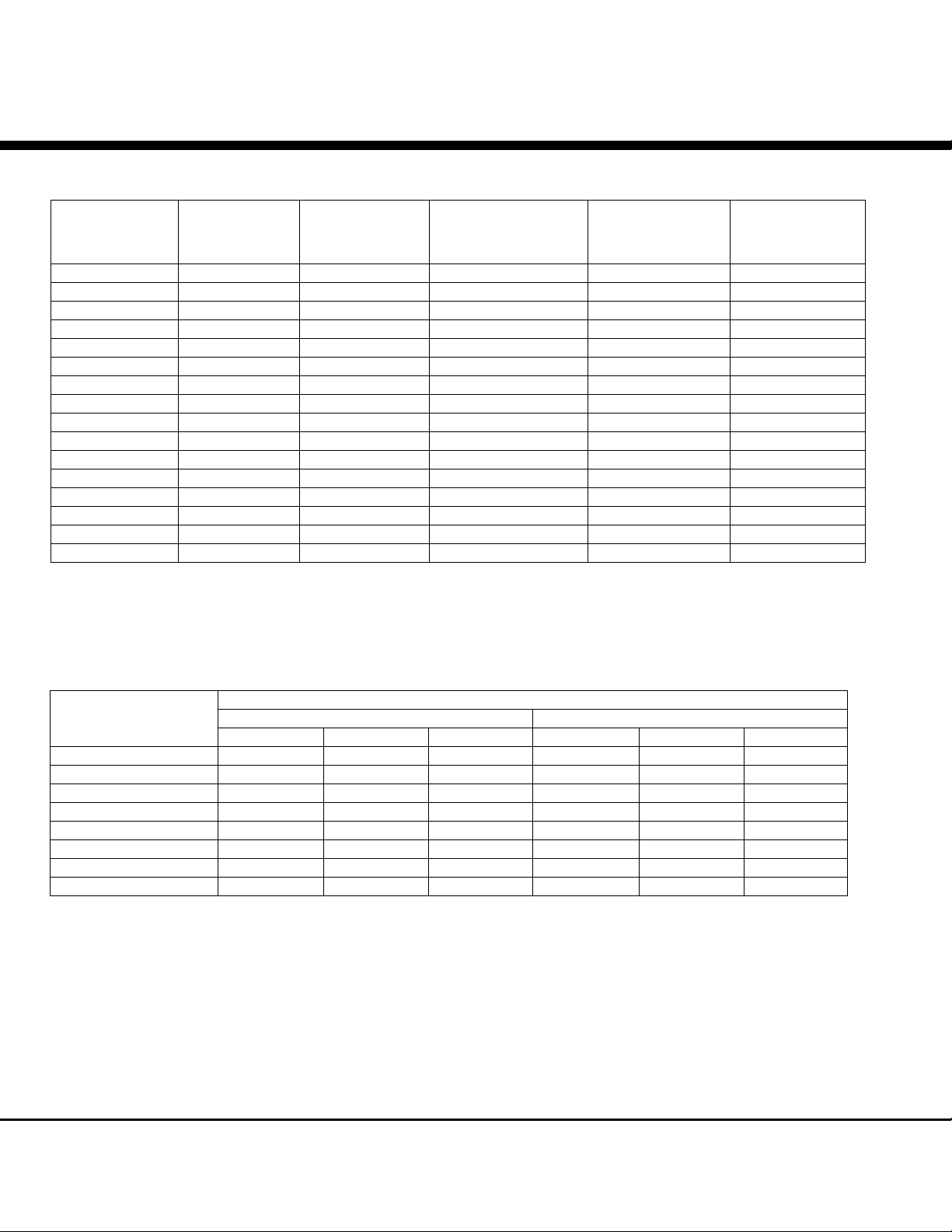
Performance and Rating Data:
SPECIFICATION/APPLICATION
Catalog
Number
HLT3 120 395 250°F (121°C) 375°F (191°C) T3 (T3)
HLT23 240 785 250°F (121°C) 375°F (191°C) T3 (T3)
HLT5 120 310 250°F (121°C) 375°F (191°C) T3 (T3)
HLT25 240 620 250°F (121°C) 375°F (191°C) T3 (T3)
HLT8 120 225 250°F (121°C) 375°F (191°C) T3 (T3)
HLT28 240 460 250°F (121°C) 375°F (191°C) T3 (T3)
HLT10 120 190 250°F (121°C) 375°F (191°C) T3 (T3)
HLT210 240 375 250°F (121°C) 375°F (191°C) T3 (T3)
HLT12 120 170 250°F (121°C) 375°F (191°C) T3 (T3)
HLT212 240 335 250°F (121°C) 375°F (191°C) T3 (T3)
HLT15 120 135 250°F (121°C) 375°F (191°C) T3 (T3)
HLT215 240 270 250°F (121°C) 375°F (191°C) T3 (T3)
HLT18 120 125 250°F (121°C) 375°F (191°C) T3 (T3)
HLT218 240 245 250°F (121°C) 375°F (191°C) T3 (T3)
HLT20 120 105 250°F (121°C) 375°F (191°C) T3 (T2D)
HLT220 240 210 250°F (121°C) 375°F (191°C) T3 (T2D)
* Electrical equipment T-rating codes define the maximum surface temperature that equipment will reach . It is used in
hazardous (classified) area applications. Parenthesized T-ratings are determined at a 20% over voltage required for
Class I, Division 1 applications.
Service
Voltage
Maximum
Length
Maximum
Maintenance
Temperature
Maximum
Intermittent
Exposure
T-Rating*
Circuit Breaker Selection:
Max. Length (Feet) Vs. Circuit Breaker Size
120 Volt 240 Volt
Watts/Ft. 15A 20A 30A 15A 20A 30A
3 295 395 585 785
5 185 245 310 385 500 620
8 145 195 225 290 390 460
10 115 150 190 225 300 375
12 98 130 170 195 260 335
15 80 110 135 160 215 270
18 70 95 125 140 185 245
20 65 85 105 125 170 210
NOTES:
1. Circuit breakers are sized per national electrical codes and are based on start-up temperatures between -20°F (-29°C) and 50°F
(10°C).
2. When using 240 volt product at 208, 220 or 277 volts, use the circuit adjustment factors shown in the Voltage Adjustment Table.
3. When using 2 or more heater cables of different wattage ratings in parallel on a single circuit breaker, use the 15A column
amperage of 15 amps, divide it by the maximum footage to arrive at an amps/foot figure for each cable. You can then calculate
circuit breaker sizes for these combination loads. These amps/foot factors include the 125% sizing factor.
4.National electrical codes require ground-fault equipment protection for each branch circuit supplying electric heating equipment.
Exceptions to this requirement can be found in the 2002 N.E.C.
5. Heater cables with D1 -optional construction require the use of a ground fault interrupter/ground leakage device with a trip setting
no greater than 30mA.
Page 3
™
NELSON
TYPE HLT SELF-REGULATING HEATER CABLE INFORMATION
SPECIFICATION/APPLICATION
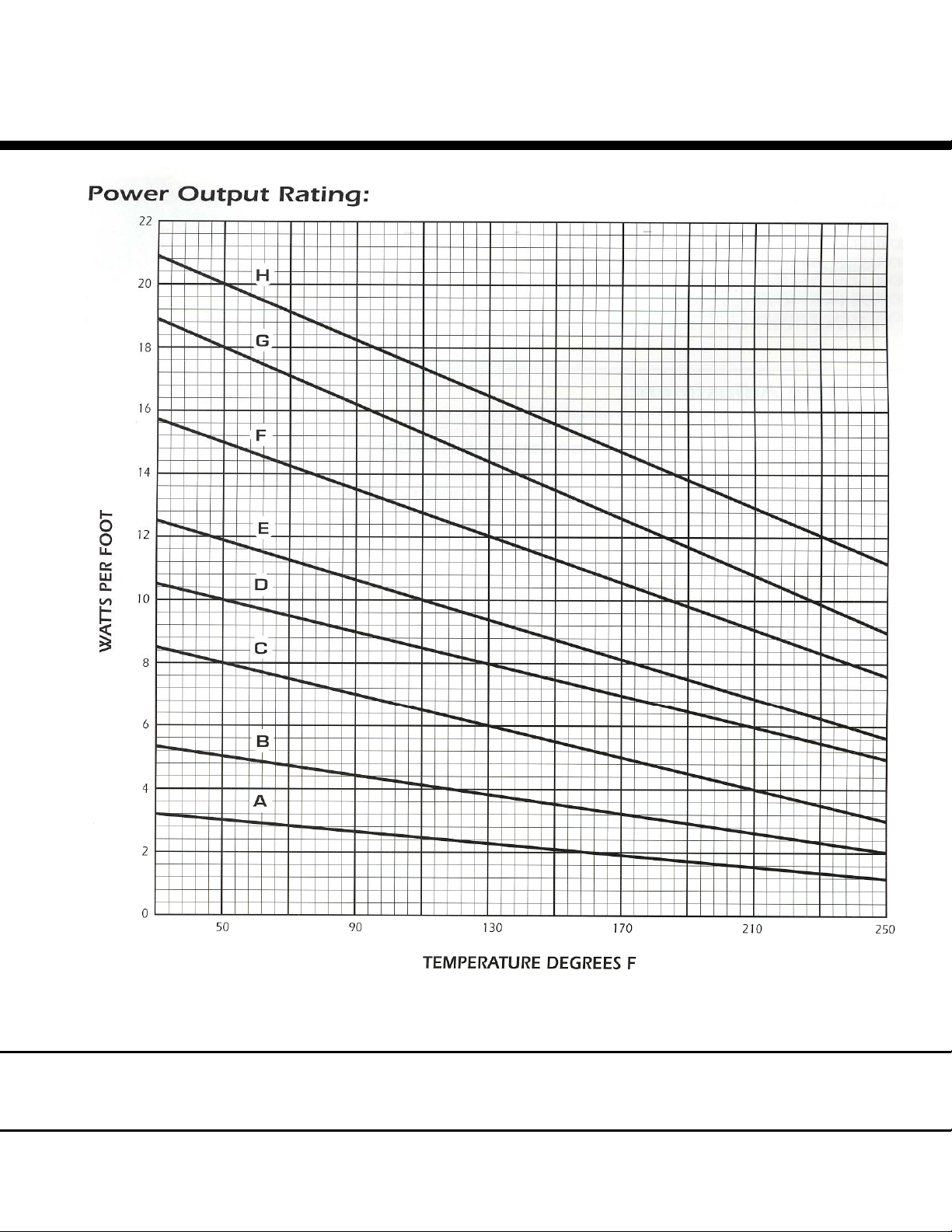
(10) (32) (54) (77) (99) (121)
(c)
A HLT3 B HLT5 C HLT8 D HLT10 E HLT12 F HLT15 G HLT18 H HLT20
HLT23 HLT25 HLT28 HLT210 HLT212 HLT215 HLT218 HLT220
WATTS PER FOOT x 3.28 = WATTS PER METER
PIPE TEMPERATURE °F CONVERSION TO °C = 5/9 (°F – 32)
Page 4
™
NELSON
TYPE HLT SELF-REGULATING HEATER CABLE INFORMATION
SPECIFICATION/APPLICATION
Catalog Numbers:
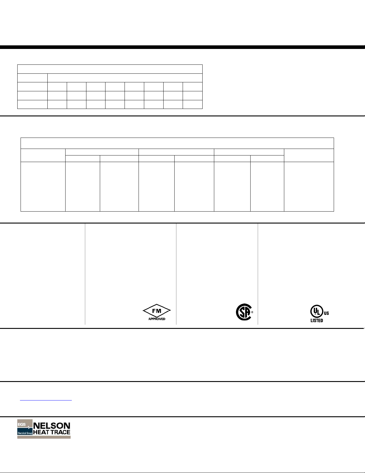
BASIC CATALOG NUMBERS
Watts Per Foot
Voltage
120 VAC
240 VAC
3 5 8 10 12 15 18 20
HLT3 HLT5 HLT8 HLT10 HLT12 HLT15 HLT18 HLT20
HLT23 HLT25 HLT28 HLT210 HLT212 HLT215 HLT218 HLT220
Standard Feature Suffix:
-CB Tinned Copper Braid
Optional Features Suffix:
-J Tinned Copper Braid and Fluoropolymer Overjacket
D1- Class I, Division I, Groups B, C and D approved
Voltage Adjustment:
Use of self-regulating products at other than rated voltages require minor adjustments in po wer and maximum circuit le ngths.
ADJUSTMENT MULTIPLIER
208 VAC 220 VAC 277 VAC Absolute
Product Power Length Power Length Power Length Max Length
HLT23 .74 .93 .84 .96 1.30 1.07 785 ft.
HLT25 .76 .93 .85 .96 1.29 1.07 620 ft.
HLT28 .78 .93 .86 .96 1.25 1.07 460 ft.
HLT210 .80 .93 .88 .96 1.23 1.07 375 ft.
HLT212 .81 .93 .88 .96 1.21 1.07 335 ft.
HLT215 .83 .93 .89 .96 1.19 1.02 270 ft.
HLT218 .85 I.01 .91 1.00 1.18 1.00 245 ft.
HLT220 .88 I.00 .93 1.00 1.15 1.00 210 ft.
Approvals:
FM
Ordinary Locations -
(-CB or -J options)
Hazardous (Classified)
Locations
(-CB or -J options)
Class I, Division 2
Groups B, C, D
Class II and III, Division 2
Group G
Class III, Division 2
(-J option)
Class I, Zone 1
Group IIC
(D1 option)
Class I, Division 1
Groups B,C, D
Class I, Zone 1
Group IIB
CSA
Ordinary Locations-
(-CB or -J options)
Hazardous (Classified)
Locations
(-CB or -J options)
Class I, Division 2
Groups B, C, D
Class II, Division 2
Groups E, F, G
(-J option)
Class I, Division 1
Groups B, C, D
Class II, Division 1
Groups E, F, G
Class I, Zone 1
Group IIB + H2
Zone 1, Ex e II T3
UL
Ordinary Locations-
(-CB or -J options)
Hazardous (Classified)
Locations
(-CB or -J options)
Class I, Division 2
Groups A, B, C, D
Class II, Division 2
Groups F, G
Class III, Division 2
(-J option)
Class I, Zone 1 and 2
Group IIC
(D1 option)
Class I, Division 1
Groups B, C, D
Class II, Division 1
Groups E, F, G
Class III
Accessories:
• Connection Kits for Power Connection, Tee Splice, Splices and End Seals (Nelson PLT and ALT Series)
• Thermostatic Controls (Nelson TA, TH, TE and HC Series)
• Junction Boxes, Tapes and Warning Signs
• Custom Control, Monitoring and Power Panels
• Division 1 Connection Kits for Power Connection, Tee Splice, Splice and End Connection (Nelson HASK Series)
• Zone 1 Connection Kits for Power Connection, Tee Splice, Splice and End Connection (Nelson Z1-PLT & Z1-ALT Series)
Nelson Heat Tracing Systems products are supplied with a limited warranty. Complete Terms and Conditions may be found on Nelson's website at
www.nelsonheaters.com.
NELSON HEAT TRACING SYSTEMS • P.O. BOX 726 • TULSA, OK 74101 • 918-627-5530 • FAX 918-641-7336 • www.nelsonheaters.com 314-SA-001
© 2006 Nelson Heat Tracing Systems May 2006
 Loading...