


CM2001
HEA T TRACING CONTROL
OPERA TOR’S MANUAL

CM2001 Contents
1 Product Overview......................................................................................................... 1.1
Introduction ..............................................................................................................................................1.1
Specifications...........................................................................................................................................1.2
Summary of Features ..............................................................................................................................1.3
Use of this Manual ...................................................................................................................................1.3
Conventions .............................................................................................................................................1.3
Shipping Content......................................................................................................................................1.3
Theory of Operation ................................................................................................................................. 1.4
2 Installation .................................................................................................................... 2.1
Unpacking the Controller..........................................................................................................................2.1
Control Module.........................................................................................................................................2.1
Mounting the Controller ............................................................................................................................ 2.3
Wire Sizing...............................................................................................................................................2.3
Conduit and Cabling.................................................................................................................................2.3
Power Wiring ...........................................................................................................................................2.3
Heater Wiring...........................................................................................................................................2.3
Ground Connection .................................................................................................................................. 2.3
RTD Sensor Wiring.................................................................................................................................. 2.3
Communication Wiring.............................................................................................................................2.4
Alarm Wiring ............................................................................................................................................ 2.4
3 Getting Started.............................................................................................................. 3.1
Introduction .............................................................................................................................................. 3.1
Enabling the Heater .................................................................................................................................3.1
Entering Setpoints....................................................................................................................................3.1
Testing Heater & Alarms...........................................................................................................................3.3
Monitoring System Status.........................................................................................................................3.4
4 Front Panel Operation.................................................................................................. 4.1
Overview ..................................................................................................................................................4.1
Operating the Keypad ..............................................................................................................................4.1
St atus Lights.............................................................................................................................................4.1
Alphanumeric Display .............................................................................................................................. 4.1
Keypad.....................................................................................................................................................4.1
Display Contrast.......................................................................................................................................4.1
Heater Numbering....................................................................................................................................4.1
St artup Messages .................................................................................................................................... 4.3
St atus Messages...................................................................................................................................... 4.3
Flash Messsages .....................................................................................................................................4.4
5 Measured Values .......................................................................................................... 5.1
Overview ....................................................................................................................... ........................... 5.1
Operating ................................................................................................................................................. 5.2
Statistics...................................................................................................................................................5.3
6 Setpoint Values............................................................................................................. 6.1
Overview ..................................................................................................................................................6.1
Setpoints Entering....................................................................................................................................6.2
Setpoint Access Security .......................................................................................................................... 6.2
Operating ................................................................................................................................................. 6.2
Heater Setup............................................................................................................................................6.5
System Setup...........................................................................................................................................6.8
Setpoint Tests......................................................................................................................................... 6.11

ContentsCM2001
7 Alarms ........................................................................................................................... 7.1
Overview ..................................................................................................................................................7.1
Trip or Failure Alarms ............................................................................................................................... 7.1
Process Alarms ........................................................................................................................................ 7.2
Warning Alarms........................................................................................................................................7.3
Reset Alarms............................................................................................................................................7.3
8 Communications .......................................................................................................... 8.1
Overview ..................................................................................................................................................8.1
Physical Layer..........................................................................................................................................8.1
Modbus Protocol ......................................................................................................................................8.2
Modbus Memory Map ..............................................................................................................................8.4
Modbus Map Data Format .......................................................................................................................8.6
9 Commissioning ............................................................................................................ 9.1
Overview ..................................................................................................................................................9.1
Requirements........................................................................................................................................... 9.1
RTD Input Test .........................................................................................................................................9.1
Heater Volt age and Current Test ..............................................................................................................9.2
Ground Fault Current Test........................................................................................................................9.3
Alarm Output Test ....................................................................................................................................9.3
Override Input Test...................................................................................................................................9.4
Placing the Controller in Service ..............................................................................................................9.4
Completing the Installation ....................................................................................................................... 9.6
Warranty
The manufacturer warrants each control that it manufactures to be free from
defective material or workmanship for a period of 12 months from date of
purchase.
Under this warranty , the obligation of the manufacturer is limited to repairing
or replacing the defective control at its option, when returned to the manufacturer’s factory with shipping charges prepaid.
If failure has been caused by misuse, incorrect application or alteration of the
control, this warranty will be void.
UNLESS SPECIFICALLY PROVIDED FOR IN WRITING IN THIS WARRANTY, EACH CONTROL IS PROVIDED WITHOUT ANY WARRANTY OF
ANY KIND EITHER EXPRESSED OR IMPLIED. IN PARTICULAR, WITHOUT LIMITING THE GENERALITY OF THE FOREGOING, THE FOLLOWING IMPLIED WARRANTIES AND CONDITIONS ARE EXPRESSLY DISCLAIMED:
a). ANY IMPLIED WARRANTY OR CONDITION THA T THE CON-
TROL WILL MEET YOUR REQUIREMENTS.
b). ANY IMPLIED WARRANTY OR CONDITION THA T THE OP-
ERA TION OF THE CONTROL WILL BE UNINTERRUPTED OR
ERROR FREE; AND
c). ANY IMPLIED WARRANTY OR CONDITION OF
MERCHANT ABILITY OR FITNESS FOR A PARTICULAR
PURPOSE.
The user shall be made aware that if the equipment is used in a manner not
specified by the manufacturer, the protection provided by the equipment may
be impaired.

CM2001
Introduction
The CM2001 single-point heat tracing controller uses a
microprocessor and is intended for stand-alone heat trace
applications. It can be for use with mineral-insulated, selfregulating or constant-wattage cable for freeze protection,
process control and instrument tracing. The CM2001 is
intended for indoor or outdoor installations in ordinary or
hazardous locations.
CM2001 offers many advantages over other heat tracing
control schemes, which generally use some combination
of mechanical thermostats, custom-built panels or programmable controls to provide control, monitoring and
alarm functions. Budgetary constraints usually limit the
degree of system fault monitoring to less than optimal
levels. This results in periodic costly process shutdowns
due to process or hardware malfunctions. Equipment
reliability concerns often force plant procedures to
include annual thermostat performance checks to ensure
that the device is still operating as intended. This can be
a tedious, labour intensive job.
Chapter 1
A controller is mounted near the pipe being traced to
monitor the heater point. This controller can communicate with a single master unit to give complete system
monitoring and control from a convenient location. Up to
32 controllers can be monitored on a RS485 data highway
to a centrally located master. By connecting controls to a
data highway , the CM2001 can immediately flag alarms
caused by heat tracing malfunctions, altered setpoints and
monitor actual values from a central location. Each local
control is completely independent and will continue to
function if the master fails or if the communication link
fails. This ensures maximum reliability and minimizes
vulnerability in the event of a hardware failure. Additional points can easily be added at any time as easily as a
mechanical thermostat can be installed. Unlike control
schemes using programmable controllers, no software
development is required. The complete system is operational as soon as it is installed.
Product Overview
Figure 1.1 Typical CM2001 Installation
1.1

CM2001
Chapter 1
Product Overview
Specifications
Temperature Input
Range: -50 to +500°C (-58 to 932°F)
Accuracy: ±2°C
Repeatability: ±1°C
RTD: Two, 100 ohm platinum, 3-wire RTD
20 ohms maximum lead resistance
Heater Switching
Configuration: -S1 single pole or -S2 two pole
dual SCR per phase
800 amp 1 cycle inrush
Ratings: 85-280Vac, 30A continuous
Line Frequency: 50 or 60Hz
Current Measurement: 0.1 to 30A 3%±0.2A
GF Measurement: 10 to 1000mA 5%±2mA
Voltage Measurement: 0 to 300Vac 3%±2V
Control Power
Power Requirement: Control power from heater voltage
85-280VAC, 10VA max
Protection: Control power from heater voltage
protected by 2A fuse
MOV transient protection
Communications
Port: (1) Serial network connection
Type: RS485
Protocol: Modbus® RTU.
Transmission Rate: 600,1200, 2400, 4800, 9600 baud.
Interconnect: 2-wire, shielded, twisted pair.
Highway Distance: 4,000 feet without repeater.
Modules per Highway: 32 Control Modules.
Measured Values
Temperature: -50 to 500°C (-58 to 932°F)
Minimum Temperature: -50 to 500°C (-58 to 932°F)
Maximum Temperature: -50 to 500°C (-58 to 932°F)
Heater Current: 0.1 to 60A
Ground Fault Current: 10 to 1000mA
Min. Heater Voltage: 85 to 300Vac
Max. Heater Voltage: 85 to 300Vac
Power Consumption: 0 to 1,000 MWh
Operating Cost: 0 to $1,000,000.00
User Interface
Display: 16-character x 2-line LCD Alpha-
numeric display
Keypad: 9 tactile keys, polyester faceplate
- Setpoint, actual, status
- Message Up, Message Down
- Value Up, Value Down
- Reset
- Enter
Contrast: Adjustable by potentiometer
Panel Indicators: Power on
Heater on
Serial communication active
System fail
Process alarm
Security: Controller parameters password protected
Environment
Approvals: CSA NRTL/C and FM
Class I, Div. 2, Groups A,B,C,D
Class I, Zone 2, Groups IIC
Class II, Div. 1, Groups E,F and G
Class III
Operating Temperature: -40°C to +50°C
Conformal Coating: Boards conformal coated for hostile
environments
Enclosure
Type: Nema-4X
Material: -N4XS stainless steel painted black
-N4X steel painted black
Size: 10”Hx8”Wx6”D
Features: Quick release latches to open door
Flat aluminum plate to act as heatsink
and mounting flange for mounting on
Uni-Strut.
One 3/4” conduit knockout for power
and three 1/2” conduit knockouts for RTD
and signal wiring.
Alarm Output
Alarm: Programmable for NO or NC contacts
One DC opto-isolated contact
One AC triac contact
Alarm Rating: DC contact: 30Vdc/0.1A, 500mW max
AC contact: 12-240Vac@0.5A max
Alarm Output: LED Indicator: 5Vdc/50mA
Alarm Function
Temperature: High Temperature Alarm
Low Temperature Alarm
Current: Low Current Alarm
High Current Alarm
Ground Fault Current: Ground Fault Current Alarm
Ground Fault Current Trip
Voltage: High Voltage Alarm
Low Voltage Alarm
Hardware: Self-Check Failure
Switch Shorted
RTD Open
RTD Shorted
Continuity
User-Definable Options
Heater Status: Enable or Disable
Heater Name or Tag: 16 Character Alphanumeric
Temperature Units: °C or °F
Proportional Control: on or off
Deadband: 1 to 50C° (1 to 100F°)
PowerLimit: 0.1 to 30A, off
SoftStart: 10 to 999s, off
TraceCheck: 1 to 24hrs, off
Temperature Setpoint: -50 to 500°C (-58 to 932°F), off, none
High Temp Alarm: -50 to 500°C (-58 to 932°F), off
Low Temp Alarm: -50 to 500°C (-58 to 932°F), off
High Current Alarm: 0.1 to 30A, off
Low Current Alarm: 0.1 to 30A, off
Ground Fault Alarm: 10 to 1000mA, off
Ground Fault Trip: 10 to 1000mA
High Voltage Alarm: 85V to 300V, off
Low Voltage Alarm: 85V to 300V, off
RTD Definition: Single, Backup, Highest, Lowest,
Average or High Temperature Cutout
RTD Fail-safe: Heater On or Heater Off
Heat Trace Curve: disable, user, LT3, 5, 8, 10
HLT3, 5, 8, 10, 12, 15, 18, 20
Override: On or Off
Alarm Contacts: NO or NC for each contact
Alarm Light: Alarm on, Alarm off, Flash during alarm
then on, Flash during alarm then off
Ground Fault Trip
Maximum Trip Time: 3.7 seconds
1.2

CM2001
Summary of Features
Chapter 1
Product Overview
Inputs
2-RTD Sensors
1-Override
Monitoring
RTD Temperatures
Heater Current
Heater Voltage
GF Current
Alarms
Low and High Current
(Compensated by heat trace curve for
Self-regulating cable)
Low and High T emperatures
Continuity
GF Alarm
GF Trip
Switch Failure
Sensor Failure
Self-Test Failure
Outputs
1-AC Triac Contact
1-DC Opto-Isolated Contact
1-LED Alarm Indicator
Statistics
Minimum and Maximum T emperatures
Maximum Current
Maximum Ground Fault
Minimum and Maximum Voltage
Energy (MWh)
Energy Cost
Control
Temperature (On/Of f- Deadband)
Temperature -Proportional
PowerLimiting
Softstart
Early Warning (TraceCheck)
Low and High Current
Continuity
GF Alarm
GF Trip
Communications
1-RS485
Modbus Protocol
Environment
CSA Certified and FM Approved for Hazardous
Locations
W eatherproof, NEMA-4X Enclosure
-40°C to +50°C Operating Temperature Range
User Interface
32 Character LCD Display
LED Indicators on Faceplate
Clear, English Language Messages
Intuitive Message Structure
Tactile Keys
Access Security
Using This Manual
Detailed information relating to switch and output ratings,
accuracy and so forth are detailed in Chapter 1 Specifica-
tions. Chapter 2 Installation discusses important mounting and wiring issues for reliable operation. Chapter 3
Getting Started provides a step-by-step tutorial for a heat
trace application. The remainder of this manual should be
read and kept for reference to provide the maximum
benefit of the CM2001.
Conventions
The following conventions are used in this manual.
? User Changeable Values
& Retrieved Data
[ ] Key Press
Shipping Content
CM2001 Heat Trace Controller
CM2001 Instruction Manual with Warranty Card
1.3
CM2001
Theory of Operation
Controller functions are controlled by a Intel 80C32 8-bit
microprocessor that measures all analog signals and logic
inputs, control heater output and alarm contacts, and
reads all user input including communications and outputs
to the faceplate display and LEDs. Consult the hardware
block diagram in figure 1.8 for details. The remainder of
this chapter describes the algorithms and operation of
some of the controller functions.
RTD Sensing
Chapter 1
linearization algorithm.
Current, Ground Fault and Voltage Sensing
Current transformers and high impedance voltage dividers
are used to scale-down the incoming heater current,
ground fault current and voltage. All three signals are then
passed through a full wave rectifier and filter to obtain a
DC signal. The DC signals are then converted to digital
values by a 10 bit A/D converter before finally being
passed on to the CPU for analysis.
Product Overview
An RTD changes its resistance in a precision relationship
to temperature. This resistance is sensed by passing a
constant current through the RTD and measuring the
resulting voltage across the RTD (resistance = voltage/
current). The voltage appearing across RTD1 terminals
6&8 and RTD2 terminals 10&12 also includes the
resistance of the inter-connecting wiring to the R TD,
which varies with wire length, size and ambient temperature. By using a three-wire sensing scheme and a lead
resistance compensation circuit, the lead resistance is
cancelled out to give a voltage proportional to the true
R TD sensor temperature.
R TDs respond in a known but non-linear fashion to
temperature, which if uncorrected could lead to significant errors over the temperature range of the controller.
Consequently , some means is needed to convert the input
voltage to a linear and useful range. The CPU applies
gain, offset and non-linearity corrections through a
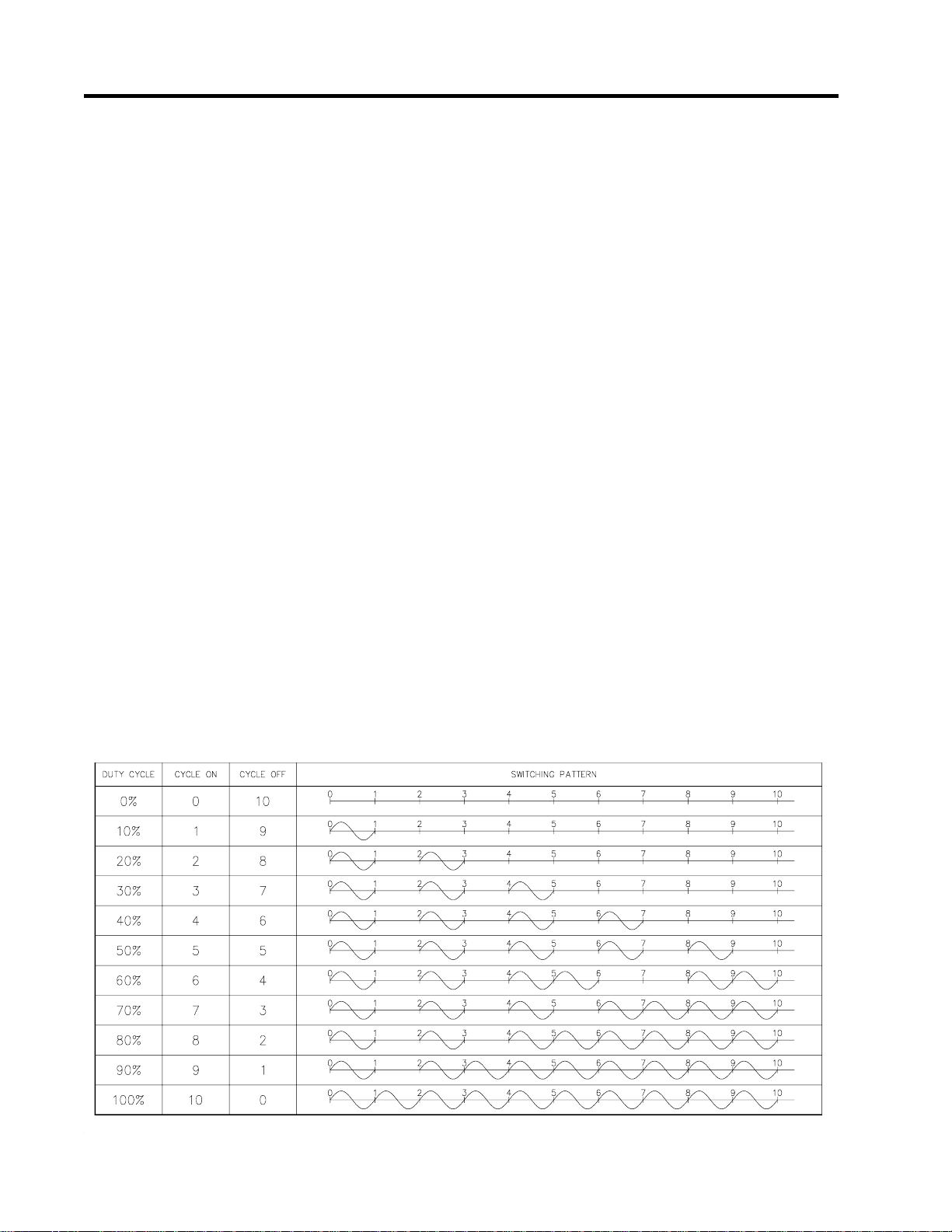
Figure 1.2 Cycle Modulation - 10 Cycle Frame
Each of the three DC signals are sampled 300 times with
zero cross synchronization so that the sampling covers an
exact span of ten power cycles. This is to ensure that
heater current values are consistently measured when the
heater output cycle is modulated by the powerlimit,
softstart or proportional control functions.
Powerlimit
The powerlimit function allows the heater to operate
below its rated power by cycle modulation. Cycle
modulation is accomplished by controlling the integral
number power cycles into the heater over a periodic time
frame. The CM2001 uses a ten cycle time frame. The
integral number of power cycles per time frame is called a
duty cycle. With a ten cycle time frame, there are ten duty
cycles possible. For each duty cycle, there is a fixed
pattern that defines the number of power cycles in which
the heater is on and off. This is shown in figure 1.2:
1.4

CM2001
Chapter 1
Product Overview
Cycle modulating the current through the heater has the
effect of turning the heater on and off rapidly and
therefore, power output is reduced in the long run. Since
the switching is zero-cross controlled, the controller
knows exactly when power cycles start and finish. Zerocross switching also helps reduce power harmonics that
generate unnecessary interference.
The heater current (average current) measured by the
controller while cycle modulation is in effect may be
approximated as follows:
Heater Current at 100% x Duty Cycle = Average Current
When powerlimit is enabled, a powerlimit current is set
by the user. This is essentially the desired average current.
The powerlimit control algorithm ensures that the actual
current will not exceed the powerlimit setting while
optimizing the maximum duty cycle possible. When the
average current exceeds the powerlimit setting, the duty
cycle is reduce by 10%. When the average current is
below the powerlimit setting, the duty cycle is increased
by 10%. Before the algorithm increases or decreases the
duty cycle, the controller waits until the heater current has
reached steady-state at the current duty cycle setting. If
the heater is initially off and the controller calls for heat,
the duty cycle starts at zero and increases by 10%
increments until it reaches a steady-state value. This
ramping up effect provides a current-driven softstart
whenever the controller calls for heat unlike the softstart
function, which is time driven.
Softstart
During cold temperature startups with self-regulating heat
trace cables, the current driven softstart built into the
powerlimit function may not be long enough to overcome
the inrush current. The softstart function is separate from
powerlimit and is time driven where for when you set the
softstart period. Having the two separate functions is
desirable when powerlimit may not be required by the
application but softstart is essential to avoid nuisance
breaker trips during cold startups. The controller applies
the softstart function initial startup when the controller is
powered up.
During controller power-up and assuming the controller is
calling for heat, the duty cycle starts at 10% and increments by 10% until full power is reached. Since there are
ten duty cycle increments, the time that the controller
maintains each duty cycle setting is the softstart setting
(softstart period) divided by 10. The softstart operation
powerlimit and proportional control off is shown by the
curve in figure 1.3.
Figure 1.3 Softstart Curve with Powerlimit and
Proportional Control Disabled
With powerlimit enabled, the only dif ference is that
instead of the duty cycle ramping to 100%, it stops at the
value determined by the powerlimit function such that the
average current does not exceed the powerlimit current
set by the user. The maximum duty cycle setting is
approximated by the controller initially so that the time
period for each duty cycle increment can be determined.
The softstart operation with powerlimit enable is shown
by the curve in figure 1.4.
Figure 1.4 Softstart Curve with Powerlimit Enabled
Operation of the softstart function varies depending on
whether or not powerlimit and/or proportional control are
enabled. When powerlimit and proportional control are
off, operation is simplified. The softstart function uses
cycle modulation to gradually increase power output over
the softstart period. Since most circuit breakers are the
thermal type, the cycle modulated output appears as a
reduced load to the circuit breaker.
When proportional control is turned on, the maximum
duty cycle available to the controller is constrained by the
powerlimit current if enabled and softstart.
1.5

CM2001
Proportional Control
Chapter 1
Product Overview
Unlike on/off control where the heater is fully on or off,
proportional control can partially turn on the heater. The
heater output is proportional to the difference between
actual temperature and heater setpoint. The relationship is
expressed as follows:
(actual temperature – heater setpoint) x k = heater output
where k is the proportional gain
T o partially turn on the heater, the proportional control
function uses cycle modulation in the powerlimit function.
By incorporating cycle modulation into the proportional
control equation, the algorithm is expressed using the
following equations:
0)(0)(
≤=
teiftd
)(
te
)(
td
DB(t)
<<=
≥=
=
td
cycleduty)(Where
tDB
Ts
T(t)
ÿTTs-T(t)e(t)
t
The deadband factor DB(t) is a time constant that
determines the slope of change of the proposed heater on
duty cycle with the temperature difference. It is adjusted
between 1 to 10 each hour to minimize the difference
between the measured temperature and the temperature
setpoint. Every hour after power up, the controller
calculates the absolute values of the temperature
differences e(t) and sums them during the hour. Then the
total absolute temperature difference is divided by the
number of temperature readings taken during the hour.
The result is called the Average Absolute Temperature
Difference (AATD) for the hour. If current AA TD is
smaller than the AATD in the previous hour , the deadband
factor will be increased or decreased in the same
direction. If current AATD is larger than the AA TD in the
previous hour, the deadband factor will be increased or
decreased in the reversed direction. At steady state, the
deadband factor used will fluctuate around a optimum
value.
=
secondsintime
)()(0
tDBteif
)()(1)(
tDBteiftd
°=
C)(peratureheater tem
°=
C)(
°==
cycle)C/duty(infactordeadband)(
C)(emperaturesetpoint theater
°=
Figure 1.5 shows the relationship between the proposed
heater on duty cycle and the temperature difference for
different deadband factors used.
Figure 1.5 Proportional Control
Duty Cycle vs. Temperature Difference
On/Off Control with Deadband
The default control mode of the controller is deadband
control or simply on/off control with the proportional
control setting turned off. On/off control without
deadband (that is deadband set to 0 C° or 0 F°; note that
these units denote the temperature differential with “°”
placed to the right of the unit) means that the heater turns
on when actual temperature is below setpoint and turns
off when above setpoint. However, this causes oscillations
when the actual temperature is very close to setpoint. To
eliminate oscillations, hysterisis is applied to the on/off
control by a deadband value. The on/off control with
deadband operation is described by the hysterisis curve in
figure 1.6. Assume that actual temperature is well below
(setpoint - deadband setting), the controller calls for heat.
As the actual temperature rises, the controller continues to
call for heat until the actual temperature has reached
(setpoint + deadband setting). The controller no longer
calls for heat and the heater is off. As the actual
temperature cools, the controller does not call for heat
until the actual temperature reaches (setpoint – deadband
setting). The hysterisis effect is controlled by the
momentum of the actual temperature rather than the
temperature value itself.
1.6

CM2001
Chapter 1
Product Overview
Figure 1.6 On/Off Control with Deadband
Heat Trace Curve
Monitoring low and high current alarms on self-regulating
heat tracing cable is difficult. Choosing a high current
alarm setting based on cable characteristics near the
heater setpoint temperature will produce nuisance alarms
during startup. Choosing a low current alarm setting other
than below the current draw of the cable at heater setpoint
temperature produces nuisance alarms. The heat trace
curve function allows you to program the cable characteristics so that the controller can offset the current alarm
settings.
Figure 1.7 Heat Trace Curve
The heat trace curve is described by the following linear
equation:
W = aT + b
where, W is the Watt/ft at temperature T (in degree F), a
and b are the slope and offset of the linear curve.
If the Watt per foot value of the heat trace is Ws at
setpoint temperature Ts, and the Watt per foot value of the
heat trace is W at temperature T, the offset ratio to be
applied to the high/low current alarm level is Ws/W.
That is, if the high/low current alarm level is set to Is, the
current draw of the cable at setpoint temperature of Ts,
then the high/low current alarm level at operating temperature T should be corrected to (Ws/W)*Is to compensate the effect of operating temperature on the allowed
maximum/minimum heater current. The heat trace curve
is shown in figure 1.7.
If no heat trace curve is used, the offset ratio is set to 1
and no correction to the high/low current alarm level is
done.
1.7

CM2001
Figure 1.8 Hardware Block Diagram
Chapter 1
Product Overview
1.8

CM2001
Unpacking the Controller
Chapter 2
Installation
Check the shipping cartons for damage, or other signs of
rough handling or abuse. If damaged, notify the shipping
carrier at once.
Carefully remove the CM2001 from the shipping box.
Save the packing materials in case the unit needs to be
transported at a later date.
Inspect face plate for damage and check electronics for
loose wiring or damage. Report any damage to the carrier
at once.
Control Module
See Figure 3.1 Main Board Layout and Figure 3.2 Power
Board Layout to locate the following:
•S1 Address Enable: When the switch is set to DIS, the
Module Number cannot be changed from a master on
the data highway. When set to EN, the Module Number
can be changed for the next two minutes from a master
on the data highway. During this time the ADDRESS
ENABLE light is on.
•S2 Program Enable: When the switch is set to DIS,
programming is disabled; setpoints and configuration
cannot be changed. When set to EN, programming is
allowed.
•S3 RS485-120: When the jumper is set to IN, the
RS-485 line is terminated by a 120 ohm resistor. Only
the last Control Module on the data highway should be
set to IN.
Terminals: Refer to Figure 3.1 Typical Wiring Diagram,
for power, heater and RTD field connections.
•T1 Alarm Contacts: The opto-isolated dc output is
rated 30 Vdc @ 0.1 A (terminals 22 and 23) and the
triac ac output is rated 240Vac@0.5A (terminals 20
and 21). Contacts are configurable for normally open
or closed.
•T2 Alarm Light Output: The output is configurable for
normally open, closed or flash. Output is rated 5 Vdc
@ 50 mA for an LED type lamp (terminals 18+ and
19-).
• T3 Override Input: W ith the Override function
(SETPOINTS\HEATER SETUP\OVERRIDE) set to
on, the heater output is affected by the override input.
When the terminals are open, the heater is forced off.
When the terminals are closed, the heater is controlled
by the RTDs unless the heater setpoint is set to of f. In
this case, the heater is solely controlled by the override
input. The logic of this input allows either ambient
temperature override or load shedding on multiple
controllers (terminals 24+ and 25-).
•T4 RTD1A and RTD1B Inputs: 3 wire RTD input.
Ground terminal connects to shield or case. Lead
resistance compensated. (terminals 6-13).
•T5 Earth Ground: (terminal 1).
•T6 Heater Power Input: 85-280Vac/30A max
continuous ( terminals 2 and 3).
•T7 Heater Power Output: 85-280Vac/30A max
continuous ( terminals 4 and 5).
•T8 Safety Ground: Terminate to ground stud. Termina-
tion of safety ground is required for transient protection circuit on RTD inputs and RS485 serial port to
operate properly (terminal 14).
Status Lights:
•L1 Power: Light is on when control power is present.
•L2 Address Enable: Light is on when controller is in
Address Enable mode. Light must be on to allow the
Module Number to be changed from a master on the
data highway.
•L3 Transmit: Flashes when data is being transmitted
from the serial port to the data highway.
•L4 Receive: Flashes when data is being received at the
serial port from the data highway .
•L5 Override: Light is on when the Override Input terminals are shorted.
Communication Ports:
•C1 Interface to Main/Power Board: Connector to
interconnect power and main board via ribbon cable.
•C2 Serial Port 1: Connection to an RS-485
data highway via a 2-conductor, shielded, twisted pair
cable. Maximum Cable length with 32 devices without
repeater is 4,000 feet. ( terminals 15+, 16-,17 SHD).
Warning - The ground fault trip function is
intended for equipment protection only and
should not be used in place of ground fault
protection for personnel protection where
this is required.
2.1

CM2001
Figure 3.1 Main Board Layout
Chapter 2
Installation
Figure 3.2 Power Board Layout
2.2
CM2001
Chapter 2
Installation
Mounting the Controller
Mount the control panel with Unistrut brackets using 1/2”
bolts. The Unistrut (or equivalent) mounting allows air
circulation to cool the heat-sink. This is important to
ensure proper operation of the CM2001. For optimum
readability, mount with the display at eye level and not
in direct sunlight. Mounting dimensions are shown in
Figure 3.6.
Wire Sizing
Wiring methods should comply with Canadian
Electrical or National Electrical Code and
local codes. Power and signal wires should not
be run in the same conduit system. Wiring
should be rated at least 90 °C.
)GWA(eziSeriW)A(daoLtnerruC
60305
80304
014205
216105
tneibmA.xaM
suitable for #10 stud.
Ground Connection
Connect the controller grounding stud directly to a ground
bus using the shortest, practical path. Use a tinned copper,
braided bonding cable such as Belden 8660. As a guideline, the ground cables should be minimum 96 strands,
number 34 AWG each.
The grounding is not only a safety requirement but is
necessary for the input transient protectors or the RTD
and communication inputs to work properly. The transient
protection network is grounded through terminal 14,
safety ground, which is bonded to the chassis ground stud.
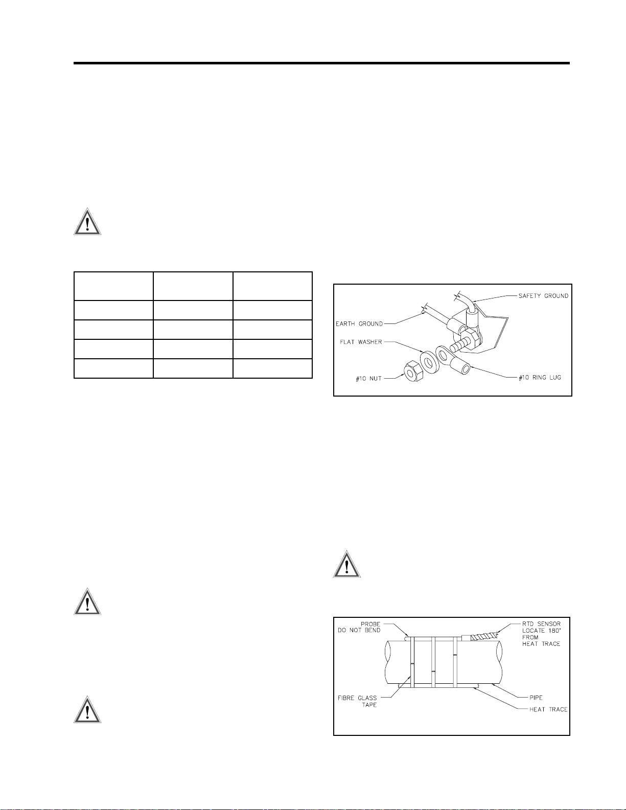
T o install the ground connection, remove the outside nut,
washer and #10 ring lug provided on the ground stud.
Crimp the ground cable onto the ring lug and re-assemble
Figure 3.3 Ground Connection
onto the ground stud using the washer and nut.
)C°(erutarepmeT
Conduit and Cabling
The CM2001 comes with one 3/4” and two 1/2” conduit
knockouts located on the bottom of the enclosure.
Conduit hubs should be NEMA-4X rated, such as T&B
H050-0.5 and H075-0.75 or Myers equivalent, to maintain a watertight seal. Unused knockouts should be sealed
using NEMA-4X rated seals.
Power Wiring
The power input terminals supply power to both the heat
trace and controller. Size power input wires appropriately
to the breaker size and maximum ambient operating
temperatures. Maximum breaker size is 30A. Connect
power wires to input terminals 2 and 3. See Figure 3.7.
The supply voltage must be within the power
supply range of 85-280Vac and rated voltage
range of the heat trace cable.
Heater Wiring
Connect heating cable wiring to terminals 4 and 5. See
Figure 3.7. If the heating cable has a braid, it should be
terminated to the ground stud using a ring terminal
RTD Sensor Wiring
R TD sensors should be 3-wire, 100 ohm, platinum to DIN
standard 43760. Mount the RTD element on the pipe,
away from the heat trace and 30° to 45° from the bottom
of the pipe. The total circuit resistance per conductor
from the RTD to the control panel must be less than 10
ohm. Exceeding this resistance will result in a non-linear
temperature measurement. Beldon cable 8770 or equivalent allows RTDs to be placed up to 1,000 feet from the
control panel. Complete all RTD wiring according to
Figure 3.6 Typical Wiring Diagram.
The RTD probe is delicate and should not
be bent or used as a tool to puncture
insulation.
Figure 3.4 RTD Mounting
Wiring methods must conform to Class I,
Division 2 or Class I, Zone 2 requirements.
2.3

CM2001
Chapter 2
Installation
You must install the RTD sensor on the pipe surface or
thermal well before the pipe insulation to ensure proper
thermal contact. The RTD position should be 180° from
the electric heat trace cable which is the coldest spot of
the pipe. The R TD sensor may be secured to the pipe by
fiber-glass tape. If additional wiring is required for the
R TD, shielded 3-lead wire sized 18 or 20AWG must be
used for the RTD sensor to minimize the effects of noise
pickup. A typical RTD installation is shown in Figur e 3.4.
Communication Wiring
The CM2001 is equipped with a communication port that
provides continuous monitoring and control from a
remote computer, SCADA system or PLC. Communications protocol is Modicon Modbus as discussed in the
communications chapter.
Communication is RS-485 mode where data transmission
and reception are done over a single twisted pair with
transmit and receive data alternating over the same pair of
wires.
Shielded twisted pair such as Beldon cable 9841 or
equivalent is recommended to minimize error from noise.
You must observe polarity. For each CM2001 controller,
you must connect A+ terminals together and B- terminals
together. The shield terminal (labelled SHD) connect to
shield wire of the cable.
T o avoid loop currents, the shield should be grounded at
one point only. Connect between controllers in daisychain fashion. The total length of this daisy-chain should
not exceed 4,000 feet. The maximum number of devices
connected is 32 to avoid exceeding driver capability. Y ou
can use commercially available repeaters to increase the
number of devices over 32. Avoid star or stub
connections.
T erminate the first and last device in the daisy-chain loop.
Each controller is equipped with a termination jumper as
shown in Figure 3.2.
The controller comes unterminated from the factory
(JP401 and JP402 in OUT position). If the controller is
the first or last device, it can be terminated by moving the
two jumpers (JP401 and JP402) to the IN position.
The communication port is powered by an isolated power
supply with opto-coupled data interface to eliminate noise
coupling. In addition, surge protection devices are
employed at the front end of the port to protect against
lightening strikes and ground surge currents. These may
cause large, momentary voltage differences between
devices on the data highway .
Alarm Wiring
The CM2001 has two passive alarm contacts and one
active alarm output for driving an LED alarm indicator.
Both the alarm contacts are software configurable for
normally open or closed. The alarm LED output is
software configurable for alarm on, alarm off or flash
during alarm. Refer to Figure 3.7 for alarm output
terminals.
The AC triac alarm output is rated 12-240Vac, 0.5A. The
DC alarm output is an opto-isolated transition output
rated 30Vdc/100mA, 500mW max.
The alarm LED output is rated 5Vdc, 50mA. It can drive
a 6Vdc LED indicator. Alarm outputs are designed for
interface to annunciator, panels, PLC or DCS.
Figure 3.5 Communication Wiring
2.4

DC ALM
Rev. 1
May, 2005

CM2001
Introduction
The CM2001 has many features that provide trouble-free
operation of heat tracing installations.
An example is presented to illustrate CM2001 setup and
operation on a specific installation. CM2001 is easy to
program and setting up a unit to your specific requirements should be straight forward.
In this example, a CM2001 will control a heavy feed line.
Chapter 3
Install and commission the control in the following order:
STEP 1: Enabling the heater
STEP 2: Entering setpoints
STEP 3: Testing heater and alarms
STEP 4: Monitoring system status
Enabling the Heater
Getting Started
Example: Heater will be programmed as:
Configuration:
1) 2 RTDs for temperature sensing
2) Mineral insulated (MI) cable is used for the heater.
3) Normally open alarm contact to remote programmable
control
4) Northern climate installation outdoors.
Operating temperatures: -40° to +40 °C
NEMA-4X weatherproof enclosure.
tniopteSderiuqeRegnaR
niatniamdiulF
erutarepmet
erutarepmetwoL
mrala
erutarepmethgiH
mrala
retaehlanimoN
tnerruc
retaehlanimoN
egatlov
pirttluafdnuorG
tnerruc
mralatluafdnuorG
tnerruc
esicrexemetsyS
lavretniemit
ttawoliKreptsoC
ruoh
emanretaeHLIOYVAEH
F°221ffo/F°239ot85-
enon/
F°59ffo/F°239ot85-
mralaonffo/C°003ot05-
spma5A0.001ot0.0
ffo/
CAV511caV006ot001
Am03Am0001ot01
Am02Am0001ot01
ffo/
sruoh8ffo/42-1
60.0$05.0$-10.0$
sretcarahc61
ENIL
T o enable the heater circuit,
1. Press [SETPOINTS] once to access the Setpoints
Operating Values group of messages.
2. Press [MESSAGE ò] until the following message
appears:
HEATER ENABLED?
NO?
3. Press [VALUE ñ ] or [VALUE ò] keys to toggle
Heater Enabled between YES and NO.
4. When YES is displayed, press [STORE].
Now that the heater circuit is enabled, we can program
setpoints for each control.
Entering Setpoints
Accessing the Program: Since the heater control display
and keypad are normally accessible to passers-by who
may wish to read measured values, a program disable
feature is used to prevent accidental changes to the
setpoints. So before any setpoints can be entered, the
PROGRAM ENABLE dip switch (located on the bottom
of the board behind the enclosure door) or PROGRAM
ACCESS function (SETPOINT\SYSTEM
SETUP\PROGRAM ACCESS) must be set in the ENABLE position.
When programming is complete, set the PROGRAM
ENABLE dip switch and PROGRAM ACCESS function
to DISABLE to prevent accidental changes to the
setpoint.
If you try to store a setpoint without the dip switch or
PROGRAM ACCESS function in the ENABLE setting,
the setpoint will not be saved and this message will flash
on the screen:
NOT STORED
PROG DISABLED
Now that the CM2001 control is ready for programming, l
enter the setpoints for this example. For further information about the organization of all the messages or for
details on the range and application of each message see
3.1

CM2001
Chapter 3
Getting Started
Chapter 6 Setpoint Values. It is not necessary to enter
setpoints in any particular order and any setpoint can be
changed later.
Entering Temperature Units °C/°F: Temperature values
can be displayed in degrees Celsius or Fahrenheit. To
enter values in preferred units, enter this selection first.
T o enter temperature units,
1. Press [SETPOINTS] 3 times for System Setup mode
and [MESSAGE ò] 5 times until the following
message is displayed:
TEMPERATURE
UNITS: Celsius
2. Press [VALUE ñ] or [VALUE ò] to toggle selection
between Celsius and Fahrenheit.
3. When Fahrenheit is displayed press [STORE]. A brief
message appears:
SETPOINT
STORED
Then the message reverts back to the previously
entered value for verification. If instead you get the
message:
NOT STORED -
PROG DISABLED
the PROGRAM ENABLE dip switch or PROGRAM
ACCESS function has not been set to the ENABLE
setting. This must be done to proceed with setpoint
programming.
Assuming the setpoint was stored, all values will be
displayed in °F . Temperature values can automatically be
converted to °C at any time by selecting Celsius using this
message.
TEMPERATURE
UNITS: Celsius
T o assign a heater name,
1.Press [SETPOINTS] twice to enter the Heater Setup
group of setpoints.
2. Press the [MESSAGE ò] key until the heater name
message appears:
HTR NAME:
NONAME ?
Note: The heater default name when CM2001 is
shipped from the factory is “NONAME”.
You can program each letter separately with upper and
lower case characters, numbers, space or the special
symbols !@#$%^&*()?.,”’:;}]{[. Uppercase characters are generally more legible. For this example the
name has arbitrarily been chosen as:
HEAVY OIL LINE
(The cursor appears under the first letter N in
“NONAME”).
3. Press and hold down [VALUE ñ] or [VALUE ò] until
the desired letter you want appears above the cursor,
then press [STORE].
4. Press [STORE] to save the current letter displayed and
advance the cursor to the next letter.
For Example:
H: Press [VALUE ñ] or [VALUE ò] until Happears.
Press [STORE]. The letter H now appears in the first
character position and the cursor is under the second
character.
E: Press [VALUE ò] until E appears. Press the [STORE].
The first 2 letters are now HE and the cursor is under
character position 3.
HTR NAME:
HENAME?
5. Continue entering each letter this way until the complete new name is displayed.
6. W ith the cursor under the last character position at the
right edge of the message screen (blank character),
press [STORE] until the cursor is at the end of the line.
A brief message will flash:
ASSIGNING HEATER NAME: T o assist operators in
troubleshooting, you can program each CM2001 control
with a heater name. You can assign up to 16 characters to
the name of the heater.
NAME
STORED
3.2

CM2001
Chapter 3
Getting Started
followed by the new name that has been stored:
HTR NAME:
HEAVY OIL LINE
The new heater name is now saved in non-volatile
memory and will remain until you change it.
If a character is accidentally entered incorrectly ,
1. Either press [RESET] to start over,
or
go to the end of the line to save the displayed message
with the error.
2. Press [MESSAGE ñ] or [MESSAGE ò] to exit and
return to the 1st character position.
3. Press [STORE] until the cursor is under the incorrect
character. Proceed as before until new letters are
entered.
4. Press [STORE] to skip over the correct letters until on
the last character position.
5. Press [STORE] to save the corrected message.
You can now enter setpoint information for the system
configuration and data for the heater. Turn to Chapter 6
Setpoint Values. Read the first few pages to see how the
messages are organized and get a summary of all
setpoints. Skip the latter part of this chapter which gives
a detailed description of each message.
ENTERING SETPOINT TEMPERATURE:
Set the desired maintained temperature for the fluid in the
pipe being traced by this heater temperature setpoint.
In this example, the temperature at which the control
will turn on and supply full system voltage to the heater
is now set to 112 °F.
4. Press [MESSAGE ò] after each setpoint to access the
next setpoint.
5. Hold [VALUE ñ] down until the word OFF appears to
defeat any setpoint not required. For example, if a
high current alarm is not required, set the value to off.
A detailed description of each message is found in
Chapter 6 Setpoint Values.
T esting Heater & Alarms
You can force heater and alarm outputs on using the test
mode. Like setpoints, this mode requires that the PROGRAM ENABLE dip switch or PROGRAM ACCESS
function be set to ENABLE or when you try to store a test
value a message will flash:
Testing a Heater:
T o test operation of a heater, it can temporarily be forced
on.
1. Press [SETPOINT] 4 times.
2. Press [MESSAGE ò] until the message appears:
SETPOINT
STORED
NOT STORED -
PROG DISABLED
To enter the heater setpoint,
1. Press SETPOINT] once to display this message::
HEATER SETPOINT
68 °F?
2. Press and hold [VALUE ñ] until 122°F is displayed.
Notice that if you press [VALUE ñ] once, the displayed temperature increments by 1. Holding [VALUE
ñ] causes the diplayed value to increment rapidly after
a short delay. [VALUE ò] works the same way. If you
pass the required value, use [VALUE ò] to decrease
the number displayed.
3. Press [STORE] to save the new value. When a new
value is successfully stored a brief acknowledgement
message will flash on the screen:
HEATER TEST
DISABLED?
3. Press and hold [VALUE ñ] or [VALUE ò] to set the
ON time in hours. The range is DISABLED/1-24
hours/ON-CONTINUOUSLY. For example, to turn
on the heater for one hour, press [VALUE ñ] to
display ‘1 hour’ then press [STORE]. The heater will
be energized no matter what the heater temperature
setpoint is unless there is a ground fault trip. After the
selected time period the heater will automatically go
off.
While the heater is on, the front panel HEA TER ON
indicator will be illuminated. To override the test
mode, press [VALUE ò] until DISABLE appears and
then store this value. Holding the [VALUE ñ] key
until the word ON CONTINUOUSL Y appears leaves
3.3

CM2001
Chapter 3
Getting Started
the heater always energized until the CM2001 controller
is manually powered off or until this setpoint is set to
DISABLE. Consequently, selecting a value of ON
CONTINUOUSLY should be used with caution since
it overrides normal control operation and could lead to
excessive heating or waste power if accidentally left
on. A warning message appears in the status mode
(press status key to enter status mode) whenever a
heater or alarm is forced on.
4. Press [STORE] to save the value.
5. W ith the heater forced on, verify that the expected
current is flowing using the actual current message,
located in ACTUAL\OPERATING VALUES\HEATER
CURRENT . You can use a clamp-on ammeter attached
to one of the heater wires to compare readings. W ith
proportional control selected, the readings may differ
due to harmonics in the current waveform. As a
safeguard, the heater will automatically timeout after
the selected time and go back to automatic operation.
Testing Alarms: The manual alarm setpoint works exactly
like the manual heaters setpoint except that it energizes
the output alarm and indicator. This setpoint is useful for
commissioning a new system or checking alarm circuits.
Normally this setpoint will be DISABLED.
Monitoring System Status
Now that the CM2001controller has been programmed
for a specific application, you can check system status. If
no keys are pressed for the time specified in DISPLAY
TIMEOUT message located in SETPOINT\SYSTEM
SETUP\DISPLAY TIMEOUT, the display will automatically go into the default message mode. System Status
mode is recommended; that is, the display will automatically display all alarms. If desired, you can change this to
a specific message later by reprogramming the default
message.
Access actual values by pressing [ACTUAL]. These are
divided into 2 groups. Pressing [ACTUAL] once accesses the group of messages that show current values of
temperature, current, etc. Pressing [ACTUAL] twice
displays the statistics data such as minimum/maximum
temperature, power consumption, running hours etc.
Unlike setpoints, you cannot change actual values using
[VALUE ñ] , [VALUE ò] or [STORE].
There is a summary of all Actual Values messages at the
beginning of Chapter 5 Actual Values.
T o view the actual values,
1. Press [ACTUAL].
2. Press [MESSAGE ò] to view each actual value.
3. Continue examining each value of interest by pressing
the [MESSAGE ò] key and referring to Chapter 5
Actual Values.
Monitoring Heater Temperature
T o monitor the heater temperature,
1. Press [ACTUAL] once to display:
CONTROL TEMP:
125 °F
This is the temperature value that the controller will use
with the heater setpoint to determine the heater output.
The CM2001 calculates the control temperature from the
actual temperature of RTD1A and RTD1B (if used) based
on the RTD DEFINITION setting (SETPOINT\HEATER
SETUP\RTD DEFINITION). Using only one RTD, you
must place the RTD probe at a location that best represents the average pipe temperature. However, fluid
temperature will vary somewhat along the pipe. Using
two RTDs and RTD DEFINITION set to TWO RTDs
AVERAGED eliminates this problem. If no RTD sensor
is connected or a lead is broken the value OPEN RTD
appears. This is an alarm condition.
When the temperature falls below the heater setpoint, 122
°F in our example, CM2001 switches on to supply power
to the heater. It stays on until the temperature rises above
the heater setpoint (122 °F). Once the system has been
running for a few hours, the heater temperature should be
at or above this setpoint value.
If hot fluid is being pumped through the pipe, the measured temperature may be much higher than the setpoint
temperature. But in this case, no power should be supplied to the heater and the HEA TER ON indicator will
be off.
If the heater temperature is less than the minimum display
value (-50 °C/-58 °F), the word RTD FAIL appears. If
the temperature is over the maximum value (+ 500 °C /
932 °F), the maximum value ( i.e. 500 °C ) will be shown.
If an abnormal value appears, particularly on a new
installation, check that the correct RTD sensor type has
been installed (100 OHM platinum DIN 43760) and that
the three RTD wires are wired to the correct terminals.
Monitoring Actual Current:
T o monitor the actual current,
3.4

CM2001
Chapter 3
Getting Started
1. Press [ACTUAL].
2. Press [MESSAGE ò] 5 times to display:
HEATER CURRENT
5.5 A
This value is the actual measured current of the heater.
Resolution is to 0.1 amp over a range of 0.0 to 60.0 amps.
Above 60.0 amps the value displayed reads O.L (Overload).
With MI (Mineral Insulated) cable used in this example, it
will either be 0.0 if the heater is not energized or a fairly
constant current such as 5.0 amps.
Monitoring Ground Fault Current: Some stray current
always flows to ground due to capacitance effects and
leakage.
T o monitor ground fault current,
1. Press the [MESSAGE ò] key from the heater voltage
message
or
Press [ACTUAL] then [MESSAGE ò] 6 times to
display:
GROUND F AULT
CURRENT: 15 mA
In this example, any value above 20 mA would cause an
alarm and if a ground fault current above 30 mA were
detected, CM2001 would remove power to the heater. If
the heater is off, the value displayed would be 0. For
values over 15 mA, check the system for insulation
leakage problems.
You have now checked all actual values.
Press [ACTUAL] twice to display the first message in
this group. Either way displays a brief message to
indicate the start of the statistics page followed by the
first value message:
ACTUAL:
ST ATISTICS
Since this is a new installation any random data should
be cleared.
2. Press [MESSAGE ò] in this group until the message
appears:
RESET STATISTICS:
yes?
3. Reset statistics for a new measurement interval. The
CM2001 keeps track of when the measurement interval
started. See Chapter 5 Actual Values for a complete
description of how data is gathered and application
ideas.
This completes setpoint programming and system testing.
Set the PROGRAM ENABLE dip switch and PROGRAM ACCESS function to DISABLE to prevent
accidental setpoint changes or tampering. By following
this procedure, it should be fairly easy to install a similar
control application. More details about each message is
provided in Chapter 5 and Chapter 6.
As you use the system, some setpoints may need adjusting. For example, frequent low temperature alarms might
indicate that the setpoint value was set too close to normal
heater temperature swings and needs to be lowered. Once
the system has been operating normally for a while an
alarm will indicate a change that needs investigation.
Viewing S tatistical Data: In addition to actual values that
are present, such as current and temperature, the CM2001
continuously gathers and computes historic information
about the heat tracing system to determine cost of operation, utilization, trends etc. This can be quite useful in
spotting potential problems or in designing similar
systems for other applications. Data is saved indefinitely
but you can be clear it anytime.
T o view statistical data,
1. Press [MESSAGE ò] from the actual value messages
just displayed to take you to the statistics values group
or
The flexibility and many features of the CM2001 system
significantly reduces problems caused by heat tracing
malfunctions.
3.5

CM2001
Overview
The front panel provides the local operator with LCD
alphanumeric display and keypad. The display and status
indicators update alarm and status information automatically. The keypad is used to select the appropriate
message for entering setpoints or displaying actual values.
The 32 character, backlit, LCD display provides English
messages that are visible under various lighting conditions. When the display and keypad are not being used,
the screen displays system information, which is definable
through three user selected default messages. These
default messages only appear after a user defined period
of inactivity. Press either [SETPOINT], [ACTUAL] or
[STATUS] to override the default messages.
Operating the Keypad
The CM2001 display messages are organized into pages
under headings Setpoints and Actual values.
[SETPOINT]: Provides entry to the Setpoint Menu
which allows you to navigate through
user settable parameters. See Chapter 6
Setpoint Values for detailed messages.
[ACTUAL]: Provides entry to the Actual Values
Menu which you to navigate through
measured parameters.
[STATUS]: Provides immediate access to the
System Status Menu which displays the
alarm status for the Controller and
allows access to individual alarm
details.
[MESSAGE ñ]: Allows you to move up through the
selected menu.
[MESSAGE ò ]: Allows you to move down through the
selected menu.
[VALUE ñ]: Allows you to increase the value of the
displayed selected item.
[VALUE ò ]: Allows you to decrease the value of the
displayed selected item.
[STORE]: Allows you to save the changed value
of the selected item.
[RESET]: Allows you to clear alarms that are no
Chapter 4
Status Light s
Refer to Figure 4.1 Display, Front View.
• L10 Power: The green Power light should be on at all
times indicating that control power is applied to the
Module. If the light is off, either there is no control
power or the display has a malfunction and requires
servicing.
•L11Heater: The green Heater light is on if the heater
is energized.
• L12 Communicate: Random flashing of the green
Communicate light indicates that serial
communications are active on the controller..
• L13 System Fail: The red System Fail light should be
off, indicating that the system check was successful.
• L14 Alarm: The red Alarm light is off when there are
no alarms. The light flashes if any alarm conditions are
present. Press [ST ATUS] to view alarms.
Alphanumeric Display
Refer to Figure 4.1 Display, Front View.
• D10 Display: Two lines with 16 alphanumeric characters per line. It is backlit for viewing in low-light
conditions.
Keypad
Refer to Figure 4.1 Display, Front View.
• K10 Display Keypad: Consists of nine keys which,
when used in connection with the Alphanumeric
Display , allow complete control of programming and
monitoring of the Control Module.
Display Contrast
Refer to Figure 4.2 Contrast Control
• P2 LCD display: After the CM-2001 is field mounted,
it may be necessary to adjust the display contrast to
compensate for the viewing angle. To adjust the
contrast, open the enclosure door and locate the
potentiometer (labelled DISPLA Y CONTRAST pot)
on the board attached to the enclosure door. Turn the
set-screw clockwise or counter-clockwise until the
display is readable.
Front Panel Operation
longer active.
Heater Numbering
Each heater is identified by a number of the form “M-1”,
where “M” is the Module Number. Each Controller on
the same data highway must have a unique Module
Number.
4.1

CM2001
Figure 4.1 Display, Front View
Chapter 4
Front Panel Operation
Figure 4.2 Contrast Control
4.2

CM2001
Startup Messages
Startup messages are displayed when power is applied to
the controller.
Chapter 4
Front Panel Operation
SELF CHECKING...
CM2001 HEAT
TRACING CONTROL
NELSON HEAT
TRACING SYSTEMS
FIRMWARE VERSION
D2-02-00
SELF CHECK P ASSED
SELF CHECK F AILED
This message appears when the controller is powered-up and executing selfdiagnostic functions.
This message displays the controller model.
This message displays company name of the supplier.
This messages displays the firmware version number.
This message appears when the controller has successfully completed execution of
self-diagnostic functions.
This message appears when the controller has detected faults during self-diagnostic function execution or normal operation. This may be as result of memory or
CPU failure. The controller requires servicing.
Status Messages
Status messages are automatically displayed for any
active conditions in the controller such as trips and
alarms. These messages provide an indication of the
SYSTEM OK
NO ALARMS
**2 ALARMS**
PRESS MESSAGE DOWN
PRESS MESSAGE DOWN
FOR NEXT ALARM
This message indicates there are no alarms present.
This message indicates the number of alarms on the controller. Press
[MESSAGE ò ] to locate the problem and the cause.
This message marks the end of details to an alarm. Pressing [MESSAGE ò ] to
scroll through details of the next alarm.
current state of the controller.
Some messages prompt you to press [MESSAGE ò ] to
scroll through messages to provide additional details of
the controller status.
4.3

CM2001
Chapter 4
Front Panel Operation
NO MORE ALARMS
Flash Messages
Flash messages are warnings, errors or general information displayed in response to a key press. The duration of
SETPOINT STORED
PRESET DISABLED
ALARM ACTIVE
NAME STORED
This message appears when the user has scrolled through all alarms.
This message appears when a setpoint has been stored.
This message indicates that the alarm cannot be reset because the alarm condition
is still present.
This message appears when the heater name has been stored.
the message can be configured in SETPOINTS\SYSTEM
SETUP\SCAN TIME. The factory default is three
seconds.
NOT STORED
PROG DISABLED
This message indicates that the program enable dip switch or program access
function is set to disable and programming is not allowed. Refer to Chapter 6,
Section 6.3, for details on Setpoint Access Security.
4.4

CM2001
Overview
Chapter 5
Actual Values
Access values and statistics in the actual values mode.
The messages are organized into groups for easy reference as shown below. Throughout this chapter each group
is detailed by section.
[ACTUAL] provides access to the Actual Values Menu
which allows the user to display the actual values of the
control modules.
The Actual Values Menu is arranged in two groups.
[ACTUAL]
1
ACTUAL
OPERA TING V ALUES
[MESSAGEô ]
CONTROL TEMP
6°C
[MESSAGEô ]
HEATER IS on
& no ALARMS
[MESSAGEô ]
RTD-A ACTUAL
TEMP: 6°C
[MESSAGEô ]
RTD-B ACTUAL
TEMP: 6°C
[MESSAGEô ]
HEA TER AT 100%
POWER
[MESSAGEô ]
HEA TER CURRENT :
4.6A
[MESSAGEô ]
GROUND FAULT
CURRENT: 5mA
[MESSAGEô ]
ð
2
&
&
&
&
&
&
&
[ACTUAL]
ò
ACTUAL
ST ATISTICS
[MESSAGEô ]
MAX TEMPERA TURE:
25°C
&
[MESSAGEô ]
MIN TEMPERA TURE:
3°C
&
[MESSAGEô ]
MAX HEA TER
CURRENT: 4.7A
[MESSAGEô ]
MAX GROUND F AUL T
CURRENT: 15mA
[MESSAGEô ]
MAX VOL TAGE
130V
[MESSAGEô]
MIN VOLT AGE
110V
[MESSAGEô]
go to 3
&
&
&
&
Pressing [ACTUAL] twice quickly access the top of the
second group. [MESSAGE ñ] allows you to move up
through the selected menu. [MESSAGE ò] allows you to
move down through the selected menu.
3
TIME SINCE RESET
& 17% OF THE TIME
RESET ST ATISTICS?
FIRMW ARE VERSION
òò
TOT AL ENERGY
USED: 42.2 kWh &
[MESSAGEô ]
TOT AL ENERGY
COST: $33.92 &
[MESSAGEô ]
HEA TER ON TIME:
2.0 hrs &
[MESSAGEô]
48 hrs &
[MESSAGEô]
HEA TER IS ON
[MESSAGEô]
no ?
[MESSAGEô]
D2-02-00
[MESSAGEô]
go to 1
HEA TER VOL T AGE:
120V
&
[MESSAGEô ]
go to 2
Restrictions
Advanced User Mode
5.1

CM2001
Operating
ACTUAL:
OPERATING VALUES
CONTROL TEMP:
6°C &
HEATER IS on &
& no ALARMS
Chapter 5
MESSAGE NO: M1-01 APPLIES TO: Control Module
DEF AULT VALUE: N/A V ALUE RANGE: N/A
DISPLA Y MODE: All RESTRICTIONS: None
This message displays the name of the sub-menu when entered.
MESSAGE NO: M1-02 APPLIES TO: Selected Heater
DEFAULT VALUE: N/A VALUE RANGE: -50 to 500 °C, RTD Open
DISPLAY MODE: All RESTRICTIONS: Heater Setpoint must not be
CM2001 calculates the displayed value the actual measured temperatures of both
R TD sensors based on the RTD DEFINITION function. CM2001 controls the
heater circuit by comparing the Heater Control Temperature to the Heater Setpoint.
If the temperature is outside the value range, then RTD OPEN or R TD FAUL T is
displayed.
MESSAGE NO: M1-03 APPLIES TO: Selected Heater
DEF AULT VALUE:N/A VALUE RANGE: on, off, man on,
DISPLA Y MODE: All RESTRICTIONS: None
The displayed value is the status of the heater. It indicates whether the heater
circuit is on or off and the number of alarm messages associated with the circuit.
The heater is forced on by HEATER TEST function if man on is displayed. See
HEATER TEST function.
Actual Values
-58 to 932 °F, RTD Fault
off or none.
no: 1 to 9 alarms
RTD-A ACTUAL
TEMP: 6°C &
RTD-B ACTUAL
TEMP: 6°C &
MESSAGE NO: M1-04 APPLIES TO: Selected Heater
DEFAULT VALUE: N/A VALUE RANGE: -50 to 500 °C, RTD Open
-58 to 932 °F, RTD Fault
DISPLAY MODE: All RESTRICTIONS: Heater Setpoint must not be
off .
The displayed value is the actual measured temperature of RTD-A sensor . It
calculates the Heater Control Temperature based on the RTD DEFINITION
function. If the temperature is outside the value range, then “RTD OPEN” or RTD
FAULT is displayed.
MESSAGE NO: M1-05 APPLIES TO: Selected Heater
DEFAULT VALUE: N/A VALUE RANGE: -50 to 500 °C, RTD Open
-58 to 932 °F, RTD Fault
DISPLAY MODE: All RESTRICTIONS: Heater Setpoint must not be
off . R TD Definition must
not be 1 RTD.
The displayed value is the actual measured temperature of RTD-B sensor. It
calculates the Heater Control Temperature based on the RTD DEFINITION
function. If the temperature is outside the value range then, RTD OPEN or RTD
FAULT is displayed.
5.2

CM2001
HEA TER AT 100% &
POWER
HEATER CURRENT
4.6A &
GROUND F AULT
CURRENT: 15mA &
Chapter 5
MESSAGE NO: M1-06 APPLIES TO: Selected Heater
DEFAULT VALUE: N/A VALUE RANGE: 0 to 100%
DISPLA Y MODE: Advanced RESTRICTIONS: None
The displayed value is the percentage duty cycle of the heater circuit. For example,
with PROPORTIONAL CONTROL and/or POWERLIMIT on, a percentage duty
cycle of 30% means that the circuit is energized for 3 out of 10 power cycles. For
on/off switching, heater on is 100% and off is 0%.
MESSAGE NO: M1-07 APPLIES TO: Selected Heater
DEFAULT VALUE: N/A VALUE RANGE: 0 to 60.0 A, O.L.
DISPLA Y MODE: All RESTRICTIONS: None
The displayed value is the actual current of the heater circuit. If the heater is off,
this value is zero. If the current exceeds the value range, then O.L. is displayed.
The use of PROPORTIONAL CONTROL, SOFTSTART or POWERLIMIT
functions can reduce the current from its nominal rating. Although the controller
has a 30A rating, the extended measurement range allows you to see the inrush
current.
MESSAGE NO: M1-08 APPLIES TO: Selected Heater
DEFAULT VALUE: N/A VALUE RANGE: 0, 10 to 1000 mA,O.L.
DISPLA Y MODE: All RESTRICTIONS: None
The displayed value is the ground leakage or ground fault current. If the current
exceeds the value range, then O.L. is displayed.
Actual Values
HEATER VOLTAGE
120V &
Statistics
ACTUAL:
STATISTICS &
MAX TEMPERATURE:
25°C &
MESSAGE NO: M1-09 APPLIES TO: Selected Heater
DEFAULT VALUE: N/A VALUE RANGE: 85 to 300 V, O.L.
DISPLA Y MODE: All RESTRICTIONS: None
The displayed value is the measured supply voltage. If the voltage exceeds the
value range, then O.L. is displayed.
MESSAGE NO: M2-01 APPLIES TO: Interface Module
DEF AULT VALUE: N/A V ALUE RANGE: N/A
DISPLA Y MODE: Advanced RESTRICTIONS: None
This message displays the name of the sub-menu when entered.
MESSAGE NO: M2-02 APPLIES TO: Selected Heater
DEFAULT VALUE: N/A VALUE RANGE: -50 to 500 °C
-58 to 932 °F, RTD Open
DISPLAY MODE: Advanced RESTRICTIONS: Heater Setpoint must not be
off.
The displayed value is the highest Measured Temperature since the last reset. If the
displayed value is RTD OPEN, a value greater than the maximum range was
recorded. To reset the displayed value, press [RESET]. To reset with all statistics,
use RESET STATISTICS.
5.3

CM2001
MIN TEMPERATURE:
3°C &
MAX HEATER CURRENT
4.7A &
MAX GROUND F AULT
CURRENT: 15mA &
Chapter 5
MESSAGE NO: M2-03 APPLIES TO: Selected Heater
DEFAULT VALUE: N/A VALUE RANGE: -50 to 500 °C
DISPLAY MODE: Advanced RESTRICTIONS: Heater Setpoint must not be
The displayed value is the lowest Measured Temperature since the last reset. If the
displayed value is RTD FAUL T, a value less than the minimum range was re-
corded. To reset the displayed value press [RESET]. To reset with all statistics, use
RESET STATISTICS.
MESSAGE NO: M2-04 APPLIES TO: Selected Heater
DEFAULT VALUE: N/A VALUE RANGE: 0.1 to 60.0 A, O.L.
DISPLA Y MODE: Advanced RESTRICTIONS: None
The displayed value is the highest Heater Current since the last reset. If the
displayed value is O.L., a value greater than the maximum range was recorded. To
reset the displayed value, press [RESET]. To reset with all statistics, use RESET
ST ATISTICS.
MESSAGE NO: M2-05 APPLIES TO: Selected Heater
DEFAULT VALUE: N/A VALUE RANGE: 0, 10 to 1000 mA,O.L.
DISPLA Y MODE: Advanced RESTRICTIONS: None
The displayed value is the highest Ground Fault Current since the last reset. If the
displayed value is O.L., a value greater than the maximum range was recorded. To
reset the displayed value, press [RESET]. To reset with all statistics, use RESET
ST ATISTICS.
Actual Values
-58 to 932 °F, RTD Fault
off.
MAX VOLTAGE:
130V &
MIN VOLTAGE:
110V &
TOTAL ENERGY
USED: 42.2kWh &
MESSAGE NO: M2-06 APPLIES TO: Selected Heater
DEFAULT VALUE: N/A VALUE RANGE: 85 to 300 V, O.L.
DISPLA Y MODE: Advanced RESTRICTIONS: None
The displayed value is the highest Heater Voltage since the last reset. If the
displayed value is O.L., a value greater than the maximum range was recorded. To
reset the displayed value, press [RESET]. To reset with all statistics, use RESET
ST ATISTICS.
MESSAGE NO: M2-07 APPLIES TO: Selected Heater
DEFAULT VALUE: N/A VALUE RANGE: 85 to 300 V, O.L.
DISPLA Y MODE: Advanced RESTRICTIONS: None
The displayed value is the lowest Heater Voltage since the last reset. If the displayed value is “O.L.”, a value less than the minimum range was recorded. T o reset
the displayed value press [RESET]. To reset with all statistics use RESET STATISTICS function.
MESSAGE NO: M2-08 APPLIES TO: Selected Heater
DEFAULT VALUE: N/A VALUE RANGE: 0 to 1000 MWh
DISPLA Y MODE: Advanced RESTRICTIONS: None
The displayed value is the energy used since the last reset. Energy is calculated
from the Heater Current times the Heater Voltage integrated over time. If the
displayed value is O.L., a value greater than the maximum range was recorded. To
reset, use RESET STATISTICS.
5.4

CM2001
TOTAL ENERGY
COST: $33.92 &
HEATER ON TIME
80 hrs &
TIME SINCE RESET
48 hrs &
Chapter 5
MESSAGE NO: M2-09 APPLIES TO: Selected Heater
DEFAULT VALUE: N/A VALUE RANGE: $0 to $100,000.00
DISPLA Y MODE: Advanced RESTRICTIONS: None
The displayed value is the energy cost since the last reset. Energy cost is calculated
from the Energy Used times the COST PER kWh. To reset, use RESET
ST ATISTICS.
MESSAGE NO: M2-10 APPLIES TO: Selected Heater
DEFAULT VALUE: N/A VALUE RANGE: 0 to 999,999 hours
DISPLA Y MODE: Advanced RESTRICTIONS: None
The displayed value is the accumulated time that the heater circuit has been on
since the last reset. It indicates how active the heater circuit is and can be useful
for maintenance. To reset use, RESET STATISTICS.
MESSAGE NO: M2-11 APPLIES TO: Control Module
DEFAULT VALUE: N/A VALUE RANGE: 0 to 999,999 hours
DISPLA Y MODE: Advanced RESTRICTIONS: None
The displayed value is the total time since last reset. It is useful for maintenance
purposes. To reset use, RESET STATISTICS.
Actual Values
HEATER IS ON
& 17% OF THE TIME
RESET STATISTICS?
no ?
ARE YOU SURE?
no ?
FIRMWARE VERSION
D2-02-00
MESSAGE NO: M2-12 APPLIES TO: Selected Heater
DEFAULT VALUE: N/A VALUE RANGE: 0 to 100%
DISPLA Y MODE: Advanced RESTRICTIONS: None
The displayed value is the percentage of time that the heater circuit has been on
since the last reset. PERCENT ON TIME = HEATER ON TIME ÷ TIME SINCE
RESET x 100%. It indicates how active the heater circuit is and can be useful for
maintenance. Interpretation of this value depends on the process but large changes
could be an indication of degradation of the heater or the insulation. To reset, use
RESET STATISTICS.
MESSAGE NO: M2-13 APPLIES TO: Control Module
DEF AULT VALUE: N/A V ALUE RANGE: yes, no
DISPLA Y MODE: Advanced RESTRICTIONS: None
This function resets all the statistical values. Select yes and then press [STORE].
You are asked to confirm your request. Again, select yes and then press [STORE].
The statistical values are now cleared.
MESSAGE NO: M2-14 APPLIES TO: Control Module
DEF AULT VALUE: N/A V ALUE RANGE: N/A
DISPLA Y MODE: Advanced RESTRICTIONS: None
This message displays the firmware version number.
5.5

CM2001
Overview
Chapter 6
Setpoint Values
The CM2001 has a considerable number of programming
setpoints for flexibility . Setpoint messages are organized
into groups for easy reference as shown below. Throughout this chapter each group is detailed by section.
[SETPOINT]
ò
SETPOINTS:
OPERA TING V ALUES
[MESSAGEô]
HEA TER ENABLED?
HEA TER SETPOINT:
LOW TEMPERA TURE
HIGH TEMPERA TURE
?
yes
[MESSAGEô]
?
5°C
[MESSAGEô]
ALARM: 2°C
[MESSAGEô]
ALARM: off
[MESSAGEô]
?
?
ððð
[SETPOINT]
ò
SETPOINTS:
HEA TER SETUP
[MESSAGEô]
HEA TER NAME:
NONAME
[MESSAGEô]
OVERRIDE:
[MESSAGEô]
PROPORTIONAL
CONTROL: off
[MESSAGEô]
DEADBAND
[MESSAGEô]
off
2 C°
?
?
?
?
[SETPOINT] provides entry to the Setpoint Menu which
allows you to program and test the Control Module.The
Setpoint Menu is arranged in four groups. Pressing
[SETPOINT] twice quickly to access the top of the
second group; press three times to access the top of the
third group, and so on.
[SETPOINT]
3
SETPOINTS:
SYSTEM SETUP
[MESSAGEô]
PROGRAM ACCESS:
enable ?
[MESSAGEô]
CHANGE P ASSWORD:
ALARM CONFIG:
DC: NO? AC: NO
?
no
[MESSAGEô]
COST PER kWh:
[MESSAGEô]
[MESSAGEô]
$0.05
?
5ò 2 1
?
[SETPOINT]
ò
SETPOINTS:
SETPOINTS TEST
[MESSAGEô]
ALARM TEST:
disabled ?
[MESSAGEô]
HEA TER TEST :
[MESSAGEô]
[MESSAGEô]
disabled
GF TEST:
test now
go to 1
?
?
LOW CURRENT
ALARM: off
[MESSAGEô]
HIGH CURRENT
ALARM: off
[MESSAGEô]
GROUND FAULT
ALARM: 20mA
[MESSAGEô]
GROUND FAULT
TRIP: 100mA
[MESSAGEô]
LOW VOL T AGE
ALARM: 100V
[MESSAGEô]
HIGH VOLT AGE
ALARM: 120V
[MESSAGEô]
Restrictions
Advanced User Mode
?
?
?
?
?
?
go to 2
POWERLIMIT
CURRENT: off
[MESSAGEô]
SOFTSTART:
60s
[MESSAGEô]
TRACECHECK CYCLE:
TIME: off
[MESSAGEô]
RTD DEFINITION:
2 RTD’s, lowest
[MESSAGEô]
IF RTD F AILS
HEATER GOES: off
[MESSAGEô]
HEA T TRACE CUR VE
SETUP: disable
[MESSAGEô]
go to 3
?
?
?
?
?
?
ALARM LA TCHING
low temp? yes?
[MESSAGEô]
ALARM LIGHT MODE:
alarm:off
[MESSAGEô]
TEMPERATURE
UNITS: celcius
[MESSAGEô]
DISPLA Y MODE:
normal user
[MESSAGEô]
DEFAUL T DISPLA Y :
system status
[MESSAGEô]
DISPLA Y TIMEOUT:
60 seconds
[MESSAGEô]
SCAN TIME:
3 seconds
[MESSAGEô]
SET MODULE
NUMBER: no
[MESSAGEô]
?
?
?
?
?
?
?
go to 4
4
RESET MODULE?
[MESSAGEô]
BAUD RATE 1:
[MESSAGEô]
?
no
1200
go to 5
?
6.1

CM2001
Setpoints Entering
Prior to operating the heat trace, you must enter process
setpoints, alarm levels and alarm output configuration via
front panel keypad and display, RS485 port or SCADA
system running user written software.
The CM2001 leaves the factory with default setpoint
values shown in the message details. You can leave many
Warning: As a minimum, enter setpoints in the
operating values group (S1) to ensure proper
operation of the heat trace.
of the factory default settings unchanged.
Setpoint Access Security
The controller has hardware and software security
features designed to protect against unauthorized setpoint
Operating
Chapter 6
changes. The two security functions operate in an “OR”
logic such that one can override the other.
Using the Program Enable Dip Switch
If program access in the system setup is disabled, you can
program setpoints through the keypad by setting the
program enable dip switch to the enable position. Access
the dip switch by opening the enclosure door and locating
the switch at the bottom of the board on the enclosure
door. When setpoint programming is complete, renturn
the dip switch to the disable position. Disabling program
enable does not restrict setpoint access through the
communciations.
Using a Program Access Password
You can use the programmable password to prevent
program access from being enabled. The password
consists of four key strokes. The default setting is no
password. W ithout a password, any user can enable
program access and make changes to the setpoints from
the keypad. When program access is disabled, you can
gain setpoint access to the keypad by setting the program
enable dip switch to the enable position. Disabling
program access does not restrict setpoint access through
the communications.
Setpoint Values
SETPOINTS:
OPERATING VALUES
HEATER ENABLED?
yes ?
HEATER SETPOINT:
150°C ?
MESSAGE NO: S1-01 APPLIES TO: Interface Module
DEF AULT VALUE: N/A V ALUE RANGE: N/A
DISPLA Y MODE: All RESTRICTIONS: None
This message displays the name of the sub-menu when entered.
MESSAGE NO: S1-02 APPLIES TO: Selected Heater
DEF AULT VALUE: yes V ALUE RANGE: yes, no
DISPLA Y MODE: All RESTRICTIONS: None
This function enables control and monitoring for the heater circuit. You cannot
access setpoints and measured value messages unless the heater is enabled. Select
no if the circuit is not used.
MESSAGE NO: S1-03 APPLIES TO: Selected Heater
DEFAULT VALUE: 20 °C VALUE RANGE: -50 to 500 °C, none, off
68 °F -58 to 932 °F, none, off
DISPLA Y MODE: All RESTRICTIONS: None
This function sets the maintain temperature. For on-off control, the circuit is
energised if the Heater Control Temperature is less than the Heater Setpoint less
the deadband. The circuit is de-energised if the Heater Control Temperature is
greater than the Heater Setpoint plus the deadband. Both the PROPORTIONAL
CONTROL and the POWER LIMIT functions af fect heater switching. If the
Heater Setpoint is set to none, then the heater circuit is on and has temperature
monitoring with no temperature control. If the Heater Setpoint is set to off then the
heater circuit is on and has no temperature monitoring or control.
6.2

CM2001
Chapter 6
Setpoint Values
LOW TEMPERATURE
ALARM: 120°C?
HIGH TEMPERATURE
ALARM: 130°C ?
MESSAGE NO: S1-04 APPLIES TO: Selected Heater
DEFAULT VALUE: 5°C VALUE RANGE: -50 to 500 °C, off
41°F -58 to 932 °F, off
DISPLAY MODE: All RESTRICTIONS: Heater Setpoint must not be
off.
This function sets the Low Temperature Alarm setpoint. It must be less than the
Heater Setpoint. To disable this alarm, set the value to off. When the Heater
Control Temperature is less than or equal to this setpoint, the Low Temperature
Alarm is activated and a LOW TEMPERA TURE ALARM message is added to
the System Status messages. The alarm deactivates when the temperature rises
above this alarm setpoint.
MESSAGE NO: S1-05 APPLIES TO: Selected Heater
DEFAULT VALUE: off VALUE RANGE: -50 to 500 °C, off
-58 to 932 °F, off
DISPLAY MODE: All RESTRICTIONS: Heater Setpoint must not be
off.
This function sets the High Temperature Alarm setpoint. It must be greater than
the Heater Setpoint. To disable this alarm, set the value to off. When the Heater
Control Temperature is greater than or equal to this setpoint, the High Temperature
Alarm is activated and a HIGH TEMPERA TURE ALARM message is added to
the System Status messages. The alarm deactivates when the temperature falls
below this alarm setpoint.
LOW CURRENT
ALARM: 10.5A ?
MESSAGE NO: S1-06 APPLIES TO: Selected Heater
DEFAULT VALUE: off VALUE RANGE: 0.1 to 30.0 A, off
DISPLA Y MODE: All RESTRICTIONS: None
This function sets the Low Current Alarm setpoint. It must be less than the High
Current Alarm setpoint. To disable this alarm, set the value to off. When the
Heater Current is less than or equal to this setpoint, the Low Current Alarm is
activated and a LOW CURRENT ALARM message is added to the System
Status messages. The alarm deactivates when the Heater Current rises above this
alarm setpoint. The value range is in 0.1 A increments.
Note: This setpoint is based on the heater at 100% power. If Proportional Control
or Power Limit is enabled, all current measurements will be converted to 100%
power, based on a constant resistive load, before being compared to the alarm
setpoint.
6.3

CM2001
Chapter 6
Setpoint Values
HIGH CURRENT
ALARM: 15.0A ?
GROUND F AULT
ALARM: 20mA ?
MESSAGE NO: S1-07 APPLIES TO: Selected Heater
DEFAULT VALUE: off VALUE RANGE: 0.1 to 30.0 A, off
DISPLA Y MODE: All RESTRICTIONS: None
This function sets the High Current Alarm setpoint. It must be greater than the
Low Current Alarm setpoint. To disable this alarm, set the value to off. When the
Heater Current is greater than or equal to this setpoint, the High Current Alarm is
activated and a HIGH CURRENT ALARM message is added to the System
Status messages. The alarm deactivates when the Heater Current falls below this
alarm setpoint. The value range is in 0.1 A increments.
Note: High current alarm is disabled when proportional control, powerlimit or
softstart functions are operating the heater below 100% duty cycle to prevent
erroneous alarms at low duty cycles.
MESSAGE NO: S1-08 APPLIES TO: Selected Heater
DEFAULT VALUE: 20 mA VALUE RANGE: 10 to 1000 mA, off
DISPLA Y MODE: All RESTRICTIONS: None
This function sets the Ground Fault Alarm setpoint. It must be less than the
Ground Fault Trip setpoint. To disable this alarm, set the value to off. When the
Ground Fault Current is greater than or equal to this setpoint, the Ground Fault
Alarm is activated and a GROUND F AULT ALARM message is added to the
System Status messages. The alarm deactivates when the Ground Fault Current
falls below this alarm setpoint. The value range is in 1 mA increments.
GROUND F AULT
TRIP: 100mA ?
LOW VOLTAGE
ALARM: 100 V ?
MESSAGE NO: S1-09 APPLIES TO: Selected Heater
DEFAULT VALUE: 30 mA VALUE RANGE: 10 to 1000 mA
DISPLA Y MODE: All RESTRICTIONS: None
This function sets the Ground Fault Trip setpoint. It must be greater than the
Ground Fault Alarm setpoint. When the Ground Fault Current is greater than or
equal to this setpoint, the heater circuit is opened, the Ground Fault Trip Alarm is
activated and a GROUND F AULT TRIP message is added to the System Status
messages. This is a latching alarm. When the cause of the alarm has been corrected, locate the alarm message in the Status Menu and press [RESET]. The value
range is in 1 mA increments.
MESSAGE NO: S1-10 APPLIES TO: Selected Heater
DEFAULT VALUE: off VALUE RANGE: 85 to 300 V, off
DISPLA Y MODE: All RESTRICTIONS: None
This function sets the Low Voltage Alarm setpoint. To disable this alarm, set the
value to off. When the Heater Voltage is less than or equal to this setpoint, the Low
Voltage Alarm is activated and a LOW VO LTAGE ALARM message is added to
the System Status messages. The alarm deactivates when the Heater Voltage rises
above this alarm setpoint.
6.4

CM2001
Chapter 6
Setpoint Values
HIGH VOL TAGE
ALARM: 120 V ?
Heater Setup
SETPOINTS:
HEATER SETUP
HEATER NAME:
NONAME?
MESSAGE NO: S1-11 APPLIES TO: Selected Heater
DEFAULT VALUE: off VALUE RANGE: 85 to 300 V, off
DISPLA Y MODE: All RESTRICTIONS: None
This function sets the High Voltage Alarm setpoint. To disable this alarm, set the
value to off. When the Heater Voltage is greater than or equal to this setpoint, the
High Voltage Alarm is activated and a HIGH V OLT AGE ALARM message is
added to the System Status messages. The alarm deactivates when the Heater
Voltage falls below this alarm setpoint.
MESSAGE NO: S2-01 APPLIES TO: Interface Module
DEF AULT VALUE: N/A V ALUE RANGE: N/A
DISPLA Y MODE: Advanced RESTRICTIONS: None
This message displays the name of the sub-menu when entered.
MESSAGE NO: S2-02 APPLIES TO: Selected Heater
DEF AULT VALUE: NONAME VALUE RANGE: 16 Alphanumeric Characters
DISPLA Y MODE: Advanced RESTRICTIONS: None
This function sets the Heater Name. It provides a unique, identifiable tag or label
for the heater circuit. The Heater Name consists of 16 alphanumeric characters that
you enter one at a time from left to right. The cursor indicates which character is
being selected. Press [VALUE ñ] or [VALUE ò ] to change the character. Move to
the next character by pressing [STORE]. Continue in this way
until all 16 characters are entered. Press [STORE] in the last character position to
save the Heater Name.
OVERRIDE:
off ?
MESSAGE NO: S2-03 APPLIES TO: Selected Heater
DEF AULT VALUE: off VALUE RANGE: on, off
DISPLA Y MODE: Advanced RESTRICTIONS: None
This feature sets the response of the heater circuit to the Override input. The
Override input responds to a contact closure. If the Override is set to off or the
Override inputs are shorted, control of the heater circuit operates normally based
on the Control Temperature and the Heater Setpoint. If the Override is set to on
and the Override inputs are open, the heater circuit is opened regardless of the
Control Temperature. If the Heater Setpoint is set to off or none and the Override
is set to on, the Override input has full control over the heater circuit. Override
inputs from multiple controllers may be connected together in daisy chain fashion
to a mechanical contact for load shedding or ambient temperature override.
6.5

CM2001
Chapter 6
Setpoint Values
PROPORTIONAL
CONTROL: off ?
DEADBAND
5C° ?
POWER LIMIT CURRENT:
20.5A ?
MESSAGE NO: S2-04 APPLIES TO: Selected Heater
DEF AULT VALUE: off VALUE RANGE: on, off
DISPLAY MODE: Advanced RESTRICTIONS: Heater Setpoint must not be
off.
This function minimizes temperature overshoot and undershoot for tighter temperature control. For critical temperature maintenance applications you can obtain
more accurate control by using this feature. However, the time to reach Heater
Setpoint may be longer. With Proportional Control set to on, as the Heater Control
T emperature approaches the Heater Setpoint, the percent duty cycle of the heater is
reduced. W ith Proportional Control set to off, on-off control is used.
MESSAGE NO: S2-05 APPLIES TO: Selected Heater
DEFAULT VALUE: 2 C° VALUE RANGE: 1 to 50 C°
4 F° 1 to 100 F°
DISPLAY MODE: Advanced RESTRICTIONS: Proportional Control must
be off. Heater Setpoint
must not be off.
This feature sets the size of the deadband for on-off control. Decreasing the
deadband increases the temperature control accuracy but also increases the heater
switching frequency .
MESSAGE NO: S2-06 APPLIES TO: Selected Heater
DEFAULT VALUE: off VALUE RANGE: 0.1 to 30.0 A, off
DISPLA Y MODE: Advanced RESTRICTIONS: None
This function sets the maximum average current that flows in the heater circuit. It
is useful for limiting the inrush current of self regulating cable or reducing the
power output of constant wattage heaters. Set the value below the breaker rating or
to the maximum power desired (W attage = Heater Voltage x Power Limit value).
The value range is in 0.1 A increments.
SOFTSTART:
60 s ?
TRACECHECK CYCLE
TIME: 4 hours ?
MESSAGE NO: S2-07 APPLIES TO: Selected Heater
DEFAULT VALUE: 300s VALUE RANGE: 10 to 999s, off
DISPLA Y MODE: Advanced RESTRICTIONS: none
This function ramps the heater output to nominal current of the heater over the set
softstart cycle time during controller startup. It is useful for reducing inrush
currents of self-regulating heaters. When softstart is used in conjunction with
powerlimit, the maximum current reached is constrained by the Powerlimit Current
setting.
MESSAGE NO: S2-08 APPLIES TO: Selected Heater
DEFAULT VALUE: 24 hrs VALUE RANGE: 1 to 24 hours, off
DISPLA Y MODE: Advanced RESTRICTIONS: None
This function sets the frequency at which TraceCheck is activated. TraceCheck is a
feature that exercises the system by automatically applying power to the heater if
off for about 30 seconds. If an alarm condition is detected during this period, the
TraceCheck™ Alarm is activated and a ALARM DURING TRACECHECK
message is added to the System Status messages. If a ground fault is detected, the
heater circuit is opened. This is a latching alarm. To clear the alarm, locate the
alarm message in the Status Menu and press [RESET]. To disable this feature, set
the value to off. TraceCheck™ decreases maintenance by providing an early
warning of problems that would otherwise go undetected until the heater was
needed.
6.6

CM2001
Chapter 6
Setpoint Values
RTD DEFINITION:
1 RTD ?
IF RTD FAILS
HEATER GOES: off ?
MESSAGE NO: S2-09 APPLIES TO: Selected Heater
DEF AULT VALUE:1 RTD VALUE RANGE: See list below
DISPLAY MODE: Advanced RESTRICTIONS: Heater Setpoint must not be
off.
This function sets how the Heater Control Temperature is derived from dual RTD
inputs as follows.
Value Heater Control Temperature
1 RTD RTD-A
RTD B HT cutoff RTD-A but less than RTD-B
2 RTDs, lowest Minimum of RTD-A & RTD-B
2 RTDs, highest Maximum of RTD-A & RTD-B
2 RTDs, averaged A verage of RTD-A & RTD-B
2 RTDs, backup RTD-A if okay, else RTD-B
When RTD B HT cutoff is selected, RTD-B temperature is compared with the high
temperature alarm. When R TD-B temperature is equal to or greater than the high
temperature alarm setting, the heater is turned off even if R TD-A temperature is
less than the heater setpoint. Functions requiring two RTDs will operate in one
R TD mode if one of the two RTDs fail.
MESSAGE NO: S2-10 APPLIES TO: Selected Heater
DEF AULT VALUE: off VALUE RANGE: on, off
DISPLAY MODE: Advanced RESTRICTIONS: Heater Setpoint must not be
off.
This function sets the heater fail-safe state. The Control Module detects if the
temperature sensor has failed. In this case, it will use only the second RTD input, if
available, or it will set the heater to its fail-safe state. For freeze protection where
there is no hazard from over heating, set to on to prevent freeze up. If there is a
potential hazard from over heating, this setting should be set to off.
HEAT TRACE CURVE
SETUP: disable ?
MESSAGE NO: S2-11 APPLIES TO: Selected Heater
DEF AULT VALUE: disable VALUE RANGE: LT3,LT5,LT8,LT10,HLT3
HLT5,HLT8,HLT10,HLT12
HLT15,HLT18,HLT20,user
disable
DISPLA Y MODE: Advanced RESTRICTIONS: None
This function allows you to define the Watt/ft versus ambient temperature curve
for the self-regulating heat trace cable being used. This curve is a single segment
straight line approximation of the heat trace Watt/ft versus ambient temperature
curve. W ith self-regulating cable low and high current alarms are dif ficult to
monitor since heater current varies with temperature. If the controller can predict
the heater current of the cable at different temperatures, the controller can offset
the high and low current alarm settings to eliminate nuisance alarms. The CM2001
uses the heater setpoint as an reference point on the curve such that the low and
high current alarm values are based on expected heater current at the heater
setpoint temperature. This eliminates the need for the total cable length. The
controller calculates the expected Watt/ft at the control temperature and converts it
to Amps/ft by dividing by the heater voltage. This value is subtracted from the
Amps/ft at the heater setpoint temperature to obtain an offset value. The controller
applies this offset the high and low current alarms. You may choose a preset heat
trace curve for a cable type listed or enter a custom curve. If set to disable, the
controller will not apply an offset to the current alarms. When user is selected, two
points are required for the controller to determine the user heat trace curve.
6.7

CM2001
System Setup
SETPOINTS:
SYSTEM SETUP
Chapter 6
MESSAGE NO: S3-01 APPLIES TO: Interface Module
DEF AULT VALUE: N/A VALUE RANGE: N/A
DISPLAY MODE: All RESTRICTIONS: None
This message displays the name of the sub-menu when entered.
Setpoint Values
PROGRAM ACCESS:
enable ?
CHANGE PASSWORD?
no ?
yes [STORE]
ENTER OLD
PASSWORD:_ _ _ _ ?
**** [STORE]
INVALID
PASSCODE
MESSAGE NO: S3-02 APPLIES TO: Interface Module
DEF AULT VALUE: enable VALUE RANGE: enable, disable
DISPLA Y MODE: Advance RESTRICTIONS: None
When set to disable, programming of setpoints is disabled to prevent unauthorized
programming changes. Program Access works together with the Program Enable
dip switch in an “OR” type logic. When both Program Access and the Program
Enable dip switch are set to disable, setpoint programming is disallowed. When
either Program Access or the Program Enable dip switch is set to enable, setpoint
programming is permitted. When setting Program Access to enable, you will be
prompted for a four digit security password, if a password is setup. The controller
default is setup with no password. No password is required to disable Program
Access. For security purposes, the Program Enable dip switch should be left in the
disable position.
MESSAGE NO: S3-03 APPLIES TO: Interface Module
DEF AULT VALUE: no password VALUE RANGE: Any keys except for
[ENTER], up to 4 key
combinations
DISPLA Y MODE: Advanced RESTRICTIONS: None
This function allows you to change the password required to enable Program
Access. You must enter the old password for security purposes. The controller is
shipped from the factory with no password and you can press [ENTER] when
prompted for the old password. You will be prompted to enter a new password and
re-enter the new password for verification. Note that message up/down arrow keys
cannot be used as the first digit of the password and [ENTER] cannot be used in
the password.
ò
CHANGE PASSWORD?
no ?
COST PER kWh:
$0.05 ?
MESSAGE NO: S3-04 APPLIES TO: Selected Control Module
DEFAULT VALUE: $0.05 VALUE RANGE: $0.01 to $0.50
DISPLA Y MODE: Advanced RESTRICTIONS: None
This function sets the COST PER kWh. The controller uses this value to calculate
Energy Cost.
6.8

CM2001
TEMPERATURE UNITS:
Celcius ?
Chapter 6
Setpoint Values
ALARM CONFIG:
DC:NO ? AC:NO ?
ALARM LA TCHING:
low temp ? yes ?
MESSAGE NO: S3-05 APPLIES TO: Interface Module
DEF AULT VALUE: DC:NC VALUE RANGE: DC:NO AC:NO
AC:NC DC:NO AC:NC
DC:NC AC:NO
DC:NC AC:NC, disable
DISPLA Y MODE: Advanced RESTRICTIONS: None
This function configures the alarm contacts for normally open (NO) or normally
closed (NC). AC refers to the ac alarm contacts on terminals 18 and 19 of the
Control Module. DC refers to the dc alarm contacts on terminals 20 and 21 of the
Control Module. In NO mode, the contact closes during alarm condition. In NC
mode, the contact open during alarm condition.
MESSAGE NO: S3-06 APPLIES TO: Interface Module
DEF AULT VALUE:no V ALUE RANGE: low temp, high temp
low current, high current
gf alarm, RTDA failure
R TDB failure, switch fail
low voltage, high voltage
continuity
yes, no for each alarm
DISPLA Y MODE: Advanced RESTRICTIONS: None
This function configures each alarm as latching or non-latching. Pressing
[STORE] toggles the cursor between alarm selection and yes or no selection.
Alarms selected as yes will be latched. Latching alarms will remain on the display
eventhough the alarm condition no longer exist. T o clear the alarm, you must press
[STATUS] to display the alarm and press [RESET]. When the actual and alarm
setpoint values are displayed, the actual value is the pre-alarm actual value.
Tracecheck, ground fault trip and test alarms are latched only and not user
definable.
ALARM LIGHT MODE:
alarm: off ?
MESSAGE NO: S3-07 APPLIES TO: Interface Module
DEF AULT VALUE: alarm:off VALUE RANGE: alarm:off, alarm:on
flash/on, flash/off
DISPLA Y MODE: Advanced RESTRICTIONS: None
This function determines the response of the alarm light output to an alarm. The
alarm light output is design to drive a 5Vdc LED. If the value is set to alarm off,
the alarm light is on in a no alarm condition and turns off when alarms are
present. The alarm off setting works best with a green LED for fail-safe mode
where loss of power or a burnt out LED generates an alarm condition. Value
alarm on, turns the alarm light off in a no alarm condition and turns on when
alarms are present. Value alarm flash/on flashes the alarm light when alarms are
present and turns on the alarm light when there are no alarms. Value alarm flash/
off flashes the alarm light when alarms are present and turns off the alarm light
when there are no alarms.
MESSAGE NO: S3-08 APPLIES TO: Interface Module
DEF AULT VALUE: Fahrenheit V ALUE RANGE: Celsius, Fahrenheit
DISPLAY MODE: Advanced RESTRICTIONS: Heater Setpoint must not be
off.
This function sets the units of measure for temperature. All temperatures are
displayed in the selected units of either degrees Celsius (°C) or degrees Fahrenheit
(°F).
6.9

CM2001
Chapter 6
Setpoint Values
DISPLA Y MODE:
advanced user ?
DEF AULT DISPLAY:
System Status ?
DISPLAY TIMEOUT:
60 seconds ?
MESSAGE NO: S3-09 APPLIES TO: Interface Module
DEF AULT VALUE:advanced userVALUE RANGE: advanced user, normal user
DISPLA Y MODE: All RESTRICTIONS: None
This function determines what messages are displayed. If set to advanced user,
all messages are displayed. If set to normal user, only the basic messages are
displayed. Each message listed in this chapter shows the Display Mode required
to see the message. Advanced indicates that you must set the display mode to
advanced user to view the message.
MESSAGE NO: S3-10 APPLIES TO: Interface Module
DEF AULT VALUE:System status VALUE RANGE: See values below
DISPLAY MODE: Advanced RESTRICTIONS: Heater Temp messages are
not displayed if Heater
setpoint is off.
This function specifies the information that will be displayed when no key has
been pressed for the Display Timeout interval as described below.
VALUE INFORMATION DISPLAYED
System status Alarm status
Heater status Heater on or off
Heater temp Control temperature
MESSAGE NO: S3-11 APPLIES TO: Interface Module
DEFAULT VALUE: 60 s VALUE RANGE: 5 to 600 s, off
DISPLA Y MODE: Advanced RESTRICTIONS: None
This function sets the length of time, from the last key press, to automatically
return to the Default Display information. T o disable this function, set the value to
off.
SCAN TIME:
2 seconds ?
SET MODULE
NUMBER: 1 ?
MESSAGE NO: S3-12 APPLIES TO: Interface Module
DEFAULT VALUE: 3 s VALUE RANGE: 1 to 10 s
DISPLA Y MODE: Advanced RESTRICTIONS: None
This function sets the length of time between the display of successive messages.
Select a value that is comfortable for the viewing speed of the operator.
MESSAGE NO: S3-13 APPLIES TO: Control Module
DEF AULT VALUE: 1 VALUE RANGE: 1-250
DISPLA Y MODE: Advanced RESTRICTIONS: None
This function changes the Module Number of the Control Module. If a controller
is to communicate along with other modules to a central computer or display ,
each module must have a unique address to ensure only one module attempts to
communicate with the remote display at any time. The address for communication
is the module number.
6.10

CM2001
Chapter 6
Setpoint Values
RESET CONTROL
MODULE? no ?
yes [STORE]
ARE YOU SURE?
no ?
yes [STORE]
MODULE
RESET
BAUD RATE:
9600 ?
Setpoint T est s
MESSAGE NO: S3-14 APPLIES TO: Control Module
DEF AULT VALUE: no VALUE RANGE: yes, no
DISPLA Y MODE: Advanced RESTRICTIONS: None
This function resets all values of the Control Module to the default values. Select
yes to proceed. Select yes again to confirm.
This message confirms that the Control Module was reset.
MESSAGE NO: S3-15 APPLIES TO: Interface Module
DEF AULT VALUE:9600 VALUE RANGE: 600,1200,2400,4800,9600
DISPLA Y MODE: Advanced RESTRICTIONS: None
This function sets the communication baud rate for the RS-485 serial port. All
controllers connected to the same data highway must operate at the same baud
rate.
SETPOINTS
TEST
ALARM TEST:
disabled ?
HEATER TEST:
disabled ?
MESSAGE NO: S4-01 APPLIES TO: Interface Module
DEF AULT VALUE: N/A V ALUE RANGE: N/A
DISPLA Y MODE: Advanced RESTRICTIONS: None
This message displays the name of the sub-menu when entered.
MESSAGE NO: S4-02 APPLIES TO: Selected Control Module
DEFAULT VALUE: disabled VALUE RANGE: 1 to 24 hrs, disabled,
on continuously
DISPLA Y MODE: Advanced RESTRICTIONS: None
This function manually controls of the alarm output for maintenance purposes. For
normal operation, set to disable. If you select a period of time, the alarm output is
forced into alarm state for the selected interval. If you select on continuously, the
alarm output is forced into alarm state until you select disabled. Alarm state is
determined by ALARM CONFIG function settting.
MESSAGE NO: S4-03 APPLIES TO: Selected Control Module
DEFAULT VALUE: disabled VALUE RANGE: 1 to 24 hrs, disabled,
on continuously
DISPLA Y MODE: Advanced RESTRICTIONS: None
This function manually overrides heater control for maintenance purposes. For
normal operation, set to disable. If you select a period of time, the heater is forced
on for the selected interval. If you select on continuously, the heater is forced on
until you select disabled.
6.11

CM2001
Chapter 6
Setpoint Values
GF TEST
test now ?
MESSAGE NO: S4-04 APPLIES TO: Selected Control Module
DEF AULT VALUE: disabled VALUE RANGE: 1 to 24 hrs, test now,
disabled
DISPLA Y MODE: Advanced RESTRICTIONS: None
This function tests the ground fault monitoring function of the controller to ensure
proper operation. When the ground fault test is turned on, the controller applies an
ac current to the ground fault transformer and checks the measured ground fault
current. If the controller does not see the test current, the GF Test Alarm is activated and a GF CT message is added to the system status messages. This is a
latching alarm. When the cause of the alarm has been corrected, locate the alarm
message in the Status Menu and press [RESET]. If there is no problem detected,
no alarm message is displayed.
6.12

CM2001
Overview
The CM2001 is capable of generating many different
types of alarms. In this chapter, alarms are organized in
three groups: trip or failure, heater and warning. Each
group represents a level of severity with the trip or failure
type being extremely critical, the process type requiring
some attention and warning type indicating those that do
Trip or Failure Alarms
The measured ground fault current is greater than or equal to the Ground Fault
GROUND F AULT
ALARM
CONTINUITY CHECK
F AIL
Alarm setpoint or, the ground fault current is greater than the maximum value
range.
ü Check that the setpoint is appropriate for the length and type of cable.
ü Check for wet or damaged heating cable, power connections, splices or tees.
ü T est for correct ground fault measurement.
The controller is calling for heat and the actual current is zero.
ü Check field wiring for poor connections.
ü For serial type heaters such as mineral insulated cable, check for breakage.
Chapter 7
not require immediate attention. Each group is detailed by
section throughout this chapter..
Access alarms by pressing [ST ATUS] where the total
number of alarms is displayed. You must review each
alarm by pressing [MESSAGE ò] several times, each
time displaying information about each alarm including
the alarm name and reason for the alarm.
Alarms
GROUND F AULT
TRIP
SELF TEST
F AILURE ALARM
GF TEST
F AIL
SWITCH F AIL
SHORTED
RTD FAIL
OPEN
The measured ground fault current is greater than or equal to the Ground Fault
Trip setpoint.
ü Check that the setpoint is appropriate for the length and type of cable.
ü Check for wet or damaged heating cable, power connections, splices or tees.
ü T est for correct ground fault measurement.
A memory or CPU failure has occurred.
ü The Control Module needs repair.
Ground fault monitoring function did not detect the GF test current.
ü Ground fault current transformer may be faulty.
ü Ground fault monitoring function may be faulty and controller needs repair.
The heater current is greater than or equal to 0.1 A when the heater circuit is off.
ü Check SCRs for failure in short circuit state.
ü Controller may be faulty and needs repair.
The temperature derived from the RTD resistance has exceeded 500 °C.
ü Check for damaged RTD, cable or open connection.
ü Pipe temperature has exceeded 500°C.
ü T est the RTD input.
7.1

CM2001
RTD FAIL
F AULT
Process Alarms
HIGH TEMPERATURE
ALARM
LOW TEMPERATURE
ALARM
Chapter 7
An RTD problem has been detected.
ü Check for damaged RTD, cable or connection for short circuit.
ü Check middle lead of RTD (terminal 7 or 11) for open connection.
ü Pipe temperature has dropped below -50°C.
ü T est the RTD input.
The Heater Control Temperature is greater than or equal to the High Temperature
Alarm setpoint. For dual RTD Control Modules, the RTD Mode determines how
the Heater Control Temperature is derived.
ü Check that the alarm setpoint is correct.
ü Test for correct RTD operation.
ü Check the heat trace design.
The Heater Control Temperature is less than or equal to the Low Temperature
Alarm setpoint. The RTD Mode determines how the Heater Control Temperature
is derived.
ü Check that the alarm setpoint is correct.
ü Test for correct RTD operation.
ü Check for damaged insulation or cladding.
ü Check for damaged heat trace.
ü Check the heat trace design.
Alarms
HIGH CURRENT
ALARM
LOW CURRENT
ALARM
HIGH VOL TAGE
ALARM
The measured Heater Current, when the heater circuit is on, is greater than or
equal to the High Current Alarm setpoint or, the Heater Current is greater than the
maximum value range.
ü Check that the alarm setpoint is correct.
ü For self-regulating heating cable, the current varies substantially withtempera-
ture. Check that the alarm setpoint accounts for this variation or use the heat
trace curve function.
ü T est for correct current measurement.
The measured Heater Current, when the heater circuit is on, is less than or equal
to the Low Current Alarm setpoint.
ü Check that the alarm setpoint is correct.
ü For self-regulating heating cable, the current varies substantially with tempera-
ture. Check that the alarm setpoint accounts for this variation or use the heat
trace curve function.
ü T est for correct current measurement.
ü For parallel resistance heating cable, check for broken cable, failed splice or
tee connection.
ü For zone-type heating cable, check for failed zones.
The measured circuit voltage is greater than or equal to the High Voltage Alarm
setpoint.
ü Check for voltage input failure by measuring the voltage at the Heater Voltage
terminals.
ü If a control transformer is used for input power, check wiring configuration to
the transformer.
7.2

CM2001
LOW VOLTAGE
ALARM
Warning Alarms
ALARM DURING
TRACECHECK
Chapter 7
The measured circuit voltage is less than or equal to the Low Voltage Alarm
setpoint.
ü Check for voltage input failure by measuring the voltage at the Heater Voltage
terminals.
ü If a control transformer is used for input power, check wiring configuration to
the transformer.
ü Check loading on power system. Possible brown out.
One of the following alarms occurred during the TraceCheck™ cycle. Refer to the
alarm details above for the individual alarm.
ü TC SWITCH SHORTED ALARM
ü TC LOSS OF CONTINUITY
ü TC HIGH CURRENT ALARM
ü TC LOW CURRENT ALARM
ü TC GROUND FAULT ALARM
ü TC GROUND FAULT TRIP
Alarms
Acknowledge Alarms
Alarms on the CM2001 can be acknowledged by pressing
[STATUS] and [MESSAGE ò] several times to locate the
alarm message and pressing [ENTER]. When there are
unacknowledged alarms on the controller, the alarm LED
on the keypad will be flashing red and the three alarm
outputs (AC, DC contacts and alarm LED) output will be
in alarm state. When all alarms have been acknowledged,
the alarm LED on the keypad goes from flashing red to
solid red and the three alarm outputs goes into a nonalarm state. Alarms remain logged on the alarm status
regardless they are acknowledged or not. Alarms are
cleared from the display when the alarm condition no
longer exists.
Latching Alarms
Each alarm can be user configured to be latching or nonlatching with the exception for Tracecheck, ground fault
trip and ground fault test which are latching only. To
toggle the alarm configuration between latching and nonlatching, go to the LATCHING ALARM function located
in SYSTEMS\ALARM LATCHING . Latching alarms are
acknowledged in the same manner as non-latching except
they remain on the display even after the alarm condition
has gone away .
Reset Alarms
Acknowledged latching alarms remains on the display even
after the alarm condition has gone away. Latch alarms
require you to reset the alarm.
T o reset latched alarms,
1. Press [STATUS].
2. Press [MESSAGE ò] to locate the alarm message.
3. Press [RESET].
The alarm should be cleared from the display unless the
alarm condition is still present.
At the end of the alarm list, the message “ST ATUS\Press
[RESET] to reset all alarms” appears. By pressing [RESET]
when the above message appears, the controller will reset
all latched, acknowledged alarms simultaneously.
7.3

CM2001
Overview
The CM2001 heat trace controller communicates with
computerized equipment such as programmable logic
controllers, desktop computers or man-machine interfaces
using Modicon Modbus protocol. The CM2001 supports
a subset of the Remote Terminal Unit (RTU) format of the
protocol that provides extensive monitoring, programming and control functions using read and write register
commands. The CM2001 always acts as a slave device
such that it does not initiate communications; it only
listens and responds to requests issued by a master
computer.
Physical Layer
Modbus protocol is hardware independent so that the
physical layer can be a variety of hardware mediums such
as RS-485, RS-422, RS-232 or fiber optics. The CM2001
is configured with one RS-485 port. Refer to Chapter 3
Installation, for wiring details.
Each data bit is transmitted in an asynchronous format
consisting of 1 start bit and 1 stop bit to produce a 10-bit
data frame. This is important for transmission through
modems at higher bit rates (11 bit frames are not supported by some modems at bit rates greater than 300bps).
The baud rate on the serial port is programmable. Baud
rates of 1200, 2400, 4800 and 9600 are available. Parity
is fixed to none. Refer to Chapter 6 Setpoint Values, for
details on baud rate configuration.
The master device must know the address (module
number) of the slave device in order to communicate with
it. The CM2001 does not respond to requests from the
master unless the request matches the controller’s module
number. Refer to Chapter 6 Setpoint Values, for details on
setting the module number.
Modbus Protocol
This section discusses the Modbus protocol.
Data Structure: Data communications take place in
packets, which consist of multiple asynchronously framed
data. The master sends a packet to the slave and the slave
responds with a packet. End of packet is determined by a
dead time on the data highway.
Modbus packet Format:
Slave Address: 1 byte
Function Code: 1 byte
Data: N bytes
CRC: 2 bytes
Dead Time: 3.5 bytes transmission time
Slave Address: This is referred to as module number on
the CM2001 that is to receive packets sent by the master
and respond to the request. The module number must be
unique for each controller on the data highway to avoid
Chapter 8
Communications
bus contention. The module number is user defineable
from 1 to 250; refer to Chapter 6 Setpoint Values for
details. Only the addressed slave responds to a packet that
starts with its module number.
Function Code: The function code tells the slave what
action to perform. Refer to supported functions in this
section for details.
Data: The number of bytes depends on the function code.
Data include setpoints, actual values, or alarm status or
addresses sent between the master and slave.
CRC: Short for Cyclic Redundancy Check, CRC is an
industry standard method used for error detection.
Modbus RTU includes a 16-bit CRC with every packet.
When a slave receives a packet that is in error due to
CRC the slave device ignores the packet to prevent any
erroneous operation.
Dead Time: End of transmission of a packet is determined
when no data is received for a period of 3.5 byte transmission times (about 15ms at 2400 baud and 4ms at 9600
baud). Consequently, the transmitting device must not
allow gaps between bytes longer than this interval. Once
the dead time has expired without a new byte transmission, all slaves start listening for a new packet from the
master except the addressed slave.
Supported Function Codes: The following functions are
supported by CM2001 firmware:
EDOC
3000005-10004gnidloH
5000001-1lioCtuptuOretaehteseR
6000005-10004gnidloH
6100005-10004gnidloH
sserddA
egnaR
epyTnoitaterpretnI
retsigeR
retsigeR
retsigeR
elbairavdaeR
sretsiger
romrala
scitsitats
otnieulaverotS
elbairaveno
retsiger
otnieulaverotS
fopuorga
elbairav
sretsiger
Note: Any slave module must have a unique address
within 1 - 250. Address 255 is reserved for module
commissioning & addressing.
Function code 03 - Read Variable Registers
Modbus implementation: Read Holding Registers
CM2001 implementation: Read variable registers
In Modbus, Read Holding Registers is used to obtain
current binary value in one or more holding registers.
It assumes that each register is a 16-bit register. For the
CM2001 implementation of Modbus, this function
obtains value from one variable register or values from a
group of variable registers.
8.1

CM2001
Chapter 8
Communications
This command can access only the variable registers with
Memory Location Index between 0 (the first index in
Module Setup Group) and 164 (the last index in Heater
Statistics Group). Any attempts to read a variable register
with Memory Location Index beyond the above range
results in an error response in return.
Master Query: It consists of module address, function
code, memory location index of the starting variable
register, number of variable registers to be read and CRC
error check.
Slave Response: It consists of module address, function
code, quantity of data bytes to be returned, data value and
CRC error check.
Message Format and Example:
Request slave 11 to respond with local heater #1’s low
current alarm level. Suppose heater #1’s low temperature
alarm level is 10.1 °C. Here are transmission and response messages:
noissimsnarTretsaMsetyB)lamiceD(stnetnoCegasseM
sserddAevalS1 )11evalsotegassem(11
edoCnoitcnuF1 elbairavdaer"dnammoc(3
noitacoLyromeM
xednI
CRC2????
sserddAevalS1 )11evalsmorfegassem(11
edoCnoitcnuF1 elbairavdaer"dnammoc(3
ataDfoytitnauQ
setyB
eulaVataD2)C°1.01(101
CRC2????
2lacolgnirotsretsigerotrefer(37
sretsigeRforebmuN2)elbairavetyb-2a(1
esnopseRevalSsetyB)lamiceD(stnetnoCegasseM
1
)"sretsiger
)levelpmetwols'1#retaeh
)"sretsiger
)setyb2(2
Function code 05 - Reset Heater Alarms & Statistics
Modbus implementation: Force Single Coil
CM2001 implementation: Reset heater alarms &
statistics
In Modbus, Force Single Coil forces logic coil to a state
of ON or OFF.
For the CM2001 implementation of Modbus, this function
resets the heater alarm or statistics. Once an CM2001
control module is in use, it keeps monitoring heater
alarms and updating heater statistics. Some of the alarms
are latched even after the alarm condition no longer
exists. It’s up to the user to reset those latched alarms and
some statistics. By sending a data value 65280 (FF00
Hex) to any variable register with Memory Location
Index between 165 and 186 (Heater Alarm Reset &
Statistics Reset Group), the corresponding alarm or
statistics will be reset. Sending a data value 0 to any
register within the above range is legal but will have no
effect. Sending a data value other than 65280 and 0 to any
register within the range or sending any data to any
register beyond the range is illegal and will result in an
error response in return.
Master Query: It consists of module address, function
code, memory location index of the variable register, data
value FF00 Hex and CRC error check.
Slave Response: It consists of module address, function
code, memory location index of the variable register, data
value FF00 Hex and CRC error check.
Message Format and Example:
Request slave 200 to reset local heater #10’s minimum
temperature. Here are transmission and response
messages:
noissimsnarTretsaMsetyB)lamiceD(stnetnoCegasseM
sserddAevalS1 )002evalsotegassem(002
edoCnoitcnuF1
noitacoLyromeM
xednI
eulaVataD2 )xeH00FF(08256
CRC2????
sserddAevalS1 )002evalsmorfegassem(002
edoCnoitcnuF1
xednI
eulaVataD2 )xeH00FF(08256
CRC2????
2091*)1-01(+371
esnopseRevalSsetyB)lamiceD(stnetnoCegasseM
noitacoLyromeM
2091*)1-01(+371
)"scitsitats
)"scitsitats
dnamralaretaehteser"dnammoc(5
dnamralaretaehteser"dnammoc(5
Function code 06 - Store a Value into one Variable
Register
Modbus implementation: Preset Single Register
CM2001 implementation: Store a value into one variable
register
In Modbus, Preset Single Register places a specific binary
value into a holding register. For the CM2001
mplementation of Modbus, this function is used to store a
value into one variable register with Memory Location
Index in Module Setup Group (0 to 30), Module Setting
Group (31 to 43) and Heater Setpoints Group (71 to 108).
Any attempts to store a value into a variable register
beyond the above range results in an error response.
Master Query: It consists of module address, function
code, memory location index of the variable register, data
value and CRC error check.
Slave Response: It consists of module address, function
code, memory location index of the variable register, data
value and CRC error check.
Message Format and Example:
Request slave 98 to change its local heater #10’s heater
setpoint to 30 °C. Here are transmission and response
messages:
8.2

CM2001
Chapter 8
Communications
noissimsnarTretsaMsetyB)lamiceD(stnetnoCegasseM
sserddAevalS1 )89evalsotegassem(89
edoCnoitcnuF1
noitacoLyromeM
xednI
eulaVataD2)C°0.03(003
CRC2????
sserddAevalS1 )89evalsmorfegassem(89
edoCnoitcnuF1
xednI
eulaVataD2)C°0.03(003
CRC2????
2091*)1-01(+27
esnopseRevalSsetyB)lamiceD(stnetnoCegasseM
noitacoLyromeM
2091*)1-01(+27
)"retsigerelbairav
)"retsigerelbairav
enootnieulavaerots"dnammoc(6
enootnieulavaerots"dnammoc(6
Function code 16 - Store Values into a Group of
Variable Registers
Modbus implementation: Reset Multiple Registers
CM2001 implementation: Store values into a group
Variable registers
In Modbus, Preset Multiple Registers places specific
binary values into a series of consecutive holding registers. It assumes that each register is 16-bit register. For the
CM2001 implementation of Modbus, it is the same thing.
Using this command, a group of consecutive variable
registers can be assigned to their desired values. This
command can access only the variable registers with
Memory Location Index in Module Setting Group (31 to
43) and Heater Setpoints Group (71 to 108). Any attempts
to store values into variable registers with Memory
Location Index beyond the above range results in an error
response in return.
Master Query: It consists of module address, function
code, memory location index of the starting variable
register, number of variable registers to be stored, quantity of data bytes to be stored, data value and CRC error
check.
Slave Response: It consists of module address, function
code, memory location index of the starting variable
register, quantity of data bytes stored and CRC error
check.
Message Format and Example:
Request slave 11 to set local heater #1’s low temperature
alarm level to 5 °C and high temperature alarm level to
300 °C. Here are transmission and response messages:
noissimsnarTretsaMsetyB)lamiceD(stnetnoCegasseM
sserddAevalS1 )11evalsotegassem(11
edoCnoitcnuF1
noitacoLyromeM
xednI
ataDfoytitnauQ
setyB
eulaVataD4
CRC2????
237
sretsigeRforebmuN2 )sretsigerelbairav2(2
1)setyb4(4
aoteulaverots"dnammoc(61
)"sretsigerelbairavfopuorg
)levelmlapmetwolrofC°05(05
esnopseRevalSsetyB)lamiceD(stnetnoCegasseM
sserddAevalS1 )11evalsmorfegassem(11
edoCnoitcnuF1
noitacoLyromeM
xednI
CRC2????
237
sretsigeRforebmuN2 )sretsigerelbairav2(2
Module Commissioning & Addr essing
A CM2001 module contains a whole set of setpoints and
module settings. It also has its assigned module address.
Any customer equipment (Master) with Modbus communication protocol can reset all heater setpoints and module
settings to their default values, read a module’s assigned
address or assign a new address to a module. It is called
Module Commissioning & Addressing. To avoid any
careless errors, only the module that is in listening to new
address mode (The ADDRESS ENABLE dip switch is set
to the enable position) responds to Module Commissioning & Addressing commands.
T o perform module commissioning on an CM2001
module, a Master must use Function 06 to store a value of
0 into the variable register with Memory Location Index
187. To read a module’s address, a Master must use
Function 03 to read the value stored in the variable
register with Memory Location Index 188.
T o assign a new address to a module’s address, a Master
must use Function 06 to store a desired address into the
variable register with Memory Location Index 189.
Note: The slave address of the above module commissioning & addressing commands is fixed to 255.
Message Format and Example:
Assign a module to a new address 230. Here are transmission and response messages:
noissimsnarTretsaMsetyB)lamiceD(stnetnoCegasseM
sserddAevalS1)552syawla(552
edoCnoitcnuF1
noitacoLyromeM
xednI
eulaVataD2 )sserddawen(032
CRC2????
esnopseRevalSsetyB)lamiceD(stnetnoCegasseM
sserddAevalS1)552syawla(552
edoCnoitcnuF1
noitacoLyromeM
xednI
eulaVataD2 )sserddawen(032
CRC2????
2
2
CM2001 Error Responses
If a CM2001 module receives a transmission in which an
error is indicated by framing, format, overrun or the CRC
calculation, the module will not respond to the transmis-
)levelmlapmethgihrofC°003(0003
sion.
aoteulaverots"dnammoc(61
)"sretsigerelbairavfopuorg
otnieulavaerots"dnammoc(6
)"retsigerelbairaveno
rofretsigerehtotrefer(981
)sserddagningissa
otnieulavaerots"dnammoc(6
)"retsigerelbairaveno
rofretsigerehtotrefer(981
)sserddagningissa
8.3

CM2001
Chapter 8
Communications
When a CM2001 module detects an error other than a
framing, format, overrun or CRC error, a response will be
sent to the master. The most significant bit of the FUNCTION CODE byte will be set to 1 (that is the function
code sent from the slave will be equal to the function
code sent from the master plus 128). The byte that follows
it will be an exception code indicating the type of error
that occurred.
The slave response to an error (other than CRC error) will
be:
esnopseRevalSsetyB)lamiceD(stnetnoCegasseM
sserddAevalS1????
edoCnoitcnuF1????
edoCnoitpecxE1????
CRC2????
The CM2001 implements the following exception
response codes.
01 - ILLEGAL FUNCTION
The function code transmitted by the master is not one of
the functions supported by CM2001.
02 - ILLEGAL MEMORY LOCATION INDEX
The index transmitted by the master is not allowable.
08 - ILLEGAL ADDRESS ENABLE DIP SWITCH
POSITION
The address enable dip switch on CM2001 controller is in
the wrong position
Modbus Memory Map
Module Setup Group:
subdoM
retsigeR
1000402 esurerutcafunamrofdevreseR
2000412 esurerutcafunamrofdevreseR
3000422 esurerutcafunamrofdevreseR
4000432 esurerutcafunamrofdevreseR
5000442 esurerutcafunamrofdevreseR
6000452 esurerutcafunamrofdevreseR
7000462 esurerutcafunamrofdevreseR
80004781noisreVerawmriFeludoM
71004614 esurerutcafunamrofdevreseR
91004814 esurerutcafunamrofdevreseR
12004024 esurerutcafunamrofdevreseR
32004224 esurerutcafunamrofdevreseR
52004424 esurerutcafunamrofdevreseR
72004622 esurerutcafunamrofdevreseR
82004722
92004822 esurerutcafunamrofdevreseR
03004922 edoMthgiLmralAeludoM
13004032 tcatnoCmralAeludoM
23004132 noitceleSDTReludoM
33004232 hWkrePtsoCygrenEeludoM
43004332 esurerutcafunamrofdevreseR
53004432 edoCtcudorP
xednI
eulaV
htgneL
setyB
emaNelbairaV
2
1#troPlaireSroF
2,1
etaRduaBnoitacinummoCeludoM
1. For manufacturer use only
2. Read only
subdoM
63004532 esurerutcafunamrofdevreseR
73004632 esurerutcafunamrofdevreseR
83004732 mralAlaunaMeludoM
93004832 tseTFGeludoM
04004932 )snoitpO(evruCecarTtaeH
14004044
34004244
xednI
retsigeR
eulaV
htgneL
setyB
Module Status and Statistics Group:
(Read only)
subdoM
retsigeR
54004444 sutatSeludoM
74004644
94004844
15004054
35004254
55004454
75004654
95004854
16004064
36004264
56004464
xednI
eulaV
htgneL
setyB
Heater Setpoints Group:
subdoM
retsigeR
76004664 esurerutcafunamrofdevreseR
96004864 esurerutcafunamrofdevreseR
17004072 noisnapxeerutufrofdevreseR
27004172 delbanEretaeH
37004272 tniopteSretaeH
47004372 gnitteSmralAerutarepmeTwoL
57004472 gnitteSmralAerutarepmeThgiH
67004572 gnitteSmralAtnerruCwoL
77004672 esurerutcafunamrofdevreseR
87004772 esurerutcafunamrofdevreseR
97004872 gnitteSmralAtnerruChgiH
08004972 esurerutcafunamrofdevreseR
18004082 esurerutcafunamrofdevreseR
28004182 esurerutcafunamrofdevreseR
38004282 esurerutcafunamrofdevreseR
48004382 esurerutcafunamrofdevreseR
58004482 gnitteSpirTtluaFdnuorG
68004582 gnitteSmralAtluaFdnuorG
78004682 gnitteStnerruCtimilrewoP
xednI
eulaV
htgneL
setyB
emaNelbairaV
evruCdenifeD
evruCdenifeD
emaNelbairaV
2
)atadtniopgnitaolf
)regetnidengisnu
5
)atadtniopgnitaolf
)regetnidengisnu
)atadtniopgnitaolf
)regetnidengisnu
)atadtniopgnitaolf
)regetnidengisnu
emaNelbairaV
resUfoepolSevruCecarTtaeH
resUfotesffOevruCecarTtaeH
tib-23(sruoHgninnuRlatoTeludoM
tib-23(sruoHgninnuRlatoTeludoM
tib-23(desUygrenElatoTeludoM
tib-23(desUygrenElatoTeludoM
tib-23(tsoCygrenElatoTeludoM
tib-23(tsoCygrenElatoTeludoM
tib-23(syaDgninnuRlatoTeludoM
tib-2(syaDgninnuRlatoTeludoM
ecniSsyaDgninnuRlatoTeludoM
)atadtniopgnitaolftib-23(teseR
ecniSsyaDgninnuRlatoTeludoM
)regetnidengisnutib-2(teseR
8.4

CM2001
Chapter 8
Communications
subdoM
retsigeR
88004782 gnitteSkcehCecarT
98004882 egatloVteSretaeH
09004982 gnitteSmralAegatloVwoL
19004092 lortnoClanoitroporP
29004192 noitcADTReruliaF
39004292 retaeHlaunaM
490043981emaNretaeH
301042012 edirrevO
401043012 gnitteSdnabdaeD
501044012 tratstfoS
601045012 gnitteSmralAegatloVhgiH
701046012 esurerutcafunamrofdevreseR
xednI
eulaV
801-701noisnapxeerutufrofdevreseR
htgneL
setyB
emaNelbairaV
Heater Status and Measured Values Group:
(Read only)
subdoM
retsigeR
011049014 sutatSretaeH
211041116 sutatSmralAretaeH
511044112 erutarepmeTlortnoCretaeH
611045112 erutarepmeTlautcAADTR
711046112 erutarepmeTlautcABDTR
811047112 egatnecrePnOretaeH
911048112 tnerruCretaeH
021049112 esurerutcafunamrofdevreseR
121040212 esurerutcafunamrofdevreseR
221041212 tnerruCtluaFdnuorG
321042212 egatloVretaeH
421043212 tnerruCtluaFdnuorGpirt-erP
521044212 esurerutcafunamrofdevreseR
621045212 esurerutcafunamrofdevreseR
721046212 esurerutcafunamrofdevreseR
xednI
eulaV
setyB
031-721noisnapxeerutufrofdevreseR
htgneL
emaNelbairaV
Heater Statistics Group:
(Read only)
subdoM
retsigeR
231041312 erutarepmeTmumixaM
331042312 erutarepmeTmuminiM
431043312 tnerruCretaeHmumixaM
531044312 esurerutcafunamrofdevreseR
xednI
eulaV
htgneL
setyB
emaNelbairaV
1. For manufacturer use only
2. Read only
subdoM
retsigeR
631045312 esurerutcafunamrofdevreseR
731046312 tnerruCtluaFdnuorGmumixaM
831047314
041049314
241041414
441043414
641045414
841047414 )regetnidengisnutib-23(desUygrenE
051049414
251041514 )regetnidengisnutib-23(tsoCygrenE
451043514
651045514
851047512 emiTnOnruTfoegatnecrePretaeH
951048512
161040612
361042612 egatloVmumixaM
461043612 egatloVmuminiM
xednI
eulaV
htgneL
setyB
)atad
)atad
emaNelbairaV
)atadtniop
)regetnidengisnu
)atadtniop
)regetnidengisnu
)atadtniop
)regetnidengisnu
)atadtniop
)regetni
Heater Alarm Reset and Statistics Reset Group:
subdoM
retsigeR
5614612 mralAytiunitnoCkcehCecarTteseR
6615612 mralApirTtluaFdnuorGteseR
7616612
8617612 mralAtnerruCwoLkcehCecarTteseR
9618612
0719612
1710712
2711712 scitsitatSteseR
3712712 erutarepmeTmumixaMteseR
4713712 erutarepmeTmuminiMteseR
5714712 tnerruCmumixaMteseR
6715712 esurerutcafunamrofdevreseR
7716712 esurerutcafunamrofdevreseR
8717712 tnerruCtluaFdnuorGmumixaMteseR
9718712 desUygrenEteseR
0819712 tsoCygrenEteseR
1810812 sruoHnOnruTteseR
2811812 esurerutcafunamrofdevreseR
xednI
eulaV
htgneL
setyB
mralA
mralA
mralA
mralA
emaNelbairaV
gnitaolftib-23(yaDtsaLdesUygrenE
tib-23(yaDtsaLdesUygrenE
gnitaolftib-23(yaDtsaLtsoCygrenE
tib-23(yaDtsaLtsoCygrenE
tniopgnitaolftib-23(desUygrenE
tniopgnitaolftib-23(tsoCygrenE
gnitaolftib-23(sruoHnOnruTretaeH
tib-23(sruoHnOnruTretaeH
gnitaolftib-23(syaDnOnruTretaeH
dengisnutib-23(syaDnOnruTretaeH
tluaFdnuorGkcehCecarTteseR
tnerruChgiHkcehCecarTteseR
pirTtluaFdnuorGkcehCecarTteseR
detrohShctiwSkcehCecarTteseR
8.5

CM2001
Chapter 8
Communications
subdoM
retsigeR
3812812 esurerutcafunamrofdevreseR
4813812 esurerutcafunamrofdevreseR
5814812 mralAtseTFGteseR
6815812 egatloVmumixaMteseR
7816812 egatloVmuminiMteseR
xednI
eulaV
htgneL
setyB
emaNelbairaV
Modbus Map Data Format
Module Setup Group:
subdoM
retsigeR
100042 esurerutcafunamrofdevreseR
200042 esurerutcafunamrofdevreseR
300042 esurerutcafunamrofdevreseR
400042 esurerutcafunamrofdevreseR
500042 esurerutcafunamrofdevreseR
600042 esurerutcafunamrofdevreseR
700042
8000481
710044
910044 esurerutcafunamrofdevreseR
120044 esurerutcafunamrofdevreseR
320044 esurerutcafunamrofdevreseR
520042 esurerutcafunamrofdevreseR
720042 esurerutcafunamrofdevreseR
820042 1#troPlaireSroFetaRduaBnoitacinummoCeludoM 006sietarduabfi0=
920042 esurerutcafunamrofdevreseR
030042 thgiLmralA
130042 tcatnoCmralA
setyBemaNelbairaV egnaReulaV
esurerutcafunamrofdevreseR
esurerutcafunamrofdevreseR
esurerutcafunamrofdevreseR
Module Commissioning and Address Group:
subdoM
881047812 noisimmoCeludoM
981048812 sserddAeludoMtseT
091049812 sserddAeludoMngissA
xednI
retsigeR
eulaV
htgneL
setyB
0021sietarduabfi1=
0042sietarduabfi2=
0084sietarduabfi3=
0069sietarduabfi4=
CNstcatnochtobfi0=
ONstcatnochtobfi1=
emaNelbairaV
mralanasierehtnehwnOfi0=
mralanasierehtnehwffOfi1=
ONsitcatnocCAdnaCNsitcatnocCDfi2=
CNsitcatnocCAdnaONsitcatnocCDfi3=
ffOesiwrehtomralanasierehtnehwhsalFfi2=
nOesiwrehtomralanasierehtnehwhsalFfi3=
Module Setting Group:
subdoM
retsigeR
230042 noitceleSDTReludoM pukcabrofBDTR,desusiADTRfi0=
330042 hWkrePtsoCygrenEeludoM )tnecfotinuni(05-1
430042 esurerutcafunamrofdevreseR
530042 edoCtcudorP
630042 esurerutcafunamrofdevreseR
730042 esurerutcafunamrofdevreseR
830042 mralAlaunaMeludoM delbasidsitsetmralafi0=
setyBemaNelbairaV egnaReulaV
2,1
1. For manufacturer use only
2. Read only
3. Hardcode setting.
8.6
desuegarevasDTRowtfi1=
desusignidaerADTRylnofi5=
epytIIKM1SMsieludomfi5=
3
=
x
rofnositsetmralafi
x
ylsuounitnocnositsetmralafi52=
desusisDTRowtfognidaerrehgihehtfi2=
desusisDTRowtehtfognidaerrewolehtfi3=
ffotucerutarepmethgihrofdesusiBDTRfi4=
)42=<x=<1(sruoh

CM2001
Chapter 8
Communications
subdoM
retsigeR
setyBemaNelbairaV egnaReulaV
930042 tseTFGeludoM delbasidsitsetFGfi0=
040042 evruCecarTtaeH elbaCgnitalugeR-fleS3TLnosleNrof1=
140044 evruCdenifeDresUfoepolSevruCecarTtaeH F°-tF/ttaWtamroFtnioPgnitaolFtib-23
340044 evruCdenifeDresUfotesffOevruCecarTtaeH tF/ttaWtamroFtnioPgnitaolFtib-23
Module Status Group:
subdoM
retsigeR
540044 sutatSeludoM :etyBtsriF
setyBemaNelbairaV seulaV
x
=
rofnositsetFGfi
x
)42=<x=<1(sruoh
desserpsiyekerotsnehwtratsotsitsetFGfi52=
elbaCgnitalugeR-fleS5TLnosleNrof2=
elbaCgnitalugeR-fleS8TLnosleNrof3=
elbaCgnitalugeR-fleS01TLnosleNrof4=
elbaCgnitalugeR-fleS3TLHnosleNrof5=
elbaCgnitalugeR-fleS5TLHnosleNrof6=
elbaCgnitalugeR-fleS8TLHnosleNrof7=
elbaCgnitalugeR-fleS01TLHnosleNrof8=
elbaCgnitalugeR-fleS21TLHnosleNrof9=
elbaCgnitalugeR-fleS51TLHnosleNrof01=
elbaCgnitalugeR-fleS81TLHnosleNrof11=
elbaCgnitalugeR-fleS02TLHnosleNrof21=
denifeDresU31=
elbasiD41=
epythctiwstuptuo:0b-1b
1
etats-dilos:00
3
yaler:10
1
sesahpforebmun:2b
esahpeno:0
3
esahpeerht:1
:3b-4bedomDTR
:6btibtneserpmrala
:0smralaon
:0b-3bsretaehforebmun
:4b-5bepythctiwstuptuo
:6begnartnemerusaemerutarepmet
:7bdesuton
1
DTRon:00
DTReno:10
DTRowt:20
3
elpuocomrehteno:30
1
tnerrucmumixam:5b
A03:0
3
A001:1
1
tneserpsmrala:1
tnerrucFGmumixam:7b
A3:0
A1:1
3
:etyBdnoceS
1
1
IIKM1SMro1SM:1000
2SM:0100
5SM:1010
01SM:0101
yaler:10
3
1
etats-dilos:00
3
denifedresu:01
C°053+otC°05-:0
C°005+otC°05-:1
3
1
1. For manufacturer use only
2. Read only
3. Hardcode setting.
4. Not applicable to CM2001
8.7

CM2001
Module Statistics Group:
(Read only)
Chapter 8
Communications
subdoM
retsigeR
setyBemaNelbairaV
740044 )sruoHni,atadtniopgnitaolftib-23(sruoHgninnuRlatoTeludoM
940044 )sruoH01/1ni,regetnidengisnutib-23(sruoHgninnuRlatoTeludoM
150044 )hWKni,atadtniopgnitaolftib-23(desUygrenElatoTeludoM
350044 ))hWKni,regetnidengisnutib-23(desUygrenElatoTeludoM
550044 )stneCni,atadtniopgnitaolftib-23(tsoCygrenElatoTeludoM
750044 )stneCni,regetnidengisnutib-23(tsoCygrenElatoTeludoM
950044 )syaDni,atadtniopgnitaolftib-23(syaDgninnuRlatoTeludoM
160044 )syaDni,regetnidengisnutib-23(syaDgninnuRlatoTeludoM
360044 )syaDni,atadtniopgnitaolftib-23(teseRecniSsyaDgninnuRlatoTeludoM
560044 )syaDni,regetnidengisnutib-23(teseRecniSsyaDgninnuRlatoTeludoM
Heater Setpoint Group:
subdoM
retsigeR
760044 esurerutcafunamrofdevreseR
960044 esurerutcafunamrofdevreseR
170042 noisnapxeerutufrofdevreseR
270042 delbanEretaeH
370042 tniopteSretaeH
470042 gnitteSmralAerutarepmeTwoL
570042 gnitteSmralAerutarepmeThgiH
670042 gnitteSmralAtnerruCwoL
770042 esurerutcafunamrofdevreseR
870042 esurerutcafunamrofdevreseR
970042 gnitteSmralAtnerruChgiH
080042 esurerutcafunamrofdevreseR
180042 esurerutcafunamrofdevreseR
280042 esurerutcafunamrofdevreseR
380042 esurerutcafunamrofdevreseR
480042 esurerutcafunamrofdevreseR
580042 gnitteSmralApirTtluaFdnuorG
680042 gnitteSmralAtluaFdnuorG
780042 gnitteStnerruCtimilrewoP
880042 gnitteSkcehCecarT
980042 tceleSegatloVretaeH
090042 gnitteSmralAegatloVwoL
htgneL
setyB
2
2
2
emaNelbairaV egnaReulaV
2
delbasidsiretaehfi0=
ottesfi103= ffo
ottesfi0105= ffo
ottesfi0205= enon
ottesfi0105= ffo
ottesfi0105= ffo
gnitaRA03roF
gnitaRA03roF
ottesfi5001= ffo
ottesfi5001= ffo
gnitaRA03roF
ottesfi05001= ffo
ottesfi05001= ffo
ottesfi05001= ffo
ottesfiderusaem= 106
delbanesiretaehfi1=
=<0(C°01/
x
)0005=<
=<0(C°01/
x
)0005=<
=<0(A001/
x
)0005=<
=<0(A001/
x
)0003=<
=<0(A001/
x
)0003=<
=<01(Am
x
)0001=<
=<01(Am
x
)0001=<
=<0(A001/
x
)0003=<
=<0(sruoh
x
)42=<
)006=<x=<0(stlovxottesfix=
=<58(stloV
x
)003=<
x
ottesfi
=
x
=
x
=
x
=
x
=
x
=
x
=
x
=
x
=
x
=
x
ottesfi
x
ottesfi
x
ottesfi
x
ottesfi
x
ottesfi
x
ottesfi
x
ottesfi
x
ottesfi
x
ottesfi52= ffo
ottesfi
x
1. For manufacturer use only
2. Read only
3. Hardcode setting.
4. Not applicable to CM2001
8.8

CM2001
Chapter 8
Communications
subdoM
retsigeR
190042 lortnoClanoitroporP
290042 noitcADTReruliaF
390042 retaeHlaunaM
4900481emaNretaeH
301042edirrevO
401042 gnitteSdnabdaeD=
501042tratstfoS
601042 gnitteSmralAegatloVhgiH
701042 esurerutcafunamrofdevreseR
-80104
90104
htgneL
setyB
4noisnapxeerutufrofdevreseR
emaNelbairaV egnaReulaV
delbasidfi0=
delbanefi1=
snrutretaehfi0= no
sitifi0= ffo
sitifi1= no
snrutretaehfi1= ffo
delbasidsitsetretaehfi0=
desutonera6bna5b
ottesfi
x
ottesfi
x
ottesfi
x
ottesfi103= ffo
ottesfi0001= ffo
=<0(C°01/
x
=<01(sdnoces
x
=<001(stloV
x
sruohtesrofnositsetretaehfi42ot1=
ylsuounitnocnosiretaehfi52=
.rotanimretllunerasetyb2tsaL
)0005=<
)s999=<
)003=<
0b-4b
x
x
=
x
=
Heater Status Group:
(Read only)
subdoM
retsigeR
011044 sutatSretaeH :etyBtsriF
setyBemaNelbairaV egnaReulaV
tibtneserpmralaretaeh:0b
tibdelbaneretaeh:1b
edomDTR:3b-4b
DTRon:00
DTReno:10
1
01SM:0101
etats-dilos:00
3
sesahpforebmun:2b
esahpeno:0
3
esahpeerht:1
1
sDTRowt:20
3
etats-dilos:00
ton(notnioptesretaeh:2b ffo ro enon tib)
tibffo/notsetretaeh:4b
tibffo/nokcehcecart:5b
tibtneserpmralaeludom:6b
epythctiwstuptuo:0b-1b
1
1
elpuocomrehteno:30
etartnerrucFGxam:6b
1
1
IIKM1SMro1SM:1000
3
1
3
denifedresu:01
C°053+otC°05-:0
C°005+otC°05-:1
3
egnartnemerusaemerutarepmet:6b
1
tibnoretaeh:3b
desuton:7b
:etyBdnoceS
yaler:10
tnerrucxam:5b
A03:0
3
A001:1
A3:0
A1:1
3
desuton:7b
:etyBdrihT
:0b-3bsretaehforebmun
2SM:0100
5SM:1010
:4b-5bepythctiwstuptuo
yaler:10
:7bdesuton
:etyBhtroF
desuton
1. For manufacturer use only
2. Read only
3. Hardcode setting.
4. Not applicable to CM2001
.gnirtstxetemanretaeherasetyb61tsriF
8.9

CM2001
Chapter 8
Communications
subdoM
retsigeR
211046 sutatSmralAretaeH :etyBtsriF
setyBemaNelbairaV egnaReulaV
mralapmetwol:0b
mralapmethgih:1b
mralatnerrucwol:2b
mralatnerruchgih:3b
a/n:4b
a/n:5b
a/n:6b
a/n:7b
:etyBdnoceS
:0bmralapirttluafdnuorg
mralatluafdnuorg:1b
mralaeruliafADTR:2b
mralaeruliafBDTR:3b
mralatrohsADTR:4b
mralanepoADTR:5b
mralatrohsBDTR:6b
mralanepoBDTR:7b
:etyBdrihT
:0bmralaeruliafRCStuptuo
mralatluafdnuorgkcehCecarT:1b
mralatnerrucwolkcehCecarT:2b
mralatnerruchgihkcehCecarT:3b
mralapirttluafdnuorgkcehCecarT:4b
mralaeruliafRCStuptuokcehCecarT:5b
a/n:6b
mralaegatlovwol:7b
:etyBhtroF
:0bmralaegatlovhgih
a/n:1b
a/n:2b
a/n:3b
mralatsetFG:4b
liafkcehcfles:5b
liafkcehcytiunitnoc:6b
ytiunitnockcehCecarT:7b
:etyBhtfiF
desuton
:etyBhtxiS
desuton
Heater Measured Values Group:
(Read only)
subdoM
retsigeR
511042 erutarepmeTlortnoCretaeH )suicleCeergedfohtnetfostinuni(
611042 erutarepmeTADTR )suicleCeergedfohtnetfostinuni(
711042 erutarepmeTBDTR )suicleCeergedfohtnetfostinuni(
811042 egatnecrePnOretaeH )tnecreptinuni(
911042 tnerruCretaeH )Am01fotinuni(
021042 esurerutcafunamrofdevreseR
121042 esurerutcafunamrofdevreseR
221042 tnerruCtluaFdnuorG )Am1fotinuni(
321042 egatloVretaeH )stloVfotinuni(
421042 tnerruCtluaFdnuorGpirt-erP )Am1fotinuni(
521042 esurerutcafunamrofdevreseR
621042 esurerutcafunamrofdevreseR
721042 esurerutcafunamrofdevreseR
-82104
13104
setyBemaNelbairaV stinU
noisnapxeerutufrofdevreseR
8.10

CM2001
Heater Statistics Group:
(Read only)
Chapter 8
Communications
subdoM
retsigeR
231042 erutarepmeTmumixaM )suicleCeergedfohtnetfostinuni(
331042 erutarepmeTmuminiM )suicleCeergedfohtnetfostinuni(
431042 tnerruCretaeHmumixaM )Am01fotinuni(
531042 esurerutcafunamrofdevreseR
631042 esurerutcafunamrofdevreseR
731042 tnerruCtluaFdnuorGmumixaM )Am1fotinuni(
831044 )atadtniopgnitaolftib-23(yaDtsaLdesUygrenE )hWKfotinuni(
041044 )regetnidengisnutib-23(yaDtsaLdesUygrenE )hWKfotinuni(
241044 )atadtniopgnitaolftib-23(yaDtsaLtsoCygrenE )stneCfotinuni(
441044 )regetnidengisnutib-23(yaDtsaLtsoCygrenE )stneCfotinuni(
641044 )atadtniopgnitaolftib-23(desUygrenE )hWKfotinuni(
841044 )regetnidengisnutib-23(desUygrenE )hWKfotinuni(
051044 )atadtniopgnitaolftib-23(tsoCygrenE )stneCfotinuni(
251044 )regetnidengisnutib-23(tsoCygrenE )stneCfotinuni(
451044 )atadtniopgnitaolftib-23(sruoHnOnruTretaeH )sruoHfotinuni(
651044 )regetnidengisnutib-23(sruoHnOnruTretaeH )sruoHfotinuni(
851042 emiTnOnruTfoegatnecrePretaeH )tnecrePfotinuni(
951042 )atadtniopgnitaolftib-23(syaDnOnruTretaeH )syaDfotinuni(
161042 )regetnidengisnutib-23(syaDnOnruTretaeH )syaDfotinuni(
361042 egatloVmumixaM )stloVfotinuni(
461042 egatloVmuminiM )stloVfotinuni(
setyBemaNelbairaV stinU
Heater Alarm Reset and Statistics Group:
subdoM
retsigeR
5612 mralAytiunitnoCkcehCecarTteseR
6612 mralApirTtluaFdnuorGteseR
7612 mralAtluaFdnuorGkcehCecarTteseR
8612 mralAtnerruCwoLkcehCecarTteseR
9612 mralAtnerruChgiHkcehCecarTteseR
0712 mralApirTtluaFdnuorGkcehCecarTteseR
1712 mralAdetrohShctiwSkcehCecarTteseR
2712 scitsitatSteseR
3712 erutarepmeTmumixaMteseR
4712 erutarepmeTmuminiMteseR
5712 tnerruCmumixaMteseR
6712 esurerutcafunamrofdevreseR
7712 esurerutcafunamrofdevreseR
setyBemaNelbairaV egnaReulaV
8.11
etatSlamroN0=
teseR1=
etatSlamroN0=
teseR1=
etatSlamroN0=
teseR1=
etatSlamroN0=
teseR1=
etatSlamroN0=
teseR1=
etatSlamroN0=
teseR1=
etatSlamroN0=
teseR1=
etatSlamroN0=
teseR1=
etatSlamroN0=
teseR1=
etatSlamroN0=
teseR1=
etatSlamroN0=
teseR1=
etatSlamroN0=
teseR1=

CM2001
Chapter 8
Communications
subdoM
retsigeR
8712 tnerruCtluaFdnuorGmumixaMteseR
9712 desUygrenEteseR
0812 tsoCygrenEteseR
1812 sruoHnOnruTteseR
2812 esurerutcafunamrofdevreseR
3812 esurerutcafunamrofdevreseR
4812 esurerutcafunamrofdevreseR
5812 mralAtseTFGteseR
6812 egatloVmumixaMteseR
7812 egatloVmuminiMteseR
setyBemaNelbairaV egnaReulaV
Module Commissioning & Addressing Group:
subdoM
retsigeR
881042 noissimmoCeludoM
981042 sserddAeludoMtseT
091042 sserddAeludoMngissA
setyBemaNelbairaV egnaReulaV
1
1
1
etatSlamroN0=
teseR1=
etatSlamroN0=
teseR1=
etatSlamroN0=
teseR1=
etatSlamroN0=
teseR1=
etatSlamroN0=
teseR1=
etatSlamroN0=
teseR1=
etatSlamroN0=
teseR1=
8.12
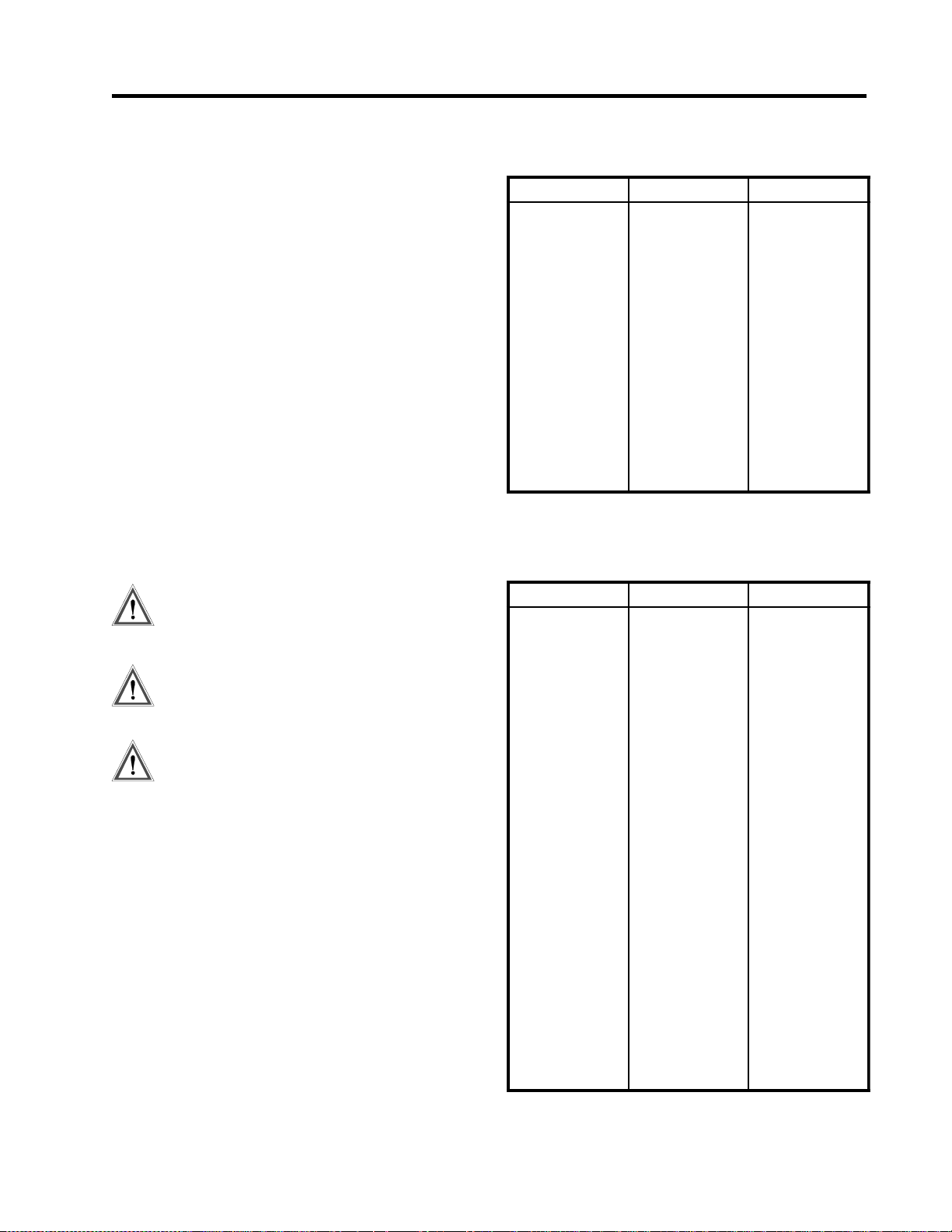
CM2001
Chapter 9
Commissioning
Overview
You can use the procedures in this chapter to verify the
proper operation of the CM2001. Although not a complete functional verification, these tests will check major
operating functions. The scope of testing includes field
testing of the controller inputs/outputs with and without
heat tracing cable. Before commissioning the controller,
read Chapter2 Installation. It provides important information about wiring, mounting and safety concerns. One
should also become familiar with the controller as
described in Chapter 3 Getting Started and Chapter 6
Setpoint values.
Requirements
The test procedures outlined in this chapter verify
functions related to field application. These functions
include RTD inputs, heater output, ground fault, current
and voltage monitoring. To facilitate field testing, it is
recommended functions be turned off or disabled. It is not
mandatory that field testing be done. However, we
recommend procedures in section Placing the Controller
in Service be performed for all installations to verify
proper operation and function of the equipment.
Figure 9.1 Resistance versus Temperature in °C
(DIN 43760 RTD)
C°)smho(RC°)smho(RC°)smho(R
04-72.480898.03100248.571
03-22.880907.43101215.971
02-61.2900105.83102271.381
01-90.6901192.24103228.681
000.00102160.64104264.091
0109.30103128.94105280.491
0297.70104185.35106296.791
0376.11105123.75107203.102
0446.51106140.16108288.402
0593.91107167.46109264.802
0642.32108174.86100330.212
0770.72109161.271
Figure 9.2 Resistance versus Temperature in °F
(DIN 43760 RTD)
Safety Precaution
Dangerously high voltages are present on the
power input and output terminals capable of
causing death or serious injury .
Use extreme caution and follow all safety rules
when handling, testing or adjusting the equipment.
The controller uses components that are sensitive to electro-static discharges. When handling
the unit, care should be taken to avoid contact
with terminal blocks.
Installation Checks:
1. Check that the line voltage to the power inputs does
not exceed the name plate ratings.
2. Check that the current draw of the heat trace cable
does not exceed the name plate ratings.
3. Check that the grounding stud is properly connected
to ground.
RTD Input Test
Equipment:
T wo Resistance Decade Boxes or RTD Simulator
F°)smho(RF°)smho(RF°)smho(R
04-72.4806105.72106392.961
03-74.6807126.92107343.171
02-66.8808147.13108393.371
01-58.0909168.33109334.571
030.3900279.53100484.771
0122.5901280.83101415.971
0293.7902281.04102455.181
0375.9903292.24103485.381
0447.10104283.44104416.581
0509.30105284.64105436.781
0660.60106275.84106456.981
0722.80107266.05107476.191
0883.01108247.25108486.391
0935.21109228.45109496.591
00186.41100309.65100596.791
01138.61101379.851
02179.81102340.161
03101.12103311.361
04142.32104371.561
05173.52105332.761
9.1

CM2001
To test RTD Input,
1. Disconnect the RTD(s) from the control module
ensuring that the leads are adequately labelled.
2. Connect the resistance box as shown in figure 9.3.
3. Choose a test temperature for each RTD input and
select corresponding resistances for each of the
resistance decade boxes using the table of RTD
resistances in figure 9.1 and 9.2. The temperatures
for each RTD should be dif ferent. For the RTD
simulator, set the test temperature of each unit.
4. T urn on power to the controller.
5. Using the R TD definition function
(SETPOINT\HEATER SETUP\RTD DEFINITION),
set to Two RTDS Average.
6. Display the temperature of each RTD
(ACTUAL\OPERA TING VALUES\R TD-A ACTUAL) and (ACTUAL\OPERATING
VALUES\RTD-B ACTUAL). The two values should
agree with the selected temperatures within the
accuracy of the controller and test equipment.
7. If there is a significant discrepancy, consult the
factory for service.
Heater V olt age and Current Test
Equipment:
one voltmeter
one clamp-on ammeter
adjustable load bank (240VAC/10kW)
240VAC/30A single phase variac
Figure 9.3 Test Setup
Chapter 9
You can perform voltage and current measurement tests
on the same test setup. Rather than using an adjustable
load, you can use a fixed load in conjunction with a variac
to adjust the input supply voltage.
T o test heater voltage and current,
1. Disconnect any field wiring to terminals 2,3,4 and 5.
2. Connect the adjustable variac outputs to terminals 2
and 3. Connect the input supply of the variac to either
208 or 240VAC. 120VAC will work but will not
provide an effective test range for voltage testing.
3. Connect the load bank to terminals 4 and 5.
4. Connect the voltmeter across terminals 2 and 3.
5. Connect a clamp-on ammeter around one of the load
cables.
6. Set the variac control for 120VAC and turn on the
power.
7. Force the heater on by setting the manual heater
function for 1 hour (SETPOINT\SETPOINT
TEST\MANUAL HEATER).
8. Display the heater current (ACTUAL\OPERATING
VALUES\HEA TER CURRENT).
9. Adjust the variac control within the voltage range of
the controller and compare the readings of the
display with the ammeter.
10. Display the heater voltage (ACTUAL\OPERA TING
VALUES\HEA TER VOLT AGE).
11. Adjust the variac control to take another set of
readings. Repeat until enough readings are taken to
cover the range. Current and voltage readings should
be within the accuracy of the controller and test
equipment.
12. If there is a significant discrepancy, consult the
factory for service.
Commissioning
9.2

CM2001
Chapter 9
Commissioning
Ground Fault Current T est
Internal GF Test
The controller comes with a ground fault test function that
can be executed from the display
(SETPOINTS\SETPOINT TEST\GF TEST).
T o run this test,
1. Select start now
2. Go to ground fault current (ACTUAL\OPERATING
VALUES\GROUND FAULT CURRENT).
A ground fault current appears for the duration of the test.
If the controller does not see a ground fault current, it will
initiate a GF CT failure alarm indicating the ground fault
monitoring function is not working. The GF test function
only verifies for operation and does not check for measurement accuracy . To check for accuracy , the next test
procedure applies.
External GF Test
Using the same test setup for voltage and current measurement tests, add the following components to the test
setup.
Equipment:
One 240R/250W power resistor (load bank used in
previous procedure may be disconnected and used in
place)
One AC ammeter (0-1A range)
T o test ground fault current,
1. Disconnect the load bank used in the previous test
and reconfigure to 240R if possible.
2. Connect the load bank or power resistor to terminals
2 and 5 of the controller with the ammeter in series.
3. Set the variac control for 120VAC and turn on the
power.
4. Force the heater on by setting the manual heater
function for 1 hour (SETPOINT\SETPOINT
TEST\MANUAL HEATER).
5. Change the GF trip alarm to 1000mA to prevent
nuisance trips during the test. Reset ground fault trip
alarms if necessary.
6. Display ground fault current
(ACTUAL\OPERA TING VALUES\GROUND
F AULT CURRENT).
7. Adjust the variac control to simulate various levels of
ground fault currents through the load and compare
readings from the display with the ammeter. Readings
should be within the accuracy of the controller and
test equipment.
8. If there is a significant discrepancy, consult the
factory for service.
9. Disconnect the load bank after the test.
Alarm Output T est
AC Alarm
Equipment:
one 120VAC/100W Incandescent lamp with socket base
T o test AC alarm contact,
1. Connect one lead of the lamp to terminal 20 of the
controller.
2. Connect 120VAC to open lead of the lamp and
terminal 21.
3. Power on the controller.
4. Ensure all alarms are turned off so that the controller
is in no alarm condition.
5. Set SETPOINTS\SYSTEM SETUP\ALARM
CONFIG to DC:NO AC:NO. Lamp should be off.
6. Force alarm on by setting SETPOINT\SETPOINT
TEST\ALARM TEST to on for 1 hour.
7. Lamp should be on.
DC Alarm
Equipment:
one adjustable DC power supply
one DC incandescent indicator (24VDC or less, 100mA
or less)
T o test DC alarm contact,
1. Connect one lead of the lamp to terminal 22 of the
controller.
2. Connect positive lead of the power supply to the
open lead of the lamp and negative lead to terminal
23.
3. Power on the controller.
4. Set the DC power supply voltage to match the rating
of the bulb.
5. Ensure all alarms are turned off so that the controller
is in no alarm condition.
5. Set SETPOINTS\SYSTEM SETUP\ALARM
CONFIG to DC:NO AC:NO. Lamp should be off.
6. Force alarm on by setting SETPOINT\SETPOINT
TEST\ALARM TEST to on for 1 hour.
7. Lamp should be on.
9.3

CM2001
Chapter 9
Commissioning
Override Input T est
Equipment:
one 120VAC Incandescent lamp
T o test override input,
1. Connect the 120VAC incandescent lamp to terminals
4 and 5.
2. Power on the controller .
3. Make a sure an RTD or simulator is connected to
R TD1A input and set the equipment so that the
control temperature is 100°C.
4. Set RTD definition function (SETPOINT\HEATER
SETUP\RTD DEFINITION) to 1 RTD.
5. Check the heater control temperature located at
ACTUAL\OPERA TING VALUES\CONTROL
TEMP for 100°C.
6. Set the heater setpoint so that it is greater than the
control temperature + deadband at
SETPOINTS\OPERATING VALUES\HEA TER
SETPOINT. The deadband setting is located at
SETPOINT\HEATER SETUP\DEADBAND.
7. The heater should be on. Verify by checking the lamp
is on.
8. Set SETPOINTS\HEATER SETUP\OVERRIDE to
on.
9. The heater should now be off. Verify by checking the
lamp is off.
10. Short override input, terminals 24 and 25 with a short
piece of wire.
11. The heater should be on. Verify by checking the lamp
is on.
Placing the Controller in Service
Programming Setpoints
Before testing the controller with heat trace cable,
program setpoints. Ensure the program enable dip switch
or program access function in the display is set to enabled. It is recommended that you program setpoints in the
operating values group. For users who are not familiar
with the control functions, advanced functions such as
those in the heater setup group should be disabled during
initial startup to simplify troubleshooting.
Initial Startup
After programming setpoints in the operating values
group, the controller is ready for test. Check field connections to make sure they are correctly wired. Power on the
controller and check the control temperature on the
display (ACTUAL\OPERA TING VALUES\CONTROL
TEMP). Verify that the temperature reading is valid.
Assuming the pipe temperature is below the setpoint, the
controller should be calling for heat.
Check heater voltage (ACTUAL\OPERATING
VALUES\HEATER VOL TAGE) on the display to verify
with the line voltage.
Check heater current (ACTUAL\OPERATING
VALUES\HEATER CURRENT) on the display. If the
controller is calling for heat, this value should be greater
than zero; otherwise, a low current alarm or continuity
alarm appears. This is an indication the heater is not
properly wired or functioning correctly . The display value
should correspond to the expected current draw of the
heat trace.
Startup Pr oblems
Breaker Trip Due to Inrush:
If self-regulating heat trace is used, it is possible the
display will show O.L. (overload) because of the in-rush
current exhibit in the heat trace during cold startup. The
heater current range of the controller is up to 60A so that
you can monitor inrush current. The heater current drops
as the pipe temperature warms up. If the circuit breaker
trips during startup, the inrush current is too high for the
breaker rating. Check the heat trace design to make sure
the breaker rating is appropriately sized. Inrush current
can be reduced by enabling the softstart function.
T o reduce inrush current,
1. Power down the controller.
2. Disconnect the heat trace cable from the controller .
3. Power up the controller without the heat trace
4. Set the softstart function to 999 seconds if not turned
on. (SETPOINTS\HEATER SETUP\SOFTSTART).
5. Power down the controller
6. Reconnect the heat trace to the controller .
7. Power up the controller again
8. Check the heater current on the display. The heater
current should be dramatically reduced and gradually
increase as the softstart function allows more current
to flow .
Ground Faults:
Check ground fault current (ACTUAL\OPERATING
VALUES\GROUND F AULT CURRENT) on the display.
Ground fault current should not be over 15mA; otherwise,
ground fault trip or alarm appears on the display . To
troubleshoot ground faults, check heat trace wiring and
moisture in electrical junction boxes and connections.
9.4

CM2001
Chapter 9
Commissioning
Low and High Current Alarms with Self-Regulating
Cable:
Setting values for low and high current alarms with selfregulating cable is more complicated since the heater
output varies with temperature. High current alarms may
occur during startup due to inrush currents and low
current alarms may result when steady-state current is
reached (pipe temperature is near setpoint). You can use
the heat trace curve function that defines the heat trace
power output against the pipe temperature to compensate
the alarm settings and will be discussed later in this
chapter. Otherwise, the high current alarm should be
turned off and low current alarm set below the current
rating of the cable at setpoint temperature.
Low Temperature Alarm:
During startup, a low temperature alarm is expected as
cold fluid in the pipe slowly warms up. As the pipe
temperature increases and exceeds the low temperature
alarm setting, the alarm turns off. Eventually, the pipe
temperature reaches setpoint, at which point the heater
turns off. If the low temperature alarm and heater is on
consistently, it is possible the heat tracing is not supplying
enough heat. Either a higher wattage heat trace or longer
length is required.
High Temperature Alarm:
A high temperature alarm occurs when pipe temperature
exceeds the high temperature alarm setting. This can be
caused by high feed temperature of the fluid. Placement
of the RTD sensor near a hot area or direct exposure to
sunlight may also cause a high temperature alarm. In this
situation, improper pipe heating results. It is recommended that dual RTDs be used in pipes where there is
large fluctuations in temperature.
Powerlimiting
You can use, powerlimiting when the total wattage of the
heat trace cable is not required or to limit inrush current
to the self-regulating cable. The powerlimit function is
located at SETPOINT\HEATER SETUP\POWERLIMIT.
A detail explanation of how this function operates is
described in the Chapter 10 Theory of Operation.
Powerlimiting is set by the desired operating current of
the heat trace. For powerlimit to work properly , the
powerlimit current should be below the nominal current
rating of the heat trace. For example, if the heat trace
draws 20A at its rated voltage and the application only
requires 75% of its rated output, a powerlimit current of
15A will achieve a 75% reduction in power. With the
powerlimit current set, the controller attempts to clamp
the output current at that value.
The minimum powerlimit current setting should be
greater than 10% of the nominal load current. This is
because powerlimiting operates in 10% resolution.
Choosing a powerlimit current below 10% causes the
heater not to turn on since the average heater current at
10% (minimum duty cycle) exceeds the powerlimit
current setting.
Be aware of how current alarms operate with duty cycle
changes. Low current alarm is based on the nominal
current ratings of the heat trace, not the average current.
The low current alarm function converts actual current
readings to the expected current value of the heat trace
operating at 100% duty cycle prior to comparing against
alarm settings. When using powerlimit, the high current
alarm is disabled to prevent false alarms due to
measurement error of the algorithm at low duty cycles.
The error is always positive and therefore does not affect
low current alarms.
Control Scheme
The CM2001 controller supports two types of control
scheme: on/off and proportional. The default is on/off
switching which is used for majority of the applications.
When on/off switching is used, the deadband setting
determines the heater turn off temperature above the
heater setpoint and the heater turn on temperature below
the heater setpoint. The deadband setting is user definable
located at SETPOINTS\HEATER\SETUP\DEADBAND.
In applications requiring tighter control, you can use
proportional control. To enable proportional control,
locate message SETPOINTS\HEATER
SETUP\PROPORTIONAL CONTROL. There is no
proportional gain setting as this is automatically set by the
controller to minimize errors. For further details how the
proportional control function operates, refer to Chapter
10 Theory of Operation.
Heat Trace Curve
Self-regulating heat trace is very difficult to monitor
because the heater current varies with temperature. The
heat trace curve function provides a more effective means
of monitoring this type of heat trace by knowing the
power curve of the heat trace and compensating the alarm
9.5

CM2001
Chapter 9
Commissioning
settings to prevent nuisance alarms. When using the heat
trace curve function, low and high current alarms should
be based on current draw of the heat trace at setpoint
temperature. Locate and select the type of heat trace
located SETPOINT\HEATER SETUP\ HEAT TRACE
CURVE SETUP.
If the heat trace being used is not one of the selections,
obtain the curve parameters from the heat trace manufacturers data sheets. The heat trace curve describes the
power output per foot against pipe temperature and is
defined by a straight line approximation. By drawing the
best straight line through the manufacturer’s curve, you
can calculate the slope and y-intercept by identifying two
points on the straight line. The controller require units of
Watt/ft-°F for slope and Watt/ft for of fset (y-intercept).
From message SETPOINT\HEATER SETUP\ HEA T
TRACE CUR VE SETUP, select user and enter the slope
and offset values for the curve.
RTD
The controller is defaulted to operate with one RTD. If
both RTD inputs are used, you must define the control
scheme. The RTD definition message is located at
SETPOINT\HEATER SETUP\RTD DEFINITION.
Select the control scheme that best suites the application.
If uncertain, choose 2 RTDs averaged or 2 RTDs backup.
Use 2 RTDs lowest in freeze protection or situations
where it is important that the pipe temperature is maintained above setpoint. Use 2-RTDs highest in situations to
prevent overheating. Use RTD B HT cutoff in special
applications where a critical point is measured by RTD B
and turns off the heater when R TD B temperature exceeds
the high temperature alarm.
Read chapter 6 to gain an understanding of all the
functions in order to customize the controller to the
application requirements.
In the event of complete RTD failure, the controller can
force the heater to default on or off. This is defined by
message SETPOINT\HEATER SETUP\ IF RTD FAILS
HEATER GOES. The choice of on or off depends on the
application.
Cost of Power
In order for the energy cost functions to provide correct
information, you should enter the cost per KWh for
electrical power at SETPOINT\SYSTEM SETUP\COST
PER KWh.
Completing the Installation
At this point, the controller has been setup with enough
information to control and monitor the heat trace. Other
functions are less critical and a description on how these
function operate is located in Chapter 6 Setpoint Values.
9.6

CM2001
Nelson Heat Tracing Systems products are supplied with a limited warranty. Complete Terms and Conditions may be found on Nelson's
website at www.nelsonheaters.com.
HEA T TRACING CONTROL
Nelson Heat Tracing Systems P.O. Box 726, Tulsa, Oklahoma, 74101, Tel: (918) 627-5530, Fax: (918) 641-7336
CM2001 02/00 Printed in Canada
 Loading...