

Nelson Installation and Maintenance Manual: GA-2490, CM-3-32 Heat Trace Circuit Management System Manuals & Guides
Page 1

Page 2

CM3-32 Installation and Operations Manual
TABLE OF CONTENTS
I. FEATURES .................................................................................................................. 3
Control & Monitoring ............................................................................................................. 3
II. INSTALLATION .......................................................................................................... 5
Location .................................................................................................................................... 5
Control Power ......................................................................................................................... 5
Ventilation ................................................................................................................................ 5
Conduit Routing ..................................................................................................................... 5
III. OPERATION .............................................................................................................. 8
Channel Select ........................................................................................................................ 8
Channel Display ...................................................................................................................... 8
Individual Channel Enable/Disable .................................................................................... 9
Trip Reset Function ............................................................................................................... 9
Alarm Indication ................................................................................................................... 10
Output Alarm Reset ............................................................................................................. 10
Alarm Log Display ................................................................................................................ 11
Advanced Operations - Maintenance Alerts ................................................................. 12
Maintenance Alert Log ........................................................................................................ 12
Maintenance Alert Status ................................................................................................... 13
IV. START-UP ............................................................................................................... 14
Turning the System On ....................................................................................................... 14
Programming System Parameters ................................................................................... 14
Temperature Units ............................................................................................................... 14
Ground Fault Delay .............................................................................................................. 15
Automatic Test Cycle .......................................................................................................... 16
Programming Individual Channels (Circuits) ............................................................... 16
Sensor Failure Mode ........................................................................................................... 17
Ground Fault Control .......................................................................................................... 18
Global Programming of Channels (Circuits) ................................................................. 19
Advanced Setup Features .................................................................................................. 20
Ambient Control ................................................................................................................... 20
Maintenance Alerts .............................................................................................................. 21
Event Log and Display Settings ....................................................................................... 21
User Login and Passwords ............................................................................................... 23
Changing User Passwords ................................................................................................ 24
Changing Modbus Slave Address (-EC Option) ........................................................... 25
V. TROUBLESHOOTING.............................................................................................. 27
System Operation ................................................................................................................ 27
Section I .................................................................................................................................. 28
Communications Alarm ...................................................................................................... 28
Section II ................................................................................................................................. 29
Temperature Alarm .............................................................................................................. 29
Section III ................................................................................................................................ 30
Load Current Alarm ............................................................................................................. 30
Section IV ............................................................................................................................... 31
Ground Fault Alarm ............................................................................................................. 31
VI. SPECIFICATIONS ................................................................................................... 32
VII. GENERAL COMMUNICATION INFORMATION (-EC OPTION) ............................. 33
VIII. COMMUNICATIONS ............................................................................................. 33
PO Box 726 Tulsa, OK 74101 918-627-5530 Fax 918-641-7336 www.nelsonheaters.com
©2010 Nelson Heat Tracing Systems GA-2490 Rev. 3
August 2012
- 2 -
Page 3

CM3-32 Installation and Operations Manual
I. FEATURES
Control & Monitoring
The CM3-32 Circuit Management System is a microprocessor based control and
monitoring system utilizing standard industrial automation products specifically integrated
for use with electrical heat tracing systems. The system provides temperature and current
monitoring for each heat tracing circuit while communicating additional information to
operations personnel such as temperature alarms, sensor failures, electrical circuit faults,
and overall operational conditions.
The CM3-32 Circuit Management System is mounted in a NEMA 12, 4, or 4X free-standing
industrial enclosure. The system is available in standard configurations up to a maximum
of 32 control circuits per enclosure. The CM3-32 is configured from standard PLC
automation components interfaced with specialized current modules and power handling
devices designed for this specific application. Individual CM3-32 systems can be network
connected through the provided Modbus® RTU communications protocol.
Color Touch Screen Graphics Terminal – 5.7” Color LED analog touch pad, resolution
1024 x 1024, compact flash card memory for user application
Process Temperature Display – actual pipe/vessel temperature is displayed with alarm
indication by animation and color change
Load Current Display – actual heater load current is displayed with alarm indication by
animation and color change
Ground Fault Leakage Display – actual ground fault leakage is displayed with alarm
indication by animation and color change
Heater Status, Condition, and Alarm Displays – real time status of individual channel
control is displayed by alarm banners, animated light bars and/or animated backgrounds
Programmable Setpoint Values – direct programming of the following values is provided:
Maintain Temperature
Deadband
Hi Temperature Alarm
Lo Temperature Alarm
Hi Current Alarm
Lo Current Alarm
Ground Fault Alarms, Alarm and Trip Values
Programmable Operational Features – direct programming of the following features is
provided:
Temperature Units
Ground Fault Delay Option
Automatic Test Cycle Function and Time Intervals
Sensor Failure Mode
Ground Fault Trip Control Function
Ambient Control Function and Channel Identification
Maintenance Alert Function and Settings
System Override Option
PO Box 726 Tulsa, OK 74101 918-627-5530 Fax 918-641-7336 www.nelsonheaters.com
©2010 Nelson Heat Tracing Systems GA-2490 Rev. 3
August 2012
- 3 -
Page 4

CM3-32 Installation and Operations Manual
Global Programming – allows programming of all control setpoint values from a single
input screen
Modbus® Communications – remote monitoring capabilities provided via Modbus® RTU
protocol using simple 2-wire, RS-485 hardware
Web Gate and Web Page Server (ET Suffix Only) – direct control and monitoring is
provided through Ethernet connection to the Graphics Terminal, Web Gate server with
remote terminal diagnostics from the navigator on your PC
Maintenance Alerts – trend analysis of each channel’s electrical characteristics is
provided with actual value indication and alert messaging for use by operations personnel
to focus periodic maintenance efforts more efficiently
PO Box 726 Tulsa, OK 74101 918-627-5530 Fax 918-641-7336 www.nelsonheaters.com
©2010 Nelson Heat Tracing Systems GA-2490 Rev. 3
August 2012
- 4 -
Page 5

CM3-32 Installation and Operations Manual
II. INSTALLATION
Location
The CM3-32 should be located in a suitable location on a flat and level surface. The
enclosure should be bolted to the base and/or wall surface, or adequately supported by
other methods to prevent unsafe installation and/or operational conditions.
NEMA Type 12 (IP55)
Enclosures are intended for indoor use primarily to provide a degree of protection
against dust, falling dirt, and dripping non-corrosive liquids.
NEMA Type 4 (IP66)
Enclosures are intended for indoor or outdoor use primarily to provide a degree
of protection against windblown dust and rain, splashing water, and hose
directed water, undamaged by the formation of ice on the enclosure.
NEMA Type 4X (IP66)
Enclosures are intended for indoor or outdoor use primarily to provide a degree
of protection against corrosion, windblown dust and rain, splashing water, and
hose directed water, undamaged by the formation of ice on the enclosure.
The basic CM3-32 is designed for use in ordinary, non-classified locations. Protecting
electrical equipment in hazardous, classified, locations requires special considerations.
NEMA 4 and 4X Panels supplied with a P Suffix are provided with Type Z Purge equipment
to ensure safe operation within a hazardous location. The protective gas purge supply
must be clean, dry, and free of hydrocarbons or corrosive materials. All protective gas
purge supply pressures must be set correctly and all enclosure doors must be closed
securely. Purged enclosures must not be opened unless power is removed from the
equipment and the area is known to be non-hazardous.
Control Power
The CM3-32 accepts universal voltages of 100-240VAC single phase, 60/50Hz. The panel
is equipped with (2) Form C Alarm Relays that are energized during normal operation.
Should the panel lose control power or activate an alarm, the relays will de-energize
indicating an alarm condition.
Ventilation
The CM3-32 is provided with continuously operating internal circulation fans. These fans
are used for static ventilation and aid heat dissipation from the enclosure by passive
radiation and convection. The accumulation of heat in an enclosure is potentially damaging
to electrical and electronic devices. Overheating can shorten the life expectancy of costly
electrical components or lead to premature failure.
Conduit Routing
When routing conduit to the CM3-32 enclosure, clear space is provided on the top, right
side, and bottom areas. Top entry should be avoided if possible. Top entry provides a
potential moisture path to the electronics and interconnecting wiring. If top entry cannot be
avoided, do not locate conduit entries directly over any exposed electrical equipment. Drip
loops are recommended for all top and/or side entry. A drip loop is a dip or bend in the
wiring to block or shed moisture that may follow a wire to the connection point.
PO Box 726 Tulsa, OK 74101 918-627-5530 Fax 918-641-7336 www.nelsonheaters.com
©2010 Nelson Heat Tracing Systems GA-2490 Rev. 3
August 2012
- 5 -
Page 6
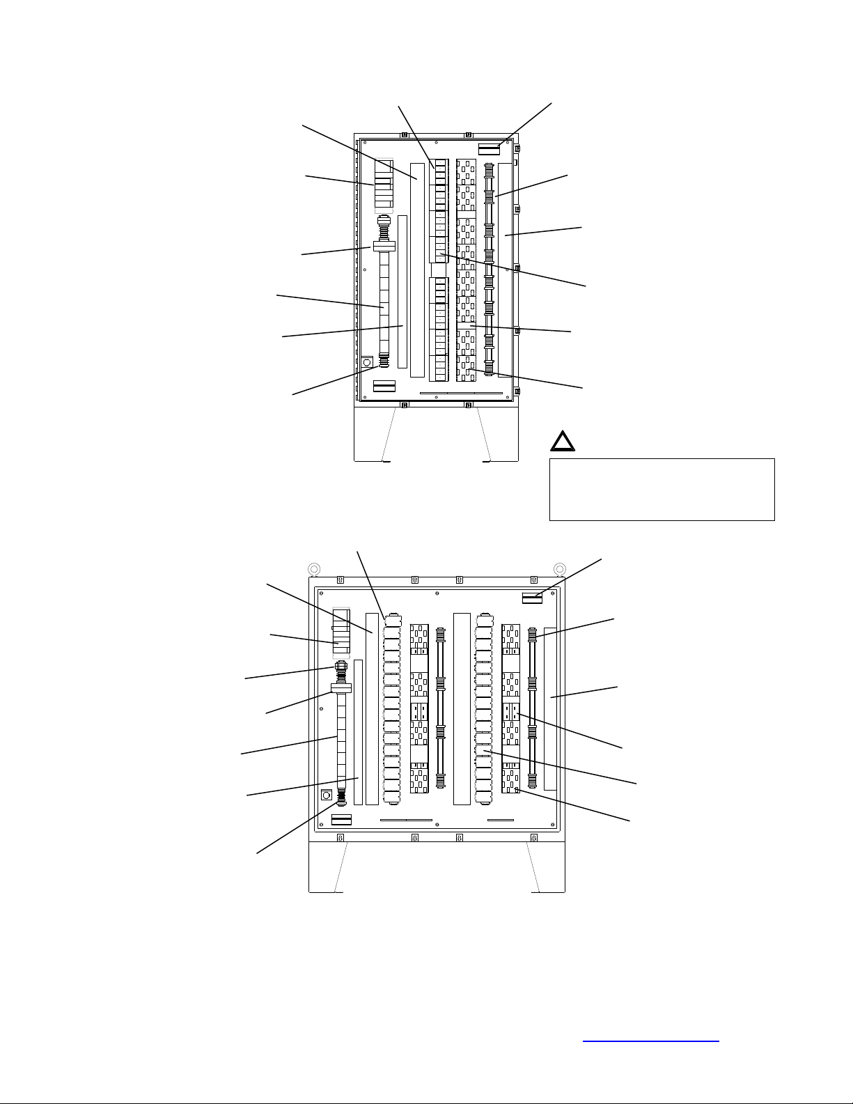
CM3-32 Installation and Operations Manual
WARNING:
Modul
e Assembly
Alarm Relays
Terminal Blocks
Wire Trough
Terminal Blocks
Terminal Blocks
Trough
Module Assembly
Alarm Relays
Terminal Blocks
Wire Trough
Terminal Blocks
Contactors
Moisture intrusion can damage the
modules,
relays
or con
trol wiring.
Processor and I/O
Power Supply
RTD Input
Modules
Sensor Wire
Control Power
Line In
Processor and I/O
Power Supply
RTD Input
Modules
Sensor Wire
Trough
Control Power
Line In
Line In
Terminals
Line In
CM3-32-R2
Figure 1
CM3-32-C
Figure 2
Ventilation Fans
Line Out
Line Out
Wire Trough
Power Relays
(GC-695)
Communications
Interface Modules
CT Modules
(GC0710)
!
CM-3 electronics. Do not place
conduit entry directly over the control
Ventilation Fans
Line Out
Line Out
Wire Trough
Voltage Drivers
(GC0577X01)
CT Modules
(GC0710)
PO Box 726 Tulsa, OK 74101 918-627-5530 Fax 918-641-7336 www.nelsonheaters.com
©2010 Nelson Heat Tracing Systems GA-2490 Rev. 3
August 2012
- 6 -
Page 7

CM3-32 Installation and Operations Manual
Note:
Power Supply
Processor Module
missing or faulty
Discrete I/O Module
(Alarm Relays)
Analog
I/O Module
(RTD Sensors)
Display
RUN LED (green) Processor running
ERR LED (red) Processor or system fault
I/O LED (red) I/O module fault
SER COM LED (yellow) Activity present
CARD ERR LED (red) Memory card
Display
OK LED (green)
24 V LED
(green)
Flash Memory card
RS-485 Internal
communications cable
connection
D25SUB Connector
High Density Connections
to PLC Input Modules
Refer to Assembly and Wiring
Diagrams supplied with panel for
specific connection details
Display
RUN LED (green) Normal
ERR LED (red) On=Internal fault, Flashing=Comm fault
I/O LED (red) On=External fault, Flashing=Terminal
block fault
Channel LED’s (green) On=Normal, Off=Alarm
Display
RUN LED (green) Normal
ERR LED (red) On=Internal fault, Flashing=Comm
fault
I/O LED (red) On=External fault, Flashing=Cable fault
Channel LED’s (green) On=Normal, Flashing=Sensor
failure or no sensor connected
USB cable
connection to
Graphics Display
PLC Module Details
Figure 3
RTD Interface Module
Figure 4
High density cable
connections to RTD
Interface Modules
RTD Interface Module
Part No. 2900774
Instrument Wire for Sensor
Connections (Typical)
PO Box 726 Tulsa, OK 74101 918-627-5530 Fax 918-641-7336 www.nelsonheaters.com
©2010 Nelson Heat Tracing Systems GA-2490 Rev. 3
August 2012
- 7 -
Page 8
CM3-32 Installation and Operations Manual
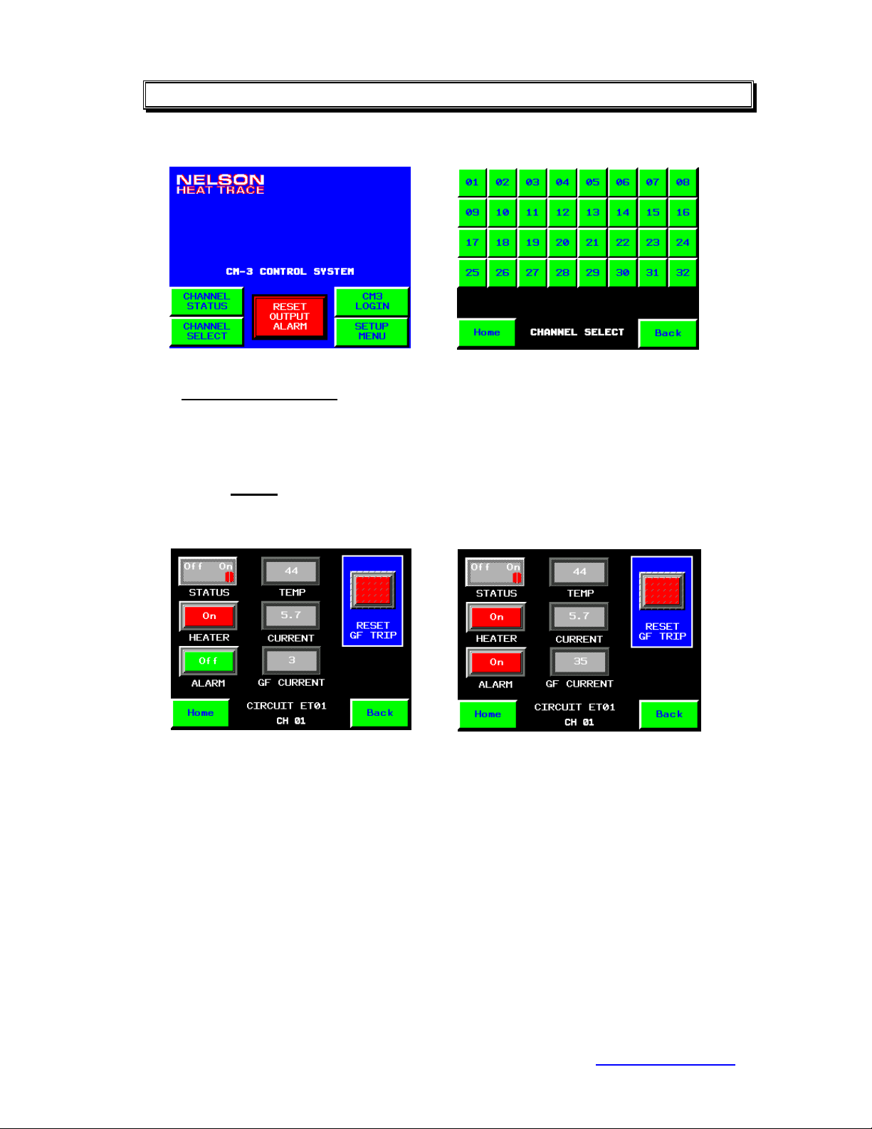
III. OPERATION
Channel Select
To view the current status of each individual control channel, press
< CHANNEL SELECT > found in the lower left corner of the Home page.
This action will access the CHANNEL SELECT page allowing the direct
selection of each individual channel. Press the channel number to access
the specific page required.
Press < Home > on any displayed page to return to the Home page screen.
Channel Display
Individual channel pages display the current status of all operational
conditions. Actual values are compared to programmed values and
indicated by color and/or animation. The actual values are only shown
when the heater is energized. These values will be shown as 0’s during any
de-energized condition.
The status of each heater output control is shown by the switch labeled
STATUS. The HEATER indication bar light will notify the operator as to
whether the heat tracing is currently Off (Green) or On (Red).
When actual conditions are within programmed parameters, the specific
value will be shown in steady-white. If the actual condition is outside of the
programmed parameters, the specific value and ALARM indication bar light
will flash slow off-and-on. If the current condition exceeds the
PO Box 726 Tulsa, OK 74101 918-627-5530 Fax 918-641-7336 www.nelsonheaters.com
©2010 Nelson Heat Tracing Systems GA-2490 Rev. 3
August 2012
- 8 -
Page 9

CM3-32 Installation and Operations Manual
programmed value for Ground Fault Trip, the specific value will change to
flash fast off-and-on.
To view a different channel, press < Back > to access the Channel
Selection page.
Press < Home > on any displayed page to return to the Home page screen.
Individual Channel Enable/Disable
Press < ON > side of the STATUS switch to automatically control the
individual channel by the programmed set point temperature. Press the
< OFF > side of the STATUS switch to disable the displayed channel.
When the STATUS switch is in the < OFF > position, the channel will not be
included during the System Override function or the Auto Test-Cycle
function and all alarms will be disabled.
Press < Home > on any displayed page to return to the Home page screen.
Trip Reset Function
If the Ground Fault Trip function is programmed to be < ON >, a tripped
condition will be indicated by the flashing background around the RESET
GF TRIP button. All ground fault trip conditions must be manually reset.
This operational parameter will disable the heater output device until the
condition is corrected and the reset button is pressed. To reset the tripped
circuit, press < RESET GF TRIP >.
If the Ground Fault Trip function is programmed to < OFF >, the reset switch
will be replaced by the GROUND FAULT TRIP DISABLED indication.
PO Box 726 Tulsa, OK 74101 918-627-5530 Fax 918-641-7336 www.nelsonheaters.com
©2010 Nelson Heat Tracing Systems GA-2490 Rev. 3
August 2012
- 9 -
Page 10

CM3-32 Installation and Operations Manual
Safety Warning:
The system will still reflect ground fault alarm conditions, but the
heater will not be de-energized during any high ground leakage
conditions.
Press < Home > on any displayed page to return to the Home page screen.
Alarm Indication
When an alarm is triggered by the CM-3, a banner will appear at the top of
the Home page and begin scrolling each active alarm condition. This
indication gives the operator the current active alarm(s) and channel
number(s). The Alarm Banner will remain active until the alarm condition is
corrected.
Output Alarm Reset
The CM-3 is equipped with two separate alarm output relays, one is used
for Common Alarm indication and the other is specific to any Ground Fault
conditions only. To clear these alarm outputs, press < RESET OUTPUT
ALARM >. Additional alarm conditions will activate these alarm outputs
accordingly. These alarm contacts are designed to be used for external
indication of alarm status.
PO Box 726 Tulsa, OK 74101 918-627-5530 Fax 918-641-7336 www.nelsonheaters.com
©2010 Nelson Heat Tracing Systems GA-2490 Rev. 3
August 2012
- 10 -
Page 11

CM3-32 Installation and Operations Manual
Alarm Log Display
To view all current alarms, press < CHANNEL STATUS > in the lower left
corner of the page. This will display the Channel Summary page. Any
channels that are currently in alarm will be represented by the Alarm Banner
on the lower portion of the page and the specific channel number will be
flashing off-and-on. Acknowledge specific Channel Alarms by pressing
the appropriate channel number. Press < Alarm Log > to directly access
the stored list of alarms.
This page will show all current alarms and their status. Alarm messages
shown in Red are active, those shown in Green have returned to normal.
All alarms are stamped with the Date and Time. You can directly select a
specific alarm message by pressing the block directly to the left of the
message as shown by the black and white arrow above.
These icons move the cursor up or down one row. Cursor Up moves the
cursor up one row. Cursor Down moves the cursor down one row.
These icons scroll one page up or down. Page Up and Page Down are
useful when there are too many alarms to fit on a single page of the alarm
summary. Page Up moves the display up one page. Page Down moves
the display down one page.
PO Box 726 Tulsa, OK 74101 918-627-5530 Fax 918-641-7336 www.nelsonheaters.com
©2010 Nelson Heat Tracing Systems GA-2490 Rev. 3
August 2012
- 11 -
Page 12

CM3-32 Installation and Operations Manual
The Clear and Clear All icons remove all instances of an alarm from the
alarm summary. The variable remains in the alarm state, but the associated
alarm message will not appear anymore in the alarm summary display.
Return to normal alarms cannot be cleared with these operations.
The purpose of this operation is to remove an alarm message that displays
erroneously. This could be the result of equipment failure such as a faulty
sensor, or of a single alarm generating multiple alarm messages.
The Delete and Delete All icons delete alarms from the current alarm list.
Advanced Operations - Maintenance Alerts
If the Maintenance Alert function is activated during system set-up,
additional features allowing access to the Alert Log and Alert Status pages
are visible to the operator.
Maintenance Alert Log
This page will show all maintenance alerts and their status. Alert messages
shown in Red are active, those shown in Green have been reset in the Alert
Status page for each individual channel. All alerts are stamped with the
Date and Time. You can delete all alerts or individual alerts from this page.
You may scroll up/down or right/left using the displayed scroll bars.
PO Box 726 Tulsa, OK 74101 918-627-5530 Fax 918-641-7336 www.nelsonheaters.com
©2010 Nelson Heat Tracing Systems GA-2490 Rev. 3
August 2012
- 12 -
Page 13

CM3-32 Installation and Operations Manual
Maintenance Alert Status
To view active alert statistics, press < Alert Status > on the Channel
Display page. This page will provide the operator with the highest value
that the temperature sensor has recorded and the initial values for load
current and ground fault leakage.
If the actual value exceeds the calculated values programmed during the
set-up operations, the current actual values will be displayed on the CH
STATISTICS page and a message will be added to the Alert Log.
An individual message on the Alert Log can be acknowledged by pressing
< RESET ALERTS > on the STATISTICS page for that channel. Alert
messages shown in Red are active, those shown in Green have returned to
normal.
Once maintenance or replacement has been completed on these circuits,
press < RESET VALUES > to replace the initial values used in the
maintenance alert calculations with current actuals.
For a detailed description of the operational icons, refer to the Alarm Log
Display section.
PO Box 726 Tulsa, OK 74101 918-627-5530 Fax 918-641-7336 www.nelsonheaters.com
©2010 Nelson Heat Tracing Systems GA-2490 Rev. 3
August 2012
- 13 -
Page 14

CM3-32 Installation and Operations Manual
IV. START-UP
Turning the System On
Using the branch breaker providing control power to the internal power
supplies, energize the CM-3 system and allow the unit to complete its selfcheck sequence and display the Home page. On initial start-up, the unit
may require programming of the System Parameters and the Channel
Parameters for the specific application. To access the CONTROLLER
SET-UP page, press < SETUP MENU >. From this page you can access
the all application pages required to completely program the CM-3.
The SYSTEM OVERRIDE switch is also located on the CONTROLLER
SET-UP page. By selecting the < ON > position, all channels that are
currently enabled will be forced ON regardless of process conditions. For
safety reasons, this switch will not override any circuits that are tripped out
due to high ground fault conditions.
Programming System Parameters
To access the System Set-Up Parameters, press < System Setup > from
the CONTROLLER SET-UP page. Access to this page requires the PROG
user name and password.
Temperature Units
To select the CM-3 operation to either Fahrenheit or Celsius, press
< F > or < C > on the UNITS switch. This selection converts the actual
PO Box 726 Tulsa, OK 74101 918-627-5530 Fax 918-641-7336 www.nelsonheaters.com
©2010 Nelson Heat Tracing Systems GA-2490 Rev. 3
August 2012
- 14 -
Page 15

CM3-32 Installation and Operations Manual
sensor readings and compares its value to the programmed setpoint values.
Programmed Setpoint Values:
Setpoint
Deadband
Hi Temp
Lo Temp
All setpoint values must be input in the correct unit selected, the CM-3
does not automatically convert values between units.
Ground Fault Delay
The CM-3 is equipped with a ground fault delay feature that will delay the
alarm and trip functions during unidentified transient conditions.
During normal operation, the CM-3 will trip (de-energize) the heat tracing
circuit immediately when a high ground fault condition is observed.
In some situations, unidentified transient conditions can lead to nuisance
tripping of heater circuits that require manual resetting to maintain plant
operations. Some examples of this might be; high dew point conditions
during shut down, high amperage circuit wiring in close proximity to heater
circuits, motors/compressors wiring in close proximity to heater circuits, high
gain antennas, etc. In those situations, the ground fault delay may be used.
By turning the GROUND FAULT DELAY switch to < ON >, a 10 second
delay is provided to allow those transient conditions to pass without causing
false alarms or tripping of the heat tracing circuits.
Safety Warning:
It is recommended that any abnormal ground fault leakage conditions
be thoroughly investigated before activating this feature.
PO Box 726 Tulsa, OK 74101 918-627-5530 Fax 918-641-7336 www.nelsonheaters.com
©2010 Nelson Heat Tracing Systems GA-2490 Rev. 3
August 2012
- 15 -
Page 16

CM3-32 Installation and Operations Manual
Automatic Test Cycle
The CM-3 can be programmed to perform an Auto Test-Cycle function for
periodic maintenance for seasonal heating applications. This feature will
energize all enabled channels at programmed intervals and report any
alarm conditions that may have developed during the system idle period.
To activate this feature, press the < ON > side of the AUTO-TEST CYCLE
switch. Next, select the HOUR INTERVALS to determine the length of time
between test cycles. The CM-3 can be programmed up to 720 hours (30
days) between cycles. The minimum and maximum values are displayed
with each input selection. To change the cycle time, press the display field
and enter the new value. Press < Enter > to input this value in to the
operational program.
To continue programming the CM-3, press < Back > to return to the
Controller Setup page.
Press < Home > on any displayed page to return to the Home page screen.
Programming Individual Channels (Circuits)
To program individual control channels, press < SETUP MENU > found in
the lower right corner of the Home page screen. This action will access the
CONTROLLER SET-UP page. Press < Channel Setup > to access the
CHANNEL SET-UP page allowing the direct selection of each individual
channel. Access to this page requires a MAINT user name and password.
Press the < CH > number to access the specific channel page required.
PO Box 726 Tulsa, OK 74101 918-627-5530 Fax 918-641-7336 www.nelsonheaters.com
©2010 Nelson Heat Tracing Systems GA-2490 Rev. 3
August 2012
- 16 -
Page 17

CM3-32 Installation and Operations Manual
Program any setpoint value by pressing the display field for the value to be
changed. A Data Entry screen will be displayed. The minimum and
maximum values are displayed with each input selection. Enter the new
value from the keyboard. Press < Enter > when finished.
Setpoint: value range = -328 to +1392
Deadband: value range = 1 to 10
Hi-Temp: value range = -328 to +1392
Lo-Temp: value range = -328 to +1392
Description: value range = 15 Characters
Sensor Failure Mode
When a shorted or open sensor is detected, you can select the heater
output to energize or de-energize under failure conditions. Press the
< ON > side of the Sensor Failure Mode switch if you want the heater to be
energized, press the < OFF > side of the switch if you want the heater to be
de-energized. When the sensor is operational, the CM-3 will return to
normal operation automatically.
Press < Page 2 > to access additional setpoint and control options.
PO Box 726 Tulsa, OK 74101 918-627-5530 Fax 918-641-7336 www.nelsonheaters.com
©2010 Nelson Heat Tracing Systems GA-2490 Rev. 3
August 2012
- 17 -
Page 18

CM3-32 Installation and Operations Manual
Program any setpoint value by pressing the display field for the value to be
changed. A Data Entry screen will be displayed. The minimum and
maximum values are displayed with each input selection. Enter the new
value from the keyboard. Press < Enter > when finished.
High Current: value range = 0 to 30 amps
Low Current: value range = 0 to 30 amps
GF Alarm: value range = 0 to 900 milliamps
GF Trip: value range = 0 to 900 milliamps
To enter a value less than 1, a zero must be entered before the decimal
point. Example: 0.2, 30.0, etc.
Ground Fault Control
The Ground Fault Trip feature is used in applications where, for either
process or safety reasons, the facility has elected to allow the heater to
remain energized under fault conditions. The CM-3 is programmed with all
channels defaulted with the GF Control switch in the < ON > position. The
GF Trip display field is hidden when the GF Control switch in the < OFF >
position.
The specific requirements for this operational feature can be found in
the National Electric Code, Article 427, and Equipment Protection.
Safety Warning:
By programming the GF Control switch to the < OFF > position, the specific channel will alarm
and show an indication that the ground leakage has exceeded the programmed trip value but
the heater will remain energized.
PO Box 726 Tulsa, OK 74101 918-627-5530 Fax 918-641-7336 www.nelsonheaters.com
©2010 Nelson Heat Tracing Systems GA-2490 Rev. 3
August 2012
- 18 -
Page 19

CM3-32 Installation and Operations Manual
Global Programming of Channels (Circuits)
To access the CONTROLLER SET-UP page, press < SETUP MENU > on
the Home page. To access the Global Program Setup Parameters, press
< Global Setup >. Access to this page requires a MAINT user name and
password.
Program any setpoint value by pressing the display field for the value to be
changed. A Data Entry screen will be displayed. The minimum and
maximum values are displayed with each input selection. Enter the new
value from the keyboard. Press < Enter > when finished.
Set point: value range = -328 to +1392
Dead band: value range = 1 to 10
Hi-Temp: value range = -328 to +1392
Lo-Temp: value range = -328 to +1392
High Current: value range = 0 to 30 amps
Low Current: value range = 0 to 30 amps
GF Alarm: value range = 0 to 500 milliamps
GF Trip: value range = 0 to 500 milliamps
To enter a value less than 1, a zero must be entered before the decimal
point. Example: 0.2
The Sensor Failure Mode and Ground Fault Trip feature cannot be
programmed globally. These features have safety related concerns and the
programming conditions should be viewed on an individual basis.
PO Box 726 Tulsa, OK 74101 918-627-5530 Fax 918-641-7336 www.nelsonheaters.com
©2010 Nelson Heat Tracing Systems GA-2490 Rev. 3
August 2012
- 19 -
Page 20

CM3-32 Installation and Operations Manual
When all displayed values have been programmed, enter all values by
pressing < ENTER > Values.
Press < Home > on any displayed page to return to the Home page screen.
Advanced Setup Features
To access the Controller Set-Up page, press < SETUP MENU > on the
Home page. To access the Advanced Setup features, press
< Advanced Setup >. Access to this page requires a MAINT user name
and password.
Ambient Control
The Ambient Control feature on the CM-3 allows the system to be
configured for single sensor input. To activate this feature, press the
< ON > side of the AMBIENT CONTROL switch. Next, select the number of
circuits to be connected and controlled by the single sensor input. Program
the value by pressing the display field for the value to be changed. A Data
Entry screen will be displayed. Enter the new value from the keyboard.
Press < Enter > when finished.
The CM-3 can be programmed for any number combination of process and
ambient controlled circuits. All Ambient Controlled circuits will operate
utilizing the temperature sensor connected to RTD Input #1.
In the input example shown above, Channels 1-8 will use the temperature
sensor connected to RTD Input #1 and the remaining channels will operate
from their individually connected sensors
PO Box 726 Tulsa, OK 74101 918-627-5530 Fax 918-641-7336 www.nelsonheaters.com
©2010 Nelson Heat Tracing Systems GA-2490 Rev. 3
August 2012
- 20 -
Page 21

CM3-32 Installation and Operations Manual
Maintenance Alerts
The Maintenance Alerts feature on the CM-3 provides operations personnel
with an additional tool for scheduling system maintenance. Like similar
features found on process control systems, this option monitors each
heating cable and looks for trends that relate to future maintenance
requirements. This feature is designed to detect possible maintenance
situation before programmed alarm thresholds are exceeded.
When active, the CM-3 monitors the actual load current and ground fault
leakage of each individual circuit and compares them to their initial values.
If a value is outside of the programmed parameters, it records the specific
value and triggers a Maintenance Alert message for use by operational
personnel.
To activate this feature, press the < ON > side of the MAINT ALERTS
switch. Next, input the percentage of initial load current that will trigger a Lo
Current maintenance alert. Program the value by pressing the display field
for the value to be changed. A Data Entry screen will be displayed. Enter
the new value from the keyboard. Press < Enter > when finished.
Each time the heater is cycled, the current and ground fault values are
stored. The load current value is compared to the programmed percentage
value to determine if any preventive action should be taken. The ground
fault value is compared to previous readings looking for increasing levels of
leakage that may result in future safety concerns.
Event Log and Display Settings
PO Box 726 Tulsa, OK 74101 918-627-5530 Fax 918-641-7336 www.nelsonheaters.com
©2010 Nelson Heat Tracing Systems GA-2490 Rev. 3
August 2012
- 21 -
Page 22

CM3-32 Installation and Operations Manual
To access the CONTROLLER SET-UP page, press < SETUP MENU > on
the Home page.
Event Log
To access the Event Log Summary, press
< Event Log >. The Event Log provides detailed system level information
regarding the operation of the graphics terminal. This can be used to
troubleshoot any problems related to normal communications with the PLC
processor.
Display Settings
To access the Display Settings features, press
< Display Settings >.
From the System page, you can modify several parameters within the
graphic display module.
Date and Time
To set the Date and Time, press the display field for the value to be
changed. A Data Entry screen will be displayed. Enter the new value from
the keyboard. Press < Enter > when finished.
Restart
You may elect to Restart the Graphics Display Unit in the event the unit
loses its connection to the PLC or an updated program has been provided in
the form of a compact flash card.
Brightness
You may elect to change the brightness and contrast on the display to better
suit the installed light conditions.
If all modified parameter on this page have been completed, you can press
< To Run Mode > and return to the operating program or press < Offline >
to access additional parameters.
PO Box 726 Tulsa, OK 74101 918-627-5530 Fax 918-641-7336 www.nelsonheaters.com
©2010 Nelson Heat Tracing Systems GA-2490 Rev. 3
August 2012
- 22 -
Page 23

CM3-32 Installation and Operations Manual
From the Offline page, you can modify additional parameters within the
graphic display module.
Network and Web Gate – ET Version Only
To set the Network IP Address, press the display field for the value to be
changed. A Data Entry screen will be displayed. Enter the new value from
the keyboard. Press < Enter > when finished. You may also change the
Security Settings for network access on this page.
Backlight
The Backlight settings allow the user to set the duration of time allowed
before the display activates a screen saver mode. The unit can also be set
for continuous use. This setting will reduce the operational life of the light
source.
User Login and Passwords
PO Box 726 Tulsa, OK 74101 918-627-5530 Fax 918-641-7336 www.nelsonheaters.com
©2010 Nelson Heat Tracing Systems GA-2490 Rev. 3
August 2012
- 23 -
Page 24

CM3-32 Installation and Operations Manual
To enter the user name and password, access the User Login screen by
pressing < CM3 LOGIN > in the lower right hand corner of the screen. The
Login page allows the user to enter a user name and password allowing
access the desired programming pages. The MAINT user name and
password allows the operator to access all Channel and Global
programming pages. The PROG user name and password allows the
operator to access all system programming pages.
Input the User Name and Password by pressing the appropriate display
field. A Data Entry screen will be displayed. Enter the new value from the
keyboard. Press < Enter > when finished.
Once both the User Name and Password have been input, you must press
the < Lock > icon to complete the login process. A successful login will
show the input name in the Current User field. Press < Home > icon to
return to the Home page screen.
The CM-3 will automatically return to a secure condition after 15 minutes of
inactivity. To logout immediately, press < LOGOUT > on the Home page
screen.
Changing User Passwords
The default passwords in the CM3 may be changed when the login process
has been completed by the PROG level user. The < CHANGE
PASSWORD > icon will become visible on the HOME page.
PO Box 726 Tulsa, OK 74101 918-627-5530 Fax 918-641-7336 www.nelsonheaters.com
©2010 Nelson Heat Tracing Systems GA-2490 Rev. 3
August 2012
- 24 -
Page 25

CM3-32 Installation and Operations Manual
To change a password, first select the appropriate Group. SecurityGroup01
= MAINT level access and SecurityGroup02 = PROG level access. Insert
the new password by pressing the appropriate display field. A Data Entry
screen will be displayed. Enter the new password from the keyboard and
press < Enter > when finished.
Once the new Password has been entered and confirmed, press the
< Exchange > icon to complete the process. Press the < Exit > icon to
return to the previous programming page.
Changing Modbus Slave Address (-EC Option)
The Modbus Slave Address in the CM3 may be changed when the login
process has been completed by the PROG level user. The < MODBUS
ADDRESS > icon will become visible on the HOME page.
PO Box 726 Tulsa, OK 74101 918-627-5530 Fax 918-641-7336 www.nelsonheaters.com
©2010 Nelson Heat Tracing Systems GA-2490 Rev. 3
August 2012
- 25 -
Page 26

CM3-32 Installation and Operations Manual
Input the new Modbus slave address by pressing the appropriate display
field. A Data Entry screen will be displayed. Enter the new value from the
keyboard. Press < Enter > when finished.
When a new value is entered, the status indication bar light will change to
Red.
When all displayed value has been programmed, enter the new address by
pressing the < ENTER > button. If the address change is successful, the
status indication bar light will turn to Green to indicate the new address is
now active in the control system.
Press < Home > on any displayed page to return to the Home page screen.
PO Box 726 Tulsa, OK 74101 918-627-5530 Fax 918-641-7336 www.nelsonheaters.com
©2010 Nelson Heat Tracing Systems GA-2490 Rev. 3
August 2012
- 26 -
Page 27

CM3-32 Installation and Operations Manual
V. TROUBLESHOOTING
System Operation
S
PO Box 726 Tulsa, OK 74101 918-627-5530 Fax 918-641-7336 www.nelsonheaters.com
©2010 Nelson Heat Tracing Systems GA-2490 Rev. 3
August 2012
- 27 -
Page 28

CM3-32 Installation and Operations Manual
Section I
Communications Alarm
PO Box 726 Tulsa, OK 74101 918-627-5530 Fax 918-641-7336 www.nelsonheaters.com
©2010 Nelson Heat Tracing Systems GA-2490 Rev. 3
August 2012
- 28 -
Page 29

CM3-32 Installation and Operations Manual
Section II
Temperature Alarm
PO Box 726 Tulsa, OK 74101 918-627-5530 Fax 918-641-7336 www.nelsonheaters.com
©2010 Nelson Heat Tracing Systems GA-2490 Rev. 3
August 2012
- 29 -
Page 30

CM3-32 Installation and Operations Manual
Section III
Load Current Alarm
PO Box 726 Tulsa, OK 74101 918-627-5530 Fax 918-641-7336 www.nelsonheaters.com
©2010 Nelson Heat Tracing Systems GA-2490 Rev. 3
August 2012
- 30 -
Page 31

CM3-32 Installation and Operations Manual
Section IV
Ground Fault Alarm
PO Box 726 Tulsa, OK 74101 918-627-5530 Fax 918-641-7336 www.nelsonheaters.com
©2010 Nelson Heat Tracing Systems GA-2490 Rev. 3
August 2012
- 31 -
Page 32

CM3-32 Installation and Operations Manual
VI. SPECIFICATIONS
Supply Voltage (1-Phase)
Power Input
R2 Version
R2 Version (CWP)
C Version
C Version (CWP)
Operating Environment
Operational (Standard)
Operational (with Cold Weather
Package)
Storage
Relative Humidity
Sensor Input
Temperature Range
Accuracy
Power Handling
R2 Version
C Version
Load Current Range
Accuracy
Ground Fault Leakage Range
Accuracy
Display
Operator Interface
Programming Options
Auto-Test Cycle Frequency
Sensor Failure Output
Control Mode
Channel Enable/Disable
Hi Temp Alarm
Lo Temp Alarm
Hi Current Alarm
Lo Current Alarm
Ground Fault Alarm
Ground Fault Trip Level
Ground Fault Trip Enable/Disable
Sensor Failure Alarm
Alarm Output Type
Alarm Output
Communications (-EC Option)
Communications Options
Universal Input, 85 to 264VAC, 50-60Hz
220 Watts Nominal
645 Watts Nominal
290 Watts Nominal
855 Watts Nominal
-15 to +40ºC
-40 to +40ºC
-40 to +85ºC
0-95% Non-condensing
RTD, 100, Platinum, 3-Wire
-328 to +1392ºF (-200 to +756ºC)
1% of Range
100 to 277VAC, Relays
100 to 600VAC, Contactors
0.1 to 24.0 Amps
±10%
1-900 milliamps
±10%
Color LED, CFL 75,000 h
Analog Touch Pad, Resolution 1,024 x 1,024
Individual Channel, Global
1 to 720 Hours
On/Off, Selectable per Channel
On/Off with Adjustable Deadband
Yes, Selectable per Channel
Adjustable over Temperature Range
Adjustable over Temperature Range
Adjustable, 0.0 to 30.0A
Adjustable, 0.0 to 30.0A
Adjustable, 0 to 500mA
Adjustable, 0 to 500mA
Yes, Selectable per Channel
Yes, Open and Shorted
Common and Separate Ground Fault
Form C, 7.0A @ 120/240VAC
Modbus® RTU, Slave Mode Only, Non-Isolated
RS-485, 2-Wire Operation
Consult Factory
PO Box 726 Tulsa, OK 74101 918-627-5530 Fax 918-641-7336 www.nelsonheaters.com
©2010 Nelson Heat Tracing Systems GA-2490 Rev. 3
August 2012
- 32 -
Page 33

CM3-32 Installation and Operations Manual
VII. GENERAL COMMUNICATION INFORMATION (-EC OPTION)
Serial Port:
Baud Rate:
Data Bits:
Stop Bits:
Parity:
Device Address:
Select the serial port that corresponds to your RS-485 Adapter.
USB to Serial adapters may be used for devices without serial connections.
9600
8
1
Even
User Defined
VIII. COMMUNICATIONS
The Nelson Heat Trace CM332-EC supports a subset of the Modbus® RTU protocol format that provides
monitoring, programming, and control functions using Read (3) and Write (6) register commands. The
actual address for each register is a combination of 3 elements; Data Type, Specific Address and the
Channel Number. Example: The Actual Temperature for Channel 12 would be located at address
%MW1712.
DATA TYPE, %M = Discrete Variable, %MW = Integer Variables
VARIABLE NAME MODBUS ADDRESS DESCRIPTION / VALUE RANGE
Alarm WORD %MW 1 XX
,0 Enable Channel
,1 Common Alarm
,2 Not Used
,3 Sensor Failure Alarm
,4 High Temperature Alarm
,5 Low Temperature Alarm
,6 High Current Alarm
,7 Low Current Alarm
,8 Ground Fault Alarm
,9 Ground Fault Trip
,10 Not Used
,11 Not Used
,12 Not Used
,13 Statistics Enable
,14 Low Amperage Alert
,15 High Ground Fault Current Alert
Alarm Acknowledge %M 1 XX = momentary ON to reset
Ambient Control OFF %M 4 = momentary ON to reset
Ambient Control ON %M 5 = 0 if OFF, = 1 if ON
Ambient Controlled Circuit Count %MW 1 0 to 32 ( = number of circuits)
Amperage Percent Value %MW 2 0 to 100 ( = percent)
Auto Test Active %M 6 = 0 if OFF, = 1 if ON
Auto Test Cycle OFF 7 = momentary ON to reset
Auto Test Cycle ON %M 8 = 0 if disabled, = 1 if enabled
Auto Test Frequency in Hours %MW 3 1 to 720 ( = x if set to x Hours)
SPECIFIC ADDRESS
CHANNEL NUMBER, XX = 01 thru 32
WORD to BIT, if applicable
PO Box 726 Tulsa, OK 74101 918-627-5530 Fax 918-641-7336 www.nelsonheaters.com
©2010 Nelson Heat Tracing Systems GA-2490 Rev. 3
August 2012
- 33 -
Page 34

CM3-32 Installation and Operations Manual
VARIABLE NAME MODBUS ADDRESS DESCRIPTION / VALUE RANGE
Communications Error CT Module
Communications Error CT Module
Communications Error CT Module
Communications Error CT Module
Communications Error CT Module
Communications Error CT Module
Communications Error CT Module
Communications Error CT Module
Communications Error Interface
Communications Error Interface
Ground Fault Alarm Setpoint
Ground Fault Current (Actual) %MW 5 XX
Ground Fault Trip Control OFF %M 10 XX
Ground Fault Trip Control ON %M 9 = momentary ON to reset
Ground Fault Trip Reset %M 11 XX = momentary ON to reset
Ground Fault Trip Setpoint
High Current Alarm Setpoint
High Ground Fault Level Alert %M 14 XX = 0 if OFF, = 1 if ON
High Ground Fault Level
High Temperature Alarm %M 16 XX = 0 if OFF, = 1 if ON
High Temperature Alarm Setpoint
Initial Ground Fault Current
Low Amperage Level Alert %M 17 XX = 0 if OFF, = 1 if ON
Low Current Alarm Setpoint
Low Temperature Alarm %M 19 XX = 0 if OFF, = 1 if ON
Common Alarm %M 3 XX = 0 if disabled, = 1 if enabled
GF1
GF2
GF3
GF4
GF5
GF6
GF7
GF8
Module RI1
Module RI2
Deadband
Disable Channel %M 4 XX = momentary ON to reset
Enable Channel
Exposure Temperature %MW 3 XX
Force Channel %M 6 XX = 0 if disabled, = 1 if enabled
Ground Fault Alarm
Ground Fault Delay %M 21
Ground Fault Trip %M 8 XX = 0 if OFF, = 1 if ON
Heater ON %M 12 XX = 0 if OFF, = 1 if ON
High Current Alarm
Initial Amperage
Low Amperage Level
Low Current Alarm
%M 11 = 0 if disabled, = 1 if enabled
%M 12 = 0 if disabled, = 1 if enabled
%M 13 = 0 if disabled, = 1 if enabled
%M 14 = 0 if disabled, = 1 if enabled
%M 16 = 0 if disabled, = 1 if enabled
%M 17 = 0 if disabled, = 1 if enabled
%M 18 = 0 if disabled, = 1 if enabled
%M 19 = 0 if disabled, = 1 if enabled
%M 10 = 0 if disabled, = 1 if enabled
%M 15 = 0 if disabled, = 1 if enabled
%MW 2 XX
%M 5 XX
%M 7 XX
%MW 4 XX
%MW 6 XX
%M 13 XX
%MW 7 XX
%MW 8 XX
%MW 9 XX
%MW 10 XX 1 to 500 ( = x if set to x/10 Amps)
%MW 11 XX
%MW 12 XX
%M 18 XX
%MW 13 XX
10 to 100 ( = x if set to x/10 Degrees)
For 2 degree, actual value = 20
= 0 if disabled, = 1 if enabled
( = x if reading x/10 Degrees)
For 125 degrees, actual value = 1250
= 0 if OFF, = 1 if ON
1 to 900 ( = x if set to x mA)
For 30mA, actual value = 30
( = x if reading x/10 mA)
For 10mA, actual value = 100
= 0 if OFF, = 1 if ON
= 0 if enabled, = 1 if disabled
1 to 900 ( = x if set to x mA)
For 50mA, actual value = 50
= 0 if OFF, = 1 if ON
1 to 500 ( = x if set to x/10 Amps)
For 30.0 amps, actual value = 300
1 to 900 ( = x if set to x mA)
For 30mA, actual value = 30
-3280 to 13820 ( = x if set to x/10 Degrees)
For 125 degrees, actual value = 1250
For 2.5 amps, actual value = 25
1 to 900 ( = x if set to x mA)
For 30mA, actual value = 30
1 to 500 ( = x if set to x/10 Amps)
For 2.5 amps, actual value = 25
= 0 if OFF, = 1 if ON
1 to 500 ( = x if set to x/10 Amps)
For 2.5 amps, actual value = 250
PO Box 726 Tulsa, OK 74101 918-627-5530 Fax 918-641-7336 www.nelsonheaters.com
©2010 Nelson Heat Tracing Systems GA-2490 Rev. 3
August 2012
- 34 -
Page 35

CM3-32 Installation and Operations Manual
VARIABLE NAME MODBUS ADDRESS DESCRIPTION / VALUE RANGE
Low Temperature Alarm Setpoint
Load Current (Actual) %MW 15 XX
Override OFF
Override ON %M 24 = 0 if OFF, = 1 if ON
Reset Channel Alerts
Reset Initial Values %M 23 XX = momentary ON to reset
Reset Output Alarm Relays
Sensor Failure Mode OFF %M 25 XX = momentary ON to reset
Sensor Failure Mode ON
Sensor Failure Alarm %M 20 XX = 0 if OFF, = 1 if ON
Setpoint
Statistics Disable %M 27 = momentary ON to reset
Statistics Enable %M 28 = 0 if OFF, = 1 if ON
System Alarm WORD %MW 10
System Information WORD %MW 11
Temperature (Actual) %MW 17 XX
Units Celsius OFF
Units Celsius ON %M 30 = 0 if OFF, = 1 if ON
%MW 14 XX
%M 23
%M 21 XX
%M 25
%M 24 XX
%MW 16 XX
,0 Auto Test Active
,1 Not Used
,2 Communications Error CT Module GF1
,3 Communications Error CT Module GF2
,4 Communications Error CT Module GF3
,5 Communications Error CT Module GF4
,6 Communications Error CT Module GF5
,7
,8 Communications Error CT Module GF7
,9
,10 Not Used
,11 Communications Error Interface Module RI1
,12 Communications Error Interface Module RI2
,13 Not Used
,14 Override All ON
,15 Not Used
,0 Activate 16 Channels
,1 Activate 24 Channels
,2 Activate 32 Channels
,3 Not Used
,4 Ambient Control Enabled
,5 Auto Test Enabled
,6 Ground Fault Delay Enabled
,7 Statistics Enabled
,8 Units Enabled for Celsius
,9 Not Used
,10 Override All ON
,11 Not Used
,12 Not Used
,13 Not Used
,14 Not Used
,15 Not Used
%M 29
-3280 to 13820 ( = x if set to x/10 Degrees)
-3280 to 13820 ( = x if set to x/10 Degrees)
For 34 degrees, actual value = 340
( = x if reading x/100 Amps)
For 2.5 amps, actual value = 250
= momentary ON to reset
= momentary ON to reset
= momentary ON to reset
= 0 if OFF, = 1 if ON
For 40 degrees, actual value = 400
Communications Error CT Module GF6
Communications Error CT Module GF8
( = x if reading x/10 Degrees)
For 125 degrees, actual value = 1250
= momentary ON to reset
PO Box 726 Tulsa, OK 74101 918-627-5530 Fax 918-641-7336 www.nelsonheaters.com
©2010 Nelson Heat Tracing Systems GA-2490 Rev. 3
August 2012
- 35 -
 Loading...