

Nelson Installation and GA-2497 - CM 2201 and CM 2202 Heat Trace Controllers Operating Instructions
Page 1
NELSON
HEAT TRACE
™
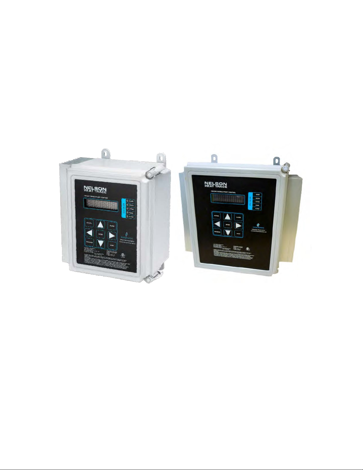
NELSON
CM-2201/CM-2202
HEAT TRACE CONTROLLERS
Installation and Operating Instructions
Page 2

Table of Contents CM-2201/CM-2202
1.0
Introduction
1.1 Getting Started
4
2.0
3.0
4.0
5.0
General Application Information
Installation
Initial Set-up
5
3.1
Selecting Installation Location
3.2
Mounting
3.3
Wiring
5
4.1 Display Modes
4.2
Password Protection
4.3
Security Levels
General Operation
5.1 Display
5.2 Keypad
5.3 LED Functions
5.4 Monitoring
5.5
Alarm Management
5.6
Current-Limiting Feature
4
6
5.7 Ground Faults
5.8 Soft Start Feature
6.0
7.0
Control Modes
6.1
On-Off Control
6.2
Proportional Control
6.3
Forced Control Feature
Programming
7.1 Setpoints
7.2
7.3 System Setup
Heater Setup
8.0
Communications
8
9
15
©2018 Nelson H eat Tracing Systems www.nelsonheaters.com GA2497 Rev.6
Page 3

CM-2201/CM-2202 Table of Contents
9.0 T
10.0
roubleshooting
9.1 Operator Checks
9.2 Ground Faults
9.3 RTDs
9.4 Common Warnings/Al ar ms
Maintenance
Appendix A – Specifications 21
Appendix B – Wiring Diagrams 22
Appendix C – Typical Installation Diagram
Appendix D – Mounting Details 25
Appendix E – Modbus Address List 26
16
20
24
Appendix F – ASCII Table 38
Appendix G – RTD Tables 39
Appendix H – Warranty 48
©2018 Nelson H eat Tracing Systems www.nelsonheaters.com GA2497 Rev.6
Page 4

Introduction CM-2201/CM-2202
1.0
Introduction
The Nelson Heat Trace CM-2201 is designed to monitor and
control one heating circuit in ordinary and Class I, Division 2,
Class I, Zone 2, and Zone 2 hazardous locations.
The CM-2202 can monitor/control two heating circuits in
those same locations.
This manual provides information pertaining to the
installation, operation, testing, communications and
maintenance of these controllers. See Appendix A for
detailed specifications
1.1
Getting Started
The CM-2201/CM-2202 is typically connected to external
RTDs, power or communication based on Appendix B and
C. Detailed set-up of the operating/control/monitoring
program is entered throughout the following sections.
For addition help, call Nelson technical support or follow the
Troubleshooting section.
General Application Information CM-2201/CM-2202
2.0
General Appl i cati o n Inf or ma tio n
The CM-2201/CM-2202 are designed to operate on input
voltages between100and277Vacand50/60Hz. Load
switching is handled by a 2-Pole solid-state relay and can
control resistive loads of 30A continuous @ 40°C
ambient.
The CM-2201/CM-2202 are designed to control heating
circuits by monitoring one or two temperature inputs for
each circuit via industry standard 3-wire, 100Ω,
RTDs. The two separate RTDs for each
utilized to customize the temperature control inputs.
Several different modes are user
sensor failure operational
TheCM-2201 and CM-2202 can be operated in
temperatures of -40°F to +104°F (-40°C to +40°C)
circuit maybe
selectable as well as the
mode.
Platinum
.
©2018 Nelson H eat Tracing Systems www.nelsonheaters.com GA2497 Rev.6
4
Page 5

CM-2201/CM-2202 Installation and Initial Setup
3.0
Installation
The CM-2201/CM-2202 must be installed only in areas for
which it has been approved and in accordance with all
applicable electrical codes and ordinances. All conduit entry
holes must be appropriately installed and sealed to
ingress protection rating.
Do not install this unit prior to functional testing if shipping
container or internal packaging shows signs of damage.
Notify the appropriate individuals immediately if damage is
suspected.
3.1
Selecting Installation Location
The CM-2201/CM-2202 should be installed in an area
protected from the elements as much as possible. It is
possible to install the unit in unprotected areas but such
often limits maintenance/access. Further, installation in
unprotected areas must be carefully considered to ensure it
is always in operating conditions consistent with
specifications. See Appendix A for additional details.
3.2
Mounting
The CM-2201/CM-2202 should be mounted at a convenient
height to suit operator interaction.
(See Appendix D for mounting details.)
Conduit entries should be made in the bottom of the
enclosure to
from moisture
and the use of suitable bushings is required to maintain the
environmental ratings.
3.3
Wiring
Electrical wiring diagrams and schematics are provided in
Appendix B and C of this manual. Ensure that all wiring
and connections are in accordance with applicable wiring
codes. Enclosure grounding must be in accordance with
applicable wiring codes for non-metallic devices.
The power supply for the CM-2201 is derived from the
power provided for the load. However, the power supply for
the CM-2202 can be provided independent of the
supply for the loads being controlled. For
power supply for the CM-2202 can be 120 VAC while the
loads being controlled can be 277 VAC.
supply for the CM-2202 may also be
the loads being controlled – this is
connecting appropriate jumpers.
maintain
prevent damage to the internal electronics
intrusion. Conduit entries should be drilled
power
example, the
Further, the power
derived from either of
implemented by
4.0
Initial Set-Up
Upon initial power-up, the CM-2201/CM-2202 display will
run self-check, display the software version and then start
the main program. Default settings are set to disable
heating cables, (See 7.0 Pro gr ammin g to ena ble he ater s
and program set points.)
4.1
Display Modes
This feature determines what messages and functions
are displayed during normal operations. If set to “normal
user,” only basic information is displayed. If set to
“advanced user,” all controller information is displayed.
Each parameter shown in this manual will list the Display
Mode required to view information and access each function
during programming.
4.2
Password Protection
The CM-2201/CM-2202 may have password protection
enabled to ensure that sensitive operating parameters are
not inadvertently adjusted. If password protection is
enabled, the user will be prompted to enter a valid value to
access any protected features. The user may also replace
the default password value (1234) with their own unique
value for greater protection of operational parameters.
4.3
Security Levels
CM-2201/CM-2202 has two levels of security. The high
level
(Advanced Display) requires password protection.
Disabling
menu will
parameter can
At this level all
are open.
The low level (Normal Level) does not give access to
parameters settings, but certain parameters (such as
temperature, current, GFI, etc.) are open for monitori ng.
If the password is “Enabled”, going directly to the
parameter to be changed, and pressing the ‘up’ or ‘down’
arrow, will cause the controller to ask for the password. If
correctly entered then
saved. The password will
automatically re-enabled. When disabled the password does
not need to be entered to change and save parameters.
the password from the Password Enable/Disable
keep the password disabled indefinitely – any
be changed without the use of a password.
the functions and monitoring parameters
:
the parameter can be changed and
stay disabled for 15 min, then be
©2018 Nelson H eat Tracing Systems www.nelsonheaters.com GA2497 Rev.6
5
Page 6

General Operation CM-2201/CM-2202
5.1
Display
The CM-2201/CM-2202 utilizes a 2-line x 16-character
alphanumeric display viewable from the front keypad. The top
line is reserved for the function or operation and the
bottom line displays the value range.
5.1.1
The CM2201 monitors one heating circuit consisting of load
(typically a heating cable) and controls the load
temperature of the item being heated
provided via one or two RTD’s
connected to the controller.
Actual
Right
To review the statistics that have been collected, press
until “Statistics” is displayed then press
scroll through the various statistics.
To change the control and monitoring settings (including
alarm settings), press the
Left
arrow to scroll through the various settings. Any
setting can be altered by pressing the
Note that a 4-digit password may
certain settings – when
leftmost digit –
or the
second leftmost digit using the
will flash until adjusted using
arrows. When the last digit has been selected, press Enter
and then changes will be allowed to the setting. Once the
setting is adjusted, press the
To view alarms, press the
Left
arrow to scroll through the various alarms. Alarms
that are not active can be erased
key.
Navigation for CM2201
until “Operating Values” is displayed, then press
or
Left
arrow to scroll through the various values.
required, the cursor will flash on the
Down
use the
arrow to decrease it. Move the cursor to the
Up
based on the
(typically a pipe) as
attached to the pipe and
To monitor the load, press
Right or
Program
arrow to increase this digit value
Alarms
key and then
Up
be required to change
Right
or
Up/Down
Enter
key to store it.
key and then Right
by pressing the
or
Down
Left
arrow and it
Left
Reset
Actual
arrow to
Right
arrow.
or
or
5.1.2
Navigation for CM2202
The CM2202 can monitor/control two separate heating
circuits (channels). The controller defaults to Channel 1
upon first start-up. All par am eter s for Chann el 1 can be
displayed and modified using standard techniques
as described for the CM2201 in Section 5.2.1.
To change to Channel 2, simply press the “Actual”
key and then Right arrow – the active channel will
be displayed. To change the channel, press the Up
arrow.
In general, when the active channel is displayed (e.g.
"CH.2"), the ch annel can be chan ged by pr essin g the
Up or Down arrow.
©2018 Nelson H eat Tracing Systems www.nelsonheaters.com GA2497 Rev.6
6
Page 7

CM-2201/CM-2202 General Operation
5.2
Keypad
The keypad is “capacitive” touch sensitive and keys are
activated by simply touching the area of the desired key with a
finger, even when wearing gloves. Note that a stylus or other
item used to touch the keypad will usually not activate the keys.
5.4
LED Functions
LED indicators will show the status of the respective
The power LED will be illuminated when the
connected to a source voltage. The heater LED will be
illuminated when voltage is applied to any heater. The system
LED will illuminate if there is an internal hardware issue with the
controller. The comm LED will illuminate when the controller is
sending data through external communication. The alarm LED
will flash when there is a current active alarm condition or any
circuit; the alarm LED will illuminate solid when an alarm was
previously present but is not currently active.
5.5
Monitoring
By touching the “
the controller will scroll through all the active parameters.
5.6
Alarm Management
All alarm(s) will be saved in the alarm log. If no alar m s are
active (alarm LED solid red) the Alarm LED can be turned off by
touching “Reset” once for every alarm that previously occurred.
If any alarm is active (alarm LED flashing red) the user cannot
reset the alarm. The two alarm relays are SSR type. To set the
contacts of the relays go to Settings – Heater Setup – Alarm
contact. By choosing up/down arrow, the contacts can be
selected to function as Normally Open or Normally Closed.
Press “Enter” to save the selection. (See 7.2.12 for f urther
information on the Alarm contacts setting).
Actual”
functions.
controller is
button follow the arrow and
Power-Limiting Feature
The Power-Limiting feature operates similarly to the
Start in that it restricts the amount of time the cable is
energized during any given period thereby reducing the
average current draw of the cable during that period.
For example, if a cable normally draws 8 Amps, but current
limit is set to 6 Amps, then the cable would be energized
only 75% of the time.
5.7
Ground Faults
Ground faults typically are the result of damaged or
improperly installed cables which allow current-carrying
conductors/ surfaces/pa rt s to b e in co nta ct wi th gr ou nd ed
objects.
For example, if a heating cabl e has bee n secur ed to a pipe
with a clamp, and if the clamp has bee n overtig hte ned,
then the ground braid and/or the pipe may come in
contact with current carrying parts within the cable. This
would result in current leakage to ground through the
ground braid of the cable and/or the pipe itself. This type of
fault can eventually become serious, resulting
overheating/fire/shoc k hazar ds. Current leakage to
can be monitored by electronic circuitry and the SPC/DPC can
be programmed to either alarm or trip when leakage
current exceeds the specified maximum
allowable amount.
5.9 Soft-Start Feature
The Soft-Start feature enables self-regulating cables to
be ener gized at low temperatur es without causing excessive
load on the electrical system and extending cable life by
reducing cable internal heat ing due to inrush cu r rent s . The
resistance of self-regulating cables decreases as the
cables get colder, which results in higher current and can
result in brea ker trips if temp eratures are ve ry cold and
the instal led le ngt h of c ab le is long . The Soft-Start feature
operates by initially only energizing the cable for a very short
period of time – while the current draw may be high du ring
this period, the period is usually short enough to reduce
average load on the elect rical syste m .
This short energizatio n p eriod is repeated and eventually
increased; after a few minutes, the cable is usually warm
enough such that the resistance has increased and the
current decreased to the point where it c an be conti nuou s ly
energized.
Soft-
in
ground
©2018 Nelson H eat Tracing Systems www.nelsonheaters.com GA2497 Rev.6
7
Page 8

Control Modes CM-2201/CM-2202
6.0
Control Modes
The CM-2201/CM-2202 allows the user to select different
control modes based on their individual process control
parameters.
6.1
On-Off Control
This control method simply energizes the cable until the
actual monitored temperature rises to the setpoint value
plus half the deadband value (upper limit). The cable is then
de-energized until the actual monitored temperature
setpoint value minus half the deadband value. Note that this
type of control can result in some temperature “overshoot;”
this is because the cable is de-energized
temperature reaches the upper limit.
in the cable continues to transfer
the pipe temperature to
Similarly, there can
6.2
Proportional Control
This control method uses the typical proportional
control algorithm wherein the cable is cycled on and off at a
rate
proportional to the difference between the setpoint value
and the actual monitored temperature. As the difference
between the setpoint value and the actual
monitored
cable is
reduce the
assoc iated with
energized increases proportionately. This helps
drops to the
when the monitored
However, the residual heat
to the pipe, and this will cause
increase slightly above the upper limit.
be some temperature “undershoot.”
temperature increases, the amount of time the
“overshoot” and “undershoot” commonly
On/Off control.
6.4 Forced Control Feature
This control me thod sim pl y allow s the user to for ce the cab le on or
off as desired using an external signal (e.g. +5 VDC or 24 VAC)
applied to the IN and G terminals or an external dry contact across
the +5V and IN terminals. The External Disable must be set to
“ON” to allow for external control, at which point the controller
operates as follows:
A) If the Temperature setpoint is “OFF” or “None”, then the
heater gets energized by applying the external signal or closing the
external contact.
B) If the Temperature setpoint is a specific value (ex. 55C),
then the setpoint will be maintained as per normal operation ONLY
when the external signal is present, or the external contact is
closed – otherwise, the heater will be disabled.
©2018 Nelson H eat Tracing Systems www.nelsonheaters.com GA2497 Rev.6
8
Page 9

CM-2201/CM-2202 Programming
7.1 Program-Setpoints
7.1.1
Setpoint Value
This message displays the name of the sub-menu when
entered.
7.1.2
This value sets the control setpoint temperature for
all operating modes. For On-Off control, the circuit is
energized if the control temperature is less than the
maintain temperature minus the deadband. The circuit
is
greater than the maintain temperature plus the
deadband. If maintain temp
heater circuit will have temperature
control temperature. If the maintain
then the heater circuit will have no
monitoring or control.
7.1.3
This value sets the Low Temperature Alarm setpoint. It must
be less than the maintain temperature minus the
To disable this alarm set the value to “Off’.
measured temperature of either RTDA or RTD
activated) is less than or equal to this setpoint, the
Low Temperature Alarm is activated and a “LOW TEMP
ALARM” message is added to the alarm stack. This alarm
deactivates when the temperature rises above the alarm
setpoint value.
1.
Display Mode: All
2.
Range: N/A
3.
Default: N/A
Maintain Temp
de-energized if the control temperature is
1.
Display Mode: All
2.
Range: -50 to 500°C, none or -58°F to 932°F,
none, Off
3.
Default: 10° or 50°F
Low Temp Alarm
1.
Display Mode: All
2.
Range: -50C to Maintain Temperature, Off, -58°F to
Maintain Temperature, Off
3.
Default: 5°C or 41°F
4.
Restrictions: Message does not exist if Maintain
Temperature is set to Off.
is set to None then the
monitoring with no
temp is set to Off
temperature
Deadband.
When the
B (if
7.1.4
High Temp Alarm
This value sets the High Temperature Alarm setpoint.
It must be greater than the maintain temperature plus
deadband. To disable this alarm set the value to
“Off”
When the measured temperature of either RTDA or RTDB
(if activated) is greater than or equal to this setpoint, the
High Temperature Alarm is activated and a “HIGH TEMP
ALARM” message is added to the alarm stack. The alarm
deactivates when the temperature falls below this alarm
setpoint.
7.1.5
This value sets the Low Current Alarm setpoint. It must
be less than the high current alarm setpoint. To disable
this
is
Alarm
message is
deactivates when
alarm setpoint. Note:
heater at 100% power. If
Current Limiting is enabled, all
will be scaled to 100% power, based
resistive load, before being compared to the
setpoint.
1.
Display Mode: All
2.
Range: Maintain Temperature to +500°C,
Off,
Maintain Temperature to +932°F, Off
3.
Default: Off
4.
Restrictions: Message does not exist if
Maintain
Low Current Alarm
alarm set the value to “Off’. When the heater current
less than or equal to this setpoint, the Low Current
is activated and a “LOW CURRENT ALARM”
added to the alarm stack. The alarm
1.
Display Mode: All
2.
Range: 0.1A to High Current Alarm value, Off
3.
Default: Off
Temperature is set to Off.
the Heater Current rises above this
This setpoint is based on the
Proportional Control or
current measurements
on a constant
alarm
©2018 Nelson H eat Tracing Systems www.nelsonheaters.com GA2497 Rev.6
9
Page 10

Programming CM-2201/CM-2202
7.1.6
High Current Alarm
This value sets the High Current Alarm setpoint. It must
be greater than the low current alarm setpoint. To
disable this alarm set the value to “Off’. When the
heater current is greater than or equal to this setpoint,
the High Current
CURRENT ALARM” message
stack. The alarm deactivates when
falls below this alarm setpoint. This
on the heater at 100% power.
If Proportional Control or Current Limiting is enabled,
current measurements will be scaled to 100%
all
power, based on a constant resistive load, before being
compared to the
1.
Display Mode: All
2.
Range: Low Current Alarm value to 30.0A, Off
3.
Default: Off
7.1.7
Ground Fault Alarm
This value sets the Ground Fault Alarm setpoint. It must be
less than the ground fault trip setpoint. To disable this
alarm set the value to "Off'. When the Ground Fault Current is
greater than or equal to this setpoint, the Ground Fault
is activated and a "GROUND FAULT ALARM" message
added to the alarm stack. The alarm deactivates when
Ground Fault Current falls below this alarm setpoint.
1.
Display Mode: All
2.
Range: 10 to Ground Fault Trip, Off
3.
Default: 30mA
7.1.8
Ground Fault Trip
This value sets the Ground Fault Trip setpoint. It must be
greater than the ground fault alarm setpoint. To disable this
trip alarm set the value to “Off’. When the Ground Fault Current
is greater than or equal to this setpoint, the
de-energized, the Ground Fault Trip Alarm
“GROUND FAULT TRIP” message is added
stack. This is a latching alarm and trip. When
of the alarm has been corrected, the circuit may
energized by the manual reset function.
1.
Display Mode: All
2.
Range: Ground Fault Alarm to 500mA, Off
3.
Default: 50mA
©2018 Nelson H eat Tracing Systems www.nelsonheaters.com GA2497 Rev.6
Alarm is activated and a “HIGH
alarm setpoint.
is added to the alarm
the heater current
setpoint is based
Alarm
is
the
heater circuit is
is activated and a
to the alarm
the cause
be
7.1.9
Low Voltage Alarm
This value sets the Low Voltage Alarm setpoint. It must be
less than the high voltage alarm setpoint. To disable this
alarm set the value to “Off’. When the Line Voltage is less
than or equal to this setpoint, the Low Voltage Alarm is
activated and a “LOW VOLTAGE ALARM” message is added
to the alarm stack. The alarm deactivates when the Line
Voltage rises above this alarm setpoint.
Low Voltage Alarm Continued
1.
Display Mode: All
2.
Range: 85VAC to High Voltage Alarm, Off
3.
Default: Off
7.1.10
High Voltage Alarm
This value sets the High Voltage Alarm setpoint. It must
be greater than the Low Voltage Alarm setpoint. To
disable this alarm set the value to “Off’. When the Heater
Voltage is greater than or equal to this setpoint, the High
Voltage Alarm is activated and a “HIGH VOLTAGE ALARM”
Message is added to the alarm stack messages. The
alarm
this alarm
deactivates when the Heater Voltage drops below
setpoint.
1.
Display Mode: All
2.
Range: Low Voltage Alarm to 280VAC, Off
3.
Default: Off
7.2
Program- Heater Setup
7.2.1
Heater Setup
This message displays the name of the sub-menu when
entered.
7.2.2
This selection enables control and monitoring of the
heater circuit. Setpoints and measured value messages
cannot be
“No” if the
1.
Display Mode: Advanced
2.
Range: N/A
3.
Default: N/A
Heater Enable
accessed unless the heater is enabled. Select
1.
Display Mode: All
2.
Range: Yes, No
3.
Default: No
circuit is not used.
10
Page 11

CM-2201/CM-2202 Programming
7.2.3
Heater ID
This selection allows for user defined Heater
Identification.
for each heater
alphanumeric
from left to right. The cursor indicates which character is
selected. Press the [SELECT UP/DOWN] arrow keys
being
to change the character. Move to the next character by
pressing [NEXT] arrow. Press [ENTER] in the last character
position to save
1.
Display Mode: Advanced
2.
Range: 16 Characters (CM-2201)
12 Character s (CM-2202)
3.
Default: Blank
7.2.4
Heater Type
This selection allows the user to set which type of
heati ng cable is b e ing used. Self regu la ting heat ing cable
should not be used with proportional control, soft-start
mode, or Power limiting; for this reason these options
are unavailable when heater type is set to self
regulating. When heater type is set to fixed resistance all
control options are available. Display Mode: Advanced
1.
Display Mode: Advanced
2.
Range: Self Regulatin g, Fixed Resistance
3.
Default: Fixe d Resistance
7.2.5
External Disable
This selection sets the response of the heater circuit to the
Override inputs. The Override inputs respond to contact
closure. If the Override is set to “Disable”, the override inputs
are ignored, and control of the heater circuit operates
normally based on the measured temperature and maintain
temperature setpoint. If the Override is set to
“Enable”, an
the heater Off.
closed, the heater control resumes in normal manner.
1.
Display Mode: Advanced
2.
Range: Enable, Disable
3.
Default: Disable
It provides a unique, identifiable tag or label
circuit. The Heater Name allows up to 16
characters which are entered one at a time
the Heater ID.
open contact on the override inputs forces
When the contact on the override input is
7.2.6
Deadband
The Deadband is defined as the difference between the set
point temperature and the actual maximum temperature
that is ideally allowed in excess of the setpoint
temperature Decreasing the deadband increases the
temperature control
switching frequency.
1.
Display Mode: Advanced
2.
Range: 1 C° to 5 C°, 1 F° to 10 F°
3.
Default: 2 C° or 5 F°
4.
Note: Deadband is disabled for Proportional
Control
7.2.7
Control Type
This selection determines the type of control
method used
or Proportional
available for all heating
mode is only available for
devices.
7.2.8
This selection sets the maximum average current limit
allowed for the heater circuit. It is useful for reducing
the
will
for a
draw to the
1.
Display Mode: Advanced
2.
Range: On-Off, Proportional
3.
Default: On-Off
4.
Selection does not exist if Heater type is set to
Self regulating.
5.
Selection does not exist if Maintain Temperature
set to Off.
is
Power Limit
power output of fixed resistance heaters. The load
be turned on for a period of time and then turned off
period of time to maintain the average current
1.
Display Mode: Advanced
2.
Range: 20% - 100%, Off
3.
Default: Off
4.
Note: The value range is in 10% increments.
accuracy but also increases the heater
mode.
by the controller, either On-Off (Deadband)
Control. The On-Off control mode is
devices. Proportional Control
series type heating
value set.
©2018 Nelson H eat Tracing Systems www.nelsonheaters.com GA2497 Rev.6
11
Page 12

Programming CM-2201/CM-2202
7.2.9
Soft Start Mode
This function ramps the heater output from Off to nominal
current of the heater over the set soft start cycle
time. It
regulating
the load will
function.
7.2.10
This selection determines how the control temperature is
utilized by the RTD inputs.
−
−
−
−
−
−
is useful for reducing inrush currents of self-
heaters. At the end of the soft start cycle time,
no longer be controlled by the soft start
1.
Display: Advanced
2.
Range:10 to 999 seconds, Off
3.
Default: Off
RTD Operation
In One RTD Mode, the temperature is based on the
measured temperature from RTD-A.
In Backup Mode, control temperature is based on RTD-A.
for any reason RTD-A fails, then RTD-B takes over.
If
In Average Mode, the control temperature is based on the
average of RTD-A and RTD-B measured temperatures.
In Lowest Mode, control temperature is based on the
lowest
In Highest Mode, control temperature is based on the
highest of the two temperature measurem ents.
In High Temp er ature Cut off Mode, contr ol temperature is
based on RTD-A, but if the temperature from RTD-B
exceeds
turned Off and a
activated. The High Temperature
operate in one RTD mode if the high
is turned Off.
Functions requiring two RTDs to operate, such as Average, Lowest, Highest and High Temperature Cut off, will operate in One RTD mode if one of the two RTDs fail.
1.
2.
3.
Restrictions
Temperature is set to Off.
of the two temperature measurements.
the high temperature alarm, the heater is
Display Mode: Advanced
Range: One RTD, Backup, Average, Lowest,
Highest,
Default: One RTD
high temperature alarm is
cut off mode will
temperature alarm
High Temperature Cut off
: Message does not exist if Maintain
during this
“ALARM
System Status
alarm,
and press
value to “Off”. The
heater is forced off for
trip. Auto Test decreases
warning of problems that
until the heater was needed.
1.
2.
3.
7.2.11
This selection sets the controllers fail-safe mode. The
controller detects if RTD-A has failed and will use RTD-B
available. If RTD-B is not installed or has also
if
failed, the
as selected in this
where there is no hazard from
may select “On” to operate the heater
and prevent freeze up.
potential hazard from
to de-energize the circuit
available.
1.
2.
3.
7.2.12
This selection sets the operating mode of the external
alarm indicator.
will be open when there is no power applied to the unit (this
can be useful for signaling loss of power to the unit) OR there is
an active alarm OR there previously was an active alarm that
has not been acknowledged.
The alarm contacts function as follows:
period, the Auto Test Alarm is activated and an
DURING AUTO TEST” message is added to the
messages. This is a latching alarm. To clear the
locate the alarm message in the Alarm menu
[ENTER]. To disable this feature, set the
Auto Test Cycle does not operate if
any reason, including ground fault
maintenance by providing an early
would otherwise go undetected
Display Mode: Advanced
Range:1 to720 hours, Off
Default: 24 hours
RTD Failure Mode
heater will be set to its fail-safe state
mode. For freeze protection
For processes where there is a
overheating, you may select “Off”,
Display Mode: Advanced
Range: On, Off
Default: Off
Restrictions:
Temperature is set to Off.
Alarm Contact
Message does not exist if Maintain
By setting the contacts to NC, these contacts
overheating, you
continuously
until one of the RTD’s becomes
7.2.11
Auto Test Cycle
This value sets the frequency at which the Auto Test Cycle is
activated. Auto Test is a feature that exercises the system by
automatically applying power to the heater at
specified time intervals. If an alarm condition is detected
©2018 Nelson H eat Tracing Systems www.nelsonheaters.com GA2497 Rev.6
1.
Display Mode: Advanced
2.
Range: Normally Open, Normally Closed
3.
Default: Normally Open
12
Page 13

Programming CM-2201/CM-2202
7.3 Program– System Setup
7.3.1 System Setup
This message displays the name of the sub-menu
when entered.
1. Display Mode: Advanced
2. Range: N/A
3. Default: N/A
7.3.2
Password
This selection determines if password protection is
required
show “disable” if program access is currently enabled
and show “enable” if program access is currently
disabled.
7.3.3
This selection allows the user to change the default
password. The user is prompt to re-enter the old
password, press [ENTER]. If correct, the user is prompt to
enter the new password, press [ENTER]. The user is then
prompt to re-enter the new password. If the user does
not enter the new password and press [ENTER] then the
password does not change.
7.3.4
This selection determines the unit of measure for
temperature values. All temperatures are displayed in
the
Fahrenheit degrees (F°).
for programming changes. The display will
1. Display Mode: All
2. Range: Enable or Disable
3. Default: Enable
Change Password
1. Display Mode: All
2. Range: Yes, No
3. Default: No
Units
selected units of either Celsius degrees (C°) or
1. Display Mode: Advance
2. Range: Celsius, Fahrenheit
3. Default: Celsius
7.3.5 Operational Costs
This value sets the cost per kWh of electrical power. This is
used to calculate energy costs for operating this control
circuit.
7.3.6 Display Mode
This selection determines what messages are displayed by
the controller for operations personnel. If set to
“advanced
“normal user”, only the basic messages are displayed.
Each message listed throughout this manual shows the
Display Mode required
to see the message. “Advanced only” indicates that the
display mode must be set to “advanced user” to view the
message.
7.3.7 Default Display
This function specifies the information that will be
displayed when no key has been pressed for the Display
Timeout interval as described below.
VALUE
System status
Heater status Alarm status of
Heater temp Temperature of
1. Display Mode: Advance
2. Range: $0.01 to 1.00
3. Default: $0.05
user”. all messages are displayed. If set to
1. Display Mode: All
2. Range: Normal, Advance
3. Default: Advance
1. Range: System Status, Heater Status, Heater Temp
2. Default: system status
3. Restrictions: Temperature messages are
not
displayed if Maintain Temperature is set
to Off.
INFORMATION
DISPLAYED
Alarm status of
all the heaters
the heater
the
heater
©2018 Nelson H eat Tracing Systems www.nelsonheaters.com GA2497 Rev.6
13
Page 14

Programming CM-2201/CM-2202
7.3.8 Display Timeout
This function sets the length of time from the last key
press, to automatically return to the Default Display
information.
1. Display Mode: Advance
2. Range:5 to 600 seconds, Off
3. Default: 120 seconds
7.3.9 Modbus Address
This selection sets a unique address to ensure only one
CM- 2201 attempts communications with the master unit
at any time. See Section 8.0 for complete information on
Modbus communications.
1. Display Mode: Advance
2. Range: 1 to 255 to accommodate multiple
3. Default: 1
Selecting “Off’ disables this function.
devices on same network.
7.3.10 Baud Rate
Sets the communication baud rate for the RS485 serial
port. All controllers connected to the same data highway
must operate on the same baud rate.
1. Display Mode: Advance
2. Range: 2400, 4800, 9600, 19200
3. Default: 9600
7.3.11 Reset Module
This selection resets controller memory parameters to
factory default values. If the controller’s memory
becomes corrupt, resetting the module will force the
controller to overwrite each register and may correct
any problems that
1. Display Mode: Advance
2. Range: yes, no
3. Default: no
7.4 Program- System Test
7.4.1 System Test
This message displays the name of the sub-menu when
entered.
©2018 Nelson H eat Tracing Systems www.nelsonheaters.com GA2497 Rev.6
1. Display Mode: Advanced
2. Range: N/A
3. Default: N/A
exist.
7.4.2 Alarm Output Test
This function is used for testing and commissioning
purposes allowing the alarm output to be forced On either
for a short period of time or continuously. At the end of the
specified time duration, the testing option is
automatically
operate if the alarm configuration is set to disable and the
message “ALARM DISABLED” will appear.
1. Display Mode: Advanced
2. Range: 1-24 hours, Disabled, Continuously
3. Default: disabled
disabled. The alarm test function will not
7.4.3 Heater Test
This function overrides heater control for
maintenance purposes. For normal operation, set to
“disable”. If a period of time is selected, the heater is
forced On or Off for the selected interval. If “continuous” is
selected the heater is forced On until “disable” is selected.
1. Display Mode: Advanced
2. Range: 1-24 hours, Disabled, On Continuously
3. Default: disabled
7.4.4 Ground Fault Test
This function will test the ground fault trip function of
the controller to ensure proper operation. When
selected, the controller will generate an artificial
ground fault current; if
sensed as being greater than 30
The GF test function will verify actual ground fault
current and heater trip. Status of the test will be
displayed as pass or fail. If this test has been
invoked by the “Now” option and it passes, the user is
prompted to
the load is capable of being re-energized as required. If
this test has been invoked by the “Autotest” option
and it passes, the load is allowed to be reenergized as
required. If this test has been invoked by the Autotest
cycle and it fails, an Autotest alarm is generated but
the load is allowed to be re-energized as required.
1. Display Mode: Advanced
2. Range: Autotest cycle, Now, Disabled
3. Default: Disabled
the ground fault current is
mA, the test passes.
reset the ground fault trip, at which time
14
Page 15

CM-2201/CM-2202 Communications
8.0 Communications
The Nelson Heat Trace CM-2201 supports a subset of the Modbus® RTU protocol format that provides monitoring,
programming, and control functions using Read (03) and Write (05-06) register commands.
General Information
Serial Port:
Baud Rate: User Defined at 2400,
Data Bits: 8
Stop Bits: 1
Parity:
Device Address:
Modbus Registers
For all Modbus register addresses,
Example of checking alarms via Modbus from a remote
terminal.
Controller SETTINGS and Status used on this example:
a. Modbus address 04
b. Baud rate 19200; non-parity; Stop bit 1.
c. High Temperature alarm active
1.
To check if any alarm is activated, send the
following instruction:
2.
The controller will answer with value 0x02 (High
Temperature Alarm) active Alarm
3.
Once the alarm condition has been resolved, the
alarm can be cleared by sending the following
instruction: “04 05 0045 FF00 9C4C”
At this point the controller enters the alarm into
the alarm log memory and clears the active
alarm. To check the alarm log memory, see
below.
©2018 Nelson H eat Tracing Systems www.nelsonheaters.com GA2497 Rev.6
Select the serial port that corresponds to your RS-485 adapter.
USB to Serial adapter may be used for devices without serial connections.
4800, 9600 or 19200
None
User Defined between 1 and 255
see Appendix E.
04 03 0046 0026 2590
04 = controller Modbus number
03 = Modbus function code 3
0046 = start reading from data address
70
0026 = the next 38 addresses
2590 = CRC
04 =controller Modbus number
05 = Modbus function code 5
0045 = writing to data address 165
FF00 = erase command
9C4C = CRC
4.
If the command to check if any alarm is
activated (as shown in (1) above) is now sent to
the controller, and assuming no other alarms
have since been activated, the controller will
answer with 0x0000 (no active alarms).
5.
To check the alarm log memory, issue the
following instructions:
04 03 006E 0026 A598
04 = controller Modbus number
03 = Modbus function code 3
006E = start reading from data address
110
0026 = the next 38 addresses
A598 = CRC
6.
The High Temperature Alarm will be listed
here, so the controller will answer 0x02. The
Alarm log can hold 20 alarms. After 20 alarms
the oldest alarm will be erased to allow for
storage of the new alarm. To erase all alarms on
alarm log, see below.
7.
To erase all alarms on the Alarm log from the
remote terminal, send the following instruction:
04 05 0097 FF00 3D83
04 = controller Modbus number
05 = Modbus function code
0097 = data address 151 to write
FF00 = command to erase all memory log
3D83 = CRC
Note: The DPC can read up to 45 addresses per command
15
Page 16

Troubleshooting CM-2201/CM-2202
Terminal No.
Description
RA
RTD A Source (RED)
WA RTD A Common(WHT)
RA
RTD A Sense(RED)
GND Bus
Shield
RB
RTD B Source (RED)
WB RTD B Co m m on ( WH T)
RB
RTDB Sense(RED)
9.3
RTDs
9.1
Operator Checks
Upon receipt of the controller, or to check the controller for
an indication of normal operation, follow the operational
procedures shown below. These procedures are designed to
familiarize the operator with the controller and to provide an
u
nderstanding of its operation.
To determine if a fault is associated with the heat tracing,
wiring or the controller, it will be necessary to troubleshoot
the wiring and tracer circuit. If the
Fault re mains, r e mov e po we r fro m th e co ntro l ler an d exchange
it with another controller. This may require some
reprogramming of the new CM2201/CM-2202. Refer to the
following se ctio n s for th e approp riat e topic.
9.2
Ground Fault
Ground fault warning /alarms can be caused by incorrect
installation as well as current leakage resulting from wet
system components or damaged cables.
The CM2201/CM2202 Controller detects ground faults by
summing the outgoing and return trace currents
through an internal current transformer. Under normal
operating
current will be
conditions (no g round fault condition) this
zero. When t here is a flow of current from
one of the trace supply wires to ground, a ground
fault condition occurs.
If a ground fault alarm is present on start-up of a new
installation it is likely due to a wiring error or damaged
cable.
To verify this condition:
a)
Check that the heating circuit neutrals return to
RTD failures after installation can generally be attributed
incorrect wiring or improper installation of the sensor.
Troubleshooting of these failures is a very simple procedure
the proper steps are undertaken in the correct order.
Some specific RTD problems and the correct methods for
troubleshooting are outlined as follows.
1.
RTD Failure Alarm(s)
If the CM2201/CM-2202 controller indicates a failure of an
a)
Ensure that the RTD is a 3-wire 100 (Platinum Type).
TURN THE POWER TO THE CONTROLLER OFF BEFORE
PROCEEDING!
b)
Disconnect the RTD wiring from the input terminals.
c)
Measure the RTD’s resistance between the source (RED) and
sense (RED) leads at the controller (it should not exceed 40
Ω). Excessive lead resistance will cause a RTD FAILURE
ALARM and must be corrected. Look for loose
excessive lead length, or insufficien t wire
as necessary.
d)
When wiring to the CM2201/CM 2202, the terminals are marked as
follows:
GND Bus
terminals,
gauge and correct
Measures the RTD’s resistance between the source (RED) or
sense (RED) lead and the common (WHT) lead of the RTD at
the controller (should be between 60 and 330 Ω depending
on the temperature and the lead resistance. Verify
that the RTD is wired correctly—the heat tracing
will always be terminated in the order: source
common(WHT), sense(RED).
Shield
controllers
(RED),
to
if
RTD:
the controller a nd are no t con nected dir ect ly to
distribution panel. This can be a common
the
problem if the
installation is a retrofit situation.
b)
On paralleled circuits, be certain that ALL neutrals
return. The late addition of a circuit may not be obvious.
Note:
The controller monitors the integrity of the ground
fault(GF) detection. If a fault is detected, the controller
will generate a GFI warning/alarm depend of the settings.
The RTD manufacturer will typically color code the leads
the source and sense being the same color, and the
different color. Ensure that the RTD extension
terminated at one end only, normally using the
provided at the terminal board.
common a
wire shield is
terminal block
with
©2018 Nelson H eat Tracing Systems www.nelsonheaters.com GA2497 Rev.6
16
Page 17

CM-2201/CM-2202 Troubleshooting
Note:
Red triad color code for the RTD connections. Usually,
RED lead is the common connection (same as the White-WhiteRed color scheme) and the White and Black connections may be
used interchangeably.
©2018 Nelson H eat Tracing Systems www.nelsonheaters.com GA2497 Rev.6
Some manufacturers use the common Black-White-
the
2.
Temperature Verification
If you consider that the indicated or displayed temperature is
not correct, the controller and the RTD can be quickly
checked for correct operation. To verify the RTD:
TURN THE POWER TO THE CONTROLLER OFF BEFORE PROCEEDING!
a)
Disconnect the RTD wiring from the input terminals.
b)
To calculate the temperature indicated by the RTD,
measure the resistance from source (red wire) or
sense
the resistance measured between source and sense. This
will give a compensated resistance value that can be
crossAppendix
E or Appendix F. Compare the measured resistance and
cross-referenced temperature value obtained from the
RTD table to the indicated or displayed value. These
should agree to within the accuracy standards of the
CM2201/CM2202 and the RTD.
Note:
Ensure you refer to the correct RTD table for the type
RTD you are using
To verify the Controller:
TURN THE POWER TO THE CONTROLLER OFF BEFORE PROCEEDING!
a)
Disconnect the RTD wiring from the input terminals.
b)
Connect a 100 Ω resistor across the source or
sense
between the
c)
Apply power to the controller. The indicated or
displayed
depending on
RTD TYPE is
have a +/- 10%
(red wire) to commo n (white wir e ) and subtract
referenced to one of the RTD tables found in
terminal and common. Insert a jumper
source and sense terminals.
temperature should be about 32°F (0°C)
the actual resistance of the test resistor if
set to 100 Ω Platinum. Any resistor may
tolerance.
of
3.
Unstable Temperature
An erratic indication of temperature can be caused by several
factors external to the controller. The controller’s
resolution will result in an indicated
couple of degrees if the measured
falls between two discrete values
referred to as quantization error).
If the instability is excessive, check:
a)
Wire used for extension of the RTD should be threewire,
twisted and shielded with the shield grounded at the
controller only. Each of the three lead wires must be of the
same gauge.
b)
The ideal installation has a separate conduit for the RTD
leads (if they have been extended). It is not usually
problem to run low signal levels in the same conduit
the power leads even in high power applications, as
as the RTD wire is a twisted, shielded type with an
insulation rating equal to or greater than the highest
voltage in the conduit. Follow the proper Electrical Code
requirements for your particular installation.
c)
Check the specifications for the particular cable
being used to ensure that it does not have excessive
Capacitance when used in long lengths. This can
cause a
reads and
normally
for all
d)
Check one by one if the all RTD leads are connected to
the connector.
e)
Lastly, it is possible for the RTD itself to fail
on an
should be
probably the
also the least
temperature offset between what the controller
what the RTD actually measures. This again is
not a problem since the controller compensates
but the worst cases of this.
intermittent basis, but this failure mode
considered unusual. This kind of failure is
most difficult to find but fortunately it is
likely as a failure mechanism.
accuracy and
temperature change of a
resistance temperature
(this is sometimes
a
as
long
17
Page 18

Troubleshooting CM-2201/CM-2202
9.4
Common Warnings/Alarms - What to Look for
The CM-2201/CM-2202 has a wide range of warning
and
alarming features that may be selectively enabled or
disabled to allow the monitoring and indication of
trouble
conditions. Described below are the different
warming and
2201/CM-2202, their
warning settings must
alarm will be activated the
activated.
9.4.1
Continuity Failure
The “Cont in uity F a ilure ” al ar m ind ic ate s tha t the curr e nt be in g drawn by the load is less than about 0.5 Amps and hence the load is assumed to be disconnected
9.4.2
High Current Warning/Alarm
This Warning/alarms current levels that are greater than the
HIGH CURRENTWARNING/ALARM setting for the application.
Cause of Warning/Alarm:
•
Warning/Alarm setting too close to normal
operating
•
High in-rush current from “cold start” of self regulating
cable
•
Damaged or partially shorted heating cable
•
“
As built” cable length is greater than design value
9.4.3
Low Current Warning/Alarm
This alarms current levels which are less than the LOW
CURRENT WARNING/ALARM setting.
Cause of Warnings/Alarm:
•
Warning/Alarm setting too close to normal
operating
•
Low sou rce voltage
•
Damaged or inoperative heating cable
•
Open connection—wiring problem
•
SSR or contactor failed open
9.4.4
Overcurrent Trip
If the controller is unable to start the cable due to high
after attempting to soft start it, the controller will
switch off.
Cause of Alarm:
•
Excessive in-rush current
•
Incorrect CM-2201/CM2202 settings
•
Incorrect wiring
•
Damaged cable
alarm conditions available on the CM-
meanings, and possible causes. The
be below alarm settings. If an
two SSR low power will be
current
current
current or
trip its output
9.4.5
Power Limiting (Current Limiting)
This alarm indicates that the solid-state relay is limiting the
average amount of power that is applied to the trace circuit
as defined by the MAXIMUM POWER setting.
Cause of Alarm:
•
Power applied to trace circuit is being limited to
MAXIMUM POWER setting
the
9.4.6
High GFI Warning
This warning ground fault current levels which are greater
than the HIGH GFI WARNING setting.
Cause of Warning:
•
Warning setting too close to normal leakage current
•
Damaged cable insulation and/or moisture present
•
Moisture in junction box
•
Poor splice or termination
•
Moisture provides conductive ground path which allows
ground fault current
9.4.7
GFI Alarm
This value sets the upper limit of allowable ground fault
leakage. Exceeding this limit will result in the output switch
being latched off and the alarm activated to indicate a
ground fault condition.
Cause of Alarm:
•
Trip setting too close to normal leakage current
•
Damaged cable insulation and/or moisture present
•
Moisture in junction box
•
Poor splice or termination
Moisture provides conductive ground path
which allows
9.4.8
Switch Failure
This alarm indicates that the controller senses current flow
when the output switch should
Cause of Alarm
•
Some other devi ce en er gize d heat t race
•
Output switch has failed “closed”
ground fault current
be off.
©2018 Nelson H eat Tracing Systems www.nelsonheaters.com GA2497 Rev.6
18
Page 19

CM-2201/CM-2202 Troubleshooting
9.4.9
High RTD A/ RTD B Temperature Reading
This warning/alarm appear when the temperature exceeds the
HIGH RTD WARNING/ALARM temperature setting.
Cause of Warning/Alarm:
•
Warning/Alarm temperature setting too close to maintain
temperature
•
Flow of hot product
•
Steaming out lines
•
Incorrect tracer wiring
9.4.10
Low RTD A/ RTD B Temperature Reading
This warning/alar m a ppea rs when the te mp e ra ture
decreases below the LOW RTD WARNING/ALARM temperature
setting.
Cause of Warning/Alarm:
•
Warning/Alarm temperature setting too close to maintain
temperature
•
Flow of cold produ ct
•
Empty pipe
•
Damaged, wet, or missing insulation
•
Heating cable not sized properly for the application
9.4.13
High Voltage Warning/Alarm
This warning/alarms voltage levels that are greater than the
HIGH VOLTAGE WARNING/ALARM setting.
Cause of Warning/Alarm:
•
Warning/Alarm setting too close to normal operating voltage
•
Incorrect wiring
•
Power surge
9.4.14
Low Voltage Warning/Alarm
This warning/alarms voltage levels are less than the LOW
VOLTAGE WARNING/ALARM setting.
Cause of Warning/Alarm:
•
Warning/Alarm setting too close to normal operating
voltage
•
Damaged power cable
•
Incorrect VOLTAGE TURNS RATIO
•
“Brown-out” conditions
•
Loss of power to the circuit
9.4.11
RTD A/ RTD B Failure
This alarm indicates a sensor is not operating properly. The
temperature sensor may fail due to an “open” or “shorted”
condition.
Cause of Alarm:
•
Incorrect or damaged field wiring - open leads or excess
resistance (either intermittent or continuous) may be due to
broken or damaged wires or loose terminals.
•
Damaged or inoperative temperature sensors
9.4.12
EEPROM Data Failure
This alarm indicates that the controller has detected a
failure in its non-volatile memory (this is where all of the
controller’s configuration and calibration settings are
stored). This indicates an internal problem and the
CM2201/CM2202 should be replaced and returned to
factory for repair.
the
Cause of Alarm:
•
The CM-2201/CM2202 cannot bypass the failed area of its
memory and has loaded factory defaults into this failed
.
area
©2018 Nelson H eat Tracing Systems www.nelsonheaters.com GA2497 Rev.6
19
Page 20

Maintenance CM-2201/CM-2202
10.0 Maintenance
The CM-2201/CM-2202 should be regularly maintained as follows:
a) Check fit of door gasket and adjust as required. Clean
door gasket.
b) Verify that moisture is not entering enclosure; repair as
required.
c) Check terminals to ensure connections are secure.
d) Check wiring for any signs of overheating.
e) Clean front panel with mild soap on damp cloth.
Warning: Do not use any cloth from synthetic material or
similar. The cleaning process may cause the front label to charge
electrostatically and touching the front panel may generate
s
parks.
©2018 Nelson H eat Tracing Systems www.nelsonheaters.com GA2497 Rev.6
20
Page 21

Appendices CM-2201/CM-2202
Appendix A Specifications
Model: Rating:
Maximum Current:
Enclosure:
CM-2201/CM-2202
110–277Vac,30Amps (Solid State Relays)
30 Amps per Channel 50 or 60 Hz
Solid State Relay (DPST) Normally Open (NO)
4X
Alarm Outputs:
Agency Approval for Hazardous Locations:
cCSAus
Class1, DIV.2, Groups A, B, C, D Class 1, Zone 2: IIC
Temperature Code:
Frequency: Switching:
1.
24 VACto277 VAC@Max.0.5 Amps (Solid State Relay - requires Min. 100mA load)
2. 30VDC@ Max. 0.1 Amps (Solid State Relay- requires Min. 50mAload)
T4 (135 °C)
NEMA
©2018 Nelson H eat Tracing Systems www.nelsonheaters.com GA2497 Rev.6
21
Page 22
Appendices CM-2201/CM-2202
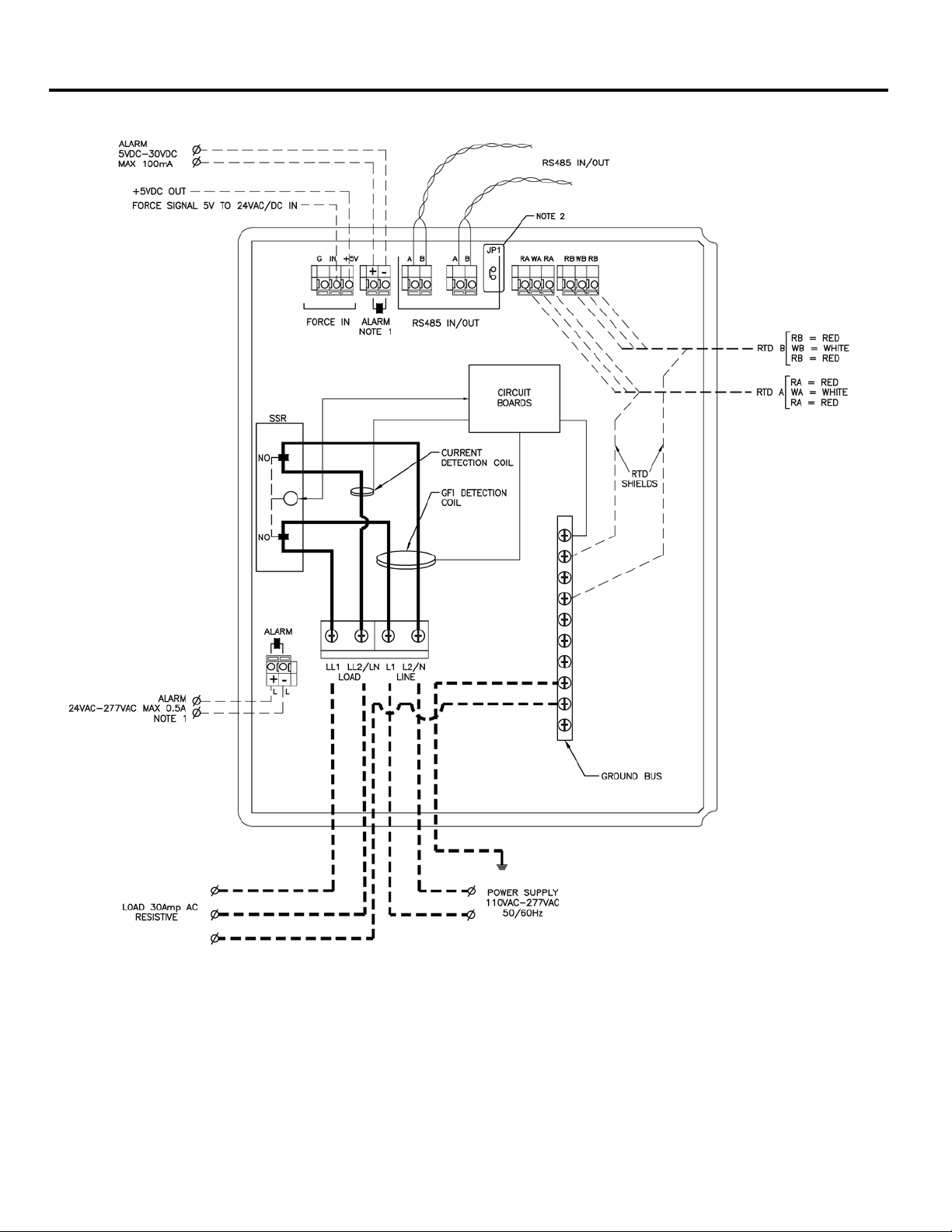
Appendix B CM-2201 Wiring Diagram
Notes:
1. Solid State Contact
2. Install Jumper at JP1 (120 OHM Resistor) on both terminals if CM-2201 is last device on network. Else install jumper on one terminal only of JP1.
3. If “Force “ feature is activated by external “dry contact”, use “+5V” and “IN” terminals; Ground connection is not required. If activated by external voltage signal, use
“IN” and “G” (Ground) terminals as noted.
©2018 Nelson H eat Tracing Systems www.nelsonheaters.com GA2497 Rev.6
22
Page 23

CM-2201/CM-2202 Appendices
Controller Independently Powered
Controller powered in parallel with CH.1
Controller powered in parallel with CH.2
CONN4-L2/N to CONN3-L2/N
CONN5-L2/N to CONN3-L2/N
CM-2202 Wiring Diagram Appendix B
Notes:
1. All Alarms Output are SSR N.O.
2. All RTD’s must have the Shield connected to Ground Bus.
3. Remove Jumper JP1 only if the controller is in RS485 Network AND is not the last unit on the Network.
4. Connect Controller Power Supply as follows;
Connect power supply directly to conn3
©2018 Nelson H eat Tracing Systems www.nelsonheaters.com GA2497 Rev.6
Jumper CONN4-L1 to CONN3-L1
&
Jumper CONN5-L1 to CONN3-L1
&
23
Page 24

Appendices CM-2201/CM-2202
Appendix C Typical Installation Diagram
©2018 Nelson H eat Tracing Systems www.nelsonheaters.com GA2497 Rev.6
24
Page 25

Appendices CM-2201/CM-2202
CM-2201 Mounting Details
CM-2202 Mounting Details
Appendix D Mounting Details
©2018 Nelson H eat Tracing Systems www.nelsonheaters.com GA2497 Rev.6
Page 26

Appendices CM-2201/CM-2202
D.1 Module Setup Group (Read/Write)
Modbus
Data
Length
Register
Address
Bytes
= x per 1°C (-50 to +500)
= x per 1°F (-58 to +932)
= x per 1°C (-50 to +500)
= x per 0.1A (1 to 300)
= x per 1V (85 to 280)
= x per 1 Second (10 to 999)
= x per 1 Hour (1 to 720)
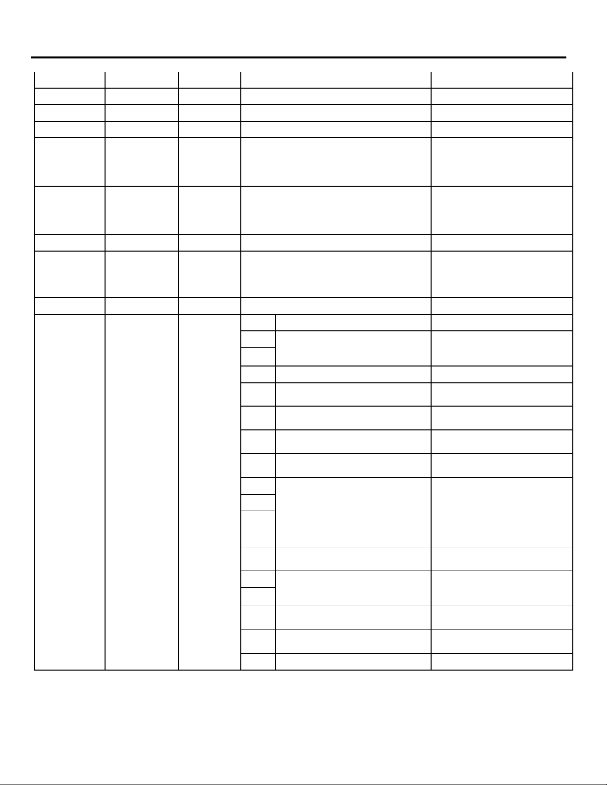
Appendix E Modbus Address List
Variable Name
40001 0 2 Maintain Temp in °F
40002
40003
40004
1 2
2
3 2
40005 4 2
40006 5 2
40007 6 2
40008 7 2
Maintain Temp in °C
2 Low Temp Alarm in °F
Low Temp Alarm in °C
High Temp Alarm in °F
High Temp Alarm in °C
Deadband in °F = x per 1°F (1 to 10)
Deadband in °C = x per 1°C (1 to 5)
Description/Value
Range
= x per 1°F (-58 to +932)
= 32766 if Set to None
= 32767 if Set to Off
= 32766 if Set to None
= 32767 if Set to Off
= 32767 if Set to Off
= x per 1°C (-50 to +500)
= 32767 if Set to Off
= x per 1°F (-58 to +932)
= 32767 if Set to Off
= 32767 if Set to Off
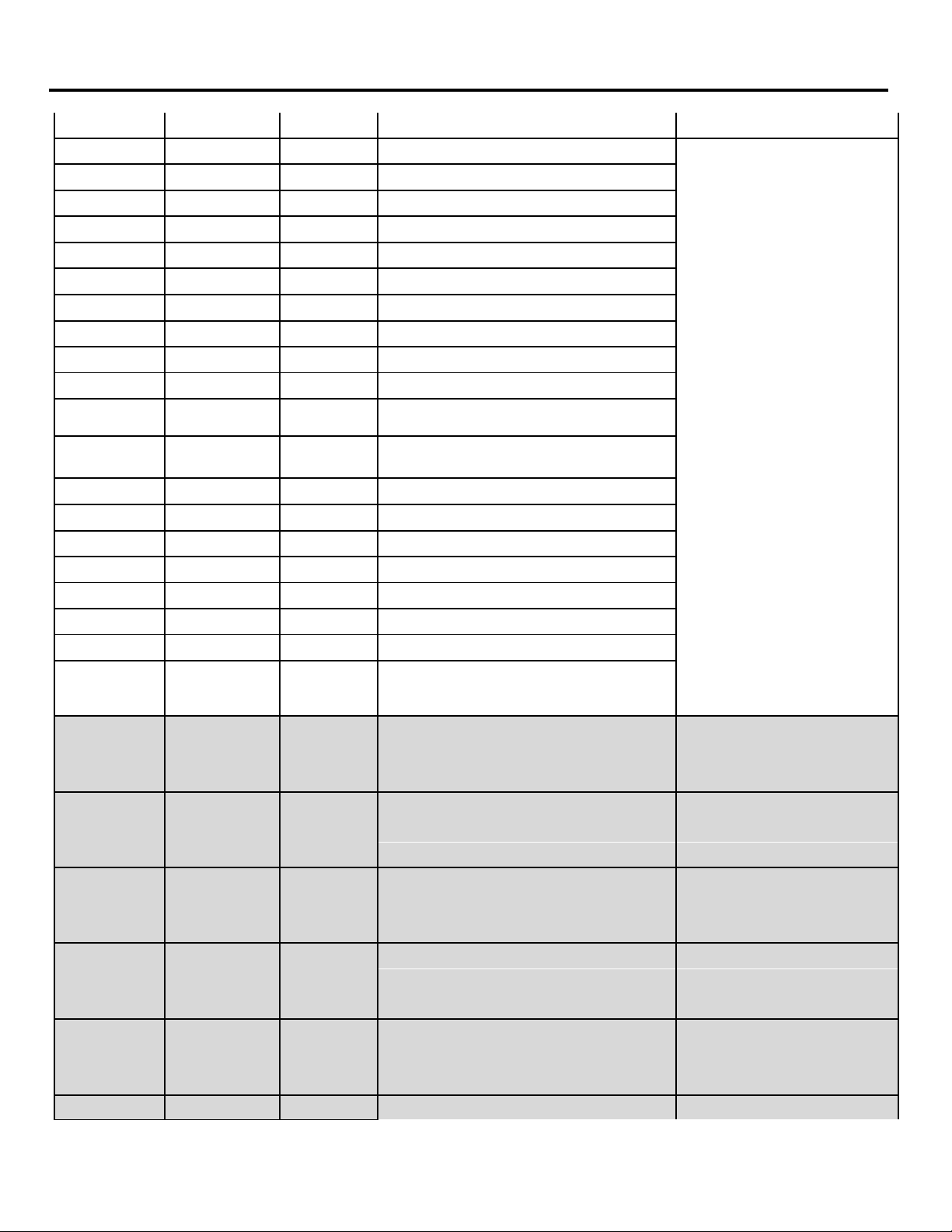
40009 8 2
40010 9 2
40011 10 2
40012 11 2
40013 12 2
40014 13 2
40015 14 2 Power Limit
40016 15
40017 16 2 Auto Test Cycle
40018 17 2 Display Time
Low Current Alarm
High Current Alarm
Ground Fault Alarm
Ground Fault Trip
Low Voltage Alarm
High Voltage Alarm
Soft-Start
2
= 32767 if Set to Off
= x per 0.1A (1 to 300)
= 32767 if Set to Off
= x per 1mA (10 to 500)
= 32767 if Set to Off
= x per 1mA (10 to 500)
= 32767 if Set to Off
= 32767 if Set to Off
= x per 1V (85 to 280)
= 32767 if Set to Off
= x per 10% (1 to 10)
= 32767 if Set to Off
= 32767 if Set to Off
= 32767 if Set to Off
= x per 1 Second (5 to 600)
= 32767 if Set to Off
©2018 Nelson H eat Tracing Systems www.nelsonheaters.com GA2497 Rev.6
26
Page 27
CM-2201/CM-2202 Appendices
= x per 1 Hour (1 to 24)
= 32764 if Set to Disable
16-Character limit (CM-2201)
chart
00 = Auto Test Cycle
10 = Disable
0 = Normally Open
1 = Normally Closed
0 = No
1 = Yes
0 = Disable
1 = Enable
0 = On/Off
1 = Proportional
000 = Single RTD Mode
101 = High Temp Cut-out
0 = Off
1 = On
00 = Auto Test Cycle
10 = Disable
0 = Fixed Resistance
1 = Self Regulating
0 = Normally Open
1 = Normally Closed
Modbus Address List Appendix E
40019 18 2 Cost per kwh = x per $0.01 (1 to 100)
40020 19 2 Reserved
40021 20 2 Reserved
40022 21 2 Reserved
40023 22 2 Alarm Test
=32765 if Set to Continuously
= x per 1 Hour (1 to 24)
40024 23 2 Heater Test
40025 24 2 Reserved
= 32764 if Set to Disable
=32765 if Set to Continuously
40026-40033 25 - 32 16 Heater Name
40034-40042 33 - 41 16 Reserved
bits Variable name
40043 42 2
0
1
2 Reserved
3 Alarm Contact CH.1
4 Enable Heater CH.2
5 External Disable CH.2
6 Control Type (CH.2)
7
8
9
GF Test CH.1
RTD Operation (CH.2)
12-character limit (CM-2202).
See Appendix E for ASCII
01 = Now
001 = Backup
010 = Average
011 = Lowest
100 = Highest
10 RTD Failure Mode (CH.2)
11
GF Test (CH.2)
12
13 Heater Type (CH.2)
14 Alarm Contact (CH.2)
15 Reserved
01 = Now
©2018 Nelson H eat Tracing Systems www.nelsonheaters.com GA2497 Rev.6
27
Page 28

Appendices CM-2201/CM-2202
Modbus
Register
Length
Bytes
0 = °F
1 = °C
0 = No
1 = Yes
0 = Disable
1 = Enable
0 = On/Off
1 = Proportional
000 = Single RTD Mode
101 = High Temp Cut-out
0 = Off
1 = On
0 = Disable
1 = Enable
0 = Normal
1 = Advanced
00 =System Status
10 = Heater Temp
0 = Fixed resistance
1 = Self-regulating
Low Temp Alarm in °F
= x per 1°F (-58 to +932)
Low Temp Alarm in °C
= x per 1°C (-50 to +500)
Deadband in °F
(ch2)
Deadband in °C
Appendix E Modbus Address List
Data Address
40044 43 2
bits Variable name Description/ Value Range
0 Units
1 Enable Heater (CH.1)
2 External Disable (CH.1)
3 Control Type (CH.1)
4
5
RTD Operation (CH.1)
6
7 RTD Failure Mode (CH.1)
8 Enable Password
9 Display Mode
10
Default Display
11
001 = Backup
010 = Average
011 = Lowest
100 = Highest
01 = Heater Status
40201 200 2
40202 201 2
40203 202 2
40204 203 2
40205 204 2
40206 205 2
12
13
14
15 Heater Type (CH.1)
Maintain Temp in °F = x per 1°F (-58 to +932)
(ch2) = 32766 if Set to None
Maintain Temp in °C = x per 1°C (-50 to +500)
(ch2) = 32766 if Set to None
(ch2) = 32767 if Set to Off
(ch2) = 32767 if Set to Off
High Temp Alarm in °F = x per 1°F (-58 to +932)
(ch2) = 32767 if Set to Off
High Temp Alarm in °C = x per 1°C (-50 to +500)
(ch2) = 32767 if Set to Off
Baud Rate
001 = 2400 bps
010 = 4800 bps
011 = 9600 bps
100 = 19200 bps
= 32767 if Set to Off
= 32767 if Set to Off
40207 206 2
40208 207 2
©2018 Nelson H eat Tracing Systems www.nelsonheaters.com GA2497 Rev.6
(ch2)
= x per 1°F (1 to 10)
= x per 1°C (1 to 5)
28
Page 29

CM-2201/CM-2202 Appendices
Low Current Alarm
= x per 0.1A (1 to 300)
Low Voltage Alarm
= x per 1V (85 to 280)
Auto Test Cycle
= x per 1 Hour (1 to 720)
Heater Test
= x per 1 Hour (1 to 24)
(ch2)
= 32764 if Set to Disable
Modbus Address List Appendix E
40209 208
40210 209
40211 210
40212 211
40213 212
40214 213
40215 214 2
40216 215
40217 216 2
40218 217 2 Display Time
40219 218 2 Cost per kwh = x per $0.01 (1 to 100)
40220 219 2 Reserved
40221 220 2 Reserved
40222 221 2 Reserved
40223 222 2
2
(ch2) = 32767 if Set to Off
High Current Alarm = x per 0.1A (1 to 300)
2
(ch2) = 32767 if Set to Off
Ground Fault Alarm = x per 1mA (10 to 500)
2
(ch2) = 32767 if Set to Off
Ground Fault Trip = x per 1mA (10 to 500)
2
(ch2) = 32767 if Set to Off
2
(ch2) = 32767 if Set to Off
High Voltage Alarm = x per 1V (85 to 280)
2
(ch2) = 32767 if Set to Off
Power Limit = x per 10% (1 to 10)
(ch2) = 32767 if Set to Off
SoftStart = x per 1 Second (10 to 999)
2
(ch2) = 32767 if Set to Off
(ch2) = 32767 if Set to Off
= x per 1 Second (5 to 600)
= 32767 if Set to Off
Alarm Test = x per 1 Hour (1 to 24)
(ch2) = 32764 if Set to Disable
=32765 if Set to Continuously
40224 223 2
=32765 if Set to Continuously
40225 224 2 Reserved
40191-40198 190-197 16
Heater Name
(ch2)
12-character limit. See
Appendix E for ASCII chart.
©2018 Nelson H eat Tracing Systems www.nelsonheaters.com GA2497 Rev.6
29
Page 30

Appendices CM-2201/CM-2202
D.2 Module Monitoring Group (Read Only)
= x per °C
= 32765 if RTD Fail
= x per °C
= 32765 if RTD Fail
= x per 1V
= x per °F
= 32765 if RTD Fail
Appendix E Modbus Address List
= x per °F
40045 44 2 System Temp in °F
40046 45 2 System Temp in °C
40047 46 2 RTD-A Temp in °F
40048 47 2 RTD-A Temp in °C
40049 48 2 RTD-B Temp in °F
= 32765 if RTD Fail
= 32763 if Undetected *
= 32763 if Undetected *
= x per °F
= 32765 if RTD Fail
= 32763 if Undetected *
= x per °C
= 32765 if RTD Fail
= 32763 if Undetected *
= x per °F
= 32765 if RTD Fail
= 32763 if Undetected *
40050 49 2 RTD-B Temp in °C
= 32763 if Undetected *
40051 50 2 Heater Power = x per 10%
40052 51 2 Current
40053 52 2 Reserved
40054 53 2 GF Current
40055 54 2 Voltage
40056 55 2 Heater status
40057 56 2 Max Temp in °F
40058 57 2 Max Temp in °C
= x per 0.1A
= 32766 if Out of Range
= x per 1mA= 32766 if Out of
Range
= 32766 if Out of Range
= 1 on
= 0 off
= x per °F
= 32765 if RTD Fail
= 32763 if Undetected *
= x per °C
= 32765 if RTD Fail
= 32763 if Undetected *
40059 58 2 Min Temp in °F
= 32763 if Undetected *
©2018 Nelson H eat Tracing Systems www.nelsonheaters.com GA2497 Rev.6
30
Page 31

CM-2201/CM-2202 Appendices
= x per 1mA
= x per 1V
40075-40076
74 – 75
4
Alarm Stack 03
2 = High Temp Alarm
512 = Continuity Failure
Alarm
65536 = GFI test failure
Modbus Address List Appendix E
= x per E256°C
40060 59 2 Min Temp in °C
40061 60 2 Max Current
= 32765 if RTD Fail
= 32763 if Undetected *
= x per 0.1A
= 32766 if Out of Range
40062 61 2 Max GF Current
40063 62 2 Max Volt
40064 63 2 Min Volt
40065 64 2 Energy
40066-40067 65 - 66 4 Cost
40068-40069 67 - 68 4 Heater On Time
40070 69 2 Heater on % = x per 1%
40071-40072 70 - 71 4 Alarm Stack 01 0 = No Alarm
40073-40074 72 – 73 4 Alarm Stack 02 1 = Low Temp Alarm
40077-40078 76 - 77 4 Alarm Stack 04 4 = Low Current Alarm
40079-40080 78 – 79 4 Alarm Stack 05 8 = High Current Alarm
40081-40082 80 – 81 4 Alarm Stack 06 16 = GF Alarm
40083-40084 82 – 83 4 Alarm Stack 07 32 = GF Trip
40085-40086 84 – 85 4 Alarm Stack 08 64 = Low Voltage Alarm
40087-40088 86 – 87 4 Alarm Stack 09 128 = High Voltage Alarm
40089-40090 88 – 89 4 Alarm Stack 10 256 = Auto Test Alarm
= 32766 if Out of Range
= 32766 if Out of Range
= x per 1V
= 32766 if Out of Range
= x per 1MWh
= 32766 if Out of Range
= x per $0.01
= 0x7FFFFFFF Out of Range
= x per 1 Hour
= 1500000 Out of Range
40091-40092 90 – 91 4 Alarm Stack 11
40093-40094 92 – 93 4 Alarm Stack 12
40095-40096 94 – 95 4 Alarm Stack 13 2048 = RTD-A Fail Alarm
40097-40098 96 – 97 4 Alarm Stack 14 4096 = Reserved
40099-40100 98 – 99 4 Alarm Stack 15 8192 = RTD-B Fail Alarm
40101-40102 100 – 101 4 Alarm Stack 16 16384 = Reserved
40103-40104 102 – 103 4 Alarm Stack 17 32768 = Self Check Failure
40105-40106 104 – 105 4 Alarm Stack 18
40107-40108 106 – 107 4 Alarm Stack 19
©2018 Nelson H eat Tracing Systems www.nelsonheaters.com GA2497 Rev.6
1024 = SSR Failed Shorted
Alarm
31
Page 32
Appendices CM-2201/CM-2202
512 = Continuity Failure
Alarm
1024 = SSR Failed Shorted
65536 = GFI test failure
Log Stack 20
System Temp in °C
= x per °C
(ch2)
= 32765 if RTD Fail
(ch2)
= 32765 if RTD Fail
40232
231
2
RTD-B Temp in °C
= x per °C
Appendix E Modbus Address List
40109-40110 108 – 109 4 Alarm Stack 20
40111-40112 110 - 111 4 Log Stack 1 0 = No Alarm
40113-40114 112 – 113 4 Log Stack 2 1 = Low Temp Alarm
40115-40116 114 – 115 4 Log Stack 3 2 = High Temp Alarm
40117-40118 116 – 117 4 Log Stack 4 4 = Low Current Alarm
40119-40120 118 – 119 4 Log Stack 5 8 = High Current Alarm
40121-40122 120 – 121 4 Log Stack 6 16 = GF Alarm
40123-40124 122 – 123 4 Log Stack 7 32 = GF Trip
40125-40126 124 – 125 4 Log Stack 8 64 = Low Voltage Alarm
40127-40128 126 – 127 4 Log Stack 9 128 = High Voltage Alarm
40129-40130 128 – 129 4 Log Stack 10 256 = Auto Test Alarm
40131-40132 130 – 131 4 Log Stack 11
40133-40134 132 – 133 4 Log Stack 12
40135-40136 134 – 135 4 Log Stack 13 2048 = RTD-A Fail Alarm
40137-40138 136 – 137 4 Log Stack 14 4096 = Reserved
40139-40140 138 – 139 4 Log Stack 15 8192 = RTD-B Fail Alarm
40141-40142 140 – 141 4 Log Stack 16 16384 = Reserved
40143-40144 142 – 143 4 Log Stack 17 32768 = Self Check Failure
40145-40146 144 – 145 4 Log Stack 18
40147-40148 146 – 147 4 Log Stack 19
40149-40150 148 – 149 4
40227 226 2
40228 227 2
40229 228 2
40230 229 2
40231 230 2
System Temp in °F = x per °F
(ch2) = 32765 if RTD Fail
RTD-A Temp in °F = x per °F
(ch2) = 32765 if RTD Fail
RTD-A Temp in °C = x per °C
(ch2) = 32765 if RTD Fail
RTD-B Temp in °F = x per °F
Alarm
= 32763 if Undetected *
= 32763 if Undetected *
= 32763 if Undetected *
= 32763 if Undetected *
= 32763 if Undetected *
©2018 Nelson H eat Tracing Systems www.nelsonheaters.com GA2497 Rev.6
32
Page 33

CM-2201/CM-2202 Appendices
(ch2)
= 32765 if RTD Fail
Voltage
= x per 1V
Min Temp in °F
= x per °F
(ch2)
= 32765 if RTD Fail
Max GF Current
= x per 1mA
Max Volt
= x per 1V
Heater on %
Modbus Address List Appendix E
= 32763 if Undetected *
40233 232 2
40234 233 2
40235 234 2
Heater Power
(ch2)
Current = x per 0.1A
(ch2) = 32766 if Out of Range
GF Current
(ch2)
= x per 10%
= x per 1 mA
= 32766 if Out of Range
40236 235 2
40237 236 1
40238 237 2
40239 238 2
40240 239 2
40241 240 2
40242 241 2
(ch2) = 32766 if Out of Range
Heater status
(ch2)
Max Temp in °F = x per °F
(ch2) = 32765 if RTD Fail
Max Temp in °C = x per °C
(ch2) = 32765 if RTD Fail
Min Temp in °C = x per °C
(ch2) = 32765 if RTD Fail
Max Current = x per 0.1A
(ch2) = 32766 if Out of Range
= 1 on
= 0 off
= 32763 if Undetected *
= 32763 if Undetected *
= 32763 if Undetected *
= 32763 if Undetected *
40243 242 2
40244 243 2
40245 244 2
40246 245 2
40247-40248 246-247 4
40249-40250 248-249 4
40251 250 2
©2018 Nelson H eat Tracing Systems www.nelsonheaters.com GA2497 Rev.6
(ch2) = 32766 if Out of Range
(ch2) = 32766 if Out of Range
Min Volt = x per 1V
(ch2) = 32766 if Out of Range
Energy = x per 1MWh
(ch2) = 32766 if Out of Range
Cost
(ch2)
Heater On Time = x per 1 Hour
(ch2) = 1500000 Out of Range
(ch2)
= x per $0.01
= 0x7FFFFFFF Out of Range
= x per 1%
33
Page 34
Appendices CM-2201/CM-2202
Alarm Stack 01
Alarm Stack 10
Alarm Stack 13
Appendix E Modbus Address List
40252-40253 251-252 4
40254-40255 253 – 254 4
40256-40257 255 – 256 4
40258-40259 257 - 258 4
40260-40261 259 - 260 4
40262-40263 261 – 262 4
40264-40265 263 – 264 4
40266-40267 265 – 266 4
40268-40269 267 – 268 4
40270-40271 269 – 270 4
40272-40273 271 – 272 4
40274-40275 273 – 274 4
40276-40277 275 – 276 4
40278-40279 277 – 278 4
40280-40281 279 – 280 4
40282-40283 281 – 282 4
40284-40285 283 – 284 4
40286-40287 285 – 286 4
40288-40289 287 – 288 4
(ch2)
Alarm Stack 02
(ch2)
Alarm Stack 03
(ch2)
Alarm Stack 04
(ch2)
Alarm Stack 05
(ch2)
Alarm Stack 06
(ch2)
Alarm Stack 07
(ch2)
Alarm Stack 08
(ch2)
Alarm Stack 09
(ch2)
(ch2)
Alarm Stack 11
(ch2)
Alarm Stack 12
(ch2)
(ch2)
Alarm Stack 14
(ch2)
Alarm Stack 15
(ch2)
Alarm Stack 16
(ch2)
Alarm Stack 17
(ch2)
Alarm Stack 18
(ch2)
Alarm Stack 19
(ch2)
0 = No Alarm
1 = Low Temp Alarm
2 = High Temp Alarm
4 = Low Current Alarm
8 = High Current Alarm
16 = GF Alarm
32 = GF Trip
64 = Low Voltage Alarm
128 = High Voltage Alarm
256 = Auto Test Alarm
512 = Continuity Failure
Alarm
1024 = SSR Failed Shorted
Alarm
2048 = RTD-A Fail Alarm
4096 = Reserved
8192 = RTD-B Fail Alarm
16384 = Reserved
32768 = Self Check Failure
65536 = GFI test failure
40290-40291 289 – 290 4
©2018 Nelson H eat Tracing Systems www.nelsonheaters.com GA2497 Rev.6
Alarm Stack 20
(ch2)
34
Page 35

CM-2201/CM-2202 Appendices
Log Stack 1
Log Stack 5
Log Stack 8
Log Stack 12
Log Stack 16
Log Stack 20
Modbus Address List Appendix E
40292-40293 291 – 292 4
40294-40295 293 – 294 4
40296-40297 295 – 296 4
40298-40299 297 – 298 4
40300-40301 299- 300 4
40302-40303 301 = 302 4
40304-40305 303 – 304 4
40306-40307 305 - 306 4
40308-40309 307 – 308 4
40310-40311 309 – 310 4
40312-40313 311 - 312 4
40314-40315 313 – 314 4
40316-40317 315 – 316 4
40318-40319 317 – 318 4
40320-40321 319 – 320 4
40322-40323 321 – 322 4
40324-40325 323 – 324 4
40326-40327 325 - 326 4
40328-40329 327 – 328 4
(ch2)
Log Stack 2
(ch2)
Log Stack 3
(ch2)
Log Stack 4
(ch2)
(ch2)
Log Stack 6
(ch2)
Log Stack 7
(ch2)
(ch2)
Log Stack 9
(ch2)
Log Stack 10
(ch2)
Log Stack 11
(ch2)
(ch2)
Log Stack 13
(ch2)
Log Stack 14
(ch2)
Log Stack 15
(ch2)
(ch2)
Log Stack 17
(ch2)
Log Stack 18
(ch2)
Log Stack 19
(ch2)
0 = No Alarm
1 = Low Temp Alarm
2 = High Temp Alarm
4 = Low Current Alarm
8 = High Current Alarm
16 = GF Alarm
32 = GF Trip
64 = Low Voltage Alarm
128 = High Voltage Alarm
256 = Auto Test Alarm
512 = Continuity Failure
Alarm
1024 = SSR Failed Shorted
Alarm
2048 = RTD-A Fail Alarm
4096 = Reserved
8192 = RTD-B Fail Alarm
16384 = Reserved
32768 = Self Check Failure
65536 = GFI test failure
40330-40331 329 - 330 4
©2018 Nelson H eat Tracing Systems www.nelsonheaters.com GA2497 Rev.6
(ch2)
35
Page 36

Appendices CM-2201/CM-2202
D.3 Module Reset Group (Write Only)
Reset Heater On Time (Hours) in
statistics
Appendix E Modbus Address list
00151 150 2 Clear All Alarms = Set "On (0xFF00)" to Reset
00152 151 2 Clear All Logs = Set "On (0xFF00)" to Reset
00153 152 2 Reset Max Temp in statistics = Set "On (0xFF00)" to Reset
00154 153 2 Reset Min Temp in statistics = Set "On (0xFF00)" to Reset
00155 154 2 Reset Max Current in statistics = Set "On (0xFF00)" to Reset
00156 155 2 Reset Max GF in statistics = Set "On (0xFF00)" to Reset
00157 156 2 Reset Max Voltage in statistics = Set "On (0xFF00)" to Reset
00158 157 2 Reset Min Voltage in statistics = Set "On (0xFF00)" to Reset
00159 158 2 Reset Energy in statistics = Set "On (0xFF00)" to Reset
00160 159 2 Reset Cost in statistics = Set "On (0xFF00)" to Reset
00161 160 2
00162 161 2 Reset Heater On Percentage in statistics = Set "On (0xFF00)" to Reset
00163 162 2 Reset All Statistics = Set "On (0xFF00)" to Reset
00164 163 2 Shut Off Alarm Output = Set "On (0xFF00)" to Reset
00165 164 2 Reset Low Temperature Alarm = Set "On (0xFF00)" to Reset
00166 165 2 Reset High Temperature Alarm = Set "On (0xFF00)" to Reset
00167 166 2 Reset Low Current Alarm = Set "On (0xFF00)" to Reset
00168 167 2 Reset High Current Alarm = Set "On (0xFF00)" to Reset
00169 168 2 Reset Ground Fault Alarm = Set "On (0xFF00)" to Reset
00170 169 2 Reset Ground Fault Trip = Set "On (0xFF00)" to Reset
00171 170 2 Reset Low Voltage Alarm = Set "On (0xFF00)" to Reset
00172 171 2 Reset High Voltage Alarm = Set "On (0xFF00)" to Reset
00173 172 2 Reset Auto Test Alarm = Set "On (0xFF00)" to Reset
00174 173 2 Reset Continuity Fail Alarm = Set "On (0xFF00)" to Reset
00175 174 2 Reset Switch Fail Alarm = Set "On (0xFF00)" to Reset
00176 175 2 Reset RTDA Fail Alarm = Set "On (0xFF00)" to Reset
00177 176 2 Reset RTDB Fail Alarm = Set "On (0xFF00)" to Reset
00178 177 2 Reset Self Check Fail Alarm = Set "On (0xFF00)" to Reset
00179 178 2 Reset GFI Test Alarm = Set "On (0xFF00)" to Reset
00180-00184 179-183 8 Reserved
= Set "On (0xFF00)" to Reset
©2018 Nelson Heat Tracing Systems www.nelsonheaters.com GA2497 Rev.6
36
Page 37

CM-2201/CM-2202 Appendices
Reset Heater On Time in statistics
00202
201
2
Reset High Current Alarm (Ch2)
= Set "On (0xFF00)" to Reset
Modbus Address List Appendix E
00185 184 2 Clear All Alarms (Ch2) = Set "On (0xFF00)" to Reset
00186 185 2 Clear All Logs (Ch2) = Set "On (0xFF00)" to Reset
00187 186 2 Reset Max Temp in statistics (Ch2) = Set "On (0xFF00)" to Reset
00188 187 2 Reset Min Temp in statistics (Ch2) = Set "On (0xFF00)" to Reset
00189 188 2 Reset Max Current in statistics (Ch2) = Set "On (0xFF00)" to Reset
00190 189 2 Reset Max GF in statistics (Ch2) = Set "On (0xFF00)" to Reset
00191 190 2 Reset Max Voltage in statistics (Ch2) = Set "On (0xFF00)" to Reset
00192 191 2 Reset Min Voltage in statistics (Ch2) = Set "On (0xFF00)" to Reset
00193 192 2 Reset Energy in statistics (Ch2) = Set "On (0xFF00)" to Reset
00194 193 2 Reset Cost in statistics (Ch2) = Set "On (0xFF00)" to Reset
00195 194 2
00196 195 2
00197 196 2 Reset Statistics (Ch2) = Set "On (0xFF00)" to Reset
00198 197 2 Shut Off Alarm Output (Ch2) = Set "On (0xFF00)" to Reset
00199 198 2 Reset Low Temperature Alarm (Ch2) = Set "On (0xFF00)" to Reset
00200 199 2 Reset High Temperature Alarm (Ch2) = Set "On (0xFF00)" to Reset
00201 200 2 Reset Low Current Alarm (Ch2) = Set "On (0xFF00)" to Reset
00203 202 2 Reset Ground Fault Alarm (Ch2) = Set "On (0xFF00)" to Reset
00204 203 2 Reset Ground Fault Trip (Ch2) = Set "On (0xFF00)" to Reset
00205 204 2 Reset Low Voltage Alarm (Ch2) = Set "On (0xFF00)" to Reset
00206 205 2 Reset High Voltage Alarm (Ch2) = Set "On (0xFF00)" to Reset
00207 206 2 Reset Auto Test Alarm (Ch2) = Set "On (0xFF00)" to Reset
00208 207 2 Reset Continuity Fail Alarm (Ch2) = Set "On (0xFF00)" to Reset
00209 208 2 Reset Switch Fail Alarm (Ch2) = Set "On (0xFF00)" to Reset
00210 209 2 Reset RTDA Fail Alarm (Ch2) = Set "On (0xFF00)" to Reset
00211 210 2 Reset RTDB Fail Alarm (Ch2) = Set "On (0xFF00)" to Reset
00212 211 2 Reset Self Check Fail Alarm (Ch2) = Set "On (0xFF00)" to Reset
00213 212 2 Reset GFI Test Alarm (Ch2) = Set "On (0xFF00)" to Reset
(Hours) (Ch2)
Reset Heater On Percentage in statistics
(Ch2)
= Set "On (0xFF00)" to Reset
= Set "On (0xFF00)" to Reset
©2018 Nelson H eat Tracing Systems www.nelsonheaters.com GA2497 Rev.6
37
Page 38

Appendices CM-2201/CM-2202
Appendix F ASCII Table
©2018 Nelson Heat Tracing Systems www.nelsonheaters.com GA2497 Rev.6
38
Page 39

Appendices CM-2201/CM-2202
°C
Ohms
°C
Ohms
C
Ohms
°C
Ohms
°C
Ohms
°C
Ohms
-200
18.49
-137
45.11
-74
70.73
-11
95.69
51
119.78
114
143.80
-199
18.93
-136
45.52
-73
71.13
52
120.16
115
144.17
-198
19.36
-135
45.94
-72
71.53
-10
96.09
53
120.55
116
144.55
-197
19.79
-134
46.35
-71
71.93
-9
96.48
54
120.93
117
144.93
-196
20.22
-133
46.76
-8
96.87
55
121.32
118
145.31
-195
20.65
-132
47.18
-70
72.33
-7
97.26
56
121.70
119
145.68
-194
21.08
-131
47.59
-69
72.73
-6
97.65
57
122.09
-193
21.51
-68
73.13
-5
98.04
58
122.47
120
146.06
-192
21.94
-130
48.00
-67
73.53
-4
98.44
59
122.86
121
146.44
-191
22.37
-129
48.41
-66
73.93
-3
98.83
122
146.81
-128
48.82
-65
74.33
-2
99.22
60
123.24
123
147.19
-190
22.80
-127
49.23
-64
74.73
-1
99.61
61
123.62
124
147.57
-189
23.23
-126
49.64
-63
75.13
62
124.01
125
147.94
-188
23.66
-125
50.06
-62
75.53
0
100.00
63
124.39
126
148.32
-187
24.09
-124
50.47
-61
75.93
1
100.39
64
124.77
127
148.70
-186
24.52
-123
50.88
2
100.78
65
125.16
128
149.07
-185
24.94
-122
51.29
-60
76.33
3
101.17
66
125.54
129
149.45
-184
25.37
-121
51.70
-59
76.73
4
101.56
67
125.92
-183
25.80
-58
77.13
5
101.95
68
126.31
130
149.82
-182
26.23
-120
52.11
-57
77.52
6
102.34
69
126.69
131
150.20
-181
26.65
-119
52.52
-56
77.92
7
102.73
132
150.57
-118
52.92
-55
78.32
8
103.12
70
127.07
133
150.95
-180
27.08
-117
53.33
-54
78.72
9
103.51
71
127.45
134
151.33
-179
27.50
-116
53.74
-53
79.11
72
127.84
135
151.70
-178
27.93
-115
54.15
-52
79.51
10
103.90
73
128.22
136
152.08
-177
28.35
-114
54.56
-51
79.91
11
104.29
74
128.60
137
152.45
-176
28.78
-113
54.97
12
104.68
75
128.98
138
152.83
-175
29.20
-112
55.38
-50
80.31
13
105.07
76
129.37
139
153.20
-174
29.63
-111
55.78
-49
80.70
14
105.46
77
129.75
-173
30.05
-48
81.10
15
105.85
78
130.13
140
153.58
-172
30.47
-110
56.19
-47
81.50
16
106.24
79
130.51
141
153.95
-171
30.90
-109
56.60
-46
81.89
17
106.63
142
154.32
-108
57.00
-45
82.29
18
107.02
80
130.89
143
154.70
-170
31.32
-107
57.41
-44
82.69
19
107.40
81
131.27
144
155.07
-169
31.74
-106
57.82
-43
83.08
82
131.66
145
155.45
-168
32.16
-105
58.22
-42
83.48
20
107.79
83
132.04
146
155.82
-167
32.59
-104
58.63
-41
83.88
21
108.18
84
132.42
147
156.19
-166
33.01
-103
59.04
22
108.57
85
132.80
148
156.57
-165
33.43
-102
59.44
-40
84.27
23
108.96
86
133.18
149
156.94
-164
33.85
-101
59.85
-39
84.67
24
109.35
87
133.56
Appendix G RTD Tables (°C)
Temperature Conversion
Platinum Resistance (-200°C to 239°C)
Temperature Coefficient - 0.00385 Ohms/Ohm/OC
©2018 Nelson Heat Tracing Systems www.nelsonheaters.com GA2497 Rev.6
39
Page 40

Appendices CM-2201/CM-2202
-163
34.27
-38
85.06
25
109.73
88
133.94
150
157.31
-162
34.69
-100
60.25
-37
85.46
26
110.12
89
134.32
151
157.69
-161
35.11
-99
60.66
-36
85.85
27
110.51
152
158.06
-98
61.06
-35
86.25
28
110.90
90
134.70
153
158.43
-160
35.53
-97
61.47
-34
86.64
29
111.28
91
135.08
154
158.81
-159
35.95
-96
61.87
-33
87.04
92
135.46
155
159.18
-158
36.37
-95
62.28
-32
87.43
30
111.67
93
135.84
156
159.55
-157
36.79
-94
62.68
-31
87.83
31
112.06
94
136.22
157
159.93
-156
37.21
-93
63.09
32
112.45
95
136.60
158
160.30
-155
37.63
-92
63.49
-30
88.22
33
112.83
96
136.98
159
160.67
-154
38.04
-91
63.90
-29
88.62
34
113.22
97
137.36
-153
38.46
-28
89.01
35
113.61
98
137.74
160
161.04
-152
38.88
90
64.30
-27
89.40
36
113.99
99
138.12
161
161.42
-151
39.30
-89
64.70
-26
89.80
37
114.38
162
161.79
-88
65.11
-25
90.19
38
114.77
100
138.50
163
162.16
-150
39.71
-87
65.51
-24
90.59
39
115.15
101
138.88
164
162.53
-149
40.13
-86
65.91
-23
90.98
102
139.26
165
162.90
-148
40.55
-85
66.31
-22
91.37
40
115.54
103
139.64
166
163.27
-147
40.96
-84
66.72
-21
91.77
41
115.93
104
140.02
167
163.65
-146
41.38
-83
67.12
42
116.31
105
140.39
168
164.02
-145
41.79
-82
67.52
-20
92.16
43
116.70
106
140.77
169
164.39
-144
42.21
-81
67.92
-19
92.55
44
117.08
107
141.15
-143
42.63
-18
92.95
45
117.47
108
141.53
170
164.76
-142
43.04
-80
68.33
-17
93.34
46
117.85
109
141.91
171
165.13
-141
43.45
-79
68.73
-16
93.73
47
118.24
172
165.50
-78
69.13
-15
94.12
48
118.62
110
142.29
173
165.87
-140
43.87
-77
69.53
-14
94.52
49
119.01
111
142.66
174
166.24
-139
44.28
-76
69.93
-13
94.91
112
143.04
175
166.61
-138
44.70
-75
70.33
-12
95.30
50
119.40
113
143.42
176
166.98
°C
Ohms
°C
Ohms
C
Ohms
°C
Ohms
°C
Ohms
°C
Ohms
240
190.45
301
212.37
362
233.87
423
254.93
484
275.56
545
295.75
241
190.81
302
212.73
363
234.22
424
255.27
485
275.89
546
296.08
242
191.18
303
213.09
364
234.56
425
255.61
486
276.23
547
296.41
243
191.54
304
213.44
365
234.91
426
255.95
487
276.56
548
296.74
244
191.90
305
213.80
366
235.26
427
256.29
488
276.89
549
297.06
245
192.26
306
214.15
367
235.61
428
256.63
489
277.23
246
192.63
307
214.51
368
235.96
429
258.98
550
297.39
Appendix G RTD Tables (°C)
Temperature Conversion
Platinum Resistance (-200°C to 239°C)
Temperature Coefficient - 0.00385 Ohms/Ohm/OC
Temperature Conversion
Platinum Resistance (240°C to 629°C)
Temperature Coefficient - 0.00385 Ohms/Ohm/OC
©2018 Nelson H eat Tracing Systems www.nelsonheaters.com GA2497 Rev.6
40
Page 41

CM-2201/CM-2202 Appendices
Temperature Conversion
247
192.99
308
214.86
369
236.31
490
277.56
551
297.72
248
193.35
309
215.22
430
257.32
491
277.90
552
298.04
249
193.71
370
236.65
431
257.66
492
278.23
553
298.37
310
215.57
371
237.00
432
258.00
493
278.56
554
298.70
250
194.07
311
215.93
372
237.35
433
258.34
494
278.90
555
299.02
251
194.44
312
216.28
373
237.70
434
258.68
495
279.23
556
299.35
252
194.80
313
216.64
374
238.04
435
259.02
496
279.56
299.68
253
195.16
314
216.99
375
238.39
436
259.36
497
279.90
300.00
254
195.52
315
217.35
376
238.74
437
259.70
498
280.23
255
195.88
316
217.70
377
239.09
438
260.04
499
280.56
196.24
317
218.05
378
239.43
439
260.38
196.60
318
218.41
379
239.78
500
280.90
258
196.96
319
218.76
440
260.72
501
281.23
562
301.31
197.33
380
240.13
441
261.06
502
281.56
320
219.12
381
240.47
442
261.40
503
281.89
197.69
321
219.47
382
240.82
443
261.74
504
282.23
198.05
322
219.82
383
241.17
444
262.08
505
282.56
220.18
384
241.51
445
262.42
506
282.89
385
241.86
446
262.76
507
283.22
386
242.20
447
263.10
508
283.55
387
242.55
448
263.43
509
283.89
388
242.90
449
236.77
510
284.22
450
264.11
511
284.55
269
200.93
390
243.59
451
264.45
512
284.88
573
304.88
452
264.79
513
285.21
265.13
514
285.54
265.46
515
285.87
272
202.01
333
223.70
394
244.97
455
265.80
516
286.21
577
306.18
517
286.54
286.87
287.20
RTD Tables (°C) Appendix G
Platinum Resistance (240°C to 629°C)
Temperature Coefficient - 0.00385 Ohms/Ohm/OC
557
558
559
300.33
256
257
259
260
261
262
263
264
265
266
267
268
270
271
198.41 323
198.77 324
199.13 325
199.49 326
199.85 327
200.21 328
200.57 329
330
201.29 331
201.65 332
220.53
220.88
221.24
221.59
221.94 389
222.29
222.65 391
223.00 392
223.35 393
243.24
243.93
244.28 453
244.62 454
560
561
563
564
565
566
567
568
569
570
571
572
574
575
576
300.65
300.98
301.63
301.96
302.28
302.61
302.93
303.26
303.58
303.91
304.23
304.56
305.20
305.53
305.85
273
274
275
276
277
278
279
202.36 334
202.72 335
203.08 336
203.44 337
203.80 338
204.16 339
204.52
©2018 Nelson H eat Tracing Systems www.nelsonheaters.com GA2497 Rev.6
224.06 395
224.41 396
224.76 397
225.11 398
225.46 399
225.81
400
245.31 456
245.66 457
246.00 458
246.35 459
246.69
460
247.04 461
266.14
266.48 518
266.82 519
267.15
520
267.49 521
267.83 522
578
579
580
287.53 581
287.86 582
288.19 583
306.50
306.82
307.15
307.47
307.79
308.12
41
Page 42

Appendices CM-2201/CM-2202
Temperature Conversion
340
226.17
401
247.38
462
268.17
523
288.52
584
308.44
280
204.88
341
226.52
402
247.72
463
268.50
524
288.85
585
308.76
281
205.23
342
226.87
403
248.07
464
268.84
525
289.18
586
309.09
282
205.59
343
227.22
404
248.41
465
269.18
526
289.51
587
309.41
283
205.95
344
227.57
405
248.76
466
269.51
527
289.84
588
309.73
284
206.31
345
227.92
406
249.10
467
269.85
528
290.17
310.05
285
206.67
346
228.27
407
249.45
468
270.19
529
290.50
286
207.02
347
228.62
408
249.79
469
270.52
310.38
287
207.38
348
228.97
409
250.13
530
290.83
288
207.74
349
229.32
470
270.86
531
291.16
208.10
410
250.48
471
271.20
532
291.49
350
229.67
411
250.82
472
271.53
533
291.81
208.45
351
230.02
412
251.16
473
271.87
534
292.14
208.81
352
230.37
413
251.50
474
272.20
535
292.47
209.17
353
230.72
414
251.85
475
272.54
536
292.80
209.52
354
231.07
415
252.19
476
272.88
537
293.13
231.42
416
252.53
477
273.21
538
293.46
417
252.87
478
273.55
539
293.79
418
253.22
479
273.88
419
253.56
540
294.11
480
274.22
541
294.44
420
253.90
481
274.55
542
294.77
482
274.89
543
295.10
483
275.22
544
295.43
Appendix G RTD Tables (°C)
Platinum Resistance (240°C to 629°C)
Temperature Coefficient - 0.00385 Ohms/Ohm/OC
589
590
289
290
291
292
293
294
295
296
297
298
299
300
209.88 355
210.24 356
210.59 357
210.95 358
211.31 359
211.66
360
212.02 361
231.77
232.12
232.47
232.82
233.17 421
233.52 422
254.24
254.59
591
592
593
594
595
596
597
598
599
600
601
602
603
604
605
310.70
311.02
311.34
311.66
311.99
312.31
312.63
312.95
313.27
313.59
313.91
314.24
314.56
314.88
315.20
©2018 Nelson H eat Tracing Systems www.nelsonheaters.com GA2497 Rev.6
42
Page 43

CM-2201/CM-2202 Appendices
100WPlatinum RTD Ω - 0.00385 coefficient
Resistance in Ohms
-
20.44
20.20
19.96
19.72
19.48
19.24
19.00
18.76
18.52
-
-
22.83
22.59
22.35
22.11
21.87
21.63
21.39
21.16
20.92
20.68
20.44
-
-
25.20
24.97
24.73
24.49
24.25
24.02
23.78
23.54
23.30
23.06
22.83
-
-
27.57
27.33
27.10
26.86
26.62
26.39
26.15
25.91
25.68
25.44
25.20
-
-
29.93
29.69
29.46
29.22
28.98
28.75
28.51
28.28
28.04
27.81
27.57
-
-
32.27
32.04
31.80
31.57
31.34
31.10
30.87
30.63
30.40
30.16
29.93
-
-
34.61
34.38
34.14
33.91
33.68
33.44
33.21
32.98
32.74
32.51
32.27
-
-
36.94
36.71
36.47
36.24
36.01
35.78
35.54
35.31
35.08
34.84
34.61
-
-
39.26
39.03
38.80
38.56
38.33
38.10
37.87
37.64
37.40
37.17
36.94
-
-
41.57
41.34
41.11
40.88
40.65
40.42
40.19
39.95
39.72
39.49
39.26
-
-
43.88
43.65
43.42
43.19
42.96
42.73
42.49
42.26
42.03
41.80
41.57
-
-
46.17
45.94
45.71
45.48
45.26
45.03
44.80
44.57
44.34
44.11
43.88
-
-
48.46
48.23
48.00
47.78
47.55
47.32
47.09
46.86
46.63
46.40
46.17
-
-
50.74
50.52
50.29
50.06
49.83
49.60
49.38
49.15
48.92
48.69
48.46
-
-
53.02
52.79
52.56
52.34
52.11
51.88
51.65
51.43
51.20
50.97
50.74
-
-
55.29
55.06
54.83
54.61
54.38
54.15
53.93
53.70
53.47
53.25
53.02
-
-
57.55
57.32
57.10
56.87
56.65
56.42
56.19
55.97
55.74
55.51
55.29
-
-
59.81
59.58
59.35
59.13
58.90
58.68
58.45
58.23
58.00
57.78
57.55
-
-
62.06
61.83
61.61
61.38
61.16
60.93
60.71
60.48
60.26
60.03
59.81
-
-
64.30
64.08
63.85
63.63
63.40
63.18
62.95
62.73
62.50
62.28
62.06
-
-
66.54
66.31
66.09
65.87
65.64
65.42
65.20
64.97
64.75
64.52
64.30
-
-
68.77
68.55
68.33
68.10
67.88
67.66
67.43
67.21
66.99
66.76
66.54
-
-
71.00
70.78
70.55
70.33
70.11
69.89
69.66
69.44
69.22
68.99
68.77
-
-
73.22
73.00
72.78
72.56
72.33
72.11
71.89
71.67
71.45
71.22
71.00
-
-
75.44
75.22
75.00
74.78
74.55
74.33
74.11
73.89
73.67
73.45
73.22
-
-
77.66
77.43
77.21
76.99
76.77
76.55
76.33
76.11
75.88
75.66
75.44
-
-
79.86
79.64
79.42
79.20
78.98
78.76
78.54
78.32
78.10
77.88
77.66
-
-
82.07
81.85
81.63
81.41
81.19
80.97
80.75
80.53
80.31
80.09
79.86
-
-
84.27
84.05
83.83
83.61
83.39
83.17
82.95
82.73
82.51
82.29
82.07
-
-
86.47
86.25
86.03
85.81
85.59
85.37
85.15
84.93
84.71
84.49
84.27
-
-
88.66
88.44
88.22
88.00
87.78
87.56
87.34
87.13
86.91
86.69
86.47
-
-
90.85
90.63
90.41
90.19
89.97
89.75
89.54
89.32
89.10
88.88
88.66
-
RTD Tables (°F) Appendix G
°F
320
310
300
290
280
270
260
250
240
230
220
210
200
190
0 1 2
3 4
5
6
7
8
9
10
°F
320
310
300
290
280
270
260
250
240
230
220
210
200
190
180
170
160
150
140
130
120
110
100
90
80
70
60
50
40
30
180
170
160
150
140
130
120
110
100
90
80
70
60
50
40
30
20
10
©2018 Nelson H eat Tracing Systems www.nelsonheaters.com GA2497 Rev.6
20
10
43
Page 44

Appendices CM-2201/CM-2202
100WPlatinum RTD Ω - 0.00385 coefficient
0
93.03
92.82
92.60
92.38
92.16
91.94
91.72
91.50
91.29
91.07
90.85
0
0
93.03
93.25
93.47
93.91
94.12
94.34
94.56
94.78
95.00
95.21
0
10
95.21
95.43
95.65
96.09
96.30
96.52
96.74
96.96
97.17
97.39
10
20
97.39
97.61
97.83
98.26
98.48
98.70
98.91
99.13
99.35
99.57
20
30
99.57
99.78
100.00
100.43
100.65
100.87
101.09
101.30
101.52
101.74
30
40
101.74
101.95
102.17
102.60
102.82
103.04
103.25
103.47
103.69
103.90
40
50
103.90
104.12
104.34
104.77
104.98
105.20
105.42
105.63
105.85
106.07
50
60
106.07
106.28
106.50
106.93
107.15
107.36
107.58
107.79
108.01
108.23
60
70
108.23
108.44
108.66
109.09
109.30
109.52
109.73
109.95
110.17
110.38
70
80
110.38
110.60
110.81
111.24
111.46
111.67
111.89
112.10
112.32
112.53
80
90
112.53
112.75
112.96
113.39
113.61
113.82
114.04
114.25
114.47
114.68
90
100
114.68
114.90
115.11
115.54
115.76
115.97
116.18
116.40
116.61
116.83
100
110
116.83
117.04
117.26
117.68
117.90
118.11
118.33
118.54
118.76
118.97
110
120
118.97
119.18
119.40
119.82
120.04
120.25
120.47
120.68
120.89
121.11
120
130
121.11
121.32
121.53
121.96
122.18
122.39
122.60
122.82
123.03
123.24
130
140
123.24
123.46
123.67
124.09
124.31
124.52
124.73
124.95
125.16
125.37
140
150
125.37
125.59
125.80
126.22
126.44
126.65
126.86
127.08
127.29
127.50
150
160
127.50
127.71
127.93
128.35
128.56
128.78
128.99
129.20
129.41
129.62
160
170
129.62
129.84
130.05
130.47
130.68
130.90
131.11
131.32
131.53
131.74
170
180
131.74
131.96
132.17
132.59
132.80
133.01
133.23
133.44
133.65
133.86
180
190
133.86
134.07
134.28
134.71
134.92
135.13
135.34
135.55
135.76
135.97
190
200
135.97
136.19
136.40
136.82
137.03
137.24
137.45
137.66
137.87
138.08
200
210
138.08
138.29
138.51
138.93
139.14
139.35
139.56
139.77
139.98
140.19
210
220
140.19
140.40
140.61
141.03
141.24
141.45
141.66
141.87
142.08
142.29
220
230
142.29
142.50
142.71
143.13
143.34
143.55
143.76
143.97
144.18
144.39
230
240
144.39
144.60
144.81
145.23
145.44
145.65
145.86
146.07
146.28
146.49
240
250
146.49
146.70
146.91
147.32
147.53
147.74
147.95
148.16
148.37
148.58
250
260
148.58
148.79
149.00
149.41
149.62
149.83
150.04
150.25
150.46
150.67
260
270
150.67
150.88
151.08
151.50
151.71
151.92
152.13
152.33
152.54
152.75
270
280
152.75
152.96
153.17
153.58
153.79
154.00
154.21
154.42
154.62
154.83
280
290
154.83
155.04
155.25
155.66
155.87
156.08
156.29
156.49
156.70
156.91
290
300
156.91
157.12
157.33
157.74
157.95
158.15
158.36
158.57
158.78
158.98
300
310
158.98
159.19
159.40
159.81
160.02
160.23
160.43
160.64
160.85
161.05
310
320
161.05
161.26
161.47
161.88
162.09
162.29
162.50
162.71
162.91
163.12
320
Appendix G RTD Tables (°F)
°F
0 1 2 3 4 5 6 7 8 9 10
Resistance in Ohms
93.69
95.87
98.04
100.22
102.39
104.55
106.71
108.87
111.03
113.18
115.33
117.47
119.61
121.75
123.88
°F
©2018 Nelson H eat Tracing Systems www.nelsonheaters.com GA2497 Rev.6
44
Page 45

CM-2201/CM-2202 Appendices
100WPlatinum RTD Ω - 0.00385 coefficient
330
163.12
163.33
163.53
163.74
163.95
164.15
164.36
164.57
164.77
164.98
165.18
330
340
165.18
165.39
165.60
165.80
166.01
166.21
166.42
166.63
166.83
167.04
167.24
340
350
167.24
167.45
167.66
167.86
168.07
168.27
168.48
168.68
168.89
169.09
169.30
350
360
169.30
169.51
169.71
169.92
170.12
170.33
170.53
170.74
170.94
171.15
171.35
360
370
171.35
171.56
171.76
171.97
172.17
172.38
172.58
172.79
172.99
173.20
173.40
370
380
173.40
173.61
173.81
174.02
174.22
174.43
174.63
174.83
175.04
175.24
175.45
380
390
175.45
175.65
175.86
176.06
176.26
176.47
176.67
176.88
177.08
177.29
177.49
390
400
177.49
177.69
177.90
178.10
178.30
178.51
178.71
178.92
179.12
179.32
179.53
400
410
179.53
179.73
179.93
180.14
180.34
180.55
180.75
180.95
181.16
181.36
181.56
410
420
181.56
181.77
181.97
182.17
182.38
182.58
182.78
182.98
183.19
183.39
183.59
420
430
183.59
183.80
184.00
184.20
184.40
184.61
184.81
185.01
185.22
185.42
185.62
430
440
185.62
185.82
186.03
186.23
186.43
186.63
186.84
187.04
187.24
187.44
187.65
440
450
187.65
187.85
188.05
188.25
188.45
188.66
188.86
189.06
189.26
189.46
189.67
450
460
189.67
189.87
190.07
190.27
190.47
190.67
190.88
191.08
191.28
191.48
191.68
460
470
191.68
191.88
192.09
192.29
192.49
192.69
192.89
193.09
193.29
193.49
193.70
470
480
193.70
193.90
194.10
194.30
194.50
194.70
194.90
195.10
195.30
195.50
195.71
480
490
195.71
195.91
196.11
196.31
196.51
196.71
196.91
197.11
197.31
197.51
197.71
490
500
197.71
197.91
198.11
198.31
198.51
198.71
198.91
199.11
199.31
199.51
199.71
500
510
199.71
199.91
200.11
200.31
200.51
200.71
200.91
201.11
201.31
201.51
201.71
510
520
201.71
201.91
202.11
202.31
202.51
202.71
202.91
203.11
203.31
203.51
203.71
520
530
203.71
203.91
204.11
204.31
204.51
204.71
204.90
205.10
205.30
205.50
205.70
530
540
205.70
205.90
206.10
206.30
206.50
206.70
206.89
207.09
207.29
207.49
207.69
540
550
207.69
207.89
208.09
208.29
208.48
208.68
208.88
209.08
209.28
209.48
209.67
550
560
209.67
209.87
210.07
210.27
210.47
210.67
210.86
211.06
211.26
211.46
211.66
560
570
211.66
211.85
212.05
212.25
212.45
212.64
212.84
213.04
213.24
213.44
213.63
570
580
213.63
213.83
214.03
214.23
214.42
214.62
214.82
215.02
215.21
215.41
215.61
580
590
215.61
215.80
216.00
216.20
216.40
216.59
216.79
216.99
217.18
217.38
217.58
590
600
217.58
217.77
217.97
218.17
218.37
218.56
218.76
218.96
219.15
219.35
219.55
600
610
219.55
219.74
219.94
220.13
220.33
220.53
220.72
220.92
221.12
221.31
221.51
610
620
221.51
221.70
221.90
222.10
222.29
222.49
222.68
222.88
223.08
223.27
223.47
620
630
223.47
223.66
223.86
224.06
224.25
224.45
224.64
224.84
225.03
225.23
225.42
630
640
225.42
225.62
225.82
226.01
226.21
226.40
226.60
226.79
226.99
227.18
227.38
640
650
227.38
227.57
227.77
228.16
228.35
228.55
228.74
228.94
229.13
229.33
650
660
229.33
229.52
229.72
230.11
230.30
230.49
230.69
230.88
231.08
231.27
660
RTD Tables (°F) Appendix G
°F
0 1 2 3 4 5 6 7 8 9 10
Resistance in Ohms
°F
227.96
229.91
©2018 Nelson H eat Tracing Systems www.nelsonheaters.com GA2497 Rev.6
45
Page 46

Appendices CM-2201/CM-2202
100WPlatinum RTD Ω - 0.00385 coefficient
670
231.27
231.47
231.66
231.86
232.05
232.24
232.44
232.63
232.83
233.02
233.21
670
680
233.21
233.41
233.60
233.80
233.99
234.18
234.38
234.57
234.77
234.96
235.15
680
690
235.15
235.35
235.54
235.73
235.93
236.12
236.31
236.51
236.70
236.89
237.09
690
700
237.09
237.28
237.47
237.67
237.86
238.05
238.25
238.44
238.63
238.83
239.02
700
710
239.02
239.21
239.41
239.60
239.79
239.98
240.18
240.37
240.56
240.75
240.95
710
720
240.95
241.14
241.33
241.52
241.72
241.91
242.10
242.29
242.49
242.68
242.87
720
730
242.87
243.06
243.26
243.45
243.64
243.83
244.02
244.22
244.41
244.60
244.79
730
740
244.79
244.98
245.18
245.37
245.56
245.75
245.94
246.13
246.33
246.52
246.71
740
750
246.71
246.90
247.09
247.28
247.47
247.67
247.86
248.05
248.24
248.43
248.62
750
760
248.62
248.81
249.00
249.20
249.39
249.58
249.77
249.96
250.15
250.34
250.53
760
770
250.53
250.72
250.91
251.10
251.30
251.49
251.68
251.87
252.06
252.25
252.44
770
780
252.44
252.63
252.82
253.01
253.20
253.39
253.58
253.77
253.96
254.15
254.34
780
790
254.34
254.53
254.72
254.91
255.10
255.29
255.48
255.67
255.86
256.05
256.24
790
800
256.24
256.43
256.62
256.81
257.00
257.19
257.38
257.57
257.76
257.95
258.14
800
810
258.14
258.33
258.52
258.70
258.89
259.08
259.27
259.46
259.65
259.84
260.03
810
820
260.03
260.22
260.41
260.60
260.78
260.97
261.16
261.35
261.54
261.73
261.92
820
830
261.92
262.11
262.29
262.48
262.67
262.86
263.05
263.24
263.43
263.61
263.80
830
840
263.80
263.99
264.18
264.37
264.56
264.74
264.93
265.12
265.31
265.50
265.68
840
850
265.68
265.87
266.06
266.25
266.44
266.62
266.81
267.00
267.19
267.37
267.56
850
860
267.56
267.75
267.94
268.12
268.31
268.50
268.69
268.87
269.06
269.25
269.44
860
870
269.44
269.62
269.81
270.00
270.18
270.37
270.56
270.75
270.93
271.12
271.31
870
880
271.31
271.49
271.68
271.87
272.05
272.24
272.43
272.61
272.80
272.99
273.17
880
890
273.17
273.36
273.55
273.73
273.92
274.11
274.29
274.48
274.67
274.85
275.04
890
900
275.04
275.22
275.41
275.60
275.78
275.97
276.15
276.34
276.53
276.71
276.90
900
910
276.90
277.08
277.27
277.46
277.64
277.83
278.01
278.20
278.38
278.57
278.75
910
920
278.75
278.94
279.13
279.31
279.50
279.68
279.87
280.05
280.24
280.42
280.61
920
930
280.61
280.79
280.98
281.16
281.35
281.53
281.72
281.90
282.09
282.27
282.46
930
940
282.46
282.64
282.83
283.01
283.20
283.38
283.56
283.75
283.93
284.12
284.30
940
950
284.30
284.49
284.67
284.86
285.04
285.22
285.41
285.59
285.78
285.96
286.14
950
960
286.14
286.33
286.51
286.70
286.88
287.06
287.25
287.43
287.62
287.80
287.98
960
970
287.98
288.17
288.35
288.53
288.72
288.90
289.08
289.27
289.45
289.64
289.82
970
980
289.82
290.00
290.19
290.37
290.55
290.73
290.92
291.10
291.28
291.47
291.65
980
990
291.65
291.83
292.02
292.20
292.38
292.56
292.75
292.93
293.11
293.30
293.48
990
Appendix G RTD Tables (°F)
°F
0 1 2
Resistance in Ohms
3 4
5
6
7
8
9
10
°F
©2018 Nelson H eat Tracing Systems www.nelsonheaters.com GA2497 Rev.6
46
Page 47

CM-2201/CM-2202 Appendices
100WPlatinum RTD Ω - 0.00385 coefficient
Resistance in Ohms
1000
293.48
293.66
293.84
294.03
294.21
294.39
294.57
294.76
294.94
295.12
295.30
1000
1010
295.30
295.48
295.67
295.85
296.03
296.21
296.40
296.58
296.76
296.94
297.12
1010
1020
297.12
297.31
297.49
297.67
297.85
298.03
298.21
298.40
298.58
298.76
298.94
1020
1030
298.94
299.12
299.30
299.49
299.67
299.85
300.03
300.21
300.39
300.57
300.75
1030
1040
300.75
300.94
301.12
301.30
301.48
301.66
301.84
302.02
302.20
302.38
302.56
1040
1050
302.56
302.75
302.93
303.11
303.29
303.47
303.65
303.83
304.01
304.19
304.37
1050
1060
304.37
304.55
304.73
304.91
305.09
305.27
305.45
305.63
305.81
305.99
306.17
1060
1070
306.17
306.35
306.53
306.71
306.89
307.07
307.25
307.43
307.61
307.79
307.97
1070
1080
307.97
308.15
308.33
308.51
308.69
308.87
309.05
309.23
309.41
309.59
309.77
1080
1090
309.77
309.95
310.13
310.31
310.49
310.67
310.85
311.02
311.20
311.38
311.56
1090
1100
311.56
311.74
311.92
312.10
312.28
312.46
312.64
312.81
312.99
313.17
313.35
1100
1110
313.35
313.53
313.71
313.89
314.07
314.24
314.42
314.60
314.78
314.96
315.14
1110
1120
315.14
315.31
315.49
315.67
315.85
316.03
316.21
316.38
316.56
316.74
316.92
1120
1130
316.92
317.10
317.27
317.45
317.63
317.81
317.98
318.16
318.34
318.52
318.70
1130
1140
318.70
318.87
319.05
319.23
319.41
319.58
319.76
319.94
320.12
320.29
320.47
1140
1150
320.47
320.65
320.82
321.00
321.18
321.36
321.53
321.71
321.89
322.06
322.24
1150
1160
322.24
322.42
322.59
322.77
322.95
323.13
323.30
323.48
323.66
323.83
324.01
1160
1170
324.01
324.18
324.36
324.54
324.71
324.89
325.07
325.24
325.42
325.60
325.77
1170
1180
325.77
325.95
326.12
326.30
326.48
326.65
326.83
327.00
327.18
327.36
327.53
1180
1190
327.53
327.71
327.88
328.06
328.24
328.41
328.59
328.76
328.94
329.11
329.29
1190
1200
329.29
329.46
329.64
329.82
329.99
330.17
330.34
330.52
330.69
330.87
331.04
1200
1210
331.04
331.22
331.39
331.57
331.74
331.92
332.09
332.27
332.44
332.62
332.79
1210
1220
332.79
1220
RTD Tables (°F) Appendix G
°F
0 1 2
3 4
5
6
7
8
9
10
°F
©2018 Nelson H eat Tracing Systems www.nelsonheaters.com GA2497 Rev.6
47
Page 48

Appendices CM-2201/CM-2202
Appendix H Warranty
Nelson Heat Trace Products LIMITEDWARRANTYANDLIABILITY
Appleton Grp LLC - d/b/a Appleton Group warrants that if there are any
year after the date of purchase, we will provide new
or cable, not including any labor or other
shipping and other removal costs borne
We further warrant that, for a period of twelve (12) months after the
skillful manner, based on our understanding of pertinent technical data as of the date of performance of such services. Appleton Group’s sole
responsibility and liability in the event of any defect, error, omission, or failure in the services rendered hereunder shall be to
services of the type provided for herein, designed to
with respect to such warranty exceed the amount received by it from the Buyer on account of such services.
Our obligation to provide corrected services, new products, refund the purchase price, or perform the repair described above is conditioned
(a) the installation of the accessory or cable conforming to the directions set forth in our installation instructions and (b) the accessory or cable not having
been damaged by mechanical or electrical activities
A refund of your purchase price, provision of replacement products,
above, shall be your sole and exclusive remedy for a breach of this warranty. THESE ARE THE SOLE AND EXCLUSIVE WARRANTIES GIVEN BY
APPLETON GROUP WITH RESPECT TO THE GOODS AND SERVICES AND ARE IN LIEU OF AND EXCLUDE ALL OTHER WARRANTIES, EXPRESS OR IMPLIED, ARISING
BY OPERATION OF LAW OR OTHERWISE,
THE PURPOSE OR USE HAS BEEN DISCLOSED TO NELSON IN SPECIFICATIONS, DRAWINGS OR OTHERWISE, AND WHETHER OR NOT
APPLETONGROUP’SPRODUCTS ARE SPECIFICALLY DESIGNED AND/OR MANUFACTURED BY NELSON FOR YOUR USE OR PURPOSE.
This warranty does not extend to any losses or damages due to misuse, accident, abuse, neglect, normal wear and tear, negligence, unauthorized
modification or alteration, use beyond rated capacity, or
have supplied specifications, information, representation
Goods and the preparation of Appleton Group’s quotation,
represented by you, any warranties or other provisions contained herein which are affected by such conditions
If within thirty (30) days after your discovery of any warranty defects within the warranty period, you notify Appleton Group thereof in writing.
Group shall, at its option, repair, correct or replace F.O.B. point
found by Appleton Group to be defective. Failure by you to give such written notice within the applicable time period shall be deemed an absolute
and unconditional waiver of your claim for such defects. Goods repaired or replaced during the warranty period shall be covered by
the foregoing warranty for the remainder of the original warranty period or ninety (90) days from the date of shipment of the repaired or
goods, whichever is longer.
This limited warranty does not cover any costs relating to the repair or replacement of any accessory or cable at the installation site. Our accessories
and cables are not easily accessible. A failed accessory or cable usually cannot be easily repaired. Replacement of a failed accessory or cable will
require that the materials under which it is installed be removed to permit replacement of the accessory or cable. We will not reimburse any
costs relating to the repair or replacement of any accessory or cable at the installation site.
IN NO EVENT, REGARDLESS OF THE FORM OF THE CLAIM OR CAUSE OF ACTION (WHETHER BASED IN CONTRACT, INFRINGEMENT, NEGLIGENCE,
STRICTLIABILITY, OTHER OR OTHERWISE), SHALLAPPLETON
THE SPECIFIC GOODS PROVIDED BY APPLETON GROUP GIVING RISE TO THE CLAIM OR CAUSE OF ACTION. YOU AGREE THAT WE SHALL NOT BE LIABLE TO
YOU OR YOUR CUSTOMERS FOR ANY INCIDENTAL, SPECIAL OR CONSEQUENTIAL OR PUNITIVE DAMAGES.
agent, employee or representative of ours has authority to bind us to
No
such affirmation, representation or warranty is specifically
To obtain new products, arrange repair of existing product, or a refund under this warranty, please contact Appleton Group (800-621-1506) with a
description of the defect and proof of purchase at the address
Appleton Grp LLC-d/b/a Appleton Group 9377 W. Higgins Rd.
Rosemont, IL 60018
Appleton Grp LLC d/b/a Appleton Group. The Appleton, O-Z/Gedney, SolaHD, EasyHeat, Nelson and Emerson logos are registered in the U.S. Patent and Trademark
Office. EasyHeat, Inc. is a wholly owned subsidiary of Appleton Grp LLC. All other product or service names are the property of their registered owners.
© 2018, Appleton Grp LLC. All rights reserved.
installation costs. As an alternate, we may elect to repair the cable or accessory at our factory with all
by the purchaser.
INCLUDING WITHOUT LIMITATION, MERCHANTABILITY AND FITNESS FOR A PARTICULAR PURPOSE WHETHER OR NOT
products or replace any defective items, or we will refund the purchase
correct such defect, error, omissions, or failure, and in no event shall Appleton Group’s liability
unrelated to the operation of the accessory or cable.
defects in material or workmanship in any heating cable or accessory
price paid for the accessory
date of performance, an y services performed here under will be in a
provide corrected
repair of the accessory or cable or provision of corrected services as described
Improper installation, maintenance or application. To the extent that you or your agents
of operating conditions or other data to Appleton Group in the selection or design of the
and in the event that actual operating conditions or other conditions differ from those
shall be null and void.
of manufacture, or refund the purchase price for, that portion of the Goods
GROUP’S LIABILITY TO YOU AND/OR YOUR CUSTOMERS EXCEED THE PRICE PAID BY YOU FOR
any affirmation, representation of warranty concerning the goods sold
incorporated by written agreement.
noted herein.
during the first
good and
upon
Appleton
replaced
unless
 Loading...