

Page 1
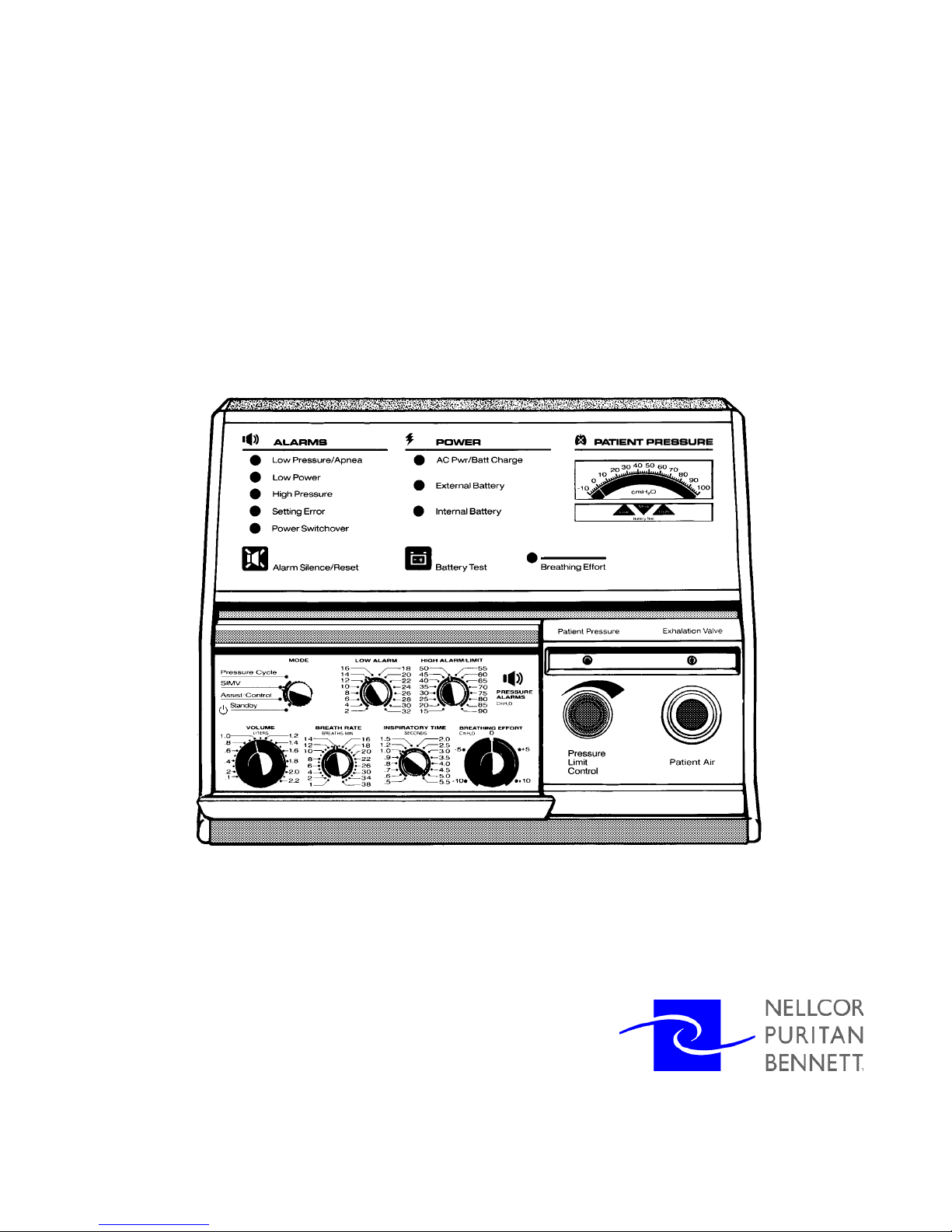
LP6 Plus, LP10, and LP20
Volume Ventilators
Technical Manual
L-004238-001 Rev. B
Page 2

LP6 Plus, LP10, and LP20 Technical Manual
For more information:
page ii
©Copyright 2000, Nellcor Puritan Bennett, Inc., 2800 Northwest Blvd., Minneapolis,
Minnesota 55441-2625 U.S.A. All rights reserved. No portion of this manual may be
copied, reproduced, or stored in any form without the express written permission of
Nellcor Puritan Bennett, Inc.
Nellcor Puritan Bennett is a registered trademark and A Breath of Fresh Air is a trademark of Nellcor Puritan Bennett, Inc.
For information on our full line of medical equipment and related services, contact Nellcor Puritan Bennett directly. General: (800) 497-4979. Customer Service: (800) 497-
4968. Technical Service: (800) 497-3787.
November 2000
Page 3

LP6 Plus, LP10, and LP20 Technical Manual
1 Introduction
1 Introduction
1 Introduction1 Introduction
Chapters
Chapters - - - - - - - - - - - - - - - - - - - - - - - - - - - - - - - - - - - - - -
Chapters Chapters
What’s New in this Revision
What’s New in this Revision - - - - - - - - - - - - - - - - - - - - - - - -
What’s New in this Revision What’s New in this Revision
Conventions
Conventions - - - - - - - - - - - - - - - - - - - - - - - - - - - - - - - - - - -
Conventions Conventions
2 Description
2 Description
2 Description2 Description
Components
Components - - - - - - - - - - - - - - - - - - - - - - - - - - - - - - - - - - -
ComponentsComponents
Front Panel (LP20 shown) - - - - - - - - - - - - - - - - - - - - - - - - - - - - 2-2
Back Panel (LP20 shown) - - - - - - - - - - - - - - - - - - - - - - - - - - - - 2-4
Operating Controls
Operating Controls - - - - - - - - - - - - - - - - - - - - - - - - - - - - - -
Operating Controls Operating Controls
Modes of Operation
Modes of Operation - - - - - - - - - - - - - - - - - - - - - - - - - - - - -
Modes of Operation Modes of Operation
Ventilator Parameters
Ventilator Parameters - - - - - - - - - - - - - - - - - - - - - - - - - - - -
Ventilator Parameters Ventilator Parameters
Accessories
Accessories - - - - - - - - - - - - - - - - - - - - - - - - - - - - - - - - - - - -
Accessories Accessories
Specifications
Specifications - - - - - - - - - - - - - - - - - - - - - - - - - - - - - - - - - -
Specifications Specifications
LP6 Plus, LP10, and LP20 Volume Ventilators - - - - - - - - - - - - - 2-12
Contents
- - - - - - - - - - - - - - - - - - - - - - - - - - - - - - - - - - - - - - 1-1
- - - - - - - - - - - - - - - - - - - - - - - - - - - - - - - - - - - - - - - - - - - - - - - - - - - - - - - - - - - - - - - - - - - - - - - - - - - -
- - - - - - - - - - - - - - - - - - - - - - - - 1-2
- - - - - - - - - - - - - - - - - - - - - - - - - - - - - - - - - - - - - - - - - - - - - - - -
- - - - - - - - - - - - - - - - - - - - - - - - - - - - - - - - - - - 1-2
- - - - - - - - - - - - - - - - - - - - - - - - - - - - - - - - - - - - - - - - - - - - - - - - - - - - - - - - - - - - - - - - - - - - - -
- - - - - - - - - - - - - - - - - - - - - - - - - - - - - - - - - - - 2-2
- - - - - - - - - - - - - - - - - - - - - - - - - - - - - - - - - - - - - - - - - - - - - - - - - - - - - - - - - - - - - - - - - - - - - -
- - - - - - - - - - - - - - - - - - - - - - - - - - - - - - 2-5
- - - - - - - - - - - - - - - - - - - - - - - - - - - - - - - - - - - - - - - - - - - - - - - - - - - - - - - - - - - -
- - - - - - - - - - - - - - - - - - - - - - - - - - - - - 2-6
- - - - - - - - - - - - - - - - - - - - - - - - - - - - - - - - - - - - - - - - - - - - - - - - - - - - - - - - - -
- - - - - - - - - - - - - - - - - - - - - - - - - - - - 2-8
- - - - - - - - - - - - - - - - - - - - - - - - - - - - - - - - - - - - - - - - - - - - - - - - - - - - - - - -
- - - - - - - - - - - - - - - - - - - - - - - - - - - - - - - - - - - - 2-11
- - - - - - - - - - - - - - - - - - - - - - - - - - - - - - - - - - - - - - - - - - - - - - - - - - - - - - - - - - - - - - - - - - - - - - - -
- - - - - - - - - - - - - - - - - - - - - - - - - - - - - - - - - - 2-12
- - - - - - - - - - - - - - - - - - - - - - - - - - - - - - - - - - - - - - - - - - - - - - - - - - - - - - - - - - - - - - - - - - - -
1-1
1-11-1
1-2
1-21-2
1-2
1-21-2
2-2
2-22-2
2-5
2-52-5
2-6
2-62-6
2-8
2-82-8
2-11
2-112-11
2-12
2-122-12
3 Testing
3 Testing
3 Testing3 Testing
Scope
Scope - - - - - - - - - - - - - - - - - - - - - - - - - - - - - - - - - - - - - - - -
Scope Scope
Equipment
Equipment - - - - - - - - - - - - - - - - - - - - - - - - - - - - - - - - - - - - -
Equipment Equipment
Supplies
Supplies - - - - - - - - - - - - - - - - - - - - - - - - - - - - - - - - - - - - - - -
Supplies Supplies
Procedure
Procedure - - - - - - - - - - - - - - - - - - - - - - - - - - - - - - - - - - - - -
Procedure Procedure
Operational Checklist
Operational Checklist - - - - - - - - - - - - - - - - - - - - - - - - - - - -
Operational Checklist Operational Checklist
Ventilator Operational Checklist
Ventilator Operational Checklist - - - - - - - - - - - - - - - - - - - -
Ventilator Operational Checklist Ventilator Operational Checklist
- - - - - - - - - - - - - - - - - - - - - - - - - - - - - - - - - - - - - - - - 3-2
- - - - - - - - - - - - - - - - - - - - - - - - - - - - - - - - - - - - - - - - - - - - - - - - - - - - - - - - - - - - - - - - - - - - - - - - - - - - - - - -
- - - - - - - - - - - - - - - - - - - - - - - - - - - - - - - - - - - - - 3-3
- - - - - - - - - - - - - - - - - - - - - - - - - - - - - - - - - - - - - - - - - - - - - - - - - - - - - - - - - - - - - - - - - - - - - - - - - -
- - - - - - - - - - - - - - - - - - - - - - - - - - - - - - - - - - - - - - - 3-3
- - - - - - - - - - - - - - - - - - - - - - - - - - - - - - - - - - - - - - - - - - - - - - - - - - - - - - - - - - - - - - - - - - - - - - - - - - - - - -
- - - - - - - - - - - - - - - - - - - - - - - - - - - - - - - - - - - - - 3-4
- - - - - - - - - - - - - - - - - - - - - - - - - - - - - - - - - - - - - - - - - - - - - - - - - - - - - - - - - - - - - - - - - - - - - - - - - -
Visual Inspection - - - - - - - - - - - - - - - - - - - - - - - - - - - - - - - - - - 3-4
Control Settings - - - - - - - - - - - - - - - - - - - - - - - - - - - - - - - - - - - 3-6
Connections - - - - - - - - - - - - - - - - - - - - - - - - - - - - - - - - - - - - - 3-6
Patient Circuit Leak Test - - - - - - - - - - - - - - - - - - - - - - - - - - - - - 3-7
Power Checkout - - - - - - - - - - - - - - - - - - - - - - - - - - - - - - - - - - 3-8
Assist/Control
SIMV Mode Checkout - - - - - - - - - - - - - - - - - - - - - - - - - - - - - - 3-11
Pressure Cycle Mode Checkout - - - - - - - - - - - - - - - - - - - - - - 3-13
Pressure Limit Checkout (LP10, LP20) - - - - - - - - - - - - - - - - - - - 3-14
Mode Checkout - - - - - - - - - - - - - - - - - - - - - - 3-9
- - - - - - - - - - - - - - - - - - - - - - - - - - - - 3-15
- - - - - - - - - - - - - - - - - - - - - - - - - - - - - - - - - - - - - - - - - - - - - - - - - - - - - - - -
- - - - - - - - - - - - - - - - - - - - 3-17
- - - - - - - - - - - - - - - - - - - - - - - - - - - - - - - - - - - - - - - -
3-2
3-23-2
3-3
3-33-3
3-3
3-33-3
3-4
3-43-4
3-15
3-153-15
3-17
3-173-17
November 2000
Page iii
Page iii
Page iiiPage iii
Page 4

4 Theory of Operation
4 Theory of Operation
4 Theory of Operation4 Theory of Operation
Pneumatic System Overview
Pneumatic System Overview - - - - - - - - - - - - - - - - - - - - - - -
Pneumatic System Overview Pneumatic System Overview
Mechanical System Overview
Mechanical System Overview - - - - - - - - - - - - - - - - - - - - - -
Mechanical System Overview Mechanical System Overview
Electrical System Overview
Electrical System Overview - - - - - - - - - - - - - - - - - - - - - - - -
Electrical System Overview Electrical System Overview
Operating Modes
Operating Modes - - - - - - - - - - - - - - - - - - - - - - - - - - - - - - -
Operating Modes Operating Modes
Boards and Major Components
Boards and Major Components - - - - - - - - - - - - - - - - - - - -
Boards and Major Components Boards and Major Components
Accessories
Accessories - - - - - - - - - - - - - - - - - - - - - - - - - - - - - - - - - - - -
Accessories Accessories
System Control
System Control - - - - - - - - - - - - - - - - - - - - - - - - - - - - - - - - - -
System Control System Control
Functional Block Diagram
Functional Block Diagram - - - - - - - - - - - - - - - - - - - - - - - - -
Functional Block Diagram Functional Block Diagram
LP6 Plus, LP10, and LP20 Technical Manual
- - - - - - - - - - - - - - - - - - - - - - - 4-2
- - - - - - - - - - - - - - - - - - - - - - - - - - - - - - - - - - - - - - - - - - - - - -
- - - - - - - - - - - - - - - - - - - - - - 4-3
- - - - - - - - - - - - - - - - - - - - - - - - - - - - - - - - - - - - - - - - - - - -
- - - - - - - - - - - - - - - - - - - - - - - - 4-4
- - - - - - - - - - - - - - - - - - - - - - - - - - - - - - - - - - - - - - - - - - - - - - - -
- - - - - - - - - - - - - - - - - - - - - - - - - - - - - - - 4-5
- - - - - - - - - - - - - - - - - - - - - - - - - - - - - - - - - - - - - - - - - - - - - - - - - - - - - - - - - - - - - -
Standby - - - - - - - - - - - - - - - - - - - - - - - - - - - - - - - - - - - - - - - - - 4-5
Assist/Control - - - - - - - - - - - - - - - - - - - - - - - - - - - - - - - - - - - - - 4-5
SIMV - - - - - - - - - - - - - - - - - - - - - - - - - - - - - - - - - - - - - - - - - - - - 4-6
Pressure Cycle - - - - - - - - - - - - - - - - - - - - - - - - - - - - - - - - - - - - 4-7
- - - - - - - - - - - - - - - - - - - - 4-7
- - - - - - - - - - - - - - - - - - - - - - - - - - - - - - - - - - - - - - - -
Logic Board - - - - - - - - - - - - - - - - - - - - - - - - - - - - - - - - - - - - - - 4-7
Power/Motor Board - - - - - - - - - - - - - - - - - - - - - - - - - - - - - - - - 4-7
LED Board - - - - - - - - - - - - - - - - - - - - - - - - - - - - - - - - - - - - - - - 4-7
Exhalation Solenoid Valve - - - - - - - - - - - - - - - - - - - - - - - - - - - 4-7
Pressure Transducer - - - - - - - - - - - - - - - - - - - - - - - - - - - - - - - - 4-7
Fan - - - - - - - - - - - - - - - - - - - - - - - - - - - - - - - - - - - - - - - - - - - - - 4-7
Audio Alarm - - - - - - - - - - - - - - - - - - - - - - - - - - - - - - - - - - - - - - 4-8
Magnetic Position Sensor - - - - - - - - - - - - - - - - - - - - - - - - - - - - 4-8
Motor and Gearbox - - - - - - - - - - - - - - - - - - - - - - - - - - - - - - - 4-8
Transformer - - - - - - - - - - - - - - - - - - - - - - - - - - - - - - - - - - - - - - 4-8
RFI Filter - - - - - - - - - - - - - - - - - - - - - - - - - - - - - - - - - - - - - - - - - 4-8
AC Power Switch/Circuit Breaker - - - - - - - - - - - - - - - - - - - - - - 4-8
Rectifier - - - - - - - - - - - - - - - - - - - - - - - - - - - - - - - - - - - - - - - - - 4-8
AC Power Cord - - - - - - - - - - - - - - - - - - - - - - - - - - - - - - - - - - - 4-8
Internal Battery - - - - - - - - - - - - - - - - - - - - - - - - - - - - - - - - - - - 4-8
DC Circuit Breaker - - - - - - - - - - - - - - - - - - - - - - - - - - - - - - - - - 4-8
Nurse Call Board (LP20 only) - - - - - - - - - - - - - - - - - - - - - - - - - 4-8
- - - - - - - - - - - - - - - - - - - - - - - - - - - - - - - - - - - - 4-9
- - - - - - - - - - - - - - - - - - - - - - - - - - - - - - - - - - - - - - - - - - - - - - - - - - - - - - - - - - - - - - - - - - - - - - - -
Printer - - - - - - - - - - - - - - - - - - - - - - - - - - - - - - - - - - - - - - - - - - - 4-9
External Battery - - - - - - - - - - - - - - - - - - - - - - - - - - - - - - - - - - - 4-9
- - - - - - - - - - - - - - - - - - - - - - - - - - - - - - - - - - 4-10
- - - - - - - - - - - - - - - - - - - - - - - - - - - - - - - - - - - - - - - - - - - - - - - - - - - - - - - - - - - - - - - - - - - -
Microprocessor - - - - - - - - - - - - - - - - - - - - - - - - - - - - - - - - - - - 4-10
Analog to Digital Converter - - - - - - - - - - - - - - - - - - - - - - - - - - 4-11
Digital to Analog Converter - - - - - - - - - - - - - - - - - - - - - - - - - - 4-11
Chip Identification - - - - - - - - - - - - - - - - - - - - - - - - - - - - - - - - - 4-12
High/Low Pressure Alarms - - - - - - - - - - - - - - - - - - - - - - - - - - - 4-12
Alarm Lights; Front Panel Push Buttons - - - - - - - - - - - - - - - - - - 4-13
Error Detection - - - - - - - - - - - - - - - - - - - - - - - - - - - - - - - - - - - - 4-13
Power/Motor Board - - - - - - - - - - - - - - - - - - - - - - - - - - - - - - - - 4-13
- - - - - - - - - - - - - - - - - - - - - - - - - 4-16
- - - - - - - - - - - - - - - - - - - - - - - - - - - - - - - - - - - - - - - - - - - - - - - - - -
4-2
4-24-2
4-3
4-34-3
4-4
4-44-4
4-5
4-54-5
4-7
4-74-7
4-9
4-94-9
4-10
4-104-10
4-16
4-164-16
Page iv
Page iv
Page ivPage iv
November 2000
Page 5

LP6 Plus, LP10, and LP20 Technical Manual
5 Maintenance
5 Maintenance
5 Maintenance5 Maintenance
Maintenance Schedule
Maintenance Schedule - - - - - - - - - - - - - - - - - - - - - - - - - -
Maintenance Schedule Maintenance Schedule
Preventive Maintenance
Preventive Maintenance - - - - - - - - - - - - - - - - - - - - - - - - - -
Preventive Maintenance Preventive Maintenance
Visual Check - - - - - - - - - - - - - - - - - - - - - - - - - - - - - - - - - - - - - 5-2
Exterior cleaning - - - - - - - - - - - - - - - - - - - - - - - - - - - - - - - - - - 5-2
Inlet Filter
Bacteria Filter - - - - - - - - - - - - - - - - - - - - - - - - - - - - - - - - - - - - - 5-4
Patient Circuit - - - - - - - - - - - - - - - - - - - - - - - - - - - - - - - - - - - - 5-6
Exhalation Manifold Assembly - - - - - - - - - - - - - - - - - - - - - - - - 5-7
Humidifier - - - - - - - - - - - - - - - - - - - - - - - - - - - - - - - - - - - - - - - - 5-7
External Battery - - - - - - - - - - - - - - - - - - - - - - - - - - - - - - - - - - - 5-8
Printer Module - - - - - - - - - - - - - - - - - - - - - - - - - - - - - - - - - - - - 5-9
6 Troubleshooting
6 Troubleshooting
6 Troubleshooting6 Troubleshooting
Troubleshooting Chart
Troubleshooting Chart - - - - - - - - - - - - - - - - - - - - - - - - - - - -
Troubleshooting Chart Troubleshooting Chart
Alarm Condition Chart
Alarm Condition Chart - - - - - - - - - - - - - - - - - - - - - - - - - - -
Alarm Condition Chart Alarm Condition Chart
- - - - - - - - - - - - - - - - - - - - - - - - - - 5-1
- - - - - - - - - - - - - - - - - - - - - - - - - - - - - - - - - - - - - - - - - - - - - - - - - - - -
- - - - - - - - - - - - - - - - - - - - - - - - - - 5-2
- - - - - - - - - - - - - - - - - - - - - - - - - - - - - - - - - - - - - - - - - - - - - - - - - - - -
- - - - - - - - - - - - - - - - - - - - - - - - - - - - - - - - - - - - - - - 5-3
- - - - - - - - - - - - - - - - - - - - - - - - - - - - 6-1
- - - - - - - - - - - - - - - - - - - - - - - - - - - - - - - - - - - - - - - - - - - - - - - - - - - - - - - -
- - - - - - - - - - - - - - - - - - - - - - - - - - - 6-4
- - - - - - - - - - - - - - - - - - - - - - - - - - - - - - - - - - - - - - - - - - - - - - - - - - - - - -
5-1
5-15-1
5-2
5-25-2
6-1
6-16-1
6-4
6-46-4
7 Schematics
7 Schematics
7 Schematics7 Schematics
Final Assembly
Final Assembly - - - - - - - - - - - - - - - - - - - - - - - - - - - - - - - - - -
Final Assembly Final Assembly
Front Panel (LP6 Plus, LP10)
Front Panel (LP6 Plus, LP10) - - - - - - - - - - - - - - - - - - - - - - - -
Front Panel (LP6 Plus, LP10) Front Panel (LP6 Plus, LP10)
Front Panel (LP6 Plus/LP10)
Front Panel (LP6 Plus/LP10) - - - - - - - - - - - - - - - - - - - - - - - - -
Front Panel (LP6 Plus/LP10) Front Panel (LP6 Plus/LP10)
Front Panel (LP20)
Front Panel (LP20) - - - - - - - - - - - - - - - - - - - - - - - - - - - - - - -
Front Panel (LP20) Front Panel (LP20)
Front Panel (LP20)
Front Panel (LP20) - - - - - - - - - - - - - - - - - - - - - - - - - - - - - - -
Front Panel (LP20) Front Panel (LP20)
Through-Hole Logic Board
Through-Hole Logic Board - - - - - - - - - - - - - - - - - - - - - - - - -
Through-Hole Logic Board Through-Hole Logic Board
Through-Hole Logic Board
Through-Hole Logic Board - - - - - - - - - - - - - - - - - - - - - - - - -
Through-Hole Logic Board Through-Hole Logic Board
Through-Hole Logic Board
Through-Hole Logic Board - - - - - - - - - - - - - - - - - - - - - - - - -
Through-Hole Logic Board Through-Hole Logic Board
Through-Hole Logic Board
Through-Hole Logic Board - - - - - - - - - - - - - - - - - - - - - - - - -
Through-Hole Logic Board Through-Hole Logic Board
Surface-Mount Logic Board
Surface-Mount Logic Board - - - - - - - - - - - - - - - - - - - - - - - -
Surface-Mount Logic Board Surface-Mount Logic Board
Surface-Mount Logic Board
Surface-Mount Logic Board - - - - - - - - - - - - - - - - - - - - - - - -
Surface-Mount Logic Board Surface-Mount Logic Board
Surface-Mount Logic Board
Surface-Mount Logic Board - - - - - - - - - - - - - - - - - - - - - - - -
Surface-Mount Logic Board Surface-Mount Logic Board
Surface-Mount Logic Board
Surface-Mount Logic Board - - - - - - - - - - - - - - - - - - - - - - - -
Surface-Mount Logic Board Surface-Mount Logic Board
Through-Hole Power-Motor Board
Through-Hole Power-Motor Board - - - - - - - - - - - - - - - - - - -
Through-Hole Power-Motor Board Through-Hole Power-Motor Board
Through-Hole Power/Motor Board
Through-Hole Power/Motor Board - - - - - - - - - - - - - - - - - - -
Through-Hole Power/Motor Board Through-Hole Power/Motor Board
Through-Hole Power/Motor Board
Through-Hole Power/Motor Board - - - - - - - - - - - - - - - - - - -
Through-Hole Power/Motor Board Through-Hole Power/Motor Board
Surface-Mount Power/Motor Board
Surface-Mount Power/Motor Board - - - - - - - - - - - - - - - - - -
Surface-Mount Power/Motor Board Surface-Mount Power/Motor Board
Surface-Mount Power/Motor Board
Surface-Mount Power/Motor Board - - - - - - - - - - - - - - - - - -
Surface-Mount Power/Motor Board Surface-Mount Power/Motor Board
Surface-Mount Power/Motor Board
Surface-Mount Power/Motor Board - - - - - - - - - - - - - - - - - -
Surface-Mount Power/Motor Board Surface-Mount Power/Motor Board
Pressure Limit Assembly (LP10, LP20)
Pressure Limit Assembly (LP10, LP20) - - - - - - - - - - - - - - - - - -
Pressure Limit Assembly (LP10, LP20) Pressure Limit Assembly (LP10, LP20)
- - - - - - - - - - - - - - - - - - - - - - - - - - - - - - - - - - 7-2
- - - - - - - - - - - - - - - - - - - - - - - - - - - - - - - - - - - - - - - - - - - - - - - - - - - - - - - - - - - - - - - - - - - -
- - - - - - - - - - - - - - - - - - - - - - - - 7-3
- - - - - - - - - - - - - - - - - - - - - - - - - - - - - - - - - - - - - - - - - - - - - - - -
- - - - - - - - - - - - - - - - - - - - - - - - - 7-4
- - - - - - - - - - - - - - - - - - - - - - - - - - - - - - - - - - - - - - - - - - - - - - - - - -
- - - - - - - - - - - - - - - - - - - - - - - - - - - - - - - 7-5
- - - - - - - - - - - - - - - - - - - - - - - - - - - - - - - - - - - - - - - - - - - - - - - - - - - - - - - - - - - - - -
- - - - - - - - - - - - - - - - - - - - - - - - - - - - - - - 7-6
- - - - - - - - - - - - - - - - - - - - - - - - - - - - - - - - - - - - - - - - - - - - - - - - - - - - - - - - - - - - - -
- - - - - - - - - - - - - - - - - - - - - - - - - 7-7
- - - - - - - - - - - - - - - - - - - - - - - - - - - - - - - - - - - - - - - - - - - - - - - - - -
- - - - - - - - - - - - - - - - - - - - - - - - - 7-8
- - - - - - - - - - - - - - - - - - - - - - - - - - - - - - - - - - - - - - - - - - - - - - - - - -
- - - - - - - - - - - - - - - - - - - - - - - - - 7-9
- - - - - - - - - - - - - - - - - - - - - - - - - - - - - - - - - - - - - - - - - - - - - - - - - -
- - - - - - - - - - - - - - - - - - - - - - - - - 7-10
- - - - - - - - - - - - - - - - - - - - - - - - - - - - - - - - - - - - - - - - - - - - - - - - - -
- - - - - - - - - - - - - - - - - - - - - - - - 7-11
- - - - - - - - - - - - - - - - - - - - - - - - - - - - - - - - - - - - - - - - - - - - - - - -
- - - - - - - - - - - - - - - - - - - - - - - - 7-12
- - - - - - - - - - - - - - - - - - - - - - - - - - - - - - - - - - - - - - - - - - - - - - - -
- - - - - - - - - - - - - - - - - - - - - - - - 7-13
- - - - - - - - - - - - - - - - - - - - - - - - - - - - - - - - - - - - - - - - - - - - - - - -
- - - - - - - - - - - - - - - - - - - - - - - - 7-14
- - - - - - - - - - - - - - - - - - - - - - - - - - - - - - - - - - - - - - - - - - - - - - - -
- - - - - - - - - - - - - - - - - - - 7-15
- - - - - - - - - - - - - - - - - - - - - - - - - - - - - - - - - - - - - -
- - - - - - - - - - - - - - - - - - - 7-16
- - - - - - - - - - - - - - - - - - - - - - - - - - - - - - - - - - - - - -
- - - - - - - - - - - - - - - - - - - 7-17
- - - - - - - - - - - - - - - - - - - - - - - - - - - - - - - - - - - - - -
- - - - - - - - - - - - - - - - - - 7-18
- - - - - - - - - - - - - - - - - - - - - - - - - - - - - - - - - - - -
- - - - - - - - - - - - - - - - - - 7-19
- - - - - - - - - - - - - - - - - - - - - - - - - - - - - - - - - - - -
- - - - - - - - - - - - - - - - - - 7-20
- - - - - - - - - - - - - - - - - - - - - - - - - - - - - - - - - - - -
- - - - - - - - - - - - - - - - - - 7-21
- - - - - - - - - - - - - - - - - - - - - - - - - - - - - - - - - - - -
7-2
7-27-2
7-3
7-37-3
7-4
7-47-4
7-5
7-57-5
7-6
7-67-6
7-7
7-77-7
7-8
7-87-8
7-9
7-97-9
7-10
7-107-10
7-11
7-117-11
7-12
7-127-12
7-13
7-137-13
7-14
7-147-14
7-15
7-157-15
7-16
7-167-16
7-17
7-177-17
7-18
7-187-18
7-19
7-197-19
7-20
7-207-20
7-21
7-217-21
November 2000
Page v
Page v
Page vPage v
Page 6

8 Service Policy
8 Service Policy
8 Service Policy8 Service Policy
LP6 Plus, LP10, and LP20 Technical Manual
Front Bezel (LP6 Plus only)
Front Bezel (LP6 Plus only) - - - - - - - - - - - - - - - - - - - - - - - - -
Front Bezel (LP6 Plus only) Front Bezel (LP6 Plus only)
Right End Assembly
Right End Assembly - - - - - - - - - - - - - - - - - - - - - - - - - - - - - -
Right End Assembly Right End Assembly
Back Panel (LP6 Plus, LP10)
Back Panel (LP6 Plus, LP10) - - - - - - - - - - - - - - - - - - - - - - - -
Back Panel (LP6 Plus, LP10) Back Panel (LP6 Plus, LP10)
Back Panel (LP6 Plus, LP10)
Back Panel (LP6 Plus, LP10) - - - - - - - - - - - - - - - - - - - - - - - -
Back Panel (LP6 Plus, LP10) Back Panel (LP6 Plus, LP10)
Back Panel (LP20)
Back Panel (LP20) - - - - - - - - - - - - - - - - - - - - - - - - - - - - - - -
Back Panel (LP20) Back Panel (LP20)
Back Panel (LP20)
Back Panel (LP20) - - - - - - - - - - - - - - - - - - - - - - - - - - - - - - -
Back Panel (LP20) Back Panel (LP20)
Nurse Call Board
Nurse Call Board - - - - - - - - - - - - - - - - - - - - - - - - - - - - - - - -
Nurse Call Board Nurse Call Board
Limited Warranty
Limited Warranty - - - - - - - - - - - - - - - - - - - - - - - - - - - - - - - -
Limited Warranty Limited Warranty
- - - - - - - - - - - - - - - - - - - - - - - - - - - - - - 7-23
- - - - - - - - - - - - - - - - - - - - - - - - - - - - - - - - - - - - - - - - - - - - - - - - - - - - - - - - - - - -
- - - - - - - - - - - - - - - - - - - - - - - - - - - - - - - 7-26
- - - - - - - - - - - - - - - - - - - - - - - - - - - - - - - - - - - - - - - - - - - - - - - - - - - - - - - - - - - - - -
- - - - - - - - - - - - - - - - - - - - - - - - - - - - - - - 7-27
- - - - - - - - - - - - - - - - - - - - - - - - - - - - - - - - - - - - - - - - - - - - - - - - - - - - - - - - - - - - - -
- - - - - - - - - - - - - - - - - - - - - - - - - - - - - - - - 7-28
- - - - - - - - - - - - - - - - - - - - - - - - - - - - - - - - - - - - - - - - - - - - - - - - - - - - - - - - - - - - - - - -
- - - - - - - - - - - - - - - - - - - - - - - - - - - - - - - - 8-2
- - - - - - - - - - - - - - - - - - - - - - - - - - - - - - - - - - - - - - - - - - - - - - - - - - - - - - - - - - - - - - - -
- - - - - - - - - - - - - - - - - - - - - - - - - 7-22
- - - - - - - - - - - - - - - - - - - - - - - - - - - - - - - - - - - - - - - - - - - - - - - - - -
- - - - - - - - - - - - - - - - - - - - - - - - 7-24
- - - - - - - - - - - - - - - - - - - - - - - - - - - - - - - - - - - - - - - - - - - - - - - -
- - - - - - - - - - - - - - - - - - - - - - - - 7-25
- - - - - - - - - - - - - - - - - - - - - - - - - - - - - - - - - - - - - - - - - - - - - - - -
7-22
7-227-22
7-23
7-237-23
7-24
7-247-24
7-25
7-257-25
7-26
7-267-26
7-27
7-277-27
7-28
7-287-28
8-2
8-28-2
Page vi
Page vi
Page viPage vi
November 2000
Page 7

1 Introduction
1 Introduction
1 Introduction1 Introduction
This Technical Manual provides procedures to verify and maintain the
LP6 Plus, LP10, and LP20 Volume Ventilators. It is not intended to be a
complete maintenance document and therefore contains no disassembly, repair, or reassembly instructions.
Refer any adjustments or procedures that exceed the scope of this manual to a Nellcor Puritan Bennett Technical Service Representative by
calling:
This manual contains proprietary information. It is intended for use
only by qualified individuals in the installation and maintenance of the
LP6 Plus, LP10, and LP20 Ventilators. Receipt, purchase, or possession
of this document in no way confers or transfers any other rights for the
use of this information. Disclosure or reproduction of the enclosed,
without the written permission of Nellcor Puritan Bennett, Inc., is prohibited.
Chapters
Chapters
ChaptersChapters
800-497-3787
Theory of Operation
November 2000
Description
Testing
Maintenance
This manual consists of the following chapters:
Identifies all features and functions of the ventilators.
Provides procedures for verifying unit operation.
A detailed overview of the ventilators, with a block diagram to supplement the text.
Outlines preventive maintenance procedures and troubleshooting.
Page 1-1
Page 1-1
Page 1-1Page 1-1
Page 8

What’s New in this Revision
What’s New in this Revision
What’s New in this RevisionWhat’s New in this Revision
What’s New in this Revision
What’s New in this Revision
What’s New in this RevisionWhat’s New in this Revision
LP6 Plus, LP10, and LP20 Technical Manual
Chapter 3 Testing
Chapter 4 Theory of Operation
Chapter 5 Maintenance
Chapter 7 Schematics
Conventions
Conventions
ConventionsConventions
Patient Circuit Leak has been updated.
Surface-mount logic and power/motor boards are being used in
addition to through-hole boards. Details are given for all board
types.
Newer production units have an internal battery charge voltage of
14.4V.
New procedure has been added for inspecting and replacing the
Flatpak inlet filter.
Part descriptions added to drawings.
New surface-mount board drawings added.
Back panel drawing updated with new grounding scheme.
Page 1-2
Page 1-2
Page 1-2Page 1-2
Note
Caution
Caution
CautionCaution
Warning
Warning
WarningWarning
The following differentiation is made in this manual between Notes,
Cautions,
Directions that make it easier to use or service the product.
Directions that help avoid damaging the ventilators.
Directions that warn of conditions or actions that put the
Directions that warn of conditions or actions that put the
Directions that warn of conditions or actions that put theDirections that warn of conditions or actions that put the
patient, the technician, or other people at risk of injury.
patient, the technician, or other people at risk of injury.
patient, the technician, or other people at risk of injury.patient, the technician, or other people at risk of injury.
, and War n i ngs::::
, ,
November 2000
Page 9

2 Description
2 Description
2 Description2 Description
The Nellcor Puritan Bennett LP6 Plus, LP10, and LP20 are microprocessor-controlled Volume Ventilators. They provide continuous respiratory
support for patients encountering ventilatory insufficiencies in home or
hospital settings, or in transport.
The ventilators offer a range of delivery volumes, inspiratory times, and
breathing rates. The control knobs in the recessed front panel allow the
physician or respiratory therapist to set the parameters that will provide
appropriate ventilation. The door panel and knobs are designed to prevent tampering and accidental setting changes.
The ventilators provide both audible and visual alarms. See the Trouble-
shooting section for a complete list of alarms, indications, and possible
causes.
November 2000
Page 2-1
Page 2-1
Page 2-1Page 2-1
Page 10
Components
Components
ComponentsComponents
Components
Components
ComponentsComponents
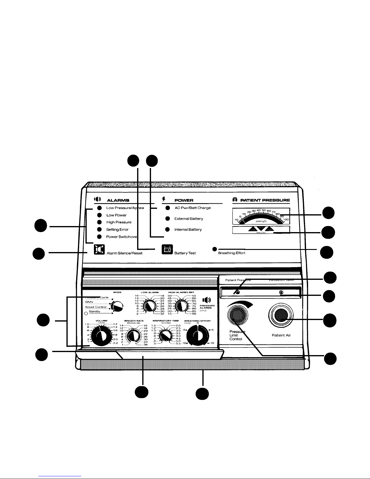
Front Panel (LP20 shown)
Front Panel (LP20 shown)
Front Panel (LP20 shown)Front Panel (LP20 shown)
LP6 Plus, LP10, and LP20 Technical Manual
b
c
d
e
a
o
n
m
l
k
j
f
Page 2-2
Page 2-2
Page 2-2Page 2-2
i
g
h
November 2000
Page 11

LP6 Plus, LP10, and LP20 Technical Manual
Components
Components
ComponentsComponents
a
Power Source Indicators
on when AC power is in use and either battery is
charging. Solid Amber Light is on when an external battery is providing power. Flashing Amber
Light is on and audio signal every five minutes
when internal battery is in use.
Green Light is
b
Battery Test
external/internal battery charge level (the ventilator must be operating on the battery being
tested). Read results on Battery Condition scale
of the
with
machine. Read results on
and multiply the number indicated on the meter
by 200.
PATIENT PRESSURE
ALARM SILENCE/RESE
Press this button for a test of
meter. Press in combination
for operating hours on
T
meter
PATIENT PRESSURE
c
These LEDs
Visual Alarm Indicators
identify alarm conditions or alarm pre-silence.
d
ALARM SILENCE/RESET
test alarms (on the LP20, hold for 3 seconds).
Push to pre-silence alarms for 60 seconds (LP20
only). Push to silence any audible alarm (except
setting error or apnea alarms) for 60 seconds. A
silenced alarm will automatically reset when the
condition is corrected.
Button Push to
h
Front Carrying Handle
i
Pressure Limit Control (LP10, LP20)
control limits the patient pressure during an
assisted or controlled breath. The pressure limit
control knob has a locking outer ring; push the
outer ring in and turn the small center knob to
change settings.
This
j
PATIENT AIR Port
nection for patient air tube.
Standard 22 mm con-
k
EXHALATION VALVE Port
for the exhalation valve tubing of the patient circuit.
l
PATIENT PRESSURE Port
the proximal pressure line of the patient circuit.
Connection and line are color coded with black
stripe.
A connection
A connection for
m
BREATHING EFFORT
vated by patient breathing effort. Breathing effort
sensitivity is set by the
knob.
Green light is acti-
BREATHING EFFORT
control
e
Ventilator Control Knobs
Controls" on page 2-5 for details.
BREATHING EFFORT
knobs; push in and turn to change setting.
controls are locking, skirted
f
Alarm Reference Guide
alarm functions with suggestions for corrective
action.
g
Control Panel Door
to protect controls.
November 2000
Magnetically latched
See "Operating
VOLUM E
Summary of
and
n
Battery Condition Scale
the
BATTERY TEST
here.
button, read the battery condition
While pressing
o
PATIENT PRESSURE
mal pressure. Also displays battery charge level
and machine hours of operation when appropriate buttons are pressed.
Meter Displays proxi-
Page 2-3
Page 2-3
Page 2-3Page 2-3
Page 12
Components
Components
ComponentsComponents
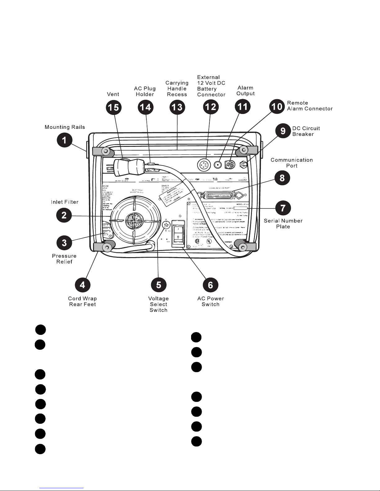
Back Panel (LP20 shown)
Back Panel (LP20 shown)
Back Panel (LP20 shown) Back Panel (LP20 shown)
LP6 Plus, LP10, and LP20 Technical Manual
1
Mounting Rails
2
INLET FILTER with Screw Off Cap
is drawn through this filter. Protects airflow
and allows for easy filter change.
3
Pressure Relief
4
Cord Wrap and Rear Feet
5
Voltage Select Switch
6
AC Power Switch/Circuit Breaker
7
Serial Number Plate
8
COMMUNICATIONS PORT
Page 2-4
Page 2-4
Page 2-4Page 2-4
Connection for accessories.
Patient air
Do not block.
Connector for
optional printer.
9
DC Circuit Breaker
10
REMOTE ALARM Connection
11
ALARM OUTPUT (LP20 only)
jack for connecting the ventilator to a nurse
call station.
12
EXTERNAL 12VDC BATTERY Connector
13
Rear Carrying Handle Recess
14
AC Plug Holder
15
Vent
Do not block.
1/4" phone
November 2000
Page 13
LP6 Plus, LP10, and LP20 Technical Manual
Operating Controls
Operating Controls
Operating ControlsOperating Controls
War ning
War ning
War ningWar ning
Operating Controls
Operating Controls
Operating ControlsOperating Controls
Periodically check the control panel to be sure that the
Periodically check the control panel to be sure that the
Periodically check the control panel to be sure that thePeriodically check the control panel to be sure that the
controls are on the prescribed settings. The settings should
controls are on the prescribed settings. The settings should
controls are on the prescribed settings. The settings shouldcontrols are on the prescribed settings. The settings should
not be changed without the order of a physician.
not be changed without the order of a physician.
not be changed without the order of a physician.not be changed without the order of a physician.
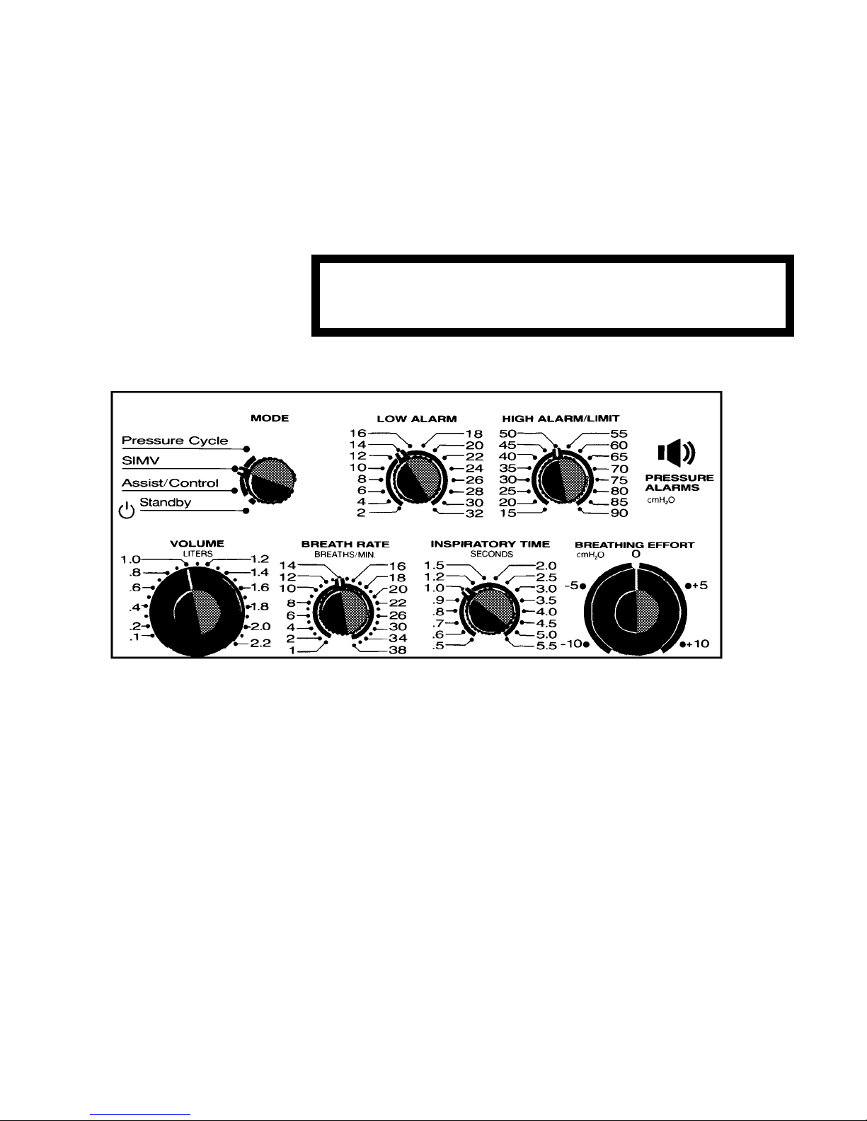
MODE Control:
See page 2-6.
VOLUME Control:
Push in, then turn the knob to change the setting. When adjusted, the volume changes in
100 ml steps during each breath until the new
volume is reached.
BREATH RATE Control:
breaths per minute.
INSPIRATORY TIME Control: A
time for the breath.
November 2000
Selects modes of operation.
Sets the breath volume.
Adjusts the number of
djusts delivery
BREATHING EFFORT Control:
patient effort needed to trigger a machine delivered breath. Push in, then turn to change the
When a breath is sensed, the
setting.
ING EFFORT
LOW ALARM:
low pressure alarm sounds if this limit is not
reached for two consecutive breaths.
HIGH ALARM/LIMIT:
alarm or high pressure limit. The high pressure alarm sounds when the setting is
exceeded (except in Pressure Limited mode).
The alarm stops when the pressure drops to a
lower level. Inspiration ends when the set point
is reached.
indicator
lights.
Sets the low pressure limit. The
Sets the high pressure
Adjusts the
BREATH-
Page 2-5
Page 2-5
Page 2-5Page 2-5
Page 14

Modes of Operation
Modes of Operation
Modes of OperationModes of Operation
Modes of Operation
Modes of Operation
Modes of OperationModes of Operation
LP6 Plus, LP10, and LP20 Technical Manual
Standby
Standby I
StandbyStandby
Note
Assist/Control
Assist/Control
Assist/ControlAssist/Control
Modes are set by a 4-position
lows:
• Standby
• Assist/Control
• SIMV
• Pressure Cycle
n this mode, the ventilator is placed in a Standby mode, while both
the external or internal batteries are being recharged. AC power
must be on. Patient assisted ventilation cannot occur in this mode,
but spontaneous breathing through the machine can occur.
Batteries charge equally well in all
The ventilator functions as an assistant or controller, depending
upon the patient inspiratory efforts. The Assist mode permits the
patient to receive patient-initiated breaths, delivered when the
patients inspiratory effort creates a negative pressure that equals or
exceeds that set on the
If the patient fails to breathe spontaneously or to achieve the
required negative pressure, the ventilator takes control and delivers
a breath to the patient. The ventilator continues to function as a
controller until the patient resumes spontaneous inspiratory efforts
at an acceptable rate and depth (negative pressure).
BREATHING EFFORT
switch. The modes are as fol-
MODE
switch positions.
MODE
control
.
SIMV
SIMV
SIMVSIMV
Page 2-6
Page 2-6
Page 2-6Page 2-6
If the breathing rate is set at less than 6 BPM and the patient makes
no spontaneous effort, the apnea alarm sounds within 10 seconds;
the ventilator then delivers 10 BPM at the preset volume.
The SIMV (Synchronized Intermittent Mandatory Ventilation) mode
permits patients to breathe spontaneously between mandatory
machine-delivered breaths. This mode is frequently used where
sleep apnea may occur, to assist patients with advanced COPD, or
to wean patients from mechanical ventilation.
Under normal SIMV operation, the ventilator delivers mandatory
breaths at a rate set on the
tors the patients spontaneous breathing and synchronizes these
mandatory breaths to improve patient comfort.
BREATH RATE
control. The ventilator moni-
November 2000
Page 15

LP6 Plus, LP10, and LP20 Technical Manual
Pressure Cycle
Pressure Cycle T
Pressure CyclePressure Cycle
Modes of Operation
Modes of Operation
Modes of OperationModes of Operation
If the patients inspiratory efforts stop, the following occurs:
• For preset SIMV rates between 1 and 5 BPM, an apnea alarm
sounds after 20 seconds, and the ventilator delivers 10 BPM at
the set volume.
• At rates of 6 BPM or greater, the ventilator will continue to
deliver mandatory breaths at the set rate and volume; the apnea
alarm will not sound.
his mode is similar to the Assist/Control mode with the exception
that the
HIGH ALARM/LIMIT
cutoff. Therefore, if the pressure limit set on the
(pressure) control determines inspiratory
con-
HIGH ALARM/LIMIT
trol is reached before the set inspiratory volume is delivered, this
pressure limit terminates inspiration, regardless of volume delivered, and no alarm sounds. The high pressure limit may be selected
from 15 to 90 cmH
O above atmospheric pressure. If the termina-
2
tion is ineffective, causing the pressure to exceed the high pressure
limit setting by more than 10 cmH
O, the
2
HIGH PRESSURE
light and
audio alarm activate.
If the patient makes no effort to breathe, the ventilator will take control and deliver air. Exactly how this occurs depends on the
setting:
RATE
With
BREATH RATE
set at 1-5 BPM: If the patient does not start a breath
BREATH
for 10 seconds, an apnea alarm signals the caregiver; the ventilator
delivers 10 breaths per minute at the set volume, or until it reaches
the set pressure limit.
With
BREATH RATE
set at 6 BPM or greater: The ventilator will continue
to deliver breaths at the set rate. The apnea alarm will not sound
unless the ventilator cannot deliver a breath.
November 2000
Page 2-7
Page 2-7
Page 2-7Page 2-7
Page 16

Ventilator Parameters
Ventilator Parameters
Ventilator ParametersVentilator Parameters
Ventilator Parameters
Ventilator Parameters
Ventilator ParametersVentilator Parameters
Vo lu m e
Vo lu m e
Vo lu m eVo lu m e
Breath Rate
Breath Rate
Breath RateBreath Rate
Inspiratory or I-Time
Inspiratory or I-Time
Inspiratory or I-TimeInspiratory or I-Time
The delivered volume, or tidal volume, is set using the front panel
VOLUM E
with continuous settings ranging from 100 to 2200 ml.
Breathing rates (breaths per minute) are adjustable using the
RATE
of 1 BPM), and 22 to 38 BPM (in increments of 2 BPM).
The
into the patients lungs, thereby varying the amount of time that is
required to deliver the set volume. Inspiratory time settings range
from 0.5 to 1.0 sec. (in increments of 0.1 sec.), and 1.5 to 5.5 seconds (in increments of 0.5 sec.). Expiratory time and the I/E ratio
are determined by the
rate is determined by the
LP6 Plus, LP10, and LP20 Technical Manual
control. This push-to-turn control sets piston excursion,
BREATH
control. The control permits rates of 1 to 20 BPM (in increments
control adjusts the rate of air flow being delivered
INSPIRATORY TIME
INSPIRATORY TIME
VOL UME
and
and
INSPIRATORY TIME
BREATH RATE
settings.
settings; flow
Note
Breathing Effort
Breathing Effort
Breathing EffortBreathing Effort
Warning
Warning
Warning Warning
BREATH RATE
and
INSPIRATORY TIME
inspiratory time longer than expiratory time will cause a
alarm. The ventilator will deliver at the set inspiratory
ERROR
settings that would result in
SETTING
time at an I/E ratio of 1:1.
The
BREATHING EFFORT
effort necessary for triggering a machine-delivered breath, or to
reset the apnea alarm (at breathing rates of 1 - 5 BPM). Settings are
continuous from -10 to +10 cmH
pressure. When a sufficient breathing effort is sensed, the green
BREATHING EFFORT
used to compensate for Positive End Expiratory Pressure (PEEP).
BREATHING EFFORT
may cause the ventilator to autocycle (come on and off
may cause the ventilator to autocycle (come on and off
may cause the ventilator to autocycle (come on and offmay cause the ventilator to autocycle (come on and off
repeatedly without patient effort).
repeatedly without patient effort).
repeatedly without patient effort). repeatedly without patient effort).
control allows the operator to set the patient
O, with zero being atmospheric
2
indicator lights. Control settings above zero (+) are
settings above zero without the use of PEEP
settings above zero without the use of PEEP
settings above zero without the use of PEEPsettings above zero without the use of PEEP
Page 2-8
Page 2-8
Page 2-8Page 2-8
November 2000
Page 17

LP6 Plus, LP10, and LP20 Technical Manual
Pressure Alarms
Pressure Alarms
Pressure AlarmsPressure Alarms
Ventilator Parameters
Ventilator Parameters
Ventilator ParametersVentilator Parameters
A front panel
alarm limits are 2 to 32 cmH
sounds only after the low pressure setting has not been achieved for
two consecutive brea
LOW ALARM
control sets the low pressure limit. Available
O (increments of 2 cmH2O). The alarm
2
ths.
Note
Supplemental Oxygen
Supplemental Oxygen
Supplemental OxygenSupplemental Oxygen
PEEP
PEEP
PEEPPEEP
On the LP20, the audible alarm is double-pulsed for Low Pressure
alarm events.
A separate
high pressure limit point. In Assist/Control or
alarm will sound whenever the high alarm setting is exceeded, but
the alarm automatically stops when the pressure drops to a level
below the limit. This control also sets the high pressure limit for
pressure limited ventilation. In this mode, inhalation is terminated
when the high pressure alarm set point is exceeded. The high pressure alarm does not sound in the
the pressure limit is exceeded by 10 cmH
tings are 15 to 90 cmH
The ventilator includes provisions for the addition of prescribed supplemental oxygen. The ventilator delivers up to 40% oxygen concentration when the oxygen elbow and fitting is used. Concentrations
up to 100% are attainable when oxygen is delivered through the
inlet filter port (located on the rear panel), using the Oxygen Enrichment Kit. Instructions for delivering supplemental oxygen are
included with these accessories.
PEEP (Positive End Expiratory Pressure) is accomplished with the
ventilator by connecting an accessory valve to the patient circuit.
The ventilator is PEEP-compensated for up to +10 cmH
PEEP instructions are included with these accessories.
HIGH ALARM/LIMIT
control permits the operator to set the
ventilation, the
SIMV
PRESSURE LIMITED
O or more. Available set-
2
O in increments of 5 cmH2O.
2
mode unless
O. Complete
2
Humidification
Humidification
HumidificationHumidification
November 2000
When humidification is prescribed, several humidification devices
are compatible with the ventilator. Under normal extended use, an
active humidifier is often recommended. Nellcor Puritan Bennett can
supply a mounting bracket that is especially designed for the most
popular humidifiers. Connection information is supplied with the
mounting bracket.
A passive, in-line regenerative humidifier such as an artificial nose
is commonly used to conserve humidification during patient transport or wheelchair use. It is intended for short-term use only. The
regenerative humidifier retains portions of the exhaled heat and
humidity, to aid in conditioning subsequent inhalations.
Page 2-9
Page 2-9
Page 2-9Page 2-9
Page 18

Ventilator Parameters
Ventilator Parameters
Ventilator ParametersVentilator Parameters
12-Volt External Battery
12-Volt External Battery
12-Volt External Battery 12-Volt External Battery
Capability
Capability
CapabilityCapability
LP6 Plus, LP10, and LP20 Technical Manual
The ventilator can operate from a mobile power source by connecting the ventilator to a 12 V battery and disconnecting the AC power.
A
POWER SWITCHOVER
source to an external battery. A deep-cycle battery, 74 amp-hour in
good condition, can operate the ventilator without recharging for
approximately 24 hours. A gel-cell type battery (34 amp-hour) can
operate for approximately 10 hours between recharges. The ventilator is capable of recharging an external battery, but it is less efficient than using a standard battery charger. Approximately three
hours recharge time is required for each hour of use
alarm signals the change from an AC power
.
Caution
Caution
CautionCaution
Internal Battery
Internal Battery
Internal BatteryInternal Battery
Caution
Caution
CautionCaution
An external battery must be recharged immediately after use. A
standard battery charger is strongly recommended.
The ventilator switches to its internal battery should the AC power
source fail or the unit become disconnected from the power source.
The internal battery also takes over automatically when power from
an external battery becomes inadequate. A
signals the change to internal power. The ventilator can operate
from 30 to 60 minutes on the internal battery, depending on the
charge level and on the control settings. Therefore, the internal battery should be used only for emergency power backup.
The amber
tone audio alarm sounds every five minutes when the internal battery is in use. The ventilator charges the internal battery in three
hours when the ventilator is connected to AC power and the
switch is in any position. A discharged internal battery must be
recharged for at least three hours prior to turning off the ventilator
to prevent shortening internal battery life.
The internal battery must be recharged for three hours immediately after use. An external battery cannot recharge the internal
battery.
INTERNAL BATTERY
light flashes continuously, and a single-
POWER SWITCHOVER
alarm
MODE
Warning
Warning
Warning Warning
Page 2-10
Page 2-10
Page 2-10Page 2-10
If the patient’s health or safety would be jeopardized by
If the patient’s health or safety would be jeopardized by
If the patient’s health or safety would be jeopardized byIf the patient’s health or safety would be jeopardized by
long-term power failure, a reliable backup power source is
long-term power failure, a reliable backup power source is
long-term power failure, a reliable backup power source islong-term power failure, a reliable backup power source is
mandatory. The caregiver and patient are cautioned not to
mandatory. The caregiver and patient are cautioned not to
mandatory. The caregiver and patient are cautioned not tomandatory. The caregiver and patient are cautioned not to
regard the internal battery as long-term power backup.
regard the internal battery as long-term power backup.
regard the internal battery as long-term power backup.regard the internal battery as long-term power backup.
November 2000
Page 19

LP6 Plus, LP10, and LP20 Technical Manual
Accessories
Accessories
AccessoriesAccessories
Accessories
Accessories
AccessoriesAccessories
A number of accessories are available for the ventilator, including a
printer. For details, see your Nellcor Puritan Bennett Representative.
November 2000
Page 2-11
Page 2-11
Page 2-11Page 2-11
Page 20

Specifications
Specifications
SpecificationsSpecifications
Specifications
Specifications
SpecificationsSpecifications
LP6 Plus, LP10, and LP20 Technical Manual
LP6 Plus, LP10, and LP20 Volume Ventilators
LP6 Plus, LP10, and LP20 Volume Ventilators
LP6 Plus, LP10, and LP20 Volume VentilatorsLP6 Plus, LP10, and LP20 Volume Ventilators
Power Line
Power Line
Power LinePower Line
Power Usage
Power Usage
Power UsagePower Usage
Maximum:
Maximum:
Maximum:Maximum:
Nominal:
Nominal:
Nominal:Nominal:
Extension Cord Gauge:
Extension Cord Gauge:
Extension Cord Gauge:Extension Cord Gauge:
External Battery:
External Battery:
External Battery:External Battery:
Internal Battery:
Internal Battery:
Internal Battery:Internal Battery:
Type
Type
TypeType
Front Panel Controls
Front Panel Controls
Front Panel ControlsFront Panel Controls
Alarm Silence/Reset:
Alarm Silence/Reset:
Alarm Silence/Reset:Alarm Silence/Reset:
Battery Test:
Battery Test:
Battery Test:Battery Test:
Low Alarm:
Low Alarm: R
Low Alarm:Low Alarm:
High Alarm/Limit:
High Alarm/Limit:
High Alarm/Limit:High Alarm/Limit:
Vo lu m e:
Vo lu m e:
Vo lu m e:Vo lu m e:
Breath Rate:
Breath Rate:
Breath Rate:Breath Rate:
Inspiratory Time
Inspiratory Time R
Inspiratory TimeInspiratory Time
Breathing Effort:
Breathing Effort:
Breathing Effort:Breathing Effort:
Motor:
Motor:
Motor:Motor:
Pump:
Pump:
Pump:Pump:
Mode:
Mode:
Mode:Mode:
110 VAC range (100-127 VAC) or 220 VAC range (220-240 VAC), 50/
60 Hz, external voltage selector switch.
630 kW per year
315 kW per year
Use three-conductor cord only; up to 49’, use 18 gauge cord; up to
99’, use 16 gauge cord; up to 200’, use 14 gauge cord
Approximately 20 hrs operation with 75-80 amp-hour 12 VDC deepcycle, gel-cell battery. Approximately 10 hrs operation with 35-40
amp-hour 12 VDC deep-cycle, gel-cell battery
Approximately one hour operation
Volume ventilator
Brushless induction
Piston, 100-2200 ml tidal volume capability
Push-button to pre-silence alarms before events (LP20 only), silence
alarms during events, or reset alarms after events; used with Battery Test button to read machine operating hours on Patient Pressure meter
Push-button to show battery charge level on the lower window of
Patient Pressure meter (unit must be operating on battery)
Rotary switch to set ventilator operating mode: Standby, Assist/
Control, SIMV, or Pressure Cycle
otary switch to set limit for Low Pressure alarm: 2-32 cmH2O in
increments of 2 cmH
Rotary switch to set limit for High Pressure alarm (Assist/Control,
SIMV modes), or limit for Pressure Cycle mode: 15-90 cmH
increments of 5 cmH
Push-to-turn knob to set volume: continuously adjustable from 100
to 220 ml
Rotary switch to set breathing rate: 1-20 BPM in increments of one
BPM, and 22-38 BPM in increments of two BPM
otary switch to set time for delivery of set volume: 0.5-1.0 sec. in
increments of 0.1 sec.; 1.2 sec.; and 1.5-5.5 sec. in increments of
0.5 sec.
Push-to-turn knob to set pressure level for detecting breathing
effort: continuously adjustable from -10 to +10 cmH
O
2
O in
2
O
2
O
2
Page 2-12
Page 2-12
Page 2-12Page 2-12
November 2000
Page 21

LP6 Plus, LP10, and LP20 Technical Manual
Pressure Limit
Pressure Limit (LP10, LP20):
Pressure Limit Pressure Limit
Input
Input
InputInput
Outputs
Outputs
OutputsOutputs
Indicators
Indicators
IndicatorsIndicators
(LP10, LP20):
(LP10, LP20):(LP10, LP20):
Patient Pressure:
Patient Pressure:
Patient Pressure:Patient Pressure:
Patient Air
Patient Air::::
Patient AirPatient Air
Exhalation Valve:
Exhalation Valve:
Exhalation Valve:Exhalation Valve:
Normal Events
Normal Events
Normal EventsNormal Events
Alarms:
Alarms:
Alarms:Alarms:
Audible Alarms:
Audible Alarms:
Audible Alarms:Audible Alarms:
Specifications
Specifications
SpecificationsSpecifications
Locking knob sets pressure limit level from 15-50 cmH2O or Closes
off the pressure limit feature
Port for connection to the proximal pressure line of the patient circuit
22 mm tube for connection to the bacteria filter
Port for connection to the exhalation valve of the patient circuit
Patient Pressure Meter: Displays patient pressure -10 to +100
O; also displays battery charge and machine hours of opera-
cmH
2
tion when appropriate buttons are pressed.
Breathing Effort:
breathing effort.
Power: LEDs to indicate operating power source: green AC Pwr/Batt
Charge, amber External Battery, flashing amber Internal Battery.
Flashing Red LEDs: Low Pressure/Apnea, Low Power, High Pressure, Setting Error, Power Switchover
Double-Pulsed Tone: Low Pressure/Apnea (LP20 only)
Pulsating Tone: Low Pressure/Apnea (LP6 Plus, LP10), Low Power,
High Pressure, Setting Error, Power Switchover
Steady Tone: Loss of microprocessor control, depleted internal battery
Reminder Tone: Every five min. when powered by internal battery,
and each time accessory printer generates a report
Green LED activated by adequate patient
Rear Panel Controls
Rear Panel Controls
Rear Panel ControlsRear Panel Controls
AC Circuit Breaker:
AC Circuit Breaker: Internal to the AC power switch (1 for on, 0 for off)
AC Circuit Breaker:AC Circuit Breaker:
Inputs
Inputs
InputsInputs
Inlet Filter:
Inlet Filter:
Inlet Filter:Inlet Filter:
External Battery:
External Battery:
External Battery:External Battery:
Communication Port
Communication Port
Communication PortCommunication Port
Outputs
Outputs
OutputsOutputs
Ve nt
Ve nt ::::
Ve ntVe nt
Communications Port
Communications Port::::
Communications PortCommunications Port
Alarm:
Alarm:
Alarm:Alarm:
Alarm Output: (LP20 only)
Alarm Output: (LP20 only)
Alarm Output: (LP20 only)Alarm Output: (LP20 only)
November 2000
Intake for patient air, screw-off cap for filter change
Connection for 12 VDC battery
Calibration information during service procedure
Cooling vent for internal ventilator components
Connection for optional printer or display
Connection for Remote Alarm accessory
Factory default is normally open relay, 1.67 Hz 50% duty cycle
open/closed for Low Pressure alarms; closed for all other alarm conditions and when mode is set to Standby. Can be changed to normally closed; call Technical Service (800 497-3787) for details. 32
VDC @ 0.5 A
Page 2-13
Page 2-13
Page 2-13Page 2-13
Page 22

Specifications
Specifications
SpecificationsSpecifications
LP6 Plus, LP10, and LP20 Technical Manual
Environment
Environment
EnvironmentEnvironment
Operating
Operating::::
OperatingOperating
Maintenance
Maintenance
MaintenanceMaintenance
Dimensions
Dimensions
DimensionsDimensions
Weight
Weight
WeightWeight
Ven t i l a t o r y F ac t o r s
Ven t i l a t o r y F ac t o r s
Ven t i l a t o r y F ac t o r sVen t i l a t or y Fa c to r s
Resistance Factor:
Resistance Factor:
Resistance Factor:Resistance Factor:
Emergency Pressure Relief:
Emergency Pressure Relief:
Emergency Pressure Relief:Emergency Pressure Relief:
Storage:
Storage: -
Storage:Storage:
Flow:
Flow:
Flow:Flow:
Do not use or store in the presence of strong electromagnetic fields.
5°-40°C (41°-104° F), 10-90%RH
15°-50°C (5°-122°F), 10-90% RH; when moving from a non-operating to an operating environment, allow a minimum of one hour temperature stabilization before use
Preventive maintenance must be performed by qualified personnel
every 6000 hours or recertification every 12 months, whichever
occurs first
9.75" x 14.5" x 13.25" (24.6 x 36.8 x 33.6 cm)
~34 pounds (15.5 kg)
<0.05 cmH2O/LPM
Approximately 100 cmH2O
20-100 LPM
Page 2-14
Page 2-14
Page 2-14Page 2-14
November 2000
Page 23

3 Testing
3 Testing
3 Testing3 Testing
This section provides instructions for verifying the general operation
of the ventilator on a routine basis. Use this procedure to verify
operation of a new ventilator before use with a patient.
Operational verification should be performed on a monthly basis by
a qualified operator, or by a trained hospital or home care service
technician, to ensure that the ventilator is operating as intended by
the manufacturer.
An operational checklist, located at the end of this section, should
be reproduced and used each time a verification is performed. A
copy of the completed checklist should be maintained in the health
care provider’s file.
Simple procedures, such as the Daily Safety Check (listed in the
User’s Manual), and oxygen percentage verification (when required),
should be performed at least once daily when the ventilator is in 24
hour use.
The Monthly Safety Check (listed in the User’s Manual) provides an
additional test which the caregiver must perform.
November 2000
Note
This procedure was designed to minimize the need for special test
equipment, and to eliminate the need for disassembly of the ventilator. These restrictions limit the accuracy of tests involving time and
rate; such tests are marked with an asterisk. Before accepting or
rejecting a unit based on these tests, ensure that the results are not
due to procedural error.
Page 3-1
Page 3-1
Page 3-1Page 3-1
Page 24

Scope
Scope
ScopeScope
Scope
Scope
ScopeScope
LP6 Plus, LP10, and LP20 Technical Manual
These procedures verify operation without use of special calibration
equipment, and without disassembling the ventilator.
Note
Warning
Warning
WarningWarning
Calibration and testing beyond the scope of this manual should be
preferred to an authorized service technician.
The checkout procedure in this section includes:
• Visual inspection of controls, attachments, accessory items, and
external surfaces.
• Power functions, including battery recharging.
• Control modes: Assist/Control, SIMV, Pressure Cycle.
• Key Operational Parameters, including volume delivered, breath-
ing rate, inspiratory time, pressure limiting, and trigger sensitivity (breathing effort).
• All alarms and indicator functions.
• Patient circuit functions and possible leaks.
Do not use the ventilator if it does not pass all of the veri-
Do not use the ventilator if it does not pass all of the veri-
Do not use the ventilator if it does not pass all of the veri-Do not use the ventilator if it does not pass all of the verification procedures. Refer the ventilator to a Nellcor Puri-
fication procedures. Refer the ventilator to a Nellcor Puri-
fication procedures. Refer the ventilator to a Nellcor Puri-fication procedures. Refer the ventilator to a Nellcor Puritan Bennett Service Technician for repair and calibration.
tan Bennett Service Technician for repair and calibration.
tan Bennett Service Technician for repair and calibration.tan Bennett Service Technician for repair and calibration.
Note
Page 3-2
Page 3-2
Page 3-2Page 3-2
Time and rate tests marked with an asterisk have limited accuracy.
Before accepting or rejecting a unit based on these tests, ensure
that the results are not due to procedural error.
November 2000
Page 25

LP6 Plus, LP10, and LP20 Technical Manual
Equipment
Equipment
Equipment Equipment
Equipment
Equipment
EquipmentEquipment
In addition to the ventilator, the following Nellcor Puritan Bennett
equipment is required for a complete operational verification test:
• Patient Circuit with test lung
• Exhalation Manifold Valve
• Bacteria Filter
• DC Power Cable Assembly
• 12 VDC Battery
Refer to the table below for a listing of required test equipment and
recommended supplier.
Test Equipment Accuracy
Test Equipment Accuracy
Test Equipment AccuracyTest Equipment Accuracy
Supplies
Supplies
SuppliesSupplies
Equipment Recommended Supplier
Respirometer (hand held) Wright
Fraser-Harlake
Ferrairs Medical
Stop Watch Any
Syringe (10cc or larger) Any
Tubing (1/8" I.D.) Any
Ascertain the accuracy of any test equipment being used for operational verification. Make certain that the calibration procedures and
date comply with the test instrumentation requirements adopted by
the testing organization.
❒ Isopropyl Alcohol (a cleaner)
❒ Absorbent wipes or clean towels or cloths
November 2000
Page 3-3
Page 3-3
Page 3-3Page 3-3
Page 26

Procedure
Procedure
ProcedureProcedure
Procedure
Procedure
ProcedureProcedure
Visual Inspection
Visual Inspection
Visual InspectionVisual Inspection
Warning
Warning
WarningWarning
Cleaning
Cleaning
CleaningCleaning
LP6 Plus, LP10, and LP20 Technical Manual
Operational verification should be performed by a qualified operator
or service technician familiar with the function, setup, and operation of the ventilator. For basic operational information, refer to the
LP6 Plus and LP10 User’s Manual or the LP20 Clinician’s Manual.
Do not use the ventilator if it does not pass all of the veri-
Do not use the ventilator if it does not pass all of the veri-
Do not use the ventilator if it does not pass all of the veri-Do not use the ventilator if it does not pass all of the verification procedures. Refer the ventilator to a Nellcor Puri-
fication procedures. Refer the ventilator to a Nellcor Puri-
fication procedures. Refer the ventilator to a Nellcor Puri-fication procedures. Refer the ventilator to a Nellcor Puritan Bennett Service Technician for repair and calibration.
tan Bennett Service Technician for repair and calibration.
tan Bennett Service Technician for repair and calibration.tan Bennett Service Technician for repair and calibration.
Prior to inspecting and testing the ventilator, clean the exterior with
a bactericidal or germicidal agent. Use isopropyl alcohol on the display panel. Do not allow liquid cleaning agents to penetrate the
inside of the ventilator.
Warning
Cabinet
Cabinet
CabinetCabinet
Display Panel
Display Panel
Display PanelDisplay Panel
Control Panel
Control Panel
Control PanelControl Panel
Any liquid leaking into the ventilator or its connections
Any liquid leaking into the ventilator or its connections
Any liquid leaking into the ventilator or its connectionsAny liquid leaking into the ventilator or its connections
may damage the unit or result in an electrical shock haz-
may damage the unit or result in an electrical shock haz-
may damage the unit or result in an electrical shock haz-may damage the unit or result in an electrical shock hazard.
ard.
ard.ard.
Examine the cabinet for scratches, dents, or deformities. Screw
seals on the side panel covers should be intact. Side mounting
brackets should be securely attached. Rubber feet should be in
place and not broken or cracked.
Check the display panel for cracks or breaks. Check the meter window for scratches and debris. The meter needle should be within
one division of -10.
Open the magnetically secured control panel door. Inspect each control knob to ensure it is not chipped, broken or loose on its shaft.
Make certain the press-to-turn knobs (
operate correctly. Check the indexing of the knobs. Turn them to
their left and right limits to insure proper alignment at both limits
and to assure they have not slipped on their respective shafts. If
misalignment is detected, calibration should be verified by an
authorized Nellcor Puritan Bennett Service Technician.
VOL UME
and
BREATHING EFFORT)
Page 3-4
Page 3-4
Page 3-4Page 3-4
November 2000
Page 27

LP6 Plus, LP10, and LP20 Technical Manual
Front Panel Connection
Front Panel Connection
Front Panel ConnectionFront Panel Connection
Rear Panel
Rear Panel
Rear PanelRear Panel
Inlet Air Filter
Inlet Air Filter
Inlet Air FilterInlet Air Filter
Procedure
Procedure
ProcedureProcedure
Check the front panel connection ports for cracks, dents or bent
tubes. Ensure that they are free of foreign matter. LP10 or LP20:
Inspect the
ken, or loose on its shaft. Make sure that the outer ring locks the
small, inner knob.
Check the rear panel for dirt, or damage. Examine the power cord
for damaged insulation. Check the plug for bent pins or breaks.
Examine the
attachment and unbent connector pins.
Unscrew the cap to the inlet air filter, and check the air filter for
cleanliness. Replace the air filter when it becomes discolored. Insert
a clean filter so any printing is towards the front of the ventilator.
PRESSURE LIMIT
EXTERNAL BATTERY
knob to ensure that it is not chipped, bro-
,
and
COMMUNICATIONS PORT
for secure
Caution
Caution
CautionCaution
Caution
Caution
CautionCaution
This filter should be checked weekly (or daily if the ventilator is
being used for transport or in an outdoor environment). A
blocked filter may cause setting error alarms as well as serious
damage to the ventilator.
Correct any problems found during the visual inspection
before proceeding to unit checkout.
November 2000
Page 3-5
Page 3-5
Page 3-5Page 3-5
Page 28

Procedure
Procedure
ProcedureProcedure
Control Settings
Control Settings
Control SettingsControl Settings
LP6 Plus, LP10, and LP20 Technical Manual
Unless otherwise stated, set the controls to the standard settings
listed in the table below.
Control Setting
MODE Standby
Connections
Connections
ConnectionsConnections
LOW ALARM 2 cmH
HIGH ALARM/LIMIT 90 cmH
O
2
O
2
VOLUME 2.2 Liter
BREATH RATE 6 BPM
INSPIRATORY TIME 1.5 seconds
BREATHING EFFORT -5 cmH
PRESSURE LIMIT (LP10 and LP 20
Fully clockwise
O
2
ONLY)
AC POWER SWITCH OFF
Unless otherwise specified, make the following external connections
to the ventilator:
• Power Plug to 110 VAC (three prong, grounded)
• Patient hose (with exhalation manifold) to
panel)
PATI E N T A I R
port (front
Page 3-6
Page 3-6
Page 3-6Page 3-6
• 500 ml Test Lung to exhalation manifold
• Proximal Pressure tube to
• Exhalation valve tube to
• Connect to a fully charged external battery.
• (Optional) Calibrator to communication port (back panel)
PATIENT PRESSURE
EXHALATION VALVE
port (front panel)
port (front panel)
November 2000
Page 29

LP6 Plus, LP10, and LP20 Technical Manual
Procedure
Procedure
ProcedureProcedure
Patient Circuit Leak Test
Patient Circuit Leak Test
Patient Circuit Leak TestPatient Circuit Leak Test
The following procedure tests the patient circuit for leaks. Ensure
that no leaks are present before continuing with subsequent verification procedures. Note that this test is not intended to replace the
self-test function of the ventilator. The self-test function performs
several additional inspection steps to verify correct operation of the
ventilator.
1. Turn the ventilator’s power switch to ON.
2.
Set the
unit to run for a minute to stabilize peak pressure readings (can
be monitored by pushing the PEAK button on the calibrator).
3.
Obtain a syringe (10 cc or larger) and attach a short length of
1/8" I.D. to the tip. Pull the plunger out as far as possible.
4.
Immediately after a breath is completed and all air has been
released through the exhalation manifold, remove the clear tub-
ing from the top of the exhalation manifold. Quickly attach the
syringe to the top of the exhalation manifold. Supply a slight
amount of air with the syringe (approximately 3 cc).
MODE
switch from Standby to Assist/Control. Allow the
5. Allow the ventilator to give one breath, then turn the Mode
switch from Assist/Control to Standby.
Caution
Caution
CautionCaution
6.
Monitor the patient circuit pressure on the front panel meter or
the calibrator (by pushing the PRESS button). The time required
for the pressure to drop by 10 cmH
10 seconds in order to pass. Supply an extra cc of air from the
syringe every several seconds if necessary to prevent the exhalation manifold from opening.
7.
If the loss of pressure is too high, make sure that the Pressure
Limit Control is fully clockwise (LP10 and LP20 only). Check the
patient circuit. Make sure all hose fittings are tight. Check the
exhalation valve and make sure that it seats properly in the
manifold. Check the test lung for a secure fit or leaks.
Do not overtighten the Pressure Limit Control. Overtightening
can cause system leaks.
8.
Repeat the leak test procedure following any component modifications. If leaks persist, refer the unit to an authorized Nellcor
Puritan Bennett Service Technician.
9.
Disconnect the syringe and reconnect the exhalation valve tubing to the exhalation manifold.
O/hPa must be greater than
2
November 2000
Page 3-7
Page 3-7
Page 3-7Page 3-7
Page 30

Procedure
Procedure
ProcedureProcedure
LP6 Plus, LP10, and LP20 Technical Manual
Power Checkout
Power Checkout
Power CheckoutPower Checkout
The following procedure verifies that the ventilator is properly powered by both AC and DC power sources, that power switchover
occurs upon source power failure, and that the proper alarm and
indicators activate.
Prior to beginning the checkout procedure, place all operating controls in the position identified under Control Settings on page 3-6 in
this section. Record results on a copy of the Operational Checklist,
located at the end of this chapter.
Switch/Action From To Desired Response
AC Power Switch OFF ON Indicator lights flash; AC PWR/BATT
CHARGE light on; ventilator cycles once;
pressure gauge at ± 1 division.
MODE Standby Assist/
Control
AC Power Switch ON OFF POWER SWITCHOVER light on; alarm
Alarm silence Press Alarm and indicator OFF
Disconnect External Battery POWER SWITCHOVER light on; alarm
Alarm silence Press Audible and visual alarms OFF
BATTERY TEST PRESS &
hold
AC Power Switch OFF ON Internal Power LIGHT OFF; AC PWR light on
BATTERY TEST
ALARM SILENCE
MODE Assist/
Press &
hold at
same time
Standby Completes Power Checkout
Control
Alarm sounds and all indicators light for
2.0 ± 0.5 seconds; AC PWR remains on;
ventilator cycles at 10 ± 1 BPM; gauge
indicates pressure excursion.
sounds; EXTERNAL BATTERY light on; ventilator continues cycles.
sounds; INTERNAL BATTERY light on; ventilator continues cycling.
Gauge indicates Internal Battery condition; INTERNAL BATTERY light flashes
Patient pressure meter reads ventilator
operating time (i.e., a reading of 30 =
6000 operating hours).
Page 3-8
Page 3-8
Page 3-8Page 3-8
November 2000
Page 31

LP6 Plus, LP10, and LP20 Technical Manual
Assist/Control
Assist/Control Mode Checkout
Assist/Control Assist/Control
Mode Checkout
Mode CheckoutMode Checkout
Procedure
Procedure
ProcedureProcedure
Verify all operational functions with the ventilator in the Assist/
Control Mode Checkoutmode by performing the following. Record
the results on a copy of the Operational Checklist located at the end
of this chapter.
Prior to beginning the checkout procedure, place all operating controls in the position identified under Control Settings on page 3-6.
Note
Switch/Action From To Desired Response
MODE Standby Assist/
Time breaths Rate equals 10 ± 1 BPM
BREATHING EFFORT -5 1 line width
Squeeze or extend test lung
between
controlled breaths
BREATHING EFFORT Near 0 +1 Ventilator auto cycles
BREATHING EFFORT + 1 -5 Completes Breathing Effort check
Replace test lung and patient
hose with respirometer; Block
exhalation port
Volume variation will be a function of the respirometer accuracy,
which is flow rate dependent. See the respirometer manual. Ventilator volume change occurs at a rate of 100 ml/breath cycle.
Alarms/lights test; AC PWR LED on; gauge
Control
(-) from zero
Negative
pressure
(slightly
under zero)
registers pressure
Set Breathing rate continues;
BREATHING EFFORT LED off
Gauge registers (-) pressure effort;
BREATHING EFFORT LED lights;
ventilator delivers assisted breath
Volume reads 0.5 ± 100 ml
VOLUME 0.5 1.0 Volume reads 1.0L ± 120 ml
VOLUME 1.0 2.0 Volume reads 2.0L ± 200 ml
VOLUME
Replace test lung and patient
hose
Measure I-time Should be 1.5 seconds ± 10%
VOL UME 0.5 1.0
INSPIRATORY TIME 1.5 3.0 Should be 3.0 seconds ± 10%
INSPIRATORY TIME 3.0 4.5 SETTING ERROR alarm
November 2000
2.0 0.5 Completes Volume check
Page 3-9
Page 3-9
Page 3-9Page 3-9
Page 32

Procedure
Procedure
ProcedureProcedure
LP6 Plus, LP10, and LP20 Technical Manual
Switch/Action From To Desired Response
Reset INSPIRATORY TIME 4.5 1.5 Alarm, LED off; completes I-Time and Setting
Error check
HIGH ALARM/LIMIT 90 25 Pressure increase on meter stops at HIGH
LIMIT; HIGH PRESSURE LED flashes; alarm
sounds
ALARM SILENCE Press Alarm off; HIGH PRESSURE LED flashes. In one
minute alarm reactivates.
VOLUME 1.0 L 0.5 L HIGH PRESSURE LED and audio alarm con-
tinue until pressure is below HIGH ALARM
setting, then alarm off; LED remains on.
ALARM SILENCE/RESET Press LED extinguishes
HIGH ALARM/LIMIT 25 90 Completes HIGH PRESSURE check
Remove test lung At second breath, alarm on (double-pulsed
on LP20), LOW PRESSURE LED flashes
ALARM SILENCE Press Alarms off; LED flashes. After one minute
alarm reactivates.
Replace test lung Alarm off (LP20 only)
ALARM SILENCE Press LED and alarm off. Completes LOW PRES-
SURE check
BREATHING EFFORT -5 1 line width
(-) from zero
BREATH RATE
simulate breaths by
extending test lung between
breaths
Cease spontaneous breaths In 10 ± 0.5 seconds, alarm on, APNEA LED
ALARM SILENCE Press Light & alarm off; 10 BPM delivery stops; in
BREATH RATE 4 10 Completes APNEA test and Assist/Control
BREATHING EFFORT Near 0 -5
MODE Assist/
10 4 BREATHING EFFORT LED light;
ventilation occurs, synchronized to patient
effort.
on; ventilator delivers 10 ± 1 BPM
10 ± 0.5 seconds alarm reactivates
verification
Standby
Control
Page 3-10
Page 3-10
Page 3-10Page 3-10
November 2000
Page 33

LP6 Plus, LP10, and LP20 Technical Manual
SIMV Mode Checkout
SIMV Mode Checkout
SIMV Mode CheckoutSIMV Mode Checkout
Procedure
Procedure
ProcedureProcedure
This procedure verifies those operational functions unique to the
SIMV mode. Those functions which are verified in the Assist/Control mode, are not repeated. Therefore, conduct Assist/Control operational verification in addition to SIMV.
Prior to beginning the checkout procedure, listed on the following
page, place all operating controls in the position identified under
Control Settings on page 3-6. Record results on a copy of the Operational Checklist located at the end of this section.
Note
In SIMV mode, the ventilator coordinates assisted breaths with the
patient’s inspiratory effort; therefore, measured breath rates will
vary somewhat from the rate set on the
BREATH RATE
control.
November 2000
Page 3-11
Page 3-11
Page 3-11Page 3-11
Page 34

Procedure
Procedure
ProcedureProcedure
LP6 Plus, LP10, and LP20 Technical Manual
Switch/Action From To Desired Response
AC POWER SWITCH OFF ON Indicator light flash; AC PWR/BATT
CHARGE light on; ventilator cycles
once; pressure gauge at 0 ± 1 1
division
MODE Standby SIMV Alarms and indicators test
BREATH RATE 10 6
BREATHING EFFORT -5 -1
Squeeze test lung to stimulate 2 or 3
spontaneous breaths at about 6
second intervals
Cease spontaneous effort A mandatory breath will occur
BREATH RATE
Within 20 seconds after switching to 4,
simulate breaths
Cease spontaneous effort In 20 ± 0.5 seconds after last spon-
Alarm Silence Press Light and alarm off; 10 BPM deliv-
ALARM SILENCE Press Light & alarm deactivate; 10 BPM
Within 20 seconds, simulate breaths BREATHING EFFORT LED flashes;
6 4 BREATHING EFFORT LED lights; venti-
BREATHING EFFORT LED flashes;
pressure gauge dips negative; ventilation occurs synchronized to simulated effort
within 20 seconds after spontaneous breaths cease and will continue at the 6 ± 1 BPM rate; no
alarms activate.
lation occurs, synchronized to
effort.
taneous breath, alarm on, Apnea
LED on; ventilator delivers 10 ± 1
BPM
ery stops in 20 ± 0.5 seconds; alarm
reactivates
delivery stops.
breaths delivered; light and alarm
off
MODE SIMV Standby This completes SIMV check.
Page 3-12
Page 3-12
Page 3-12Page 3-12
November 2000
Page 35

Procedure
Procedure
ProcedureProcedure
LP6 Plus, LP10, and LP20 Technical Manual
Pressure Cycle Mode Checkout
Pressure Cycle Mode Checkout
Pressure Cycle Mode CheckoutPressure Cycle Mode Checkout
The following procedure only verifies those operational functions
unique to the Pressure Cycle mode of the ventilator. Those functions
which are verified in the Assist/Control mode are not repeated here.
Therefore, conduct Assist/Control operational verification in addition to pressure limit mode checkout.
Prior to beginning the checkout procedure, place all operating controls in the position identified under Control Settings on page 3-6 in
this section. Record results on a copy of the Operational Checklist
located at the end of this section.
Switch/Action From To Desired Response
AC POWER SWITCH OFF ON Indicator lights flash; AC PWR/
BATT CHARGE light on; ventilator cycles once; pressure
gauge at 0 ± 1 division
MODE Standby Pressure Cycle Alarms and indicators test;
ventilator commences cycling
at 10 ± 1 BPM
VOL UME 0.5 1.0
HIGH ALARM/LIMIT
Observe gauge
BREATHING EFFORT
Simulate spontaneous
breathing by extending test lung
between breaths
HIGH ALARM LIMIT 25 90 This completes Pressure Lim-
MODE Pressure Cycle Standby
90 25 Pressure increase on meter
stops when HIGH LIMIT is
achieved; HIGH PRESSURE
alarm does not activate.
-5 1 line width (-)
from zero
BREATHING EFFORT LED
flashes; ventilator cycles with
each simulated breath; each
inhalation ends when HIGH
LIMIT is achieved.
ited mode check
November 2000
Page 3-13
Page 3-13
Page 3-13Page 3-13
Page 36

Procedure
Procedure
ProcedureProcedure
LP6 Plus, LP10, and LP20 Technical Manual
Pressure Limit Checkout (LP10, LP20)
Pressure Limit Checkout (LP10, LP20)
Pressure Limit Checkout (LP10, LP20)Pressure Limit Checkout (LP10, LP20)
The following procedure only verifies those operational functions
unique to the Pressure Limit function of the LP10 ventilator. Those
functions which are verified in the Assist/Control mode are not
repeated here. Therefore, conduct Assist/Control operational verification in addition to Pressure Limit Checkout.
Prior to beginning the checkout procedure, place all operating controls in the position identified under Control Settings on page 3-6.
Record results on a copy of the Operational Checklist located at the
end of this chapter.
Switch/Action From To Desired Response
AC POWER SWITCH OFF ON Indicator light flash; AC
PWR/BATT CHARGE light on;
ventilator cycles once; pressure gauge at 0 ± 1 division
MODE Standby Assist/Control Alarms and indicators test;
ventilator cycles at 10 q1 1
BPM
VOLUME 0.5 liter 0.8 liter Patient pressure reaches
~40 cmH
PRESSURE LIMIT
CONTROL
Hold the test lung for several
cycles to prevent it from inflating
MODE Assist/Control Standby Completes pressure limit
VOLUME 0.8 liter 0.5 liters
Full clockwise
rotation
Push in the outside
locking ring and turn
the small knob counterclockwise until the
patient pressure reads
a peak of 20 cmH
O
2
The patient pressure consistently reads peaks of 20 ± 4
cmH20 over five minutes.
The patient pressure peaks
at 22 ± 6 cmH
exhaust occurs near the
Pressure Limit Control. The
Patient Pressure returns to 20
± 4 cmH
lung is released.
control checkout
O
2
O. Increased
2
O after the test
2
Pressure Limit Control Previous setting Full clockwise rotation
Page 3-14
Page 3-14
Page 3-14Page 3-14
(do not overtighten)
November 2000
Page 37

LP6 Plus, LP10, and LP20 Technical Manual
Operational Checklist
Operational Checklist
Operational ChecklistOperational Checklist
The operational checklist at the end of this chapter should be reproduced and used each time a verification is performed. A copy of the
completed checklist should be kept in the health care provider’s file.
Warning
Warning
WarningWarning
Operational Checklist
Operational Checklist
Operational ChecklistOperational Checklist
Do not use the ventilator if it does not pass all of the veri-
Do not use the ventilator if it does not pass all of the veri-
Do not use the ventilator if it does not pass all of the veri-Do not use the ventilator if it does not pass all of the verification procedures. Refer the ventilator to a Nellcor Puri-
fication procedures. Refer the ventilator to a Nellcor Puri-
fication procedures. Refer the ventilator to a Nellcor Puri-fication procedures. Refer the ventilator to a Nellcor Puritan Bennett Service Technician for repair and calibration.
tan Bennett Service Technician for repair and calibration.
tan Bennett Service Technician for repair and calibration.tan Bennett Service Technician for repair and calibration.
November 2000
Page 3-15
Page 3-15
Page 3-15Page 3-15
Page 38

Operational Checklist
Operational Checklist
Operational ChecklistOperational Checklist
LP6 Plus, LP10, and LP20 Technical Manual
Page 3-16
Page 3-16
Page 3-16Page 3-16
November 2000
Page 39

Ventilator Operational Checklist
Ventilator Operational Checklist
Ventilator Operational ChecklistVentilator Operational Checklist
Owned by:
User: Serviced by:
Address: Address:
City: City:
State: State, Zip
Zip Service Representative:
User Phone:
Test Operation Test R esults Pass Fail
Visual Inspect As specified
Control Settings Procedure Not applicable
Connections Procedure Not applicable
Patient Circuit Leak Test Perform Test As specified
Power Perform Tests As specified
Assist/Control Mode Perform Tests As specified
SIMV Perform Tests As specified
Serial # Hour Meter Reading: Date:
❒❒
❒❒
❒❒
❒❒
❒❒
Pressure Cycle Mode Perform Tests As specified
Pressure Limit (LP10, LP20) Perform Tests As specified
Comments:
Signature: Date:
❒❒
❒❒
Page 40

Ventilator Operational Checklist
Ventilator Operational Checklist
Ventilator Operational ChecklistVentilator Operational Checklist
LP6 Plus, LP10, and LP20 Technical Manual
Page 3-18
Page 3-18
Page 3-18Page 3-18
November 2000
Page 41

4 Theory of Operation
4 Theory of Operation
4 Theory of Operation4 Theory of Operation
This section provides an overview of the functions of the ventilator to a
level necessary to supplement the intended level of maintenance. A set
of schematic diagrams is located at the end of this section.
General Description
General Description
General DescriptionGeneral Description
The ventilator is a compact, microprocessor-controlled volume ventilator delivering tidal volumes from 100 to 2200 ml, inspiratory times
ranging from 0.5 to 5.5 seconds, and breathing rates from 1 to 38 BPM.
The system functions in Assist/Control, SIMV, or Pressure Cycle
modes. It permits PEEP ventilation with a PEEP-compensated assist
sensitivity control. A pressure Limit control (LP10 and LP20) is provided
primarily for use with patients with uncuffed tracheostomy tubes.
The ventilator uses an electronically controlled piston pump that operates independently from a high pressure gas source or compressor.
Intended for 110 VAC or 220 VAC primary power, the ventilator also
operates for extended periods from 12 VDC power without compromising operational specifications. An internal DC source provides emergency power for up to one hour (when properly charged) should all
external power sources fail.
A brushless motor increases reliability by eliminating components such
as brushes, belts, and armatures. It also decreases periodic maintenance, plus provides a more controllable system.
Volume is adjusted by a computer chip that controls the length of the
return stroke.
An integral molded manifold eliminates the need for extensive internal
tubing, and greatly improves the parallel IMV breathing path. A 62
micron gross particulate filter enhances air filtration. All inlet passages
and check valves are sized to minimize airflow resistance.
An elapsed time clock monitors operating hours. The clock is tied to
existing controls and to the
accurate time check without disassembly. The ventilator can provide
operating parameters and waveforms to an optional printer.
PATIENT PRESSURE
PATIENT PRESSURE
PATIENT PRESSUREPATIENT PRESSURE
gauge to provide a rapid and
November 2000
Page 4-1
Page 4-1
Page 4-1Page 4-1
Page 42

Pneumatic System Overview
Pneumatic System Overview
Pneumatic System OverviewPneumatic System Overview
Pneumatic System Overview
Pneumatic System Overview
Pneumatic System OverviewPneumatic System Overview
Refer to Functional Block Diagram at the end of this section. Numbers in parentheses refer to component identification numbers on
the diagram.
Air is entrained into the ventilator through a 0.3 micron inlet filter
(1). Negative pressure for entrainment is accomplished by the withdraw stroke of the piston in the mechanical piston pump assembly
(5). Passing through an inlet check valve (4), the air enters the cylinder and becomes pressurized by the forward piston stroke. Air exits
through a pump outlet check valve (10) and through a 62 micron,
stainless steel gross particulate filter (11). Before exiting to the
patient through the
additional 40 mesh gross particle screen (13). A mechanical pressure limit system (LP10 and LP20) uses an adjustable spring to
close an opening between the patient air path and atmosphere. As
the pressure in the patient air path increases beyond the force of the
spring, air escapes and the pressure is regulated.
PAT I E NT A IR
PAT I E NT A IR
PAT I E NT A IRPAT I E NT A IR
LP6 Plus, LP10, and LP20 Technical Manual
outlet tube, the air passes through one
Intermittent Mandatory Ventilation (IMV) is accomplished by use of
a parallel path incorporated into the manifold. This path bypasses
the pump and allows air to move directly to the
after passing through the inlet filter (1) and an inlet check valve (3).
On the forward pumping stroke, a small segment of air delivered to
the patient outlet tube is routed through a three-way electrical
exhalation solenoid valve (14). This portion of air exits through the
exhalation valve port and is delivered to the patient manifold to
expand the exhalation mushroom valve and allow ventilation of the
patient’s lungs.
During the exhalation phase of the ventilatory cycle, the exhalation
solenoid valve de-energizes, relieving pressure on the exhalation
mushroom valve, permitting patient air to exhaust to atmosphere.
The air in the exhalation mushroom is routed back through the
valve and dumped to atmosphere inside the ventilator.
A patient pressure sensing tube passes from the proximal pressure
line to a pressure transducer (51). This transducer is a solid state,
sealed chamber, strain gauge device. The pressure transducer functions from -10 cmH
positive exhalation pressures, using the appropriate patient air lines
and accessories.
O to + 100 cmH2O, allowing both negative and
2
PATIENT AIR
PATIENT AIR
PATIENT AIRPATIENT AIR
outlet tube
Page 4-2
Page 4-2
Page 4-2Page 4-2
November 2000
Page 43

LP6 Plus, LP10, and LP20 Technical Manual
Pumped air is delivered through a 22 mm tapered outlet tube with
locking ribs. Many of the standard patient hoses that are commercially available can be used. Pressure is indicated on a front panel
PATIENT PRESSURE
PATIENT PRESSURE
PATIENT PRESSUREPATIENT PRESSURE
gauge (52). The gauge reading is generated by the
microprocessor from signals sensed by the pressure transducer
(51). The gauge also identifies the condition of connected batteries
when the
ALARM SILENCE
ALARM SILENCE
the
ALARM SILENCEALARM SILENCE
BATTERY TEST
BATTERY TEST
BATTERY TESTBATTERY TEST
buttons simultaneously registers elapsed time from
0-20,000 hours for the scale 0-100.
A mechanical relief valve (2) prevents excessive pressure (greater
than 100 cmH
O) by providing a release to atmosphere. This valve is
2
a mechanically actuated, spring return, one-way leaf valve (2).
Mechanical System Overview
Mechanical System Overview
Mechanical System OverviewMechanical System Overview
Mechanical System Overview
Mechanical System Overview
Mechanical System OverviewMechanical System Overview
button is pressed. Pressing the
BATTERY TEST
BATTERY TEST
BATTERY TESTBATTERY TEST
and
Refer to the Functional Block Diagram at the end of this section.
Numbers in parentheses refer to the component numbers on the
diagram.
The major mechanical elements of the ventilator are the motor/gearbox (8 and 9), the piston pump (5), the pressure relief valve (2), and
the exhalation solenoid valve (14).
The basic mechanical drive is a brushless DC motor driving a 100 to
1 gearbox. The gearbox drives the crank arm, which in turn drives a
piston within a seven-inch diameter cylinder. An "end-of-stroke"
sensor (7) determines when the machine is to commence counting
the return stroke for positioning of the next volume stroke.
The pump piston retracts a selected number of Hall Effect sensor
codes (24 per motor revolution) until it reaches the correct piston
position for the next stroke. At the end of the air delivery stroke, the
piston reverses direction, passing over bottom dead center with each
breath. This creates a pendulum action which allows shorter
inspiratory times with low volumes. The microprocessor stops the
motor drive once the piston retracts to its correct starting position.
If the patient pressure reaches the high alarm/limit, the crank arm
reverses the piston without passing over bottom dead center.
November 2000
An over pressure relief valve (2) ensures a dump to atmosphere
when excess pressure is created. This valve is mechanically actuated and preset to release at a pressure between 90 and 100
cmH
O, using a spring return.
2
Page 4-3
Page 4-3
Page 4-3Page 4-3
Page 44

Electrical System Overview
Electrical System Overview
Electrical System OverviewElectrical System Overview
The electrically controlled exhalation solenoid valve (14) mechanically provides a path to inflate the mushroom exhalation valve in the
patient manifold assembly to permit inflation of the patient’s lungs.
Electrical System Overview
Electrical System Overview
Electrical System OverviewElectrical System Overview
Refer to the Functional Block Diagram at the end of this section.
Numbers in parentheses refer to component identification numbers
on the diagram.
Power for the ventilator may originate from one of three sources:
• AC Power
• External Battery
• Internal Battery
AC power (110 or 220V), 50-60 Hz is automatically selected by the
ventilator, if connected. Choice of 110V or 220V is selected by a
switch located on the back panel.
LP6 Plus, LP10, and LP20 Technical Manual
Caution
Caution
CautionCaution
Connecting to 220V power when the switch is set for 110 will
damage the unit.
The AC power path is from the line cord (20) through the two-pole
power switch (18), which incorporates a two-pole, 1 Amp circuit
breaker. The AC path continues through an RFI filter (17) to the
110V-220V switch, and then to the transformer, to a full wave rectifier (21), and finally to the system power bus on the power/motor
board. With AC power disconnected, the power bus is supplied by
an external battery (via connector 23), or by the internal 12 VDC
source (22). Battery power from the bus only operates the ventilator
if the
position.
The power bus supplies three current-limited switching power supplies: 5V, 12V, and battery charge (13.8V on older models, 14.4V on
newer models).
Switchover from AC power to external or internal battery is completely automatic. The ventilator operates from the external battery
until that voltage is no longer adequate. When a switch from either
AC power or external battery to internal battery occurs, an audio
switchover alarm (32) sounds. The switchover occurs at an external
battery voltage of approximately 11.6 VDC. If a printer is connected,
a printout records this and any other alarm events, provided printer
MODE
MODE
switch is in Assist/Control, SIMV, or Pressure Cycle
MODEMODE
Page 4-4
Page 4-4
Page 4-4Page 4-4
November 2000
Page 45

LP6 Plus, LP10, and LP20 Technical Manual
Operating Modes
Operating Modes
Operating ModesOperating Modes
AC power is available.
The AC power switch provides the disconnect of AC power, and the
mode switch on the ventilator front panel controls the operating
mode. With the AC power switch ON, the ventilator will operate on
AC power and will charge the batteries in all mode settings. With the
AC power switch OFF, the ventilator will operate on DC power and
will not charge the battery.
Power for the ventilator piston pump comes from six drive transistors functioning as the motor commutator. The drive transistors’
current produces a magnetic field in the motor. This, in turn, causes
the motor to rotate under microprocessor control. Hall Effect sensors detect the position of the rotor. The drive transistors then cause
the stator’s magnetic field to fluctuate, causing the 8-pole permanent magnet rotor to follow that magnetic field. The fan (35) helps
dissipate motor generated heat.
Note
Operating Modes
Operating Modes
Operating ModesOperating Modes
Standby
Standby
StandbyStandby
Assist/Control
Assist/Control
Assist/ControlAssist/Control
Schematic diagrams of the power/motor board, logic board, and
LED board are included in the back of this section.
MODE
MODE
The
unit, and provides battery charge voltage (13.8V on older models,
14.4V on newer models) to either the external battery or the internal
battery through the motor board. The battery charge mode is slower
than a standard charger, thereby an external charger is recommended for the external battery. The battery charger has no preference for either the internal or external battery. It simply chooses the
one having the lowest charge. When switching to a ventilation mode,
battery charge continues, functioning equally effectively in all
modes, whether the machine is running or not.
The system’s microprocessor reads the
times a second and controls ventilator operation in accordance with
what it reads. With the
cessor initiates appropriate action only when it reads the switch
position and the interrelated controls, i.e.,
INSPIRATORY TIME, BREATHING EFFORT.
INSPIRATORY TIME, BREATHING EFFORT.
INSPIRATORY TIME, BREATHING EFFORT.INSPIRATORY TIME, BREATHING EFFORT.
rate as an assister. Flow is actually set by volume and I-time. Exhalation time is a function of rate and I-time.
switch in the Standby position applies AC power to the
MODEMODE
MODE
MODE
and other switches 10
MODEMODE
MODE
MODE
switch in Assist/Control, the micropro-
MODEMODE
VOL UME , BRE AT HIN G RATE,
VOL UME , BRE AT HIN G RATE,
VOL UME , BRE AT HIN G RATE,VOL UME , BRE AT HIN G RATE,
The patient’s breathing efforts control
November 2000
Page 4-5
Page 4-5
Page 4-5Page 4-5
Page 46

Operating Modes
Operating Modes
Operating ModesOperating Modes
LP6 Plus, LP10, and LP20 Technical Manual
When the adequate level of negative pressure, caused by patient
BREATHING EFFORT
inhalation effort and determined by the
BREATHING EFFORT
BREATHING EFFORTBREATHING EFFORT
control, is
sensed by the microprocessor, appropriate signals are sent to initiate the breath. If spontaneous breathing rates fail to reach the preset rate, the microprocessor circuitry initiates a controlled breath,
and continues controlled breaths at the preset rate until spontaneous breaths resume.
If spontaneous breathing or a controlled breath is not sensed once
every 10 seconds, (breath rate less than 6 BPM) the apnea alarm
sounds and the ventilator delivers the set volume at 10 BPM at the
set inspiratory time.
Should control settings in this or any other mode demand breathing
rates or flows beyond the capability of the ventilator, the setting
error alarm sounds. Regardless of settings, the machine prevents I/
E ratios greater than 1:1.
During operation in this or any other mode, ventilation data, including waveforms of flow, volume, and pressure, are obtainable using
the optional printer module.
SIMV
SIMV
SIMVSIMV
In this mode, intermittent mandatory breaths are synchronized with
the patient’s breathing effort near the rate set on the BREATH RATE
BREATH RATE
BREATH RATEBREATH RATE
control. Stacking, i.e., a mandatory breath immediately following a
spontaneous breath without adequate exhalation time, is eliminated.
The ventilator delivers a mandatory breath when the
SIMV
SIMV
SIMVSIMV
mode is
entered. It then establishes a time period during which patient effort
is monitored, and readies itself to deliver a breath. If the patient
makes sufficient effort to trigger a breath during the time period
(determined by the BPM setting), then the ventilator synchronizes a
delivered breath to the effort. Any additional breaths taken by the
patient during the same time interval are not assisted by the ventilator. If the patient does not make sufficient effort to trigger a breath
by the end of the time period, the ventilator delivers a mandatory
breath.
At the end of each time period, the ventilator starts a new time
period and monitors for the first patient effort sufficient to trigger a
breath.
At settings of 1-5 BPM, the ventilator will enter the apnea mode if
there is not sufficient patient effort for 20 seconds. At that time the
apnea alarm sounds and 10 breaths per minutes are delivered. If
the patient resumes breathing spontaneously, the ventilator automatically shifts from apnea to the SIMV mode.
Page 4-6
Page 4-6
Page 4-6Page 4-6
November 2000
Page 47

LP6 Plus, LP10, and LP20 Technical Manual
Boards and Major Components
Boards and Major Components
Boards and Major ComponentsBoards and Major Components
At
BREATH RATE
mandatory breaths at the preset breath rate and will not sound an
apnea alarm.
Pressure Cycle
Pressure Cycle
Pressure CyclePressure Cycle
Boards and Major Components
Boards and Major Components
Boards and Major ComponentsBoards and Major Components
Logic Board
Logic Board
Logic BoardLogic Board
In the Pressure Cycle mode, the ventilator functions identically as in
the Assist/Control mode with the following exception. The ventilator
delivers gas flow from the piston until the high pressure limit is
reached. If the high pressure limit is achieved prior to end of stroke,
motor rotation reverses to retract the piston, and the exhalation
valve is depressurized. The volume set on the
therefore not delivered to the patient.
In Pressure Cycle mode, the high pressure alarm is activated only if
the peak pressure achieved exceeds the
more that 10 cmH
cmH
O.
2
The logic board contains the microprocessor, the ROM, the
EEPROM, and a real timeclock. The real time clock/calendar provides date and time data for the remote printer.
settings of 6 BPM or above, the ventilator delivers
O. The maximum setting of the limit control is 90
2
VOL UME
VOL UME
VOL UMEVOL UME
HIGH PRESSURE
HIGH PRESSURE
HIGH PRESSUREHIGH PRESSURE
control is
limit setting by
Power/Motor Board
Power/Motor Board
Power/Motor BoardPower/Motor Board
LED Board
LED Board
LED BoardLED Board
Exhalation Solenoid Valve
Exhalation Solenoid Valve
Exhalation Solenoid Valve Exhalation Solenoid Valve
Pressure Transducer
Pressure Transducer
Pressure TransducerPressure Transducer
Fan
Fan
FanFan
November 2000
The power/motor board contains the voltage regulators, battery
charge circuit, and the drive circuit for motor control.
This board contains the connections for the alarm and power indica-
ALARM SILENCE/RESET
tor LEDs as well as the
The LED board is connected by a ribbon cable to the logic board.
This valve allows for inflation and deflation of the Patient Manifold
mushroom. A 12V source activates the normally closed valve, allowing air to inflate the mushroom and thereby preventing patient
exhalation during the inspiratory cycle.
This transducer indicates the patient pressure as a reading on the
pressure gauge. The output voltage ranges from 0 to 5 V. At atmospheric pressure, the output voltage is 0.8 V, to allow for negative
patient pressure. The logic board monitors the signal from the
transducer, comparing the signal with set values.
On units with the older through-hole power/motor board, the unit’s
fan operates on 12V and blows across the heat sink to help dissipate
heat. The newer surface-mount power/motor does not have a heat
sink, so the fan is not needed.
ALARM SILENCE/RESET
ALARM SILENCE/RESETALARM SILENCE/RESET
and
BATTERY TEST
BATTERY TEST
BATTERY TESTBATTERY TEST
Page 4-7
Page 4-7
Page 4-7Page 4-7
buttons.
Page 48

Boards and Major Components
Boards and Major Components
Boards and Major ComponentsBoards and Major Components
LP6 Plus, LP10, and LP20 Technical Manual
Audio Alarm
Audio Alarm
Audio AlarmAudio Alarm
Magnetic Position Sensor
Magnetic Position Sensor
Magnetic Position SensorMagnetic Position Sensor
Motor and Gearbox
Motor and Gearbox
Motor and GearboxMotor and Gearbox
Transformer
Transformer
TransformerTransformer
RFI Filter
RFI Filter
RFI FilterRFI Filter
AC Power Switch/Circuit Breaker
AC Power Switch/Circuit Breaker
AC Power Switch/Circuit BreakerAC Power Switch/Circuit Breaker
The alarm, located on the side panel, functions as a single tone
alarm. The alarm is pulsed on and off.
This magnetic sensor detects the crank to determine position. Operated on 12 V, the sensor signal goes high when no metal is present
and low with metal present.
The motor is a custom made, brushless DC motor driving a 100 to 1
gearbox. The armature is stationary with a spinning 8 pole, permanent magnet rotor. The three Hall Sensors located in the stator
determine motor rotation speed and position. The aluminum gearbox attaches directly to the motor.
The power transformer has a dual primary, for two separate supply
voltage ranges. The transformer is protected by a thermal cutout
that opens if temperature limits are exceeded.
The filter meets the requirements of U.L. 544 and U.L. 1283.
The AC Power switch controls both mains lines. The power switch
contains a one-amp AC circuit breaker. Normal AC type equipment
in the United States only requires that the hot line be breaker protected, however when operating on 220V outside the U.S., either line
could be hot.
Rectifier
Rectifier
RectifierRectifier
AC Power Cord
AC Power Cord
AC Power CordAC Power Cord
Internal Battery
Internal Battery
Internal BatteryInternal Battery
DC Circuit Breaker
DC Circuit Breaker
DC Circuit BreakerDC Circuit Breaker
Nurse Call Board (LP20 only)
Nurse Call Board (LP20 only)
Nurse Call Board (LP20 only)Nurse Call Board (LP20 only)
Page 4-8
Page 4-8
Page 4-8Page 4-8
This is a standard 25A Bridge Rectifier.
This cord consists of a hospital grade plug and U.L. #544 and U.L.
817 approved cord with less than 0.1 ohm impedance from the
ground conductor to chassis ground.
The sealed, lead/acid battery is rated at 12 VDC.
The DC circuit breaker provides protection in addition to the fuse in
the external battery cable. This circuit breaker is for the external
battery only.
The remote alarm signal controls a FET, which de-energizes the
relay during alarm conditions.
November 2000
Page 49

LP6 Plus, LP10, and LP20 Technical Manual
Accessories
Accessories
AccessoriesAccessories
Accessories
Accessories
AccessoriesAccessories
Printer
Printer
PrinterPrinter
External Battery
External Battery
External BatteryExternal Battery
Note
The optional printer operates on 110 VAC/60 Hz and is connected to
COMMUNICATIONS PORT
the ventilator by the
manent record of patient information and ventilator parameters.
The printer automatically generates a print-out:
• Every four hours.
• Each time there is an alarm condition.
• Each time a setting is changed.
• Each time the battery test button is pressed.
The printer also generates a waveform diagram showing the flow,
volume, and pressure characteristics of air being delivered by the
ventilator. Graphs are obtained by pressing the
three times in rapid succession.
This printer has been modified to meet hospital standards for leakage current. This modification may cause radio frequency or television interference. The printer is exempt under section 15.801 (c) (5)
of the non-interference regulation adopted by the FCC.
The recommended battery is a sealed jellied electrolyte type with a
rating of 12V, 34 amp-hour, designed as a deep cycle battery. The
ventilator should run approximately 10 hours using standard settings. The battery plugs into the ventilator on the back panel using a
three pin connector. Charging the battery after use requires approximately three hours of charge for every hour of use.
COMMUNICATIONS PORT
COMMUNICATIONS PORTCOMMUNICATIONS PORT
. The printer creates a per-
BATTERY TEST
BATTERY TEST
BATTERY TESTBATTERY TEST
button
November 2000
The battery should be spill-proof in any position. It may be transported aboard commercial aircraft according to the following regulations:
• F.A.A. - T itle 49 C.F.R.
• C.A.B. - Air Transport Restricted Articles #1924
• I.A.T.A. - Restricted Articles Regulations #1924
Page 4-9
Page 4-9
Page 4-9Page 4-9
Page 50

System Control
System Control
System ControlSystem Control
System Control
System Control
System ControlSystem Control
LP6 Plus, LP10, and LP20 Technical Manual
All functions of the ventilator are controlled by a microprocessor. A
single Z80A microprocessor, running at 4 MHz, controls the motor,
alarm circuitry, battery charging system, meter drive, and solenoid
valve, along with interfacing with the printer.
The microprocessor reads the switches 10 times a second and controls ventilator operation in accordance with what it finds.
The
VOL UME
VOL UME
VOL UMEVOL UME
value is an analog value, a voltage produced on the pot, which is
converted to a digital value by U19 on the logic board. All the
remaining controls,
MODE
MODE
and
LIMIT
LIMIT
LIMITLIMIT
conversion to be read by the microprocessor.
MODEMODE
BREATHING EFFORT
BREATHING EFFORT
and
BREATHING EFFORTBREATHING EFFORT
INSPIRATORY TIME, BREATH RATE, LOW ALARM, HIGH ALARM/
INSPIRATORY TIME, BREATH RATE, LOW ALARM, HIGH ALARM/
INSPIRATORY TIME, BREATH RATE, LOW ALARM, HIGH ALARM/INSPIRATORY TIME, BREATH RATE, LOW ALARM, HIGH ALARM/
are switches which set digital codes and require no
,
controls are potentiometers. Their
Microprocessor
Microprocessor Note:
MicroprocessorMicroprocessor
There are two types of logic and power/motor boards that have been
used with LP6+ and LP10: an older through-hole board and a newer
surface-mount board. These can be distinguished by checking the
types of components on the circuit boards, plus the absence of a
power/motor board heat sink and fan assembly on surface-mount
units.
Refer to the Logic Board schematic in the Schematics Chapter. The
microprocessor, U28, is the heart of the system. The program is contained in two memory ICS. An EEPROM (U24 used on older
through-hole board or U26 on the newer surface-mount board)
stores the calibration data and becomes accessible through the use
of the external calibrator. Two EPROMs (U25 and U26 used on older
through-hole board or U24 and U25 on the newer surface-mount
board) contain the program. The general structure of the program is
that every 10 ms (100 Hz) certain high priority tasks (i.e., pressure
read, printer output) are performed, then one of ten sub-programs
is performed (i.e., read and compute switch setting). Thus, each
sub-program is performed ten times per second. When the sub-program is complete, the microprocessor waits for another 100 Hz
interrupt. In addition, the program is interrupted at 2400 Hz to perform certain high speed motor control functions.
The microprocessor sends an analog level to the motor controller,
causing the motor to rotate at a speed proportional to the level.
When a new volume/inspiratory time combination is set on the controls, an initial speed control level is computed and sent to the
motor controller. After each stroke the actual inspiratory time is
computed and compared to the set value. The speed control level is
Page 4-10
Page 4-10
Page 4-10Page 4-10
November 2000
Page 51

LP6 Plus, LP10, and LP20 Technical Manual
System Control
System Control
System ControlSystem Control
adjusted as necessary for the patient compliance/resistance. The
controller limits motor drive power to an amount that will not produce excessive patient pressures or damage to the drive electronics.
Anytime the microprocessor fails to complete its program cycle,
motor movement stops, all front-panel LEDs light, and a continuous
alarm sounds. During internal battery-powered operation, if the
system voltage drops too low, the ventilator is turned off and the
remainder of the internal battery power is used for an alarm.
The RAM (U1 used on older through-hole board or U23 on the newer
surface-mount board) contains 2 kB of memory. About 800 bytes
are used for temporary storage. The remainder is used to store pressure and position data during piston stroke. It is from here that the
data are obtained for printout.
EEPROM (U24 used on older through-hole board or U26 on the
newer surface-mount board) retains memory without power, so it
stores data such as calibration, machine hours, etc. The Time-ofDay Chip (U10 used on older through-hole board or U17 on the
newer surface-mount board) uses its own battery to maintain the
date/time function while power is off.
Analog to Digital Converter
Analog to Digital Converter
Analog to Digital ConverterAnalog to Digital Converter
Digital to Analog Converter
Digital to Analog Converter
Digital to Analog ConverterDigital to Analog Converter
An eight-channel analog-to-digital converter (U19 used on older
through-hole board or U15 on the newer surface-mount board) converts the following signals:
• Patient Pressure, for meter display, low and high pressure alarm
sensing and printout
• Amplified Patient Pressure, for patient effort triggering
• Volume Control Setting
• Patient Effort Control Setting
• Internal Battery Voltage
• Internal Battery Current
• External Battery Voltage
• External Battery Current
A D/A converter is required to convert data to an analog format.
Components U16 and U17 on older through-hole board, or U16 and
U21 on the newer surface-mount board, serve this function. U17 or
U21 converts a digital value to make it applicable for motor speed
control. U16 supplies the front panel meter. The data from the pressure transducer is converted to a digital value for use by the microprocessor and must be reconverted as an input to the meter.
November 2000
Page 4-11
Page 4-11
Page 4-11Page 4-11
Page 52

System Control
System Control
System ControlSystem Control
LP6 Plus, LP10, and LP20 Technical Manual
Chip Identification
Chip Identification
Chip IdentificationChip Identification
The following identifies the functions of the logic board chips:
Chip Number
Chip Number Function
Chip NumberChip Number
Older through-
hole board
U12 U9
U13 U10
U15 U11
U3 Reads BPM switch and MODE switch
U4
U5 Eight lines out to parallel printer port
U6
U9 Timer, timed interrupts to Z80
U10 Real time clock
Newer surface-
mount board
Function
FunctionFunction
Reads inspiratory-time switch and
push button switches
Reads low limit and high limit pressure
switches
Output to remote alarm, internal
alarm battery select, battery charge
Reads Hall sensors, mag sensor, printer
busy
Output to motor control, backup
mode, and printer port
High/Low Pressure Alarms
High/Low Pressure Alarms
High/Low Pressure AlarmsHigh/Low Pressure Alarms
U21 U27 I/O read decoder
U22 U29 I/O output decoder
U23 U13 Memory decoder
U27 U30 Microprocessor clock, 4 MHz
High pressure data is obtained from the binary data available from
HIGH PRESSURE
HIGH PRESSURE
the
HIGH PRESSUREHIGH PRESSURE
information via the A/D converter.
Pressure calibration constants are stored in EEPROM U24 on the
older through-hole board, or U26 on the newer surface-mount
board. Here the transducer digital code is compared to the constant
to arrive at the pressure level. Knowing this, determination of pressure level relative to preset limits occurs. If an alarm condition is
appropriate, the program initiates the alarm functions.
The program for the low pressure alarm is similar. Pressure signals
are monitored 100 times per second; high and low pressure switch
positions are monitored 10 times per second.
switch. The pressure transducer provides pressure
Page 4-12
Page 4-12
Page 4-12Page 4-12
November 2000
Page 53

LP6 Plus, LP10, and LP20 Technical Manual
Alarm Lights; Front Panel Push Buttons
Alarm Lights; Front Panel Push Buttons
Alarm Lights; Front Panel Push ButtonsAlarm Lights; Front Panel Push Buttons
Alarm light signals are sent from the microprocessor to the LED display board by way of U2 on the older through-hole board, or U19 on
the newer surface-mount board. The
push button switches also come off of the display board and feed
into U4 on the older through-hole board, or U12 on the newer surface-mount board. The microprocessor detects if these switches are
pressed individually, simultaneously, or in the case of
three times to initiate a graphic printout.
System Control
System Control
System ControlSystem Control
ALARM SILENCE
ALARM SILENCE
ALARM SILENCEALARM SILENCE
and
BATTERY TEST
BATTERY TEST
BATTERY TESTBATTERY TEST
BATTERY TEST
BATTERY TEST
BATTERY TESTBATTERY TEST
,
Error Detection
Error Detection
Error DetectionError Detection
Power/Motor Board
Power/Motor Board
Power/Motor BoardPower/Motor Board
Normally, the circuit through resistor R12 on the older through-hole
board, or R41 on the newer surface-mount board, has a constant
high/low excursion. Should this excursion cease for a time period in
excess of 1/10th of a second, a microprocessor error has been
detected. If this occurs, motor movement will cease, all front-panel
LEDs will light, and a continuous tone alarm will sound.
Refer to the Power/Motor Board schematic at the end of this manual. The basic function of the power/motor board is to control the
motor speed and position, and to provide power to the rest of the
ventilator.
All components outside the dotted line are external to the board.
This includes the power sources and associated circuitry, as well as
the motor end stroke sensor, exhale solenoid valve, and the fan
assembly.
The magnetic sensor senses the position of the piston and compares
it to constants stored in the EEPROM on the logic board. This allows
the microprocessor to know the location of the crank arm that
drives the piston. From there it counts the Hall Codes per revolution.
The circuitry on page 2 of the schematic is motor control circuitry.
Power transistors Q8 - Q13 on the older through-hole board, or Q6,
Q7, Q8, Q10, Q12, and Q14 on the newer surface-mount board,
supply power to the motor. These outputs are controlled by U10 on
the older through-hole board, or U4 on the newer surface-mount
board. Various address lines control the output, some from Hall
sensors and some from the microprocessor.
November 2000
The microprocessor sends three signals:
• Motor on or off
• Motor forward, motor reverse
• Solenoid
Page 4-13
Page 4-13
Page 4-13Page 4-13
Page 54

System Control
System Control
System ControlSystem Control
LP6 Plus, LP10, and LP20 Technical Manual
Another important U10/U4 input (A3) originates from the motor
control chip, U9 on the older through-hole board, or U12 on the
newer surface-mount board. It:
• controls how much power is supplied to the motor. It turns the
motor power on and off at a 16 kHz rate and acts as a speed control. A speed input signal (J4 on the older through-hole board or
J2 on the newer surface-mount board, pin 1) comes from the
microprocessor, through an analog switch, U6 on the older
through-hole board or R13 on the newer surface-mount board,
and enters a control input of U9 or U12. The other U9 or U12
control input comes from U7 on the older through-hole board, or
U2 on the newer surface-mount board, a tachometer generator.
This is a speed feedback signal to U9 or U12.
• Two other inputs to U9 or U12 (pins 15 and 16) provide current
limiting to the motor so that it cannot be driven harder than it is
intended, particularly if it is stalled. The U9 or U12, pin 16 circuitry sets the motor drive power to approximately the same level
regardless of source (a 12V battery, or from the AC line). This
puts about 22V output on the drive circuitry (from AC power);
12V (from DC power sources).
A8 on U10 on the older through-hole board, or U4 on the newer surface-mount board, is the backup line (the line on the logic board
that monitors whether the microprocessor is functioning properly).
If this line goes high, the three CPU lines, A4, A5, and A6 are
ignored by U10 or U4. The exhalation solenoid will be de-energized
and all six motor-drive transistors will be off. No air will be delivered.
Three nearly identical power supplies provide: 1) 5V for much of the
system circuitry, particularly on the boards; 2) 12V for several IC’s
on the logic board, for the solenoid, for the fan, and for the magnetic
sensor; 3) 13.8V or 14.4V for charging the battery.
The external power system is also shown on this schematic, with AC
power passing through the power switch/circuit breaker, through
the transformer and full wave rectifier, and onto the motor board
where it is filtered and becomes system power.
The internal and external batteries also connect directly to the
motor board through the two parts of CR13 on the older throughhole board, or D32 on the newer surface-mount board, (dual diode)
to the system power common. If AC power is connected, its voltage is
much higher than that of the batteries and therefore overrides the
batteries in supplying power to the system. AC operation is supplying approximately 22V, where the battery is supplying around 12V.
Therefore, no current flows from the battery during AC operation.
Page 4-14
Page 4-14
Page 4-14Page 4-14
November 2000
Page 55

LP6 Plus, LP10, and LP20 Technical Manual
System Control
System Control
System ControlSystem Control
The charge path for the external battery is through diode CR8 on the
older through-hole board, or D37 on the newer surface-mount
board, and in the case of the internal battery, through CR7 on the
older through-hole board, or D36 on the newer surface-mount
board, and the relay contact.
The external battery is always on line. The internal battery is on line
for powering the system through a diode, and a relay contact (normally closed). The relay is powered on its positive side by the external battery. If no external battery is connected, and if the charger is
not on, this relay cannot operate, so the internal battery will be on
line by default. The relay is also controlled on the negative side by
the microprocessor.
Because the system cannot differentiate between a fully charged
battery (internal and external) and no battery, the battery charge
circuitry is interrupted for three seconds every five minutes to allow
this check to be completed.
LED Board
U4 on the older through-hole board, or U13 on the newer surfacemount board, detects when system voltage has fallen below approximately 8V. At that point everything is cut off except the alarm. The
ventilator will not function with power this low, so the remaining
power is used to alert the caregiver of the conditions via the audible
and visible alarm system.
The LED Board contains eight LEDs that are digitally powered by
the microprocessor. A ninth LED is powered by AC power but is read
by the microprocessor to determine the presence of the AC power
source. Two push button switches,
send inputs to the microprocessor when activated.
ALARM SILENCE/RESET
and
BATTERY TEST
,
November 2000
Page 4-15
Page 4-15
Page 4-15Page 4-15
Page 56
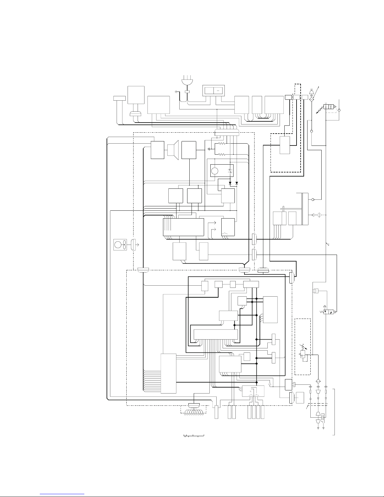
Functional Block Diagram
Functional Block Diagram
Functional Block DiagramFunctional Block Diagram
Functional Block Diagram
Functional Block Diagram
Functional Block DiagramFunctional Block Diagram
EXTERNAL
BATTERY
CONNECTOR
22
INTERNAL
BATTERY
23
BRIDGE
-
+
+
-
RECTIFIER
P2 J2
CORD
GND
LINE
CHASSIS
LP6 Plus, LP10, and LP20 Technical Manual
CONNECTOR
A.C.
P1
20
0
SWITCH
MAIN
CIRCUIT
BREAKER
18
FILTER
RFIIN1
RFIIN2
GND
REAR PANEL
17
RFI
RFIOUT 1
RFIOUT 2
T1
21
SELECTOR
VOLTAGE
SECONDARYA
PRIMARYFUSE
SECONDARYB
XFMR
PRIMARY2B
PRIMARY1B
PRIMARY2A
PRIMARY1A
COMMUNICATIONPORT
REMOTE ALARM
INTERFACE
ALARM
AIR
INLET
J16
MECHANICAL
PRESSURE
RELIEF VALVE
0.3 MICRON
AIR INLET FILTER
1
2
P3
RELAY
A/D
A/DSET
-
CTCWR
DASPEED
+
SELECT
ON/OFF 1
ON/OFF 2
COIL DRIVE
CTCRD
DAMETER
RAM
BATTERY
EEPROM
-
+
CHARGE
CIRCUIT
TRANSISTORS
RO
IO
EPROM1
EPROM2
DRIVE
OSC
CLKWR
+
-
J3
MOTOR
8
+5V
P11
J11
MEMORY COMPONENTS
DAMETER
BRUSHLESS
D.C.
BOARD
CALL
ONLY
CRANK
GEARBOX
9
NURSE
LP20
J10
STROKE
SENSOR
7
END OF
EOT
P10
LOGIC BOARD
XTAL
CLKRD
CTCA
R/W
INT.CUR
EXT.CUR
EXT.VOLT
INT.VOLT
POWER DIODES
RTCLK
CLKWR
CLKRD
MOTOR BOARD
J6
P6
J7
P7
J4 P4
CPU
RESET
Z80A
RD
IO
DATABUS
EPROM1
EPROM2
ADDRESS BUS
EEPROM
RAM
-
1
+
ON
AUDIO
ALARM
AUDIO
CIRCUIT
ALARM
LOW POWER
LEVEL
SHUTDOWN
CONTROL OUT
32
INT.OFF
MODE COM.
CHG. OFF
FAN
35
+12V,GND
J8
J5
P5
110
111
112
EOT
BACKUP SIGNAL
+5 VOLT
REG.
+5V
+12 INPUT
+5
CPU OFF
CPU FORW
CIRCUITRY
BACK UP
ON/OFF
SPEED
VOL
+12V
CONTROL
SPEED
ON/OFF
+12 VOLT
REG.
DRIVE CONTROL
CPU SOL
SOL DRIVER
CONTROL
MOTOR
CTCWR
CTCRD
DRIVER
PRINTSTD
PRINTER
SOLENOID
RESET
CIRCUIT
MOTOUT
MOTRD
BITSOUT
+5V
+12V
CLK
SWITCH1
SWITCH2
SWITCH3
A/DREAD
LED
1MV CHECK VALVE
INLET CHECK VALVE
SEAL RING
PISTON
4
5
11
12
OUTLET CHECK VALVE
VENTILATORMANIFOLD
62 MICRON
GROSS PARTICLEFILTER
PUMP
VENT
14
SOLENOID
VALVE
EXHALATION
LP10 & LP20
ONLY
Page 4-16
Page 4-16
Page 4-16Page 4-16
MODE CCW
KEEP
ALIVE
INT.OFF
CHG. OFF
TONE
AUDIO ON
HOUR METER
CPU FORW
CPU OFF
CPU SOL
H0
H1
H2
EOT SENSOR
MOTRD
MOTOUT
BITSOUT
MOTOR BOARD INTERFACE
LED BOARD
PRESSURE PLATEAUVALVE
VOLTAGE
REF.
DRIVER
REF.
A/DREAD ASSIST
CLKIN
A/DSET
EXT.VOLT
INT.VOLT
EXT.CUR
AMPLIFIED
PRES.
INT.CUR
A/D
PRES.
VOL
DASPEED
PARTICLEFILTER
40 MESH GROSS
13
PRES
FRONT PANEL
XDCR
PATIENTAIR
EXHALATION
51
PRESS/
BATT.
METER
J12
52
FLEXIBLE LINES
PROXIMAL
PRESSURE TUBE
PATIENTMANIFOLD
VALVETUBE
PATIENTCIRCUIT
HOSE
PATIEN T
EXHALATIONVALVE
PATIENTLINE
EXHAUST
SWITCH
INTERFACE
SWITCH3
SWITCH2
ASSIST
SWITCH1
MODE
HIGH PRES.
LOW PRES.
VOL
INSP.TIME
BPM
LED
J9
P9
R
HIGH PRESSURE
LOW POWER
ALARMS
MODE
R
R
LOW PRESSURE APNEA
A
A
G
G
R
R
SETTING ERROR
BREATHINGEFFORT
INTERNAL BATTERY
POWER SWITCH OVER
EXTERNAL BATTERY
A.C. PWR/BATT.CHARGE
POWER MODES
INFORMATIONAL
November 2000
Page 57

5 Maintenance
5 Maintenance
5 Maintenance5 Maintenance
The maintenance section provides the information necessary to maintain the ventilator in optimal operating condition. It outlines those procedures necessary to schedule and perform preventive maintenance
including cleaning and sterilization, troubleshooting, and to make
minor adjustments or repairs that require no special training or instrumentation.
For repair assistance beyond the scope of this manual, contact a Nellcor
Puritan Bennett Customer Service Representative.
Those procedures outlined in this section can be performed
Those procedures outlined in this section can be performed
Warning
Warning
WarningWarning
Maintenance Schedule
Maintenance Schedule
Maintenance Schedule Maintenance Schedule
Those procedures outlined in this section can be performedThose procedures outlined in this section can be performed
by the operator without invalidating the warranty. Nellcor
by the operator without invalidating the warranty. Nellcor
by the operator without invalidating the warranty. Nellcorby the operator without invalidating the warranty. Nellcor
Puritan Bennett, Inc. assumes no responsibility or liability
Puritan Bennett, Inc. assumes no responsibility or liability
Puritan Bennett, Inc. assumes no responsibility or liabilityPuritan Bennett, Inc. assumes no responsibility or liability
for the results of any servicing attempted, beyond that
for the results of any servicing attempted, beyond that
for the results of any servicing attempted, beyond thatfor the results of any servicing attempted, beyond that
listed, by personnel not factory-trained by Nellcor Puritan
listed, by personnel not factory-trained by Nellcor Puritan
listed, by personnel not factory-trained by Nellcor Puritanlisted, by personnel not factory-trained by Nellcor Puritan
Bennett, Inc.
Bennett, Inc.
Bennett, Inc.Bennett, Inc.
Task Frequency
Visual Check As required
Clean Exterior As required
Replace Inlet Filter Weekly; daily if used in transit or outdoors
Replace Bacteria Filter As required
Clean Patient Circuit Daily; minimum three times a week
Clean Exhalation Manifold Assembly Daily; minimum three times a week
Clean Humidifier Twice weekly
Test External and Internal Batteries Monthly
Clean Printer Module As required
November 2000
Page 5-1
Page 5-1
Page 5-1Page 5-1
Page 58

Preventive Maintenance
Preventive Maintenance
Preventive MaintenancePreventive Maintenance
Preventive Maintenance
Preventive Maintenance
Preventive MaintenancePreventive Maintenance
LP6 Plus, LP10, and LP20 Technical Manual
Visual Check
Visual Check
Visual CheckVisual Check
Exterior cleaning
Exterior cleaning
Exterior cleaningExterior cleaning
Frequency
- As required
Procedure (with unit turned off)
PATIENT PRESSURE
Check the
1.
1.
1.1.
division of -10.
Check for cracks on the case or meter face. Check for legible
2.
2.
2.2.
control and indicator identification markings and front panel
Alarm Reference Guide instructions (located on control panel
door).
Check all connections including power,
3.
3.
3.3.
MUNICATIONS PORT
MUNICATIONS PORT
MUNICATIONS PORTMUNICATIONS PORT
printer module, if used.
Frequency -
PAT I E N T PR E S S U RE
PAT I E N T PR E S S U REPATIENT PRESSURE
Examine the cables and connections on the
.
As required
meter. The needle should be within one
EXTERNAL BATTERY
EXTERNAL BATTERY
EXTERNAL BATTERYEXTERNAL BATTERY
and
,
Supplies
❒ liquid detergent
❒ cold disinfectant
❒ cloth
COM-
COM-
COM-COM-
Warning
Warning
WarningWarning
Page 5-2
Page 5-2
Page 5-2Page 5-2
Procedure
Clean the exterior with soap and water or with a bactericidal or
1.
1.
1.1.
germicidal agent.
Clean the display panel with isopropyl alcohol. Do not allow liq-
2.
2.
2.2.
uid cleaning agents to penetrate the inside of the ventilator.
Any liquid leaking into the ventilator or its connections
Any liquid leaking into the ventilator or its connections
Any liquid leaking into the ventilator or its connectionsAny liquid leaking into the ventilator or its connections
may damage the unit or result in an electrical shock haz-
may damage the unit or result in an electrical shock haz-
may damage the unit or result in an electrical shock haz-may damage the unit or result in an electrical shock hazard.
ard.
ard.ard.
November 2000
Page 59

LP6 Plus, LP10, and LP20 Technical Manual
Inlet Filter
Inlet Filter
Inlet FilterInlet Filter
Preventive Maintenance
Preventive Maintenance
Preventive MaintenancePreventive Maintenance
Caution
Caution
CautionCaution
Standard Inlet Filter
Standard Inlet Filter Frequency
Standard Inlet FilterStandard Inlet Filter
Note:
Failure to change the filter may result in serious damage to the
ventilator, and can invalidate the warranty.
Supplies
❒ replacement filter
Procedure
Twist the threaded plastic cap counterclockwise.
1.
1.
1.1.
Remove the screens and the old filter.
2.
2.
2.2.
Wash the screens with soap and water; rinse and dry thoroughly
3.
3.
3.3.
before reinserting.
Check the filter for dust, dirt or discoloration.
4.
4.
4.4.
Filters cannot be cleaned. Replace, if necessary. Any printing on the
replacement filter should face towards the front of the ventilator.
Weekly; daily if used in transit or outdoors
November 2000
Reassemble in reverse order and secure the plastic filter cap.
5.
5.
5.5.
Flatpak Inlet Filter
Flatpak Inlet Filter Frequency
Flatpak Inlet FilterFlatpak Inlet Filter
Supplies
❒ replacement Flatpak filter
Procedure
Twist the retainer ring counterclockwise. See figure on the next
1.
1.
1.1.
page.
Remove and inspect the Flatpak filter for dust, dirt, or discolora-
2.
2.
2.2.
tion. Filters cannot be cleaned. Replace, if necessary.
Reassemble in reverse order, making sure that the retainer ring
3.
3.
3.3.
is tight.
Monthly; weekly if used in transit, outdoors, or dusty
conditions
Page 5-3
Page 5-3
Page 5-3Page 5-3
Page 60
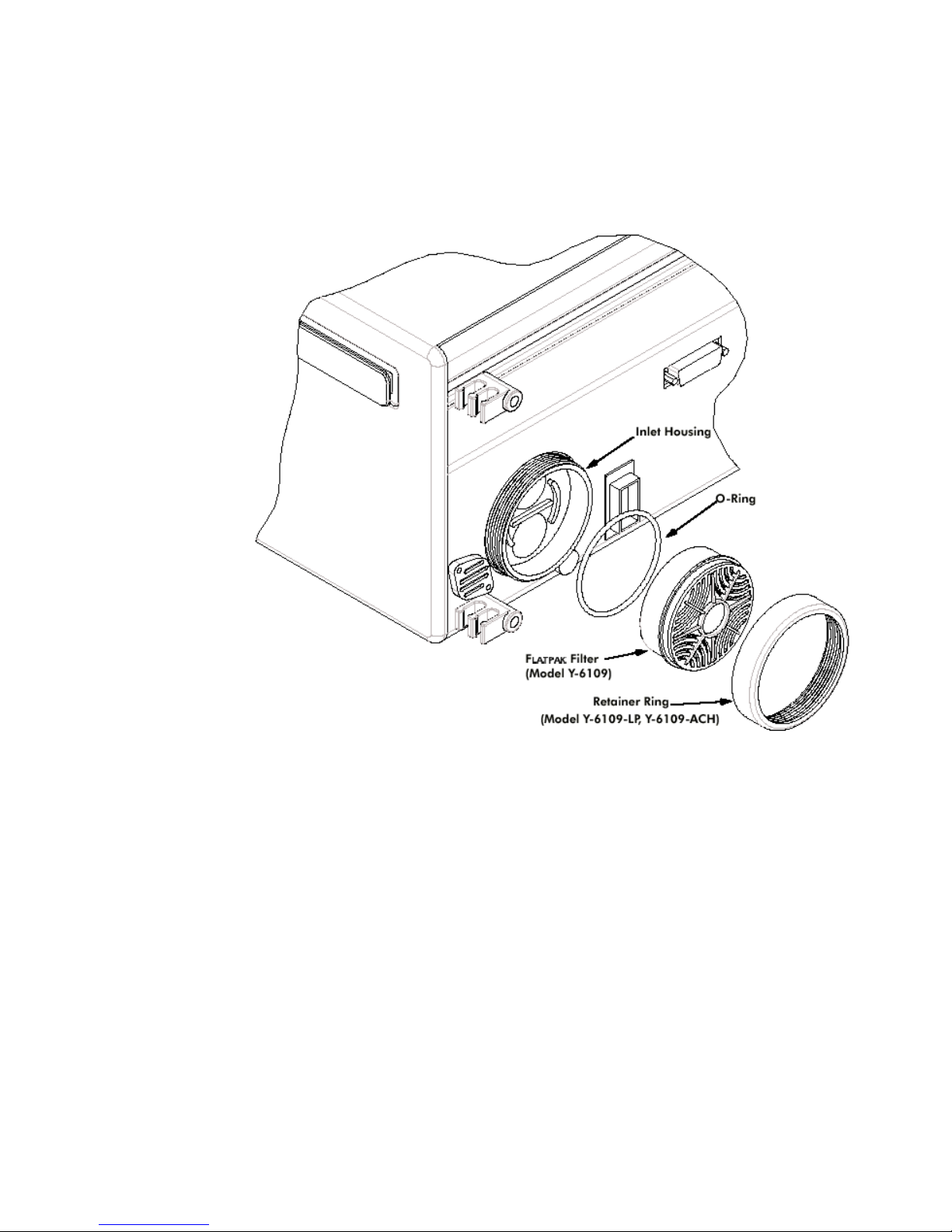
Preventive Maintenance
Preventive Maintenance
Preventive MaintenancePreventive Maintenance
LP6 Plus, LP10, and LP20 Technical Manual
Bacteria Filter
Bacteria Filter
Bacteria FilterBacteria Filter
Page 5-4
Page 5-4
Page 5-4Page 5-4
Flatpak Filter Replacement
Frequency
Supplies
❒ replacement filter
Procedure
Remove the bacteria filter and check for discoloration of the
1.
1.
1.1.
internal filter material.
Replace if needed, or if a new patient is placed on the ventilator,
2.
2.
2.2.
or if four weeks have passed since the last filter change.
As required
November 2000
Page 61

LP6 Plus, LP10, and LP20 Technical Manual
Flextube
Preventive Maintenance
Preventive Maintenance
Preventive MaintenancePreventive Maintenance
Patient Circuit
Exhalation
Manifold
November 2000
Page 5-5
Page 5-5
Page 5-5Page 5-5
Page 62

Preventive Maintenance
Preventive Maintenance
Preventive MaintenancePreventive Maintenance
Patient Circuit
Patient Circuit
Patient CircuitPatient Circuit
Warning
Warning
WarningWarning
LP6 Plus, LP10, and LP20 Technical Manual
Patients requiring ventilation assistance are often highly
Patients requiring ventilation assistance are often highly
Patients requiring ventilation assistance are often highlyPatients requiring ventilation assistance are often highly
susceptible to respiratory infections. Because of dormant
susceptible to respiratory infections. Because of dormant
susceptible to respiratory infections. Because of dormantsusceptible to respiratory infections. Because of dormant
moisture, a patient circuit is an ideal source of infection.
moisture, a patient circuit is an ideal source of infection.
moisture, a patient circuit is an ideal source of infection.moisture, a patient circuit is an ideal source of infection.
Failure to properly clean and disinfect patient circuit com-
Failure to properly clean and disinfect patient circuit com-
Failure to properly clean and disinfect patient circuit com-Failure to properly clean and disinfect patient circuit components may result in added pulmonary complications.
ponents may result in added pulmonary complications.
ponents may result in added pulmonary complications.ponents may result in added pulmonary complications.
Frequency
Daily, minimum three times a week
Supplies
❒ manual resuscitator or backup ventilator
❒ liquid detergent
❒ white vinegar or recommended disinfectants
❒ long bristle and bottle brushes
Procedure
Disassemble as shown on the opposite page.
1.
1.
1.1.
Scrub all parts of the patient circuit using brushes and warm
2.
2.
2.2.
soapy water. Make certain the brush enters each convolution to
remove medication, secretions or other foreign matter.
Rinse all parts under tap water; make certain all residue is
3.
3.
3.3.
removed.
Disinfect the patient circuit using one of the following methods:
4.
4.
4.4.
Page 5-6
Page 5-6
Page 5-6Page 5-6
Soak for 30 minutes in a solution of one part white vinegar to
a.
a.
a.a.
two parts water. Rinse thoroughly.
Soak in an approved chemical disinfectant, following the
b.
b.
b.b.
manufacturer’s instructions.
Shake excess moisture from all parts and place on a clean towel
3.
3.
3.3.
to air dry. Do not wipe or dry with a towel. Do not use a blow
dryer. Tubing must be completely dry before reattaching to the
ventilator.
November 2000
Page 63

LP6 Plus, LP10, and LP20 Technical Manual
Exhalation Manifold Assembly
Exhalation Manifold Assembly
Exhalation Manifold AssemblyExhalation Manifold Assembly
Preventive Maintenance
Preventive Maintenance
Preventive MaintenancePreventive Maintenance
Frequency
Supplies
❒ manual resuscitator or backup ventilator
❒ liquid detergent
❒ white vinegar or recommended disinfectants
❒ long bristle and bottle brushes
Procedure
Unsnap the body and cap.
1.
1.
1.1.
Unscrew the mushroom valve as shown.
2.
2.
2.2.
Clean and disinfect using the procedure given for the patient cir-
3.
3.
3.3.
cuit. Make certain no water or cleaning solution remains in the
mushroom or other valve parts.
When completely dry, screw the mushroom securely into the
4.
4.
4.4.
locking nut and snap the body back into the cap.
Daily, minimum three times a week
Humidifier
Humidifier
HumidifierHumidifier
November 2000
Warning
Warning
WarningWarning
Ensure proper reassembly of the exhalation manifold. Fail-
Ensure proper reassembly of the exhalation manifold. Fail-
Ensure proper reassembly of the exhalation manifold. Fail-Ensure proper reassembly of the exhalation manifold. Failure of the manifold to function as intended could present a
ure of the manifold to function as intended could present a
ure of the manifold to function as intended could present aure of the manifold to function as intended could present a
hazard to the patient.
hazard to the patient.
hazard to the patient.hazard to the patient.
Frequency
Supplies
❒ liquid detergent
❒ scouring powder or steel wool (fine)
❒ autoclave, gas or cold sterilization
Procedure
Twice weekly
Refer to the manufacturer’s manual.
Page 5-7
Page 5-7
Page 5-7Page 5-7
Page 64

Preventive Maintenance
Preventive Maintenance
Preventive MaintenancePreventive Maintenance
LP6 Plus, LP10, and LP20 Technical Manual
External Battery
External Battery
External BatteryExternal Battery
Frequency
Supplies
Monthly
❒ External Battery Charger (optional)
Procedure
With the external battery connected and operating the ventilator,
1.
1.
1.1.
BATTERY TEST
press the
BATTERY CONDITION
BATTERY CONDITION
BATTERY CONDITIONBATTERY CONDITION
the
Check the external battery hookup. Make certain the cable con-
2.
2.
2.2.
BATTERY TEST
BATTERY TESTBATTERY TEST
NORMAL
to
nections are correct and the terminals are not corroded.
The external battery will be charged by the ventilator in any
MODE
MODE
position. The ventilator will fully charge a 12 V deep cycle
MODEMODE
battery, in good condition, in approximately three hours of
charge time for each hour of use.
For faster charging time, disconnect the battery from the ventilator and attach it to an appropriate external charging device.
button on the front panel and observe the
indicator on the meter. The needle should be in
range.
HIGH
Internal Battery
Internal Battery
Internal BatteryInternal Battery
Frequency
Supplies
Monthly
None required
Procedure
With the internal battery operating, disconnect AC power and
1.
1.
1.1.
the external battery from the ventilator.
BATTERY TEST
Press the
2.
2.
2.2.
BATTERY CONDITION
BATTERY CONDITION
BATTERY CONDITIONBATTERY CONDITION
NORMAL
NORMAL
the
NORMALNORMAL
BATTERY TEST
BATTERY TESTBATTERY TEST
indicator on the meter. The needle should be in
HIGH
HIGH
to
HIGHHIGH
range.
button on the front panel and observe the
Page 5-8
Page 5-8
Page 5-8Page 5-8
November 2000
Page 65

LP6 Plus, LP10, and LP20 Technical Manual
Preventive Maintenance
Preventive Maintenance
Preventive MaintenancePreventive Maintenance
Printer Module
Printer Module
Printer ModulePrinter Module
Caution
Caution
CautionCaution
The following routine procedure is listed here for your convenience.
For more detailed instructions, refer to the instructions which
accompanied the unit.
Do not operate the Printer Module without paper. This can
cause permanent damage to the unit.
Procedure
Disconnect AC power.
1.
1.
1.1.
Clean the Printer Module using a damp sponge and a mild
2.
2.
2.2.
household detergent. Keep liquid from entering the unit.
Check the power and ribbon cables for physical damage.
3.
3.
3.3.
BATTERY
Connect to an operating ventilator. Press the ventilator’s
4.
4.
4.4.
switch three times within two seconds; verify that a printout
TEST
TEST
TESTTEST
is produced.
BATTERY
BATTERYBATTERY
November 2000
Page 5-9
Page 5-9
Page 5-9Page 5-9
Page 66

Preventive Maintenance
Preventive Maintenance
Preventive MaintenancePreventive Maintenance
LP6 Plus, LP10, and LP20 Technical Manual
Page 5-10
Page 5-10
Page 5-10Page 5-10
November 2000
Page 67

6 Troubleshooting
6 Troubleshooting
6 Troubleshooting6 Troubleshooting
This table provides procedures for identifying and correcting operator
problems. This list includes only those problems correctable without
special equipment. Refer problems beyond the scope of this section to
an authorized Nellcor Puritan Bennett Service Representative.
Troubleshooting Chart
Troubleshooting Chart
Troubleshooting ChartTroubleshooting Chart
Symptom
Symptom Cause
SymptomSymptom
Cause Solution
CauseCause
Solution
SolutionSolution
Green AC power light is out with
unit connected to AC power
Power light ON, but ventilator
fails to cycle
Alarms activate when unit is
turned on
Low Pressure alarm sounds frequently
AC Power Switch Move switch to ON
No AC power at outlet Check for 110 VAC at outlet
Open Circuit Breaker Reset by moving AC switch to ON
Defective cord or connector Check cord and connector for possi-
ble loose connections.
Defective LED Contact Nellcor Puritan Bennett
Mode switch in Standby position
Normal test of audible and
visual indicators
Incorrect alarm settings Check alarm control setting
Improper patient connections Check patient connection (trach)
Leaks in components or connections
Water in small tubing Remove water
No patient circuit is connected to unit; no pressure is
registered
Pressure Limit control is overtightened (LP10, LP20)
Move MODE switch to an active
position
Not applicable; Alarms automatically reset
for a secure, leakproof fit
Check all connections, especially
the humidifier and exhalation valve
Connect circuit with test lung to
achieve proper pressure according
to alarm set point
Do not overtighten the Pressure Limit
control
November 2000
Page 6-1
Page 6-1
Page 6-1Page 6-1
Page 68

Troubleshooting Chart
Troubleshooting Chart
Troubleshooting ChartTroubleshooting Chart
Symptom
Symptom Cause
SymptomSymptom
Cause Solution
CauseCause
LP6 Plus, LP10, and LP20 Technical Manual
Solution
SolutionSolution
Low pressure alarm sounds, is
reset, but alarm light remains on
and alarm triggers again in
approximately one minute
High Pressure alarm sounds frequently
Patient unable to receive
assisted breath
Unit cycles continually in 1:1 I/E
ratio in Assist/Control mode
Patient seems inadequately
ventilated; no alarms sound
The initial cause of the alarm
has not been corrected
Incorrect alarm setting Check alarm control setting
Moisture in large tubing Drain tubing
Crimped tubing Make certain tubing is unbent and
Trach or airway restriction Check trach; suction patient
Exhalation Manifold occluded Ensure manifold operates properly
Incorrect Pressure Limit Setting
(LP10 and LP20)
BREATHING EFFORT set to negative
Moisture in small tubing Drain tubing
Improper BREATHING EFFORT
control setting
Incorrect VOLUME setting Check VOLUME control setting
Low ventilator output Check exhaled volume
Leaks, not sufficient to trip
LOW PRESSURE alarm
High Pressure Limit set too low
in Pressure Cycle mode
Incorrect Pressure Limit Setting
(LP10 and LP20)
Check for leaks
Check for proper control setting
Check Volume setting
Possible change in patient compliance
open
Check Pressure Limit control
Check setting
Check BRATHING EFFORT control setting
Check potential leak locations
Contact health care provider for
prescription change
Check Pressure Limit Control
Page 6-2
Page 6-2
Page 6-2Page 6-2
November 2000
Page 69

LP6 Plus, LP10, and LP20 Technical Manual
Symptom
Symptom Cause
SymptomSymptom
Cause Solution
CauseCause
Solution
SolutionSolution
Troubleshooting Chart
Troubleshooting Chart
Troubleshooting ChartTroubleshooting Chart
Ventilator connected to external battery but INTERNAL BATTERY power light flashing
Audible alarm sounds, LOW
POWER light illuminates, AC
power off
All alarm lights on steady; continuous alarm
Unit not switching to external
battery
Low charge on external battery
Loose or broken connections Check all connectors for broken or
Internal battery low Change to adequate external bat-
Unit has detected a microprocessor error
Internal battery depleted Charge Internal battery
Check DC power cord; check for
blown fuse in DC power circuit;
check DC circuit breaker
Connect to AC power; recharge
external battery
missing pins, or loose connections.
tery or to AC power; Recharge internal battery by connecting to AC
power
Turn unit OFF; wait 10 seconds, then
turn the unit back ON. If the alarm
situation still exists, do not use the
ventilator. Turn it OFF and contact
your Service Representative
November 2000
Page 6-3
Page 6-3
Page 6-3Page 6-3
Page 70

Alarm Condition Chart
Alarm Condition Chart
Alarm Condition ChartAlarm Condition Chart
Alarm Condition Chart
Alarm Condition Chart
Alarm Condition ChartAlarm Condition Chart
Audio
Audio
Alarm
Alarm LED
AlarmAlarm
LED
LEDLED
Audio Audio
Alarm
Alarm
AlarmAlarm
Alarm
Alarm
Alarm Alarm
Silence
Silence
SilenceSilence
Reset
Reset/
ResetReset
Switch
Switch
SwitchSwitch
/
/ /
LP6 Plus, LP10, and LP20 Technical Manual
Self
Self
Self Self
Cancel
Cancel
Cancel Cancel
Visual/
Visual/
Visual/ Visual/
Audible
Audible
AudibleAudible
Resulting
Resulting
Resulting Resulting
calibrator
calibrator
calibrator calibrator
& printer
& printer
& printer & printer
test
test
testtest
Resulting
Resulting
Resulting Resulting
effect on
effect on
effect on effect on
machine
machine
machine machine
operation
operation
operationoperation
Alarm Test All LEDs Alarm for 1
second
Start-up All LEDs Alarm for 2
seconds
Microprocessor Error
High Pressure High Pressure Pulsing alarm 60 second
Excess Pressure
Low Power L ow Power Puls ing alar m 60 second
Charger
Fault
Low Pressure Low Pres-
All LEDs Continuous
alarm
High Pressure Pulsing alarm 60 second
Low Power Pulsing alarm 60 second
Pulsing alarm 60 second
sure/apnea
n/a both none none
n/a both n/a n/a
n/a n/a n/a No
silence
silence
silence
silence
silence
ventilation
audible HIGH PRESS Piston
retracts and
mushroom
deflates
audible EXCESS
PRESS
none LOW POWER none
none CHARGER
FAU LT
none
(audible on
LP20)
LOW PRESS none
Piston
retracts and
mushroom
deflates
none
Valley Pressure
Exhale Failure
Page 6-4
Page 6-4
Page 6-4Page 6-4
Low Pressure/Apnea
Low Pressure/Apnea
Pulsing alarm 60 second
Pulsing alarm 60 second
silence
silence
none
(audible on
LP20)
none
(audible on
LP20)
VA LL E Y
ALARM
EXHALE FAIL No delivery
none
until
pressure
decreases
November 2000
Page 71

LP6 Plus, LP10, and LP20 Technical Manual
Audio
Audio
Alarm
Alarm LED
AlarmAlarm
LED
LEDLED
Audio Audio
Alarm
Alarm
AlarmAlarm
Alarm
Alarm
Alarm Alarm
Silence
Silence
SilenceSilence
Reset
Reset/
ResetReset
Switch
Switch
SwitchSwitch
/
/ /
Self
Self
Self Self
Cancel
Cancel
Cancel Cancel
Visual/
Visual/
Visual/ Visual/
Audible
Audible
AudibleAudible
Alarm Condition Chart
Alarm Condition Chart
Alarm Condition ChartAlarm Condition Chart
Resulting
Resulting
Resulting Resulting
calibrator
calibrator
calibrator calibrator
& printer
& printer
& printer & printer
test
test
testtest
Resulting
Resulting
Resulting Resulting
effect on
effect on
effect on effect on
machine
machine
machine machine
operation
operation
operationoperation
Stall Low Pres-
sure/Apnea
Apnea Low Pres-
sure/Apnea
Power
Switchover
Inverse I/E
setting
BPM Error Setting Error Pulsing alarm 60 second
Vo lu m e
Error
Inspiratory
Effort
Mode Switch Setting Error Pulsing alarm 60 second
Power
Switchover
Setting Error Pulsing alarm Test both INVERSE I:E Delivers at
Setting Error Pulsing alarm 60 second
Setting Error Pulsing alarm 60 second
Pulsing alarm 60 second
silence
Pulsing alarm Reset none APNEA Apnea
Pulsing alarm Reset none POWER
silence
silence
silence
silence
none STALL No delivery
mode of
ventilation
none
SWITCHOVER
set inspiratory at 1:1 I:E
audible RATE ERROR none
audible VOL ERROR none
audible INS ERROR none,
except to
maintain
max I:E of 1:1
audible MODE
SWITCH
ERROR
may default
to
ventilating
mode
Self test Over
Pressure
Va l ve Fa il
Selftest Leak
Test Fail
November 2000
High Pressure Pulsing alarm 60 second
Low Pressure Pulsing alarm 60 second
silence
silence
both OVP VALVE
FAILU RE
both LEAK TEST
FAILU RE
Perform self
test then
function as in
standby
mode
Perform self
test then
function as in
standby
mode
Page 6-5
Page 6-5
Page 6-5Page 6-5
Page 72

Alarm Condition Chart
Alarm Condition Chart
Alarm Condition ChartAlarm Condition Chart
Alarm
Alarm LED
AlarmAlarm
LED
LEDLED
Audio
Audio
Audio Audio
Alarm
Alarm
AlarmAlarm
Alarm
Alarm
Alarm Alarm
Silence
Silence
SilenceSilence
Reset
Reset/
ResetReset
Switch
Switch
SwitchSwitch
/
/ /
LP6 Plus, LP10, and LP20 Technical Manual
Self
Self
Self Self
Cancel
Cancel
Cancel Cancel
Visual/
Visual/
Visual/ Visual/
Audible
Audible
AudibleAudible
Resulting
Resulting
Resulting Resulting
calibrator
calibrator
calibrator calibrator
& printer
& printer
& printer & printer
test
test
testtest
Resulting
Resulting
Resulting Resulting
effect on
effect on
effect on effect on
machine
machine
machine machine
operation
operation
operationoperation
No EOT Sensor
Wrong EOT
sensor
Hall Code
Error
CTC Error Setting Error Pulsing alarm Reset n/a TIMER ERROR none
EEPROM Error Setting Error Pulsing alarm 60 second
Pressure Setting Error
Dynamic
RAM Test
Error
Setting Error Pulsing alarm 60 second
silence
Setting error Pulsing alarm 60 second
silence
Setting Error Pulsing alarm 60 second
silence
silence
Setting Error Pulsing alarm Test both PRESURE SET-
All LEDs Continuous
alarm
n/a n/a n/a No ventila-
audible EOT SENSOR
FAILU RE
audible EOT/HALL
ERROR
audible HALL ERROR none
audible EEPROM
WRONG
TINGS
Ve nt i la t or
resynchronizes with a
seek cycle
Ve nt i la t or
resynchronizes with a
seek cycle
Machine
runs on calibration constants
System uses
and displays
set limits
tion
Dynamic
ROM Test
Error
10 Hz Task
Ending
Page 6-6
Page 6-6
Page 6-6Page 6-6
All LEDs Continuous
alarm
All LEDs Continuous
alarm
n/a n/a n/a No ventila-
tion
n/a n/a n/a No ventila-
tion.
November 2000
Page 73

7 Schematics
7 Schematics
7 Schematics7 Schematics
This chapter contains the schematics and mechanical drawings for Nellcor
Puritan Bennett’s LP6 Plus, LP10, and LP20 Volume Ventilators. This chapter
contains proprietary information. It is intended for use only by qualified individuals in the installation and maintenance of the ventilator. Receipt, purchase, or possession of this document in no way confers or transfers any
other rights for the use of this information. Disclosure or reproduction of the
enclosed, without the written permission of Nellcor Puritan Bennett, Inc., is
prohibited.
November 2000
Page 7-1
Page 7-1
Page 7-1Page 7-1
Page 74
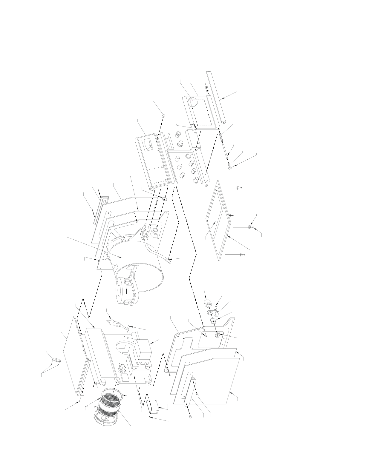
Final Assembly
/
Final Assembly
Final AssemblyFinal Assembly
Final Assembly
Final Assembly
Final AssemblyFinal Assembly
SIDERAIL
FHCS (2)
10-32 X 3/4
RIGHT COVER
LP6 Plus, LP10, and LP20 Technical Manual
OVERLAY
DOOR
DOOR
PLUG
METER ADJUSTMENT
FRONT PANEL
ASSY.
RIGHT SOUND FOAM
O-RING
STRIP
MAGNET
SPRING
DOOR
ROD (2)
HANDLE
WASHER (2)
TEFLON
SPRING (2)
CRESCENT
BOTTOM
FEET (4)
PISTON, AND MOTOR/GEARBOX)
RIGHT END ASSY. (MANIFOLD,
BOTTOM
NYLON
CABLE TIE
FHCS (6)
10-32 X 1/2
BACK PANEL ASSY.
TOP COVER
HIGH PRESSURE RELIEF
VALVE COVER
AC POWER
CORD
LEFT END PLATE
10-32 X 1/2
WARNING LABEL
BATTERY
INTERNAL
SOUND FOAM
ALARM
6-32 X 1/4
BHCS (2)
ALARM
BRACKET
NUT
FHCS (6)
ALARM
ALARM
GASKET
SHCS (4)
6-32 X 3/8
BOTTOM COVER
16
FHCS (2)
6-32 X 5
Page 7-2
Page 7-2
Page 7-2Page 7-2
BHCS (2)
6-32 X 1/4
SCREEN (2)
FILTER SUPPORT
O-RING
INTAKE
NAME TAG
FILTER
BHCS (4)
TRANSFO RMER
6-32 X 1/4
FHCS (2)
SIDERAIL
10-32 X 3/4
LEFT SOUND FOAM
LEFT COVER
November 2000
Page 75
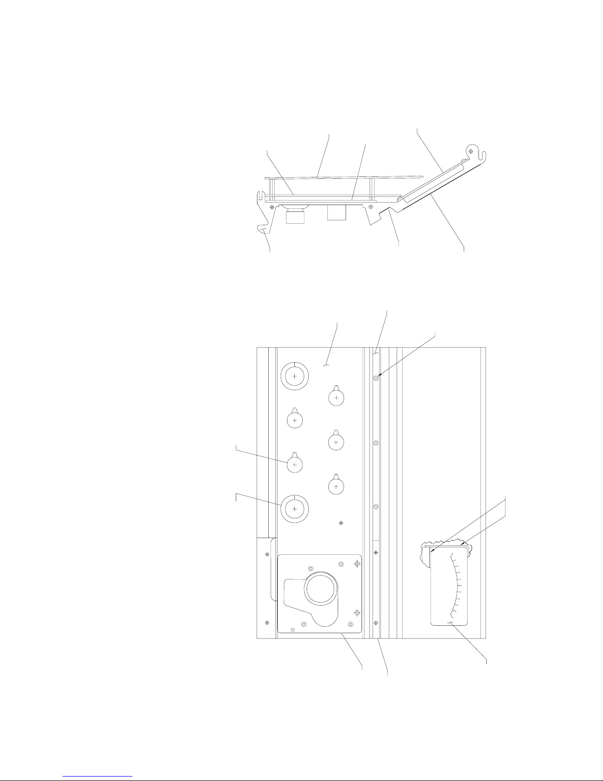
LP6 Plus, LP10, and LP20 Technical Manual
Front Panel (LP6 Plus, LP10)
Front Panel (LP6 Plus, LP10)
Front Panel (LP6 Plus, LP10)Front Panel (LP6 Plus, LP10)
BOARD
LOGIC
FRONT PANEL
POWER/MOTOR
BOARD
OVERLAY
BOTTOM
GASKET
PAN EL
Front Panel (LP6 Plus, LP10)
Front Panel (LP6 Plus, LP10)
Front Panel (LP6 Plus, LP10)Front Panel (LP6 Plus, LP10)
DISPLAY
BOARD
FRONT
STRIP
STRIKER
PLATE
DECORATIVE
BLUE LOCTITE 242 (3)
TOP OVERLAY
4-40 X 3/8 FHMS,
KNOB (5)
FOAM TAPE
PUSHTOTURNKNOB,
O-RING, NYLON WASHER (2)
FRONT PANEL
GASKET
BEZEL
GASKET
METER
November 2000
Page 7-3
Page 7-3
Page 7-3Page 7-3
Page 76
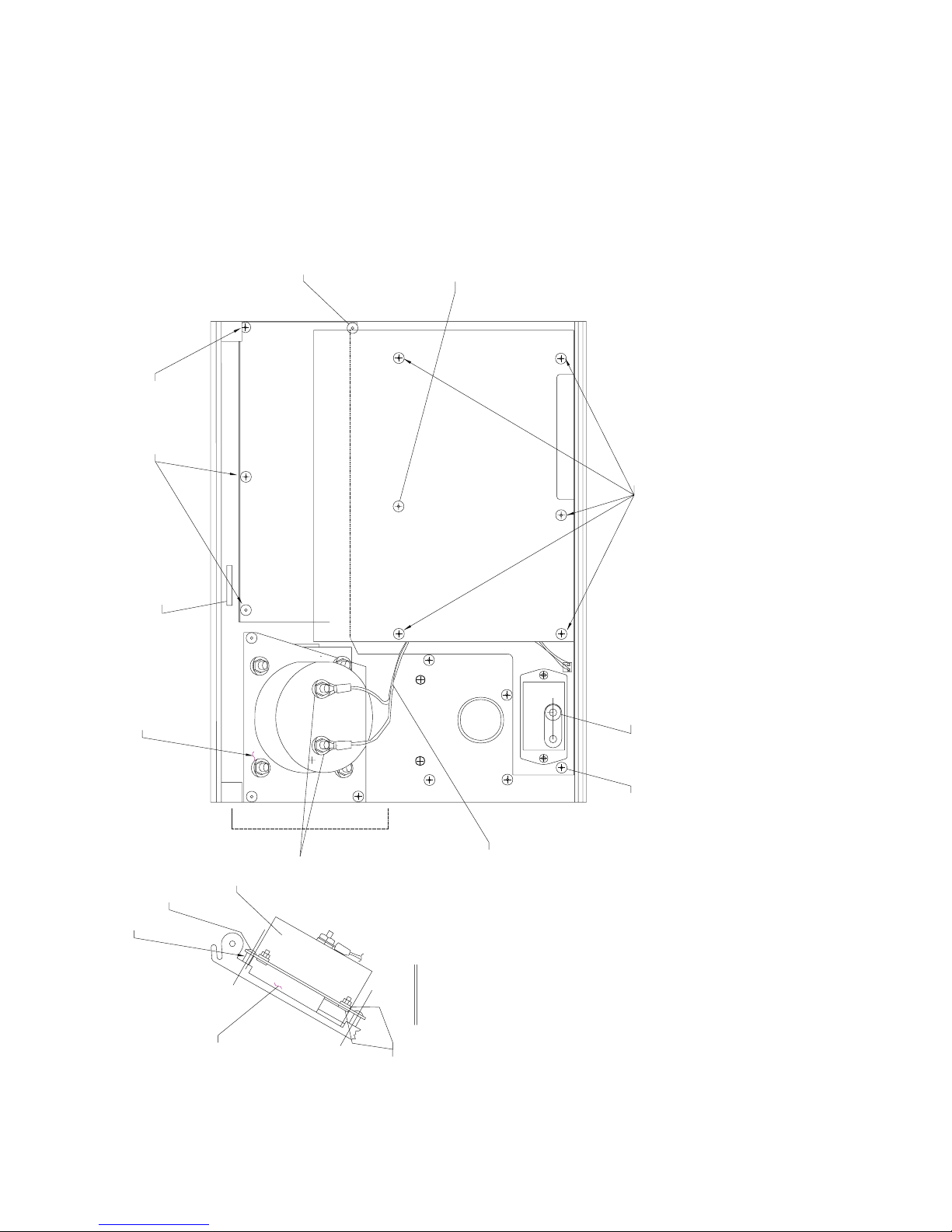
Front Panel (LP6 Plus/LP10)
Front Panel (LP6 Plus/LP10)
Front Panel (LP6 Plus/LP10)Front Panel (LP6 Plus/LP10)
Front Panel (LP6 Plus/LP10)
Front Panel (LP6 Plus/LP10)
Front Panel (LP6 Plus/LP10)Front Panel (LP6 Plus/LP10)
6-32 X 3/16 SLOTTED FLAT
COUNTERSUNK SCREW (3),
BLUE LOCTITE 242
BHCS
6-32 X 3/16
4-40 X 3/16 BHCS,
4-40 X 11/16 STANDOFF,
4-40 X 1/4 STANDOFF
LP6 Plus, LP10, and LP20 Technical Manual
6-32 X 3/16 BHCS,
6-32 X 11/16 STANDOFF,
6-32 X 1/4 STANDOFF
METER
STANDOFF (3)
6-32 X 1/4
LABEL
SERIAL #
BRACKET
6-32 X 3/16
J1
BLK
TRANSDUCER SLEEVE,
RED
A
METER
BHCS (3)
10-32
KEPS NUT
A
METER WIRING
P2P1
ASSY.
PRISM 410 LOCTITE
6-32 X 3/16 BHCS,
6-32 X 1/4 STANDOFF
VIEW A-A
FOAM TAPE
Page 7-4
Page 7-4
Page 7-4Page 7-4
#4 WASHER (8)
November 2000
Page 77
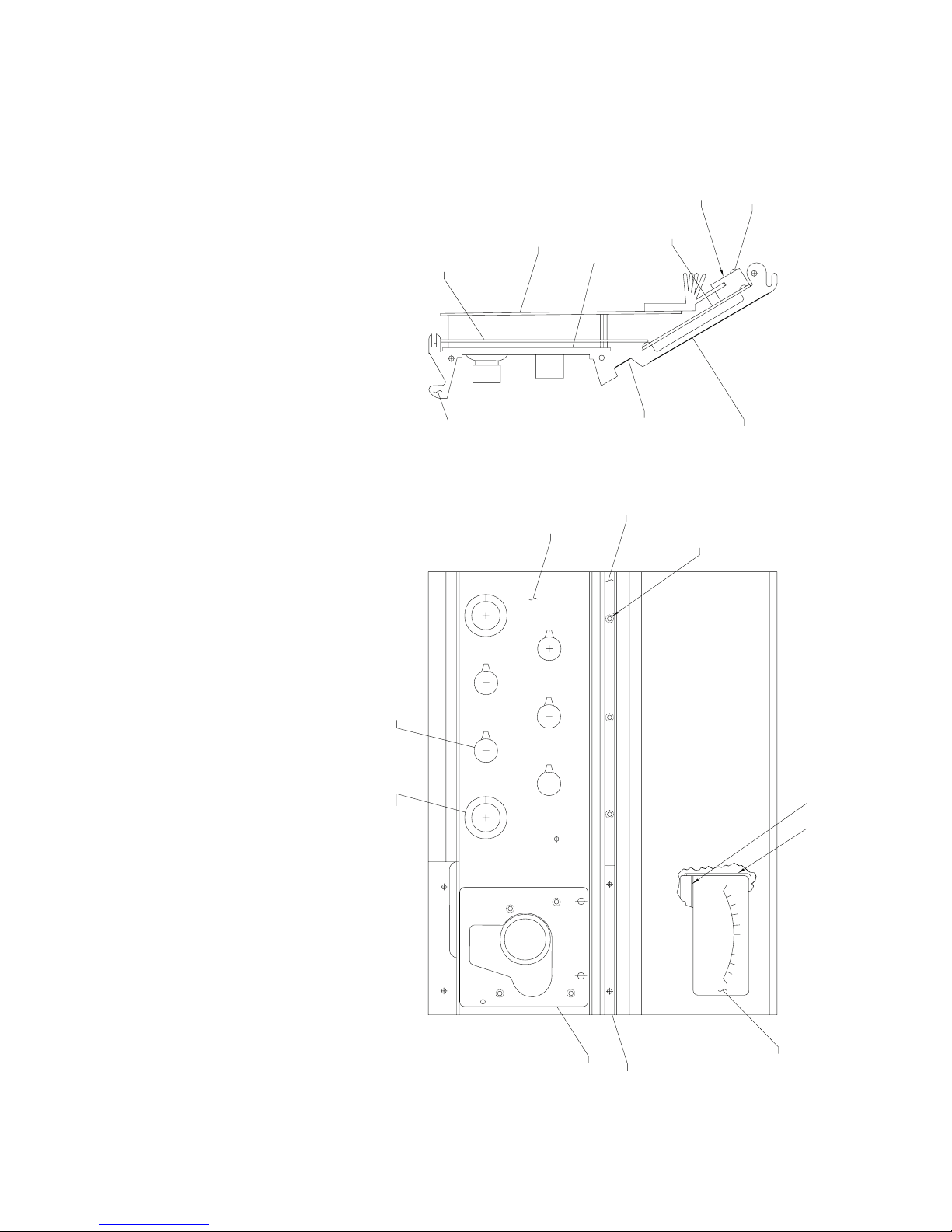
LP6 Plus, LP10, and LP20 Technical Manual
Front Panel (LP20)
Front Panel (LP20)
Front Panel (LP20)Front Panel (LP20)
BOARD
LOGIC
FRONT PANEL
POWER/MOTOR
BOARD
OVERLAY
BOTTOM
GASKET
PANEL
FRONT
STRIKER
PLATE
STRIP
DECORATIVE
Front Panel (LP20)
Front Panel (LP20)
Front Panel (LP20)Front Panel (LP20)
HEAT SINK
DISPLAY
BOARD
DAMPENER
BLUE LOCTITE 242 (3)
4-40 X 3/8 FHMS,
6-32 x 3/4
BHCS
TOP OVERLAY
O-RING, NYLON WASHER (2)
KNOB (5)
PUSH TO TURN KNOB,
FRONT PANEL
GASKET
BEZEL
GASKET
FOAM TAPE
METER
November 2000
Page 7-5
Page 7-5
Page 7-5Page 7-5
Page 78
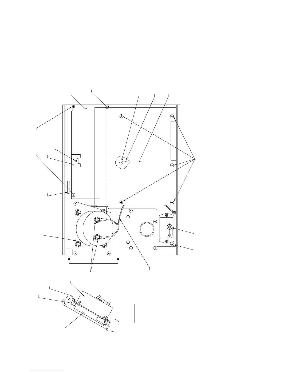
Front Panel (LP20)
Front Panel (LP20)
Front Panel (LP20)Front Panel (LP20)
Front Panel (LP20)
Front Panel (LP20)
Front Panel (LP20)Front Panel (LP20)
6-32 X 3/16 SLOTTED FLAT
COUNTERSUNK SCREW (3),
DISPLAY BOARD
BLUE LOCTITE 242
4-40 X 3/16 BHCS,
4-40 X 1/4 STANDOFF
LOGIC BOARD (BELOW)
LP6 Plus, LP10, and LP20 Technical Manual
POWER/MOTOR BOARD (ABOVE)
BHCS
6-32 X 3/16
METER
HEAT SINK
DAMPENER
LABEL
SERIAL #
BRACKET
6-32 X 3/4
BHCS
6-32 X 3/16 BHCS,
6-32 X 11/16 STANDOFF,
6-32 X 1/4 STANDOFF
J1
BLK
TRANSDUCER SLEEVE,
RED
A
A
P2P1
PRISM 410 LOCTITE
6-32 X 1/4
STANDOFF (3)
Page 7-6
Page 7-6
Page 7-6Page 7-6
6-32 X 3/16
METER
BHCS (3)
FOAM TAPE
10-32
KEPS NUT
#4 WASHER (8)
VIEW A-A
ASSY.
METER WIRING
6-32 X 3/16 BHCS,
6-32 X 1/4 STANDOFF
November 2000
Page 79
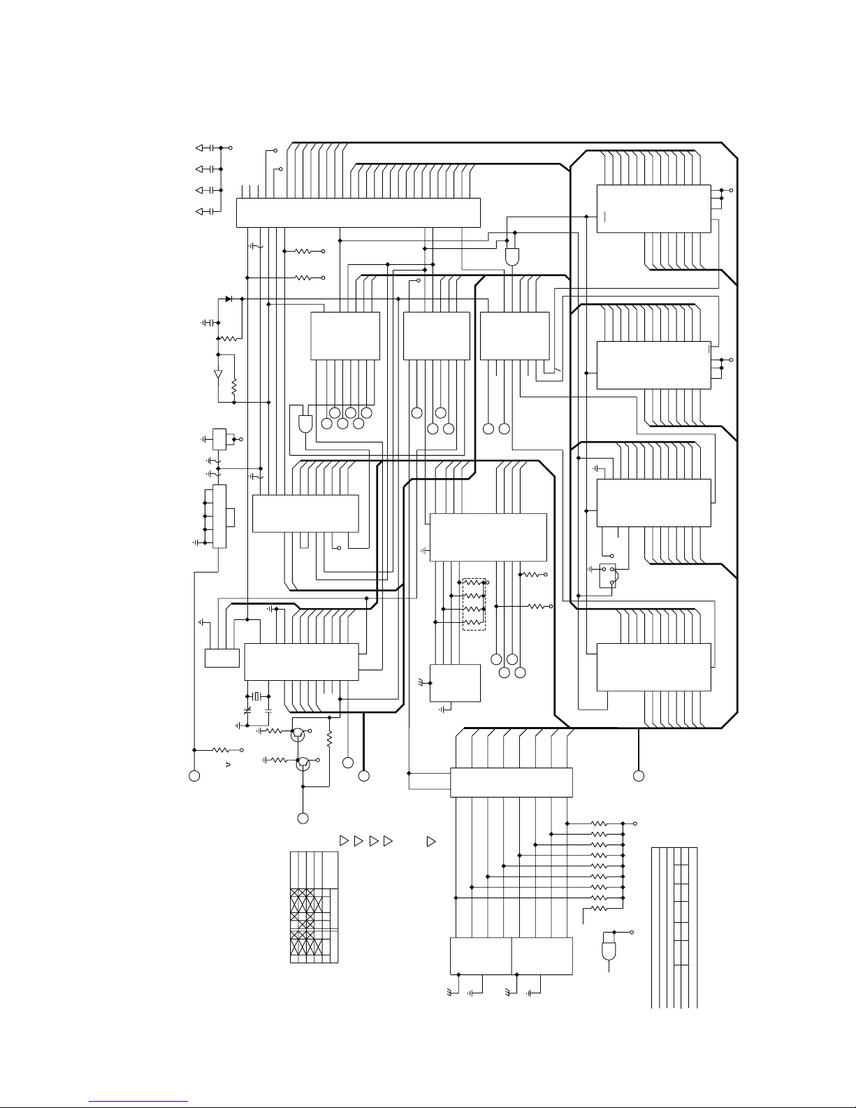
LP6 Plus, LP10, and LP20 Technical Manual
Through-Hole Logic Board
Through-Hole Logic Board
Through-Hole Logic BoardThrough-Hole Logic Board
Through-Hole Logic Board
Through-Hole Logic Board
Through-Hole Logic BoardThrough-Hole Logic Board
+12V
.01
C18
C19
.01
C20
.01
C21
.01
CR5
1N4148
C3
.1
1M
R7
9
1/4 W,5%
U8D
4050
10
4 MHz
U27
1
7
0
14
8
10
1
2
9
3
11
12
74LS293
13
U11
4
D0
CLKRD
4
1
3
2
TP1
4M, 1MOL
TOD
CALIBRATE
CLOCK
3-32
C1
pf
R36
1K
1%
1/2 W
500 KHz
SH
S
3
+5V
D5
D3
D1
D4
D2
D6
D7
+5V
NC
NC
NC
23
CLK<
6
15
MHz
CLK
4
RDY
XTAL 1
ALL DIODES
ARE
1N4148.
25
17
RES
26
17
RES
X2
11
C2, 22
pf
R35
1K
4.75K
VALUES
CAPACITOR
ARE
IN
V
OHMS, 1/8W
ALUES
ARE IN
, 1%; ALL
MICROF
ARADS;
M1
27
14
M1
12
GND
R34
1. UNLESS OTHERW
ISE SPECIFIED, ALL RESIST
OR
INT
INT
A1
CE
A4
13
16
12
19
A1
1
9
10
10K
10K
74LSO8
5
CTCRD
D7
4
TR3
A0
18
A0
D7
22
56187
8
A3
SH
R
2
3
4
U7B
D6
3
20
D6
21
7
A2
28
18
W
T
24
R6, 10M
+5V
X1
10
32 KHz
+5V
9
7
R1
R5
4
6
D5
2
Z02
9
D5
20
U10
6
A1
+5V
2N2907
Q6
2N2907
DISABLE
CLOCK
2
D4
I0
D4
1
W
RITE
7
CLKW
R
1
10
IO*
19
5
A0
Q5
12
8
+5V
+5V
6
EN
74LS138
6
9
7
ADSEL
L
SH
3
D3
28
RD
6
RD*
D3
18
STBY
INT OUT
INT
14
N.C.
+5V
POSITION
3
COM
4
2
1
COM
14
15
W
R
22
W
R*
W
R*
5
EN
U22
5
4
10
11
MOTOUT
PRINTSTB
K
J
SH
SH
2
2
D1
D2
27
26
Z80 CTC
IEI
13
+5V
D1
D2
16
17
PWDN
13
23
N.C.
100K
R33
2. MODE SW
ITCH
TRUTH
SECTION
T
ABLE (REF)
1
SECTION
3
D0
A15
5
IO*
3
4
C
EN
3
12
BITSOUT
I
H
SH
2
D0
25
U9
CE
16
D0
15
RD
W
R
+
24
Q
SH
2
3. TWO
TO
CHASSIS
P
ADS
FOR
GND
ST
(REF) PLUS EXTRA
ANDOFF BOTH
SIDES
W
IRE P
OF J10
AD.
A13
A14
4
3
(SOCKET)
A7
A6
2
B
2
1
13
14
DAMETER
DASPEED
G
SH
3
SH
3
CLKRD
2
3
AX
5. FORM
SHOWN
LEADS
.
ON
SW1, SW2, SW3 AND
SW4 AS
A12
2
A5
1
A
0
15
CTCWR
28 PIN
P
ATTERN
AND
INST
ALL JP1 AS SHOWN.
Z80A
A10
A11
40
1
U28
CLKWR
6. INSTALL U1 PIN
OF A COMPONENT.
1IN
PIN
3 LOCA
TION
OF
A8
A7
A9
39
38
37
6
EN
READ
7
7
SWRD3
F
SH
3
7. SQUARE
CATES PIN
FASTENING.
P
ADS ON
1, (+) POLARITY
PC
BOARD, ITEM
,OR
CA
THODE
1, INDI-
A5
A6
35
36
RD
21
RD*
RD*
+5V
5
EN
EN
74LS138
U21
6
5
9
10
ADREAD
SWRD2
E
SH
2
SWRD2
1
19
8. ENSURE INSULATOR
SWITCH
SHOULDER
AND
IS NOT PINCHED
P
.C.B. BEFORE
BETWEEN
A4
34
IO
20
IO*
A7
IO*
3
4
C
4
3
12
11
DISSTB
SW
RD1
D
SH
2
D7
17
OE
OE
18
8
SWRD3
19
HIGH
PRESS
33
C
SH
2
D6
15
16
4
1
A2
A3
32
A6
1
2
A
B
2
1
13
14
CLKRD
MOTRD
D5
13
14
2
C
D7
17
OE
OE
18
8
A5
12
1
A1
31
MEM
19
MEM*
0
15
CTCRD
D4
11
5
4
2
3
SW
3
4
A6
D6
18
D6
4
A6
D6
18
D6
4
A6
D6
18
D6
2
A6
D6
16
D6
A6
A6
A6
A6
J1 THRU
J8
A5
D5
A5
D5
A5
D5
A5
D5
A5
5
17
D5
A5
5
17
D5
A5
5
17
D5
A5
3
15
D5
P1 THRU
P3
A4
6
A4
D4
16
D4
A4
6
A4
D4
16
D4
A4
6
A4
D4
16
D4
A4
4
A4
D4
14
D4
REF DESIGNATION
NOT USED
A3
7
A3
D3
15
D3
A3
7
A3
D3
15
D3
A3
7
A3
D3
15
D3
A3
5
A3
2816
D3
13
D3
R36
C74
Q6
CR8
JP1
P5
TP2
RP7
U28
SW5 XDCR1
J12
XT
AL1
A1
A2
A0
10
9
8
A1
A2
A0
1
+5V
26
27
CE
20
D1
D2
D0
ROM0
11
12
13
/
D1
D2
D0
A1
A2
A0
ROM2
10
9
8
A1
A0
A2
CE
20
11
+5V
26
D2
D1
D0
27
11
12
13
D1
D2
D0
A1
A2
A0
10
9
8
RAM
A1
A2
A0
CE
20
D1
D2
D0
11
12
13
D1
D2
D0
A1
A2
A0
8
7
6
EEPROM
A1
A2
A0
U24
CE
18
D1
D2
D0
11
10
9
D1
D2
D0
HIGHEST REF DESIGNATION
USED
A12
A11
A10
A8
A7
A9
A0
30
RD*
2
1
74LS08
U7A
3
MEM*
A15
A13
A14
3
4
5
EN
74LS138
U23
6
5
9
10
LEDOUT
A
SH
2
D2
D3
3
5
2
4
O
SH2
D4
11
12
1
SW1
EN
4
11
EEPROM
D1
7
74LS795
6
N
M
SH2
SH2
C
3
12
RAM
D0
9
U4
8
2
3
D3
3
2
8
2
B
2
13
NC
10K
10K
74LS795
U6
1
A
0
1
15
14
1
+5V
RP6
1
RP6
D2
5
4
4
C
6
EN
MEM
7
7
NC
PRINTOUT
B
SH
2
1
+5V
10K
RP2
P
INS TIME
SH2
D6
D5
15
13
16
14
2
4
C
22
WR*
RD*
ROM0
ROM2
22
WR*
22
2
+5V
RD*
20
W
R*
D1
D0
9
7
6
8
5
6
10
3
8
7
4
9
2
NC
2
1
SPARE
LOW
SW2
PRESS
25
21
23
24
3
2
A12
A11
A7
A10
A8
A9
(SOCKET)
2764-0
U25
OE
OE
OE
CE
OE
D7
19
D7
A12
A11
A10
A8
A7
A9
25
21
23
24
3
2
A12
A7
A10
A11
A8
A9
(SOCKET)
2764-2
U26
D7
19
D7
A8
A10
A7
A9
27
25
21
24
3
2
WR
A7
A10
A8
A9
6264
U1
D7
26
1
23
19
NC
D7
+5V
1
JP1
3
A8
A7
A10
A9
23
22
19
1
A7
A10
A8
A9
(SOCKET)
WR
D7
17
21
D7
DX
Reference only
Reference only
Reference onlyReference only
+5V
1
1
1
RP1
10K
1
1
1
1
1
1
+5V
13
12
11
U7D
74LS08
November 2000
Page 7-7
Page 7-7
Page 7-7Page 7-7
Page 80
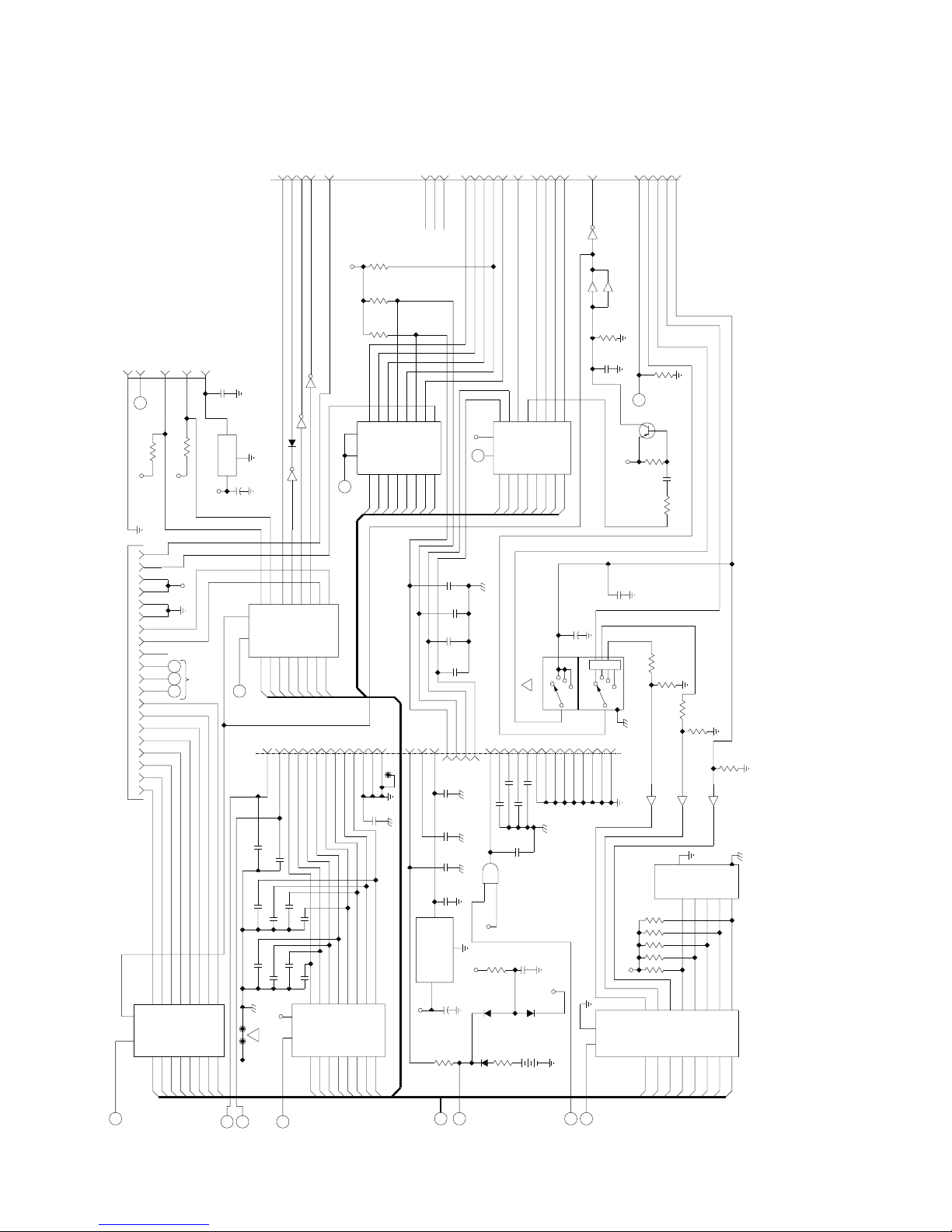
Through-Hole Logic Board
Through-Hole Logic Board
Through-Hole Logic BoardThrough-Hole Logic Board
Through-Hole Logic Board
Through-Hole Logic Board
Through-Hole Logic BoardThrough-Hole Logic Board
LP6 Plus, LP10, and LP20 Technical Manual
Reference only
Reference only
Reference onlyReference only
REMOTE
ALARM
TO
3
1
M
SH 1
RES
LD
2
ONE
CONT
2-T
REM
REM
1K
R9
1K
+5V
+5V
NC
P
O
N
9
6
16
15
12
U2
74LS273
14
7
13
8
17
D4
D3
D2
D1
D0
J11
Y BOARD
J9
DISPLA
TO
BACKUP*
LEDOUT
A
4
R8
+5V
6
8
20
19
18
17
7
9
5
10
11
12
13
14
1
2
3
4
16
15
1
11
SH 1
4050
U8F
SH 1
.1
RP2
14
22V BUS
CLOCK DISABLE
R
10K
RP7
4050
U8A
1
1
1
10K
1
1
8
9
D0
2
2
1
3
2
BUS
ALARM
Q3
R10
C4
.01
R12
5
BPM
6
7
D1
13
15
MODE
POWER
ALARM
RUNNING
R31
47.5K
2N2907
100K
1K
RP7
10K
10K
RP7
4050
U8B
C
SW4
10
6
9
7
8
4
5
D2
17
6
4
3
5
4
1
2
U3
3
D3
RP7
9
4050
2
12
74LS795
11
D4
U8C
4
10K
10
RP7
10K
7
8
7
6
8
16
16
18
14
13
15
17
D5
D6
D7
4
16
16
U13
15
D4
GND)
NOT USED
(ANALOG
4
18
74LS795
5
17
D6
D5
30
33
Q2
+12V
1
NC
2
3
D7
34
3
OUT
78L05
IN
18
NC
C58
C57
680
C56
C55
BUSY
SPARE
21
C61
680
C60
680
680
C59
.1
C49
GND
C48
47
+
R2
100K
DX
10
5
1312
P5
ON
ONE
OFF*
T
SENSE
AUDIO
AUDIO
INT BATT OFF*
CHARGE
AC POWER
7406
9
15
8
14
D2
D1
32
1
DISSTB
PRINTSTB
pf
680
C64
pf
pf
680
680
C70
pf
pf
680
680
C66
+5V
PRINTOUT
7
D3
C71
C67
B
1N4002
CR1
6
5
U14C 7406
6
17
D4
3
1
11
U14A
2
7406
1
U14B
4
3
5
2
16
19
U12
74LS273
4
3
18
D6
D5
D7
9
7
5
pf
680
C72
pf
680
C68
6
9
RES
LD
7
8
4
D2
D1
D0
1
SH
5
.1
+8 REG
C74
3
OUT
78L08
2
GND
IN
Q1
1
+
47
C73
63V
+12V
12
1
RES
11
LD
BACKUP*
13
BITSOUT
SH 1
5
19
4
18
D6
D5
D0
I
SH 1
J10
pf
680
C63
pf
680
C69
pf
680
C65
2
3
3
D7
E
K
SH 1
SH 1
11
5
U5
MOTRD
13
2
12
74LS273
3
13
D3
D4
RP6
10K
4
1
+5V
RP6
10K
6
RP6
10K
5
8
6
12
14
19
OE
1
OE
7
9
11
13
C
D3
D0
D2
D1
SH 1
6
4
15
17
2
TP2
pf
C62
680
16
15
19
18
17
14
D7
D6
D5
21
20
23
19
24
22
HALL 2
HALL 1
HALL 0
+5V
J
SH1
pf
680
pf
680
pf
pf
680
SER OUT
CAL ERROR LED
27
26
23
pf
pf
pf
9
+5V
2
+12V
63V
CR3
CR2
Q
SH 1
SPARE (INPUT)
1
11
MOTOUT
D0
29
8
10
R3
CRANK SENSOR*
9
12
RES
LD
13
8
D1
19
25
pf
pf
680
C51 680
C52
U7C
1K
1K
R4
(HOUR METER) NOT USED
6
15
14
D3
D2
28
pf
680
C53
C50
680
74LS08
C24
BAT1
+
CPU FWD
WATCHDOG
16
U15
74LS273
7
17
D4
2
(MODE SW)
SW5
31
8
pf
680
C54
pf
.01
CR4
BH1
3V
CPU OFF*
5
4
D5
BAT HLD
8
6
BACKUP
CPU SOL*
8
SOLENOID #2
2
19
18
3
D6
D7
+
1
SECTION 3
COM
12
14
10
+5V
AO
SH 1
4050
U8E
C23
AX
47
16
9
12
11
63V
3
SECTION 1
18
20
19
1
SWRD1
D
U14D
15
14
1M
R11
C5
WATCHDOG
2
4
COM
22
OE
OE
1
SH
7406
.1
+5V
C22
24
+5V
7
11
9
Page 7-8
Page 7-8
Page 7-8Page 7-8
November 2000
Page 81
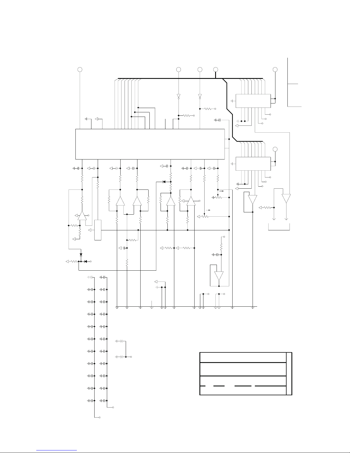
LP6 Plus, LP10, and LP20 Technical Manual
Through-Hole Logic Board
Through-Hole Logic Board
Through-Hole Logic BoardThrough-Hole Logic Board
Through-Hole Logic Board
Through-Hole Logic Board
Through-Hole Logic BoardThrough-Hole Logic Board
332K
SH
S
1
500 KHz
13
10
GND
CLK
IN1
IN0
26
C12
.1
C11
.1
7
100K
RP4
8
100K
26.7K
R25
U18A
LM324
1
11
+12V
4
-
+
OUT
3
2
R26
100K
R27
-
2
CR6
CR7
+5V
.01
C46
C26
.01
.01
C27
.01
C28
10K
R32
D7
D6
D5
D4
D3
D2
D1
D0
N.C.
25
16
REF-
27
5
RP4
6
100K
3
+
1
120 cm
XDCR1
.01
C47
.01
C36
.01
C37
C38
.01
18
19
21
20
IN4
2
.1
C13
7
100K
RP3
8
U20D
LM324
14
7
RP5
-
+
8
13
12
R24
10K
.1
C10
2.21K
EXTERNAL CURRENT
CURRENT GND
10
11
23
14
24
17
15
8
SEL C
IN5
3
C14
.1
5
100K
RP3
6
U20C
LM324
8
+
9
10
R21
10K
R23
100K
R22
INTERNAL CURRENT
12
EOC
SEL A
SEL B
.1
1N4148
CR8
RP5
5
R20
150K
100K
6
100K
100K
NC
4313
9
SH
L
1
ADSEL
13
U14F
7406
12
1K
6
22
7
ST
ALE
ADC0809
IN6
4
C15
3
.1
C9
100K
RP3
4
26.7K
R30
U20B
R17
150K
LM324
7
11
-
+
5
6
3
100K
RP5
4
R19
100K
EXTERNAL VOLTS
SH
DX
F
1
ADREAD
11
7406
U14E
10
+5V
R15
1K
+5V
R16
C25
.01
9
OE
U19
IN2
IN7
5
.1
C8
1
RP3
100K
2
U20A
LM324
1
+12V
4
-
+
2
3
1
1
RP5
LN1
LK NUT
2
R18
INTERNAL VOLTS
6145
+
+REF
IN3
28
1
C7
.1
1
3
100K
RP4
100K
RP4
2
4
CW
2
1
3
R29
10K
LN2
LK NUT
CW
2
3
(EFFORT)
10K
R28
100K
C6
.1
5
6
-
+
LM324
7
+5V
+12V
+5V
7
8
11
12
(VOLUME)
+5V
R14
U18B
+12V
2
-
10
-
10
VOLUME
WR2
WR2
D7
D6
D5
D4
D3
D2
D1
13
14
15
16
5
4
6
AGND
XFER
ILE
I01
I02
VR
18
D7
13
XFER
18
19
17
12
11
3
8
D3
D5
D2
D4
D1
D6
15
16
14
4
5
6
AGND
ILE
I02
I01
VR
8
12
17
11
3
19
10
9
+
U18C
LM324
8
SPEED
P4
1
SH
H
1
DAMETER
D0
7
CS
WR1
+
20
+5V
+5V
D0
7
CS
WR1
+
20
+5V
+5V
4.75K
R13
1
2
+12V
1
2
+12V
J12-2
DAC0832
SH
1
G
DASPEED
DAC0832
U16
U17
-
TO
METER
13
J12-1
LP20
LP6+/10
MODEL
12
+
U18D
LM324
14
.01
.01
C39
C29
.01
.01
C40
C30
.01
C31
.01
C32
.01
C33
.01
C34
.01
C35
63V
.01
C41
63V
.01
C42
.01
C43
.01
C44
.01
C45
+5V
+5V
November 2000
Reference only
Reference only
Reference onlyReference only
Reference only
Reference only
Reference onlyReference only
+
47
C17
+5V
+
47
C16
U14
7406
14
7
U8
4050
1
8
U19
0809
SEE
DWG
U20
LM324
SEE DW
G
U5
LS273
20
10
U3
LS795
20
10
U4
LS795
20
10
U6
LS795
20
10
U16
0832
SEE
DW
G
U17
0832
SEE
DWG
U18
LM324
SEE DW
G
U15
LS273
20
10
U12
LS273
20
10
U22
U13
LS138
LS795
16
20
10
8
U21
LS138
16
8
U2
LS273
20
10
U10
58167
SEE DW
G
U9
CTC
24
5
U24
2816
24
12
U1
6164
28
14
U26
2764
28
14
U25
2764
28
14
U28
Z80A
11
29
U23
LS138
16
8
U7
LSO8
14
7
U27
OSC
14
7
U11
IC
LS293
TYPE
PWR/GND
BUS
+5V
14
GND
7
Page 7-9
Page 7-9
Page 7-9Page 7-9
Page 82
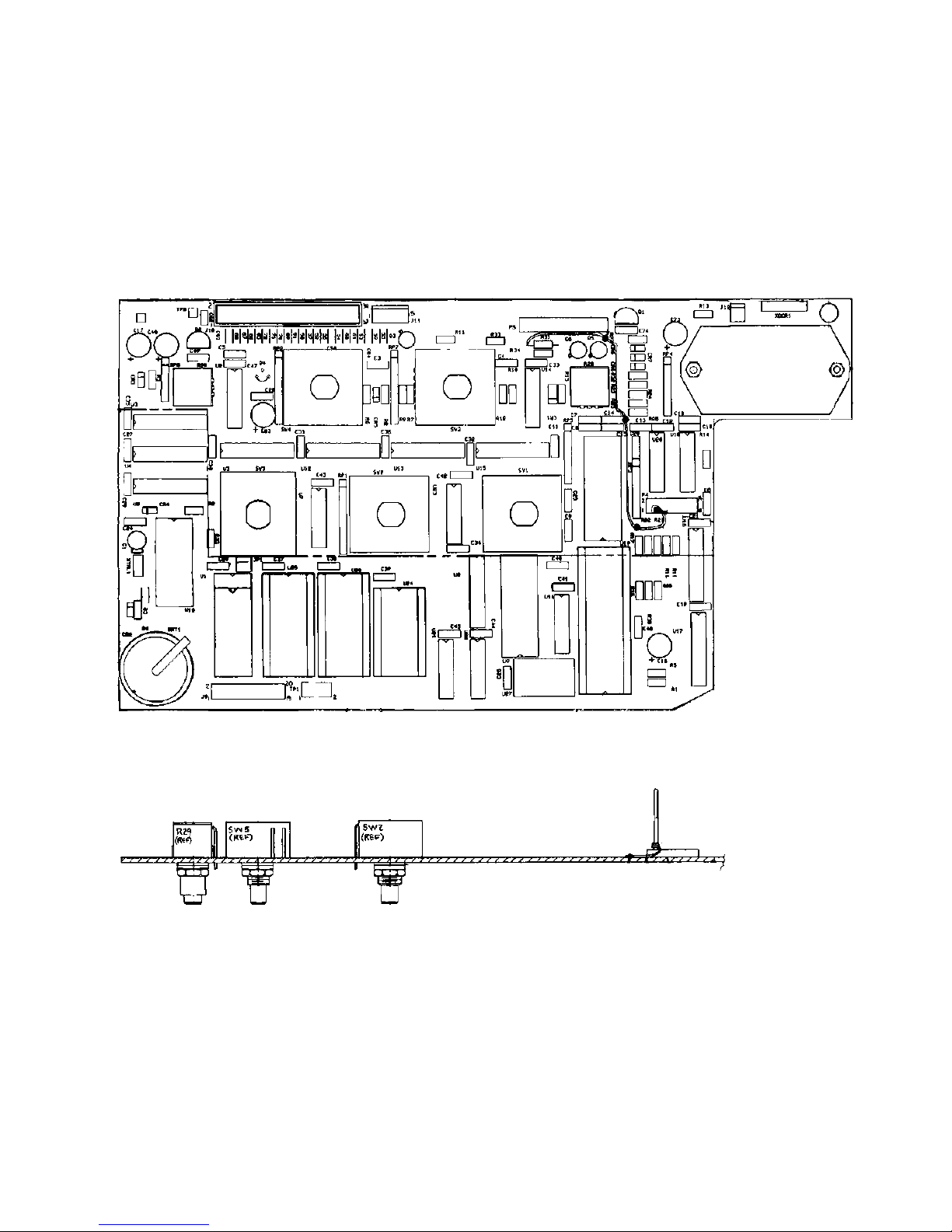
Through-Hole Logic Board
Through-Hole Logic Board
Through-Hole Logic BoardThrough-Hole Logic Board
Through-Hole Logic Board
Through-Hole Logic Board
Through-Hole Logic BoardThrough-Hole Logic Board
Reference only
Reference only
Reference onlyReference only
LP6 Plus, LP10, and LP20 Technical Manual
Page 7-10
Page 7-10
Page 7-10Page 7-10
November 2000
Page 83
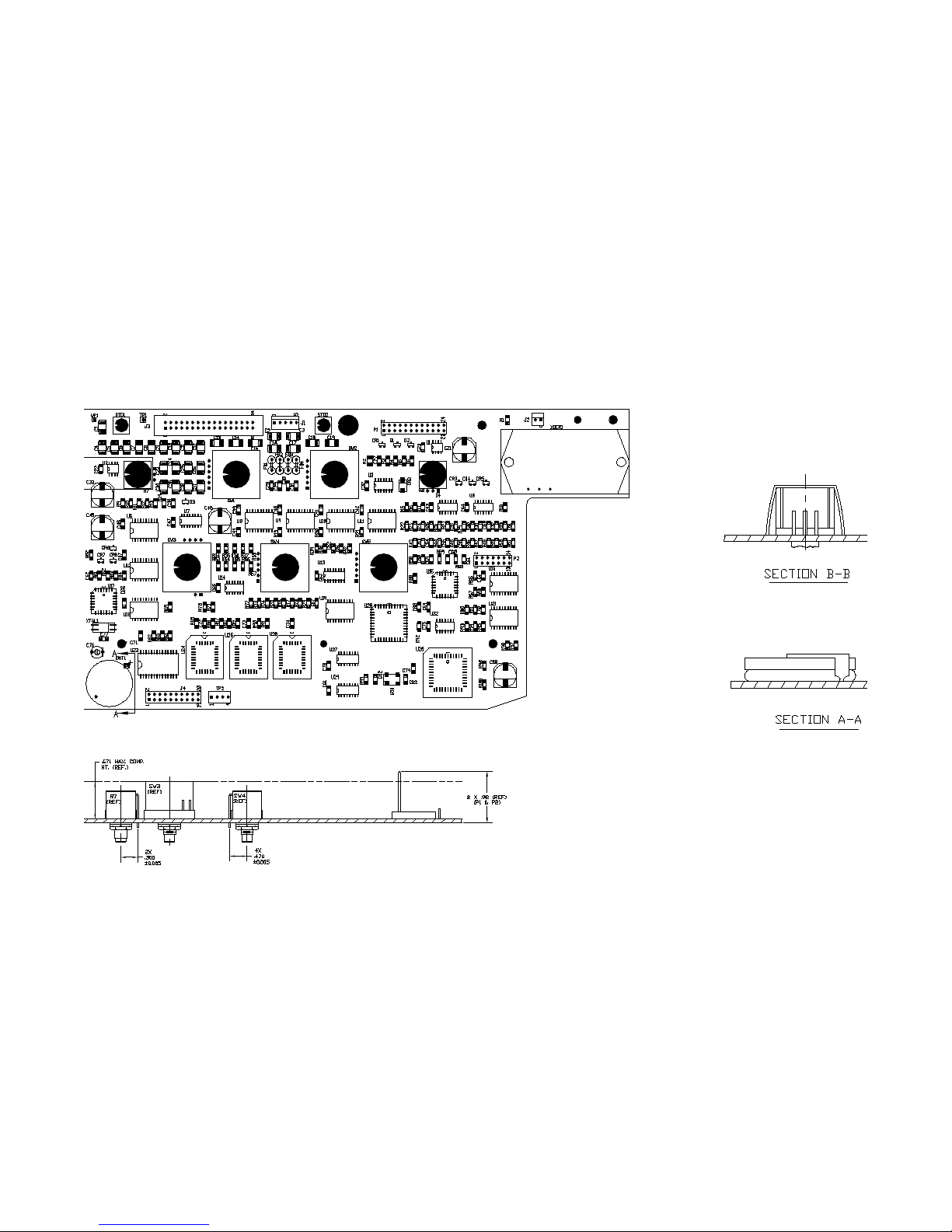
LP6 Plus, LP10, and LP20 Technical Manual
Surface-Mount Logic Board
Surface-Mount Logic Board
Surface-Mount Logic BoardSurface-Mount Logic Board
Surface-Mount Logic Board
Surface-Mount Logic Board
Surface-Mount Logic BoardSurface-Mount Logic Board
Reference only
Reference only
Reference onlyReference only
November 2000
Page 7-11
Page 7-11
Page 7-11Page 7-11
Page 84
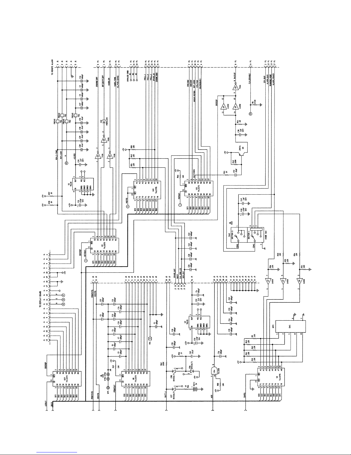
Surface-Mount Logic Board
Surface-Mount Logic Board
Surface-Mount Logic BoardSurface-Mount Logic Board
Surface-Mount Logic Board
Surface-Mount Logic Board
Surface-Mount Logic BoardSurface-Mount Logic Board
LP6 Plus, LP10, and LP20 Technical Manual
Reference only
Reference only
Reference onlyReference only
Page 7-12
Page 7-12
Page 7-12Page 7-12
November 2000
Page 85
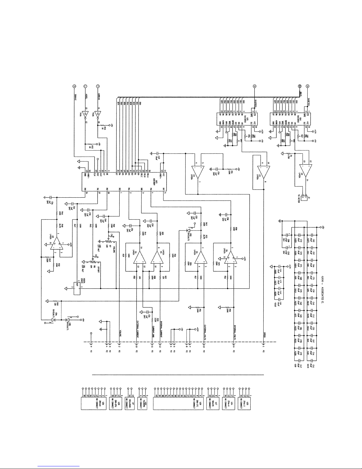
LP6 Plus, LP10, and LP20 Technical Manual
Surface-Mount Logic Board
Surface-Mount Logic Board
Surface-Mount Logic BoardSurface-Mount Logic Board
Reference only
Reference only
Reference onlyReference only
Surface-Mount Logic Board
Surface-Mount Logic Board
Surface-Mount Logic BoardSurface-Mount Logic Board
November 2000
Page 7-13
Page 7-13
Page 7-13Page 7-13
Page 86

Surface-Mount Logic Board
Surface-Mount Logic Board
Surface-Mount Logic BoardSurface-Mount Logic Board
Surface-Mount Logic Board
Surface-Mount Logic Board
Surface-Mount Logic BoardSurface-Mount Logic Board
LP6 Plus, LP10, and LP20 Technical Manual
Reference only
Reference only
Reference onlyReference only
Page 7-14
Page 7-14
Page 7-14Page 7-14
November 2000
Page 87
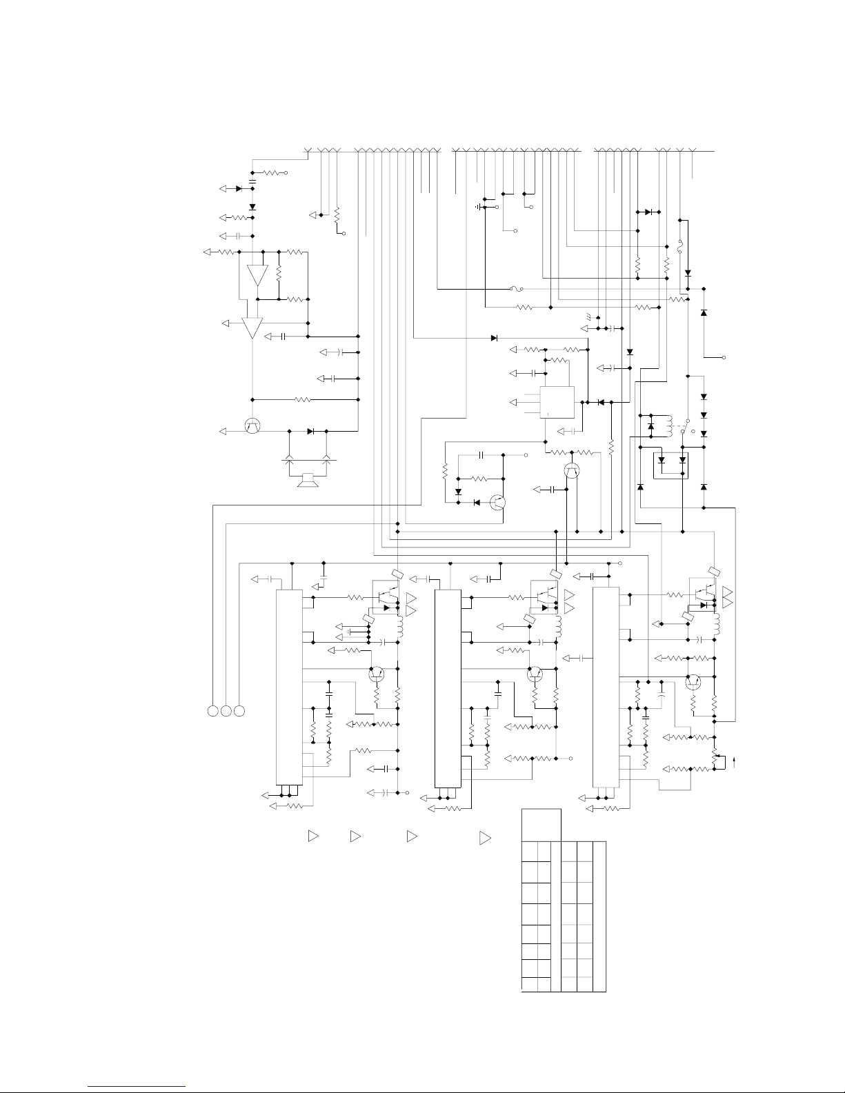
LP6 Plus, LP10, and LP20 Technical Manual
Through-Hole Power-Motor Board
Through-Hole Power-Motor Board
Through-Hole Power-Motor BoardThrough-Hole Power-Motor Board
20
19
GND
(ANALOG)
63V
+
4
GND
(HOUR
(ANALOG)
METER)
C27
47
C40
.01
J1
NOT USED
4.75K
17
10
5
NOT USED
CHARGER
ALARM
POW
OFF
(AUDIO
ER
*
T
R47
ONE)
+5V
NC
+
18
16
14
15
13
3
2
1
22V
CLOCK DISABLE
INT BAT
AC
POWER
BUS
OFF
SENSE
*
RUNNING
MODE
NC
NC
ALARM
BUS
221K
J5
1N4148
9
NC
R71
Reference only
Reference only
Reference onlyReference only
10K
1N4148
CR15
100K
.01
R64
LM393
12
AUDIO
+5V
ON
10K
R66
.1
C34
1N4148
CR14
R63
C33
82.5K
6
-
LM393
2
-
+
4
U11
1
PN2222
R62
5
+
U11
100K
R65
7
22.1K
R69
3
8
.01
C39
10K
R5
1N4002
Q23
CR10
J2
-
Through-Hole Power-Motor Board
Through-Hole Power-Motor Board
Through-Hole Power-Motor BoardThrough-Hole Power-Motor Board
14
13
12
10
+12V
2N2907
1.0A
+12V
Q22
+12V
F2
274K
NC
NC
+5V
26.7K
.1
11
EXTERNAL VOLTS
CURRENT GND
INTERNAL VOLTS
+5V
+5V
R74
R4
332K
R3
C1
3
TH
8212
6
U4
G
5
O
7
4
+5V
R1
10K
C26
1
50V
J4
INTERNAL CURRENT
EXTERNAL CURRENT
221K
R2
2
HY
+
8
C41
.01
10K
2N2907
2
5
3
487
6
1
REM
CHASSIS GND
GND
16 VAC
60 Hz
OVED
-FW
RECT
NC
2
+
12000
C2
1N4002
2
+
47
C25
63V
1N4002
CR5
R11
1.5K
R70
Q3
EXTERNAL BAT-
162K
MR751
CR6
.05, 3W
R55
R10
CR9
1N4002
1N5401
CR4
CR8
FUSED
INTERNAL BAT
EXTERNAL BA
-
T+
R56,
.05, 3W
221K
9
R9
RLY 1
1
1
SPEED
CR20
1N4148
2
.47
100K
NC
CR21
4
GND
1N4002
C46
R73
GND
(DIGIT
AL)
38765
GND
(DIGIT
AL)
TP1
CR19
10
J3
INTERNAL BAT+
NC
F1
6.3A
1N4002
CR17
1N4002
CR18
+12V
CR1
1N5401
COM
1N5401
CR2
1N5401
CR3
2
CR13
1605CT
1N5401
HS2
CR7
S. LIGHT4G. MERTZ
C
SPEED
D. REBISKIE
.01
C38
12
5
C32
.01
VCC
CT
C1
8
C2
11
E1
9
E2
10
2+
OC
1%; ALL CAPACITOR
MICROFARADS
V
ALUES
ARE
IN
TL494
13
U3
GND
DT
7
2.21K
1. UNLESS
RESISTOR
OTHER
V
ALUES
W
ISE
ARE IN
SPECIFIED, ALL
OHMS, 1/8W
,
2-
COMP
1-
RT
REF
1+
R16
16
15
3
2
6
14
1
22V
+ REG
BUSS
A
B
L. LANGE
2
``HSI'' HEATSINK FOR
9PIC
'S.
R15,
1M
2W
2
4.7K
2
C5,
.1
C6
.1
47.5K
R14
9
RP2
4.7K
10
(MUST ACCEPT #6 SCREW
S-REF).
R12
330
RP2
1
2N2907
6
4.7K
RP2
7
4.7K
4. HOLES
(3) NOT T
O
FILL W
ITH
SOLDER
Q4
5
RP2
CATHODE OF A COMPONENT.
3
2
+
1400
C9
4.75K
R18
4
4.7K
RP2
8
.01
C8
10
C7
5. SQUARE
INDICATES PIN
P
ADS ON
1, (+) POLARITY
PC
BOARD, ITEM
,OR
1
4
Q2
PIC625
2
6
1
100UH
.5, 3W
3
+
6
INST
AROUND
& FIT IN
ALL FERRITE BEADS, ITEM
CLEARANCE
PINS2&4OFQ1,Q2,&Q6,
BORES OF HS1,ITEM
15 REF
,
6.
R17
+5V
12
.01
VCC
U1
DT
7
2.21K
C1
C2
E1
E2
2+
2-
COMP
1-
RT
REF
1+
4
R67
C36
8
11
9
10
16
15
3
R19,
1M
2
6
14
1
RLY1.
7
8
9. FORM
LEADS OF
CR6 T
O
CLEAR
CR4 AND
.1
47.5K
4.7K
R24
330
2W
2
4.7K
1
RP3
2
2N2907
C11,
.1
C10
6
R20
RP3
4.7K
RP3
4.75K
R59
5
.01
C30
CT
L3
TL494
GND
OC
13
5
Q5
C45,
Q21
C3
C4
U5
CR16
U8
U6
CR12
Q6
.01
4
PIC625
3
2
6
2
1
100UH
L2
+
C12
1400
.01
C31
.5, 3W
4.75K
R22
R23
4
3
RP3
4.7K
+12V
6.81K
R21
C29,
C42
RLY1
R74
R6
RP8
R7
F2
REF DESIGNATION
C46
TP1
R61
CR21
Q23
R8
J8
L3
NOT
R13
U1
USED
1
R39
R44
R46
C35
5
VCC
CT
TL494
U2
GND
OC
DT
13
7
2.21K
HIGHEST REF
DESIGNA
TION
USED
12
C1
C2
E1
E2
2+
2-
COM
P
1-
RT
REF
1+
R68
+REG
Q1
4
PIC625
3
8
11
9
10
16
15
3
1M
2
6
14
1
4
330
2W
R37
2
1400
4.75K
R36
2N2907
C14,
+
R27
1M
1.0
.1
C13
47.5K
R28
R26
1K
R32
4.75K
R25
18.2K
R30
2
6
2
1
100UH
L1
+
C15
22.1K
R35
Q7
.5, 3W
4.75K
R34
R33
10K
R60
R31
1K
3
CW
2
1
26.7K
R29
November 2000
Page 7-15
Page 7-15
Page 7-15Page 7-15
Page 88
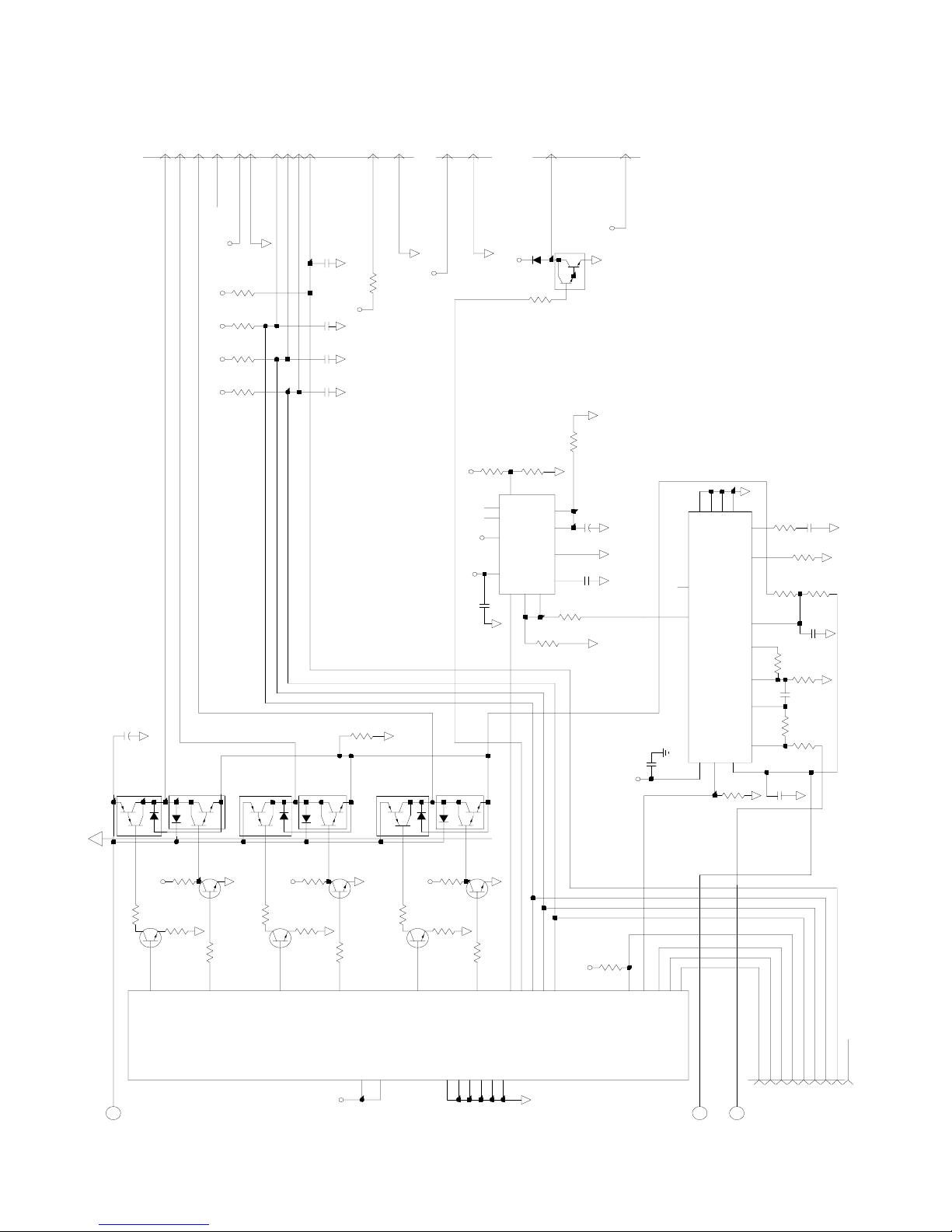
Through-Hole Power/Motor Board
Through-Hole Power/Motor Board
Through-Hole Power/Motor BoardThrough-Hole Power/Motor Board
Through-Hole Power/Motor Board
Through-Hole Power/Motor Board
Through-Hole Power/Motor BoardThrough-Hole Power/Motor Board
6
11
8
7
PIC 635
9
5
1
*
INDEX
NC
HALL SENSOR +5V
HALL SENSOR GND
+5V
R41
+5V
RP4
1
+5V
RP4
1
+5V
RP4
1
+5V
4
HALL 2
HALL 1
HALL 0
10K
1.5K
4
1.5K
1.5K
23
PIC 625
Q10
4
1
CRANK SENSOR
C21
.1
C17
.01
C16
.01
C20
.01
PIC 635
Q11
1
4
3
4
2
J6
MOTOR WHITE
MOTOR PURPLE
MOTOR ORANGE
C28
1200
+
2
PIC 625
Q8
4
Q9
1
1
10
12
CRANK SENSOR GND
CRANK SENSOR +12V
10
R42
+12V
R38
.05
3W
+12V
2
PIC 625
Q12
4
1
2
1
J8
FAN GND
FAN +12V
+12V
RP1
10K
2
1
+5V
11
7
TH
NC
6
NC
9
+
+12V
8
+
+12V
IN
1
C44
.01
PIC 635
Q13
1
4
LP6 Plus, LP10, and LP20 Technical Manual
3
J7
SOLENOID 1
CR11
C
Q20
1N4002
R45
4.75K
B
R43
10K4RP1
3
43
R1
+
C2
U7
12
2907N
GND
C18
2
C1
OUT
5
10
R40
4.75K
RP1
10K
6
5
1
SOLENOID +12V
+12V
E
TIP, NPN
47.5K
(4500RPM)
C19
1.0
.01
C43
+5V
Reference only
Reference only
Reference onlyReference only
13
10
4
7
E2
DT
GND
CTRT
11
NC
1
+1 C2
TL494
U9
CM 2 REF +2
1
CC
V
C1
E1
12
8
9
.01
10K
R48
(16 KHz)
C24
R54
150
5
6
14 16
R51
15
3
R50
2
.001
R53
75K
R58
R52
4.75K
681K
C23
.1
75K
R57
3.92K
C22
.01
1M
R49
39.2K
C37
.01
2
3
2
+5V
5
220
RP6
6
Q14
MPS6717
11
D2
22V BUS
B
Page 7-16
Page 7-16
Page 7-16Page 7-16
2
3
RP8
1
RP7
6
Q15
100
2
100
1K
RP5
1 2
15
D5
2
3
RP8
MPS6717
RP6
4
+5V
1
220
RP7
100
1
2
Q16
MPS6717
9
D0
U10
2732
(SOCKET)
2
2
3
100
3
2
1K
RP5
3
14 4
D4
+5V
3
Q18
MPS6717
3
220
RP6
4
Q17
+
A7
1
24
2
3
100
RP8
6
+5V
RP7
3
MPS6717
10
D1
22
Q19
MPS6717
5
100
4
6
RP1
1K
RP5
5
13
D3
A11CEOE
A10
A9
18
21
19
867
17
16
A0
A2
A1
D6
D7
GND
12
20
10K
8
7
345
+5V
2
23
*
BACKUP A8
CPU FORW A5
CPU OFFCPU A4
CPU SOLCPU A6
PWM OFFPW M A3
+ REG
A
*
*
CPU OFF
BACKUP
HALL 2
CPU SOL
CPU FWD
J5
9
8227
11
SPEED
C
NC
HALL 023CRANK SENSOR
HALL 1
6
21
24
November 2000
Page 89

LP6 Plus, LP10, and LP20 Technical Manual
Through-Hole Power/Motor Board
Through-Hole Power/Motor Board
Through-Hole Power/Motor BoardThrough-Hole Power/Motor Board
Reference only
Reference only
Reference onlyReference only
Through-Hole Power/Motor Board
Through-Hole Power/Motor Board
Through-Hole Power/Motor BoardThrough-Hole Power/Motor Board
November 2000
Page 7-17
Page 7-17
Page 7-17Page 7-17
Page 90
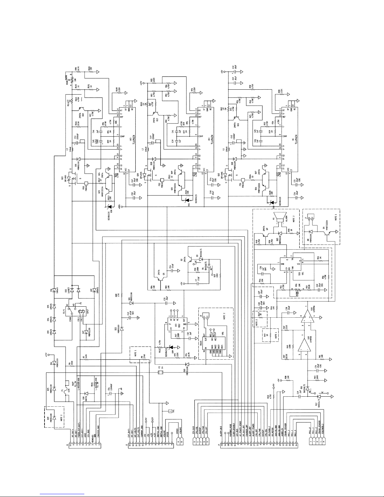
Surface-Mount Power/Motor Board
Surface-Mount Power/Motor Board
Surface-Mount Power/Motor BoardSurface-Mount Power/Motor Board
Surface-Mount Power/Motor Board
Surface-Mount Power/Motor Board
Surface-Mount Power/Motor BoardSurface-Mount Power/Motor Board
LP6 Plus, LP10, and LP20 Technical Manual
Reference only
Reference only
Reference onlyReference only
Page 7-18
Page 7-18
Page 7-18Page 7-18
November 2000
Page 91
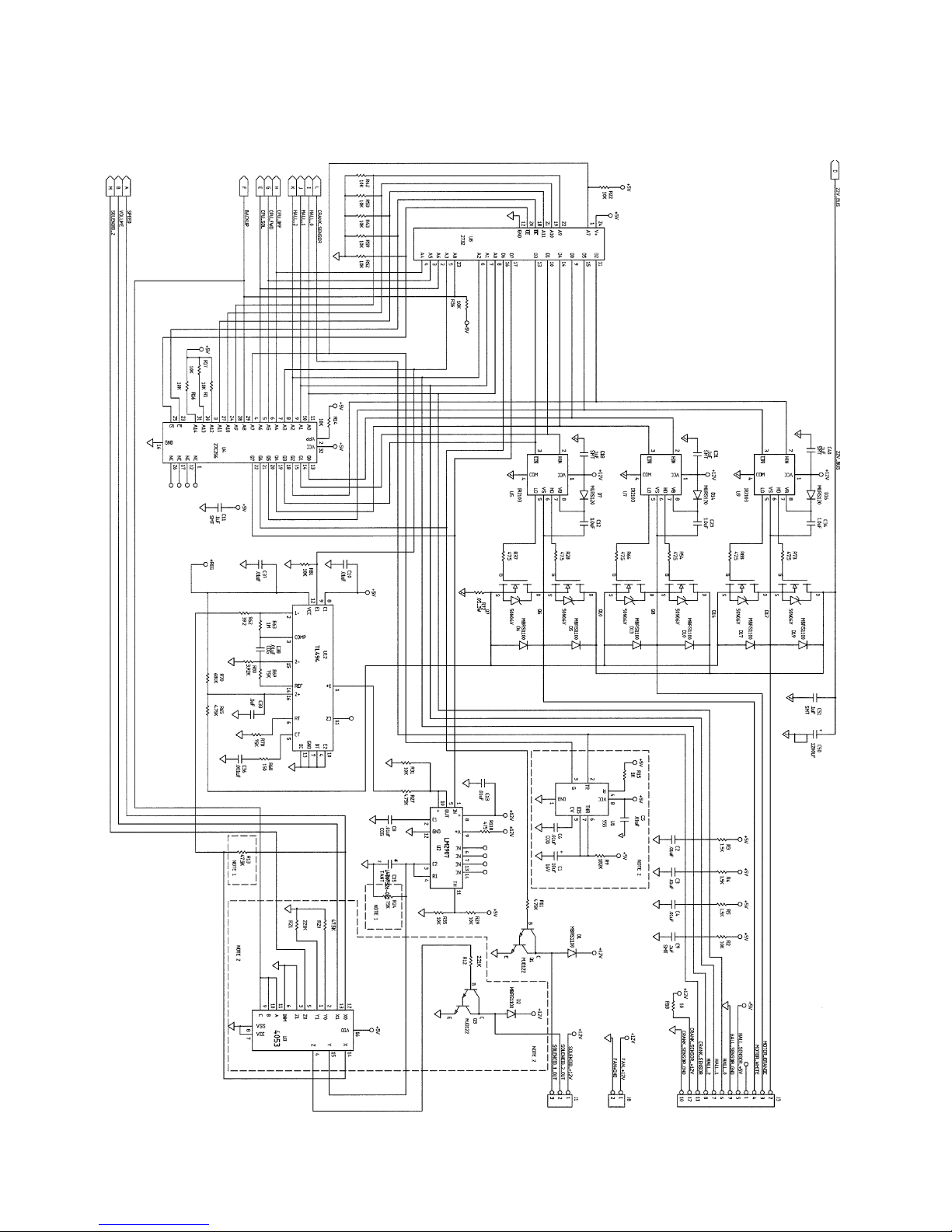
LP6 Plus, LP10, and LP20 Technical Manual
Surface-Mount Power/Motor Board
Surface-Mount Power/Motor Board
Surface-Mount Power/Motor BoardSurface-Mount Power/Motor Board
Surface-Mount Power/Motor Board
Surface-Mount Power/Motor Board
Surface-Mount Power/Motor BoardSurface-Mount Power/Motor Board
Reference only
Reference only
Reference onlyReference only
November 2000
Page 7-19
Page 7-19
Page 7-19Page 7-19
Page 92
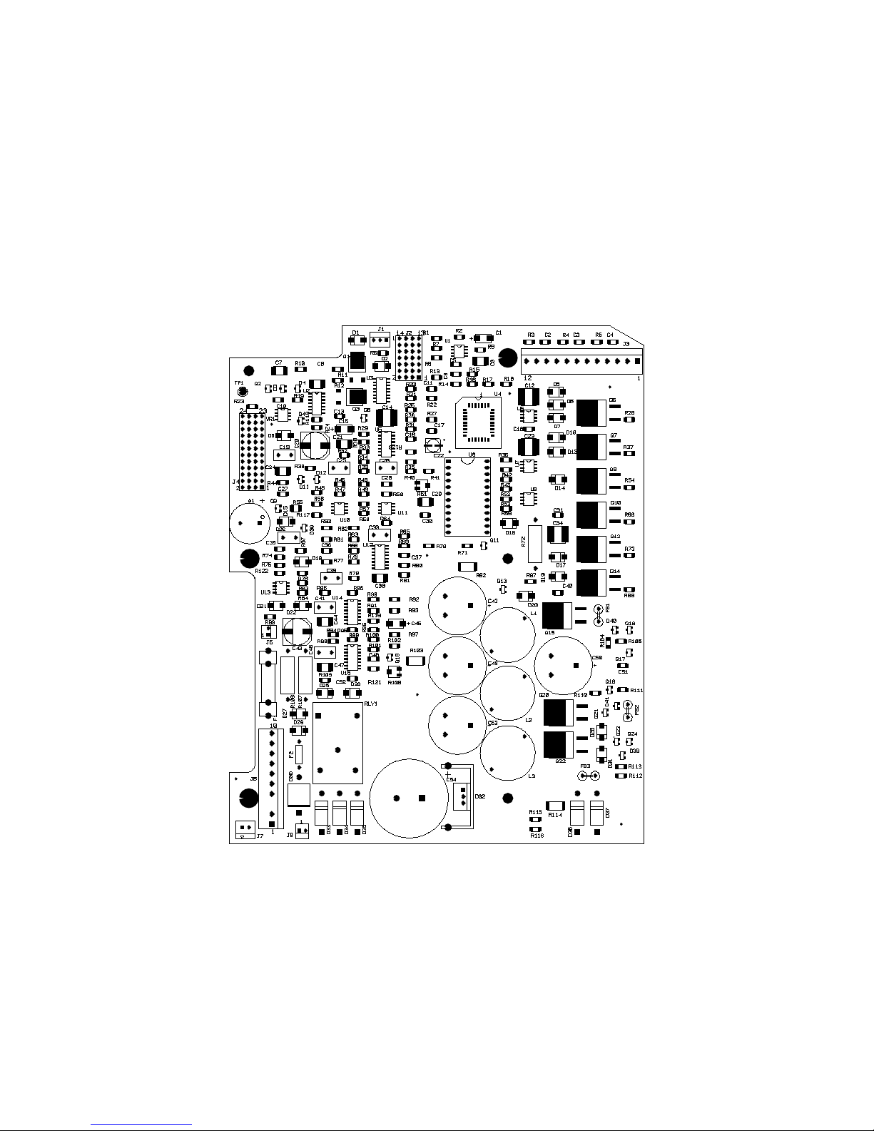
Surface-Mount Power/Motor Board
Surface-Mount Power/Motor Board
Surface-Mount Power/Motor BoardSurface-Mount Power/Motor Board
Surface-Mount Power/Motor Board
Surface-Mount Power/Motor Board
Surface-Mount Power/Motor BoardSurface-Mount Power/Motor Board
Reference only
Reference only
Reference onlyReference only
LP6 Plus, LP10, and LP20 Technical Manual
Page 7-20
Page 7-20
Page 7-20Page 7-20
November 2000
Page 93
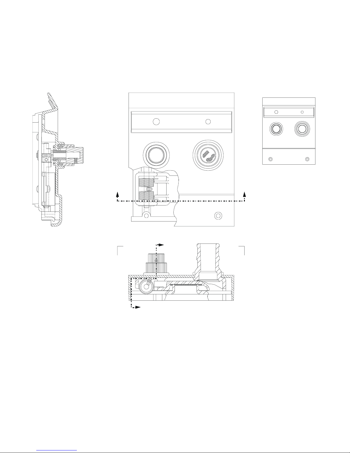
LP6 Plus, LP10, and LP20 Technical Manual
Pressure Limit Assembly (LP10, LP20)
Pressure Limit Assembly (LP10, LP20)
Pressure Limit Assembly (LP10, LP20)Pressure Limit Assembly (LP10, LP20)
Pressure Limit Assembly (LP10, LP20)
Pressure Limit Assembly (LP10, LP20)
Pressure Limit Assembly (LP10, LP20)Pressure Limit Assembly (LP10, LP20)
DETAIL C-C
SECTION A-A
B
A
C
A
B
C
Reference only
Reference only
Reference onlyReference only
November 2000
Page 7-21
Page 7-21
Page 7-21Page 7-21
Page 94
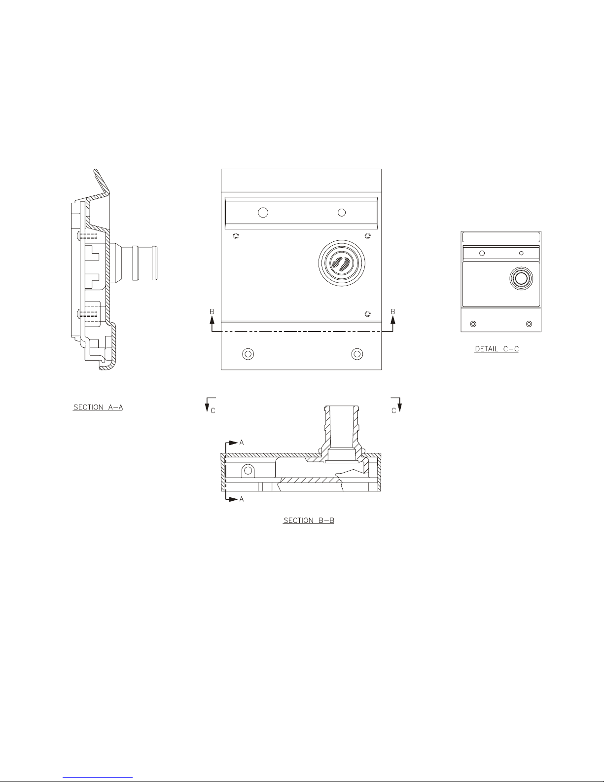
Front Bezel (LP6 Plus only)
Front Bezel (LP6 Plus only)
Front Bezel (LP6 Plus only)Front Bezel (LP6 Plus only)
Front Bezel (LP6 Plus only)
Front Bezel (LP6 Plus only)
Front Bezel (LP6 Plus only)Front Bezel (LP6 Plus only)
LP6 Plus, LP10, and LP20 Technical Manual
Page 7-22
Page 7-22
Page 7-22Page 7-22
Reference only
Reference only
Reference onlyReference only
November 2000
Page 95
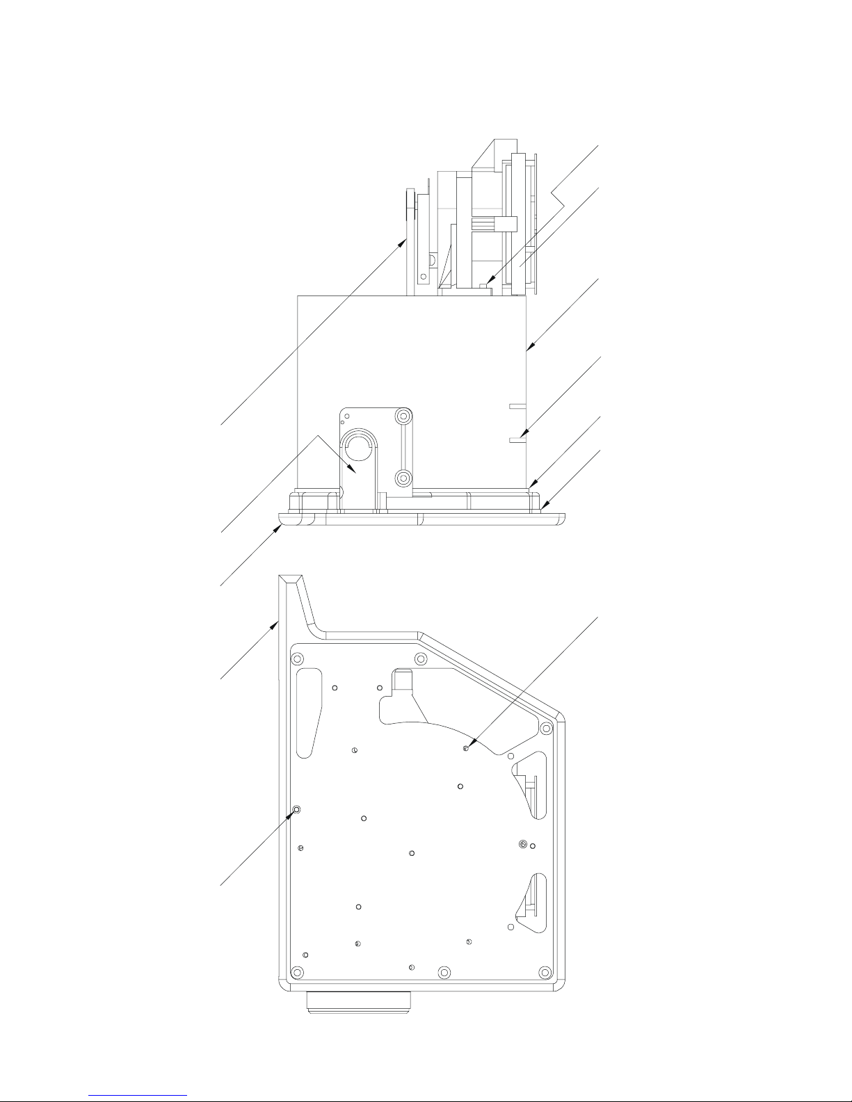
LP6 Plus, LP10, and LP20 Technical Manual
)
6
Right End Assembly
Right End Assembly
Right End AssemblyRight End Assembly
Right End Assembly
Right End Assembly
Right End AssemblyRight End Assembly
6-32 X 1/2 SHCS (4
MOTOR/GEARBOX ASSY.
CYLINDER
SERIAL # LABEL
PISTON ASSY.
MANIFOLD ASSY.
RIGHT END PLATE
RIGHT END PLATE
CYLINDER GASKET
MANIFOLD GASKET
6-32 X 1.25 SHCS (6)
-32 X 3/8 SHCS (10)
November 2000
Page 7-23
Page 7-23
Page 7-23Page 7-23
Page 96

Back Panel (LP6 Plus, LP10)
Back Panel (LP6 Plus, LP10)
Back Panel (LP6 Plus, LP10)Back Panel (LP6 Plus, LP10)
Back Panel (LP6 Plus, LP10)
Back Panel (LP6 Plus, LP10)
Back Panel (LP6 Plus, LP10)Back Panel (LP6 Plus, LP10)
8
BLUE
(TBI)
BLK 1
7 BLUE
7
FUSED EXT BATT (+)
6A
EXT BATT (+) UNFUSED
1
10
N.U.
EXT BATT (-)
3
O2
G
INTERNAL BATT
P3
ASSY.
TRANSFORMER
CHASSIS GND
4
3
2
1
KEY
GND
60 MZ
BLUE
YEL 5
(SPLICE)
GRN/YEL
6
4
ORG
5
FW RECT
16 VAC
+
-
2
3
BRN
RED
2
3
SW
SEL.
VOLT
4
1
BRN
BLUE
LOAD
LINE
FILTER
LINE
V
BRN
1A
1A
BRN
BLUE
1
2
3
INTERNAL BATT (+)
P2-1
RED
LP6 Plus, LP10, and LP20 Technical Manual
6
9
INTERNAL BATT (-)
Reference only
Reference only
Reference onlyReference only
CABLE
PRINTER
P2-2
BLK
-
+
PORT
COMM.
REMOTE
6-32 X 3/8
SHCS (4)
8-32 X 3/4
ALARM
CONNECTOR
GROUND
SHCS (2)
12V
CIRCUIT
BREAKER
BATTERY
EXTERNAL
CONNECTOR
STUD
CORD
RETAINER
SCREEN
BLK
PLUG
(P1)
WHT
(REF)
BATT
EXT.
BAIL
LOCK
BLUE LOCTITE 425
8-32 X 3.5 FHCS (4),
TRANSFORMER SCREWS
ON/OFF
SWITCH
4-40 X 3/16 SHCS
110/220V SWITCH,
(2), BLUE LOCTITE 242
RELIEF
STRAIN
CORD
POWER
CORD
WRAP
FEET (4)
Page 7-24
Page 7-24
Page 7-24Page 7-24
November 2000
Page 97
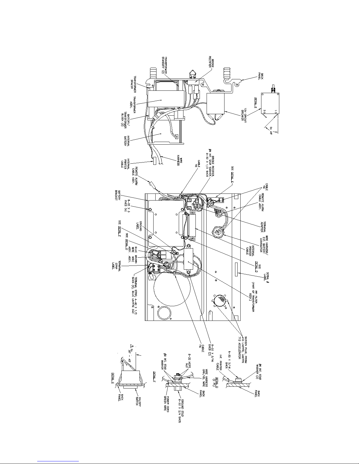
LP6 Plus, LP10, and LP20 Technical Manual
Back Panel (LP6 Plus, LP10)
Back Panel (LP6 Plus, LP10)
Back Panel (LP6 Plus, LP10)Back Panel (LP6 Plus, LP10)
Reference only
Reference only
Reference onlyReference only
Back Panel (LP6 Plus, LP10)
Back Panel (LP6 Plus, LP10)
Back Panel (LP6 Plus, LP10)Back Panel (LP6 Plus, LP10)
November 2000
Page 7-25
Page 7-25
Page 7-25Page 7-25
Page 98
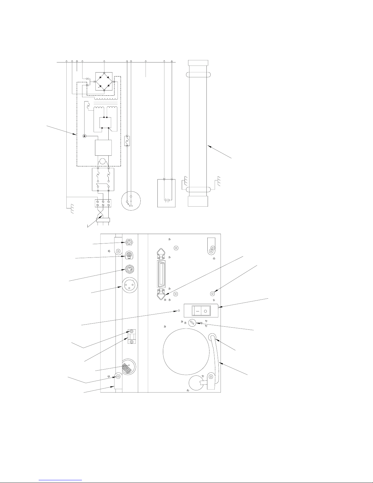
Back Panel (LP20)
Back Panel (LP20)
Back Panel (LP20)Back Panel (LP20)
Back Panel (LP20)
Back Panel (LP20)
Back Panel (LP20)Back Panel (LP20)
6
4
ORG
VOLT
BRN
BRN
1A
GRN/YEL
3
BLK
GRN
5
FW RECT
16 VAC
+
7 BLUE
2
3
BLK 1
BRN
RED
SEL.
4
1
BLUE
LOAD
LINE
FILTER
LINE
V
BLUE
1A
BRN
BLUE
1
2
(TBI)
WHT
(P1)
P3
CHASSIS GND
ASSY.
TRANSFORMER
4
3
2
1
KEY
GND
60 MZ
BLUE
YEL 5
(SPLICE)
FUSED EXT BATT (+)
6A
EXT BATT (+) UNFUSED
1
LP6 Plus, LP10, and LP20 Technical Manual
9
8
7
10
N.U.
EXT BATT (-)
3
O2
G
(REF)
BATT
EXT.
6
Reference only
Reference only
Reference onlyReference only
INTERNAL BATT (+)
INTERNAL BATT (-)
CABLE
PRINTER
P2-1
BLK P2-2
RED
-
+
INTERNAL BATT
COMM.
PORT
NURSE CALL
ALARM
REMOTE
CABLE
CONNECTOR
SHCS (2)
6-32 X 3/8
SHCS (4)
8-32 X 3/4
12V
CONNECTOR
EXTERNAL
STUD
GROUND
CORD
RETAINER
CORD
WRAP
FEET (4)
CIRCUIT
BREAKER
BATTERY
CONNECTOR
PLUG
SCREEN
BAIL
RELIEF
STRAIN
LOCK
110/220V SWITCH,
CORD
POWER
BLUE LOCTITE 425
8-32 X 3.5 FHCS (4),
TRANSFORMER SCREWS
ON/OFF
4-40 X 3/16 SHCS
(2), BLUE LOCTITE 242
SWITCH
Page 7-26
Page 7-26
Page 7-26Page 7-26
November 2000
Page 99
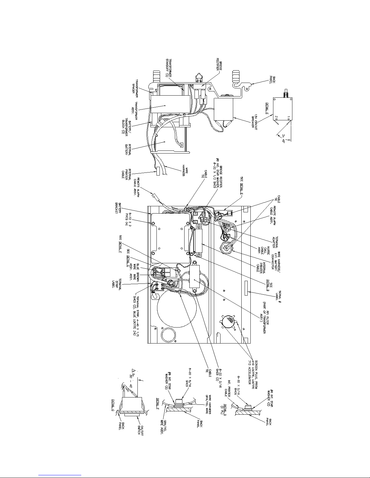
LP6 Plus, LP10, and LP20 Technical Manual
Back Panel (LP20)
Back Panel (LP20)
Back Panel (LP20)Back Panel (LP20)
Reference only
Reference only
Reference onlyReference only
Back Panel (LP20)
Back Panel (LP20)
Back Panel (LP20)Back Panel (LP20)
November 2000
Page 7-27
Page 7-27
Page 7-27Page 7-27
Page 100
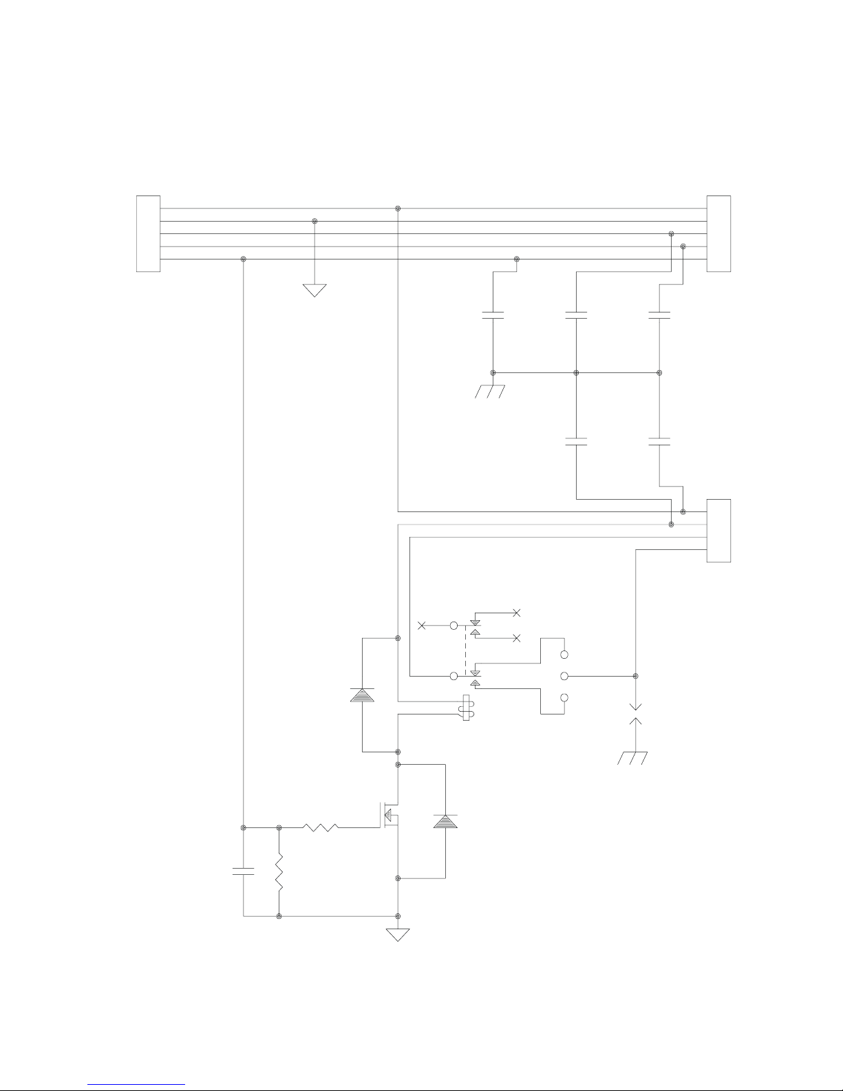
Nurse Call Board
Nurse Call Board
Nurse Call BoardNurse Call Board
Nurse Call Board
Nurse Call Board
Nurse Call BoardNurse Call Board
LP6 Plus, LP10, and LP20 Technical Manual
P1
1
2
3
4
5
C6
+8 V
RESET
VISUAL
AUDIO
C3
C5
0.01u
P2
1
2
3
4
5
C2
0.01u0.01u 0.01u
C4
0.01u
P3
1
2
3
4
0.01u
C1
1N4004
R2
10k
R1
100k
D1
BS170
Q1
10
K1
8
3
1
9
7
2
4
TQ2E-9V
D2
1N4004
JP1
JP2
SG1
GL-75L
Reference only
Reference only
Reference onlyReference only
Page 7-28
Page 7-28
Page 7-28Page 7-28
November 2000
 Loading...