


Page 1
357 Beloit Street, P.O. Box 457, Burlington, WI 53105-0457 U.S.A. Phone 262/763-3591 FAX 262/763-2881
Email: nelsales@nelfc.com
www.nelfc.com
TTL Compatible Enable/Disable
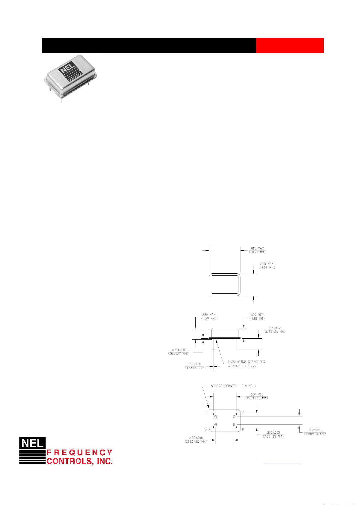
HS-1200/1210 Series
Description
The HS-1200/1210 Series of quartz crystal oscillators provide enable/disable 3-state TTL compatible
signals for bus connected systems. Supplying Pin 1 of the HS-1200 units with a logic “0" enables the output
on Pin 8. Alternately, supplying pin 1 of the HS-1210 units with a logic “1" enables its Pin 8 output. In the
disabled mode, Pin 8 presents a high impedance to the load. All units are resistance welded in an all metal
package, offering RFI shielding, and are designed to survive standard wave soldering operations without
damage. Insulated standoffs to enhance board cleaning are standard.
Features
• Wide frequency range– 0.5MHz to 36MHz
• User specified tolerance available
• Will withstand vapor phase temperatures of 253°C
for 4 minutes maximum
• Space-saving alternative to discrete component
oscillators
• High shock resistance, to 3000g
• All metal, resistance weld, hermetically sealed
package
• Low Jitter
• High Q Crystal actively tuned oscillator circuit
• Power supply decoupling internal
• No internal PLL avoids cascading PLL problems
• Low power consumption
• Gold plated leads - Solder dipped leads available
upon request
Electrical Connection
Pin Connection
1 Enable Input
7 Grd & Case
8 Output
14 V
CC
Dimensions are in inches and (MM)
CRYSTAL CLOCK OSCILLATORS
Data Sheet 8706A
Rev. M
Page 2
357 Beloit Street, P.O. Box 457, Burlington, WI 53105-0457 U.S.A. Phone 262/763-3591 FAX 262/763-2881
Email: nelsales@nelfc.com
www.nelfc.com
HS-1200/-1210 Series Continued
TTL Compatible - Enable/Disable
Operating Conditions and Output Characteristics
Electrical Characteristics
Parameter Symbol Conditions Min Typical Max
Frequency ----- ----- 0.5MHz ----- 36.0MHz
Duty Cycle ----- @ VCC/2 40/60% ----- 60/40%
Logic 0 VOL @ 16mA ----- ----- 0.4V
Logic 1
VOH @ 0.4mA 2.4V ----- ----Rise & Fall Time tr,tf @ 0.4 to 2.4V ----- ----- 5 ns
Tpz ----- ----- ----- ----- 25 ns
Enable/Disable 1K internal pullup
Logic High Voltage ----- to V
CC
2.4V 2.0V ----Enable/Disable
Logic Low Voltage ----- -5.5mA I
IL
----- 0.2V 0.4V
Jitter, RMS
(2)
----- ----- ----- ----- 8 psec
Frequency Stability
(1)
dF/F Overall conditions including: -100ppm ----- +100ppm
voltage, calibration, temp.,
10 yr aging, shock, vibration
General Characteristics
Parameter Symbol Conditions Min Typical Max
Supply Voltage VCC ----- 4.5V 5.0V 5.5V
Supply Current ICC No Load 0.0 mA ----- 55 mA
Output current IO ----- 0.0 mA ----- ±16.0 mA
Operating temperature TA ----- 0°C ----- 70°C
Storage temperature TS ----- -55°C ----- 125°C
Power Dissipation P
D
----- ----- ----- 303 mW
Lead temperature TL Soldering, 10 sec. ----- ----- 300°C
Load ---- ----- ----- ----- 10TTL gate
Start-up time t
S
<20MHz ----- ----- 2 ms
20MHz or greater ----- ----- 10 ms
Environmental and Mechanical Characteristics
Mechanical Shock Per MIL-STD-202, Method 213, Condition E
Thermal Shock Per MIL-STD-833, Method 1011, Condition A
Vibration 0.060" double amplitude 10 Hz to 55 Hz, 35g’s 55Hz to 2000 Hz
Soldering Condition 300°C for 10 seconds
Hermetic Seal Leak rate less than 1 x 10 -8 atm.cc/sec of helium
Footnotes:
1) Standard frequency stability (±20,±25,±50ppm & others available)
2) Jitter performance is frequency dependent. Please contact factory for full characterization.
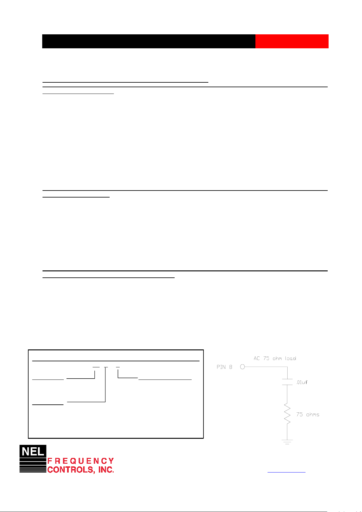
Test Load:
Rev. M
CRYSTAL CLOCK OSCILLATORS
HS - X120X - FREQ
Package Code
Tolerance/Performance
HS Leaded 4 pin (14 pin) 0 ±100ppm 0-70°C
SM Leaded 4 pin (14 pin) SMD 1 ±50ppm 0-70°C
Gull Wing 7 ±25ppm 0-70°C
Input Voltage
9 Customer Specific
Code Specification A ±20ppm 0-70°C
A 3.3V B ±50ppm -40 to +85°C
5V C ±100ppm -40 to +85°C
Creating a Part Number
Data Sheet 8706A