

Page 1
4420064 – Rev. 1801
KIMO
INSTRUCTION MANUAL
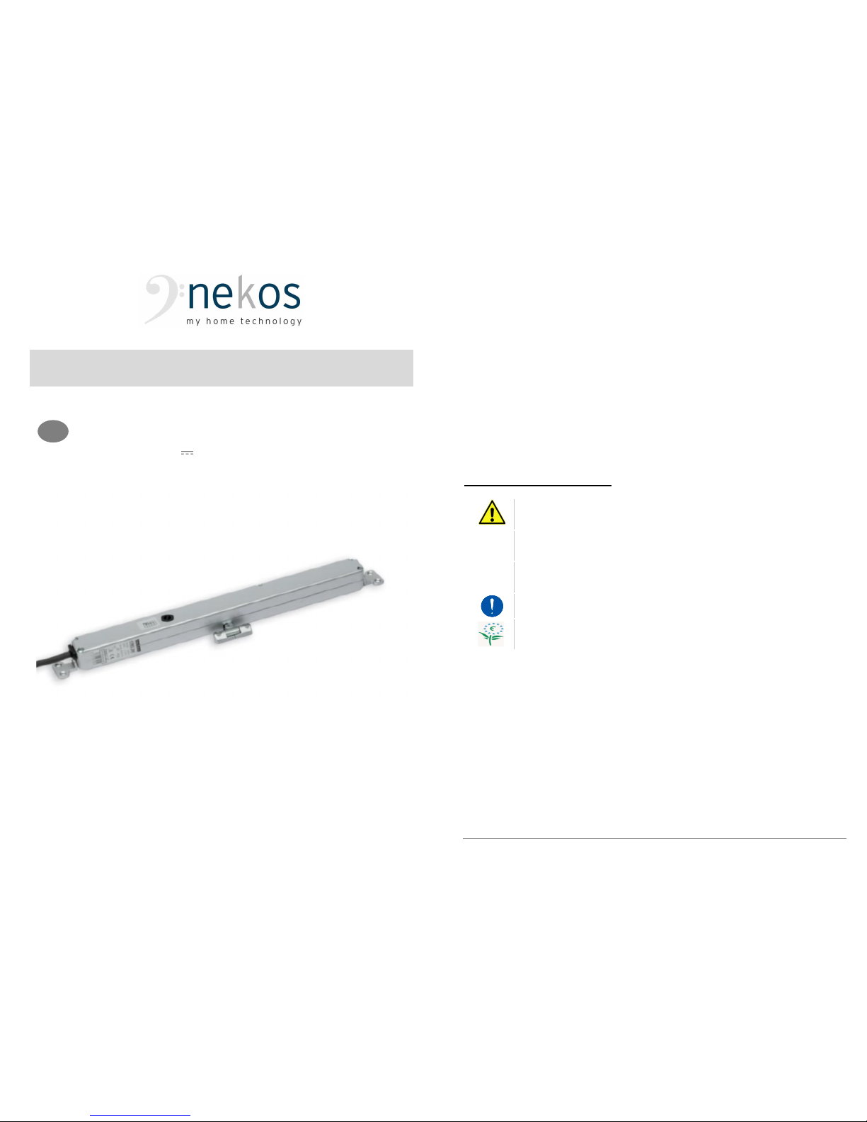
CHAIN ACTUATOR
Force 200N – Maximum stroke 210 mm
Electrical feeding 24V
EN
2
nekos products have been manufactured in accordance with safety standards and conforms to the
stipulations of current standards in force.
When correctly assembled, installed and used according to the present instructions, they will not
generate any danger for persons, animals or items.
Symbols used in the manual
DANGER
This indication draw the attention about potential
dangers for safety and health of peoples and animals.
INFORMATION This information give further suggestions.
ATTENTION
This indication draw the attention about potential
dangers for the product itself.
WARNING
This indication draw the attention about potential
damages to goods.
ENVIRONMENTAL
INSTRUCTION
Environmental indication draw the attention about
potential dangers for the environment.
Page 2
3
Contents
1. Security rules ................................................................................................................ 4
2. Technical operating information ..................................................................................... 5
3. Formulas and recommendations for installation ............................................................ 5
3.1. Calculation of opening / closure force .................................................................. 5
3.2. Maximum opening based on sash height ............................................................. 6
4. Construction and regulatory references ......................................................................... 6
5. Technical data ............................................................................................................... 7
6. Id plate and marking data .............................................................................................. 8
7. Electric power supply .................................................................................................... 8
7.1. Selecting the cross-section of the power supply cables ........................................ 8
8. Electrical connection ..................................................................................................... 8
9. Instructions for assembly ............................................................................................... 9
9.1. Preparation for mounting the actuator ................................................................ 10
9.2. Recessed mounting .......................................................................................... 10
9.3. Surface mounting on top-hung windows opening outwards or bottom-hung
windows .................................................................................................................. 10
10. Programming the actuator ........................................................................................... 11
10.1. Opening stroke-end ........................................................................................... 11
10.2. Closure stroke-end ............................................................................................ 11
10.3. Operation with BK-LOCK electromechanical lock .............................................. 12
11. Actuator kit with electromechanical lock ....................................................................... 12
11.1. Electrical connection and operating logic ........................................................... 12
11.2. Sound diagnostics in case of anomaly ............................................................... 13
12. Checking for correct assembly .................................................................................... 13
13. Emergency manoeuvres, maintenance or cleaning ...................................................... 13
14. Troubleshooting .......................................................................................................... 13
15. Environmental protection ............................................................................................. 14
16. Certificate of guarantee ............................................................................................... 14
17. Declaration of incorporation (for a partly completed machine) and EC Declaration of
Conformity .................................................................................................................. 15
4
1. Security rules
PLEASE
NOTE:
IMPORTANT
SAFETY
INSTRUCTIONS.
CAREFULLY
OBSERVE ALL THE FOLLOWING INSTALLATION INSTRUCTIONS TO ENSURE
PERSONAL SAFETY. IMPROPER INSTALLATION CAN SERIOUSLY ENDANGER SAFETY.
K
EEP THESE INSTRUCTIONS AFTER INSTALLATION
.
MANDATORY RISK ANALYSIS AND PROTECTION MEASURES
.
The Nekos electrical actuators comply with the Machinery Directive (2006/42/EC),
Standard IEC 60335-2-103 (Particular requirements for drives for gates, doors and
windows) and other directives and regulations indicated in the attached Declarations
of Incorporation and CE Conformity (at the end of the manual). According to the
Machinery Directive, actuators are “partly completed machinery” intended for
incorporation into doors and windows. The manufacturer/supplier of the window is
required, with exclusive responsibility, to ensure the compliance of the entire system
with the applicable standards and to issue CE certification. We strongly discourage
any use of the actuators other than that specified and therefore, in any case, the
supplier of the complete system retains full liability.
For systems installed at a height of less than 2.5 m above floor level or other levels
accessible to users, the manufacturer/supplier of the window must conduct risk
analysis regarding potential harm (violent blows, crushing, wounds) caused to
people by normal use or possible malfunction or accidental breakage of the
automated windows, and to implement suitable protective measures in view of
these. Such measures include those recommended by the specified standard:
- controlling the actuators via a “deadman’s button” placed near the system and
within the operator’s field of view, to ensure that people are out of the way during
operation. The button should be placed at a height of 1.5 m and operated by key
if accessible to the public; or:
- use of contact safety systems (also included in the actuators) that ensure a
maximum closing force of 400/150/25 N, measured in accordance with
paragraph BB.20.107.2 of IEC 60335-2-103; or:
- use of non-contact safety systems (lasers, light grids); or:
- use of fixed safety barriers that prevent access to moving parts.
Automated windows are deemed adequately protected if they:
- are installed at a height of >2.5 m; or:
- have a leading-edge opening of <200 mm and a closing speed of <15 mm/s; or:
- are part of a smoke and heat evacuation system for emergency use only.
In any case, moving parts of windows that could fall below 2.5 m following breakage
of a system component need to be fixed or secured in order to prevent them from
suddenly falling or collapsing: e.g. the use of safety arms on bottom-hung windows.
The device is not intended for use by persons (including children) with
reduced physical, sensory or mental capabilities, or lacking experience and
knowledge. Do not allow children to play with the fixed controls and keep any
remote
-
control units out of their reach.
The actuator is destined exclusively for installation indoors. For any special
application we recommend you consult the manufacturer beforehand.
Page 3
5
After removing packaging, check for any damage on the appliance.
MAINTENANCE and REPAIRS
Periodically check the installation by inspecting the cables, springs, rods and
mechanical parts for wear or damage. Do not use if repair or adjustment is
required.
Disconnect the power supply during cleaning or maintenance operations.
Do not use solvents or jets of water to wash the appliance. The appliance
should not be submerged in water.
In the event of breakage or malfunction, switch the appliance off at the
general switch and call for the services of a qualified technician.
Repairs should only be performed by qualified personnel at assistance
centres authorised by the manufacturer.
Always request exclusive use of original spare parts. Failure to respect this
condition could compromise safety and invalidate the benefits contained in
the warranty for the appliance.
In the event of any problems or queries, consult your agent or contact the
manufacturer directly.
2. Technical operating information
The chain actuator is used to open and close the window by means of a three-link
steel chain (Nekos Patent). The movement is achieved with very low-voltage (24V
SELV) electricity that powers a gear motor controlled by a functional electronic
device. Window opening can be programmed, and the device allows excursion of
the chain to strokes of 70, 125, 170 and 210 mm. For the return stroke, i.e., the
closing of the window, the stroke-end is determined by an electronic process that
automatically calculates the required power absorption to produce the movement of
the window, and therefore no settings are required. The actuator can also be
installed without the immediate availability of electricity for window movement; in this
case the actuator will simply hold the window closed after assembly. The structure of
the actuator is entirely metal and it is used for room ventilation. The coupling
between the actuator and support brackets fixed to the window frame is a quickconnect coupling that allows the actuator to rotate in order to adapt to the stroke of
the chain, even on windows with reduced height. The brackets are fixed to the frame
during actuator assembly with just two screws. Combined with the BK-LOCK
product and perimeter fittings, it constitutes the security lock that keeps the window
closed tight and guarantees a high thermal K.
3. Formulas and recommendations for installation
3.1. Calculation of opening / closure force
Using the formulas on this page, approximate calculations can be made for the force
required to open or close the window considering all the factors that determine the
calculation.
6
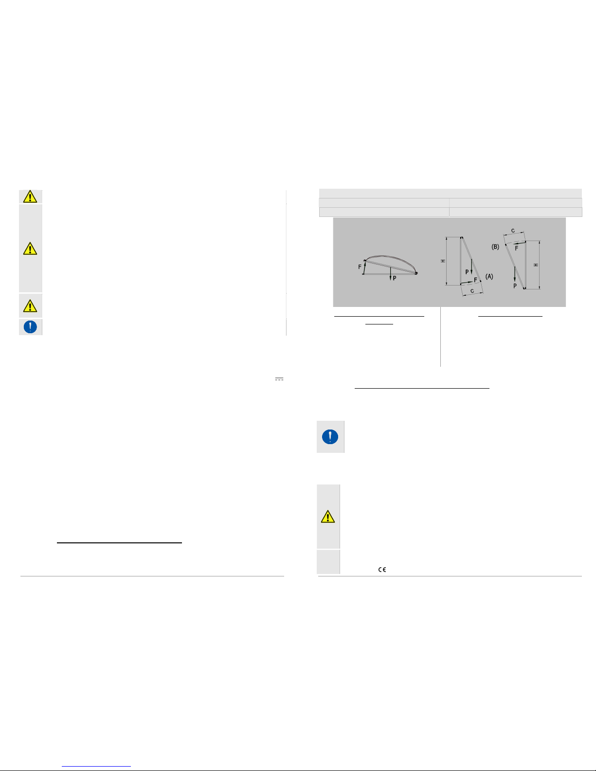
Symbols used for the calculation
F (Kg) = Force for opening or closing
P (Kg) = Weight of the window (mobile sash only)
C (cm) = Opening stroke (actuator stroke) H (cm) = Height of the mobile sash
For horizontal light domes or
skylights
F = 0,54 x P
(Eventual weight of snow or wind on the
cupola should be calculated separately).
For vertical windows
TOP HUNG WINDOWS, OUTWARD OPENING
(A)
BOTTOM HUNG WINDOWS
(B)
F = 0,54 x P x C : H
(Eventual load of favourable or unfavourable wind
on the sash should be calculated separately).
3.2. Maximum opening based on sash height
The selection of the actuator stroke should be made based on the height of the sash
and its application. As a general rule, never select a stroke greater than the height of
the window frame; select the stroke directly below it.
W
ARNING
. The actuator is designed to be recess mounted on the window
frame. Check that during the stroke the chain does not touch the profile of
the sash, there are no obstacles to opening the window and the chain does
not push against the window frame.
4. Construction and regulatory references
INTENDED USE
The KIMO chain actuator is designed and built to open
and close top-hung windows opening outwards, bottom-hung windows or
up-and-over roof windows. Its use is specifically intended for ventilation, air
conditioning of rooms and, if used in combination with the BK-LOCK window
lock, also as a building security system; it is highly recommended that the
actuator not be used for any other purpose unless approved by the
manufacturer beforehand, with the supplier of the entire system in any case
retaining sole liability.
The actuator is manufactured in accordance with the EC Directives and
Regulations listed in the attached Declaration of Incorporation and
Conformity .
Page 4
7
Electrical connections must conform to regulations in force for the design
and set up of electrical equipment.
To ensure efficient separation from the grid, an approved type of bipolar
“dead-man” switch should be used. An omnipolar general power switch with
minimum distance of 3 mm between contacts should be installed upstream of
the control line.
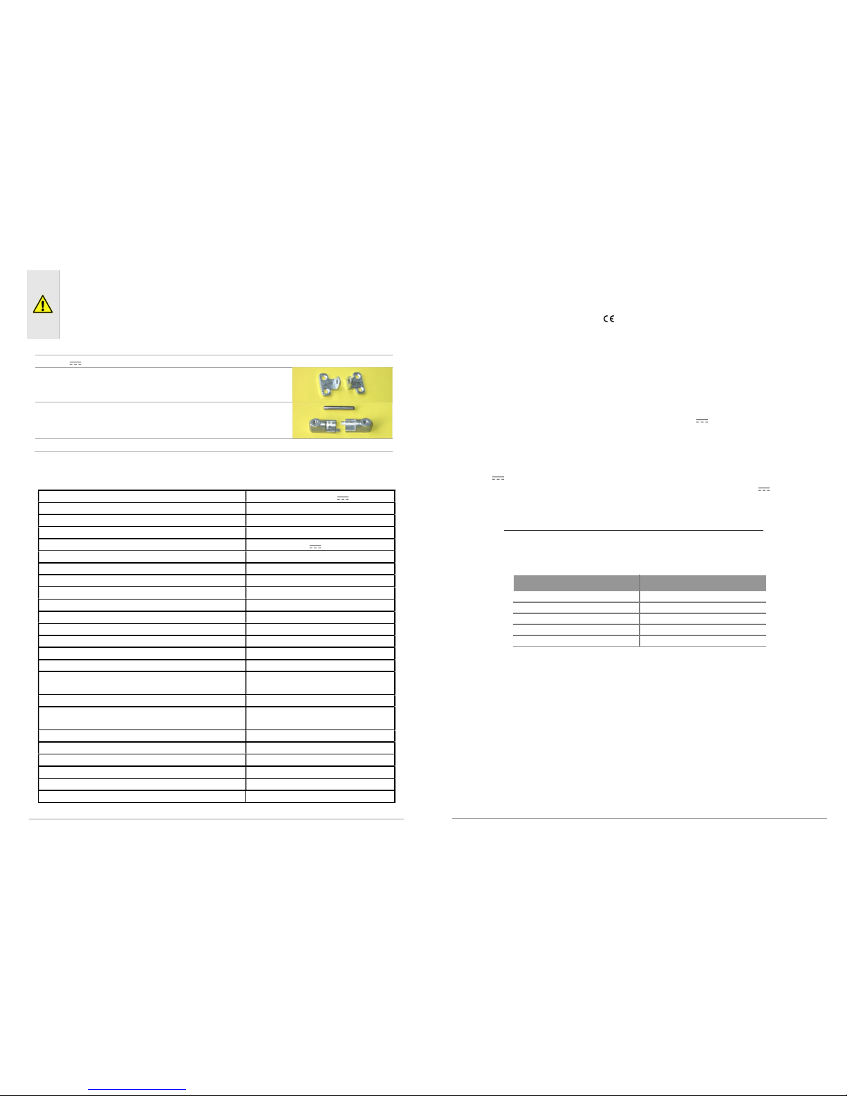
The actuator is individually packaged in a cardboard container and each pack contains:
24V electrical actuator complete of connector for feeding cable wiring.
2 support brackets
2 half-brackets for attach to the frame, complete with
pin
Instruction manual
5. Technical data
Model
KIMO 24V
Force exerted by thrust 100N
Force exerted by traction 200N
Strokes (can be selected at any time) 70, 125, 170, 210 mm
Power supply voltage 24 V SELV
Rated absorbed current 0,36 A
Power absorbed at nominal load 8,6 W
Electrical insulation Class III
No load speed 5,5 mm/s
Duration of no load stroke (210 mm) 38 s
Type of service S2 of 3 min
Operating temperature - 5 + 65 ºC
Protection index for electrical devices IP32
Adjustment of connection to window frame Automatic definition of position
Parallel powering of two or more motors YES (max 20 actuators)
Operation with BK-LOCK electromechanical
lock
Yes
Synchronised function Not foreseen
Holding nominal force (it can vary according to
the chosen brackets)
1.700N
Stroke-end at opening Electronic by dip-switch
Stroke
-
end at closing
At absorption of po
wer
Chain exit Central
Length of power cable 2 m
Dimensions 29x29x310 mm
Weight 0,720 Kg
The data indicated in these figures is not binding and is subject to variation without notification.
8
6. Id plate and marking data
The Machine Directive classifies actuators as “partly completed machinery” and they
are supplied with a Declaration of Incorporation, attached to this booklet; with regard
to the electrical side, they bear marking and come under the LVD and CEM
Directives and the other Regulations listed in the attached Declaration of Conformity.
With this marking, the actuators can be sold and used throughout the European
Union with no further requirements. The plate data is displayed on an adhesive label
placed on the outside of the container, printed in black on a grey background.
7. Electric power supply
The KIMO actuator is powered with a voltage of 24V SELV. The power supply
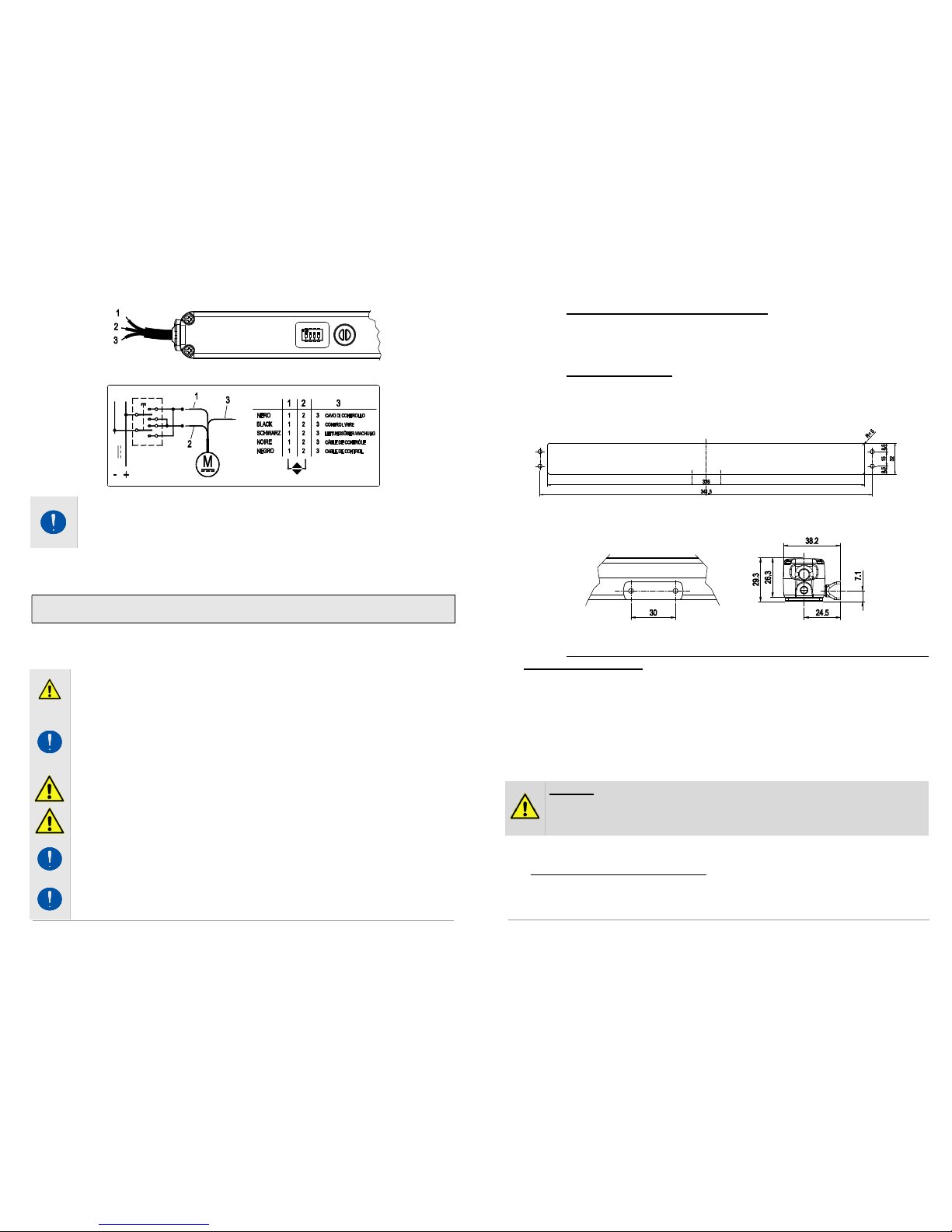
cable has three conductors: the first conductor BLACK “1” that should be connected
to the + (positive) CLOSES the window; the second conductor Black “2” that should
be connected to the + (positive) OPENS the window; the third conductor Black “3” is
the conductor used for the BK-LOCK control communication signal.
The 24V low-voltage actuators can be powered using a station with emergency
batteries or a security power supply unit with an output voltage of 24V (min. 20.4V,
max. 28,8V), that is to say, sized based on the number of actuators connected.
7.1. Selecting the cross-section of the power supply cables
It is necessary to check the cross-section of the cable, which should be calculated
based on the length of the cable itself. The table below specifies the maximum length
of the cables for connection of a motor.
Cable section Max cable length
4,00 mm²
~ 270 m
2,50 mm²
~ 170 m
1,50 mm²
~ 100 m
0,75 mm²
~ 50 m
0,50 mm²
~ 35 m
8. Electrical connection
The machines are equipped with a power supply cable constructed in compliance
with safety standards and restrictions on radio-frequency interference.
The power supply cable - with conductors having a cross-section of 0.5 mm² - must
be wired to a special connector as shown in the diagram below, in the following
sequence:
1 – BLACK-coloured conductor, marked “1”;
2 – BLACK-coloured conductor, marked “2”;
3 – BLACK-coloured conductor, marked “3”:
Page 5
9
For harness, please follow this diagram:
Note: the first conductor
B
LACK
“1”
that should be connected to the +
(positive) C
LOSES
the window; the second conductor Black “2” that should be
connected to the + (positive) O
PENS
the window; the third conductor Black
“3” is the conductor used for the BK-LOCK control communication signal.
9. Instructions for assembly
These indications are for specialised technical personnel and basic work and
safety techniques are not indicated.
All preparatory, assembly and electrical connection operations must be performed
by specialised technical personnel to guarantee optimal function and service of the
actuator. Check that the following fundamental conditions have been met:
Before installing the actuator, check that the moving parts of the window on
which it is to be installed are in perfect working condition and that they
open and close properly and are well balanced (where applicable).
Actuator specifications must be sufficient for movement of the window
without encountering any obstacle. The limits indicated in the technical data
table must not be superseded (page 7) and the most appropriate stroke
should be selected. Calculations should be checked using the formula
indicated on page 6.
Attention. Check that the electrical power supply corresponds to that
indicated on the
TECHNICAL DATA
label on the machine.
Ensure that the actuator has not been damaged during transport, first
visually and then by powering in both directions.
Check that the width of the inside of the window (where the actuator is to
be assembled) is over 360 mm, otherwise the actuator should not be
installed.
Check that once the actuator has been installed, chain completely in, the
window is perfectly closed. If this is not the case the actuator will not
function correctly as the window will not close correctly.
24V
10
9.1. Preparation for mounting the actuator
Before beginning to mount the actuator, depending on the type of application, the
window frame must be prepared by carrying out the following operations:
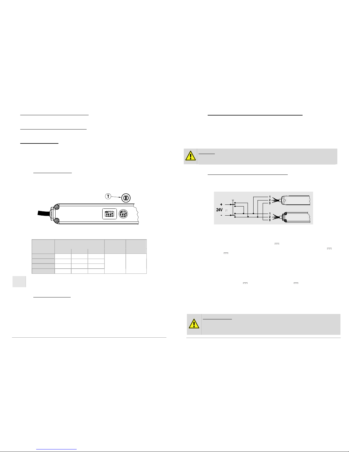
9.2. Recessed mounting
For recessed mounting, the window frame must be prepared by milling and making
two holes as indicated in the diagram below. The depth of the milling must be at
least 30 mm.
Then make two Ø4.5 holes on the sash for the attachment bracket. The
measurements are specified in the diagram below.
9.3. Surface mounting on top-hung windows opening outwards or
bottom-hung windows
The actuator can also be surface mounted on top-hung windows opening outwards or
dormer windows and on bottom-hung windows, however for these specific applications
special support brackets are required for the actuator which must be supplied
separately. The two half-brackets attaching the actuator to the sash, however, are the
same standard brackets supplied with the actuator and included in the package. To
prepare the holes on the window frame and sash, use the drilling template included in
the package of the special brackets; this template also specifies the diameter of the
holes and their position in reference to the inner edge of the window frame.
Warning. In order to prevent unpleasant mishaps with the machine and
possible safety hazards, carefully choose the length of the clamping screws
in order to avoid damaging the power supply cables during the mounting
procedure.
In order to carry out a cost-effective and precise up-to-standard work, it is best if you
prepare the following complementary material: small parts, equipment and tools.
Fastening on metal window frames: M4 threaded inserts (2 pieces for recessed
mounting and 4 pieces for surface mounting), M4x12 flat head metric screws (2
pieces (4 pieces for surface mounting)).
Page 6
11
Fastening on wooden window frames: Ø4 self-threading wood screws (2 pieces
for recessed mounting and 4 pieces for surface mounting), with an appropriate
length for the type of window frame.
Fastening on PVC window frames: Ø3.9x13 self-threading metal screws (2
pieces for recessed mounting and 4 pieces for surface mounting), with an
appropriate length for the type of window frame.
Equipment and tools: tape-measure, pencil, drill/electric screwdriver, set of drill
bits for metal, insert for screwing in, electrician's scissors, screwdrivers.
10. Programming the actuator
10.1. Opening stroke-end
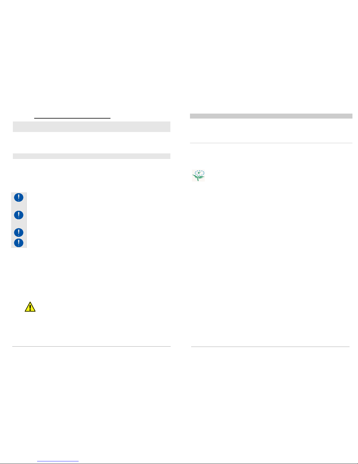
The opening stroke-end of the actuator can be adjusted by selecting the dipswitches located inside the actuator underneath the black rubber plug (T) (see fig.
below), near the label that indicates the state of the dip-switches.
The setting can be made very easily by selecting the dip-switches as specified in the
table below.
STROKE
(mm)
DIP-SWITCH
WITHOUT
BK-LOCK
WITH
BK-LOCK
1 2 3 4 4
70 ON
OFF OFF
OFF ON
125
OFF
ON
OFF
170
OFF OFF
ON
210
OFF OFF OFF
The actuator is factory-set with the longest stroke (210 mm).
10.2. Closure stroke-end
The stroke-end at closure is automatic and cannot be programmed.
The actuator stops when the charge is absorbed when the window is completely
closed and the weather stripping is completely depressed.
After each closure or intervention of electronic protection devices, the chain will
move about 1 mm in the opposite direction to give correct compression to the seals
and release the mechanical parts.
12
10.3. Operation with BK-LOCK electromechanical lock
The actuator can also work in combination with the BK-LOCK electromechanical
lock; this operating mode can be selected using dip-switch No.4. If the dip-switch is
set on ON without the lock being connected, the actuator will not move.
11. Actuator kit with electromechanical lock
Warning. Always comply with the correct electrical connections between
the two machines; an incorrect connection may damage the machines and
create a hazardous situation.
11.1. Electrical connection and operating logic
In order for the two machines to work in combination with one another, the required
connection must be made by connecting the wires according to the following
diagram.
In the BK-LOCK electromechanical lock select, using dip-switch No. 1, the desired
stroke and set, using dip-switch No. 2, the “
OPERATION WITH ACTUATOR
” mode (see
instructions in the BK-LOCK manual also).
Power the two machines with a voltage of 24V (wire No. 1 and No. 2), inverting
the polarity to open and close the system. Powering wire No. 2 with +24V and
wire No. 1 with -24V produces the following effects:
the lock moves in the opening direction;
the lock arrives at stroke-end, stop;
the chain actuator begins opening, opening the movable sash;
the KIMO chain actuator reaches stroke-end.
Powering wire No. 1 with +24V and wire No. 2 with -24V produces the following
effects:
the chain actuator moves in the closing direction;
the actuator reaches stroke-end and stops with a short relax;
the lock moves in the closing direction;
the lock arrives at stroke-end.
Important note. If, during the closing movement, the chain actuator stops
suddenly due to an overload or mechanical sticking, this state is
interpreted as a "closing stroke-end" and thus the lock motor performs a
closure, even if the sash is not effectively closed.
BK-LOCK
ACT
UATOR
Page 7
13
11.2. Sound diagnostics in case of anomaly
1 Beep
The lock is set in "with actuator" mode but does not receive any
commands from the actuator.
- The lock does not move because it didn't receive the command.
- Check the contact of wire "3" of the lock and that dip-switch No. 2 of the
actuator is on ON.
4 Beeps The actuator (or actuators) are in error.
- The lock is ready for the command but the connected actuators are in error.
- Check the diagnostics of the actuators connected to the electromechanical
lock.
12. Checking for correct assembly
Check that the window is perfectly closed at corners and that there are no
obstacles caused by incorrect positioning during assembly.
Check that when the window frame is closed the chain terminal is at least a
few millimetres away from the actuator body. This will ensure the window is
properly closed and seals are correctly compressed. In the event that this
should not be the case there is no guarantee that the window is closed
correctly.
Check that hinges and support brackets are aligned to each other and tightly
fixed against the window frame with screws fixed correctly into position.
Check that the window reaches the desired position according to the strokeend selected.
13. Emergency manoeuvres, maintenance or cleaning
In the event that the window frame should require manual opening due to power
failure or problem with the mechanism or for normal maintenance or external cleaning
of the window frame, in built-in actuators it’s necessary to perform these operations:
1. Unscrew the two screws that fix the sash to the attachment bracket.
2. Take care during this operation since the bracket, which is in two pieces after
removing the screws, may fall as it is no longer secured.
3. Manually open the window frame.
ATTENTION: DANGER – the window could fall as the sash is no longer
held in position by the chain.
4. After maintenance and/or cleaning repeat points 1 and 2 in reverse order.
14. Troubleshooting
Possible causes of malfunction during installation or use.
14
Problem Possible cause Solution
Actuator does not work
No electricity at feeder
Check status of circuit
breaker or safety switch
Cable not connected or
wire disconnected.
Check electrical
connections at reduction
motor
15. Environmental protection
All materials used in the manufacture of this appliance are recyclable.
We recommend that the device itself, and any accessories, packaging,
etc. be sent to a centre for ecological recycling as established from laws
in force on recycling. The device is mainly made from the following
materials: aluminium, zinc, iron, plastic of various type, cuprum. Dispose
materials in conformity with local regulations about removal.
16. Certificate of guarantee
The manufacturer will guarantee good function of the appliance. The
manufacturer shall undertake to replace defective parts due to poor
quality materials or manufacturing defects in accordance with article 1490
of the Civil Code.
The guarantee covers products and individual parts for 2 years from the
date of purchase. The latter is valid as long as the purchaser possesses
proof of purchase and completion of all agreed conditions of payment.
Guarantee of good function of appliances agreed by the manufacturer
implies that the latter undertakes to repair or replace free of charge and in
the shortest period possible any parts that break while under warranty.
The purchaser is not entitled to any reimbursement for eventual direct or
indirect damage or other expenses incurred. Attempt to repair by
personnel unauthorised by the manufacture shall render the warranty null
and invalid.
The warranty does not cover fragile parts or parts subject to natural wear
and tear or corrosion, overload, however temporary etc. The
manufacturer will accept no responsibility for eventual damage incurred
by erroneous assembly, manoeuvre or insertion, excessive stress or
inexpert use.
Repairs performed under guarantee are always "ex factory of the
manufacturer". Respective transport expenses (out/back) are the
responsibility of the purchaser.
Page 8
15
17. Dichiarazione di Incorporazione (per una quasi macchina) e
Dichiarazione CE di Conformità / Declaration of incorporation (for
a partly completed machine) and EC Declaration of Conformity.
Con la presente il / Hereby the
Costruttore:
Manufacturer:
Nekos Srl
Via Capitoni 7/5- 36064 Mason Vicentino (Vicenza) - Italy
Tel +39 0424 411011 – Email [email protected]
dichiara sotto la propria responsabilità che i seguenti prodott i:
declare under its own responsibility that the following produc ts:
Descrizione prodotto :
Product Designation:
Attuatore a catena per finestre
Window chain drive
Modello:
Type :
23
0 V : KATO 253
- KATO -
KATO 305
KATO SYNCRO3 - KATO 305 SYNCRO3
INKA 356 - INKA 356 SYNCRO3
24 V : KATO 253 - KATO - KIMO - KATO 305
KATO SYNCRO3 - KATO 305 SYNCRO3
INKA 356 - INKA 356 SYNCRO3
Anno di costruzione dal / Year of manufacturing from: 2017
Soddisfano gli applicabili requisiti essenziali della
Direttiva Macchine 2006/42/EC, Allegato I
Fulfil the essential requirements of the Machinery Directive 2006/4 2/EC, Annex I, Art. 1.1.2, 1.1.3, 1.1.5,
1.2.1,1.2.3, 1.2.6; 1.3.2, 1.3.4, 1.3.9, 1.5.1, 1.5.2, 1.5.6, 1.5.7, 1.5.8, 1.5.9, 1.5.10, 1.5.11, 1.7.1, 1.7.1.1, 1.7.3,
1.7.4.2, 1.7.4.3
La documentazione tecnica pertinente è compilata secondo l’Allegato VII, sezione B
The relevant technical documentation is compiled in accordanc e with Annex VII, Part B
La persona autorizzata a costituire la documentazione tecnica pertinente è:
The person authorised to compile the relevant technical docume ntation is: ing. Matteo Stefani – Nekos S.r.l.
Su richiesta adeguatamente motivata delle autorità naziona li, la documentazione tecnica dei citati prodotti sarà resa
disponibile, via e-mail, entro un tempo compatibile con la sua importanza.
In response to a reasoned requ est by the national authorities, we will p rovide, via e-mail, the relevant information on
the product listed above within an adequate period proportion al to its importance.
Inoltre i succitati prodotti sono conformi alle disposizioni pertinenti delle seguenti Direttive:
Furthermore the products listed above complies with the provi sions of followings Directives :
2014/30/EU Direttiva Compatibilità Elettromagnetica / ElectroMagn etic Compatibility Directive (EMCD)
2014/35/EU Direttiva Bassa Tensione / Low Voltage Directive (LVD )
2011/65/EU Direttiva sulla restrizione dell’uso di determinate sostanze pericolose nelle apparecchiature
elettriche ed e lettroniche (Direttiva RoHS) / R estriction of the use of certain hazardous substances Directive
(RoHS Directive)
e delle seguenti norme armonizzate e/o specifiche tecniche:
and of the following harmonised standards and/or technical s pecifications:
EN 60335-2-103 ; EN 61000-6-3:2007 + A1:2011 ; EN 61000-6-2:2005 + AC:2005
EN 60335-1:2012 + EN 60335-1/A11:2014 ; EN 50581:2012
La messa in moto di una macchina completa che includa la quasi macchina sopra menzionata, da noi fornita, non è
permessa finché non sia accertato che l’installazione sia stata fatta secondo le specifiche e le indicazioni di
installazione contenute nel “Manuale d ’istruzioni” fornito con la quasi-macchina e che sia stata espletata e
documentata, in apposito protocollo, una procedura di accettazione da parte di un tecnico abilitato.
Commissioning of the complete machinery including the above m entioned drives delivered by us is no t allowed until it
is ascertained that the installation of the complete ma chinery was performed in acc ordance with the specifications and
the operating and installation advice given in our Mounting Instructions, and that the acceptance procedure was duly
carried out and documented in an acceptance protocol by a sp ecialist.
Questa dichiarazione è fatta dal costruttore / This is dec lared by the manufacturer:
NEKOS SRL - Via Capitoni 7/5 - 36064 Mason Vicen tino (Vicenza) - Italy
Rappresentato da / Represented by :
Giuliano Galliazzo – A.D. Presidente / President CEO
Luogo e data / Place and date : Mason Vicentino 28/07/2017 Firma / Valid signature
16
NEKOS S.r.l. - Via Capitoni, 7/5
36064 Mason Vicentino (VI) – ITALY
+39 0424 411011 – +39 0424 411013
 Loading...