


Streak Retinoscope RX-RC
Instruction Manual
Thank you for purchasing the NEITZ Streak Retinoscope RX-RC. This is a battery-powered
retinoscope. For charging battery an optional Dual Desk Charger RC-II is exclusively used.
Please read this instruction manual carefully before use to avoid unexpected accidents, and store
it in a safe place for future reference. Please also read the instruction manual of the Dual Desk
Charger RC-II carefully when the charge for battery is required. For more detailed information for
operating please refer to a technical book for retinos copy.
TD11-10890031E-2

Table of Contents
1. Important Information ................................................................................................................ 1
1-1 Intended Use ...................................................................................................................... 1
1-2 Symbols ............................................................................................................................. 1
1-3 Labeling on Package ......................................................................................................... 2
1-4 Safety Information .............................................................................................................. 3
2. Checking Package Contents and Nomenc latur e ...................................................................... 5
3. Operation ................................................................................................................................... 7
3-1 Charging RX-RC ................................................................................................................ 7
3-2 Turning Illumination ON/O F F ............................................................................................. 8
3-3 V ar ying and Rotat ing Strea k .............................................................................................. 8
3-4 Screening ........................................................................................................................... 8
3-5 Astigmatic Axis Examination ............................................................................................ 10
3-6 Determining Refraction .................................................................................................... 10
3-7 Accessories ...................................................................................................................... 10
4. Troubleshooting ........................................................................................................................ 11
5. Maintenance ............................................................................................................................ 12
5-1 Cleaning ........................................................................................................................... 12
5-2 Replacing Battery............................................................................................................. 12
5-3 Replacing Bulb ................................................................................................................. 13
5-4 Disposal ........................................................................................................................... 13
6. Specifications .......................................................................................................................... 14
7. Contact Information ................................................................................................................. 20

situation which, if not avoi ded, may r esult in minor o r moderate injury.
may also be used to alert against unsafe practices that may cause
accompanied by the serial
Manufacturer. This symbol should be accompanied by the name and
hows that this device may not be disposed of together
with general household waste and can be recycled separately from
1. Important Information
For the U.S. Market;
CAUTION: Federal law restricts this device to sale by or on the order of a physician.
1-1 Int e nde d Us e
The NEITZ Streak Retinoscope RX-RC (hereinafter , called as “RX-RC”) is a bat tery-powered
retinoscope intended to measure the refract ion of the eye by illuminating the re tina and noting
the direction of movement of the light on the retinal surface and of the refraction by the eye
of the emergent rays.
1-2 Symbols
The following symbols are used on this manual and/or package to assist you in proper
handling and using this device, and to w ar n and caut ion you of potential hazards to yourself
and others.
Indicates a potentially haz ardous situation which, if not avoided, could
result in death or serious injury.
Used with the safety alert symbol, indicates a potentially hazardous
It
property damage.
Prohibited action (must not be performed).
Required actions (that must be performed) based on the instructions.
Serial number. This symbol should be
number of the device.
address of the manufactur er.
This sym bol s
other household waste un der the WEEE directive.
Symbol of Nickel-Hydrogen Secondary Battery to be recycled.
1

to consult the instructions of the device for
his symbol shows the lower and upper humidity limits for storage
his symbol shows the lower and upper atmospheric pressure limits
ionizing radiation or RF
Ni-Cd
Environmental conditions for
transport and storage
This symbol instructs
information on how to pro per ly us e it.
This symbol shows the lower and upper temperature limits (°C) for
storage and transport.
T
and transport.
T
for storage and transport.
Fragile. Handle with care.
Keep dry.
Nickel-cadmium rechargeable battery.
Potentially hazardous levels of nontransmitters (not applica ble to the RX-RC)
Barcode for traceability pur poses.
1-3 Labeling on Package
The following label has been adhered to the Outer Package of the RX-RC to assist you in
the proper transport and st or age of the device
2

Do not use together with parts other than standard accessories
Do not turn the illumination on when covered with the plastic bag and
the like. It may cause the inside high temperature and result in injury,
Do not touch the bulb with bare hands immediately after turned off
impact to the device during the bulb is lighted or immediately
Do not use in extremely humid place or co me in contact with salt water ,
Do not use thinner, cleaning agents, or boiled water to clean the
into the gaps of device. It may
1-4 Safety Information
For your safety please strictly comply with the following precautions. Failure to comply may
cause safety problem or device failure.
Do not illuminate the light more than required to observe the fundus of
patient’s eye. It may damage the patient’s eye.
including in this package. Problems or damage may occur.
Do not apply a strongly impact. I t may cause injury or device failur e.
device failure or fire.
since it is still hot. It may result in injury.
Do not
after turning the bulb of f. It may cause breakage of bulb fi la me nt.
Do not operate in direct sunlight or harmful light. Doing so may create
high heat or damage of the device.
or allow water to come in contact with t he device. It may caus e dev ice
failure.
Do not sterilize the device. I t may cause de form atio n or device failure.
device. It may cause deformation or device failure.
Do not insert any foreign materials
cause device failure.
3
case during movement or
transportation. Doing so may protect against deformation or device
Remove the battery when the device will not be used for long periods
Do not attempt to disassemble or modify the device. Doing so may
Do not touch the device with wet hands. Doing so may cause device
Be sure to use original Carrying
failure.
Be sure to use genuine battery without fail. Not doing so may cause
device failure.
of time to prevent from ele ct r olyte leakage.
result in electrical shock, f i r e or device failure.
failure.
4

③ ② ④
⑥ ⑦
⑩
⑫
⑯
2. Checking Package Contents and Nomenclature
Make sure to match all items in the package wit h the component s shown belo w. Inspect
each item for damage. If any items are missing or damaged, do not use the device and
immediately contact y our local d ealer.
(The RX-RC consists of a r et inoscope head RX, a handle an d a r echargeable battery.)
Before using the RX-RC for the first time, clean it according to the instructions given in
this manual.
(1) Retinoscope Head RX (Hereinafter, called as “Head”) …….. 1 unit
⑪
⑤
⑧
(2) Battery Handle (hereinafter, called as “Handle”) …….. 1 unit
①
⑨
(1) Headrest Mount
(2) Viewing Window
(3) Viewing Window Rim
(4) Illumination Opening
(5) Reference Line
(6) Streak Varying Lever
(7) Head Rotation Ring
(8) Streak Rotation Ring
(9) Head Joint
(10) Logo of Manufacturer
(11) Logo of Model Name of
Head
(12) Serial Number of Head
⑬
(13) Switch Button
(14) Switch Ring
(15) Bottom Cap
⑭
(16) Serial Number of Handle
(3) Headrest…… 1 piece
⑮
5
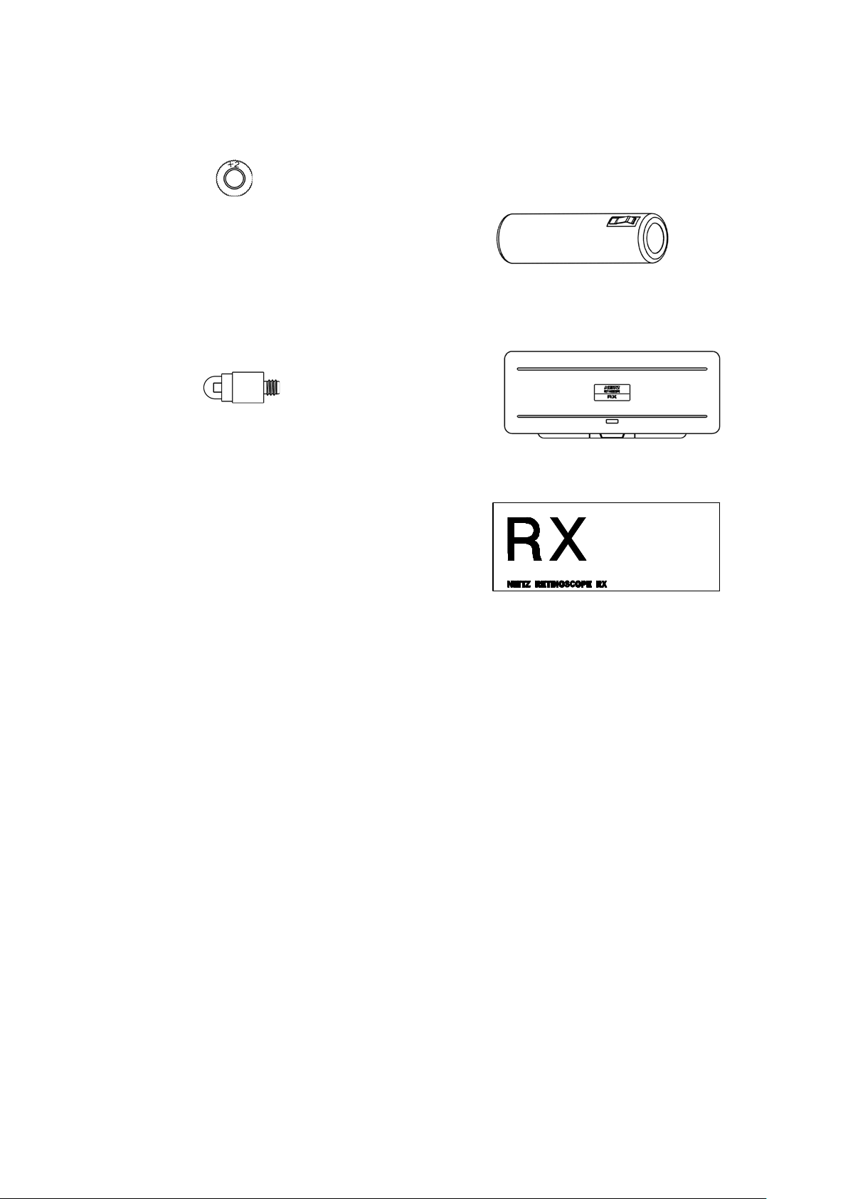
(4) Presbyopic Lens ……. 1 piece (5) Rechargeable Battery …… 1 piece
Type: 1000RS
Output Voltage 3.6V
(6) Spare Bulb …….. 1piece (7) Carrying Case ……. 1 piece
Type: L-27
(8) Instruction Manua l ……. 1 set (9) Outer Package …… 1 piece
6

unable.
3. Operation
3-1 Charging RX-RC
Charge the RX-RC with the optional Dual De sk Charger RC-II (hereinafter, called as
“RC-II”) sold separately.
RX-RC
It is available to charge 2 set s of t he RX-RC
simultaneously
ME System
Charging Ports
RC-II (Non-medical device)
Insert the Handle of RX-RC into the charging port of RC-II, w hich is exact ly co nnecte d
to the AC power t hrough the AC adaptor, until it stops as shown in the above figure. Be
sure to turn the RX-RC off during charging.
Full charging of battery is completed after approx. 15 hours from an uncharged
condition.
When fully charged the RX-RC can b e illu minate d for approx imate ly 80 minutes at t he
maximum amount of light.
Read the instruction man ual for RC-II
Be sure to charge the RX-RC after turning it off. If still ON, it
may create high heat felt hot in touch as well as charging is
7

Illumination OFF Illumination ON
Fig. 3-2a
Fig. 3-2b
Fig. 3-2c
Fig. 3-3
Reference
Streak
Streak
Streak
3-2 Turning Illumination ON/OFF
While pressing the Switch button on the Handle,
rotate the Switch ring to the left (towards ON) to
turn the power and light on. (Fig. 3-1)
Since the light adjustment function is built in the
RX-RC, the further t he Switch rin g is rotat ed to the
left (towards ON), the brighter the light becomes.
To turn the light off, rotate the Switc h but ton to the
right until it completely ret urns to the OFF posit ion.
Fig. 3-1
3-3 Varying and Rotating Streak
By shifting the Streak varying lev er upward and down ward based on the re ference line,
it is available to vary the streak as f ollo ws. The reference point on the Streak varying
lever is the top of it.
(1) Upper position than the reference line: Convergent ray (Fig. 3-2a)
(2) On the reference line: Parallel ray (Fig.3-2b)
(3) Lower position than the reference line: Divergent ray (Fig. 3-2c)
Line
Varying Lever
Rotation
Ring
In addition, the streak can be rotated 360 degrees with no limit by turning the Streak
rotation ring (see Fig. 3-3).
3-4 Screening
(1) Turn the RX-RC on and shift the Streak varying lever fully downward to obs erve
the divergent ray.
When the divergent ray is used, f ol low t he pr ocedure below.
8

Projected
Reflex
Shadow
Scanning
Direction
[Against
(2) While the gazing point of the examined eye is set to far point that is no regulated
power, illuminate the light t o the examined eye from the distanc e of 50cm. (3) Approach to t he Viewing window of RX-RC as much as poss ible to look in. (4) Observe the movement of reflex against the projection direction by scanning the
projected light on fundus of eye slowly and horizontally. On this occasion, scan it
in the direction of perpendicular to the lengthwise dir ec t ion of l in ear streak.
(5) The relation between the motion of reflex and the refraction in condition of naked
eye (in case the trial lens is not used in front of examined eye) is as follows (Fig.
3-4). (a) Movement (The reflex moves in the same direction as t he projected light ): Myopic eye, emmetropic eye, or hyperopic eye of -2D or under (b) Neutrality (The moveme nt of ref lex st ops.): Myopic eye of -2D (c) Against Movement (The reflex moves in the opposite direction to the projected
light.) Myopic eye of -2D or over * The abov ementio ned princip le is applied only to the situation used t he divergent
ray, and the motion of reflex is the reverse direction when the convergent ray is
used.
[Movement]
light
[Neutrality]
Movement]
Fig. 3-4
* The v alue o f “-2 D” d epend s on the di stanc e o f exa minatio n, and it is deter mine d
by calculating -1 divided by examination distance [m] .
9

Fig. 3-5
3-5 Astigmatic Axis Examination
When the angles of scann ing the examined eye and the moti on of reflex are not related
with the movement or against movement but are the same, this meridian of eye is a
main meridian. If they are not the same, the angle of movement of reflex is a main
meridian, and the meridian w hich is apart 90 degrees from the ma in meridian becomes
the other meridian. Either o f their merid ians is astigmatic axis.
3-6 Dete rmining Refraction
(1) Scan the naked eye and wear in 12mm front of patient’s eye the (+) lens in case
of movement or the (-) lens in case of aga inst move ment (or by using retinoscopy
rank), and find the neutrality point by increasing 0.5 to 1.0D.
* Since against movement is hard to observe comparing with movement, if
against movement exists, more high accuracy neutrality can be obtained by
adding the (-) lenses until movement can be observed and increasing the (-)
lenses step by step.
(2) The relation bet w een t he lens power required for neutralization and the refraction
is shown below.
Refraction = Lens power requ ired f or neutralization –
(1/examination distance[m])
(3) After confirming t he refrac tion of the main meridian, find the neutral ity point of the
other main meridian in the sam e pr ocedures.
3-7 Accessories
(1) Headrest
When performing the examination with
glasses on, remove the cover on t he Headrest
mount to insert the accessory Headrest into
there (see Fig. 3-5). It is hard to scratch the
glasses by operating the RX-RC while putting
the Headrest on your for ehead.
(2) Presbyopic Lens
W hen using the presbyopic lens, loosen and
turn the Viewing window rim to be removed,
and then put the presbyopic le ns on it.
* +2D of presbyopic lens is provided as the stanada r d accessory.
10

if burned
The filament of bulb is
Install the bulb exactly without any
It is not abnormal for heat to be generated when the light is on.
may increase to the level t hat it may
4. Troubleshooting
If the RX-RC does not function properly, some problems may be solved by referring to
the following chart. If the problem ca nnot be reso lv ed, st op using and contact your local
dealer or Neitz immediate ly.
The following table shows the possible causes and troubleshooting solutions.
Problem Possible Cause Solution
Battery is not installed. Install the battery.
Light does not turn
on.
Battery is discharged. Charge the battery.
Bulb has burned out.
Replace with a new bulb
out.
The shape of
streak is curved.
The RX-RC
becomes hot when
the light is on.
curved by external impact.
Bulb comes loose.
The temperature on RX-RC
feel warm or hot to the touch.
Replace it with a new bulb.
looseness.
11

Do not sterilize the device. It may cause deformation or device
Be sure to use genuine battery without fail. Not doing so may
Fig. 5-1
5. Maintenance
5-1 Cleaning
If the device becomes dirty , wipe the surface with dry lint-free cloth or lint -free soft cloth
slightly moistened wit h di l uted neutral detergent, an d t hen dr y all surfaces completely.
Disinfection by using alcohol may be carried out at the minimum to clean the surface
of the device. Use a blower and the like to remove dust or dirt out of the Viewing window .
Do not use thinner, cleaning agents, or boiled water to clean the
device. It may cause deformation or device failure.
failure.
5-2 Replacing Battery
cause device failure.
As the battery is deteriorated by repeated charges, the bat tery power and the operatin g
time decrease little by little. It is strongly recommended to replace with a new battery
for use of approximat ely 2 years as a guide. The batt ery is replac ed in accor dance wit h
the following procedure.
(1) Rotate the Bottom cap counterclockwise to
detach it and remove the cur r ent bat tery.
(2) Insert a new battery in the direction in which
the metal terminal portion is on the Bottom
cap side as shown in Fig. 5-1.
(3) Screw the Bottom cap clockwise on the
Handle.
Metal terminal portion
12

Do not touch the bulb with bare hands immediately after turned
Fig. 5-3
5-3 Replacing Bulb
off since it is still hot. I t may result in injury.
When the illumination is not turned on, the bulb may have burned out. In accordance
with the following procedu re, confir m the co ndition o f the
bulb and replace it with a new one if burned out.
(1) As shown in Fig. 5-2, hold t he Head and the Handle
with both hands. Hold ing the H ead, t wist the Handle
counterclockwise to detach it from the Head.
(2) The bulb appears in the to p of the det ached Ha ndle.
Check the filament of bulb. If the filament is broken,
replace it with a new one.
* 1 piece of bulb is provided as an accessory.
(3) Turn t he bulb counterclockwise t o r emove it.
(4) Replace a new bulb to the original position in the
reverse procedure of removal (Fig. 5-3). Attach the
Head to the Handle.
Do not directly touch the glass part of the bulb with
your hands and be sure it remai ns clean.
Head
Fig. 5-2
5-4 Disposal
Safely dispose of the RX-RC and accessories, except rechargeable batteries, in
accordance with local regulations and/or environmental guidelines.
The rechargeable batt ery that conta in pre cious r esou rces can be r eused.
Do not discard but recycle used rechargeable battery in accordance with
your local rules, regulatio ns and/or guidelines.
13

Continuous Light
Hours
Dimensions and
battery)
Continuous operation
6. Specifications
Bulb Rating 4V, 2.6W
Battery used Ni-Cd rechargeable battery, 1000RS
Streak Divergent ray, Parallel ray, Conver gent ray
Streak Rotation 360 degrees with no limit
Approximately 80 minutes
Headrest
Presbyopia Lens
Weight (including
Safety Standards
To protect the glasses from contacting to the RX-RC
+2D
34(W) x 32(D) x 269 (H)mm, Approx. 380g
(1) Safety: IEC 60601-1:2005 Ed.3.1:2012
ISO 15004-1:2006
(2) EMC: IEC 60601-1-2 Ed. 3.0:2007
(3) Form of protection against elect r i cal shocks:
Internal power supply equi pment
(4) Class of the level of electri c al sh ock protection:
Ty pe B equipment
(5) Level of protection against entry of water and particles:
IPX0
(6) Method of sterilization:
Do not sterilize
(7) Suitability for use in an oxygen rich environment:
Do not use in oxygen rich environments
(8) Mode of operation
Options
(1) Dual Desk Charger RC-II
(2) Rechargeable Batter y 1000RS
(3) Bulb L-27
(4) Presbyopic Lens (+1D)
(5) Presbyopic Lens (+2D)
(6) Presbyopic Lens (+3D)
(7) Headrest
14

Environmental Conditi ons
Use
Storage
Transport
+10 °C to +35 °C
-10 °C to +55 °C
-10 °C to +55 °C
(50 °F to 90 °F)
(14 °F to 131 °F)
(14 °F to 131 °F)
30 % to 90 %
10 % to 95 %
10 % to 95 %
(no condensation)
(no condensation)
(no condensation)
Atmospheric
Pressure
Temperature
Relative Humidity
800 hPa to 1060 hPa 500 hPa to 1060 hPa 500 hPa to 1060 hPa
15

The RX-RC is intended fo r use in t he electromagnetic environ m ent specified below. The
customer or the user of the RX-RC should assure that it is used in such an environment.
RF emissions
The RX-RC uses RF energy only for its internal
nearby electronic equipm ent.
RF emissions
The RX-RC is suitable for use in all
supplies buildings used for domestic purposes.
Harmonic emissions
Volta ge fluctuations/
The RX-RC is suitable for use in all
supplies buildings used for domestic purposes.
ANNEX
EMC Guidance
The RX-RC is a medical d evice and requires special precautions regarding EC. Refer t o
the following EMC information for appropriate insta ll at ion a nd putting into service.
Take care when using portable and mobile RF communications equipment i n pr ox i m ity of
the RX-RC, as they can affect performance.
(1) Designated Cable
Power cord for AC adapter
(2) Using accessories, transducers or cables other than those provided by Neitz may
result in increased emiss i ons or dec reased immunity of the RX-RC.
(3) Do not use the RX-RC adjacent to or stacked w it h ot her equipment.
In cases where adjacent or s t acked use is necessary, verify the RX-RC operates
normally prior to use.
(4) Guidance and Manufacturer’s Declaration – Electromagnetic Emissio ns
Guidance and Manufacturer’s Declaration – Electromagnetic Em issions
Emissions Test Compliance Electromagnetic Environment - Guidance
CISPR 11
CISPR 11
IEC 61000-3-2
flicker emissions
IEC 61000-3-3
Group 1
Class B
Not Applicable
Complies
function. There fore, its R F emissions are very low
and are not likely to cause any int erference in
establishments, including do mestic
establishments and thos e directly connected to
the public low-voltage power supply net work that
establishments, including do mestic
establishments and thos e directly connected to
the public low-voltage power supply net work that
16

The RX-RC is intended fo r use in t he electromagnetic environ m ent specified below. The
customer or the user of the RX-RC should assure that it is used in such an environment .
Electrostatic
± 6 kV contact
± 6 kV contact
Floors should be wood,
Electric fast
± 2 kV for power
± 2 kV for power
Mains power quality shoul d
Surge
± 1 kV line(s) to
± 1 kV line(s) to
Mains power quality shoul d
Volta ge dips, short
<5 % U
<5 % U
Mains power quality shoul d
Power frequency
3 A/m
3 A/m
Power frequency magnet ic
NOTE UT is the AC mains voltage prior to application of the test level.
(5) Guidance and Manufacturer’s Declaration – Electromagnetic Immunity
Guidance and Manufacturer’s Declaration – Electromagnetic Immunity
Immunity Test
discharge (ESD)
IEC 61000-4-2
transient/burst
IEC 61000-4-4
IEC 61000-4-5
interruptions and
voltage variations
on power supply
input lines
IEC 61000-4-11
IEC 60601 Test
Level
± 8 kV air
supply lines
line(s)
T
(>95 % dip in UT)
for 0.5 cycle
40 % UT
(60 % dip in U
)
T
for 5 cycles
70 % UT
(30 % dip in U
)
T
for 25 cycles
<5 % U
T
(>95 % dip in UT)
for 5 s
Compliance
Level
± 8 kV air
supply lines
line(s)
T
(>95 % dip in UT)
for 0.5 cycle
40 % UT
(60 % dip in U
)
T
for 5 cycles
70 % UT
(30 % dip in U
)
T
for 25 cycles
<5 % U
T
(>95 % dip in UT)
for 5 s
Electromagnetic
Environment – Guidance
concrete or ceramic tile. If
floors are covered with
synthetic material, the
relative humidity should be
at least 30 %.
be that of a typical
commercial or hospital
environment.
be that of a typical
commercial or hospital
environment.
be that of a typical
commercial or hospital
environment. If the user of
the RX-RC requires
continued operation during
power mains interruptions,
it is recommended that th e
RX-RC be powered from an
uninterruptible power
supply or a battery.
(50/60 Hz)
magnetic field
fields should be at levels
characteristic of a typical
location in a typical
IEC 61000-4-8
commercial or hospital
environment.
17

The RX-RC is intended fo r use in t he electromagnetic environ m ent specified below. The
customer or the user of the RX-RC should assure that it is used in such an environment.
Portable and mobile RF
= 1.2√
= 1.2√
= 2.3√
where is the maximum output
NOTE 1 At 80 MHz and 800 MHz, the higher frequency range applies.
absorption and reflection from structures, objects and people.
a
Field strengths from fixed transmitters, such as base stations for radio (cellular/cordless) telephones and
Over the frequency range 150 kHz to 80 MHz, field strengths should be less than 3 V/m.
Guidance and Manufacturer’s Declaration – Electromagnetic Immunity (continued)
Immunity Test
Conducted RF
IEC 61000-4-6
Radiated RF
IEC 61000-4-3
IEC 60601 Test
Level
3 Vrms
150 kHz to 80 MHz
3 V/m
80 MHz to 2.5 GHz
Compliance
Level
3 Vrms
3 V/m
Electromagnetic Environment –
Guidance
communications equip ment should be
used no closer to any part of the RXRC, including cables, than the
recommended separation distance
calculated from the equation
applicable to the frequency of the
transmitter.
Recommende d separation distance
150 kHz to 80 MHz
80 MHz to 800 MHz
800 MHz to 2.5 GHz
power rating of the transmitt er in w at t s
(W) according to the transm itt er
manufacturer and is the
recommended separation distance in
meters (m).
Field strengths from fixed RF
transmitters as deter mined by an
electromagnetic site survey,
be less than the complian ce level in
each frequency range.
Interference may occur in t he vicinity
of equipment marked with t he
following symbol:
NOTE 2 These guidelines may not apply in all situations. Electromagnetic propagation is affected by
land mobile radios, amateur radio, AM and FM radio broadcast and TV broadcast cannot be predicted
theoretically with accuracy. To assess the electromagnetic environment due to fixed RF transmitters, an
electromagnetic site survey should be con sid ered. If the measured field strength in the location in which
the RX-RC is used exceeds the applicable RF compliance level above, the RX-RC should be observed to
verify normal operation. If abnormal performance is observed, additional measures may be necessary,
such as re-orienting or relocating the RX-RC.
b
18
b
a
should

below, according to the maxim um output power of the commu ni c at i ons equipment.
Separation distance according to frequency of transmitter
m
= 1.2√
80 MHz to 800
= 1.2
√
800 MHz to 2.5
= 2.3
√
For transmitters rated at a max imum output power not listed above, the recommended
absorption and reflection from structures, objects and people.
(6) Recommended Separation Distances Between Portable and Mobile RF
Communications Equip m ent and the RX-RC
Recommended Separati on Distances Betwe en Port able and
Mobile RF Commu nications Equi pm ent and the RX-RC
The RX-RC is intended fo r use in an e lectromagnetic environment in which radiated RF
disturbances are control led. The customer or the user of the RX-RC can help prevent
electromagnetic interfer ence by maintaining a minimum d ist ance between portable and
mobile RF communications equipment (transmitter s) and the RX-RC as recommended
Rated maximum
output power of
transmitter
W
0.01 0.12 0.12 0.23
0.1 0.38 0.38 0.73
150 kHz to 80 MHz
MHz
GHz
1 1.2 1.2 2.3
10 3.8 3.8 7.3
100 12 12 23
separation distance in meters (m) can be estimate d usin g t he equation applicable to
the frequency of the trans m itter, where
in watts (W) according to t he t r ansmitter manufacturer.
NOTE 1 At 80 MHz and 800 MHz, the separation distance for the higher frequency range applies.
NOTE 2 These guidelines may not apply in all situations. Electromagnetic propagation is affected by
(7) Essential Performance of the RX-RC
No. Essential Performance Operation Mode
1 Uninter r upt ed charging Charging Mode
2 Cont inuous steady illumination Illumination Mode
is the maximum output rating of the transmitter
19

7. Contact Information
If you have any questions or need technica l suppor t, cont act y our local dealer or NEIT Z
located at the following addr ess .
[LOCAL DEALER]
Neitz Instruments Co. Ltd.
4F Ichibancho Court, 15-21, Ichibancho, Chiyoda-ku,
Tokyo 102-0082, Japan
Phone: (+81) 3-3237-0552; Fax: (+81) 3-3237-0554
e-mail: int@neitz.co.jp
URL: http://neitz-ophthalmic.com/
20

FOR YOUR NOTE:
21

Manufactured by
NEITZ INSTRUMENTS CO., LTD.
4F Ichibancho Court, 15-21, Ichibancho, Chiyoda-ku,
Tokyo 102-0082, Japan
Phone: (+81) 3-3237-0552; Fax: (+81) 3-3237-0554
e-mail: int@neitz.co.jp
URL: http://neitz-ophthalmic.com/
Distributed by
As part of our policy of continued product improvement we reserve the right
to alter and/or amend specifications at any time without prior notice.
TD11-10890031E-2
Printed in Japan
201901
 Loading...