

Page 1
Bio-shredders
LLiibbrreettttoo iissttrruuzziioonnii
OOppeerraattoorr’’ss MMaannuuaall
GGeebbrraauucchhssaannwweeiissuunngg
LLiivvrreett ddeess IInnssttrruuccttiioonnss
MMaannuuaall ddee IInnssttrruucccciioonn
“ R 500T “
Page 2

La ditta NEGRI in qualunque momento si riserva il diritto di apportare alla propria produzione modifiche e miglioramenti ritenuti necessari a suo
insindacabile giudizio. / NEGRI reserves the right to make any modifications and improvements to its products that it considers necessary at any time.
/ La Maison Negri se garde le droit de changer à n’importe quel moment les donnés, les poids et les mesures. / Negri tiene el derecho de cambiar
datos, pesos y medidas en cualquier momento. / Die Firma Negri kann in jedem Moment Daten, Gewichte und Maβ e ä ndern. / Negri bedhout zich het
recht voor om gegevens, gewichten en maten te wijzigen zonder aankondiging vooraf.
Le immagini presenti in questo libretto istruzioni hanno scopo puramente illustrativo. / The picture shown in this manual onlly have an illustrative
purpose. / Lef photos qui se trouvent danf ce livret d’instructions sont purement illustratifs. / Las im à genes presentes en este manual de instrucciones
tienen un fin exclusivamente illustrativo. / Die in diesen Gebrauchsanweisungen enthaltenen Bilder haben nur einen erlä uternden Zweck. / De
afbeeldingen in dit instructieboekje hebben alleen maar een illustratieve betekenis.
2
Page 3

TABLE OF CONTENTS PAGE
Introduction 4
Aim of the machine 4
Warnings and safety directions 4
Assembly 6
Transport 7
Information on use 7
Maintenance 13
Wiring diagram 18
Hydraulic system 19
Storage 20
Guarantee 20
Technical specifications 21
3
Page 4

INTRODUCTION
This manual is to be considered part of the machine. Distributors of new and used
machines are required to issue a document stating that the user ’s manual has been
delivered along with the machine itself. Operators are strongly required to read the
manual thoroughly and carefully before undertaking any kind of operation on the
machine.
AIM OF THE MACHINE
The R500bio-shredder is a machine designed for professional uses. It is particularly
suitable for the treatment of bulk material. It grinds up all sorts of vegetable waste
(pruning and garden waste, hedges, fruit and vegetable waste, wooden boxes, wooden
packages, pallets and so on). When working, it always considers the size, the quantity
and the quality of the material to be shredded.
WARNINGS AND SAFETY DIRECTIONS
Operator’s safety measures
People under the age of 16 are not allowed to use the shredders.
When attending the machine, the user is responsible for any damages, which might
occur to third parties.
During the shredding sessions it is absolutely necessary to wear protective gloves and
glasses. It has been proved that, following an uninterrupted use, the allowed noise
level is exceeded. It is therefore advisable for the user to wear ear-protection devices,
too.
During the shredding session the user always has to wear robust shoes and long
trousers.
Hair must be gathered up.
Do not use the machine if you are tired, ill or if you have taken medicines, drugs as
well as if you have been drinking alcoholics.
When the machine is working, please do not use ladders or stools to get to the driving
roller located at the bottom of the hopper, unless the machine is off.
Do not approach the working area of the cardan shaft transmission when it is
working.
Please use cardan shaft transmission gears provided with a free wheel device. The
transmission-gears must be in compliance with the regulations envisaged by the
machine guideline.
Safety measures concerning the machine
When starting the machine, please make sure that all its parts are assembled correctly .
Replace the broken or the damaged parts before using the machine.
The machine has to be placed on a flat and steady base.
4
Page 5

Before leaving the shredder unattended, it is necessary to stop the tractor and to
disconnect the transmission shaft.
It is compulsory to use the machine with all its safety devices correctly mounted to it.
Roll the discharging conveyor belt completely open and turn it on before starting
introducing the material.
Never modify the machine.
Do not use the machine for purposes, which are different than the ones it was
designed for
Safety measures during the shredding session
When using the bio-shredder, the operator must wear the individual safety devices; he
must stay close to the hopper into which he inserts the material he wishes to grind up.
He has also to make sure that nobody is around within radium of 20 meters.
Please do not insert branches having bigger sizes than the foreseen ones (18 cm as
stated in the picture graph on the hopper).
Please do not insert any stones, metals, glass, plastic, earth, and newspaper bundles
and so on in the bio-shredder but only vegetable materials.
Do not remove any protection housing when the machine is working.
The operator shall keep off the discharging conveyor belt when the machine is
working.
Do not get close with any parts of your body to the protection housings.
When the machine is working, do not let any parts of your body get close to the
transmission-gear. The PTO of the tractor has to revolute at an approximate speed of
540 revolutions/minute. Please do not let it revolute faster than that.
Safety measures when maintaining
For the maintenance of the machine, please follow the procedures mentioned in
MAINTENANCE.
Use original spare parts only.
When replacing the hammers and when carrying out the cleaning processes, please
watch out not to cut yourself. "Cutting-heads are very dangerous!"
Start carrying out the maintenance only after you have worn protective gloves and
stopped the tractor; wait until the rotor has come to a complete stop.
Safety during transport and storage
Please make sure that all parts of the shredder are well fastened to the trailer not to
lose anything during transport.
The machine must be transported with great care and the engine must be off.
Please use the appropriate hooks to lift the machine.
5
Page 6
Before transporting the machine hooked to the tractor, please disconnect the
transmission shaft.
ASSEMBLY
The R500 bio-shredder is delivered to you fully assembled and, therefore, ready to
use.
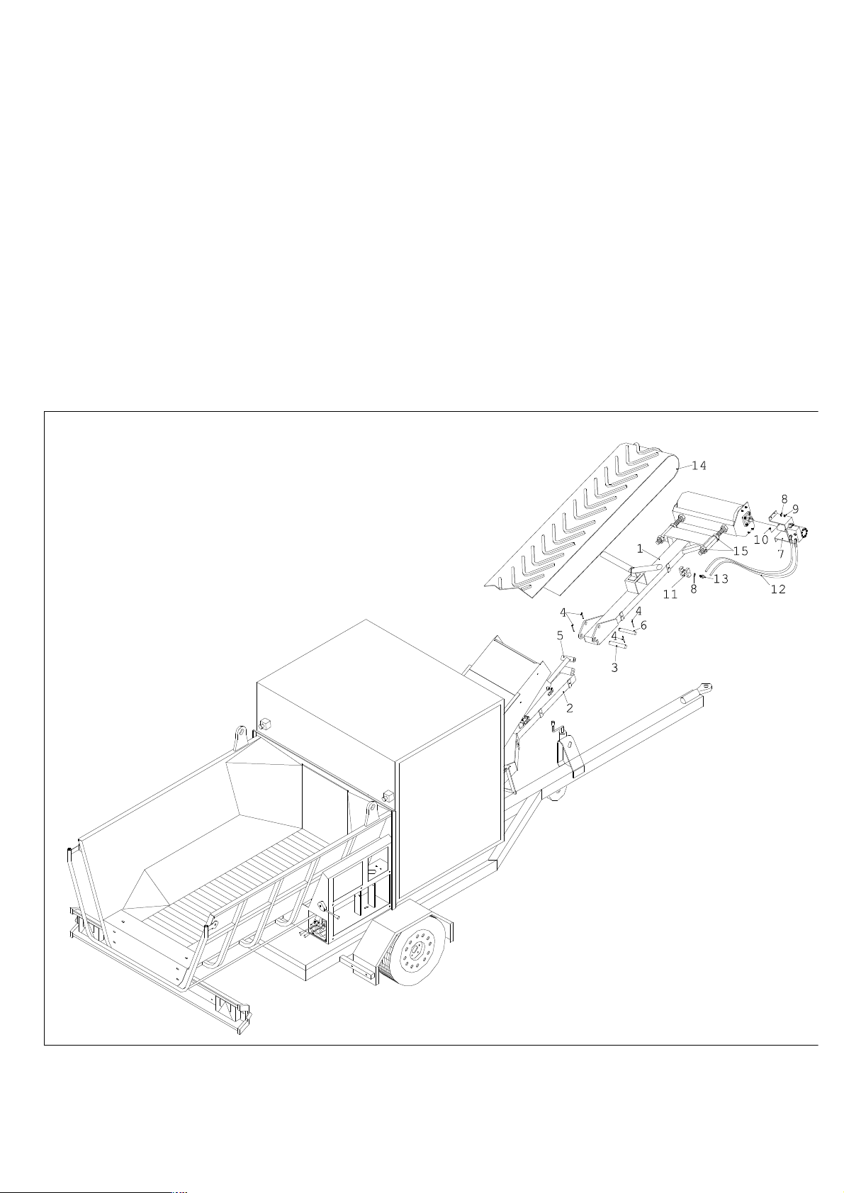
If you purchase an unassembled machine, please use the exploded diagram (picture
1), the basic components list and the corresponding instructions to carry out the
assembly of the machine in the correct way.
It is of the utmost importance that trained and authorized staff only sees to the
assembly of the machine.
Fig.1
6
Page 7

Basic list of components
1 Mobile conveyor belt frame 9 m8 aut nut
2 Fixed conveyor belt frame 10 M8x10 dowel
3Gudgeon pin for conveyor belt frame 11 m8 collar
4 A4x50 split pin 12 hydraulic pipes
5 Cylinder 13 screw for the collar
6 Mobile pin for cylinder 14 rubber conveyor belt
7 Hydraulic engine frame 15 M27 nut
8 8 Flat washer
Directions for assembly:
Please wear protective gloves first.
Fix the mobile conveyor belt frame (1) to the fixed one (2) by using the pin for the
conveyor belt frame (3). Block the pin with the two split pins (4).
Let the bush of the cylinder (5) overlap with the holes of the mobile conveyor belt
frame (1); insert the mobile pin for the cylinder (6) and block it with the two split
pins (4).
Assemble the hydraulic engine frame (7) on the mobile conveyor belt frame (1) by
using the four flat washers (8) and the four M8 nuts. Block the coupling made
through the dowel (10). Put the hydraulic pipes (12) in place in the collars (11) ; bolt
the screws (13) placing the washers (8) in between.
Place the rubber conveyor belt (14) on the roll of the mobile conveyor belt frame (1)
and, using the four M27 nuts (15), stretch it until it touches the scraper of the mobile
conveyor belt frame (2). The conveyor belt (14) must be centred as to roll freely.
TRANSPORT
Authorised trailers only can transport this Bio-Shredder. Before transporting the
machine hooked to the tractor, please disconnect the transmission shaft.
During transport, fasten the machine to the trailer as well as you can, making sure
that the Bio-Shredder does not exceed the allowed limits of the overall volume of the
means of transport used.
INFORMATION ON USE
Working times
According to the regulations for noise reduction, Bio-Shredders can not be used at the
following times: on working days from 1:00 p.m. to 3:00 p.m. and from 7:00 to 7:00
a.m. of the following day; on bank holidays from 1:00 p.m. to 3:00 and from 10:00
p.m. to 7:00 a.m. of the following day.
7
Page 8

Activation
Please place the bio-shredder on a flat and dry
surface. Let it hooked to the trailer. Make sure that
all protection housings are closed. Make also sure
that the levels of the hydraulic oil, of the oil in the
multiplier unit and of the oil in the reducers (see
paragraph “Maintenance”) are not under the allowed
limit. Unblock the machine from its trailer by using
the lever (picture 1). Turn the lever of 90° until it
reaches its working position. Once the lever is in its
working position, please block it. Pull out the two
supporting feet from underneath the hopper and
place them on the ground, placing thick wedges
between the feet and the soil (picture 2).
Connect the cardan joint to the tractor in the correct
way. Make sure that the “free wheel” device is in
Photo1
PTO of the bio-shredder and that the safety-locks
are in their appropriate seatings. Next, fasten the
safety chains to a fixed part of the bio-shredder and
of the tractor so that the external protection housing
does not rotate. Switch the tractor on and let it go at
its minimum. Connect the PTO of the cardan shaft.
Let the clutch go very slowly so that the shredder
can start working slowly. Start accelerating and
increase the pace more and more until you reach an
engine revolution number of the tractor allowing to
get 540 revolutions at PTO. No-stress display:
3000/3200 revolutions/minute
Adjustment of the no-stress device
The main aim of the No-stress device is to control
the action of the driving roll/apron conveyor
automatically, thus avoiding possible lodgements in
Foto2
the shredding unit.
The No-stress device is controlled or adjusted by the
operators through a 4 button panel.
You can carry out this operation only if the display is on.
When using the machine, the screen displays the instantaneous revolution number of
the rotor.
Through the button panel you can control the following functions:
1st Function: adjustment of the minimum revolution number
2nd Function: adjustment of the maximum revolution number
3rd Function: control of working hours
8
Page 9

ADJUSTMENT OF THE MINIMUM NUMBER OF REVOLUTIONS
Keeping the screen on, press the button “Clr” three times and the button “Min” one
time. A number between 0 and 3500 will be displayed. The very number equals the
current minimum number of revolutions when the device sets in to block the feeding
roll.
At this point, if you wish to increase or decrease this minimum number of
revolutions, you simply have to press the buttons “max” or “min” according to your
needs.
Once you have chosen the minimum number of revolutions, you have to save it by
pressing “Ent” twice and then “Clr” to go back to the instantaneous number of
revolutions.
ADJUSTMENT OF THE MAXIMUM NUMBER OF REVOLUTIONS
Keeping the screen on, press the button “Clr” three times and the button “Max” one
time. A number between 0 and 3600 will be displayed. This number equals the
current maximum number of revolutions when the device sets in to activate the
feeding roll.
At this point, if you wish to increase or decrease this maximum number of
revolutions, you simply have to press the buttons “max” or “min” according to your
needs.
Once you have chosen the maximum number of revolutions, you have to save it by
pressing “Ent” twice and then “Clr” to go back to the instantaneous number of
revolutions.
The maximum number of revolutions for the machine to set in must equal or be lower
than the instantaneous number displayed on the screen when the machine is empty.
WORKING HOURS CONTROL
Keeping the screen on, press the button “Clr” three
times and the button “Ent” once. The screen will
display the hour amount worked by the machine. In
order for the screen to display the instantaneous
number of revolutions again, press the button “Clr”
once.
There is no ideal maximum or minimum number of
revolutions at which the no-stress device should set
in since the speed of the feeding roll is as variable
as the material you can shred.
Anyway, we suggest you to choose a value between
3000 revolutions/minute and 3200
revolutions/minute as the maximum number of
revolution. As far as the minimum number of
revolution is concerned, we recommend a value
Foto3
between 2900 and 3100 revolutions/minute.
9
Page 10

10
It is not possible to calibrate the minimum number of revolutions so that it is equal or
higher than the maximum number. The same goes the other way round.
Use
Unfold the conveyor belt open by using the
outer lever of the distributor (picture 3, lever
upwards to open it; lever downwards to close
it).
Turn the conveyor belt on by using the central
lever (picture 4. Lever in the middle means that
the conveyor is still; lever downward means
that the conveyor belt is moving). Start the
apron conveyor by using the control shackle
(picture 5) located on the front part of the
hopper. This shackle allows you to control the
direction of the apron conveyor (operatorintroduction-inversion-stop-hopper).
It is possible to control the speed of the
conveyor belt and of the apron conveyor
Foto4
through the appropriate regulators located under
the corresponding levers (picture 6).
Once the operator has put his gloves, glasses and headphones on, he can start
introducing leaves, twigs and branches, provided that the input material has a
maximum diameter of 18 cm.
It is understood that when we say 18 cm, we mean the largest diameter, which can be
shredded, considering a soft or medium hard wood variety. It goes without saying
that if you use harder wood varieties, the maximum diameter you can shred decreases
proportionally.
The material to be minced can also be introduced in the hopper using a bucket or a
mechanical fork.
To get the best performances from the machine, we suggest you to insert the material
at a pace, which can allow the tractor to work over its maximum torque.
If you need to grind up wet material or fibrous materials such as linden trees, pines or
palms, please decrease the inserting speed to avoid any lodgements of the machine.
Accidental cases and what to do accordingly
(Please use the exploded diagram and the basic list of components at the end of the
this booklet)
Page 11

11
THE BIOSHREDDER DOES NOT IDLE
Please make sure that the cardan joint is connected
directly to the tractor and to the shredder: the
safety locks must be in their appropriate seatings.
If the failure goes on, please call a technician.
STALLING OF THE CUTTING HEADS
BECAUSE OF TOO MUCH MATERIAL
INSERTED OR FOLLOWING THE
ACCIDENTAL INSERTION OF STONES OR
BIG METAL PIECES
(Use the exploded diagram and the list of
components at the end of the manual)
Switch off the engine and wear safety gloves. Open
the door on the left (73) and take out the two spring
washers first (132) and then the two pins for the
Foto5
sieve (131). Remove the lid of the back protection
housing (125) by unscrewing the 6 nuts (2). At this point you can extract the sieve
(130)
Clean the cutting unit and remove all the residues
of vegetable waste that are still inside
Please handle the hammers in the machine very
carefully (they can cause serious injuries)
Assemble everything again and idle the BioShredder. Every time, after a stalling of the cutting
unit for the above mentioned reasons, check if the
driving belts and the cutting group still work
correctly and make sure that the blades, the
hammers and the shafts, which are inserted in, are
still integral (see paragraph “Maintenance”)
STALLING OF THE MACHINE BECAUSE
OF STUCKED MATERIAL BETWEEN THE
DRIVING ROLL AND THE ROTOR
Foto6
Open the door on the right (72) and the one on the
left (73). Unhook the springs (48) by unbolting the
nuts (50). Lift the driving roll (54) and, by using the levers, remove the material
lodged between the rotor (144) and the driving roll (54). Assemble everything again.
STALLING OF THE BIOSHREDDER DUE TO LACKING FUEL IN THE
TRACTOR
Fill the fuel tank of the tractor. Please do not start the machine since the driving belts
Page 12

12
could break because of overheating.
Before re-starting the bio-shredder, please remove any branches stuck under the
driving roller (54). In order for you to do so, please unhook the springs (48) and then
lift the driving roller (54) Clean the cutting unit as described in the previous
paragraph.
STALLING OF THE INPUT HYDRAULIC SYSTEMS
If the roller (54) and the apron conveyor (145) are stalled, make sure that you did not
push one of the emergency buttons by mistake (274) or that the rotor is not working
at a too low pace, that is to say inferior to the maximum revolution number set on the
no-stress device.
In the first case you simply have to unblock the switches by twisting them slightly. In
the second circumstance you have to work on the accelerator lever of the tractor.
Make sure that the fluid regulator is open (picture 6). If the problem is still there even
after the above-mentioned checking procedures, turn the tractor off and check that no
objects are in the way thus preventing the roller (54) or the apron conveyor from
working correctly. (145). If there are some, please remove them. Make sure that the
machine has no leaks within the hydraulic system and that the level in the oil tank
(149) is visible from the level indicator. Make sure that the flexible coupling (112) is
in good condition and that it can transfer the motion to the pump (109). If the
breakdown persists, please contact an authorized technician.
STALLING OF THE DISCHARGING HYDRAULIC SYSTEMS
If the discharging conveyor belt is not rolling (194), make sure that the fluid regulator
is open (picture 6) and that no objects are in the way thus preventing it from working.
If there are some, remove them. Next, check that the outer hedges of the conveyor
belt do not rub against some fixed parts of the machine. If so, please centre the
conveyor properly by using the four M27 nuts (198).
BAD FUNCTIONING OF THE NO-STRESS DEVICE
If the no stress screen does not lighten up when the machine is working, make sure
that the sidelights of the tractor are on. Check the cable connecting part to the tractor
and all the connections inside the no-stress box.
If the display is on but it reports a wrong number of the revolutions of the rotor, make
sure that the sensor (236) is located at approximately 2 cm. from the circumference
described in the references (113). Check the adjustment of the no-stress device as
previously described. If it has been wrongly adjusted, please carry on the correct
adjustment.
Make sure that the electro-valves (255-146) are not blocked or burnt.
Should any damages occur to the electronic card (231) of the no-stress device or of
Page 13

13
the sensor (236), you could disable the no-stress device through its switch (289). This
way you can work manually by using the control shackle (picture 5). Please contact
an authorized technician anyway.
EXCESSIVE VIBRATIONS
The possible reasons for such a failure could be: unbalance of the cutting unit caused
by the inclination of one or more shafts that support the hammers; breaking down of
one or more hammers ; loosen driving elements. Find out the source of the problem
and contact a technician for its repairing.
MAINTENANCE
(Use the exploded diagram and the list of components at the end of the manual)
Before each checking, maintenance or cleaning operation to be carried out at the end
of every working session, please switch the tractor off.
We strongly advise you to wear working gloves.
Cleaning of the shredding unit:
Clean the machine as described in the
previous paragraph “ Accidental cases and
what to do accordingly ” and remove all
possible residues left inside the bioshredder. When doing so, please act very
carefully since the cutting heads are very
dangerous. Assemble everything back.
Cleaning, checking and replacing the
apron conveyor:
After every working day, we advice you
Foto7
remove the protection housing on one side
of the hopper (191) by unbolting the four nuts (118) so that you can clean the apron
conveyor (145) and the driven roller (185) through the inspection overlay of the
hopper (picture 7). Please make sure that the apron conveyor is not too stretched
(there should be a 3/ 4 cm subsidence when pressing the upper part of the apron
conveyor itself at around 15 cm from its beginning). If so, loosen it by using the
threaded bars (187).
A too stretched apron conveyor leads to the breaking down of its joints. It can also
cause a decrease in the performance level of the machine. Through the same
inspection overlay, it is possible to evaluate the wear of the tubes of the apron
conveyor. If the wear exceeds 3.5 mm, please replace the tubes. Loosen the apron
conveyor by using the threaded bars (187) and replace a louver (171-172) or the
entire apron conveyor (145). In order for you to do so, take down the hydraulic
engine (92) by unbolting the two screws (24) and by pulling out the spring washers
(173) from the upper part. You have to pull out four of them if you are replacing a
Page 14

14
louver only (171-172) and two of them if you are replacing the entire apron conveyor
(145). Roll the rolling shutter until the louver without spring washers reaches the
inspection overlay; extract the pin for the apron conveyor (170) and replace the
louver or the complete apron conveyor. Mount the missing pin again (170) by using
the inspection overlay, move back the louver without spring washers to the upper
part, insert the washers on both sides and stretch the apron conveyor according to the
directions previously explained.
Checking and replacing the leads for the apron conveyors
By using the same inspection overlay as described in the previous paragraph, you can
make sure that the height of the six polythene leads for the apron conveyor (260) is
not less than 15mm. If they are shorter, please replace them.
Disassemble the apron conveyor as previously described, unbolt the screws blocking
the leads (261 or 262), replace the worn ones (260) and bolt the screws again.
The lateral leads (263 and 264) are to be found on the sides of the apron conveyor
and you have to replace them when their thickness decreases from 5 to 2 mm. To
replace them, what you have to do is unbolting the screws (118) located on the outer
side of the loading hopper, remove the worn leads and replace them with new ones.
Fix them using the screws (118).
Checking the discharging conveyor belt
We suggest you to check the tension of the conveyor belt (194) once a month. If
needed, please stretch it by using the four M27 nuts (198). The conveyor belt is
stretched correctly if, when rolling, it touches slightly against the scraper of the fixed
conveyor belt structure (217) without actually brushing any fixed part of the machine.
A too high tension can lead to the breaking of the chain belt itself or to a decrease in
the performance level of the machine.
Checking, rotation and replacement of the hammers:
Please check the wear of the hammer tips every 50 working hours (Picture 2). In
order for you to carry out this checking procedure, open the doors (72 and 73), take
down the two lids (175) by unscrewing the nuts (2), remove the two spring washers
first (132) and then the two sieve pins (131). At this point, please remove the back
protection housing (125) by unscrewing the six nuts (2) and take the sieve out (130).
Please make sure that the tips of the hammers are
in good condition (picture 2); if not, have them
rotated or replace them.
Disassemble the leads of the conveyor (127) by
unbolting the six nuts (2); disassemble the rubber
OKNO
strips (128) by unscrewing the four screws (63);
eventually disassemble the back protection housing
(126) by removing the 8 screws (41). To rotate or
to replace the hammers, please block the pin (136)
through a 30 spanner; unbolt the screw through a 6
Fig.2
Page 15

15
Allen screw (143) (if necessary, you can heat the 143 screw with a hairdryer)
When taking the pin (136) out, you can recover all hammers and all spacers. Before
you rotate or replace the hammers, please check the surface condition of the pins
(136, picture 3) and, if necessary, replace them.
Do the same for the other three rows, too. Eventually you can assemble everything
back together following the assembly chart of the rotor carefully (picture 4)
A wrong assembly of the hammers and of the spacers
will cause harmful vibrations.
When replacing damaged parts, please use original spare
NO!
parts only. They have to be marked with the name of the
manufacturer. The operator will easily find these original
spare parts at the constructing company NEGRI
OK
Fig.3
MARCO.
In case the blades have been subjected to heavy impacts or blows, a technician must
test them.
Page 16

16
Assembly chart of the rotor
DISTINTA BASE:
n°144 Rotore
n°136 Perno rotore
n°137 Martello
n°138 Distanziale spessore 14mm
n°141 Distanziale spessore 5mm
n°140 Distanziale spessore 10mm
n°139 Distanziale spessore 15mm
n°142 Rondella svasata
n°143 Vite svasata piana 10x25
Ogni rotore ha 4 file ognuna
diversa dalle altre.
Ogni fila attraversa 4 settori
uguali.
144
quarto
settore
terzo
settore
secondo
settore
primo
settore
142
138
139
143
138
139
137
137
137
140
138
141
141
138
140
2
1
3
Fila 1
136
Fila 2
Fila 3
Fila 4
4
Fig. 4
Page 17

17
Stretching the driving belts:
Open the door on the right (72) and stretch the driving belts by using the regulators
(50) so that, if you press the belt with a finger, its lowering does not exceed its
thickness. When you have to replace the driving belts, please loosen the regulators
(50) so that the belts can come out from their seating. Replace the worn belts and
stretch them as previously described. Assemble everything back together.
The driving belts on the R 500 tractor model are SPB 1800.
Checking the height of the driving roller
We suggest you to make sure, by looking inside the loading hopper, that between the
driving roller (54) and the apron conveyor (145) there is al least 5mm backlash.
Should you adjust their height, please use the rules (51) located on the sides of the
machine when opening the doors.
Checking the flexible coupling
To verify the wear of the coupling (112), please open the left door (73) and make sure
that there is no backlash between the two parts of the coupling. If so, you have to
replace the coupling. To replace it, please loosen the two dowels (29); disassemble
the pump supporting structure (111) by unbolting the four nuts (2). Without taking
the pump out, take the coupling out. Replace it with a new one and assemble
everything again following the inverse procedure.
Cleaning of the air / oil exchanger
To get the maximum results out of the hydraulic system, we suggest you to clean the
splits with compressed air or water, always taking care of directing the jet parallel to
the splits in order not to damage them. It is of the utmost importance that the electric
engine is unplugged from the voltage during this operation and it is well protected
against the jet.
Levels
Hydraulic oil: It is possible to check the level of the hydraulic oil through the level
indicator located on the oil tank. If you need to top up, please use the SAE46 oil type.
Oil for reducers and multiplier: Check the oil level in the reducers through the
appropriate level caps (SAE 80w-90 kind).
Daily maintenance
Clean the machine outside.
Make sure that the screws and the nuts are tightened properly.
Make sure that all protection devices are sound and steady on the machine.
Clean the apron conveyor inside.
Clean the air/oil exchanger
Check the intactness of the driving belts.
Page 18

18
Extraordinary Maintenance
Check the condition of the hammers every 50 hours (137)
Every time you replace the hammers, check the condition of the rotor pins (136)
Check the wear of the tubes of the apron conveyor (145) every 100 hours.
Check the wear of the leads of the apron conveyor (260) every 100 hours
Check the height of the driving roller (54) every six months
Grease the 12 bearings (133-36-195-186-97) every 100 hours.
Check the wear and the backlash of the flexible coupling (112) every 100 hours .
Change the hydraulic oil ( SAE 46 kind) every 600 hours or 2 years.
Replace the hydraulic oil filter element when the red cylinder reaches the glass domeshaped element located on the oil filter (please use 25 μ m strengthened cellulose
filters)
After the first 150, please change the oil in the reducers; later on you can change it
every 2000 hours or at least once a year (SAE 80w-90 kind).
After the first 50 hours, please change the oil in the multiplier box; later on you can
change it every 500 hours or, at least, once a year (SAE 80w-90)
Page 19

19
STORAGE
Every time your working session with the machine is over, please turn the tractor off,
clean the shredding unit and check the stretching of the driving belts (see paragraph
Maintenance)
Make sure that the radiant mass of the air/oil exchanger is always clean to guarantee
performances in time and, above all, to guarantee that the electric parts work, as they
should. Clean the splits with compressed air or water taking care of directing the jet
parallel to the splits in order not to damage them. It is of the utmost importance that
the electric engine is unplugged from the voltage during this operation and it is well
protected against water jets.
Store the shredder indoors. If you store it in a cold place and if you are not using it
for a long time, we suggest you to loosen the driving belts and the discharging
conveyor belt. Please roll the conveyor belt completely open before storing the bioshredder (working position).
WARRANTY
The company NEGRI MARCO guarantees this machine against manufacturing
failures and against other failures related to the materials for 2 years starting from the
purchase date. The guarantee is valid for every person who acts for purposes, which
are not part of his commercial or professional activity.
The terms stated in this guarantee are in compliance with the 1999/44/CE European
Directive.
For people using the product for professional aims, the guarantee is valid only if it is
provided with the till receipt or the guarantee certificate (attached to this booklet),
filled in by the seller and sent within 10 days from the purchase date.
As far as the internal combustion engines and the electrical ones are concerned, the
guarantee which runs for them, is the one given by the engine builders, that it is valid
1 year long.
The guarantee excludes every responsibility related to direct or indirect damages to
people or things and its effect ends if the pieces returned were stripped down,
tampered or repaired by unauthorised centres. The guarantee does not cover the
damages caused by the non-respect of the use directions, either.
The parts that are largely used and for this reason get quickly worn, such as gaskets,
chains, belts, valves, bearings, hydraulic pipes, blades, etc., are not covered by the
guarantee.
The guarantee excludes also the transport costs, the costs for inspections, the
assembling and dismantling carried out by one of our technicians following the
customer’s request to solve problems which then resulted not to be dependent from
us.
In case of any damage, please contact an authorised centre and use original spare
parts, specifying the model and the version. When no original spare parts are
assembled, no guarantee right valid.
Page 20

20
TECHNICAL SPECIFICATIONS
Noise emissions
The acoustic pressure to the operator’s ear is in compliance with EN ISO 11201 and
modified by the regulations relating to the machine: 117-dB (A).
Total length: 5415 mm
Total width: 2030 mm
Total height: 2800 mm
Inserting height: 960 mm
Discharging height: 2700 mm
Hopper width: 1450/960mm
Hopper length: 2000mm
Weight: 2270 Kg.
Required tractor power: at least HP90
Number of revolutions at the PTO: 540 revolutions/minute
OVERALL DRAWINGS
posizione di trasporto
2000
960
5415
posizione di lavoro
1450
2700
2030
2800
Page 21

21
rator sticks to the directions given as to
WARNINGS AND SAFETY DIRECTIONS
front material discharge, he could get to the blades, if he leaned forward.
goggles
Before using the bio-shredder and before each checking, maintenance
or cleaning operation, please read the operator’s manual carefully.
It’s very important that the ope
avoid wrong manoeuvres that could lead to injure himself and third
parties.
We strongly suggest you to use protectionto prevent dust or any other dangerous material
from getting into your eyes .
Since during an uninterrupted use of the
machine the allowed noise level is exceeded,
please don’t forget to wear an ear-protection
device. The non-observance of this direction
could damage your ability to hear irreparably.
This sticker is to inform that this machine
consists of cutting tools. For this reason, it is
necessary for the operators to wear protection
gloves during work and maintenance.
This sticker informs that the protections of the cutting heads and the
hammers have been designed to prevent the operator, who stands in
front of the machine, from touching them. However, especially from the
Should it be necessary for the operator to lean forward, please make
sure to take all the necessary precautions, like switching the machine off
or wearing your protection gloves.
Page 22

22
position
working roller in the area. When performing
This sticker informs the operator that under the
working. It is therefore absolutely forbidden to
protection devices there are some driving-belts
put your hands in the spaces the manufacturer
left open for the machine to cool off. It is also
forbidden to use the machine without the
protection devices.
SUDDEN EJECTION OF SHREDDED
MATERIALS
This signal explains to the operator and to other
people being around the machine, that the machine
might eject some shredded material. For this reason
the operator must work in the suggested useonly. All other people are kindly required to keep a
distance of at least 20 meters from the machine
AD0037
MIND YOUR HANDS: working rollers
This sticker is to inform that there is a
every kind of operation beyond the ordinary
use of the machine, we suggest you to use all
the possible precautions such as stopping the
engine and wearing protection-gloves.
Page 23

23
La ditta NEGRI in qualunque momento si riserva il diritto di apportare alla propria produzione modifiche e miglioramenti ritenuti necessari a suo insindacabile
giudizio. / NEGRI reserves the right to make any modifications and improvements to its products that it considers necessary at any time. / La Maison Negri se
garde le droit de changer à n’importe quel moment les donnés, les poids et les mesures. / Negri tiene el derecho de cambiar datos, pesos y medidas en
cualquier momento. / Die Firma Negri kann in jedem Moment Daten, Gewichte und Maβ e ä ndern. / Negri bedhout zich het recht voor om gegevens, gewichten
en maten te wijzigen zonder aankondiging vooraf.
Le immagini presenti in questo libretto istruzioni hanno scopo puramente illustrativo. / The picture shown in this manual onlly have an illustrative purpose. /
Lef photos qui se trouvent danf ce livret d’instructions sont purement illustratifs. / Las im à genes presentes en este manual de instrucciones tienen un fin
exclusivamente illustrativo. / Die in diesen Gebrauchsanweisungen enthaltenen Bilder haben nur einen erlä uternden Zweck. / De afbeeldingen in dit
instructieboekje hebben alleen maar een illustratieve betekenis.
NEGRI
Via Motella 33 – Campitello(MN) Italia
Tel.0376/926162-Fax 0376/925329
Email:negribiotrituratori@libero.it
www.negribio.it
 Loading...