

Neff K7791X0 user Manual
K7791X0..
9000 291 220 (8707)
en Installation Instructions

Content
Important Information ........................................... 3
Installation Possibilities ........................................ 3
Stand alone appliance ............................................ 3
Stand alone appliance with dividing wall ................. 3
As an end section to a row of kitchen units ............. 3
Installing the appliance ........................................ 4
Installation location ................................................. 4
Atmosphere grades ................................................ 4
Installation niche ..................................................... 4
Neighbouring kitchen furniture ................................ 4
Subsurface ............................................................. 4
Electrical connection ............................................ 5
Water Connection ................................................. 5
Dimensions of the Installation Niche ................... 6
Setting-up as an stand alone appliance .................. 6
Site of the water connection ................................... 7
Appliance dimensions .......................................... 8
Tools and Accessories which are needed ........... 9
Scope of delivery .................................................... 9
Additional accessories ............................................ 9
Tools ...................................................................... 9
Miscellaneous ......................................................... 9
Installation manual ............................................... 10
1. Checking the installation niche ........................ 10
2. Transporting the appliance ............................. 10
3. Removing the packaging ................................ 10
4. Preparing the appliance .................................. 11
10. Adjusting the appliance in the niche ................ 15
11. Fixing the appliance to the niche ceiling .......... 16
12. Fastening the appliance to the side wall
of the installation niche ................................... 16
13. Connecting water to the appliance ................. 17
14. Attaching the base strip .................................. 17
15. The appliance is switched on .......................... 18
16. Preparing the furniture doors .......................... 18
17. Loading the appliance door ............................ 19
18. Attach the adjusting rib to the furniture door
(refrigerator compartment) .............................. 19
19. Hang and align the furniture door
(refrigeration compartment) ............................. 20
20. Attach the adjusting rib to the furniture door
(freezer compartment) ..................................... 21
21. Hang and align the furniture door
(freezer compartment) ..................................... 22
22. Fix the furniture door
(refrigerator compartment) .............................. 23
23. Fix the furniture door
(freezer compartment) ..................................... 24
24. Screw on the lower fixing angle ...................... 24
25. Fasten the finger protector .............................. 25
26. Attaching the covers ....................................... 26
27. Mounting the air separator .............................. 27
28. Setting the door opening angle
(refrigerator compartment door) ...................... 27
29. Tense the hinge screws
(refrigerator door) ............................................ 27
5. Preparing the installation niche ....................... 11
6. Attaching an additional anti-tilt mechanism ..... 12
7. Preparing the water connection ...................... 13
8. Attaching the edge protectors ........................ 13
9. Sliding the appliance into the installation niche 14
2
Important Information
Installation Possibilities
m Caution!
Setting up and mounting this appliance requires
extensive expertise in various trades (mechanics,
carpentry, plumbing, electrics).
It is the duty of the person setting the appliance up to
guarantee that it is set up and commissioned securely.
Mistakes in setting the appliance up and damage
resulting from this do not come under the warranty
of the manufacturer. Terms of guarantee are found
in the operating instructions of the appliances.
m Warning!
The appliances are very heavy and must be secured from
tipping when transporting, when mounting and when
operating. It is absolutely necessary to fit an anti-tip device.
Keep the doors closed until the appliance has been
mounted completely and secured according to the
instructions in these mounting instructions.
Because of the weight / dimensions of the appliance and
to minimise the risk of injuries and damage to the appliance
at least two persons are necessary to set-up the appliance
securely.
Use the appliances according to the prescribed
application.
Pull out the plug or remove the fuse before commencing
work on the appliance.
Only allow a specialist electrician to exchange a mains lead.
Only allow customer service to carry out repairs to the
appliance.
Apart from statutory national regulations, you should stick
to the connection terms relating to the local electricity and
water companies.
These mounting instructions are designed to help you
install your new appliance.
The manufacturer cannot be held liable for mounting which
has been improperly carried out. We recommend that you
allow a qualified specialist to set up and switch the
appliance on for the first time.
Following all information and keeping to the instructions are
preconditions for mounting and switching the appliance on
safely for the first time.
Keep the mounting instructions safe for use later on.
Before setting up and switching the appliance on for
the first time, read the mounting instructions fully and
thoroughly.
Various installation possibilities are available.
These are only limited by the kitchen design and the finger
protection function.
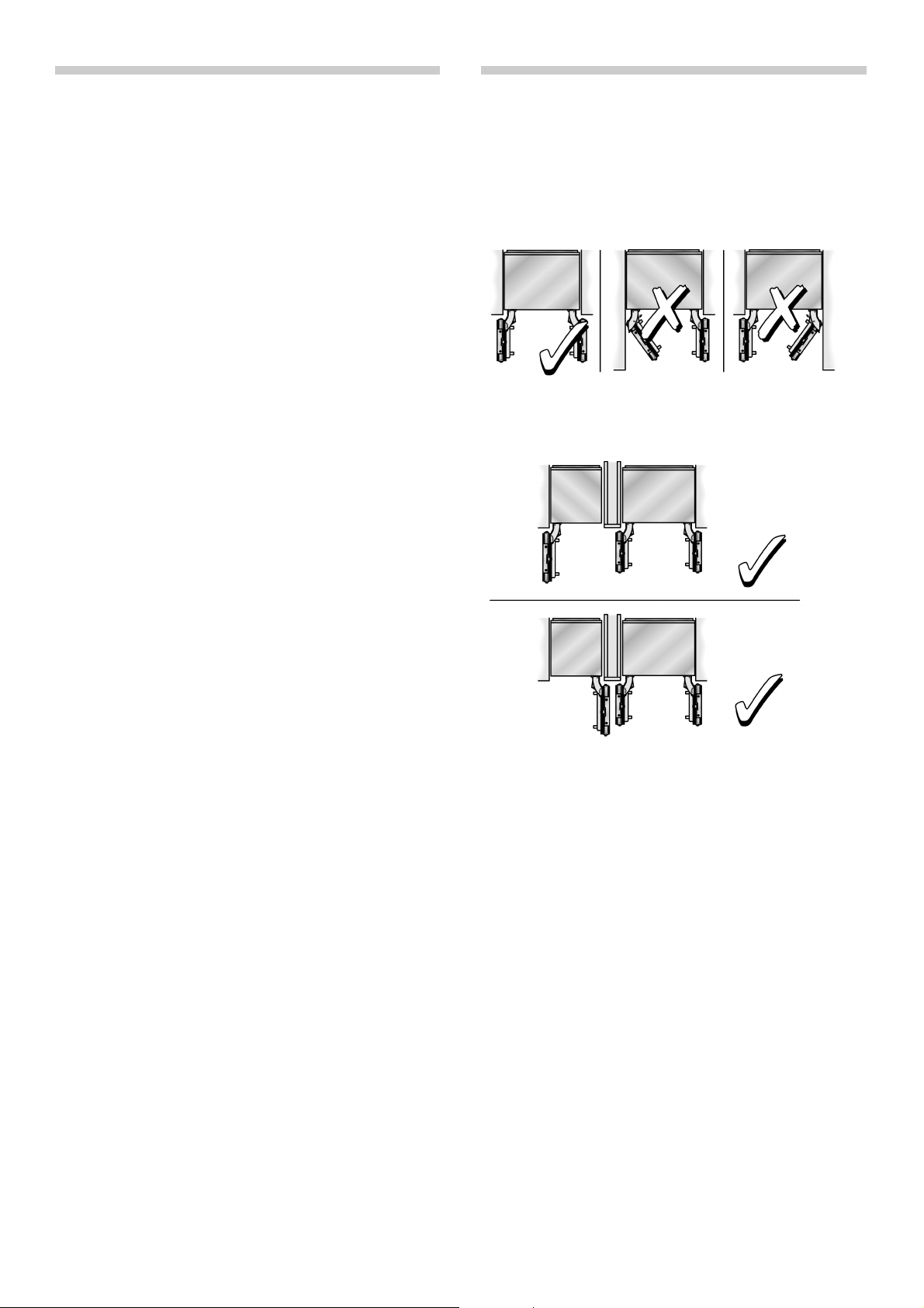
Stand alone appliance
Stand alone appliance with dividing wall
Note:
– When measuring the dividing wall for model 2,
pay attention to the thickness of the furniture front to
be mounted in order to avoid damage when opening
doors at the same time.
– If the distance between the appliances is less
than 160 mm, the heating kit for the side-by-side
combination should be used.
For further information see section “Additional
acessories” on page 9.
– The minimum thickness of the dividing walls is 16 mm.
As an end section to a row of kitchen
units
If a side of the appliance is visible, use a side covering.
The side covering must be connected firmly to the wall,
the floor and the upper cupboards before the appliance is
slid into the installation niche.
The dimensions of the side covering are governed by the
opposing niche wall. During installation, make sure that the
installation niche has right angles and has the exact size
necessary for the appliance.
3

Installing the appliance
Installation location
The appliance should be installed in a dry, well ventilated
space.
The location should not be exposed to the direct sunlight
and should not lie next to a source of heat such as
a cooker or a radiator etc. If installation next to a source of
heat cannot be avoided, either a suitable insulating plate
should be used or you should keep to the following
minimum distances:
– 30 mm from the electric cooker,
– 300 mm from a oil-fired or solid-fuel cooker.
m Caution!
The appliance is very heavy.
Empty weight: 195 kg
Atmosphere grades
The atmosphere grade is written on the identification plate.
It states the room temperature within which the appliance
can be operated.
Subsurface
m Caution!
A fully laden appliance is heavy.
Weight: up to 540 kg
The subsurface must be level and even in order to ensure
that the appliance is securely installed and works correctly.
The subsurface must be made from a hard, non-flexible
material.
The floor of the installation space must have the same
height as the rest of the space.
On account of the weight of a fully-laden appliance, it is
necessary to have a bearing subsurface. In the case of
doubt, the help of architect or specialist builder should
be enlisted.
Atmosphere
grade
SN +10 °C to 32 °C
N +16 °C to 32 °C
ST +16 °C to 38 °C
T +16 °C to 43 °C
Permitted ambient
temperature
Installation niche
It is important to keep to the stated dimensions of the
installation niche with a view to trouble-free fitting, and the
subsequent appearance of the kitchen furniture frontage.
Special care should be taken that the niche has right
angles. The side walls should not exhibit areas that stick
out, projections or unevenness.
You should determine the right angles of the installation
niche with appropriate means, e.g. by measuring
diagonally and by using a spirit level.
The side walls and the upper end of the installation niche
must be at least 16 mm thick.
Neighbouring kitchen furniture
The new appliance is screwed down tightly using parts
of the cabinet and the upper cabinet.
Care should therefore be taken, that all upper cabinets
to which something has been fastened are securely
connected to the subsurface or wall by appropriate
means.
The minimum thickness of the base should be a minimum
of 19 mm.
4

Electrical connection
Water Connection
Do not use an extension lead or a multi-plug socket.
Connecting this appliance, only use a plug which has
been installed securely.
The plug to secure the appliance must be freely accessible.
Connect the appliance to a 220–240 V/50 Hz ac current
via a plug which has been properly installed. The socket
must be fused with a 10 to 16 A fuse.
For appliances operated in non-European countries,
the identification plate should be checked whether the
electric supply and the current model stated match the
vales of the mains supply. For details regarding the position
of the identification plate, see section “Calling Customer
Service / Identification Plate”. Any necessary exchanging of
the mains lead should carried out by a specialist electrician.
m Warning!
On no account should the appliance be connected to
electric saving plugs or to converters which convert dc
current to 230 V ac e.g. solar appliances, marine
current mains networks.
A cold water connection is necessary for operating the
automatic ice maker. The water pressure must lie between
1.7 and 10 bar. The installation must correspond to the
local plumbing regulations.
A separate shut-off valve should be installed in the coldwater inflow.
The shut-off valve should not be located behind the
appliance. It is recommended that you mount the shut-off
valve directly next to the appliance or at another place
which is easily accessible.
When installing the water connection, pay attention to the
permissible installation area for the water mains. For more
information concerning the permissible installation areas,
see the section “Installation Dimensions”.
Note:
The maximum outside diameter of the water mains (without
connecting pieces) is 10 mm.
5
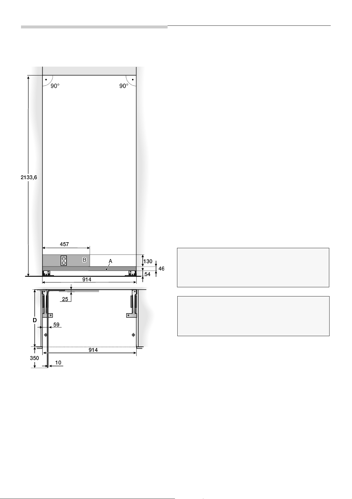
Dimensions of the Installation Niche
Setting-up as an stand alone appliance
Key:
A Area for installation of the water connection
The shut-off valve for the appliance’s water
connection is to be located in the immediate vicinity
of the installation niche such that it is accessible
without disassembling the appliance. If this is
absolutely unavoidable, the shut-off valve should be
only be installed in the area of the installation areas
labelled with A and B behind the appliance.
B Area for installation of the electric current
Important!
The upper niche wall must consist of a rigid, load bearing
material (minimum thickness 16 mm). The upper niche wall
must be completely even up to a depth of at least 100 mm
and free from bumps.
Important!
The lateral niche walls must be completely even and free
from bumps. If the niche is formed as a separate part, the
side walls must be completely even up to a depth of at least
100 mm and free from bumps.
D Depth of the installation niche, depending on the
kitchen design
D = 610 mm minimum!
Note:
The installation niche must have right angles. The side
walls should not exhibit areas that stick out, projections
or unevenness.
6
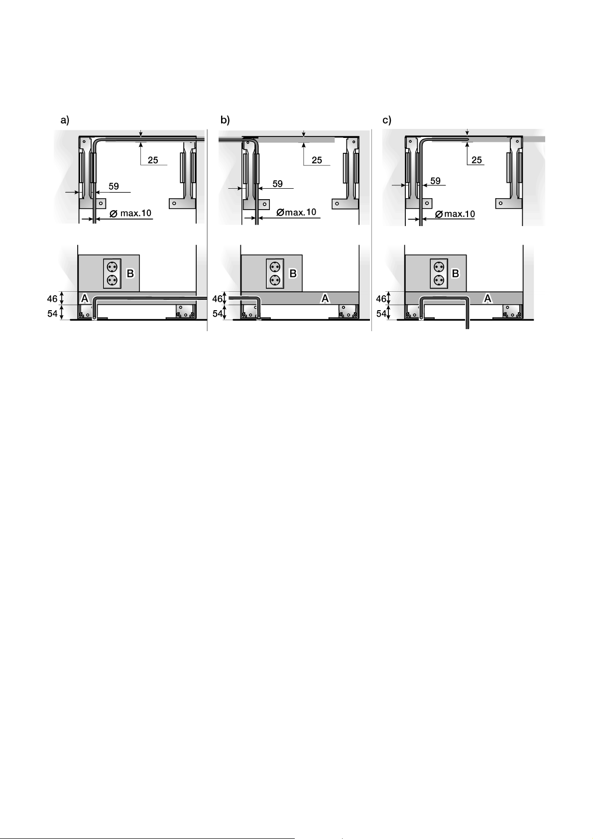
Site of the water connection
The mains supply can be laid to the appliance from the
right-hand side (a), from the left-hand side (b) or from the
space below the appliance (c).
Key:
A Area for installation of the water connection
B Area for installation of the electric current
7
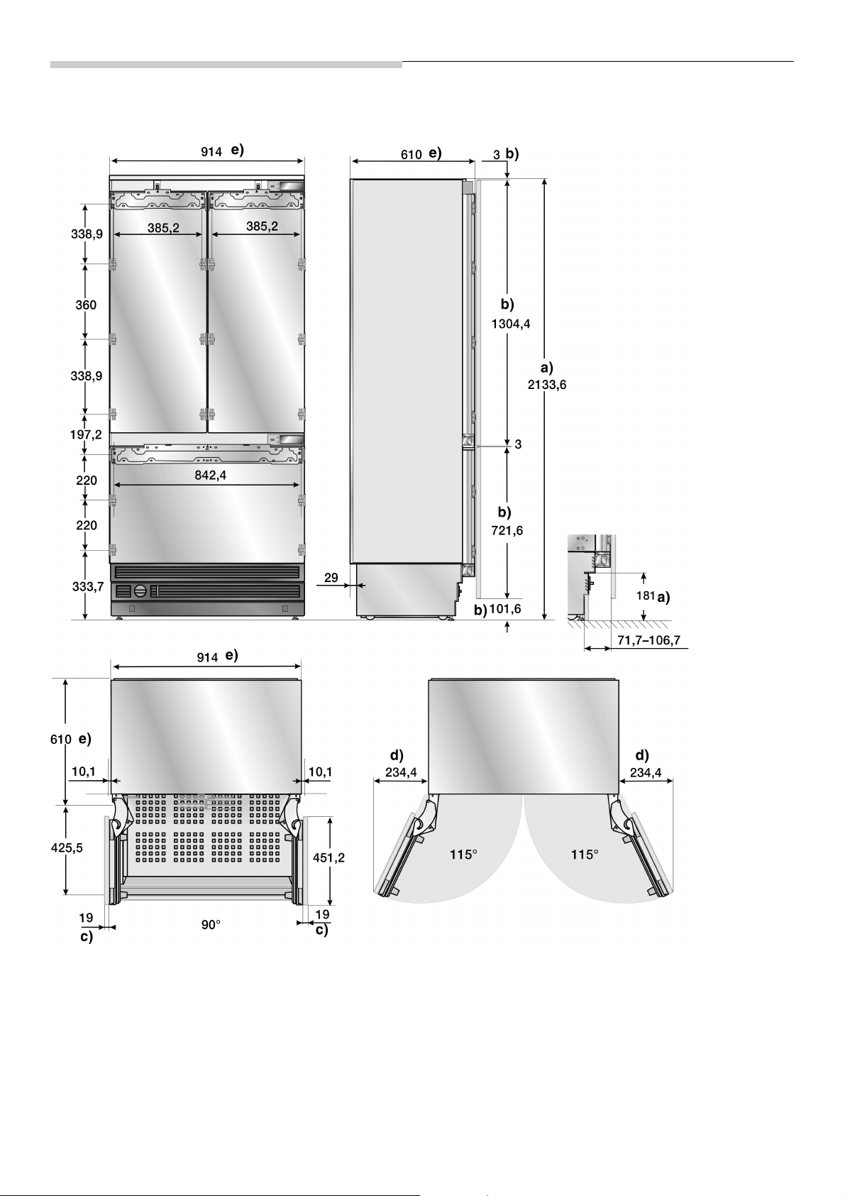
Appliance dimensions
Key:
An example is shown with a continuous furniture frontage.
a) The adjustment range of the appliance feet is
+35 mm/–13 mm.
b) Dimensions can vary
c) The thickness of the door covering can vary
8
d) This dimension can vary, depending on installation,
thickness of the furniture door to be mounted and
the neighbouring kitchen furniture.
e) Dimensions of the appliance
f) Dimensions of the furniture door

Tools and Accessories which
are needed
Scope of delivery
– Installation manual
– Operating instructions
– Installation accessories
Additional accessories
– Lateral additional heating
Necessary when the distance between
two appliances is less than 160 mm.
– Finger protection, extra long
– Connecting element for furniture doors
For connecting two furniture doors (see explanation on
page 32). It can be used for standard height furniture
doors without any preparation work.
Tools
– T20 rechargeable screwdriver
– T20 Torx screwdriver
– T20 Torx-bit magnetic holder
– 8 mm socket wrench
– Various size drills
– Fixed spanner SW 13 mm
– Adjustable spanner
– Knife with an adjustable blade
– Metal tape measure
– Angle of contact
– 60 cm and 120 cm spirit levels
– Straight edge
for stand-alone appliances min. 120 cm long
for setting up two appliances side-by-side min 200 cm
long
Miscellaneous
– Step ladder
– Trolley, wheelbarrow or sack barrow
– Hammer drill for drilling holes into the wall and floor
– Various size drills for various materials
– Wood plank, (min. 8 x 10 cm) as an alternative anti-tip
device. Length should correspond to the width of the
installation niche.
– Various size wood screws
– Thin (1.5 mm), suitable material to protect the floor
against damage (e.g. linoleum)
– Suitable material for covering and protecting the
cabinets (e.g. protective film)
– Adhesive tape
9
 Loading...