

Page 1
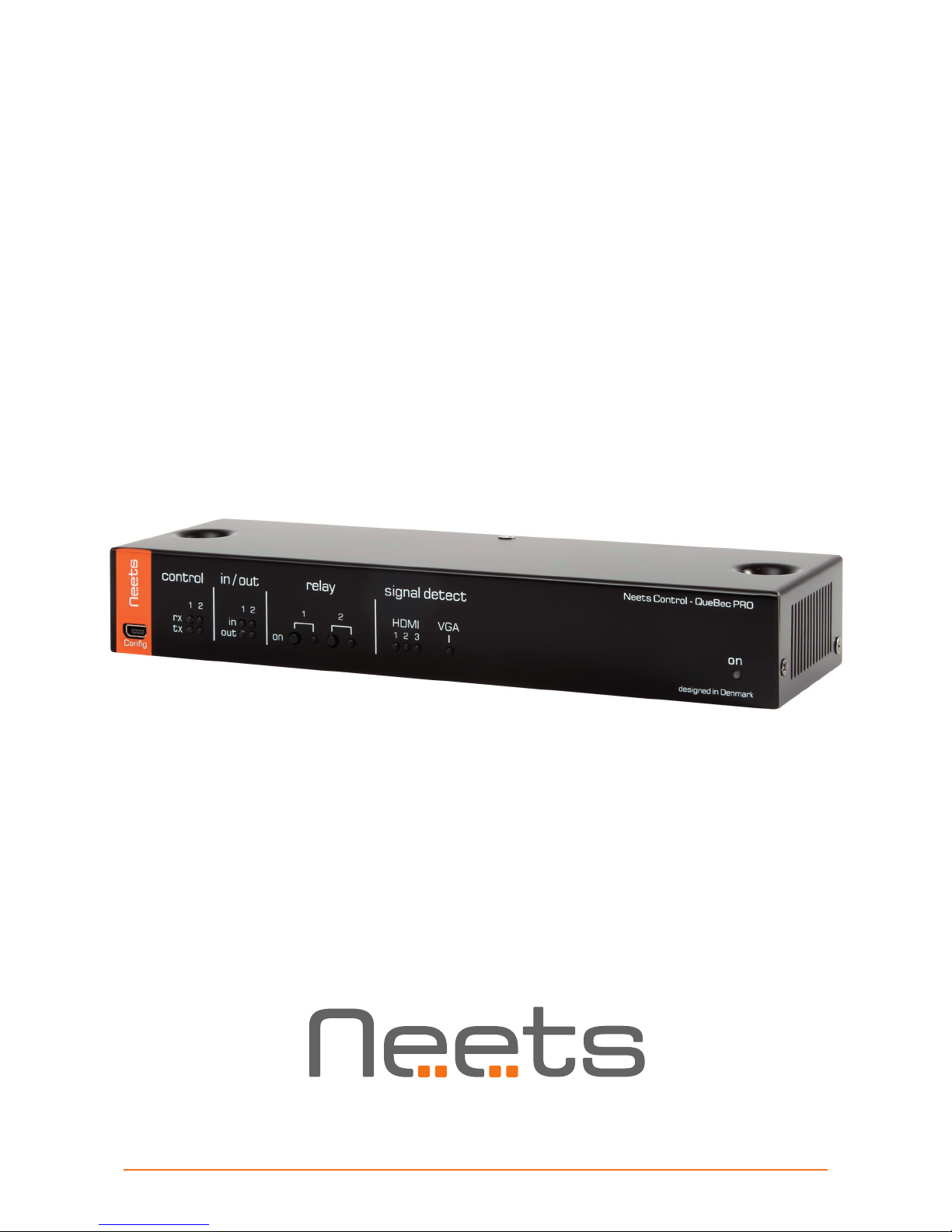
Manual QueBec Pro
Installation Manual
Page 2
Page 2 of 14
Foreword
This document describes how to install and operate the Neets Control – QueBec Pro.
COPYRIGHT - All information contained in this manual is the intellectual property and copyrighted
material of Neets. All rights are reserved. You may not allow any third party access to content,
information or data in this manual without Neets’ express written consent.
CHANGES - Neets reserve the right to change the specification and functions of this product
without prior notice.
Questions, AFTER reading this manual, can be addressed to your local distributor or:
Neets A/S
Langballe 4
8700 Horsens
Denmark
by E-Mail: [email protected]
or you may use our contact form at www.neets.dk
Revision list
This document has the following revision changes:
Author: Date Description Pages Rev
DB: 29-03-2017 First release All 1.00
DB: 18-05-2017 Specifications corrected
2, 5, 6,
8, 11, 13
2.00
DB: 24-05-2017 Specifications corrected
6
3.00
What is in the box?
When you open the box it will contain the following items:
• 1 x Neets Control – QueBec Pro
• 4 x Terminal connectors
• 2 x Screws and plugs for wall mounting Ø4 x 60 mm
• 2 x Screws for mounting on Neets Rack Shelf, M4 x 35 mm.
• 4 x Adhesive feet
• This manual
Note that PoE power injector is not included. Use the PoE Injector (Part num ber: 302-000508).
!
Page 3

Page 3 of 14
Important Safety Instructions
Caution:
Read these instructions.
Read and understand all safety and operating instructions before using the equipment.
Keep these Instructions.
The safety instructions should be kept for future reference.
Heed all warnings.
Follow all warnings and instructions marked on the equipment or in the user information.
Avoid attachments.
Do not use tools or attachments that are not recommended, as they may be hazardous.
Warning:
• This equipment should be operated only from the included power supply.
• To remove power from the equipment safely, remove all power cords from the rear of the equipment, or the
desktop power module (if detachable), or from the power source receptacle (wall plug).
• Power cords should be routed so that they are not likely to be stepped on or pinched by items placed upon or
against them.
• Do not defeat the safety purpose of a polarized or grounding-type plug. A polarized plug has two blades with one
wider than the other. A grounding-type plug has two blades and a third grounding prong. The wide blade or the
third prong is provided for your safety. If the provided plug does not fit into your outlet, consult an electrician for
replacement of the obsolete outlet.
• Unplug this apparatus during lightning storms or when unused for long periods of time.
• Refer all servicing to qualified service personnel. There are no user-serviceable parts inside. To prevent the risk of
shock, do not attempt to service this equipment yourself because opening or removing covers may expose you to
dangerous voltage or other hazards. Contact your local Neets reseller or distributor.
• If the equipment has slots or holes in the enclosure, these are provided to prevent overheating of sensitive
components inside. These openings must never be blocked by other objects.
• Do not use this equipment near water.
• To reduce the risk of fire or electric shock, do not expose this apparatus to rain or moisture and objects filled
with liquids.
• Unplug the product before cleaning. Clean only with a dry cloth and not cleaning fluid or aerosols. Such products
could enter the unit and cause damage, fire, or electric shock. Some substances may also mar the finish of the
product.
FCC Class A Notice:
This equipment has been tested and found to comply with the limits for a Class A digital device, pursuant to part
15 of the FCC Rules. Operation is subject to the following two conditions:
1. This device may not cause harmful interference.
2. This device must accept any interference received, including interference that may cause undesired operation.
The Class A limits are designed to provide reasonable protection against harmful interference when the
equipment is operated in a commercial environment. This equipment generates, uses, and can radiate radio
frequency energy and, if not installed and used in accordance with the instruction manual, may cause harmful
interference to radio communications. Operation of this equipment in a residential area is likely to cause harmful
interference, in which case the user will be required to correct the interference at his own expense.
FCC regulations state that any unauthorized changes or modifications to this equipment, not expressly approved by
the manufacturer, could void the user’s authority to operate this equipment.
The lightning bolt triangle is used to alert the user to the presence of uninsulated “dangerous
voltages” within the unit’s chassis that may be of sufficient magnitude to constitute a risk of electric
shock to humans.
The exclamation point triangle is used to alert the user to presence of important operating and
service instructions in the literature accompanying the product.
!
Page 4

Page 4 of 14
Contents
Foreword ..............................................................2
Revision list ............................................................2
What is in the box? .......................................................2
Important Safety Instructions ...............................................3
Contents ..............................................................4
Description .............................................................5
Specifications ...........................................................6
Installation .............................................................7
Connection and Controls ...................................................8
Front ...............................................................8
Back................................................................10
Automaticity input selection.................................................12
How to connect..........................................................13
PoE power supply to QueBec Pro ...........................................13
Troubleshooting..........................................................14
Error indication using LEDs ...............................................14
Page 5
Page 5 of 14
Description
Neets Control - QueBec Pro is designed to create an intelligent AV-control environment in small and
medium-sized meeting rooms or learning spaces with interactive displays or LCDs.
QueBec Pro senses the presence of image/picture, and automatically initiates room functions and
switches automatically between all HDMI/ VGA signals.
For easy installation, the QueBec Pro can be powered by PoE and can be mounted anywhere.
Function Description
• Automatic Sensing AV control system
Senses the video/picture and automatically starts up room functions
• Makes Wireless Presentation smarter
Enhance collaboration between displays, wireless presentation solutions and other AV devices
• Auto Source Selection
Latest active source is automatically selected and displayed
• HDMI Sensing and Repeater
HDMI sense works with all products and the Repeater enables longer cable drive
• VGA Video Detection
Enables Hsync detection of video signals
• Built–in 3-Port HDMI switch
Connect 3 HDMI input sources and switch between upon signal present
• Fast installation
2 all-through screw holes, Euroblock connectors and PoE makes installation fast and efficient
• 2 Bi-directional RS-232 or 4 IR port
Used for sending commands to projectors or other AV devices using serial or infrared
communication
• 2 Low-Voltage RelaysUsed for output control of relays, switches 2 General Purpose I/O ports
Used for input/output control of relays, switches and sensors
• 1 Ethernet port
Used for controlling 2 LAN devices and extension devices
• PoE powered
Power the QueBec Pro with a compliant PoE power supply or switch (PoE injector not included)
Specifications
RS-232 (Tx+Rx) or IR (controls up to 2 IR devices on each port) 2
LAN device control 2
I/O 2
Low voltage relays 2
PoE input 1
VGA loop through with signal detection 1
HDMI switch with 3 input with signal detection 1
USB port for programming 1
PIR sensor input Ye s
Light on/off Ye s
Room darkening Ye s
Screen up/down Yes
Device feedback Yes
Page 6

Page 6 of 14
Specifications
Neets Control - QueBec Pro
RS-232 / IR port
Ports 2 x bidirectional
2 x unidirectional
Baud rate 1200 – 115200 bit/sec
Data bits 7, 8
Parity Even, Odd, None
Stop bits 1, 2
IR frequency 400 Hz to 500 KHz
Connector 3 pin screw block
IR learn
IR Learn frequency 1 KHz to 150 KHz
Input / Output
Ports 2 x I/O
Input trigger low < 1VDC
Input trigger high > 4VDC
Output type Open drain
Isolated output No
Max voltage load 24 VDC
Max current 0.5 A
Connector 4 pin screw block
Relay Output
Voltage max 30 VDC
Current max 0.5 A
Connector 2 pin screw block
Network (LAN)
Speed 10 / 100 Mbit
Duplex modes Half or Full
DHCP Default off
Default IP 192.168.254.252
Default gateway 192.168.1.1
Default subnet mask 255.255.255.0
PoE input
Compliance 802.3af / 802.3at
802.3af PD mode A + B
PD Class 0 (802.3af)/4 (802.3at)
VGA input
Sense type Vertical sync (Pin 14)
Max resolution QWXGA-2048x1152
Connector VGA DE15 female plug
General
Width 218 mm
Height 37 mm
Depth 70 mm
Width 8,58 Inches
Height 2,76 Inches
Depth 1,46 Inches
Weight 0,52 kg
Shipping weight 1,0 kg
Shipping dimension 282 mm / 188 mm /
(W/D/H) 55 mm
Storage temperature -20 °C to 50 °C
Storage moisture Non-condensing
Operation temperature 0 °C to 30 °C
Operation moisture Non-condensing
Approvals
IEC/EN 61000-6-1
IEC/EN 61000-6-2
FCC Part 15, Class A
CE
HDMI switch
Input 3
Output 1
Connector HDMI type A
HDMI version 1,4
Sense type TDMS clock
(Pin 10 and 12)
HDCP support No
Video support HDTV formats up to
1080p 12bit Deep Color
DVI RGB graphics up to
1600 x 1200 @ 60Hz
Audio support Full audio input and
stereo output support
HDMI Compatible audio
interface
Product number
310-0020 QueBec Pro
Page 7
Page 7 of 14
Installation
The Neets Control – QueBec Pro is designed to be easily installed in any convenient location. It can be
placed on a desk free standing. Simply unpack the unit, mount the adhesive feet and it is ready to go.
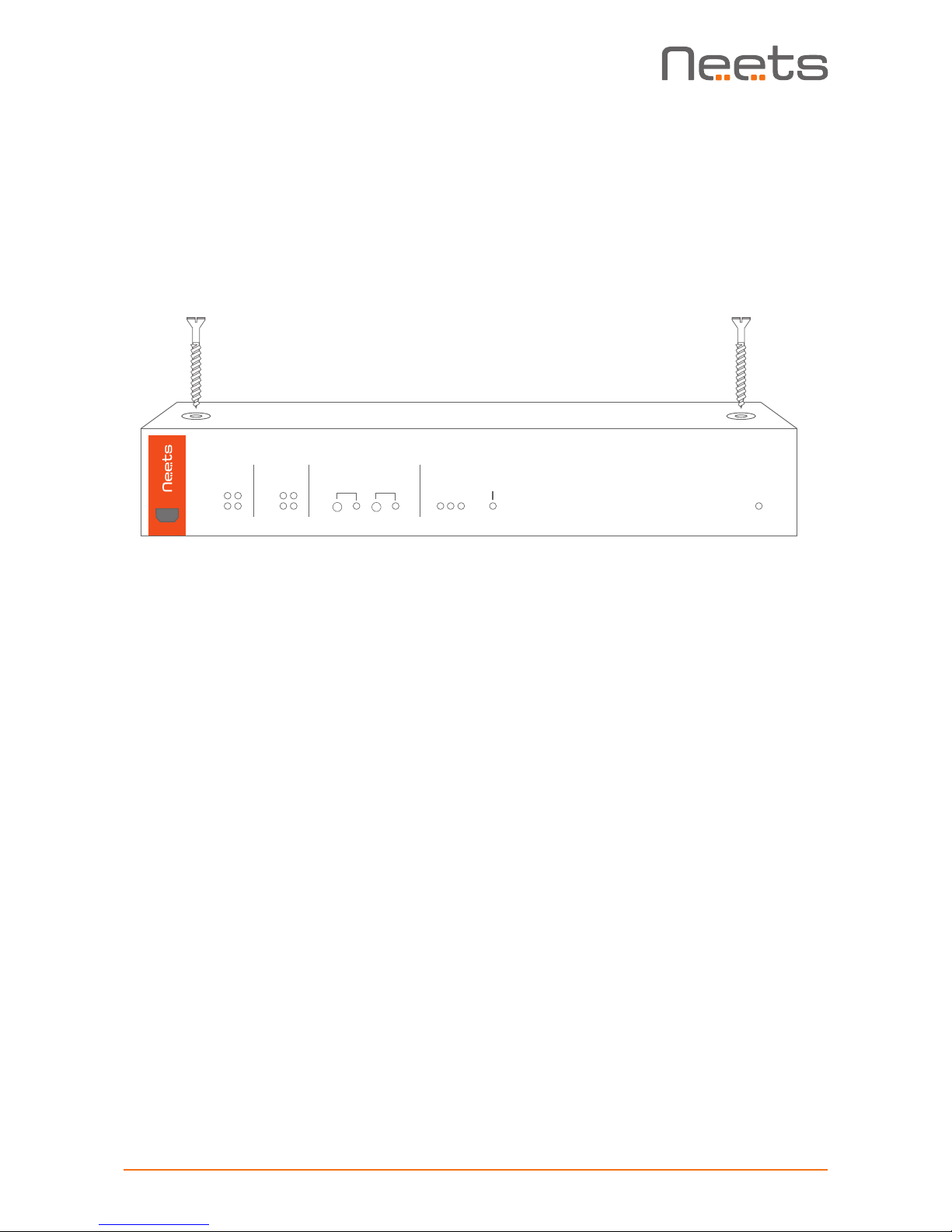
Alternatively, the unit can be mounted under a table, on a ceiling etc. with the included self-tapping
screws. Unpack the unit, place the unit on the surface where it should be mounted, and screw the
two screws through the holes in the top as shown below:
The unit also can be mounted in a 19-inch standard rack using the Neets Rack Shelf (Part number: 306-0017). See separate manual for installation instructions.
Designed in Denmark
Neets Control -
QueBec Pro
on
control
config
21
tx
rx
in / out
1 2
in
out
relay signal detect
on
1
2
HDMI VGA
1
3
2
Page 8
Page 8 of 14
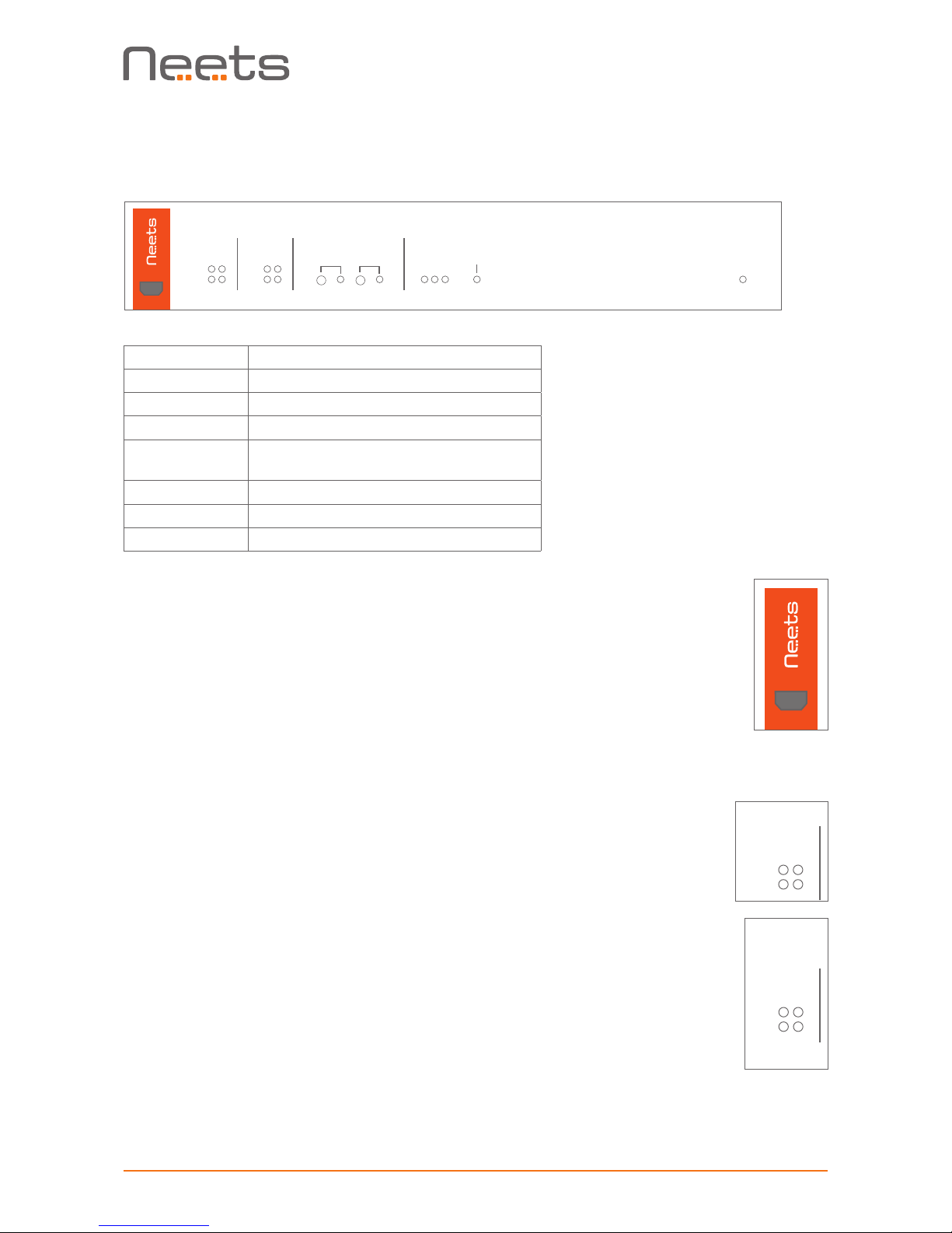
Front USB Configuration
The USB port is used exclusively for configuring the QueBec Pro from the
Neets Project Designer software. It can’t be used to control any external
devices.
The QueBec Pro must be powered by PoE supply that complies with IEEE
802.3 and 802.3at, type 1 in order to configure it by USB.
The USB connector for connecting to the QueBec Pro is “mini USB B 5P”. You
can buy this cable on the web (select a USB A to Mini USB B 5P).
RS-232 Status Indication
The RS-232 status LED displays the current status of the RS-232 ports.
The LEDs illuminate when there is active communication on the port.
IO Status Indication
The IO status LED displays current status of the I/Os.
When an IO is configured as input, the yellow LED marked “in” will illuminate
when the input is high and turn off when the input is low. The green LED
marked “out” will remain off.
When an IO is configured as output, the green LED marked “out” will
illuminate when the output is high and turn off when the output is low. The
yellow LED marked “in” will remain off.
Connection and Controls
Front
Number Description
1 USB configuration input
2 RS-232 status indication
3 IO status indication
4 Relay control button / and status
indication
5 HDMI /VGA signal detection status
6 VGA signal detection status
7 Power and error indication
1 3 4 5 62 7
Designed in Denmark
Neets Control -
QueBec Pro
on
control
config
21
tx
rx
in / out
1 2
in
out
relay signal detect
on
1
2
HDMI VGA
1
3
2
Designed in Denmark
Neets Control -
QueBec Pro
on
control
config
21
tx
rx
in / out
1 2
in
out
relay signal detect
on
1
2
HDMI VGA
1
3
2
Neets Control -
QueBec Pro
on
control
21
tx
rx
in / out
1 2
in
out
relay signal detect
on
1
2
HDMI VGA
1
3
2
Designed in Denmark
Neets Control -
QueBec Pro
on
in / out
1 2
in
out
relay signal detect
on
1
2
HDMI VGA
1
3
2
Page 9
Page 9 of 14
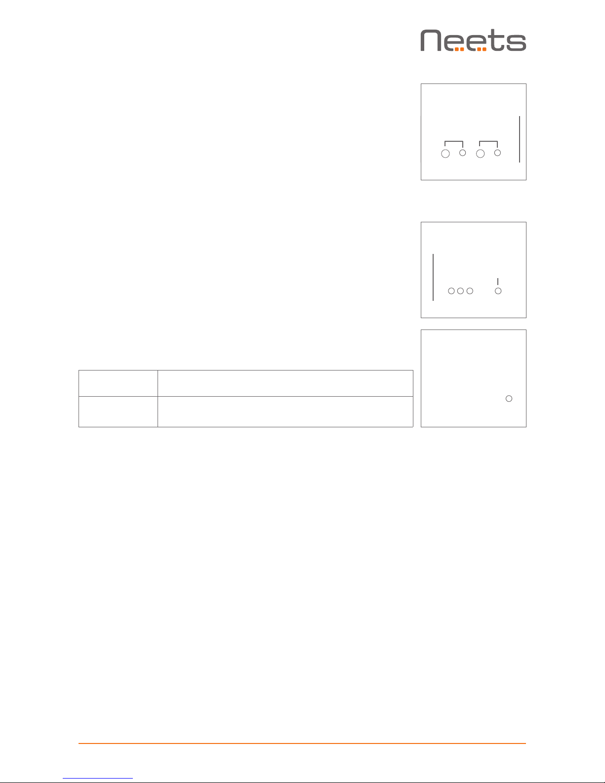
Relay Control and Indication
The two test buttons are used to test the built-in relay function.
The test buttons are intended for use during installation to control
functionality of connected devices. The LEDs will indicate if the relay
is activated (green) or not activated (off) during use of the test buttons. They will also illuminate when the relays are controlled by the
project in the QueBec Pro.
Be aware that you can activate multiple relays at the same time and
damage connected equipment if not carefull.
VGA and HDMI signal detection
The led indicate if a signal on the input is detected or not. If the led light
is green this indicate that a signal are present.
Power and error indication
The “on” LED will show the current status of the controller.
Green Neets Control – QueBec Pro is on and running
normally
Flashing red The Neets Control – QueBec Pro is in error mode,
se section “Error indication” on page 14 for details
Designed in Denmark
Neets Control -
QueBec Pro
on
signal detect
HDMI VGA
1
3
2
Designed in Denmark
Neets Control -
QueBec Pro
on
Designed in Denmark
Neets Control -
QueBec Pro
on
relay
signal detect
on
1
2
HDMI VGA
1
3
2
Page 10
Page 10 of 14
Back
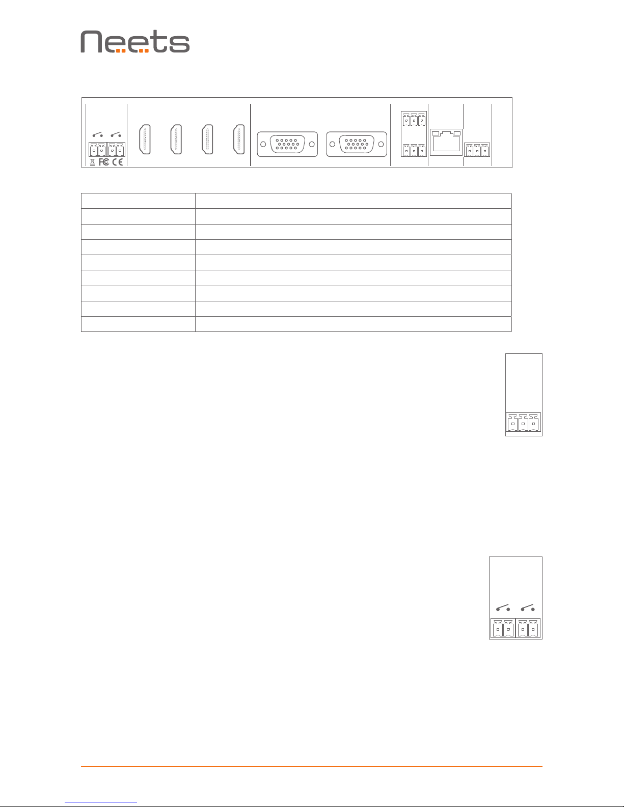
Number Description
1 2 x potential-free relays
2, 3, 4, HDMI input 1 – 3
5 HDMI output
6 VGA input
7 VGA output
8 2 x bi-directional RS-232 or IR transmitter
9 RJ-45 Network (LAN) connector with PoE input
10 Digital I/O
2 1 3 4 5 6 7 8 9 10
IO Connectors
The QueBec Pro has two I/O (Inputs/Outputs), which can be configured as
output or input. Each I/O is available for connection to a PIR (movement)
sensor, keyboard lock, relays or for other compatible uses. The ports are
not potential free; you may need external relays to prevent ground loops
depending on your application. Or use the relays on the QueBec Pro.
When used as outputs, the I/O ports are active low. When activated, the
I/O ports are tied to GND through a FET transistor (also called open drain/
collector function). Each I/O can draw up to 24VDC/500mA.
When used as inputs, the applied voltage must be below 1 VDC to be
accepted as LOW, and above 4 VDC (but below 24 VDC) to be accepted
as HIGH. The inputs are default HIGH and must be connected to ground in
order to change state.Relays
Relays
Relays are used when a external control is needed where there must be
potential free connection between the control and the QueBec Pro.
The relays are normally open types. This means that the terminals are not
connected when the relay is off.
LAN
PoE IN
PN: 312-0020
RS-232/IR
G
T2
R2
GT1R1
Relays
www.neets.dk
I/O
G
1
2
in
1 2
HDMI
outin 1 in 2 in 3 out
VGA
PN: 312-0020
www.neets.dk
I/O
G
1
2
LAN
PoE IN
PN: 312-0020
RS-232/IR
GT1R1
Relays
www.neets.dk
I/O
G
1
2
in
1 2
HDMI
outin 1 in 2 in 3 out
VGA
extension
Page 11
Page 11 of 14
LAN
PoE IN
PN: 312-0020
RS-232/IR
G
T2
R2
GT1R1
www.neets.dk
I/O
G
1
2
RS-232 connectors
The onboard RS-232 ports T1 + R1, T2 + R2 can be used for two-way
communication with external RS-232 compatible devices. Alternatively, all
Tx ports can act as IR transmitter ports.
All of the RS-232/IR ports can be configured in the Neets Project Designer
software either as RS-232 or as IR emitter.
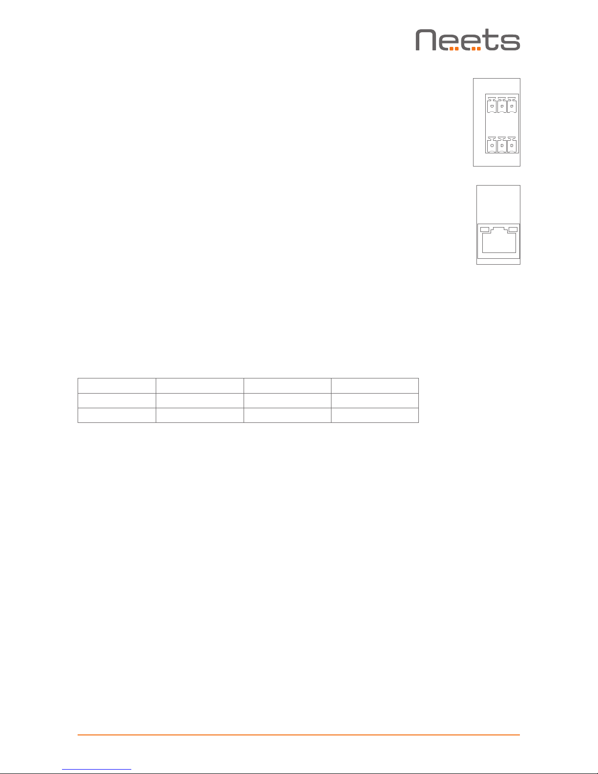
LAN connectors with PoE functionality
The LAN connector is used to connect the QueBec Pro to the local area
network. The QueBec Pro has Power over Ethernet functionality built into
both the LAN interface connectors.
You must connect the QueBec Pro to your LAN if you are using any of the
LAN features of the product. The ports features auto MDI-X which means
that you can connect the LAN ports directly to other devices without the
need for a LAN switch.
The connector marked with PoE IN is used to power up the entire control system. To power the QueBec Pro, use a PoE enabled switch which
complies with IEEE802.3af. Or you can use the PoE Injector (Part number
302-000508).
There are two LEDs on each connector with the following indication:
Color Off On Blink
Yellow No Link Link Activity
Green 10 Mbit 100 Mbit
LAN
PoE IN
PN: 312-0020
www.neets.dk
I/O
G
1
2
Page 12
Page 12 of 14
Automaticity input selection
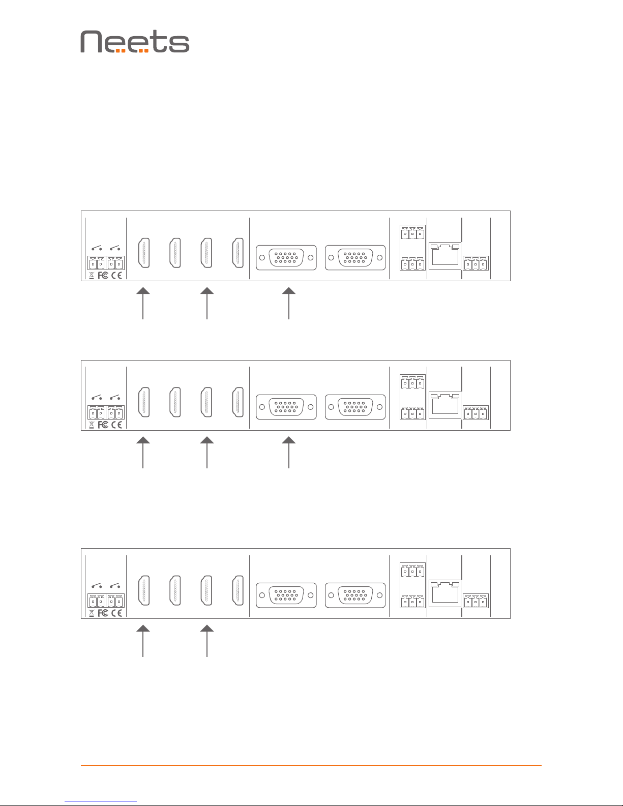
The QueBec Pro has a built-in automatically input selection mechanism that ensure that the
latest active input connected to the Quebec Pro will be selected as the active one.
The way QueBec Pro works can be compared to a LIFO (Last in, first out) buffer. The only difference is that if an input no longer is active it will be removed from the “LIFO buffer”.
Connected order
Fallback order
If the VGA input no longer is active it is simply removed from the “buffer” giving a new fallback
order like this.
The QueBec Pro make sure that when changing between VGA and HDMI input the device being
controlled will have the right input selected.
If you bypass the automaticity input selection and select an input that is not active, this will be
added to the “LIFO buffer” the same way as if an active signal is detected. In case an inactive
input is manual selected and another input become active the system will jump to this input.
LAN
PoE IN
PN: 312-0020
RS-232/IR
G
T2
R2
GT1R1
Relays
www.neets.dk
I/O
G
1
2
in
1 2
HDMI
outin 1 in 2 in 3 out
VGA
LAN
PoE IN
PN: 312-0020
RS-232/IR
G
T2
R2
GT1R1
Relays
www.neets.dk
I/O
G
1
2
in
1 2
HDMI
outin 1 in 2 in 3 out
VGA
LAN
PoE IN
PN: 312-0020
RS-232/IR
G
T2
R2
GT1R1
Relays
www.neets.dk
I/O
G
1
2
in
1 2
HDMI
outin 1 in 2 in 3 out
VGA
1
3
2
2
2
1
3
1
Page 13
Page 13 of 14
How to connect
PoE power supply to QueBec Pro
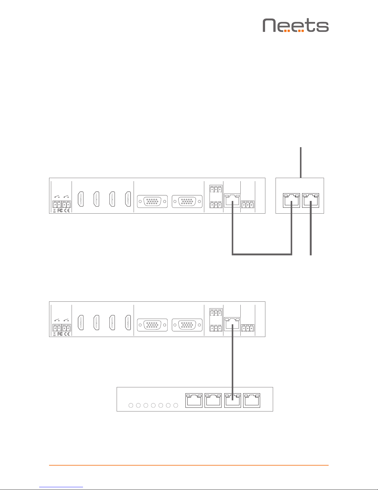
To power up the QueBec Pro the LAN connector marked with PoE IN should be connected to a
compliant PoE power supply or switch (PoE injector not included). Connect the PoE Injector LAN
connector marked “POE” to the QueBec Pro LAN connector marked PoE IN with a RJ45 terminated LAN cable.
Connect the PoE Injector connector marked “LAN” to the local network if networking features are
required. Connect the PoE Injector to mains power supply using the supplied cable:
Alternatively the QueBec Pro can be connected to a PoE enabled switch:
LAN
PoE IN
PN: 312-0020
RS-232/IR
G
T2
R2
GT1R1
Relays
www.neets.dk
I/O
G
1
2
in
1 2
HDMI
outin 1 in 2 in 3 out
VGA
LAN
PoE IN
PN: 312-0020
RS-232/IR
G
T2
R2
GT1R1
Relays
www.neets.dk
I/O
G
1
2
in
1 2
HDMI
outin 1 in 2 in 3 out
VGA
PoE
LAN
LAN in
230 V in
PoE
LAN
PoE
LAN
Page 14
Page 14 of 14
Troubleshooting
Error indication using LEDs
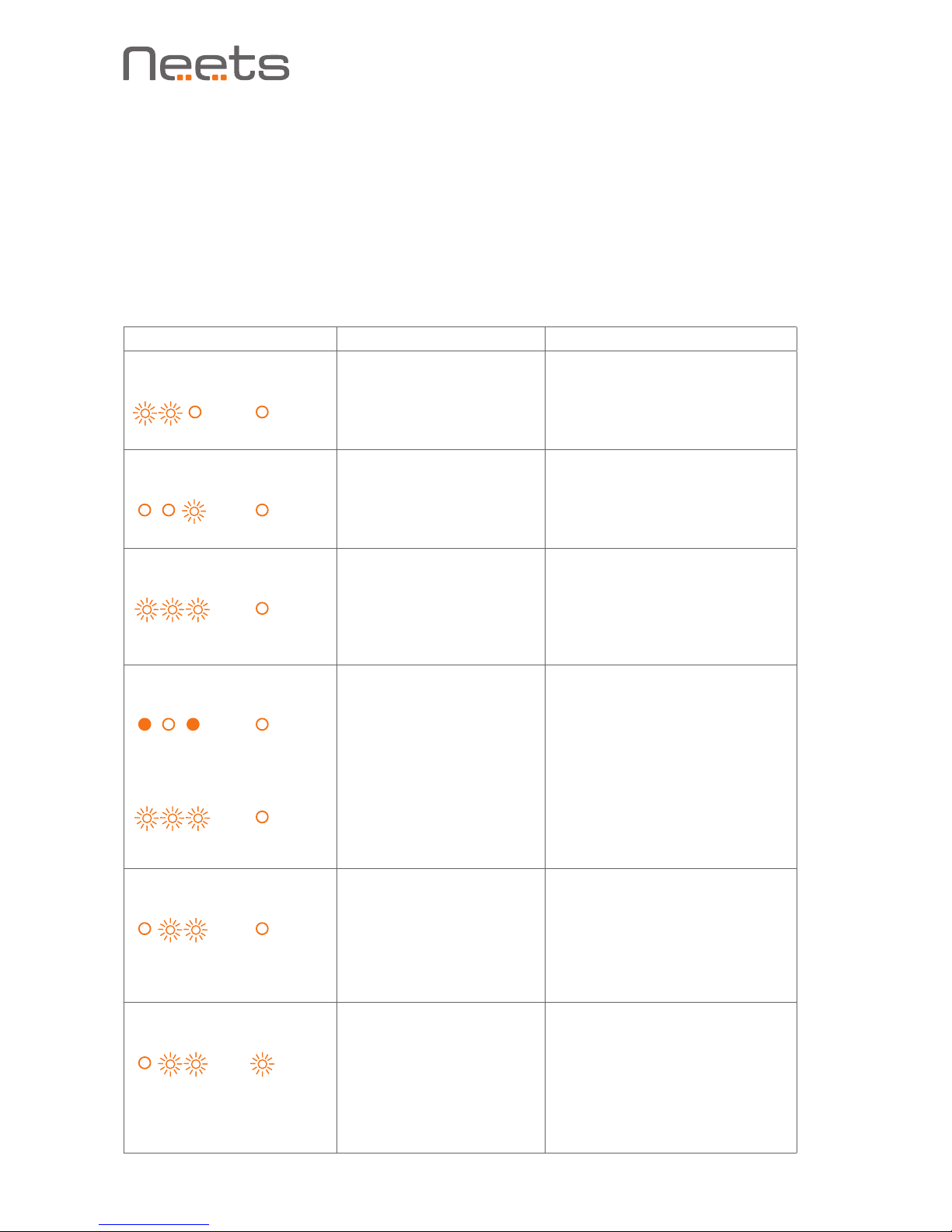
If there is a fault in either the configuration or the QueBec Pro unit, this will be indicated on the
front LED indicators.
In all error modes the power LED will flash red alternating with the IO LEDs. The alternating IO
LEDs will indicate type of error see below list:
LED shows Description Solution
Unexpected Error
o
Turn off the power to the
control system for 20 sec
before turning the power on
again
Error in serial number
o
You need to return the unit to
Neets or your local dealer for
replacement/repair
No project found on the
control system or unable
to start the project
o
Try to upload the project again
o
Alternatively, there can be
a problem in the project you
have uploaded. In this case, try
uploading an empty project and
see if this works
Systems are resuming
factory default settings
o
When pressing Switch 1 and 2
during power on, the system
will delete current settings and
resume factory default.
This method is only intended to
be used, if the control system
locks up and enters ’’Unexpected Error’’
No contact to Neets
extension unit
o
Check to confirm that the serial
number used in Project Designer
matches the Neets extension unit
o
Check the network or RS-232
connection from the control
system to the Neets extension
unit
Wrong firmware version in
Neets extension unit
o
The Neets extension unit has a
different firmware than the one
in the control system
o
Please upgrade the firmware by
plugging in the USB cable from
the Neets extension unit into
a PC running Project Designer
and follow the instructions
HDMI VGA
1 2 3 I
HDMI VGA
1 2 3 I
HDMI VGA
1 2 3 I
HDMI VGA
1 2 3 I
HDMI VGA
1 2 3 I
HDMI VGA
1 2 3 I
HDMI VGA
1 2 3 I
↓
 Loading...