


Installation guide
Neets Touch Panel™

Thank you!
Thank you for including the Neets Touch
Panel as part of the user interface strategy
for your customer.

Specifications
Physical Dimensions:
H: 120 mm
W: 180 mm
D: 41,4 mm
In wall: 25,4 mm
On wall: 17,7 mm
Shipping dimensions:
65 mm x 280 mm x 240 mm (HxWxD)
Weight:
Product: 0,33 Kg
Wall Bracket: 0,175 Kg
Shipping: 0,85 Kg
Connections:
RJ45 with POE – For both Power and Ethernet
communication
Switches:
Pen hole switch:
1: Access to Admin settings
2: Factory Reset switch
3: For FW upgrade only
Touch Screen:
5-point capacitive touch screen
Scratch resistant glass-on-glass touch screen
Display:
7” IPS Display,
Resolution: 1024x595 pixels
Brightness: 350 nits (cd/m2)
Sensors:
Proximity sensor – For automatic display activation
Ambient Light sensor – For automatic backlight dimming
Power:
Power Over Ethernet (POE), IEEE802.3af, 48V (PoE injector
not included)
Environment:
Operating Temp: 0 to 40 C / 32 to 104 F
Storage Temp: 0 to 60 C / 32 to 140 F
Operation moisture: Humidity: 10% to 90% RH
Compliancy:
CE, FCC
Doc. 313-001-001 Rev. 3
2

What’s in the box
3
Wall mount bracket
7” Touch Panel
Cloth

Ejector pin for
menu settings
4 x Screws
USB OTG adapter (for application
and firmware upgrade)
4 x Wall plugs
4

Front
Proximity
sensor
Ambient light
sensor
5
1 120 mm
1 180 mm
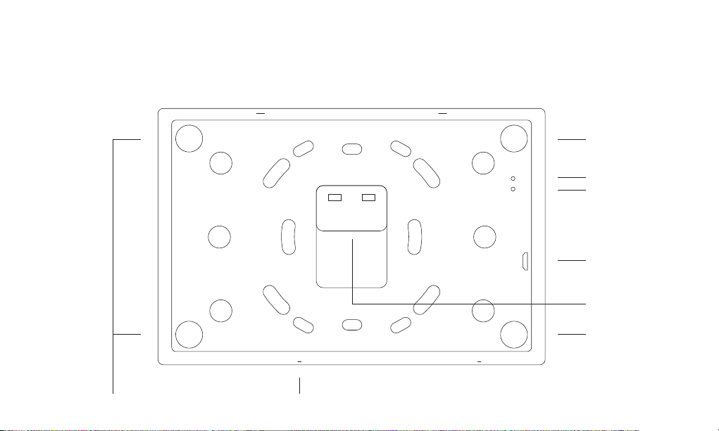
Back
Magnet
Factory Reset
Firmware upgrade
USB
LAN/POE
Magnet
Magnets Settings button
6

Steps
1 Touch Panel position
2 Bracket details
3 Mounting the bracket
4 Connect LAN/PoE
7
5 Mount Touch Panel on bracket
6 Connect PoE injector
7 First start up
1
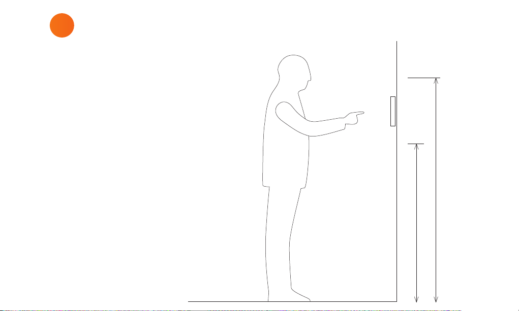
Touch Panel position
The Touch Panel is designed to wall
mount in landscape orientation, and
depending on how tall the users are we
recommend locating the center of the
touch panel between 145 cm. – 165 cm.
(57” – 65”) above the finish floor.
165 cm / 65 in.
145 cm / 57 in.
8

2
Bracket details
The Touch Panel is designed to mount
into a 1- or 2-gang back box in EU, US or
DK standards or can be mounted without
a back box.
When using EU and US standards use
the threads that are already in the back
box and secure the bracket with fitting
screws.
When using a DK standard back box use
the holes marked with “W” for mounting
directly on the wall.
To mount the Touch Panel without back
box use holes marked with “W”.
9

The numbers on the bracket
refers to the back box it is
intended for.
1
EU 1-gang back box
2
EU 2-gang back box
3
US 1-gang back box
4
US 2-gang back box
4
W W
A
W W
2
1
2
3
4
2
1
2
A
Holes for mounting
W
directly into the wall
Alignment holes –
A
do not use these for screws
34
4
10

3
Mounting the bracket
When mounting the Touch Panel into a
EU/US back box follow the steps below.
In case you are not mounting on a EU/US
back box skip step 1.
Before you start make sure the wall is
even to prevent distorting the bracket.
Mount the bracket onto the back box
1
using the screws and screw holes for the
specific type of back box (see page 10)
2
Level the bracket on the wall
(When mounting onto a back box do this
before tightening the screws)
Mark the center of the W-holes in the
3
bracket
11
Remove the bracket again
4
Drill and insert wall plugs
5
Mount the bracket and tighten the screws
6
into the wall

12

4
Connect LAN / PoE
Connect the PoE cable from the wall
to the Touch Panel.
Note: PoE is not included, but you can
use the PoE Injector (Part number
302-000508).
13

5
Mount Touch Panel on bracket
Place the Touch Panel onto the bracket.
Make sure it is placed correctly and
the alignment holes are free to fix the
Touch Panel to all four magnets.
14

6
Connect PoE injector
Power outlet
P
O
E
L
A
N
15
LAN switch

7
First start up
The Touch Panel will automatically
power on when power is applied.
Wait for the unit to start up and
follow the instructions.
For a complete configuration guide
please go to:
www.neets.dk/products/touchpanels/155
You will find the instructions for
firmware updates the same place.
16

Removing the Touch Panel
Using two hands grasp on each
side of the Touch Panel and pull
straight out from the wall.
17

Warning
FCC Class B Compliance Notice
Unplug t his appar atus during l ightning st orms or when u nused for lon g
periods of time. Refer alle servicing to qualified service personnel. There
are no us er-servi ce-able par ts inside . To prev ent the risk of s hock, do not
attempt to service this equipment yourself because opening or removing
covers may expose you to dangerous voltage or other hazards. Contact
your local Neets reseller or distributor. If the equipment has slots or holes
in the en closure, t hese are pro vided to pre vent overhe ating of sens etive
components inside. These openings must never be blocked by other ob-
ject s. Do not use e quipment ne ar water. To reduce t he risk of fir e or electri c
shock , do not expo se this appa ratus to ra in or moistur e and objec ts filled
with li quids. Unpl ug the produ ct before cl eaning. Cle an only with a d ry cloth
and not c leaning fl uid or aeroso ls. Such pro ducts coul d enter the uni t and
cause d amage, fi re or electr ic shock. So me substa nces may also m ar the
finis h of the produ ct.
Caution
Read th ese instr uctions . Read and unde rstand a ll safety a nd operatin g
instructions before using the equipment. Keep these instructions. The
safe ty instru ctions sho uld be kept for f uture refe rence. Heed a ll warning s.
Follow a ll warning s and instru ctions ma rked on the eq uipment or in t he
user information. Avoid attachments. Do not use tools or attachments that
are not recommended, as they may be hazardous.
This equipment has been tested and found to comply with the limits for a Class
B digital device, pursuant to part 15 of the FCC Rules. These limits are designed
to provide reasonable protection against harmful interference in a residential
installation. This equipment generates, uses and can radiate radio frequency
energy and, if not installed and used in accordance with the instructions, may
cause harmful interference to radio communications. However, there is no
guarantee that the interference will not occur in a particular installation. If this
equipment does cause harmful intereference to radio or television reception,
which can be determined by turning the equipment off and on, the user is
encouraged to try to correct the interference by one or more of the following
measures:
1. Reorient or relocate the receiving antenna.
2. Increase the seperation between the equipment and receiver.
3. Connect the equipment into an outlet on a circuit different from that to
which the receiver is connected.
4. Consult the dealer or an experienced radio/TV technician for help.
This device complies with part 15 of FCC rules. Operation is subject to two
conditions.
1. This device may not cause harmful interference.
2. This device must accept any interference received, including interference
that may cause undesired operation.
Change or modifications that are not expressly approved by the manufacturer
could void the user’s authority to operate the equipment.

Learn more at neets.dk
Visit our website neets.dk for additional information
about the product and the latest firmware.
Neets A/S | Langballe 4, 8700 Horsens, Denmark | +45 75 666 099 | sales@neets.dk | www.neets.dk
 Loading...