


Installation guide
Neets Touch Panel 10”

Thank you!
Thank you for including the Neets Touch
Panel as part of the user interface strategy
for your customer.

Specifications
Physical Dimensions:
H: 169 mm
W: 246 mm
D: 41,4 mm
In wall: 25,4 mm
On wall: 16,5 mm
Shipping dimensions:
59 mm x 291 mm x 216 mm (HxWxD)
Weight:
Product: 0,56 Kg
Wall Bracket: 0,175 Kg
Shipping: 1,1 Kg
Connections:
RJ45 with POE – For Power and Ethernet communication
Micro USB – For application and firmware upgrade only
Switches:
Pen hole switch:
1: Access to Admin settings
2: Factory Reset switch
3: For FW upgrade only
Touch Screen:
5-point capacitive touch screen
Scratch resistant glass-on-glass touch screen
Display:
10 IPS Display,
Resolution: 1280x800 pixels
Brightness: 350 nits (cd/m2)
Sensors:
Proximity sensor – For automatic display activation
Ambient Light sensor – For automatic backlight dimming
Power:
Power Over Ethernet (POE), IEEE802.3af, 48V
Environment:
Operating Temp: 0 to 40 C / 32 to 104 F
Storage Temp: 0 to 60 C / 32 to 140 F
Operation moisture: Humidity: 10% to 90% RH
Compliancy:
CE, FCC
Doc. 313-003-003 Rev. 1
2

What’s in the box
10” Touch Panel
3
Wall mount bracket
Cloth

Ejector pin for
menu settings
4 x Screws
USB OTG adapter (for application
and firmware upgrade)
4 x Wall plugs
4

Front
5
Ambient light
sensor
1 246 mm
Proximity
sensor
1 169 mm

Back
Firmware upgrade
Magnet
USB
LAN/POE
Magnet
Magnets Settings button
Factory Reset
6

Steps
1 Touch Panel position
2 Bracket details
3 Mounting the bracket
4 Connect LAN/PoE
7
5 Mount Touch Panel on bracket
6 Connect PoE injector
7 First start up
1
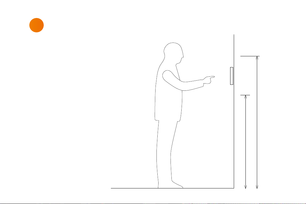
Touch Panel position
The Touch Panel is designed to wall
mount in landscape orientation, and
depending on how tall the users are we
recommend locating the center of the
touch panel between 145 cm. – 165 cm.
(57” – 65”) above the finish floor.
165 cm / 65 in.
145 cm / 57 in.
8

2
Bracket details
The Touch Panel is designed to mount
into a 1- or 2-gang back box in EU, US or
DK standards or can be mounted without
a back box.
When using EU and US standards use
the threads that are already in the back
box and secure the bracket with fitting
screws.
When using a DK standard back box use
the holes marked with “W” for mounting
directly on the wall.
To mount the Touch Panel without back
box use holes marked with “W”.
9

The numbers on the bracket
refers to the back box it is
intended for.
1
EU 1-gang back box
2
EU 2-gang back box
3
US 1-gang back box
4
US 2-gang back box
4
W W
A
W W
2
1
2
3
4
2
1
2
A
Holes for mounting
W
directly into the wall
Alignment holes –
A
do not use these for screws
34
4
10

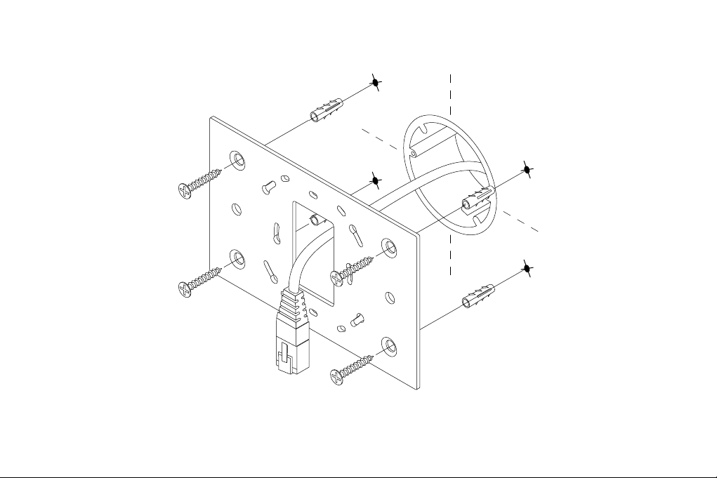
3
Mounting the bracket
When mounting the Touch Panel into a
EU/US back box follow the steps below.
In case you are not mounting on a EU/US
back box skip step 1.
Before you start make sure the wall is
even to prevent distorting the bracket.
Mount the bracket onto the back box
1
using the screws and screw holes for the
specific type of back box (see page 10)
2
Level the bracket on the wall
(When mounting onto a back box do this
before tightening the screws)
Mark the center of the W-holes in the
3
bracket
11
Remove the bracket again
4
Drill and insert wall plugs
5
Mount the bracket and tighten the screws
6
into the wall
12

4
Connect LAN / PoE
Connect the PoE cable from the wall
to the Touch Panel.
13

5
Mount Touch Panel on bracket
Place the Touch Panel onto the bracket.
Make sure it is placed correctly and
the alignment holes are free to fix the
Touch Panel to all four magnets.
14

6
Connect PoE injector
15
Power outlet
P
O
E
L
A
N
LAN switch

7
First start up
The Touch Panel will automatically
power on when power is applied.
Wait for the unit to start up and
follow the instructions.
For a complete configuration guide
please go to:
www.neets.dk/products/touchpanels/
You will find the instructions for
firmware updates the same place.
16

Removing the Touch Panel
Using two hands grasp on each
side of the Touch Panel and pull
straight out from the wall.
17

Warning
This equipment should be operated only from the included power supply. To remove power
from the equipment safely, remove all power cords from the rear of the equipment, or the
desktop power module (if detachable), or from the power source receptacle (wall plug).
Power co rds should be r outed so tha t they are not l ikely to be ste pped on or pin ched by
items placed upon or against them.
Do not def eat the saf ety purpo se of a polariz ed or ground ing-type plu g. A polariz ed plug
has tw o blades wit h one wider tha n the other. A gr ounding-ty pe plug has t wo blades and a
third g rounding pr ong. The wide b lade or the th ird prong is pr ovided for y our safet y. If the
provid ed plug does n ot fit into you r outlet, c onsult an ele ctrician f or replacem ent of the
obsole te outlet . Unplug this a pparatus d uring light ning storm s or when unuse d for long
periods of time.
Refer all servicing to qualified service personnel. There are no user-serviceable parts
inside . To prevent the ris k of shock, do n ot attempt t o service t his equipme nt yoursel f
becau se opening or r emoving cove rs may expos e you to
dangerous voltage or other hazards. Contact your local Neets reseller or distributor.
If the equipment has slots or holes in the enclosure, these are provided to prevent
overheating of sensitive components inside. These openings must never be blocked by
other objects.
Do not use this equipment near water.
To reduce th e risk of fire o r electric s hock, do not e xpose thi s apparat us to rain or moi sture
and obje cts fille d with liqui ds.
Unplug t he product b efore clea ning. Clean o nly with a dr y cloth and no t cleaning fl uid or
aerosols. Such products
could ent er the unit a nd cause dama ge, fire, or e lectric s hock. Some s ubstance s may also
mar the f inish of the p roduct.
Caution
Read th ese instru ctions. Re ad and under stand all s afety an d operating i nstruct ions befor e
using the equipment. Keep these Instructions.
The saf ety instr uctions s hould be kept fo r future re ference. He ed all warni ngs. Follow
all warnings and instructions marked on the equipment or in the user information. Avoid
attachments. Do not use tools or attachments that are not recommended, as they may
be hazardous.
FCC Warning
This device complies with Part 15 of the FCC Rules. Operation is subject to the following two
conditions: (1) This device may not cause harmful interference, and (2) this device must accept
any interference received, including interference that may cause undesired operation.
NOTE 1: This equipment has been tested and found to comply with the limits for a Class
B digital device, pursuant to part 15 of the FCC Rules. These limits are designed to provide
reasonable protection against harmful interference in a residential installation. This equipment
generates, uses and can radiate radio frequency energy and, if not installed and used in
accordance with the instructions, may cause harmful interference to radio communications.
However, there is no guarantee that interference will not occur in a particular installation.
If this equipment does cause harmful interference to radio or television reception, which can be
determined by turning the equipment off and on, the user is encouraged to try to correct the
interference by one or more of the following measures:
- Reorient or relocate the receiving antenna.
- Increase the separation between the equipment and receiver.
-Connect the equipment into an outlet on a circuit different from that to which the receiver is
connected.
-Consult the dealer or an experienced radio/TV technician for help.
NOTE 2: Any changes or modifications to this unit not expressly approved by the party respon-
sible for compliance could void the user’s authority to operate the equipment.

Learn more at neets.dk
Visit our website neets.dk for additional information
about the product and the latest firmware.
Neets A/S | Langballe 4, 8700 Horsens, Denmark | +45 75 666 099 | sales@neets.dk | www.neets.dk
 Loading...