

Page 1

N1283-12
1310nm Transmitter
User Manual
XIAMEN NAGASIMA ELECTRONIC EQUIPMENT CO LTD
Page 2

1310nm Transmitter
1. FEATURE
•
High-quality DFB AOI laser unit as the optical source
• Pre-distortion circuit
• RF driving amplifying module ensuring the high quality and performance
• Modularization design and high-efficient switch power supply
• CPU monitor control the working statues, Cut off the optical power automatically when abnormal
• CPU monitor control the working statues
• LED indicates the working status and the alarm message
• Working bandwidth 47-862MHz, Net-management design
• Operating status alarm and parameter indication
2. Block Diagram
Figure 1
NAGASIMA ELECTRONIC EQUIPMENT www.neecatv.com
Tel :+86-592-5771182 Fax: +86-592-5032560 Email: [email protected]
2
Page 3
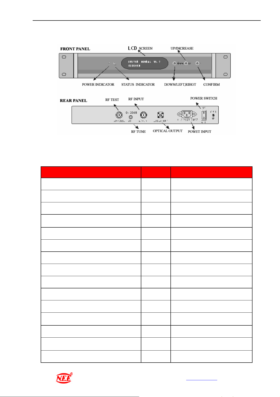
3. PANEL & REAR PANELS
1310nm Transmitter
Figure 2
4. SPECIFICATION
ITEM UNIT PARAMETER
Optical Power mW 10
Optical Wave length nm 1310±20
Optical Fiber Connector / FC/APC
Operating Frequency MHz
RF Input Level dBμV 78±6
Flatness In Band dB ±0.75
Input Impedance ohms 75
Input Return Loss dB ≥16
Composite Triple Beat dB 65
Composite Second Order dB 60
47~862
CNR dB 51
Power Supply(50Hz) VAC
Power Consumption W 24
Operation Temperature ℃
Dimension mm 483×381×44
NAGASIMA ELECTRONIC EQUIPMENT www.neecatv.com
Tel :+86-592-5771182 Fax: +86-592-5032560 Email: [email protected]
100~265
0~45
3
Page 4

1310nm Transmitter
5. Operation and Alarm Display
Insert power cord, front panel LED display“Please wait…”, POWER indicator become red and ALARM
indicator become yellow(orange red), system begin self-checking. 8 seconds later,system is set to normal working
station and the LED panel display “System normal” as following picture, ALARM Indicator become green。
The control system monitor the working status of laser unit, display the status and indicate alarming and failure
details.
Press the DOWN/ UP function button, the LED panel can display the key working parameters.
① Transmitter Model:
② Transmitter Serial No:
③ Power supply monitor: the control system constantly monitor the power supply to the Laser
Unit, when power supply is normal, the LED panel can display the voltage values; the normal range
for 5V power from 4.5V to 5.0V 10% bias, for 24V power from 18V to 28V. Whenever any Voltage
go out of the range, the ALARM indicator become blinking yellow and automatically shut down the
power supply to laser unit.
-5V POWER
-5.1V
④ Laser unit temperature monitor:the laser unit should work at 15 35℃∽ ℃。LED can display the real
temperature as the following picture。When the temperature beyond the limit, the ALARM indicator become
blinking yellow and automatically shut down the power supply to laser unit.
⑤ Laser unit cooling current monitor: the rated current for laser unit cooling is +210mA:When the current in
appropriate level, LED panel can display the current value. When the current exceeds 1400mA,the ALARM
indicator become blinking yellow and automatically shut down the power supply to laser unit.
LD TEMPERATURE
25.4℃
⑥ Laser diode bias current monitor: the rated laser diode bias current is 58mA. When the bias current in
appropriate level, LED panel can display the bias current value. When the current exceeds 75mA,the ALARM
indicator become blinking yellow and automatically shut down the power supply to laser unit.
⑦ Real optical power output monitor:the rated optical power output is 10±1mW。The LED panel can display real
optical power output as following picture。
+24V POWER
+23.5V
LD REFRIG.CURRENT
+0025MA
LD BIAS CURRENT
56MA
LASER POWER
16.1MW
NAGASIMA ELECTRONIC EQUIPMENT www.neecatv.com
Tel :+86-592-5771182 Fax: +86-592-5032560 Email: [email protected]
4
Page 5

1310nm Transmitter
6. ALARM PROCESSING
When alarming, the LED panel display “SYSTEM ERROR ”, and the Buzzer sound. When pressing ENTER
button, the buzzer mute, by pressing UP/DOWN buttons, the LED panel displays the parameters, when goes to the
error item, the LED show “ERROR” as well as the parameter as the following picture.
LD TEMPERATURE
>3 5℃ ERROR
CAUTION:
1. The transmitter should be well grounded, the impedance to earth should less than 4Ω.
2. Do not use this equipment under very cold, high temperature and high humidity environment.
3. To ensure the optical return loss ≥45dB, the optical connectors should be keep clear and be washed by using
Alcoholic.
4. When laser unit is working, don’t directly watch the optical outlet for preventing eye burning
NOTE
If you have any questions or need further information, please feel free to contact us:
NAGASIMA ELECTRONIC EQUIPMENT CO., LTD.
ADD: NEE Building,39 Xiangyue Rd,
Torch Xiang-An Industrial Park,
Xiamen, P.R.C. Post Code: 361001
TEL: +86-592-5771182, 5771892
FAX: +86-592-5032560
Web: www.neecatv.com
Email: [email protected]
NAGASIMA ELECTRONIC EQUIPMENT www.neecatv.com
Tel :+86-592-5771182 Fax: +86-592-5032560 Email: [email protected]
5
 Loading...