

Page 1

PRELIMINARY
Doorframe i7
Manual FC-line
Page 2

Contents
1 Introduction: _________________________________________________________________________________ 4
CE WEEE __________________________________________________________________________________ 5
2 Product overview ____________________________________________________________________________ 6
Box contents ______________________________________________________________________________ 6
Components ______________________________________________________________________________ 7
Dimensions _______________________________________________________________________________ 9
Connections _____________________________________________________________________________ 10
Add-ons _________________________________________________________________________________ 11
3 Preparing the installation ____________________________________________________________________ 12
Defining the system _______________________________________________________________________ 12
Field distribution for RF ____________________________________________________________________ 13
Device Management ______________________________________________________________________ 14
4 Executing the installation ____________________________________________________________________ 15
Physical installation: Wall mounting _________________________________________________________ 15
Physical installation: Mount electronic unit ___________________________________________________ 19
Physical installation: Installing cabling and filters ______________________________________________ 20
Physical installation: Mount the LED PCB _____________________________________________________ 23
Physical installation: Mount the Buzzer PCB ___________________________________________________ 24
Connect Renos and Power Inserter __________________________________________________________ 25
Status LEDs on Renos unit __________________________________________________________________ 26
Place cover ______________________________________________________________________________ 27
5 Configuring the installation ___________________________________________________________________ 28
Driver installation _________________________________________________________________________ 28
Recent browser ___________________________________________________________________________ 28
Connecting a laptop to the Renos unit _______________________________________________________ 29
Entering the configuration wizard ___________________________________________________________ 29
Authentication ___________________________________________________________________________ 29
Getting help in the wizard __________________________________________________________________ 30
Firmware version and System ID ____________________________________________________________ 30
Factory reset _____________________________________________________________________________ 30
Firmware change _________________________________________________________________________ 31
6 Integrating the installation with other systems __________________________________________________ 33
Software integration with API's _____________________________________________________________ 33
Physical integration using an IO Box _________________________________________________________ 33
URL trigger _______________________________________________________________________________ 34
7 Servicing the installation _____________________________________________________________________ 35
Nedap Device Management ________________________________________________________________ 35
SNMP ___________________________________________________________________________________ 35
Page of 2 43 Manual FC-line
Page 3

8 Troubleshooting ____________________________________________________________________________ 36
Physical installation _______________________________________________________________________ 36
Configuration ____________________________________________________________________________ 37
RF technology issues ______________________________________________________________________ 37
9 Regulatory information ______________________________________________________________________ 40
FCC and IC Compliance statement ___________________________________________________________ 40
FCC and IC Radiation Exposure Statement ____________________________________________________ 40
FCC Information to the user ________________________________________________________________ 40
Information for Taiwan ____________________________________________________________________ 41
10 About Nedap _______________________________________________________________________________ 42
About ___________________________________________________________________________________ 42
Contact __________________________________________________________________________________ 42
Page of 3 43 Manual FC-line
Page 4
1 Introduction:
The Doorframe i7 is a state-of-the-art 8.2 MHz RF antenna with customer counting sensors for Intelligent
Article Surveillance (IAS). The antenna can easily be mounted on a door or window frame, keeping the
entrance of the store wide open. The Doorframe i7 is a concealed solution especially designed for narrow
entrances and entrances where placing gates on the floor is not practical or preferred.
Knowledge Base articles
This manual provides an overview of the products, the installation and configuration. To obtain more
details on various topics or background information, several Knowledge Base articles are available,
and are referred to in this manual. You can find the Knowledge Base articles on the Nedap Retail
portal.
This manual covers the following products:
Article number Article name Technologies Model name
9563725 Doorframe i7 - ASSY FC180R RF WHITE 8.2 MHz RF ASSY FC180R RF
9563725 Doorframe i7 - ASSY FC180R RF WHITE + Metal Detection 8.2 MHz RF ASSY FC180R RF + MD
9216561 FLOOR MOUNT COLUMN FLOOR MOUNT COLUMN
This manual is for Nedap Retail certified service engineers only.
This product contains no user serviceable parts. Nedap Retail equipment should be serviced only by
authorized Nedap Retail service engineers. They will ensure that service procedures and
replacement parts used will not affect performance.
The FC-line antennas have a maximum operating temperature of max. 40 degrees Celsius.
Page of 4 43 Manual FC-line
Page 5
CE WEEE
This European Standard specifies a marking:
of electrical and electronic equipment in accordance with Article 11(2) of Directive
2002/96/EC (WEEE); This is in addition to the marking requirement in Article 10(3) of this
Directive which requires producers to mark electrical and electronic equipment put on the
market after 13 August 2005 with a ‘crossed-out wheeled bin’ symbol.
that applies to electrical and electronic equipment falling under Annex IA of Directive
2002/96/EC, provided the equipment concerned is not part of another type of equipment
that does not fall within the scope of this Directive. Annex IB of Directive 2002/96/EC
contains an indicative list of the products, which fall under the categories set out in Annex IA
of this Directive;
that serves to clearly identify the producer of the equipment and that the equipment has
been put on the market after 13 August 2005.
Page of 5 43 Manual FC-line
Page 6

2 Product overview
In this document the following abbreviations will be used from here onwards:
'RF technology' is an abbreviation for 8.2 MHz RF technology.
Box contents
Article number Article name Box contents
9563725 ASSY FC180R RF WHITE
FC180R RF gate with Renos RF inside
Frame for wall mounting
Installation set
Metal detection is optional and must be ordered separately, article number #9563717.
Floor mount column is optional and must be ordered separately, article number #9216561.
Page of 6 43 Manual FC-line
Page 7

Components
The Doorframe i7 is based on the Renos platform. The Renos platform is developed by Nedap Retail
specifically for retail applications. The Doorframe i7 has several serviceable parts. These are explained in the
table below and highlighted in the schematic drawings.
Page of 7 43 Manual FC-line
Page 8

Number Component Description
1 Lights The red LED lights can be used for user feedback or alarms.
2
Customer
counter
Integrated customer counter.
3 50 ohm PCB
The 50 ohm PCB takes care of the connection between the Renos unit, the RF antenna and the
lights.
4
Metal
detection
The metal detection unit (optional) must be placed here and is used to detect metal objects.
5 Renos unit
The Renos unit is the main processing unit of an FC product. It takes care of powering the
system, data communication between units and with the outside world. It is equipped with an
RF detection engine.
6 Buzzer The buzzer can be used for user feedback or alarms.
7 Cover White removable cover for easy access to the connections.
Page of 8 43 Manual FC-line
Page 9

Dimensions
Page of 9 43 Manual FC-line
Page 10

Connections
Below a Renos unit is displayed, with a description of all its connectors and what they are used for.
Number Connector Usage
1 50 ohm
Connect the Renos unit to the 50 ohm PCB. The 50 ohm PCB connects both the light and
the RF antenna.
2 Infrared beams Connect to the optional infrared beam sensors.
3 Add-on Provide power and synchronization to add-ons.
4 Network IN Connected to the Network OUT of a previous Renos unit or a Power Inserter.
5 USB Connect accessories to Renos.
6 Network OUT
Connected to the Network IN of a previous unit or a Power Inserter. Can also be left
unconnected or connected to the customer network.
7
Mini USB _ _
service port_
Connect your laptop to configure the Renos system.
8
RS485
connector
Connect to the optional Nedap RF Smart Deactivator.
9
Buzzer
connector
Connect to the included buzzer.
Page of 10 43 Manual FC-line
Page 11
Add-ons
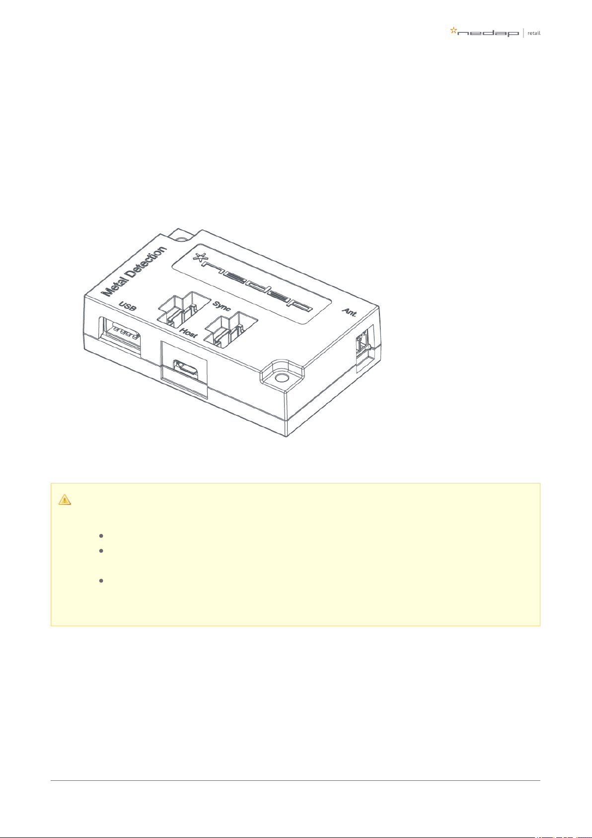
Metal Detection
The Renos Metal Detection unit (#9563717) can be used to detect foil-lined bags, which are sometimes used
by thieves to prevent the RF tags from being read by the detection system or reader. With metal detection, we
can detect metal objects and provide a discrete alarm to the store employees.
Restrictions for metal detection
You need a minimum of 2 gates with Metal Detection units to work.
Only possible when there are no moving doors with metal (i.e. an aluminum frame around the
door).
Please note that for the connection of the Metal Detection in the FC-line antenna a longer
connection cable is needed (800 mm / 2.6 ft).
RF security dashboard
The Renos platform has a built-in RF security dashboard. It can be enabled by entering a license key during the
configuration wizard. The customer can then visit the dashboard via the web browser. To make this work, the
Renos system should be either connected to the customer network, or a stand-alone set-up with a router
should be made.
Page of 11 43 Manual FC-line
Page 12

1.
2.
3 Preparing the installation
When preparing an installation with FC-line products, there are a few things that should be taken into account:
How many gates one needs to cover an entrance or door.
Where the gates will be placed in relation to the environment, for example to minimize interference
(RF).
It is preferred to install the FC-line gate on the floor mount column. This will up the performance of the
system and still gives a clean look in the store.
What cabling need to be applied (Cat 5E cable).
The maximum distance between antennas is 2200 mm / 7.2 ft (2000mm / 6.6 ft recommended).
Mounting distance from the ground must be 200 mm / 8".
For mounting on concrete and stone walls, chemical anchors are preferred
For mounting on steel frames, EPDM rivet blinds are necessary, which are included in the installation
set
Distance brackets (25 mm / 0.98") are provided in the installation set, when possible install the FC-line
products with these distance brackets. This will improve the performance of the system, especially
recommended for steel frames.
The firewall settings that need to be in place to enable Device Management
Defining the system
When the store owner requires gates to be placed at several locations, one needs to decide on how to
combine these gates into one or multiple systems. The following rules shall be taken into account:
Create as large systems as possible. To minimize interference between gates, the Renos platform has a
built-in synchronization mechanism. For this synchronization mechanism to work, the gates need to be
connected in one system.
However, the maximum cable length requirements needs to be satisfied. If it is not possible to put all
the gates in one system due to the maximum cable length requirements of 100 meters / 109 yd, you
can split the gates into two or more systems. In this case assign each system a different multi-system
during the RF configuration.channel
Page of 12 43 Manual FC-line
Page 13
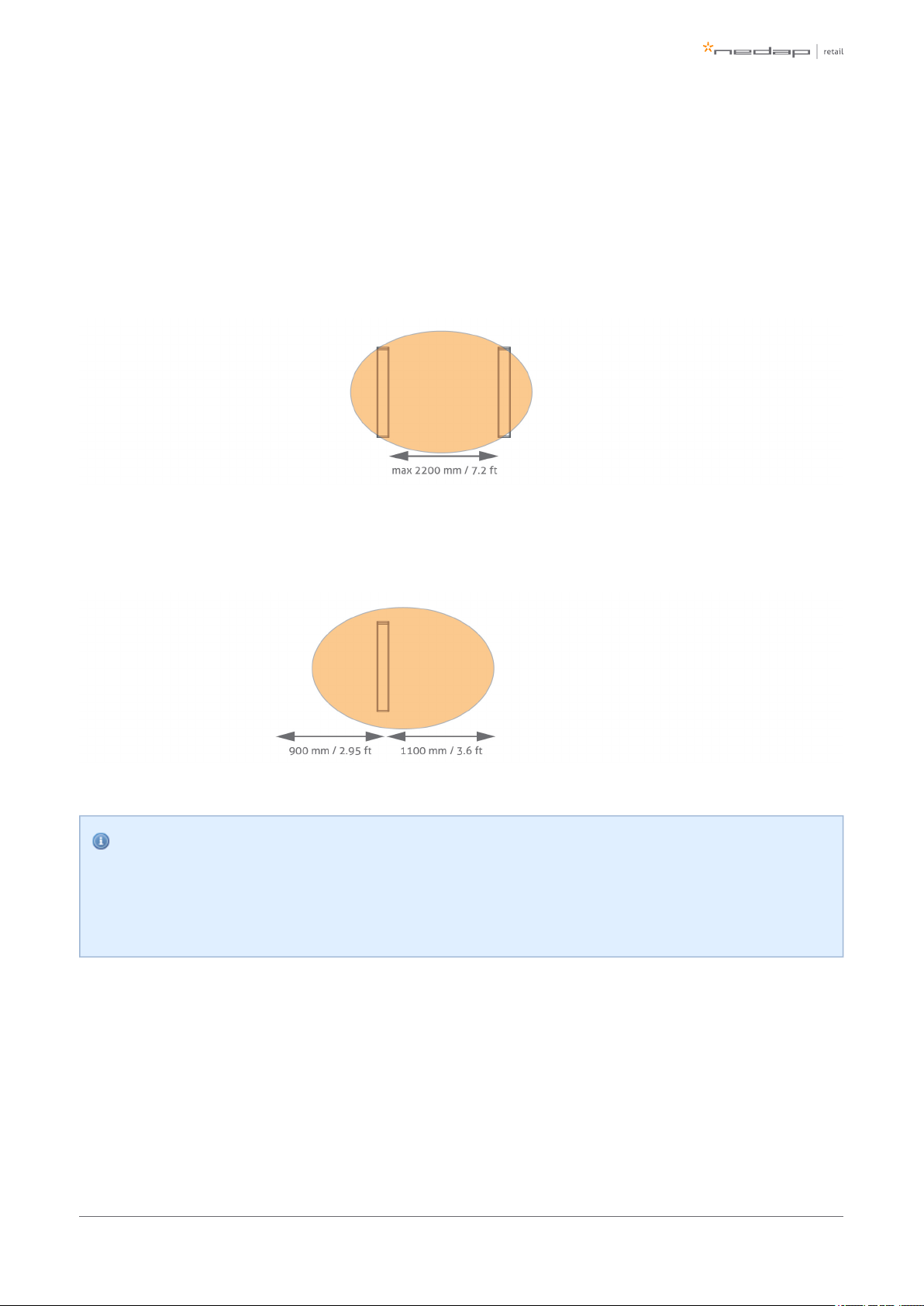
Field distribution for RF
There are two modes of operation for RF technology. The mode can be configured during the configuration
wizard.
There is an RF field in between gates. This mode is preferred for the best performance of theFocused field.
system.
There is an RF field around the gate. This mode is mainly used when the gates are placed near theFull field.
checkouts, as you can have one gate covering a relatively large area.
Infra-read beam sensors
Please note that when you want to use infrared beam sensors for customer counting, you can only
count customers in between the gates. So, if you set RF to full field, you are not able to count
customers outside of the gates.
Page of 13 43 Manual FC-line
Page 14

Device Management
All the Renos-based products can be connected to the Nedap Device Management Service. This service
provides:
Monitoring. Critical system parameters are monitored 24/7. As soon as something is wrong with the
system, an alert is generated to the supporting partner.
Remote log-in. Via the Device Management portal it is possible for an authorized Nedap-certified
engineer to access the user interface of the system to make changes to the configuration or access
system logs.
Remote Firmware update. It is possible to install new firmware releases remotely.
To use Device Management, please make sure that the following firewall ports are opened before installation:
TCP port 443 outgoing to *.nedapretail.com
This can be verified by connecting your laptop to the customer network, open your browser and navigate to
. You should see a special page there.https://api.nedapretail.com
It is also possible to do this via an HTTPS proxy, however, the remote log-in feature is not available then.
For more details, please see the Knowledge Base article on Device Management.
If Device Management is available at a certain site, it is possible to pre-configure a system, such that
the field engineer will have an easier job. For more information, please refer to the Knowledge Base
article on Pre-configuration.
Page of 14 43 Manual FC-line
Page 15

4 Executing the installation
When all the preparations are taken into account, the installation of the system can take place. The installation
consists of physically mounting the system in the right orientation, installing the cabling and applying power
to the system.
Physical installation: Wall mounting
The FC-line gates can be mounted in three different methods:
Mounted on the floor mount column (recommended)
Mounted on the front of the door frame
Mounted on the side of the door frame
Distance to the floor
The distance to the floor should be at least 200 mm / 8" to have enough space for cabling and filters.
Rotation of the antenna
The antenna can be rotated vertically to create the optimal focussed RF field. Please note that only
when both sensitive sides of the two antennas are facing each other, the maximum distance of 2200
mm / 7.2 ft can be obtained. When rotating the antenna, please make sure the Customer Counter
PCB's also face each other to work properly. The Customer Counter PCB can easily be rotated inside
the antenna.
Prevent interference
Using the floor mount column increases the performance of the FC-line gate. It prevents interference
from the door frame or wall behind the door frame. When mounting the FC-line gate to the door
frame, using the distance brackets included in the installation set, will help prevent interference.
Order floor mount column seperately
The floor mount column is not included in the product, but should be ordered separately, article
number 9216561.
Page of 15 43 Manual FC-line
Page 16

1.
2.
3.
4.
5.
6.
7.
8.
9.
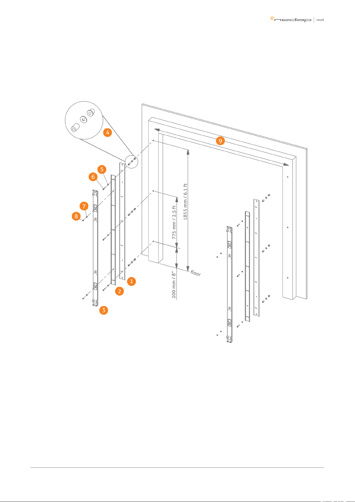
Mount on floor mount column
The next drawing specifies the mounting of the FC-line antenna on the floor mount column.
Place the floor mount column on the floor. Drill four holes to mount the column to the floor.
Mount the column to the floor using the isolation sleeve, washer, nut DIN 1587 and an M10 bolt
(included in the installation set).
EPDM rivet blind M8
Washer M8
Bolt M8
Washer M8
Nut M8
Mounting brackets are included in the box of the FC-line.
Distance between antennas 1800 mm / 5.9 ft - 2200 mm / 7.2 ft (2000mm / 6.6 ft recommended).
Page of 16 43 Manual FC-line
Page 17
1.
2.
3.
4.
5.
6.
7.
8.
9.
Mount on the front of the door frame
The drawing below specifies the mounting of the FC-line antenna on the front of the door frame using the wall
mount brackets included in the box.
Bracket RVS
Bracket 1 (included in the box)
Bracket 2 (included in the box)
EPDM rivet blind + Washer M8 DIN9021 + Distance bracket 25mm / 0.98"
Washer M8
Bolt M8
Washer M8
Nut M8
Distance between antennas 1800 mm / 5.9 ft - 2200 mm / 7.2 ft (2000mm / 6.6 ft recommended).
Page of 17 43 Manual FC-line
Page 18

1.
2.
3.
4.
5.
6.
7.
8.
9.
10.
Mount on the side of the door frame
The drawing below specifies the mounting of the FC-line antenna on the side of the door frame using the wall
mount bracket included in the box.
Bracket RVS
Bracket 1 (included in the box)
Bracket 2 (included in the box)
EPDM rivet blind + Washer M8 DIN9021 + Distance bracket 25mm / 0.98"
Washer M8
Bolt M8 x 50
Bolt M8 x 25
Washer M8
Nut M8
Distance between antennas 1800 mm / 5.9 ft - 2200 mm / 7.2 ft (2000mm / 6.6 ft recommended).
Page of 18 43 Manual FC-line
Page 19

1.
2.
3.
4.
5.
Physical installation: Mount electronic unit
The drawing below specifies the mounting of the electronic unit to the wall mount bracket or floor mount
column.
Bracket 1 + Bracket 2
Electronic unit
Nut M4 x 10
Inbus bit 3mm - 1/4"
Bit holder (not included)
Page of 19 43 Manual FC-line
Page 20

1.
2.
3.
Physical installation: Installing cabling and filters
During the preparation phase, the exact cabling required was already determined. Now these cables can be
placed.
All wiring should be done according to local regulations.
Model ASSY FL180R RF+MD antennas with internal Renos shall only be powered by the POE
Model PW-085C-1Y560HPOE provided by Nedap. There are four article numbers for the POE
model available, according to the country of origin. Each is packaged in a box with one of
these mains cord: EU, USA, China, UK and Swiss.
To disconnect the system from the mains, please remove the power cord either from the POE
unit or from the mains power socket.
When cables are installed, it is recommended to mark them with IN and OUT, or PREVIOUS and NEXT,
as this will allow you to distinguish them from each other.
Filters
Please note that filters should be placed around the cables to reduce interference with other systems. These
filters are delivered together with the system.
Filter should be placed at:
Every Power Inserter: around the Ethernet cable, both at the OUT and IN port.
Every Renos unit: around the Ethernet cable, both at the OUT and IN port.
Every 9 m / 30 ft. for longer Ethernet cables.
To save yourself a huge amount of frustration, please first place the filters attaching thebefore
connectors. The other way around is not possible. Many have tried before.
Page of 20 43 Manual FC-line
Page 21

1.
2.
3.
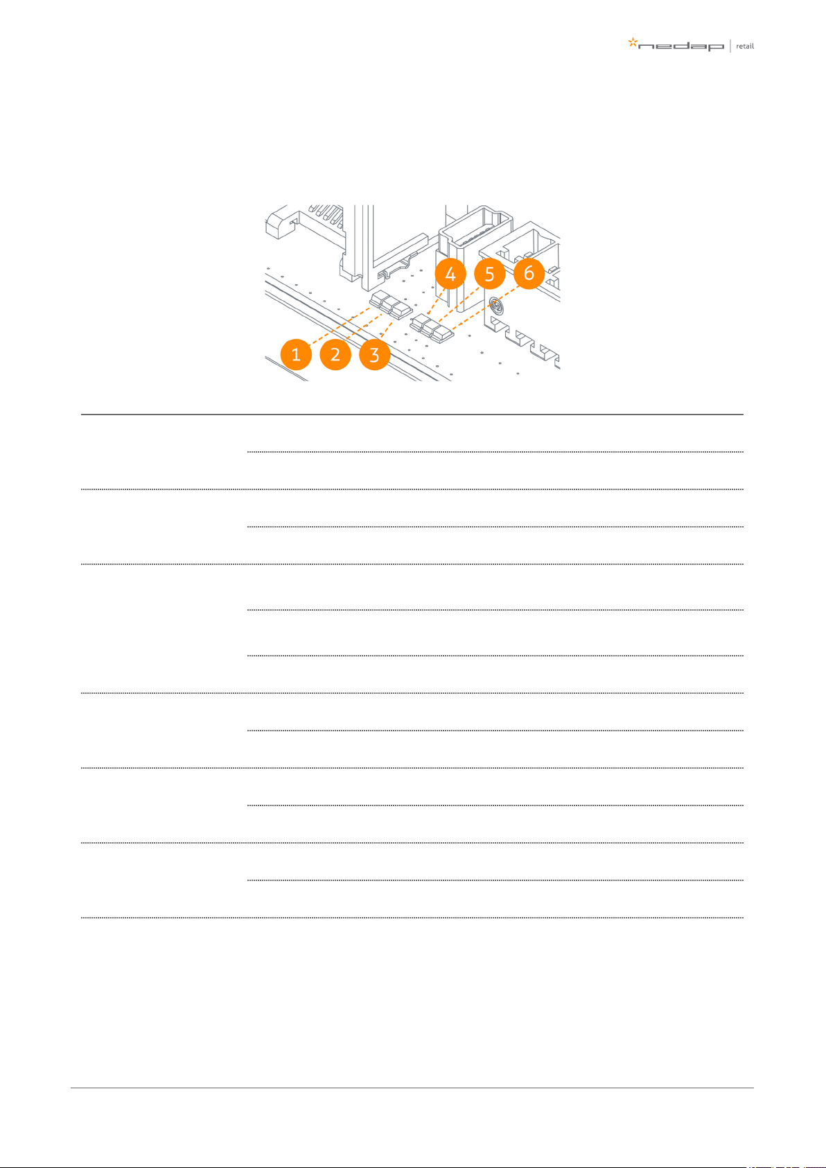
Power Inserter OUT to Renos IN
Renos OUT to the next Renos IN
Filters
Filters can be ordered as spare part with Nedap. Please refer to the Nedap Retail Portal for more
information.
Ethernet cables
Maximum length and type of Ethernet cable
The maximum data communication length for an Ethernet cable is 100 meter (328 ft.). Therefore we
recommend the following maximum distances:
The maximum cable length in between two Renos units is 100 meter (328 ft.) - even if there is
a Power Inserter in between.
The maximum cable length from the Power Inserter to the last Renos unit powered by that
Power Inserter is also 100 meter (328 ft.)
Please use Ethernet Cat. 5 cable or better and make sure to test every Ethernet cable for correct
connections and twisting of all 4 pairs (8 wires) with an Ethernet cable tester. This is to make sure
that the system can function correctly.
Page of 21 43 Manual FC-line
Page 22

1.
2.
Connect the Ethernet cable from the OUT port with the IN port of the next Renos unit
First, in all aisles connect the Ethernet OUT port with the IN port of the next Renos unit, always
following the directions of the arrows in the cabling indicated by the image above.
When the cable lengths allow for it, we recommend to place the Power Inserter in the switch room. In
this way the customer only has to arrange an Ethernet outlet near the installation, and no power
sockets are needed. This could reduce the cost for installations significantly.
When a connection to the customer network is to be made for local access or Device Management, this
connection can be made from:
The customer network to the IN port of the Power Inserter.
The customer network to the OUT port of the last Renos unit in the chain.
The exact location needs to be configured during the configuration wizard.
Page of 22 43 Manual FC-line
Page 23

1.
2.
3.
4.
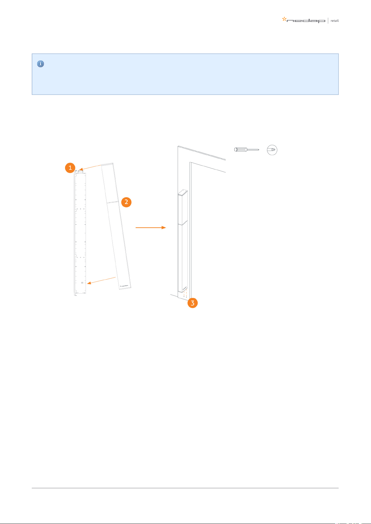
Physical installation: Mount the LED PCB
During transport the LED PCB is mounted in the transport position. During the installation the LED PCB must
be placed in the working position. See the drawing below for instructions.
Remove screw (2x)
Remove PCB from transport position
Place PCB to working position
Place screw (2x)
Page of 23 43 Manual FC-line
Page 24

1.
2.
3.
4.
Physical installation: Mount the Buzzer PCB
During transport the Buzzer PCB is mounted in the transport position. During the installation the Buzzer PCB
must be placed in the working position. See the drawing below for instructions.
Remove screw (2x)
Remove PCB from transport position
Place PCB to working position
Place screw (2x)
Page of 24 43 Manual FC-line
Page 25
1.
2.
3.
4.
5.
6.
7.
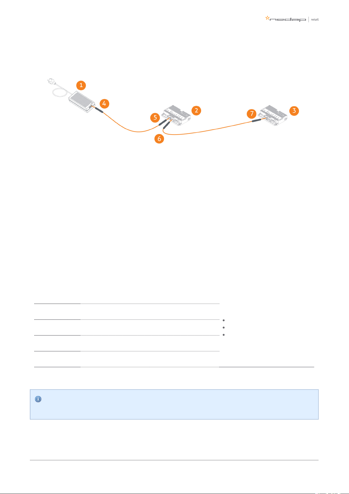
Connect Renos and Power Inserter
Power Inserter (not included, order separately)
ASSY FC180R RF
ASSY FC180R RF
Power Inserter - OUT
Renos - IN
Renos - OUT
Renos - IN
Power consumption Renos
When the installation location of the products is clear, the location of Power Inserters needs to be defined.
There is a maximum number of Renos units that can be connected to one Power Inserter, depending on which
technologies are used and the number of add-ons that are in use.
Technologies in
use
# units / Power Inserter 230V
# units / Power Inserter 115V
Index:
RF = Radio Frequency 8.2 MHz
MD = Metal Detection
2 SD's = 2 connected smart
deactivators
RF 6 5
RF + MD 4 4
RF + 2 SD's 5 4
RF + MD + 2 SD's 4 3
Please note that you can only use a Nedap Power Inserter (Power-over-Ethernet) to power Renos
systems. It is not possible to use generic Power-over-Ethernet switches or stand-alone inserters.
Page of 25 43 Manual FC-line
Page 26
Status LEDs on Renos unit
The electronics inside the unit has several status LEDs that can be used to discover the status of each part of
the electronics.
Led Color Status Explanation
1 Green
On There is a Renos unit connected to the OUT port of this unit
Off There is Renos unit connected to the OUT port of this unitno
2 Blue
Blinking There is device connected to the OUT port of this unitno
On There is a Power Inserter connected to the OUT port of this unit
3 Red
On
There is an issue with the power supply at the OUT port of this unit (too little
current drawn)
Blinking
There is an issue with the power supply at the OUT port of this unit (too much
current drawn)
Off There is issue with the power supply at the OUT port of this unitno
4 Yellow
Blinking The operating system on the Renos unit is running
Off The operating system on the Renos unit is runningnot
5 Green
Blinking The storage flash on the Renos unit is accessed
Off The storage flash on the Renos unit is accessednot
6 Green
On The firmware on the Renos unit is running
Off The firmware on the Renos unit is (yet) runningnot
Please refer to the Troubleshooting chapter later in this manual to resolve erroneous conditions.
Page of 26 43 Manual FC-line
Page 27
1.
2.
3.
If the Renos unit has a firmware error, the rightmost three LEDs (4, 5 and 6) will remain off when the
unit is powered. This can be solved by using a 'Local - single unit' firmware update, as is described
later on in this manual.
Place cover
Place the cover over the electronic unit as shown in the image below.
Place the M4 x 12 bolts (2x) at the top
Hang the cover as shown
Fix the cover from below using M4 x 16 bolts (2x)
Page of 27 43 Manual FC-line
Page 28

5 Configuring the installation
To complete the configuration, the following tools are required.
Mini-USB cable.
Laptop with installed driver (if necessary) and recent browser.
Driver installation
To configure a Renos-based system, sometimes a driver needs to be installed. Please check the table below
whether you need to install a driver, based on your operating system.
Operating system Driver
Windows XP, Vista or 7 Download from portal
Windows 8 No need to install driver
Mac OS X No need to install driver
Linux No need to install driver
Once you have installed the driver, check if it works by plugging-in a Renos unit.
Recent browser
To configure the system, an HTML5 compatible browser should be installed on your laptop. The following
browsers (or higher) are officially supported:
Google Chrome
Mozilla Firefox 6 (or higher)
Apple Safari 6 (or higher)
Microsoft Internet Explorer 9 (or higher)
If you don't have one of these browsers installed on your laptop, please install them now.
Page of 28 43 Manual FC-line
Page 29
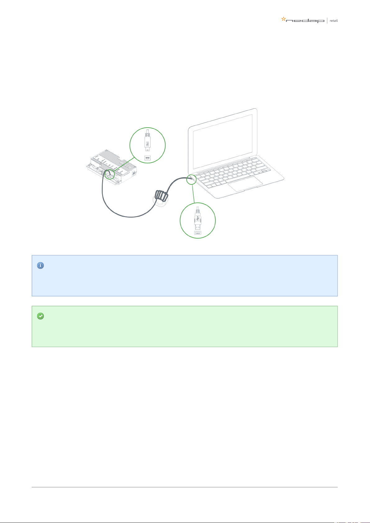
Connecting a laptop to the Renos unit
You can connect your laptop via a Mini-USB cable to the service port on the Renos unit. You can choose any
Renos unit in the system.
It is advisable to use a long USB cable. This is more comfortable as you can find a good place to put
your laptop (instead of on top of stairs, or on the floor next to the antenna). Besides, some laptops
cause interference on the RF technology, so it is better to place them further away.
We advise to use a ferrite ringcore filter around the mini USB cable that is used to configure Renos.
These can be ordered as spare part with Nedap. Please refer to the Nedap Retail Portal for more
information.
Entering the configuration wizard
You can enter the configuration wizard by opening your browser, and navigating to:
http://192.168.133.1
Authentication
During the configuration, the user is required to authenticate himself. How this is done, is dependent on the
Device Management availability.
Page of 29 43 Manual FC-line
Page 30

1.
2.
3.
4.
a.
b.
c.
5.
6.
7.
The system is connected to Device Management: you can directly enter your Nedap Retail username
and password.
The system is not connected to Device Management, and you don't have a Nedap Retail authentication
software: choose one of the following steps:
If your laptop is able to connect to Device Management via a 3G dongle or Wi-Fi, you can use
this option to enter your username and password.
If that is not available, you can use your smartphone.
If your smartphone has no internet access, you can call our support to get an authentication
code.
Please contact support for more details on how to obtain a Nedap Retail username and password.
Getting help in the wizard
If something is not clear, each page has a question mark button in the top right corner. You can click this to get
more information on what is expected to do on a certain page.
Firmware version and System ID
When you ask for support for a specific system, the support engineer will always ask you for the firmware
version and the system ID. The firmware version is displayed in the right top of the configuration wizard. If you
click the firmware version, a pop-up will appear that shows the System ID.
Factory reset
To execute a factory reset on a single Renos unit, the following steps need to be executed:
Turn off the system by removing the power cable of the Power Inserter.
Connect a Mini-USB cable from the USB service port to the USB port on the Renos unit.
Reconnect the power cable to the Power Inserter.
The LED that usually indicates that the firmware is running (the green LED on the right) will show the
following behavior:
Blink couple of times
Stay on
Blink couple of times
When this is completed, wait one minute before proceeding.
Turn off the power.
Remove the USB cable.
Turn on the power.
Page of 30 43 Manual FC-line
Page 31

1.
2.
3.
Configuration is lost
Please note that when doing a factory reset, all settings and configuration of the unit are lost. The
firmware version does not change.
Firmware change
There are three ways to change the firmware version on a Renos-based system:
Device Management update. The update can be executed via the Device Management service.
Local - single unit flash. The update can be executed by inserting a USB stick with the right firmware
into the USB port.
Local - complete system flash. The update can be executed during the configuration wizard with files
on your laptop.
If the system is integrated with a 3rd party system, please confirm the firmware version with that 3rd
party before installing it.
Device Management update
To update the firmware via Device Management, please make sure the system is configured, delivered and
connected to the Device Management service. Then, navigate to the Device Management website and use the
functionality there to initiate the firmware update.
Local - single unit flash
Download the correct firmware image file from the Nedap Retail portal. Extract this file to a USB stick. Turn off
the power of the system. Insert the USB stick in the USB port of a Renos unit. Power the system. Wait until
LEDs 4, 5 and 6 are off again. This can take around ten minutes. Then turn off the power again, remove the USB
stick and turn on the power.
Configuration is lost
Please note that when using 'local - single unit flash' firmware change, all settings and configuration
of the unit are lost.
It's only possible to execute this on-site and not remotely, as the system needs to be re-configured
before it is usable again.
Page of 31 43 Manual FC-line
Page 32

Local - complete system flash
Download the correct firmware image file from the Nedap Retail portal. Enter the configuration wizard and
accept all Renos units in the system that should be updated. Press the Advanced button and follow the steps
to change the firmware. One of these steps is to upload the firmware image file.
Configuration is lost
Please note that when using 'local - complete system flash' firmware change, all settings and
configuration of the system are lost.
It's only possible to execute this on-site and not remotely, as the system needs to be re-configured
before it is usable again.
Page of 32 43 Manual FC-line
Page 33

6 Integrating the installation with other
systems
It is highly recommended to integrate the FC-line product into other solutions in use at the end customer.
Software integration with API's
The Renos platform offers several API endpoints that deliver events. Those events include:
RF alarms
Infrared beam sensor events
For more information please refer to the Software integration page on the Nedap Retail Portal with
documentation and examples.
Physical integration using an IO Box
It is also possible to integrate other systems via relay contact outputs and inputs. This is not directly provided
by the Renos unit, but can be done via a 3rd party IO Box.
Supported 3rd party IO Box
At the moment, the following 3rd party IO Box is supported:
MOXA ioLogik E1214
The IO Box should be connected to a Renos unit via a USB to Ethernet adaptor.
An output on an IO Box can be switched when one of these events occur:
There is an RF alarm
Someone has pressed the attention button on the RF deactivator
The deactivator has deactivated a RF label
Activating an input on the IO Box can be used to control the system in the following way:
Disable RF transmitter
Page of 33 43 Manual FC-line
Page 34

URL trigger
Network-based devices that have an http-based-API can be triggered with the URL trigger mode. At this
moment cameras and Renos Pager are supported. A control URL (a link containing information) of thisAxis
device can be triggered by an RF alarm, Metal Detection alarm or an Attention Button alarm. The URL should
be created in the device. The communication can be further configured in the configuration wizard. Make sure
that this device is reachable by the Renos system.
Page of 34 43 Manual FC-line
Page 35

7 Servicing the installation
When the installation has been completed and delivered, it is possible to service the installation via Nedap
Device Management. Besides, we provide monitoring options locally via SNMP.
Nedap Device Management
Via Nedap Device Management the following features are available, when the system is connected to Nedap
Device Management.
System monitoring via some key metrics. The following key metrics are available:
Whether all Renos units are active
Whether all infrared beam sensors are operating without blocked aisles
Whether the buzzers and lights are muted
Firmware update. As described before, the firmware of the Renos system can be updated via Device
Management.
Remote log-in. It is possible to access the configuration wizard remotely via Device Management.
These features are available via a web interface and an API, which can be used to integrate Nedap Device
Management into 3rd party solutions. For more information, please contact support.
SNMP
To allow for local monitoring of Renos systems, and integration into existing IT infrastructure we support
Simple Network Management Protocol (SNMP). The following variables are available on the Renos platform:
One or more Renos units are not reachable
One or more infrared beam sensors are blocked
The system is connected to Device Management
Renos systems use SNMP version 2c, community public. The MIB file is available on the Renos system itself via
the URL http:// /snmp (for example, that is when(ip address of the system) http://192.168.133.1/snmp
connected to the USB service port).
Page of 35 43 Manual FC-line
Page 36

8 Troubleshooting
If the system is not working correctly, please check the troubleshooting options below. If it is not possible to
solve your issue, you can find support options in the next chapter.
Physical installation
Symptom Cause Solution
The red LED (3) on a
Renos unit is on.
The current drawn out of the OUT port of the Renos unit
is too low. The cabling at the OUT port of the Renos unit
does not satisfy the maximum length requirements.
Verify whether the cabling length in the
system satisfies the requirements posed
earlier in this document.
The current drawn out of the OUT port of the Renos unit
is too low. The connectors of the Ethernet cable at the
OUT port of the Renos unit are not mated properly.
Check the Ethernet cabling at the OUT
port of the Renos unit with a Ethernet
cable tester.
The red LED (3) on a
Renos unit is blinking.
The current drawn out of the OUT port of the Renos unit
is too high. Too much Renos unit and add-ons connected
to one Power Inserter.
Verify the number of Renos units and
add-ons connected to the Power
Inserters with the table earlier in this
document.
The current drawn out of the OUT port of the Renos unit
is too high. There is a short circuit in the cabling leaving
the OUT port of this Renos unit.
Check the Ethernet cabling at the OUT
port of the Renos unit with an Ethernet
cable tester.
The green LED (1) on a
Renos unit is off, but
there is a unit behind
this unit.
There is an issue in the cabling between those unit, such
that the following unit is not recognized.
Check Ethernet cabling with an Ethernet
cable tester.
Page of 36 43 Manual FC-line
Page 37

1.
2.
a.
Configuration
Symptom Cause Solution
It is not possible to access the
configuration web interface.
Renos unit has not started yet
Verify the green "firmware running" LED on
the Renos unit (6). If this LED is not on,
verify the system has power or wait five
minutes and try again.
Mini USB cable not attached to Renos unit and
laptop
Attach cable to Renos unit and laptop.
Driver not installed
On Windows 7 and older you manually need
to install a driver to support Renos.
I have put a system together,
but I only see a part of all units
during the hardware
discovery.
During configuration, the WAN access port will
be ‘closed’ for internal network traffic. If you
combine two systems later on, this needs to
be re-openend.
Do a factory reset on the unit that was
previously used as WAN entry point.
If that doesn't work, do a factory reset on all
units.
There is a cabling error.
Please check all Ethernet cabling with an
Ethernet cable tester.
Not all Power Inserters are powered, or some
Renos units are not fully started.
Verify the green "firmware running" LED on
the Renos unit (6). If this LED is not on,
verify the system has power or wait five
minutes and try again.
There is a firmware failure,
indicated by the fact that all
three LEDs 4, 5 and 6 are off
on the Renos unit.
Something might has gone wrong with a
firmware update.
Use the 'local - single' unit firmware update
mechanism to restore the unit.
RF technology issues
When there are issues with RF technology during the configuration (the gates show as orange or red in the
wizard), please follow the following steps:
Check the parameters in the RF Advanced Config of the configuration wizard, RF gate performance
section. Probably one of those parameters is red or orange.
Disable all transmitters.
If all parameters in the RF gate performance section turn green again, there is a coupling
problem (the transmitter couples with a label-like object in environment). Please continue at the
'coupling problem' section.
Page of 37 43 Manual FC-line
Page 38

2.
b. If all parameters in the RF gate performance section remain orange or red, there is an active
interferer (another device that transmit radio waves around the 8.2 MHz RF spectrum, like
another EAS system, an engine or a power supply). Please continue at the 'active interferer'
section.
Coupling problem
Coupling problems are caused by objects that act as a label to the RF system. For example metallic
doorframes, metal checkouts, cabling: everything that runs in a loop and is metallic.
To solve these problems, there are a few things you can try:
Tighten screws in the metallic construction. This might work for checkouts or customer guidance rails.
Try to interrupt the metallic loop. This can be done by using non-metallic parts inside those loops, or to
make a cut in them.
Create a shortcut in the metallic loop, to make it smaller. In this way it will resonate at a different
frequency.
If the above solutions don't solve the problem, you can decrease the sensitivity of the system. This can be
done by ticking the 'reduced sensitivity' button in the RF Advanced Config.
If a decreased sensitivity doesn't work, and there is only one type of label or tag in the store, you
also have the option to increase the 'receiver delay', in steps of 3 dB.
If these things don't solve the problem, please contact support.
Active interferer
The first step is to try to locate the source of the active interferer. You can do this by unplugging electronic
devices around the gate (or move them away), and see if the parameters in the 'RF gate performance' section
improve, or when the average height of the spectrum is reduced. If this is the case, you have identified the
active interferer.
When the active interferer is known, the following solutions are possible:
Try to move the active interferer away from the gate as far as possible.
Try to apply filters around the cabling of the active interferer.
Shield the active interferer with aluminum foil of at least 0.05 mm (2 mil.).
If the above solutions don't solve the problem, you can decrease the sensitivity of the system. This can be
done by ticking the 'reduced sensitivity' button in the RF Advanced Config.
Page of 38 43 Manual FC-line
Page 39

There are also standard click-on ferrites available that can be used to reduce active interference
sources (e.g. Würth 742 711 31)
If these things don't solve the problem, please contact support.
Page of 39 43 Manual FC-line
Page 40

9 Regulatory information
FCC and IC Compliance statement
This device complies with part 15 of the FCC Rules and to RSS210 of Industry Canada. Operation is subject to
the following two conditions:
(1) this device may not cause harmful interference, and
(2) this device must accept any interference received, including interference that may cause undesired
operation.
Changes or modifications not expressly approved by the party responsible for compliance could void the
user’s authority to operate the equipment.
Cet appareil se conforme aux normes CNR210 exemptés de license du Industry Canada. L’opération est
soumis aux deux conditions suivantes:
(1) cet appareil ne doit causer aucune interférence, et
(2) cet appareil doit accepter n’importe quelle interférence, y inclus interférence qui peut causer une
opération non pas voulu de cet appareil.
Les changements ou modifications n’ayant pas été expressément approuvés par la partie responsable de la
conformité peuvent faire perdre à l’utilisateur l’autorisation de faire fonctionner le matériel.
FCC and IC Radiation Exposure Statement
This equipment complies with FCC and Canadian radiation exposure limits set forth for an uncontrolled
environment. This equipment should be installed and operated with a minimum distance of 20 cm between
the radiator and your body. This transmitter must not be co-located or operating in conjunction with any other
antenna or transmitter.
Cet équipement est conforme a CNR102 limites énoncées pour un environne- ment non contrôlé. Cet
équipement doit être installé et utilisé avec une distance minimale de 20 cm entre le radiateur et votre corps.
This Class B digital apparatus complies with Canadian ICES-3. Cet appareil numérique de Classe B est
conforme à la norme Canadienne NMB-3.
FCC Information to the user
Note: This equipment has been tested and found to comply with the limits for a class B digital devices,
pursuant to part 15 of the FCC Rules. These limits are designed to provide reasonable protection against
Page of 40 43 Manual FC-line
Page 41

harmful interference in a residential installation. This equipment generates, uses and can radiate radio
frequent energy and, if not installed and used in accordance with the instructions, may cause harmful
interference to radio communications.
However, there is no guarantee that interference will not occur in a particular installation. If this equipment
does not cause harmful interference to radio or television reception, which can be determine by turning the
equipment off and on, the user is encouraged to try to correct the interference by one or more of the
following measures:
Reorient or relocate the receiving antenna.
Increase the separation between the equipment and receiver.
Connect the equipment into an outlet on a circuit different from that to which the receiver.
Any changes or modifications not expressly approved by the party responsible for compliance could
void the user's authority to operate the equipment. To ensure compliance with FCC regulations, use
only the shielded interface cables provided with the product, or additional specified components or
accessories that can be used with the installation of the product.
Information for Taiwan
第十二條 經型式認證合格之低功率射頻電機,非經許可,
公司、商號或使用者均不得擅自變更頻率、加大功率或變更原設計之特性及功能。
第十四條 低功率射頻電機之使用不得影響飛航安全及干擾合法通信;
經發現有干擾現象時,應立即停用,並改善至無干擾時方得繼續使用。
前項合法通信,指依電信法規定作業之無線電通信。
低功率射頻電機須忍受合法通信或工業、科學及醫療用電波輻射性電機設備之干擾。
Page of 41 43 Manual FC-line
Page 42

10 About Nedap
About
At Nedap Retail, we work around the globe to deliver industry-leading products, services and solutions for our
customers’ diverse needs in loss prevention, stock management and store monitoring. Our inventive thinking
and collaborative spirit allows us to deliver tailor-made solutions for the fast paced retail sector.
We simplify retail management while improving your customers’ shopping experience. By taking most
recurring tasks off your hands, we create time for you to devote to your customers. And that is what retail is all
about. Whether you run a small local store or a large international chain, you will benefit from our broad range
of products, ideas and services. Nedap solutions are built upon 40 years of global experience, market
expertise and close cooperation with leading retailers. Our worldwide operations are supported by a flexible
network of certified partners across the globe. Nedap systems are future-proof (RFID-ready), cost-efficient and
eco-friendly. Our mission is simply to make sure your customers maintain the best shopping experience whilst
we help you protect your profits. Our philosophy: "your store - our store."
Contact
If you need any further details or require help in preparing an installation, executing an installation or
servicing an installation you are always welcome to contact our support team at: .support-retail@nedap.com
Suggestions for improving our products and documentation are of course always welcome.
Page of 42 43 Manual FC-line
Page 43

Last modification: 07 September 2015 09:11
N.V. Nederlandsche Apparatenfabriek 'Nedap'
Parallelweg 2d
NL-7141 DC Groenlo
the Netherlands
Page of 43 43 Manual FC-line
 Loading...