

Page 1
2011-12-06 Doc.no. 5279330
This information is furnished for guidance, and with no guarantee as to its accuracy or completeness; its publication conveys
no license under any patent or other right, nor does the publisher assume liability for any consequence of its use; specifications and availability of goods mentioned in it are subject to change without notice; it is not to be reproduced in any way, in
whole or in part, without the written consent of the publisher.
© Nedap AVI, P.O. Box 103, NL-7140 AC GROENLO Page 1 of 27
ANPR
Installation Guide
Page 2

ANPR
© Nedap AVI, P.O. Box 103, NL-7140 AC GROENLO Page 2 of 27
CONTENTS
1 INTRODUCTION ....................................................................................................................................................................................... 3
1.1
TYPICAL APPLICATIONS ............................................................................................................................................................. 3
1.2
KEY FEATURES ............................................................................................................................................................................... 3
1.3
DOCUMENT REVISIONS .............................................................................................................................................................. 3
2
GETTING STARTED .................................................................................................................................................................................. 4
2.1
MOUNTING THE ANPR ................................................................................................................................................................ 4
2.2
CONNECTING THE ANPR ........................................................................................................................................................... 4
2.3
ASSIGNING AN IP-ADDRESS ..................................................................................................................................................... 4
2.4
TESTING THE ANPR ...................................................................................................................................................................... 4
3
INSTALLATION ......................................................................................................................................................................................... 5
3.1
SAFETY PRECAUTIONS ............................................................................................................................................................... 5
3.2
MOUNTING ..................................................................................................................................................................................... 5
3.3
DIMENSIONS .................................................................................................................................................................................. 6
4
CONNECTIONS ......................................................................................................................................................................................... 8
4.1
ETHERNET CONNECTION ........................................................................................................................................................... 8
4.2
POWER SUPPLY ............................................................................................................................................................................. 8
4.3
RS485 CONNECTION ................................................................................................................................................................... 8
4.4
DIGITAL I/O ..................................................................................................................................................................................... 8
5
CONFIGURATION .................................................................................................................................................................................... 9
5.1
USING THE WEB SERVER ............................................................................................................................................................ 9
5.2
NUMBER PLATE READER CONFIGURATION .................................................................................................................... 10
5.2.1
GENERAL ......................................................................................................................................................................... 10
5.2.2
CAMERA OCR ................................................................................................................................................................ 11
5.2.3
PLATE READER .............................................................................................................................................................. 12
5.2.4
DIGITAL TRIGGER ......................................................................................................................................................... 14
5.2.5
CHECK LIST ..................................................................................................................................................................... 15
5.2.6
EVENTS / ACTIONS ...................................................................................................................................................... 16
5.2.7
IMAGE RESULT .............................................................................................................................................................. 21
5.2.8
TEXT RESULT .................................................................................................................................................................. 21
5.2.9
STATISTICS ..................................................................................................................................................................... 21
5.3
SYSTEM CONFIGURATION ..................................................................................................................................................... 22
5.3.1
NETWORK ....................................................................................................................................................................... 22
5.3.2
HTTP USERS ................................................................................................................................................................... 22
5.3.3
RS485 SERIAL PORT .................................................................................................................................................... 23
5.3.4
FIRMWARE ...................................................................................................................................................................... 23
5.3.5
DEVICE INFO .................................................................................................................................................................. 24
5.3.6
DIGITAL I/O .................................................................................................................................................................... 24
5.3.7
SYS STATISTICS ............................................................................................................................................................. 25
5.3.8
SECURE DIGITAL ........................................................................................................................................................... 25
A
COUNTRY CODES ................................................................................................................................................................................. 26
B
TCP TAG IDENTIFIER OVERVIEW ..................................................................................................................................................... 27
Page 3

ANPR
© Nedap AVI, P.O. Box 103, NL-7140 AC GROENLO Page 3 of 27
1 INTRODUCTION
The NEDAP ANPR License Plate Reader offers automatic number plate reading. The NEDAP ANPR is an all in one
camera including camera, analyzer and IR illuminator. The ANPR has embedded processing software onboard.
The License Plate Reader is default featured with an RS485 and Ethernet communication. Wiegand is possible
using the separate available Wiegand Interface Module.
1.1 TYPICAL APPLICATIONS
Typical applications include parking, crime prevention, toll systems, security and access control, logistics and
customs. In addition the NEDAP ANPR can be applied in applications where it is difficult to issue RFID tags.
1.2 KEY FEATURES
• Automatic number plate reading.
• All-in-one system including camera, analyzer, IR illuminator.
• Optimal performance in range from 3 to 6 meters.
• Library installed supporting all European countries (libraries for world-wide support available).
• Easy user configuration (web server).
• TCP/IP Ethernet interface.
• RS485 serial interface.
• Optical isolated digital input to trigger image captu r ing.
• Stand-alone operation supported by digital output and black-, and white-list features.
• 4GB SD-card memory to store log files and/or captured images.
• Wiegand Interface Module available for seamless integration with access control systems.
1.3 DOCUMENT REVISIONS
Version Date Comment
0.4 2011-12-06 RS485 A/B naming corrected
0.3 2011-11-10 Text corrections
0.2 2011-10-25 Update introduction and getting started chapters
0.1 2011-07-12 Initial document version
Page 4

ANPR
© Nedap AVI, P.O. Box 103, NL-7140 AC GROENLO Page 4 of 27
2 GETTING STARTED
2.1 MOUNTING THE ANPR
Determine how to mount the ANPR. Onto a pole or behind the barrier. Mount behind the barrier to ensure
recognition right in fron t o f the barrier.
Important mounting issues are:
• Best focus distance is between 3 and 6 meters.
• Angle between ANPR and number plate should be smaller than 25 degrees.
Mounting details are described in chapter 3.
2.2 CONNECTING THE ANPR
The ANPR is delivered with 5m cables for power, I/O and network. Power supply, RS485 communication and I/O
are combined in one cable. Ethernet network is a second cable. The cables are pre-fitted to the ANPR. For
installation the ANPR does not need to be opened.
Connecting the power supply and network cables are required to configure the ANPR.
Connection details are described in chapter 4.
2.3 ASSIGNING AN IP-ADDRESS
Enter the default IP-address in the address bar of your web browser.
Default IP address is:
IP address: 192.168.0.21
The login window appears where the user is asked to type the username and password.
Username: superuser
Password: superuser
Go to the system configuration and setup the network configuration as desired. If required, now also other
configuration settings ma y b e changed.
Details about network settings are described in chapter 5.3.1.
2.4 TESTING THE ANPR
Test the ANPR to check if it is aligned correctly and if it is able to read the license plates.
Drive the vehicle into the position where it should be possible to read its license plate.
Connect to the ANPR using your web browser and select the 'Camera OCR' feature. On the left side of the page
'live' video images are shown and also the license plate reading results. It might be necessary to adjust the ANPR
alignment.
Page 5
ANPR
© Nedap AVI, P.O. Box 103, NL-7140 AC GROENLO Page 5 of 27
3 INSTALLATION
3.1 SAFETY PRECAUTIONS
The following safety precautions must be observed during normal use, service and repair.
• The ANPR shall be connected to safety ground.
• Disconnect the power supply before removing any parts.
• The ANPR shall only be installed and serviced by qualified and trained personnel.
• To be sure of safety, do not modify or add anything other then mentioned in this manual or indicated by
NEDAP N.V.
• CAUTION: for continued protection against risk of fire, replace fuses only with the same type and rating.
• The ANPR can be powered from a low power, Class 2 power supply, in compliance with local regulations.
• The ANPR is equipped with an 850nm Infrared illuminator. The human eye will not or slightly see this light
coming from the illuminator. Do not look into the ANPR lens directly from close range or for more than 100
seconds. Eyes can be damaged by not taking these precautions. During normal use of the ANPR at a vehicle
gate, reading plates, there is no risk to the public.
3.2 MOUNTING
The ANPR is intended for vehicle access control. Vehicles are identified by the number plate when approaching
the gate. Because the number plate recognition is very fast, a full stop is normally not necessary. The ANPR
covers a reading distance of 3 to 6 meters. The field of view is typically one lane wide. There are 2 recommended
positions for the ANPR.
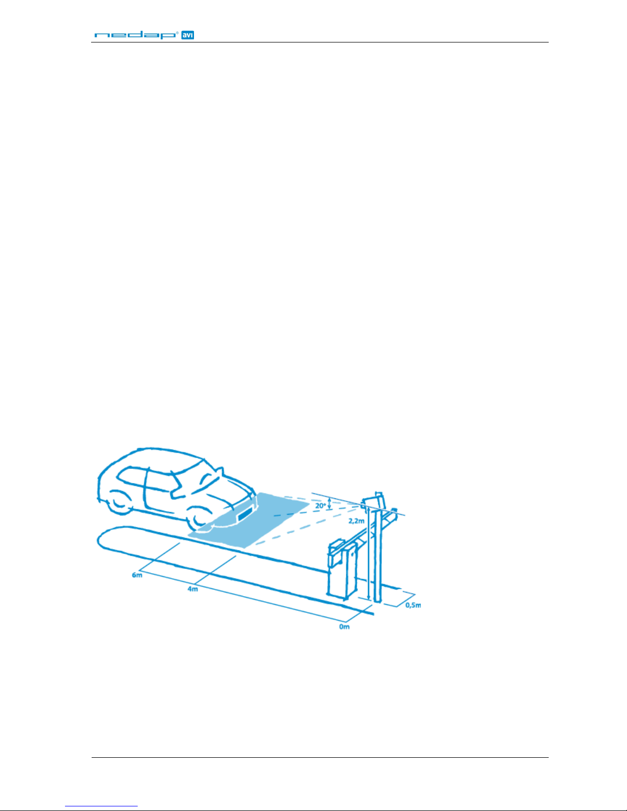
Pole mounting
The ANPR is positioned directly behind or in front of the actual barrier onto a pole. In that case the ANPR can be
best positioned on a pole at maximum 2m20 height. In this position the number plate of the vehicle directly in
front of the barrier cannot be read anymore. So these vehicles need to be recognized in flow. Mounting the
ANPR at 2m20 height is here the best option. When overhead installation is an option, the ANPR can at best be
installed in the center of the lane, above the lane. Horizontal angle will be 0° in that case, which is good.
Figure 1: Pole mounting
Page 6
ANPR
© Nedap AVI, P.O. Box 103, NL-7140 AC GROENLO Page 6 of 27
Behind barrier mounting
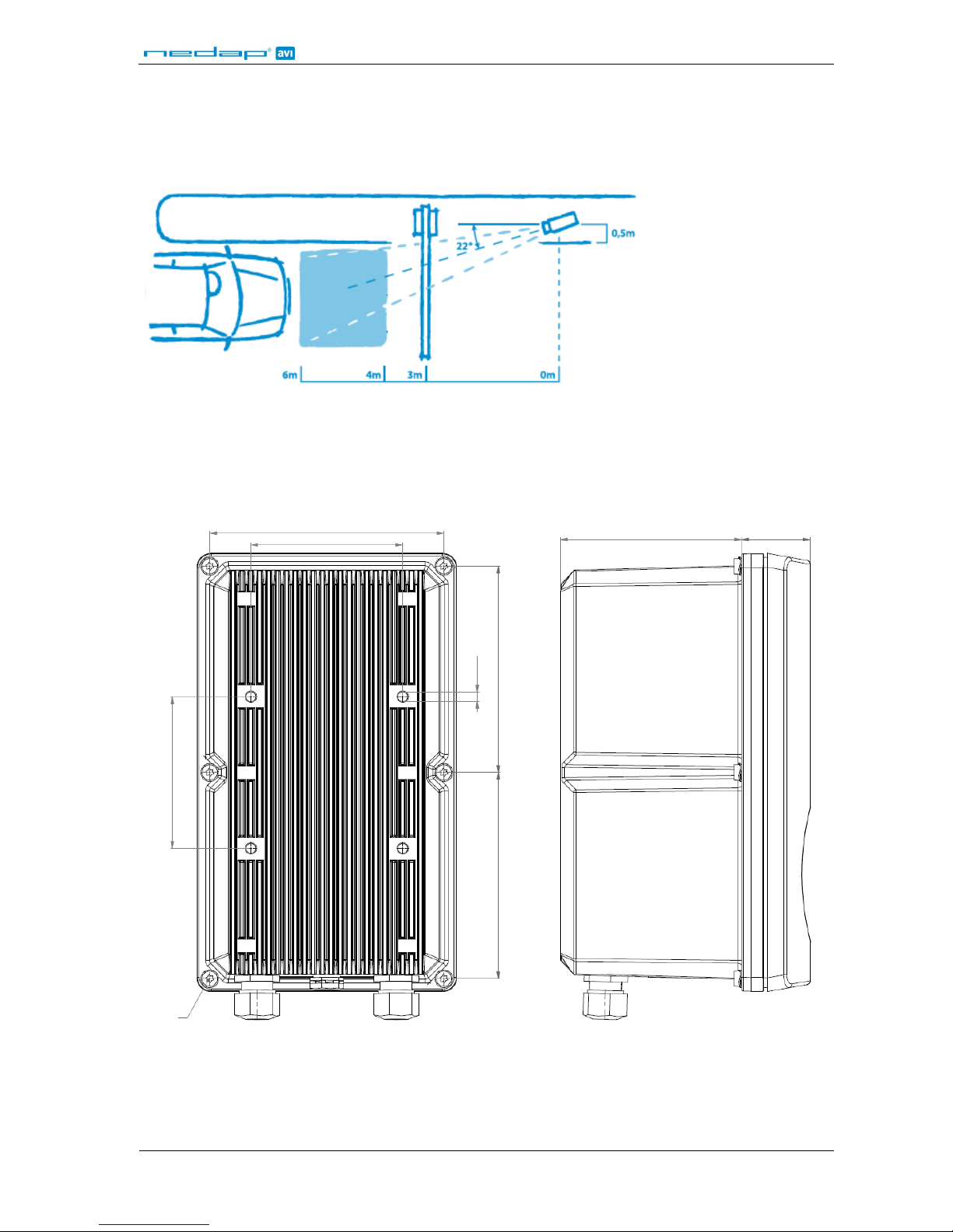
The ANPR is positioned behind the barrier at bumper height.
If there is space behind the barrier and the sight is not blocked, then the best place for the ANPR is at bumper
height (0.5m height) about 2 to 3 meters behind the barrier. A vehicle just in front of the barrier is still recognized
in that case.
Figure 2: Behind the barrier mounting
3.3 DIMENSIONS
Figure 3: ANPR housing dimensions
118
76.5
91
35
104 104
M6 (4x)
76.5
M4x12 (6x)
Page 7
ANPR
© Nedap AVI, P.O. Box 103, NL-7140 AC GROENLO Page 7 of 27
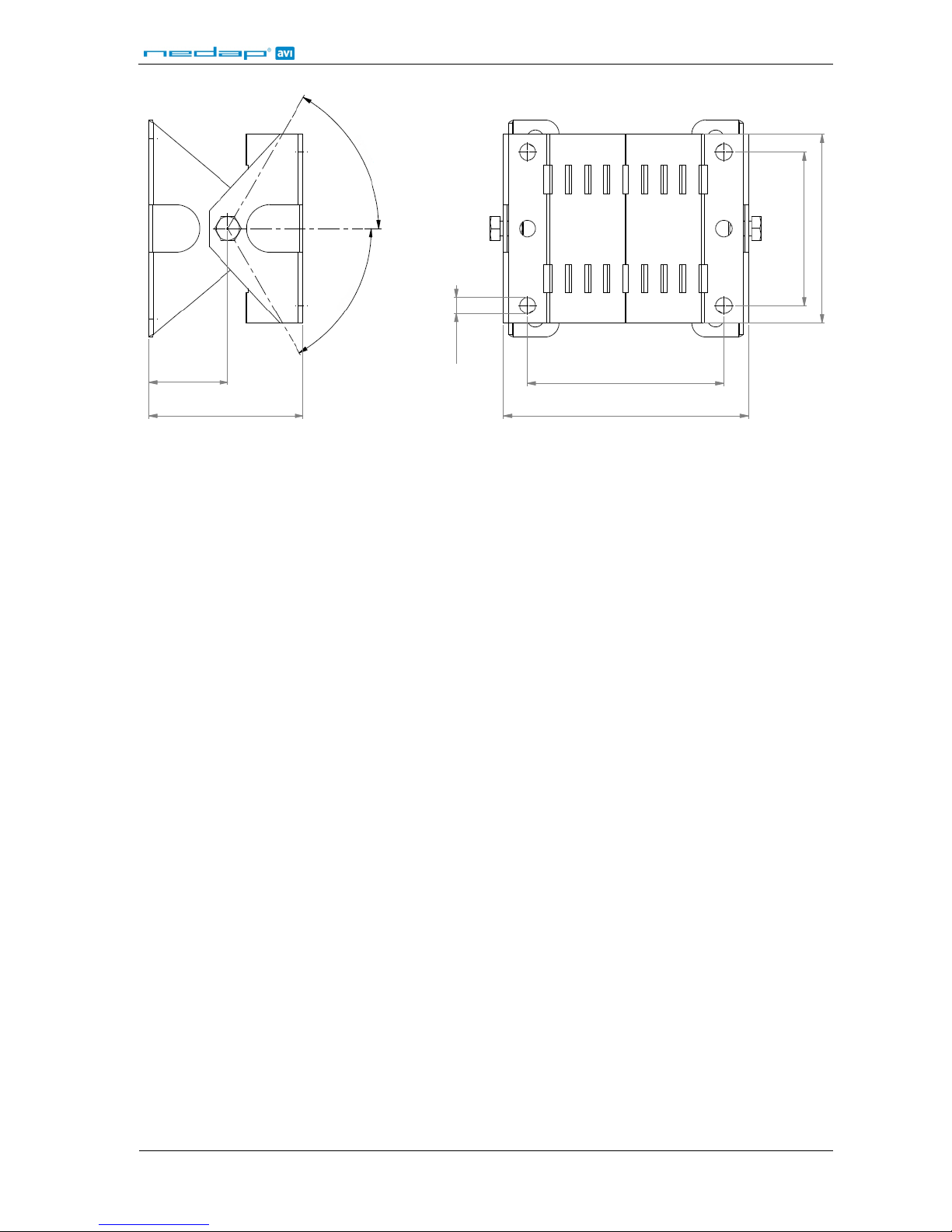
Figure 4: Mounting bracket dimensions
104
83
66
34
Ø7 (4x)
65
80
60° max
60° max
Page 8

ANPR
© Nedap AVI, P.O. Box 103, NL-7140 AC GROENLO Page 8 of 27
4 CONNECTIONS
The ANPR is delivered with two 5m long cables. Power supply, RS485 communication and I/O are combined in
one cable. Ethernet network is a second cable. The cables are pre-fitted to the ANPR. For installation the ANPR
does not need to be opened.
4.1 ETHERNET CONNECTION
The Ethernet cable is already fitted to the ANPR provided an RJ-45 connector. This Cat5e cable will be adequate
for connection of the unit to a local area network.
4.2 POWER SUPPLY
RED Power supply +24VDC.
BLUE Ground 0V.
4.3 RS485 CONNECTION
YELLOW RS-485 A
GREEN RS-485 B
PURPLE RS-485 GND / SC (voltage reference)
4.4 DIGITAL I/O
GRAY Digital input IN+ (optocoupler positive c ontact, U
max
PINK Digital input IN– (optocoupler negative contact).
= 24VDC).
BROWN Relay output (normally open contact, U
max
= 24VDC, I
max
WHITE Relay output (common contact).
= 2A).
Page 9
ANPR
© Nedap AVI, P.O. Box 103, NL-7140 AC GROENLO Page 9 of 27
5 CONFIGURATION
5.1 USING THE WEB SERVER
Prior to accessing the ANPR using a Browser, make sure the PC network configuration is coherent with the IPaddress of the device to access. E.g.: if the ANPR IP-address is 192.168.0.21, the PC in use should have assigned
an IP-address belonging to the same class (e.g. 192.168.0.22). See also chapter 2.3 for details about how to assign
an IP-address to the ANPR.
Figure 5: Using the web server
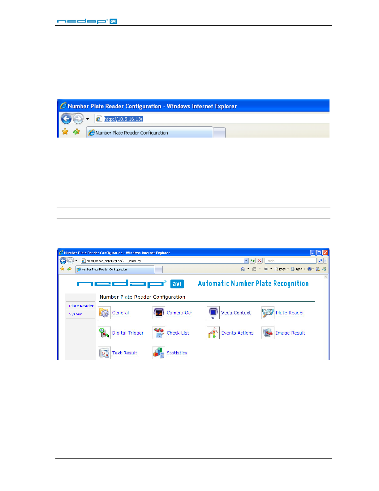
Enter the IP-address (or NetBiosName) in the address bar of your web browser.
The login window appears where the user is asked to type the username and password.
Factory default username and password are:
Username: superuser
Password: superuser
Note: It is recommended, to change the factory default username and password after installation. See chapter 5.3.2.
If the login was successful, the user is now able to access the main menu screen. The main page shows two
sections: Plate Reader and System. Refer to chapters 5.2 and 5.3 for further details.
Figure 6: Web server main menu
Page 10

ANPR
© Nedap AVI, P.O. Box 103, NL-7140 AC GROENLO Page 10 of 27
5.2 NUMBER PLATE READER CONFIGURATION
5.2.1 GENERAL
The ANPR system can operate in three different modes:
• FREE RUN mode
• TRIGGER by digital input mode (see chapter 5.2.4 about how to setu p th e digital input to trigger the ANPR).
• TRIGGER by ethernet mode (see the ANPR ethernet programmers guide about how to trigger the ANPR by
ethernet).
When in FREE RUN mode, the ANPR freely grabs and processes images. The software automatically detects the
presence of a number plate in the image and thus generates events.
When in TRIGGER-START-STOP mode, the ANPR grabs and processes the images in the time period between the
start trigger and the stop trigger. I n case the sto p trigger is n ot being a ctivated within the G ateTim eMax interval,
the system automatically generates the stop trigger after the interval expires. Any stop trigger received prior to a
start trigger will be ignored. Any start trigger received after a start trigger immediately generates an event and
restarts the image p rocessing.
When in TRIGGER-START-TIME mode, the un it starts image grabbin g whe n the star t trigger is activated and stops
image grabbing after a time in terval tha t was previo usly d efined in the GateTimeMax setting (see chapter 5.2.4).
Once GateTimeMax has expired, an event is generated. If the system receives a start trigger during GateTime
period, it immediately generates an event and restarts the ima ge processing.
When in TRIGGER-START-FREE-RUN-STOP mode, the unit starts image grabbing when the start trigger is
activated and then starts grabbing and reading number plates in FREE RUN mode. The system may generate
multiple events during the interval between start trigger and stop trigger.
When in TRIGGER by ethernet mode the image grabbing and processing is started upon receiving the start
TRIGGER message from the Ethernet network. The start trigger message contains a precise time in milliseconds
that expresses the GateTime during which the ANPR will grab images. When GateTime expires or upon receiving
a stop trigger message , the machine stops image grabbing. The trigger message also contains a gene ric string
the system uses to generate trigger messages where info may be inserted. Such string will later made available
on the web interface using the %NET_TRIG_ID tag. This makes it possible to associate to any event data, images
and other info about the specific trigger message from which they were originated.
The system may generate the following events upon a processed image:
• OCR READ
• OCR NOT READ
• OCR NO PLATE (not in FREE RUN mode)
The General Settings page contains the following configuration fields:
Enable Engine: It allows enabling/disabling the processing of the images grabbed by ANPR. The
parameter takes two possible values: YES or NO. If set to NO, the device is switched to
stand-by mode and its infrared illuminator is disabled. It will ignore any external
trigger. The infrared illuminator is only momentarily enabled if the Camera OCR page
is being accessed.
Acquisition mode: It allows selecting the system operating mode. Select FREE-RUN, TRIGGER-START-
STOP, TRIGGER-START-TIME, TRIGGER-START-FREE-RUN-STOP or TRIG GER-ETHERNET.
Site Address: This field can contain an alphanumeric string, such as the address of a system
location. This string is available as %SITE_ADDRESS TAG and can be sued in the text
value field of the Save Image action.
TCP message after ftp actions: With this parameter you can enable sending a TCP message after ftp actions
(ftp save image and ftp save DB).
Page 11

ANPR
© Nedap AVI, P.O. Box 103, NL-7140 AC GROENLO Page 11 of 27
5.2.2 CAMERA OCR
This page configures the Frame Grabber Settings.
On the left side of the page 'live' video images are shown. The red rectangle on the image border represents the
search plate window. It is possible to set size and position of this window in Plate Reader page.
General
Grab Mode: Here it is possible to set the image grabbing mode and camera related settings. Three
image grabbing modes are available: AUTOIRIS, SINGLE-POINT, and MULTI-POINT.
Result position: In this section, it is possible to specify, inside the live image, the position of the OCR
reading results and the unit's work parameters. The allowed values are: TOP-LEFT,
TOP-RIGHT, BOTTOM-LEFT, BOTTOM-RIGHT and DISABLED.
Autoiris
Automatic grabbing mode . Using autoiris, ima ges show better lighting uniformity during the whole day, while
using the Multi-Point mode image lighting varies more. It is advisable using the autoiris mode while using the
Multi-Point mode whenever autoiris can't provide for satisfying performance.
Max Shutter us: Maximum exposure time in microseconds. This value should be set based upon the
maximum vehicle speed. Too long an exposure time would produce blurred images
and result in lower reading performance. Maximum exposure time value should
therefore set to a low enough value so as not to get blurred images. During low light
hours, the higher the exposure time the higher chances are to get images where the
vehicle is visible.
Single-point
Gain: Indicates the gain of the vehicle signal.
Shutter us: Indicates the exposure time in microseconds.
Strobe us: Activation time of the infrared illuminator in microseconds.
Multi-point
In this section it is possible to set the parameters for the multi-point grabbing mode. This mode cyclically uses
the work points Gain0/Shutter0, Gain1/Shutter1, Gain2/Shutter2 and Gain3/Shutter3. Too light or too dark
images are automatically excluded from processing by the ANPR software.
Set values must be steady crescent. This means that Gain3 ≥ Gain2 ≥ Gain1 ≥ Gain0 and Shutter3 ≥ Shutter2 ≥
Shutter1 ≥ Shutter0. The web page does not allow setting values that do not comply with these requirements.
Gain0: Indicates the gain of the vehicle signal for work point 0.
Shutter0 us: Indicates the exposure time in microseconds for work point 0.
Gain1: Indicates the gain of the vehicle signal for work point 1.
Shutter1 us: Indicates the exposure time in microseconds for work point 1.
Gain2: Indicates the gain of the vehicle signal for work point 2.
Shutter2 us: Indicates the exposure time in microseconds for work point 2.
Gain3: Indicates the gain of the vehicle signal for work point 3.
Shutter3 us: Indicates the exposure time in microseconds for work point 3.
Function buttons
Start Live: Start live video displaying.
Stop Live: Stop live video displaying.
Apply: Confirm entered configuration values.
Reset: Cancel entered configuration values that not have already been confirmed with the
Apply-button.
Note: Image processing engine is stopped during live video displaying!
Page 12
ANPR
© Nedap AVI, P.O. Box 103, NL-7140 AC GROENLO Page 12 of 27
5.2.3 PLATE READER
The ANPR system is capable of real time OCR processing grabbed images. Up to 4 countries number plates can
be simultaneously read. It is necessary to update the ANPR firmware if the user wants to change the countries
the system should read.
To view the countries the ANPR system is capable of reading, please access the web server and click the
DeviceInfo icon: go to the line that shows the firmware version, as in the example below:
Example:
Firmware version = VEGA ACCESS 7.85 NLD-EU
The Plate Reader page contains the following fields:
Plate Locator
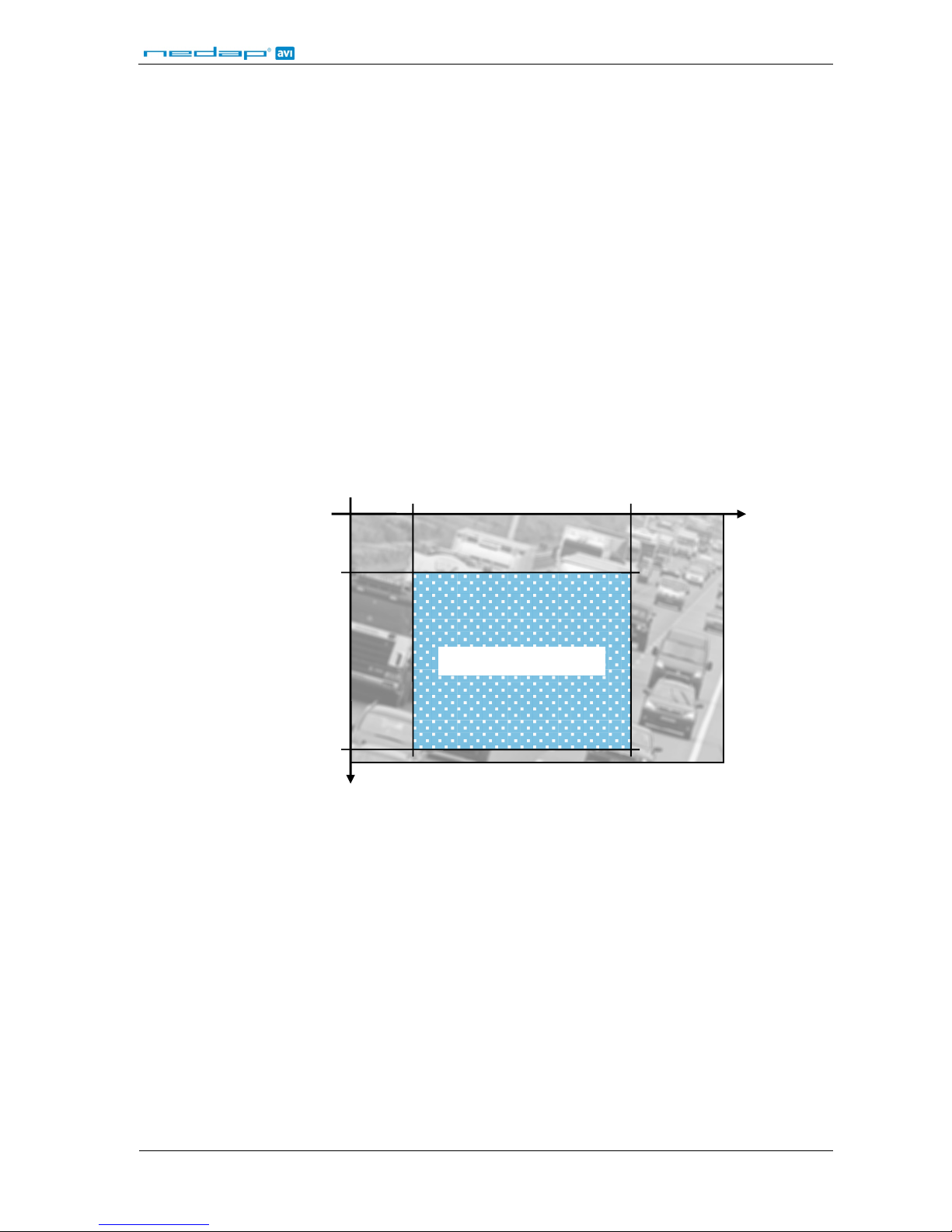
This section contains the coordinates of the number plate search area in the image. The search window is
displayed with a red border on the live image in the Camera OCR page. By setting the search window, the user is
allowed to exclude image zones where, supposedly, no number plate will ever be detected or to exclude image
zones where plate reading needn’t be executed.
Win MinX Pixel: The upper left X-coordinate of the plate searching window. See picture below.
Win MinY Pixel: The upper l e ft Y -coordinate of the plate searching window. See picture below.
Win MaxX Pixel: The lower right X-coordinate of the plate searching window. See picture below.
Win MaxY Pixel: The lower right Y-coordinate of the plate searching window. See picture below.
Sensitivity: This value may range from 2 to 8. Typically, used values are 4, 5 and 6. Higher
Sensitivity values cause higher reco gnition sensitiv ity but also ca use a higher chance
of wrong readings. It is recommended to avoid higher sensitivity values unless these
are absolutely necessary.
0
X
0
Y
Plate searching window
MinX MaxX
MinY
Max
Page 13

ANPR
© Nedap AVI, P.O. Box 103, NL-7140 AC GROENLO Page 13 of 27
Char Size Pixel
These parameters represent the size of the plate characters the OCR video camera is to recognize. The maximum
and minimum character sizes should be empirically set upon installation, in order to check whether the OCR
recognizes the number plates.
Min Width: The minimum character width in pixels.
Max Width: The maximum character w id th in pixels.
Min Height: The minimum character height in pixels.
Max Height: The maximum character height in pixels .
Procedure for adjus ting the chara cter size settings:
1. In the Camera OCR page, take a shot of the number plate under the actual conditions later used in the
ANPR system.
2. Use the Result Position setting in order to activate the OCR results image overlay feature.
3. Now, when the plate reading occurs, on the image is displayed not only the number plate but also the
character size in pixels.
4. Enter these size values in the Plate Reader page, using the exact minimum and maximum values
displayed on the screen during the live capture from the most distant vehicle position (min. size) and
the nearest vehicle position (max. size).
5. If number plate reading is not reached, try and set a higher character maximum size, until a valid
reading is reached.
6. In the Result web page, it is possible to read the character size of last detected vehicle. This is useful
when checking the validity of the character size setup during system operation.
Note: Character size adjustment is important and can significantly improve the overall system performance.
Plate Format
Max Jolly Chars: This feature allows setting the maximum number of plate characters the ANPR reader
is allowed not to recognize within the number plate. If set to 0 (zero), the reading is
valid only if the ANPR recognizes every character of the number plate. If set 1 or 2
(maximum value), the ANPR will consider the reading valid while the unrecognized
characters are replaced by a Joll y character – represented by the # symbol. Number
plate readings with jolly characters generate an OCR_READ event.
Plate With Separator: If enabled (YES) then an underscore character ('_') is inserted between the number
plate character groups. Only for German plates (DEU).
Plate Rotation %: This allows setting the plate rotation. This may improve the ANPR performance when
installed under an angle. The value is set in the range from 0 to 100%. When set to -1
the ANPR will automatically learn the plate rotation from the first 20 number plates.
Page 14

ANPR
© Nedap AVI, P.O. Box 103, NL-7140 AC GROENLO Page 14 of 27
Temporal Integration
The ANPR system processes multiple images for each vehicle, which allows for higher OCR reading effectiveness
and reliability. Section Temporal Integration contains the parameters for managing the whole packet of
processed images for each single event.
Max Time Transit: This parameter is relevant only in FREE-RUN mode. This is the maximum time period
allowed for any number plate transition. If, for example, this parameter is set to
1000ms, then the ANPR system reads the number plate once, but will wait 1000ms
before generating the event.
During this time, the system keeps grabbing and processing images of the same
vehicle whose number plate was read. This allows for a highly reliable number plate
reading process.
During this same interval, the system may detect a vehicle with a different number
plate number. In that case a new event is immediately generated (no waiting for the
1000ms interval to expire). The images subsequently acquired and processed must
be related to the new event.
The MaxTimeTransit value should be set to the highest possible value while of course
complying with the specific installation requirements. Setting a too low
MaxTimeTransit value means less images are processed for the same vehicle, which
leads to lower reliability in OCR reading.
Min Time Same Plate (Enable Multi Out Same Plate = 0):
It represents the minimum time in milliseconds during which the camera will not
generate an event even if the number plate has already been recognized. In other
words, during this time a previously recognized number plate does not need be in
the ANPR field of action in order to generate another event. If the vehicle remains in
the ANPR field of action, the same plate recognition event is generated only once.
Min Time Same Plate (Enable Multi Out Same Plate = 1):
It represents the length of time in milliseconds that must elapse before generating a
new recognition event associated with a plate that was already recognized. In this
case, if vehicle remains within the camera field, then the ANPR system will repeat
generating a recognition event every Min Time Same Plate.
Image Selection Mode: Indicates the selection mode of the image containing the recognized plate. Possible
values are: FIRST-PLATE, LAST-PLATE, BIGGEST-PLATE or BEST-LUMINANCE.
5.2.4 DIGITAL TRIGGER
This page configures the digital input to trigger image processing on the ANPR system. When the ANPR is
configured to FREE RUN mode, the settings below are ignored. The Digital Input Trigger page contains the
following fields:
Start Input Num: Set the number of the digital input a ssociated with the start trigger.
Start Input Edge: Set the start trigger state (rising edge or falling edge).
Stop Input Num: Set the number of the digital input associated with the stop trigge r .
Stop Input Edge: Set the stop trigger state (rising edge or falling edge).
GateTimeMax: It allows setting the value, in milliseconds, of the maximum period between start and
stop of the trigger. The values may range from 40 to 30000 (=30 seconds).
Trigger Shift Time: It allows setting a delay to be applied to the start and stop triggers. This may be
useful in order to insert a delay between trigger detection and processing
initialization. Specify value in milliseconds. Default 0 is no delay.
Page 15

ANPR
© Nedap AVI, P.O. Box 103, NL-7140 AC GROENLO Page 15 of 27
5.2.5 CHECK LIST
The ANPR features 2 check lists called A and B. The configuration of check list A and B are identical. These check
lists can also be referred to as a white-list or black-list.
These check lists can be stored either on the internal flash memory of the ANPR or on a remote ftp-server. The
check list is loaded into RAM memory upon ANPR start-up.
It is possible to modify and update in real time the number plate lists located in the ftp-server or in the internal
flash memory of the ANPR unit. To load the updated list into the RAM memory, press the 'Reload List'-button.
Syntax Check List file contents
The check list file A and B containing number plate lists, must comply with the follo wing syntax:
Vehicle Number plate; Country; Comment string
The semicolon (' ; ') is used to separate the fields.
Irrelevant spaces are ignored.
The Country field should contain the 3 character capital code as found in appendix A.
The comment string maximum length is 64 characters. Longer comment strings will be truncated.
Every line (including the last line) must be terminated with a carriage-return.
Example:
46HVR9;NLD;Ferrari 599 GTO
ZLSZ17;NLD;Fiat Cinquecento
AB123HK;ITA;
Note: The maximum check file size is 200kbytes. This approximately holds up to 10000 number plates, depending
upon number plate and comment lengths.
General
Enable: Enables the use of the check list.
List Location: Select the check list location.
FFS is the ANPR internal Flash File System.
FTP refers to a list residing on an external server.
FTP Server
File Name: It allows setting the check list file name. The file name and its extension must
correspond to the file name residing on the server.
FTP IP: The ftp-server IP address.
FTP Username: Username of the ftp-server user.
FTP Password: Password of the ftp-server user.
FTP Port: Port number of the ftp- server. Usually port number 21.
FFS (Flash File System)
Upload procedure - upload check file from PC to ANPR:
Click the Browse-button and select the check file (located on the PC or on the local network). After the file has
been selected, click the 'Upload List'-button to send the file to the ANPR.
Download procedure - download check file from ANPR to P C:
Click the 'Download List'-button to download the check list from the ANPR (as .TXT file). This list is read from the
ANPR's RAM memory.
Page 16
ANPR
© Nedap AVI, P.O. Box 103, NL-7140 AC GROENLO Page 16 of 27
5.2.6 EVENTS / ACTIONS
The ANPR generates a number of different of events. It is possible to associate one or more actions to each event.
The Events and Actions matrix is used to configure and assign actions to the events.
On the left side of the matrix the events are shown.
OCR Read: Event number plate recognized.
OCR Not Read: Event number plate re ad partially. Partiall y means that groups of cha racter were read
that do not comply with any syntax supported by OCR libraries of the version in use.
Typically, an OCR Not Read event is generated when the detected number plate can't
be properly read due to dirt or damage. This event is also generated if the number
plate's Country of Origin is not supported by the firmware version.
OCR No Plate: Event image processed containing no number plate – this event is generated in
trigger mode only. See chapter 5.2.1 for a more detailed description of the various
available operating modes.
Match on list A: Event n u mbe r pl a te number recognized and a match found in check list A.
No match on list A: Event number plate number recognized but no match found in check list A.
Match on list B: Event number plate number recognize d and a match found in check l ist B.
No match on list B: Event number plate number recognized but no match found in check list B.
Start trigger: Start trigger event (either digital or ethernet).
Stop trigger: Stop trigger event (either digital or ethernet).
The matrix contains the following icons (no icon is shown in case the event/action pair is not possible):
Icon indicating that the corresponding action is assigned to the event.
Icon indicating that the ac tion is disabled.
In order to enable, disable or configure an event action, it is sufficient to click the icon as shown above. This will
access the user to the Configuration page that contains all action parameters and allows enabling/disabling the
action itself.
The Configuration page allo ws setting ea ch action para meters u sing configur ation TAGS i.e. strings s tarting with
a % symbol. Click the context HELP buttons in each web page to view the available TAGS. The ANPR translates
these TAGS into their corresponding value. Click on the Help button next to the configuration field to get
detailed information about the supported tags.
For example: Let's think of how to form the name of the file to which the image will be saved. If the file name was
set to %PLATE a nd the number plate is HG542ER then the file name is HG542ER.JPG (if image is saved to JPG
format).
%PLATE à HG542ER.jpg
When using TAGS not provided by the software, then they are not translated. For example, the %TEST and %_
tags are not supported , so that:
%TEST%_%PLATE à TEST_HG542ER.jpg
Page 17
ANPR
© Nedap AVI, P.O. Box 103, NL-7140 AC GROENLO Page 17 of 27
5.2.6.1 ACTION: SAVE IMAGE TO FTP SERVER
This function allows saving the images of vehicle detected by the ANPR to a remote ftp- server. See chapter 4.1
for details about connecting the ethernet interface.
Enable: Select YES to enable save to an ftp-server.
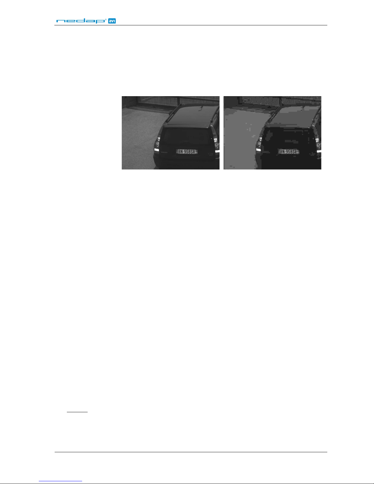
Jpeg Quality: Jpeg image quality. The value may range from 1 to 100 where 1 is the maximum
compression level (lowest quality) and 100 is the minimum compression level
(highest image quality). Suggested values from 50 to 90.
Example jpeg imag e quality 90. Example jpeg image quality 5.
Crop Image: This setting allows sending to an ftp-server a crop of the full image. The crop is cut
around the number plate. Available sizes are: 320x240, 640x480, 800x600 and
1024x768. Sending an image crop instead of the full image saves space on the
storage server and cuts down on transmission time on the network (this is useful
when working with low bandwidth networks).
Path Name: Specify the folder name where the image is saved. It is necessary to use appropriate
tags to indicate this folder name. For example, use the %DATE tag in order to use the
date of grabbing as folder name.
If the specified directory does not exist, it is automatically created.
File Name: Specify the image file name. It is necessary to use appropriate tags to indicate this file
name. For example, use the %PLATE tag in order to insert the read number plate in
the name.
Text Position: Specify the position of a text window inside the saved image. This window contains
the information entered in Text Value. The allowed values are: TOP-LEFT, TOP-RIGHT,
BOTTOM-LEFT, BOTTOM-RIGHT and DISABLED.
Text Options: It allows enabling the option NOT-OVER-PLATE. This option moves automatically the
text window when positioned over the plate, in order to not cover the plate.
Text Value: Specify the information to be included in the image. It is necessary to use appropriate
tags to provide this information. Click the Help-button to check the supported tags.
FTP IP: The ftp-server IP address.
FTP Username: Username of the ftp-server user.
FTP Password: Password of the ftp-server user.
FTP Port: Port number of the ftp- server. Usually port number 21.
FTP Passive Mode: It allows enabling (YES) the passive modality (PASV) for data transferring.
Buffering on SD: In case of network failure and Buffering on SD is enabled, the camera will save all
data regarding the actions. When the network connection is restored, the ANPR will
manage automatically all data stored, freeing the memory. The saving is based over a
circular buffer. In case of full memory the ANPR will overwrite oldest data.
FTP LINK
: Click on this FTP-LINK to directly access the ftp-server. This hyperlink uses the FTP
parameters entered above. This is useful to check whether the ftp-server is operating
properly.
Page 18

ANPR
© Nedap AVI, P.O. Box 103, NL-7140 AC GROENLO Page 18 of 27
5.2.6.2 ACTION: SAVE TO DB
If enabled, this feature allows creating and automatically updating on a remote ftp-server a text file in CSV format
(CSV = Comma Separated Values) containing information about every detected vehicle by the ANPR. See chapter
4.1 for details about connecting the ethernet interface.
Enable: Select YES to enable updating the database with the generated events.
Path Name: Specify the folder name where the database is saved. It is necessary to use
appropriate tags to indicate this folder name. For example, when using %DATE, a
new folder is created each day.
File Name: Specify the name of the database to be updated with the event info. For example
when using %DATE a new file is generated each day. The file name is the date on that
day (e.g.: 2011-07-28.CSV).
Fields: Specify the database fields. For example:
%DATE;%TIME;%PLATE
CSV file contents:
2011-07-28;09-14-44-222;ZLSZ17-NLD
2011-07-28;09-14-44-222;46HVR9-NLD
FTP IP: The ftp-server IP address.
FTP Username: Username of the ftp-server user.
FTP Password: Password of the ftp-server user.
FTP Port: Port number of the ftp- server. Usually port number 21.
FTP Passive Mode: It allows enabling (YES) the passive modality (PASV) for data transferring.
Buffering on SD: In case of network failure and Buffering on SD is enabled, the camera will save all
data regarding the actions. When the network connection is restored, the ANPR will
manage automatically all data stored, freeing the memory. The saving is based over a
circular buffer. In case of full memory the ANPR will overwrite oldest data.
FTP LINK
: Click on this FTP-LINK to directly access the ftp-server. This hyperlink uses the FTP
parameters entered above. This is useful to check whether the ftp-server is operating
properly.
5.2.6.3 ACTION: PULSE OUT
If enabled, activates a digital output for a specified time period. See chapter 4.4 for details about the digital
outputs.
Enable: Select YES to enable activation the digital output.
Output Number: Number of the digital output to be activated.
Delay Time: Delay (in milliseconds) to be applied prior to the actual activation of the output.
Pulse Time: The time period (in milliseconds) for which the digital output will be activated.
Page 19

ANPR
© Nedap AVI, P.O. Box 103, NL-7140 AC GROENLO Page 19 of 27
5.2.6.4 ACTION: SEND MESSAGE TO RS485 SERIAL PORT
It is possible to send messages to the RS485 serial port. Tags are used to define the content of the message sent.
Before using the serial ports, it is necessary to configure them in a web page found in the system section. See
chapter 5.3.3. See chapter 4.3 for details about connecting the RS485 serial interface.
Enable: Select YES to enable sending messages to the RS485 serial port.
Message: Specify the message content syntax. This is done using tags. Click the Help-button to
check the supported tags. It is possible to inserts bytes using hexadecimal coding.
This makes data packet building more flexible than when using alphanumeric
characters only.
For example: in order to send the number plate number string followed by the two
character sequence CR (carrier return) and LF (line feed) as terminators, the message
field is to be set as follows: %PLATE%0x0D%0x0A where 0x0D and 0x0A are the
hexadecimal codes of CR and LF, respectively.
5.2.6.5 ACTION: SEND MESSAGE TO TCP/IP SOCKET
If enabled, this action will send a message to a TCP/IP socket connection. Tags are used to define the content of
the message sent. See chapter 4.1 for details about connecting the TCP/IP ethernet interface.
See the ANPR ethernet programmer's guide which describes the TCP/IP message data format.
Enable: Select YES to enable sending messages to a TCP/IP socket.
Message: Specify the message contents. This is done using tags. Click the Hel p-button to che ck
the supported tags. It is possible to insert in the packet either data (such as number
plate number, date and time) or the JPEG image of the vehicle: %IMAGE_BW.
The data is sent on the network using a message header that includes the overall
number of data contained in the message.
Jpeg Quality: Jpeg image quality. The value may range from 1 to 100 where 1 is the maximum
compression level (lowest quality) and 100 is the minimum compression level
(highest image quality). Suggested values from 50 to 90.
Server IP: IP address of the server.
Server Port: Server listening port.
Reuse Connection: NO: the socket connection is opened and closed upon every message.
YES: the socket connection is opened upon sending the first message and is kept
active. The connection is shut down if unused for 15 minutes.
Regardless of mode configuration, the TCP connection will close and open a new TCP
connection when problems occurred while sending data. This means the receiver
should be steadily ready to accept new TCP connections.
Buffering on SD: In case of network failure and Buffering on SD is enabled, the camera will save all
data regarding the actions. When the network connection is restored, the ANPR will
manage automatically all data stored, freeing the memory. The saving is based over a
circular buffer. In case of full memory the ANPR will overwrite oldest data.
Page 20
ANPR
© Nedap AVI, P.O. Box 103, NL-7140 AC GROENLO Page 20 of 27
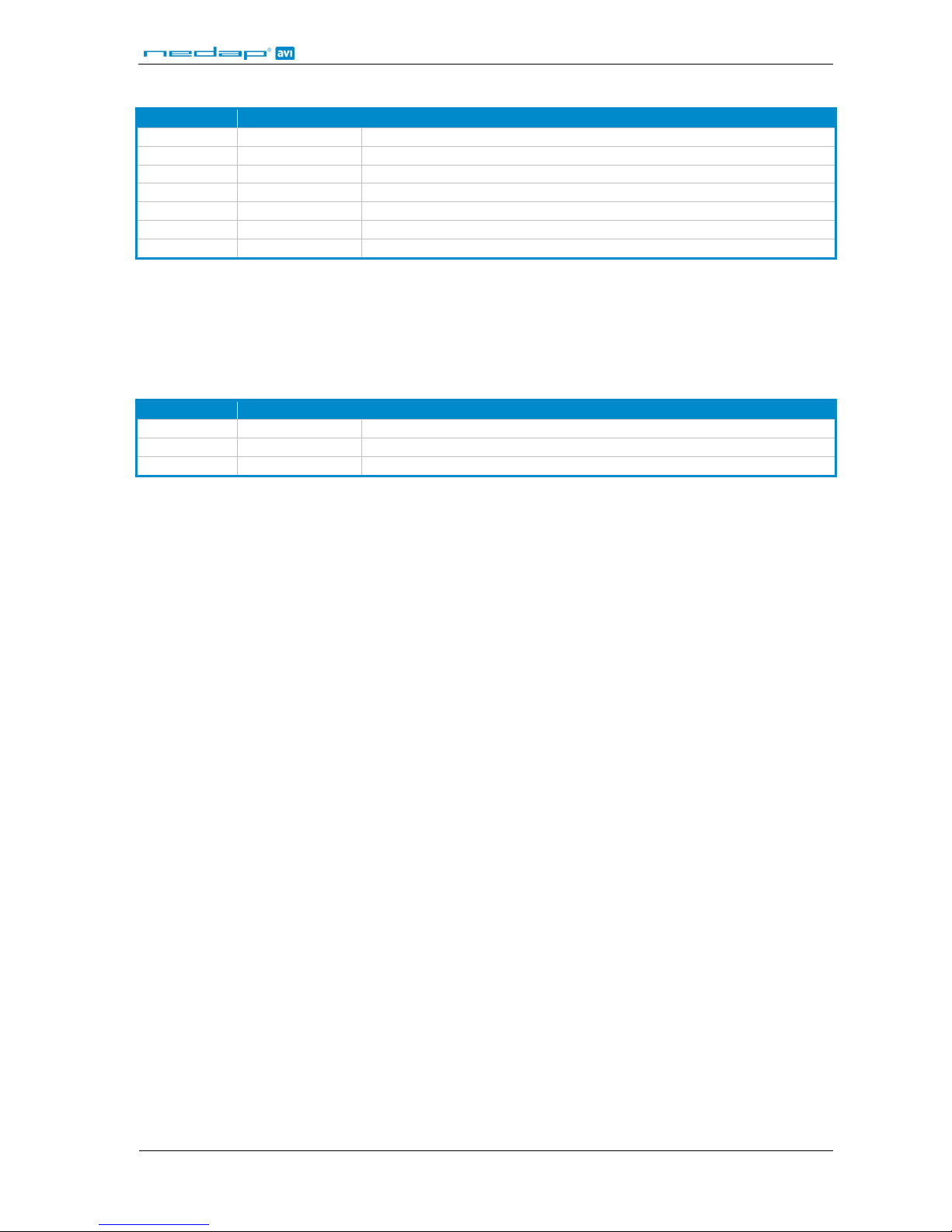
Network data packet format:
Value Length (in bytes) Description
24 4 Header size in bytes. Always set to 24 (=0x00000018).
<CMD> 4 Command code. Always set to 40000 (=0x00009C40).
0 4 Not used
0 4 Not used
<ERR> 4 Error code ( 0=no error).
<LEN> 4 Data size in bytes. 32-bit aligned. Header not included.
<DATA> <LEN> Packet data. Containing the tag defined in the Message field above.
The packet data contains the tags defined in the Message field. Every tag is defined by a tag-identifier and a tagsize indicator. The packet may contain any number of tag-fields. Tag-fields are arranged depending on the ANPR
firmware. This may as well change when using a different firmware version. For this reason, when searching fo r
tag-fields in a received packet, the server should scan all tag-fields regardless of their position inside the received
message. This programming method allows for software compatibility with future firmware versions.
Network packet tag-field format:
Value Length (in bytes) Description
<TAG-ID> 4 Tag-identifier
<TAG-LEN> 4 Tag-size in bytes
<TAG-DATA> <TAG-LEN> Tag field contents
In the web interface it is possible to select the tags to attach to the message sent to the TCP server. To define the
data to be attached, tags are used. For example, use %PLATE in order to attach the string with th e number plate
number. Refer to the table below in appendix B for an overview of the available tags on the web interface, their
description and tag-identifier code included in the message.
5.2.6.6 ACTION: SAVE IMAGE TO SD MEMORY
If enabled, save data on a partition of the SD memory regardless of network status. In this case the saving is NOT
managed with circular bu ffer.
Enable: Select YES to enable saving images on SD memory.
Jpeg Quality: Jpeg image quality. The value may range from 1 to 100 where 1 is the maximum
compression level (lowest quality) and 100 is the minimum compression level
(highest image quality). Suggested values from 50 to 90.
Crop Image: This setting enables a crop of the full image. The crop is cut around the number plate.
Available sizes are: 320x240, 640x480, 800x600 and 1024x768.
Path Name: Specify the folder name where the image is saved. The first part of the path is
mandatory %DATE%HOUR.
File Name: Specify the image file name.
Text Position: Specify the position of a text window inside the saved image. This window contains
the information entered in Text Value. The allowed values are: TOP-LEFT, TOP-RIGHT,
BOTTOM-LEFT, BOTTOM-RIGHT and DISABLED.
Text Options: It allows enabling the option NOT-OVER-PLATE. This option moves automatically the
text window when positioned over the plate, in order to not cover the plate.
Text Value: Specify the information to be included in the image. It is necessary to use appropriate
tags to provide this information. Click the Help-button to check the su pp orted tags.
Page 21

ANPR
© Nedap AVI, P.O. Box 103, NL-7140 AC GROENLO Page 21 of 27
5.2.7 IMAGE RESULT
This Image Result page displays image and grabbing data of the last detected vehicle. The page is automatically
and periodically reloaded so it is possible to keep open and view in real time the system results. Since the page is
periodically being reloaded, it might happen that not all system-detected vehicles are displayed. It may happen,
with heavy traffic, that the refresh period is not capable of showing all vehicles that actually have passed.
Next to the image, the following data is displayed:
PLATE: The number plate ass ociated with the recognition.
COUNTRY: Three-character str in g indicating the plate's country of origin. See appendix A.
N. READ: The number of images containing the read plate.
CHAR WIDTH/HEIGHT: The character width and height, in pixels. Helpful whe n adjusting the minimum and
maximum character size in the Plate Reader settings page (see chapter 5.2.3).
SHUTTER: The exposure time, in microseconds, used for image grabbing.
STROBE: The infrared illuminator activ ity time, in microsecond s , u sed for image grabbing.
GAIN: The gain used for ima ge grabbing.
DATE/TIME: Date and time at which the image was grabbed.
5.2.8 TEXT RESULT
The Text Results page displays the returned values of the OCR algorithm for each grabbed ima ge.
14/07/2011 14:46:38:643 ZLSZ17-NLD(7) Acq(Sh=1226ms, St=1000ms, G=284, GP=2, IL=50)
14/07/2011 14:46:38:643 YT57HB-NLD(5) Acq(Sh=1158ms, St=1000ms, G=284, GP=2, IL=50)
14/07/2011 14:46:38:643 NOTREAD Acq(Sh=1717ms, St=1000ms, G=284, GP=3, IL=50)
The text lines will contain the recognized number plate (if any), the corresponding date and time and the
shutter, strobe and gain parameters that were used during the image processing.
5.2.9 STATISTICS
This page contains the OCR statistics for the last 24 hours of operation.
The upper part of the OCR Statistics page contains the percentages recognized as READ, NOT READ or NO PLATE.
The lower part contains the percentage of readings for the 3 different points of image grabbing. This allows
viewing, at any time of the day, how many vehicles have been detected as well as what grabbing points were
used. Using this info rma tion, the user can evaluate whether the grabbing settings are correct and consistent and
calculate the recognition rate.
Page 22

ANPR
© Nedap AVI, P.O. Box 103, NL-7140 AC GROENLO Page 22 of 27
5.3 SYSTEM CONFIGURATION
5.3.1 NETWORK
The Network Settings page contains the following configuration fields:
Network
NetBiosName It allows setting the name of the ANPR device. It is possible to enter alphanumeric
values in this field. Spaces must be represented by "_" (underscore).
IpAddress It allows setting the IP address of the ANPR device.
NetMask It allows setting the network net mask.
Gateway It allows setting the gateway IP address.
DhcpEnable It allows enabling/disabling automatic acquisition of IP addresses.
Time Server
Syncro This feature enables/disables the synchronization to an external timeserver.
IpAddress Indicates the IP address of the time server which is used as reference to synchronize
the ANPR's internal clock.
GMT Offset Indicates the number of minutes to add to the time received from the time server, in
order to offset between "Greenwich Mean Time" and local time. This value is
expressed in minutes and can be negative. See
http://wwp.greenwichmeantime.com
for further details on time zones for different countries around the world.
Auto DST Automatically adjust clock for daylight saving changes. If set to YES, it a utomatically
handles switching between daylight-saving time and standard time.
5.3.2 HTTP USERS
Three user access levels are available:
• Superuser The superuser is allowed to access all system-enabled features, modify operational
parameters (setup) and assign access rights to other users.
• Administrator The administrator has the rights to modify any all operational parameters but is not
allowed to access the HTTP Users page.
• Guest Guest users are only allowed to view the system parameters.
Access to HTTP Users page is granted to the superuser only, who is allowed to enable, disable or delete users or
to assign new passwords. Up to ten administrator and/or guest users can be assigned to the system and only one
superuser account.
The HTTP Users page contains the configuration settings of the users who access the ANPR via a browser.
Server Port: The port number where the http server is open. Default value is 80.
Name: User's username.
Password: User's password.
Status: User's access level. Can be ADMIN, GUEST or DISABLED.
Page 23
ANPR
© Nedap AVI, P.O. Box 103, NL-7140 AC GROENLO Page 23 of 27
5.3.3 RS485 SERIAL PORT
It is possible to send messages to the RS485 serial port. The messages must be enabled in the Events / Actions
settings table. Tags are used to define the content of the message sent. See chapter 5.2.6.4.
Below the RS485 serial port configuration is shown:
Enable: It allows enabling or disabling communication through the serial port.
Baud rate: Serial port communication speed. Default 9600.
Parity: Serial port parity checking. Default NONE.
Data Bit: Serial port number of data bits. Default 8.
Stop Bit: Serial port number of stop bits. Default 1.
Message: Message protocol format. Default RAW format. This format syntax can fully be
specified using the web interface. See chapter 5.2.6.4.
Using the PROTOCOLLED format involves a message header, footer and acknowledge
packets. See packet formats below.
Wait ACK: It allows enabling/disabling the confirmation signal sent by the external unit upon
data receiving. Only when in protocolled mode.
Timeout ms: It allows specifying the time (in milliseconds) of waiting for an answer from the
external unit (only when in protocolled mode).
Retry Number: It allows s pecifying the number of times to resend unacknowledged messages to the
external receiving unit (only when in protocolled mode).
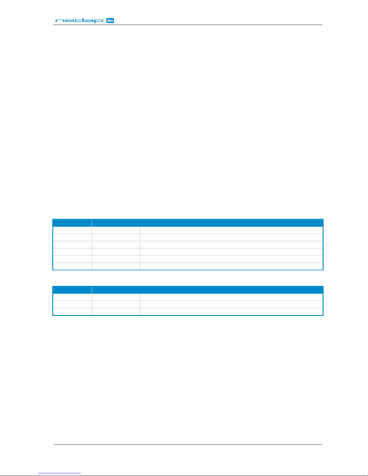
Protocolled data packet format:
Value Length (in bytes) Description
0x89ABCDEF 4 Open message code.
<ID> 4 Message ID number. Start at 1, incremented upon every message.
<LEN> 4 Data size in bytes.
<DATA> <LEN> Packet data. As specified in chapter 5.2.6.4.
<XOR> 1 Checksum. Xor of all previous bytes.
0x12345678 4 Close message code.
Protocolled acknowledge packet format:
Value Length (in bytes) Description
0xA5 1 Open message code.
<ID> 4 Message ID number. Must be the same as the ID of the received message.
0x5E 1 Close message code.
5.3.4 FIRMWARE
It is possible to update the ANPR firmware. The firmware update requires one file only, where operating system,
application and configuration files are integrated. The firmware file is distributed as a .bin-file.
Two possible update options are available:
7. Upgrade firmware keeping current settin gs .
8. Upgrade firmware with default settings (network s e ttings will remain unchanged).
Page 24

ANPR
© Nedap AVI, P.O. Box 103, NL-7140 AC GROENLO Page 24 of 27
Upload procedure:
Click the Browse-button below the preferred update method and select the firmware file (.bin-file). After the file
has been selected, click the Upload-button and confirm the operation. When the update completes, the user is
asked to reboot the device.
Notes: It is recommended, to use the internet explorer to update the firmware. Other browsers may not work or cause
problems with the ANPR firmware.
During the update it is very important to make sure the ANPR is not powered off.
Please do not close the HTTP connection until the download is completed.
Download procedure:
Press the Download-button to save a compressed bin-file containing the ANPR firmware and all its user defined
parameters. This feature is very useful when duplicating the same configuration onto another device or keeping
the file for backup purpose s. The bin-file can be directly loaded to an ANPR system, using either of the available
upgrade options.
5.3.5 DEVICE INFO
This page displays information about the ANPR firmware and hardware.
Image Sensor OCR = CCD_1300x1000_BW
Board Serial Number = 583447
Board code = 573
Board revision = 2
FPGA Version = 0
MAC Address = 0x0050C2BE1442
GMT Time & Date = 14.01.21, 13/07/2011, GMT offset: 0min, DST status: OFF
CPU time = 05.15.41
Temperature = Not Available
Flash file system size = 40312 KByte
Boot version = 2.7
TOS version = 4.29.13a
Firmware version = VEGA ACCESS 7.85 NLD-EU May 23 2011 16:25:00
OCR lib version = Tattile Plate Reader Ver.3.05.00
Buffering SD size = 3.8 GB (READY)
Storage SD size = 3.8 GB (READY)
5.3.6 DIGITAL I/O
The ANPR has a number of embedded digital inputs and outputs. Outputs are used for external monitoring
devices or for example control an electronic door lock. Inputs are used as trigger sources. It is possible to check
and modify the s tatus of d igital ou tputs. This function is useful when checking the cabling after installation. See
also chapter 4.4 for details about the digital i/o connections.
Digital input
Green input icon indicates that the input is high (gray is low).
Click on the Refresh-button to update the s ta tes of the icons .
Digital output
Red output icon indicates that the output is high (gray is low).
Click on the digital output icon to change its state.
Note: Only digital output 0 is wired on the ANPR.
Page 25

ANPR
© Nedap AVI, P.O. Box 103, NL-7140 AC GROENLO Page 25 of 27
5.3.7 SYS STATISTICS
This page contains the statistics about data sending from ANPR to external devices. The info in this page is very
useful upon installation as they help check the available bandwidths from ANPR to the data receiving servers.
In addition to this info, the page displays the statistics about synchronization with the SNTP server. These
statistics are updated when synchronization with time server is enabled (see chapter 5.3.1).
------------------------------------------------------------------------- | Time[sec] | Bandwidth[KB/sec] | Counters |
| Mean Max | Mean Min | Success | Failed |
------------------------------------------------------------------------- FTP Save Image | 0.00 0.00 | 0 0 | 0 | 0 |
FTP Save DB | 0.00 0.00 | 0 0 | 0 | 0 |
TCP Send Message | 0.01 0.03 | 5 1 | 6354 | 0 |
PNS Alarm | 0.00 0.00 | 0 0 | 0 | 0 |
--------------------------------------------------------------------------
------------------------------------------------------------------------- TIME SERVER SYNCRO
Synchronization disabled
--------------------------------------------------------------------------
5.3.8 SECURE DIGITAL
SD memory management is entirely automatic and transparent by the ANPR firmware. SD memory is used to
store data of ANPR generated events. The storage occurs only if the action planned for the event can't be
executed.
Let's consider for example the 'save image to ftp-server' action taken upon number plate reading event. In case
the ftp-server is not available (service not available or whatever network connection problem) then the image is
being stored to SD memory. As soon as the ftp-server is back to service, the image is automatically read from the
SD memory and sent to the server.
Before sending the image, the event/action matrix is checked. If the action is enabled, the image will be sent
while if disabled, the image will be deleted. In general, whenever action-related data are retrieved from the SD
memory, the relevant action parameters that were set via web page are always checked first so that the action is
executed according to these setting.
Let's assume for example that when saving the image to SD, the ftp-server IP is 192.168.0.100. If upon reading
the image from SD the server IP is 192.168.0.200, then the image will be sent to this IP address.
Page 26

ANPR
© Nedap AVI, P.O. Box 103, NL-7140 AC GROENLO Page 26 of 27
A COUNTRY CODES
Number plate countries are indicated with 3 characters. The table below shows the used country codes.
EUROPEAN PLATES
CODE COUNTRY CODE COUNTRY
AUT Austria LUX Luxembourg
BEL Belgium MLT Malta
BGR Bulgaria NLD Netherlands
CYP Cyprus POL Poland
DNK Denmark PRT Portugal
EST Estonia GBR Great Britain
FIN Finland CZE Czech Republic
FRA France ROU Romania
DEU Germany SVK Slovakia
GRC Greece SVN Slovenia
IRL Ireland ESP Spain
ITA Italy SWE Sweden
LVA Latvia HUN Hungary
LTU Lithuania CHE Switzerland
OTHER PLATES
CODE COUNTRY CODE COUNTRY
AUS Australia ARG Argentina
IND India COL Colombia
KSA Saudi Arabia TUR Turkey
MAR Morocco RUS Russia
MEX Mexico BHR Bahrain
RSA South Africa ISR Israel
UAE United Arab Emirates
SPECIAL PLATES
CODE COUNTRY
ADR Dangerous goods
CON Container (ISO code)
Page 27

ANPR
© Nedap AVI, P.O. Box 103, NL-7140 AC GROENLO Page 27 of 27
B TCP TAG IDENTIFIER OVERVIEW
TAG WEB Description TAG-ID TAG-LEN DATA TYPE
%DATE Date string YYYY-MM-DD. E.g. '2011-07-28' 14000 12 STRING
%TIME Time string HH-MM-SS. E.g. '12-34-56' 14001 16 STRING
%NETBIOSNAME NetBiosName. E.g. 'NEDAP_ANPR1' 14002 32 STRING
%PLATE Number plate, including country. E.g. '46HVR9-NLD' 14003 24 STRING
%PLATE_STRING Number plate, without country. E.g. '46HVR9' 14004 20 STRING
%PLATE_COUNTRY Number plate country. E.g. 'NLD'. See appendix A. 14005 4 STRING
%NREAD Number of times the number plate was read. 14006 4 INT32
%IMAGENAME Image file name. 14007 128 STRING
%IMAGEPATH image file path. 14008 128 STRING
%TRANSIT_ID Transit counter . 14009 4 INT32
%PLATE_MIN_X Upper left X-coordinate of the car plate rectangle. 14010 4 INT32
%PLATE_MIN_Y Upper left Y-coordinate of the car plate rectangle. 14011 4 INT32
%PLATE_MAX_X Lower right X-coordinate of the car plate rectangle. 14012 4 INT32
%PLATE_MAX_Y Lower right Y-coordinate of the car plate rectangle. 14013 4 INT32
%SPEED RFU 14014 4 INT32
%CLASS RFU 14015 4 INT32
%CLASS_STRING RFU 14016 32 STRING
%SN ANPR serial number. 14017 4 INT32
%DIRECTION RFU 14018 12 STRING
%NET_TRIG_ID String received using ethernet trigger. 14019 32 STRING
%IMAGE_BW Camera image in jpeg format. 14020 IMG-DIM BUFFER
%IMAGE_COL RFU 14021 IMG-DIM BUFFER
%OCRSCORE Score of the OCR regarding the number plate reading. 14022 4 INT32
All strings are null-terminated.
The values of IMG-DIM for BUFFER data are not necessarily multiples of 4 bytes, yet the occupied buffer space is
always a multiple of 4 bytes, this in order to keep structure alignment. For example: IMG-DIM is 34231 bytes. But
data buffer sent is larger (so as to keep 4 bytes-alignment) and the result is a 34232 bytes image. When using the
IMG-DIM value to skip to next datum of the message, this should not be overlooked.
 Loading...