

Page 1
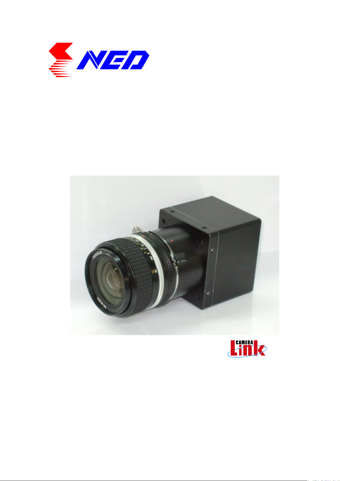
User’s Manual
Line Scan Camera
Type:SU2020/SU2025
NIPPON ELECTRO-SENSORY DEVICES CORPORATION
Page 2

NED
2
For Customers in U.S.A.
This equipment has been tested and found to comply with the limits for a Class A
digital device, in accordance with Part 15 of the FCC Rules. These limits are
designed to provide reasonable protection against harmful interference when the
equipment is operated in a commercial environment. This equipment generates, uses,
and can radiate radio frequency energy and, if not installed and used in accordance
with the instruction manual, may cause harmful interference to radio communications.
Operation of this equipment in a residential area is likely to cause harmful
interference, in which case the user will be required to correct the interference at his
or her own expense.
For Customers in the EU
This equipment has been tested and found to comply with the essential
requirements of the EMC Directive 2004/108/EC, based on the following
specifications applied:
EU Harmonised Standards
EN55022:2010 Class A
EN61000-6-2:2005
Warning
This is a class A product. In a domestic environment this product may cause radio
interference in which case the user may be required to take adequate measures.
Directive on Waste Electrical and Electronic Equipment (WEEE)
Please return all End of Life NED products to the distributor from whom the product
was purchased for adequate recycling and / or disposal. All costs of returning the
Product to NED are borne by the shipper.
SU2020/SU2025 UME-0021-03
Page 3
NED
3
Warning
If the product is not handled properly, this may result in
serious injury or possible death.
Caution
If the product is not handled properly, this may result in
physical injury or cause property damage.
Warning
Introduction
Thank you for purchasing NED’s Line Scan Camera. We look forward to your
continued custom in the future.
For safety use
For your protection, please read these safety instructions completely before
operating the product and keep this manual for future reference.
The following symbols appear next to important information regarding safe
product handling.
Safety precaution
Never disassemble or modify this product, unless otherwise specified to do so in
this manual.
When hands are wet, avoid handling this product and do not touch any of the
connection cable pins or other metallic components.
Do not operate this product in an environment that is exposed to rain or other
severe external elements, hazardous gases or chemicals.
If the product is not to be used for an extended period of time, as a safety
precaution, always unplug the connection cable from the camera unit.
If the product installation or inspection must be executed in an overhead location,
please take the necessary measures to prevent the camera unit and its
components from accidentally falling to the ground.
If smoke, an abnormal odor or strange noise is emitted from the camera unit, first
turn OFF power, then unplug the cable from the camera unit.
This product is not intended for use in a system configuration built for critical
applications.
UME-0021-03 SU2020/SU2025
Page 4

NED
4
Instructions before use
Only operate this product within the recommended environmental temperature
range.
Use only the specified power source and voltage rating.
Do not drop this product. Avoid exposure to strong impact and vibrations.
Install the camera unit in a well-ventilated environment, in order to prevent the
camera from overheating.
If the camera must be installed in an environment containing dust or other
particles, take required measures to protect the camera unit from dust adhesion.
Do not unplug the cable while power is being supplied to the camera unit. To
prevent product damage, always shut down the power supply before unplugging
the power cable.
When the surface of the camera window becomes dirty due to dust or grime,
black smudges appear in the displayed image. Use an air blower to remove the
dust particles. Dip a cotton swab into ethanol alcohol and clean the camera
window. Be careful not to scratch the glass.
Use of non-infrared lighting such as a daylight fluorescent lamp is recommended.
If halogen lighting is employed, always install an infrared filter into your system
configuration.
Please note that exposure to long wavelength light outside of the sensors visible
optical range can affect the image.
Sensitivity may fluctuate depending on the spectral response level of the light
source. In cases like this, changing the light source to one with a different
spectral response level may reduce this problem.
Please note that when the CCD is exposed to excessive quantities of light,
blooming can occur. (this product does not have an Anti-Blooming function)
For stabilized image capturing, turn ON the power supply and execute aging for
ten to twenty minutes before actually using the camera unit.
Do not share the power supply with motor units or other devices that generate
noise interference.
Do not disconnect the camera while rewriting the embedded memory.
When you change the exposure mode that is set at the NED factory, input control
signal (CC1) from the capture board.
SU2020/SU2025 UME-0021-03
Page 5

NED
5
Product Warranty
Warranty Period
The product warranty period, as a general rule, is two years from purchase;
however for detailed conditions please contact the sales representative for your
region/country.
However, in some cases due to the usage environment, usage conditions and/or
frequency of use, this warranty period may not be applicable.
Warranty Scope
Product repair will be performed on a Return To Manufacturer basis. On-site
maintenance will incur additional charges.
If defects in material or workmanship occur during the warranty period, the faulty
part will be replaced or repaired by us free of charge. Return shipping charges
must be paid by the sender. However, the following cases fall outside of the
scope of this warranty:
Exclusions from Warranty Coverage
We will under no circumstances assume responsibility for the following cases:
damage caused by fire, earthquake, other acts of a third party, other accidents,
negligent or intentional misuse by the user, or other usage under extraordinary
circumstances.
Damages (e.g. loss of business profits, business interruption, etc.) resulting from
use or non-use.
Damages caused by use other than as described in this document.
Damages resulting from malfunction due to a connected device.
Damages resulting from repairs or modifications performed by the customer.
Fault Diagnosis
As a general rule, in the first instance fault diagnosis should take the form of a
telephone call or an email to enable us to assess the circumstances of the
malfunction.
However, depending on the customer’s requests, we, or our agent, may require
an additional fee for this service.
UME-0021-03 SU2020/SU2025
Page 6

NED
6
Exclusion of Liability for Compensation for Missed Opportunities
Regardless of whether within the warranty period or not, our warranty does not
cover compensation for missed opportunities for our customers, or our
customers’ customers, caused by a fault of our products, nor for damage to
products other than our own, or related business.
Note about Product Usage
This product has been designed and manufactured as a general-purpose product
for general industry. In applications expected to be life-critical or safety-critical,
the installer or user is requested to install double or triple failsafe systems.
Repair Service Outline
The cost of dispatching engineers etc. for repair service is not included in the
price of purchased and supplied goods. On request, arrangements can be made
separately.
Scope of Repair Service
The above assumes business dealings and usage to take place in the
customer’s region / country. In cases of business dealings and/or usage outside
the customer’s region/country, separate consultation is required.
SU2020/SU2025 UME-0021-03
Page 7

NED
7
Table of Contents
1 Product Outline ......................................................................................... 10
1.1 Features ..................................................................................................................... 10
1.2 Applications ............................................................................................................... 10
1.3 Image Sensor ............................................................................................................. 12
1.4 Performance Specifications ..................................................................................... 12
2 Camera Setting and Optical Interface...................................... 14
2.1 Setting Camera .......................................................................................................... 14
2.2 Fixing Camera............................................................................................................ 14
2.3 Camera dimension .................................................................................................... 15
2.4 Optical Interface ........................................................................................................ 16
3 Hardware ........................................................................................................ 17
3.1 Camera Connection .................................................................................................. 17
3.2 Input / Output Connectors and Indicator ................................................................ 18
3.3 Connectors・Pin Assignments・Cables ................................................................... 19
3.4 Power Supply............................................................................................................. 22
4 Camera Control ......................................................................................... 23
4.1 Flow of Camera Control............................................................................................ 23
4.1.1 Command Overview ........................................................................................... 23
4.1.2 Command Format (PC to Camera Transmission) ........................................... 23
4.1.3 Reply Format (Camera to PC Transmission) ................................................... 24
4.1.4 Camera Control Commands .............................................................................. 25
4.1.5 Memory Setup Values (Factory Settings) ........................................................ 25
4.2 Details on Commands .............................................................................................. 26
4.2.1 Setting Gain......................................................................................................... 26
4.2.2 Setting CDS Gain ................................................................................................ 26
4.2.3 Setting Offset ...................................................................................................... 26
4.2.4 Switching video output ...................................................................................... 27
4.2.5 Switching trigger mode ..................................................................................... 27
4.2.6 Memory Save ...................................................................................................... 27
4.2.7 Memory Load ...................................................................................................... 27
4.2.8 Memory Initializing (Initializing Camera Settings) .......................................... 28
4.3 Startup ........................................................................................................................ 28
4.4 Saving and Loading Camera Settings .................................................................... 28
UME-0021-03 SU2020/SU2025
Page 8

NED
8
4.5 Serial Communication Settings ............................................................................... 29
4.6 Video Output Format ................................................................................................ 30
4.7 Exposure Mode and Timing Chart ........................................................................... 31
4.7.1 Free Run Mode .................................................................................................... 31
4.7.2 External Trigger (ExTrg) Exposure Mode ........................................................ 32
4.8 Setting Offset ............................................................................................................. 32
4.9 Setting Gain ............................................................................................................... 33
5 Confirming Camera Settings .......................................................... 34
5.1 Before Power-on ....................................................................................................... 34
5.2 After Power-on ........................................................................................................... 35
5.3 During Operation ....................................................................................................... 37
6 Sensor Handling Instructions ........................................................ 38
6.1 Electrostatic Discharge and the Sensor ................................................................. 38
6.2 Protecting Against Dust, Oil and Scratches .......................................................... 38
6.3 Cleaning the Sensor Window .................................................................................. 38
7 Troubleshooting ....................................................................................... 39
7.1 No Image .................................................................................................................... 39
7.2 Noise on Image .......................................................................................................... 41
7.3 Camera becomes hot ................................................................................................ 43
8 NCCtrl ............................................................................................................... 44
8.1 Overview .................................................................................................................... 44
8.2 System Requirements .............................................................................................. 44
8.3 Install .......................................................................................................................... 45
8.4 Uninstall ..................................................................................................................... 45
8.5 Operation ................................................................................................................... 45
8.5.1 General description ............................................................................................ 45
8.5.2 Starting NCCtrl .................................................................................................... 46
8.5.3 Open the control setting file .............................................................................. 47
8.5.4 Selecting interface and Timeout setting .......................................................... 47
8.5.5 Connect ............................................................................................................... 50
8.5.6 Disconnect and exit program ............................................................................ 50
8.5.7 Check the contents of communication ............................................................ 51
8.5.8 Export Parameters to text file ........................................................................... 51
8.5.9 Import Parameters from text file ....................................................................... 52
SU2020/SU2025 UME-0021-03
Page 9

NED
9
8.6 Control ........................................................................................................................ 52
8.6.1 Gain and Offset ................................................................................................... 53
8.6.2 Clock, Video output, Video shift, Exposure mode .......................................... 54
8.6.3 Exposure time ..................................................................................................... 54
8.6.4 Binning ................................................................................................................ 54
8.6.5 Camera Memory .................................................................................................. 54
8.6.6 Calibration ........................................................................................................... 55
8.6.7 Level Correction ................................................................................................. 55
8.6.8 Test Pattern ......................................................................................................... 55
8.6.9 Line Delay ............................................................................................................ 56
8.7 Software Upgrades.................................................................................................... 56
8.7.1 NCCtrl upgrades ................................................................................................. 56
8.7.2 Adding/Replacing control setting file............................................................... 56
8.7.3 Adding/Replacing the interface Plug-in ........................................................... 56
8.8 Data Transmission Programming ............................................................................ 56
8.9 NCCtrl Troubleshooting............................................................................................ 57
8.9.1 You can not change the exposure time with NCCtrl ....................................... 57
8.10 Attention on use ...................................................................................................... 57
9 Others ................................................................ ............................................... 58
9.1 Notice.......................................................................................................................... 58
9.2 Contact for support ................................................................................................... 58
9.3 Product Support ........................................................................................................ 59
Revision History............................................................................................... 60
UME-0021-03 SU2020/SU2025
Page 10

NED
10
1 Product Outline
1.1 Features
High speed readout(25MHz:SU2025,20MHz:SU2020)
High resolution(2048 pixels)
Single power source DC12V for operation
Easy connection with a variety of frame grabber boards via Camera Link
interface
Easy control of gain / offset / video output (8-/10-bit) with external software.
High responsivity and low noise
Flat-field correction - minimizes lens vignetting, non-uniform lighting and
sensor FPN and PRNU
Low power consumption (20% decrease from NED old camera)
1.2 Applications
Inspection of Transparent panels and PCBs
Inspection of high speed moving objects
Flat panel display inspection
Inspection of glass and sheet-like objects
Printed circuit board inspection
This camera utilizes an Intelligent Transportation System
Outdoor surveillance
SU2020/SU2025 UME-0021-03
Page 11
NED
11
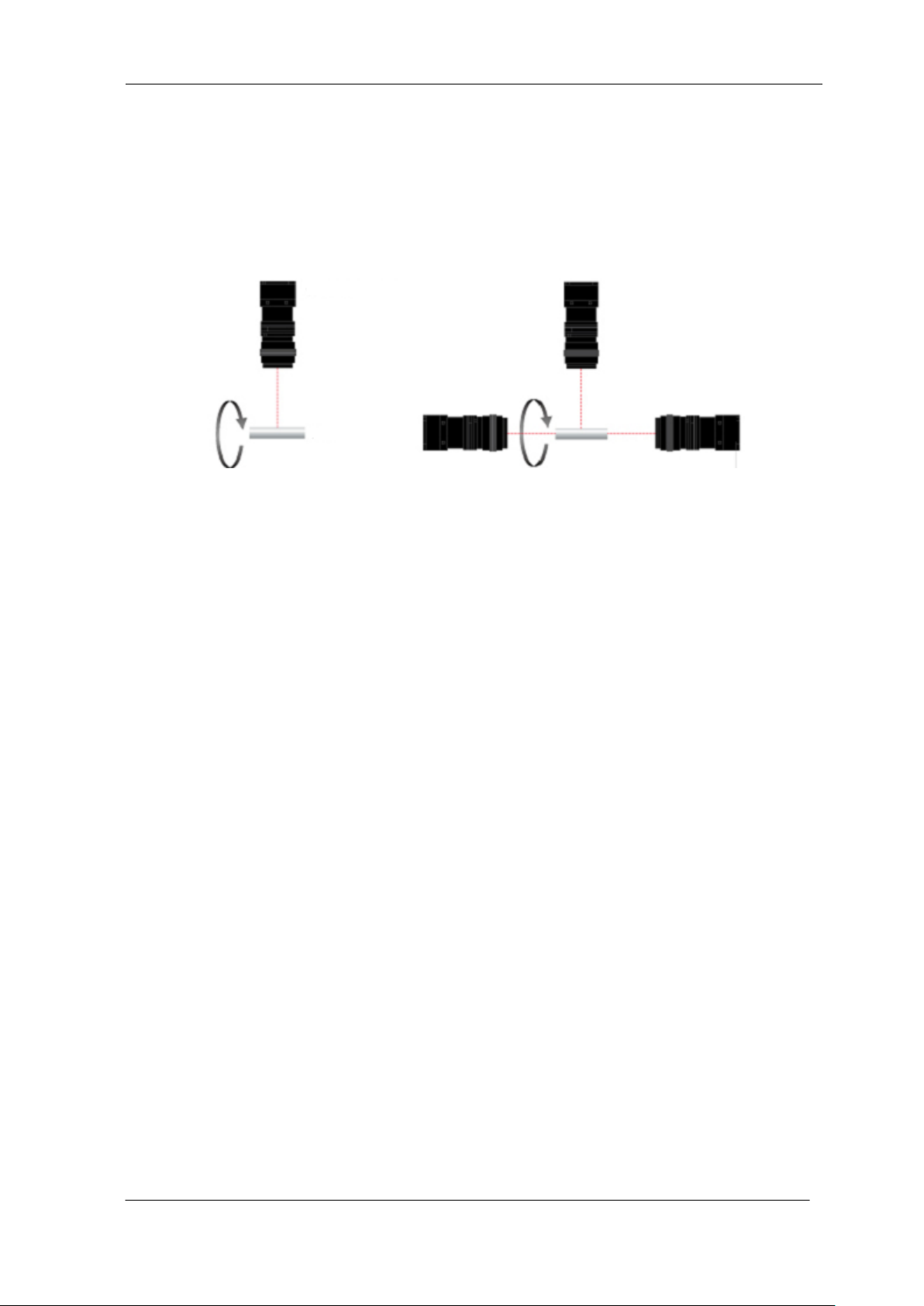
Metallic part of cylinder and conical geometry (surface and roller end face)
・Automobile component ・Architectural reinforcement parts
・Various pin parts
Typical detection item
・chip ・dent ・scratch ・chip of roller end face ・external dimensions
Device specification
1.Camera: Line scan camera of number of 2048 pixels
2. Controller: Dedicated software for PC system
Line scan Camera
Object of inspection
■ Example of using of one camera.
(Inspection of only surface)
■ Example of using of three cameras.
(Inspection of surface and roller end face)
An example of Visual Inspection of PCBs is shown below.
Figure 1-2-1 Visual Inspection of PCBs
Object of inspection (example)
UME-0021-03 SU2020/SU2025
Page 12
NED
12
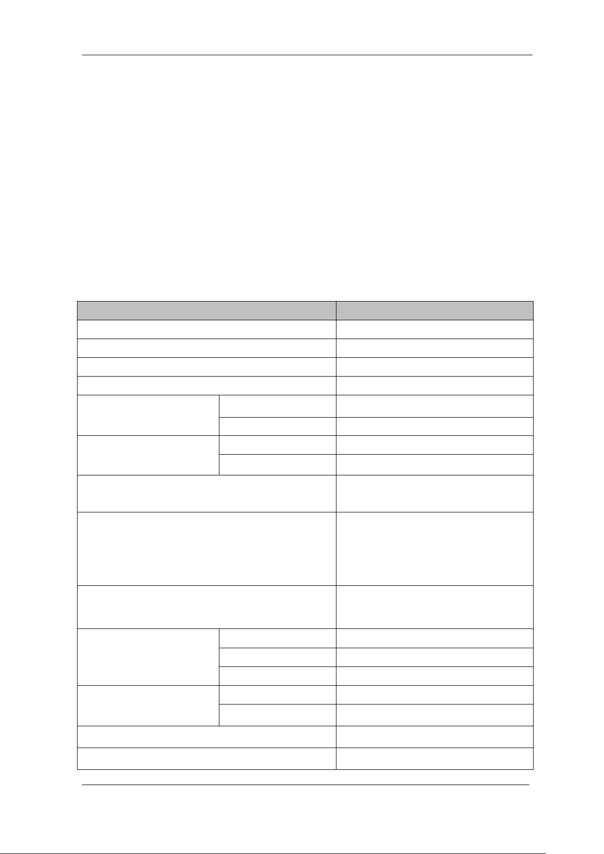
Items
Specifications
Number of Pixels
2048
Pixel Size H x V (μm)
14x14
Sensor Length (mm)
28.6
Spectral Responsivity (nm)
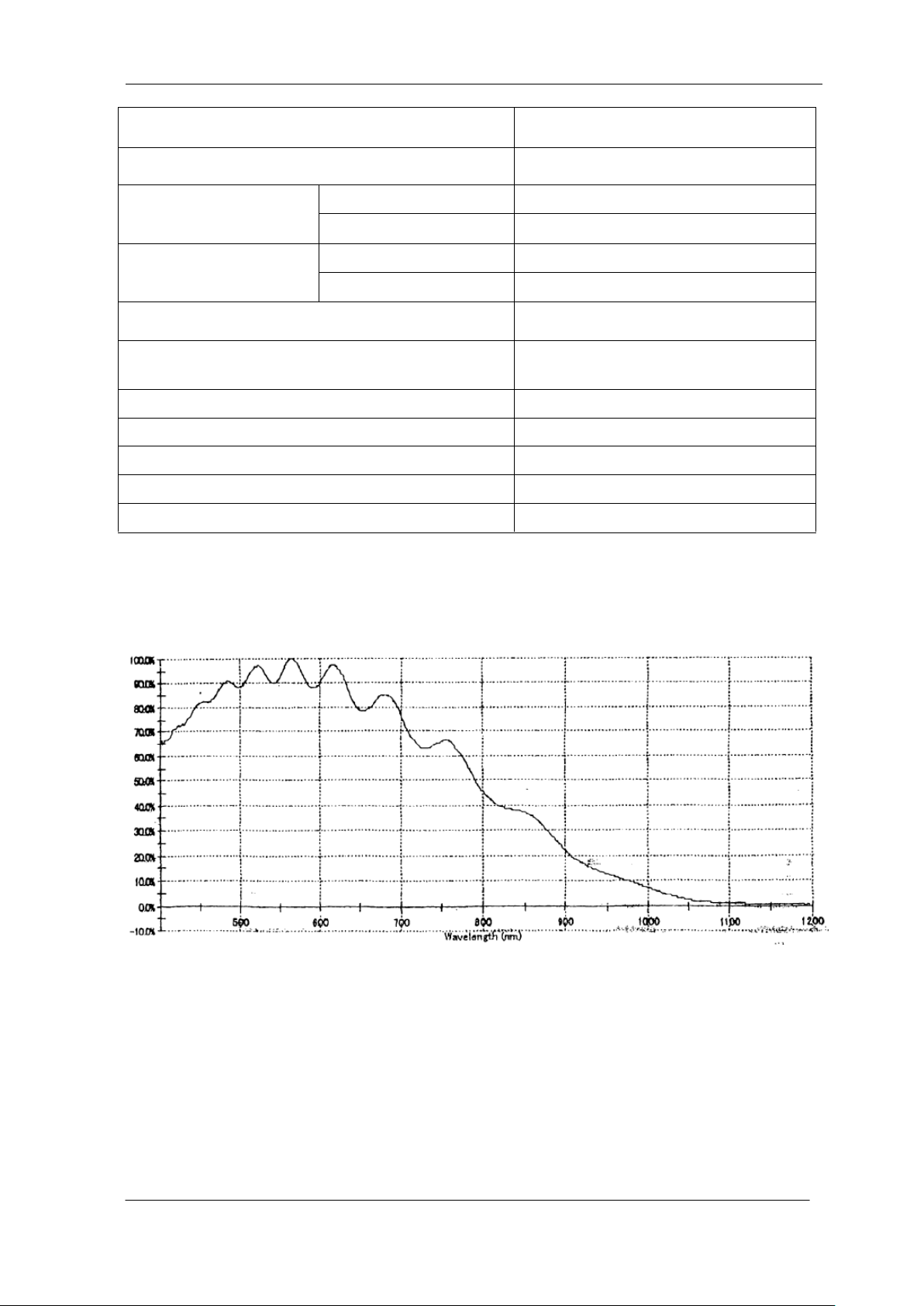
400~800 *Peak 567
DataRate (MHz)
SU2025
25 [Fixed]
SU2020
20 [Fixed]
Scan Rate
(μs) / [kHz]
SU2025
88 / [11.4]
SU2020
110 / [9.1]
Saturation Exposure (lx・s) (typically)
0.0555
Responsivity (V/ [lx・s]) (typically)
*Analog 5V Conversion Sensitivity
PGA Gain 0dB,Ta=25℃,
Daylight Fluorescent Light
90
Gain Adjustable Range
0 ~ 21(MAX.30dB In using CDS)
※0.03125dB/STEP
Offset Adjustable Range
(DN)
8 bit/tap
0 ~ 19 ※1LSB/STEP
10 bit/tap
0 ~ 76 ※4LSB/STEP
12 bit/tap
0 ~ 304 ※16LSB/STEP
Video output Camera Link
Format
Camera Link Base line 8,10,12bit
Protocol
Camera Link Base Configuration
PRNU (Photo Response Non Uniformity)
3%
Random Noise (DN)
20 (Minimum gain 10bit)
1.3 Image Sensor
The camera uses with a maximum data rate of 25MHz(SU2025)・20MHz(SU2020)
to acquire high responsivity and superior quality images.
The pixel size is 14μmx14μm. SU2025 outputs 2048 pixel data through
25MHz,SU2020 outputs 2048 pixel data through 20MHz.
1.4 Performance Specifications
The Performance Specifications are shown below. Unless otherwise specified,
the data shown is when the camera is operating at the maximum scan rate.
Table 1-4-1 Performance Specifications
SU2020/SU2025 UME-0021-03
Page 13
NED
13
Control Input
CC1: External Synchronizing Signal
[start signal]
Serial communication Control
SerTC、SerTFG
Master Clock (MHz)
*only internal clock
SU2025
50
SU2020
40
Connectors
Data/Controller
3M: MDR26 [Camera Link]
Power Supply
Hirose: HR10A (4Pin)
Lens Mount
Nikon F Mount
Operating Temperature (˚C)
No Condensation
0 to 50
Power Supply Voltage (V)
DC 12 [+/-5%]
Consumption Current (mA) (typically)
270 [DC12V]
Size W x H x D (mm)
64x70x91.7 (*see section 4)
Mass (g) (Camera only)
< 410
Special instruction
Camera Link Interface
The spectral Responsivity is shown below.
UME-0021-03 SU2020/SU2025
Page 14

NED
14
2 Camera Setting and Optical Interface
2.1 Setting Camera
Use the M4 screw holes or the screw hole for a tripod to set the camera.
2.2 Fixing Camera
Use the M4 screw holes (4 places at the front, 8 places at the side) to fix the
camera.
Or use the 1/4"-20UNC screw hole (the screw hole for a tripod, 1 place at the
side) to fix the camera.
If using the front panel M4 mounting holes, the screw length for fixing the camera
should be less than 6mm.
No X-, Y-axis orientation and tilt adjustment mechanism is available. Please
provide an adjustment mechanism yourself as necessary.
SU2020/SU2025 UME-0021-03
Page 15
NED
15
59.0
+0.0
-0.2
10.0
40.0
FB'=45.0
95.9
36.2
59.7
40.0
1/4"-20UNC(valid depth 6)
screw hole for fixing camera
M4 Depth 6 (4 parts)
50.0
32.0
CCD center pixel
35.0
50.0
CCD中心
CCD 1st Pixel
23.0
12.0
70.0
22.5
Camera Link Connector
10226-2210PE
24.0
64.0
24.0
15.0
LED
Power Supply Connector
HR10G-7R-4PB(73)
DC 12V
NIPPON ELECTRO SENSORY DEVICES CORP.
CAMERA LINK BASE
MADE IN JAPAN
SCAN
screw hole for fixing camera
M4 Depth 6 (8parts)
55.5
45.0
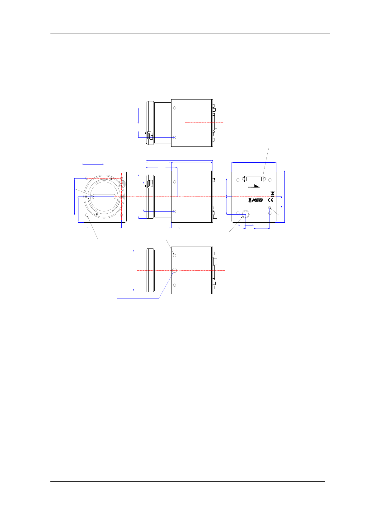
2.3 Camera dimension
The dimensions for camera are shown below.
Figure 2-2-1 Dimensions
UME-0021-03 SU2020/SU2025
Page 16

NED
16
2.4 Optical Interface
The amount and wavelengths of light required to capture useful images depend
on the intended use. Factors include the property, speed, the object’s spectral
characteristics, exposure time, the light source characteristics, the specifications of
the acquisition system and so on.
The exposure amount (exposure time x light amount) is the most important factor
in getting desirable images. Please determine the exposure amount after studying
what is most important to your system.
Keep these guidelines in mind when setting up your light source:
LED light sources are relatively inexpensive, provide a uniform field and
longer life span compared to other light sources. However, they also require a
camera with excellent sensitivity.
Halogen light sources generally provide very little blue relative to infrared
light (IR).
Fiber-optic light distribution systems generally transmit very little blue light
relative to IR.
Metal halide light sources are very bright but have a shorter life span
compared to other light sources.
Generally speaking, the brighter light sources, the shorter life span.
CCD image sensors are sensitive to infrared (IR). We recommend using daylight
color fluorescent lamps that have low IR emissions. If you use a halogen light
source, to prevent infrared from distorting the images use an IR cutoff filter that
does not transmit IR wavelengths.
SU2020/SU2025 UME-0021-03
Page 17
NED
17
PC
Line Scan Camera
Camera Link Cable
3M:14B26-SZLB-xxx-0LC
Power Cable 10m
DGPS-10
Camera Power Supply
DC+12V
Camera Link
Base Configuration
Frame Grabber Board
3 Hardware
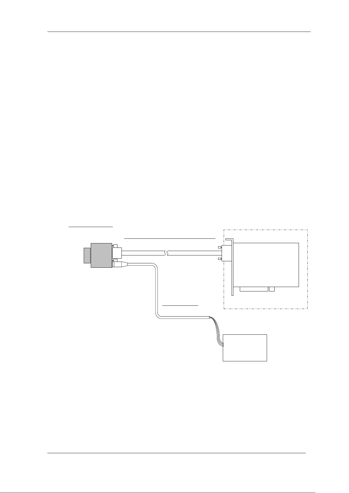
3.1 Camera Connection
(1) Camera Link cables shall be used to connect the camera unit with the frame
grabber board.
If you use asymmetric Camera Link cables, connect the camera with the
connector labeled as ”Camera side”.
(2) Connect with a power supply.
Use a power cable to connect the camera with the power source for the
camera. Insert the plug end of the cable into the camera. Attach the opposite
end (loose wires) to the power unit.
Other than the above, a personal computer, a frame grabber board, a
photographic lens, a photographic lens mount, a light source and an encoder
are necessary, depending on the situation。
Figure 3-1-1 Connections between Camera and Frame Grabber Board and Power Supply
There are two connectors available for the Camera Link Medium Configuration
board. Always check the frame grabber board specifications before making
connections.
UME-0021-03 SU2020/SU2025
Page 18
NED
18
Solios model
clock speed(MHz)
maximum cable length (m)
SOL 6M CL E*
(20~66MHz)
40
9.8
66
8.0
SOL 6M FC E*
(20~85MHz)
75
7.6
85
5.8
+12V Power Indicator
Power Connector
MDR26 Connector
CAMERA LINK BASE
MADE IN JAPAN
NIPPON ELECTRO SENSORY DEVICE CORP.
SCAN
<Note: Choosing the appropriate Camera Link cable length >
According to the Camera Link Specification, the maximum cable length is 10m. But
the maximum cable length to be able to transfer data depends on the type of cable
performance and clock speed. The actual maximum transmission distance becomes
less than 10m at faster clock speeds, though the transmission distance of 10m is
feasible at slower clock speeds.
The following table shows values being calculated in accordance with the Camera
Link Specification 2007.Version1.2., using a typical cable (14B26-SZLB-xxx-0LC from
3M) and frame grabber board (Solios from Matrox). Please choose the appropriate
Camera Link cable type and length for your application. We recommend you perform
a connection test in advance.
Table 3-1-1 calculated value of maximum cable length
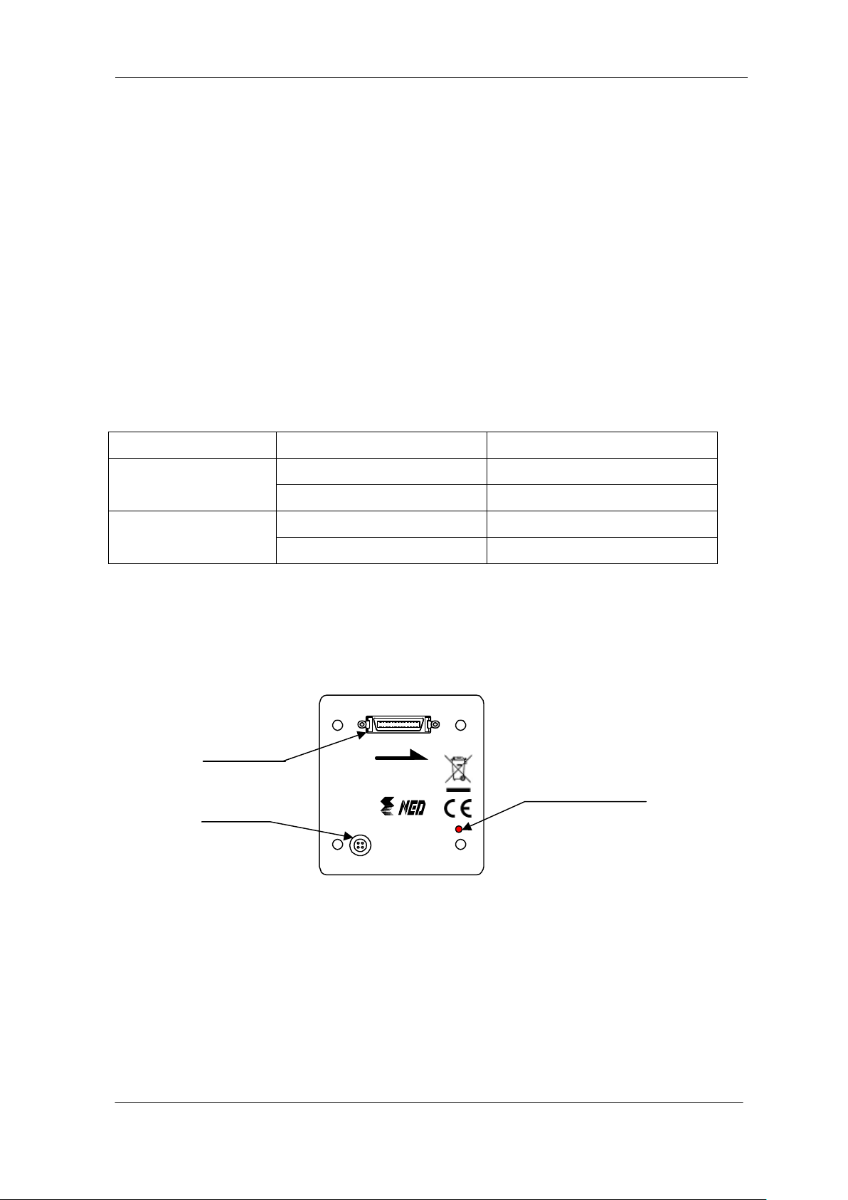
3.2 Input / Output Connectors and Indicator
The layout of input /output connecters and the indicator lamp are as follows.
Figure 3-2-1 Input/Output Connectors and Indicator
SU2020/SU2025 UME-0021-03
Page 19
NED
19
28 28
Frame Grabber BoardCamera
26-pin MDR Connector
CC1(control input)
Cable
SerTC
SerTFG
CK25MHz
Channel Link Bus
LVAL,FVAL
DVAL,SP
CD0~CD11
CC2
CC3
CC4
X1±
X0±
X2±
X3±
XClk±
100Ω
100Ω
100Ω
100Ω
100Ω
100Ω
100Ω
100Ω
100Ω
100Ω
100Ω
SerTFG±
SerTC±
CC1±
CC2±
CC3±
CC4±
26-pin MDR Connector
X1±
X0±
X2±
X3±
XClk±
SerTFG±
SerTC±
CC1±
CC2±
CC3±
CC4±
LVDS_DRIVER(NS)
DS90CR285MTD
equivalent
LVDS_DRIVER/
RECEIVER(NS)
DS90LV019TM
equivalent
LVDS_RECEIVER(NS)
DS90LV048AT
equivalent
LVDS_RECEIVER(NS)
DS90CR286MTD
recommended
LVDS_DRIVER/
RECEIVER(NS)
DS90LV019TM
recommended
LVDS_DRIVER(NS)
DS90LV047AT
recommended
+
-
100Ω
+
-
Driver Receiver
H or L
3.3 Connectors・Pin Assignments・Cables
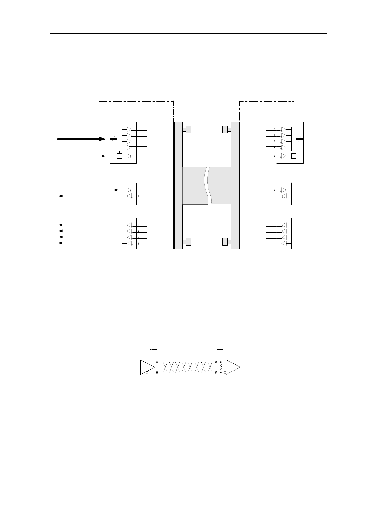
This camera uses the Base Configuration of Camera Link interface standards.
The figure shown below shows the interface for the camera and a typical
implementation for the frame grabber interface.
Set the LVDS, Channel Link receiver side to 100-ohm termination.
With the driver side of LVDS, even if not used, do not make it open but set the
logic to H or L.
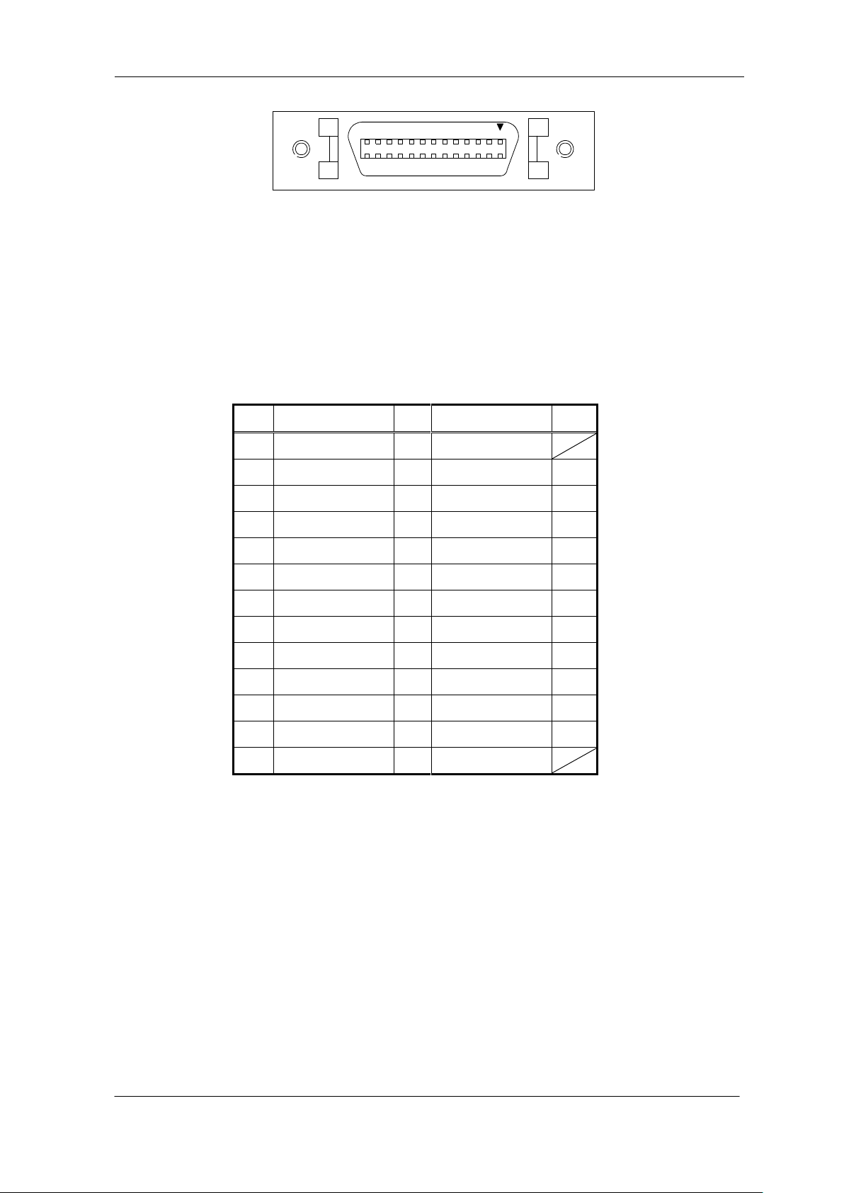
The camera has 26-pin MDR connectors for control signals of Camera Link, data
signals and serial communications. The camera also has a 4-pin HIROSE
connector for power supply.
UME-0021-03 SU2020/SU2025
Figure 3-3-1 Camera / Frame Grabber Interface
Figure 3-3-2 Circuit of LVDS
Page 20
NED
20
No
NAME
No
NAME
I/O
1
Inner Shield
14
Inner Shield
2 X0-
15
X0+
Out
3
X1-
16
X1+
Out
4
X2-
17
X2+
Out
5
Xclk-
18
Xclk+
Out
6
X3-
19
X3+
Out
7
SerTC+
20
SerTC-
In 8 SerTFG-
21
SerTFG+
Out
9
CC1-
22
CC1+
In
10
CC2+
23
CC2-
In
11
CC3-
24
CC3+
In
12
CC4+
25
CC4-
In
13
Inner Shield
26
Inner Shield
1142153
16
1124122513
26
Figure 3-3-3 Camera Link Connector
Half pitch (miniature half ribbon) shape
Locking screw (UNC #4-40) type
Table 3-3-1 Camera Link Connector (26-pin MDR Connector) pin assignments
SU2020/SU2025 UME-0021-03
Page 21
NED
21
No
NAME
Color of Cable
1
12 V
White
2
12 V
Red
3
GND
Green
4
GND
Black
1
2
4
3
Explanation of Signals
Inner Shield : Shield cable (GND)
X0+,X0-…X2+,X2- : Data output (Channel Link)
Xclk+,Xclk- : Clock output for above data output synchronization (Channel Link)
SerTC+, SerTC- : Serial data input (LVDS)
SerTFG+, SerTFG- : Serial data output (LVDS)
CC1+,CC1- : External synchronous signal input (LVDS)
*When using External Trigger
CC2+,CC2- : Not in use (LVDS)
CC3+,CC3- : Not in use (LVDS)
CC4+,CC4- : Not in use (LVDS)
Camera Link compatible cable
14B26 - SZLB - xxx - 0LC by 3M (or equivalent)
To avoid uncoupling of cable connectors during power on, make sure to clamp
them with locking screws.
Do not unplug the cable while power is being supplied to the camera.
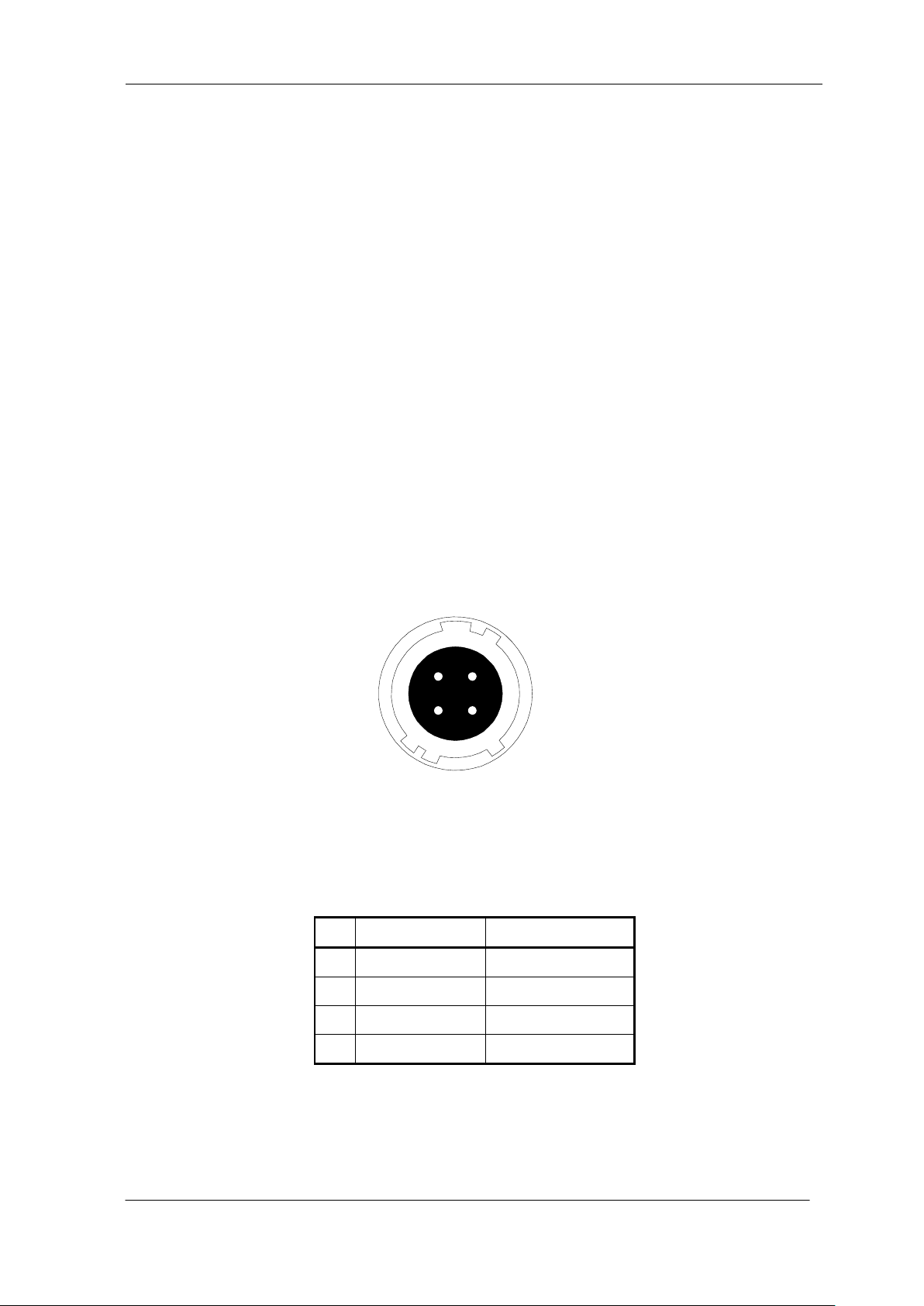
The pin assignment of the power supply connector is shown below.
Figure 3-3-4 Power Supply Connector (HIROSE : HR10G -7R- 4PB)
Round shape push-pull lock type
Table 3-3-2 Pin Assignment of Power Supply Connector
UME-0021-03 SU2020/SU2025
Page 22

NED
22
3.4 Power Supply
The camera requires a single power supply (DC+12V).
When selecting a power source, choose one with the capacity to allow for
inrush current. (15W or more recommended)
Insert the cable plug securely until it locks into position. This is to prevent
the connector from coming loose during power transmission.
Compatible Cable (Compatible plug): DGPS -10 (HIROSE : HR10A -7P - 4S)
Power supply voltage: DC+12V (+/-5%)
Consumption Current (rated): DC+12V : 270mA
The LED lamp illuminates when DC +12V power is being supplied to the camera.
If the lamp fails to illuminate even after power is supplied, turn OFF power
immediately. Inspect wiring. Check the voltage and capacity of the supplied
power source.
SU2020/SU2025 UME-0021-03
Page 23

NED
23
4 Camera Control
The camera can be controlled through serial communication. Two methods can
be used to change the camera’s parameters. The first approach is to change
parameters using NCCtrl02 (Camera control software). (See “8 NCCtrl”.) Or you
can also change the parameters directly from your application by using binary
read/write commands to set values in the camera register.
The camera can be used without the serial interface after it has been set up
correctly.
4.1 Flow of Camera Control
4.1.1 Command Overview
The serial interface uses a simple ASCII-based command.
Communication begins when the computer sends control commands to the camera.
The camera receives and interprets the computer commands and then executes
control operation accordingly.
Transmission ends when the camera returns the analyzed results of control
commands to the computer.
Always allow the previous transmission to end before starting the next transmission.
(Only one command can be sent per transmission.)
4.1.2 Command Format (PC to Camera Transmission)
Format C [VAL] CR
CMD: Control text (1 Bytes)
VAL: Setting value (decimal, 1 Bytes x maximum 3 digits)
※When there is no set value, it is unnecessary.
CR: Carriage Return (0x0D)
<Example>
t 0 CR
UME-0021-03 SU2020/SU2025
Page 24
NED
24
Camera Response
Meaning
OK
Camera executed command
CMD ERR!
Command is not valid
CMD OVR ERR!
Command text line is too long
VAL ERR!
Parameter accepted was outside of specified
MEM ERR!
Memory error
4.1.3 Reply Format (Camera to PC Transmission)
Format 1 > R CR
Format 2 > [MEM] CR
Format 3 > [SB] CR
Format 4 EOT
> : Results start text (03E)
R: Camera receive command analyzed results
[SB] : Camera receive command send back
[MEM] : Memory data readout value
CR: Separated text (00D)
EOT: Send command all text End text (004)
<Example>
>OK CR >r0 CR EOT
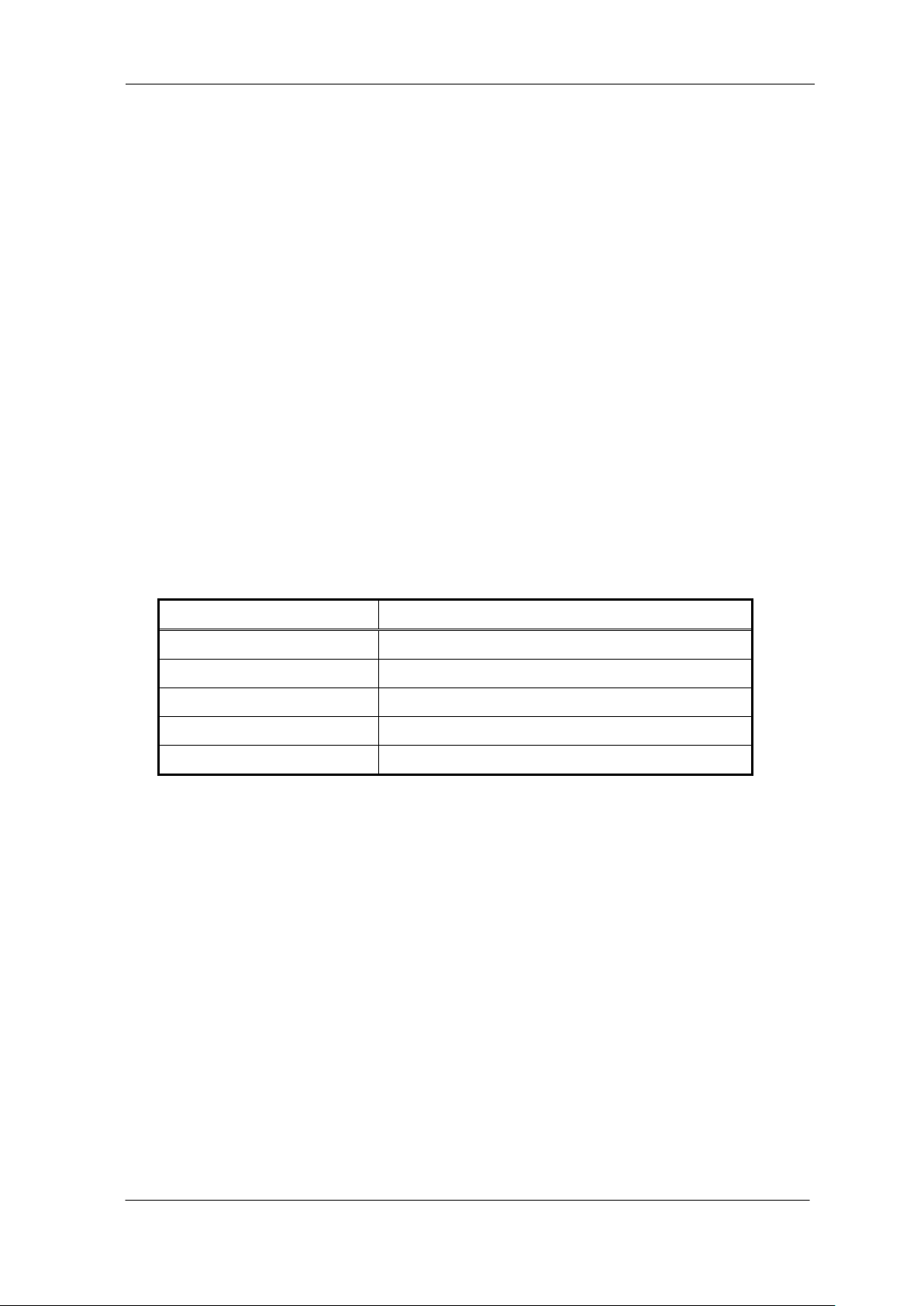
Table 4-1-3-1 Error Messages
Built-in memory
Built-in memory using the EEPROM, can be rewritten.
Endurance is built-in memory depending on the conditions of use, more than
100,000 times (typ).
SU2020/SU2025 UME-0021-03
Page 25
NED
25
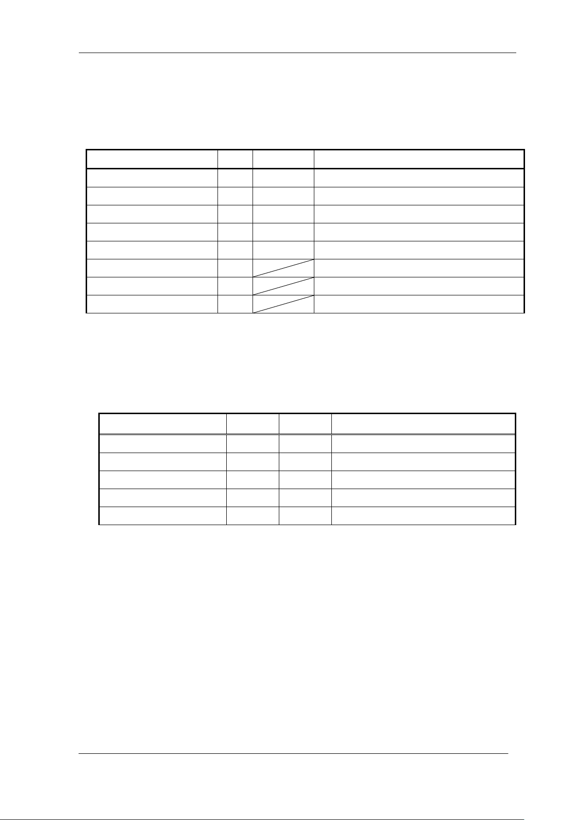
Control Item
CMD
VAL
Control Description
Gain g 0~688
Setting Gain
CDS Gain
a
0~4
Setting CDS Gain
Offset
o
0~19
Setting Digital Offset
Video output switching
v
0、1、2
8 bit / 10 bit / 12 bit
Trigger mode switching
t
0、1
Free run / ExTrg
Memory Save
w
Store present setup data in memory
Memory Load
l
Readout setup data in memory
Memory Initializing
z
Reset to factory settings ※see 4.1.5
Control Item
CMD
VAL
Control Description
Gain g 0
0dB
CDS Gain
a
4
-3dB
Offset o 4
4±3 Level when the light shielding
Video output switching
v
0
8 bit
Trigger mode switching
t
0
Free Run
4.1.4 Camera Control Commands
The table below shows the list of Camera Control Commands.
Table 4-1-4-1 List of Camera Control Commands
4.1.5 Memory Setup Values (Factory Settings)
The memory setup values (factory settings) are shown below.
Table 4-1-5-1 Memory Setup Values (Factory Settings)
UME-0021-03 SU2020/SU2025
Page 26

NED
26
4.2 Details on Commands
4.2.1 Setting Gain
Sets gain in between 0 ~ 688.
Format C VAL CR
CMD g
VAL 0 - 688
<Example>
g5 CR (Setting digital gain 0.16dB)
>OK
>g5
4.2.2 Setting CDS Gain
Sets CDS gain in between 0 - 4
Format 2 C VAL CR
CMD a
VAL 0 - 4
<Example>
a3 CR (Setting CDS gain 9dB)
>OK
>a3
4.2.3 Setting Offset
Sets offset in between 0 - 19
Format CMD VAL CR
CMD o
VAL 0 - 19
<Example>
o5 CR (Setting offset 5/8bit・20/10bit・80/12bit)
>OK
>o5
SU2020/SU2025 UME-0021-03
Page 27

NED
27
4.2.4 Switching video output
Sets the exposure mode.
Format CMD VAL CR
CMD v
VAL 0、1、2(Switching output data 8bit/10bit/12bit)
<Example>
v0 CR CR (Setting output data 8bit)
>OK
>v0
4.2.5 Switching trigger mode
Switch trigger mode.
Format CMD VAL CR
CMD t
VAL1 0,1(Switching trigger mode FreeRun/ExTrg)
<Example>
t0 CR (Setting Free Run mode)
>OK
>t0
4.2.6 Memory Save
Stores current camera settings in the flash memory.
Format CMD CR
CMD w
<Example>
wCR
>OK
>w
4.2.7 Memory Load
Reads out the camera settings from the flash memory.
Format CMD CR
CMD l
<Example>
lCR
>OK
>l0
UME-0021-03 SU2020/SU2025
Page 28

NED
28
4.2.8 Memory Initializing (Initializing Camera Settings)
Reset the flash memory to the factory default.
Format CMD CR
CMD z
<Example>
zCR
>OK
>z0
4.3 Startup
After turning on, the camera runs a startup procedure before it starts getting
images and outputting data.
The startup procedure is as follows.
(1) The camera initializes the hardware.
(2) Reads out the latest camera settings from the flash memory. (User settings if
any or factory default settings)
(3) Sets up the camera with the setting values from the flash memory.
After this sequence, the camera is ready to get images and output data.
4.4 Saving and Loading Camera Settings
The camera setting data is saved in the internal memory (flash memory) and is
loaded from the memory when turning on the power supply or loading (sending the
“ l ” command).
The number of times the flash memory can be rewritten will vary depending
on actual operational conditions. After turning on the power supply, the camera
always checks the memory status. If the data is not within the designated range
due to a malfunction or other type of trouble, the memory will be automatically
rewritten with the factory settings.
If disconnecting camera power while rewriting the memory, all data saved in
the memory will be deleted.
As it takes several seconds to rewrite the memory, do not disconnect the power
supply before receiving the response from the camera.
Commands for rewriting the memory are as follows.
Reset to factory settings(z)
Store present data in memory(w)
SU2020/SU2025 UME-0021-03
Page 29
NED
29
Camera operation mode
(Exposure mode)
Control input
(from frame grabber board)
Free Run (Programmable time setting)
(Factory Setting)
Not in use
Ext Trg (External trigger)
External trigger (CC1) is required
Parameter Items
Setup Value
Communication Speed (Baud rate)
9600bps
Data Length
8bit
Parity Bit
None
Stop bit
1bit
Flow Control
None
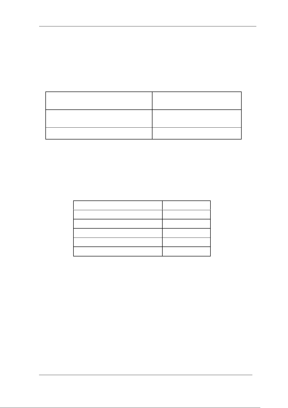
When changing the factory setting exposure mode, be sure to send the control
input signal (CC1) from the frame grabber board. If you do not send CC1 or
sending control input signals are out of the designated range, you cannot get
images and can not change the setting. See 4.7.1 and 4.7.2.
Table 4-4-1 Camera Operation Mode and Control Input
4.5 Serial Communication Settings
Serial communication is performed through the Camera Link Interface
The table below shows the serial communication settings.
Table 4-5-1 Serial Communication Settings
UME-0021-03 SU2020/SU2025
Page 30
NED
30
LSB
MSB
12bit
8bit
LSB
MSB
bit9
bit8
bit7
bit6
bit5
bit4
bit3
bit2
bit1
bit0
8bit(標準)
ADC
10bit
bit11
bit10
10bit
LSB
MSB
bit9
bit8
bit7
bit6
bit5
bit4
bit3
bit2
bit1
bit0
ADC
bit11
bit10
12bit
bit9
bit8
bit7
bit6
bit5
bit4
bit3
bit2
bit1
bit0
ADC
bit11
bit10
invalid 1 2046 20472 3 2048invalidinvalid invalidinvalid invalidinvalid invalid
XClk
(20M
25M)
VIDEO
DVAL
LVAL
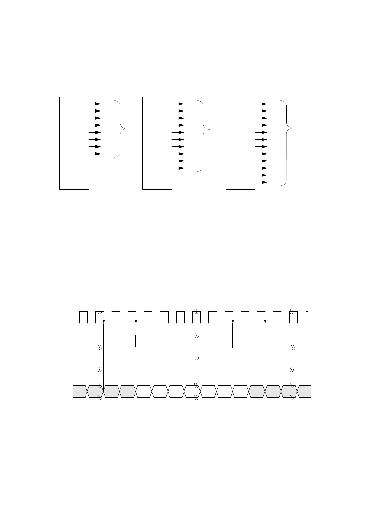
4.6 Video Output Format
The camera outputs 8-bit or 10-bit digital data.
Figure 4-6-1 Pin Assignments of Digital Data
The A/D converter of the camera has a 10-bit resolution. For 8-bit output, the
upper 8-bit signal can be output as a video data.
The video output phase is shown below.
FVAL = 0 (low level) fixed
DVAL= 0 (low level) fixed
SU2020/SU2025 UME-0021-03
Figure 4-6-2 Video Output Phase
Page 31
NED
31
valid data 2048 piexlesinvalid data(0) invalid data(0)
2052CK
XClk
(20M
25M)
DVAL
VIDEO
2048CK
LVAL
152CK 152CK
2CK
2CK
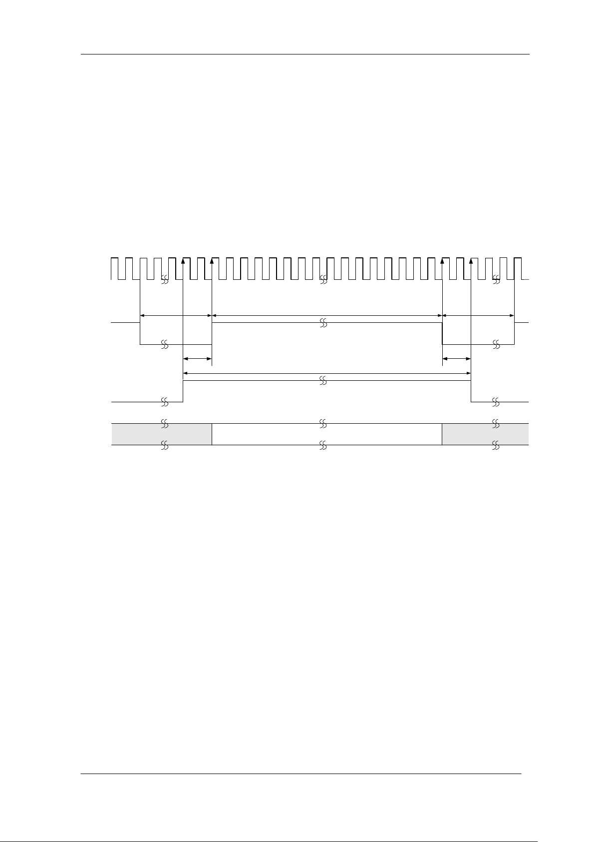
4.7 Exposure Mode and Timing Chart
The camera has three exposure modes. The overview of each mode and the
timing are as follows.
4.7.1 Free Run Mode
In free-run exposure mode, the camera generates its own internal control signal
based on two programmable parameters, exposure time and readout time. Timing
relationship of each signal is as follows.
Figure 4-7-1-1 Timing Chart
UME-0021-03 SU2020/SU2025
Page 32
NED
32
valid data 2048 pixelesinvalid data(0) invalid data(0)
≧2CK
≧2200CK
2052CK
XClk
(20M
25M)
DVAL
VIDEO
CC1
2048CK
LVAL
79CK
≧1CK
2CK
2CK
Dd
Fs
Se
Amount of Incident
Light (lx・s)
Output
Fs : Saturation Output
Dd : Dark Current
Se : Saturation Exposure
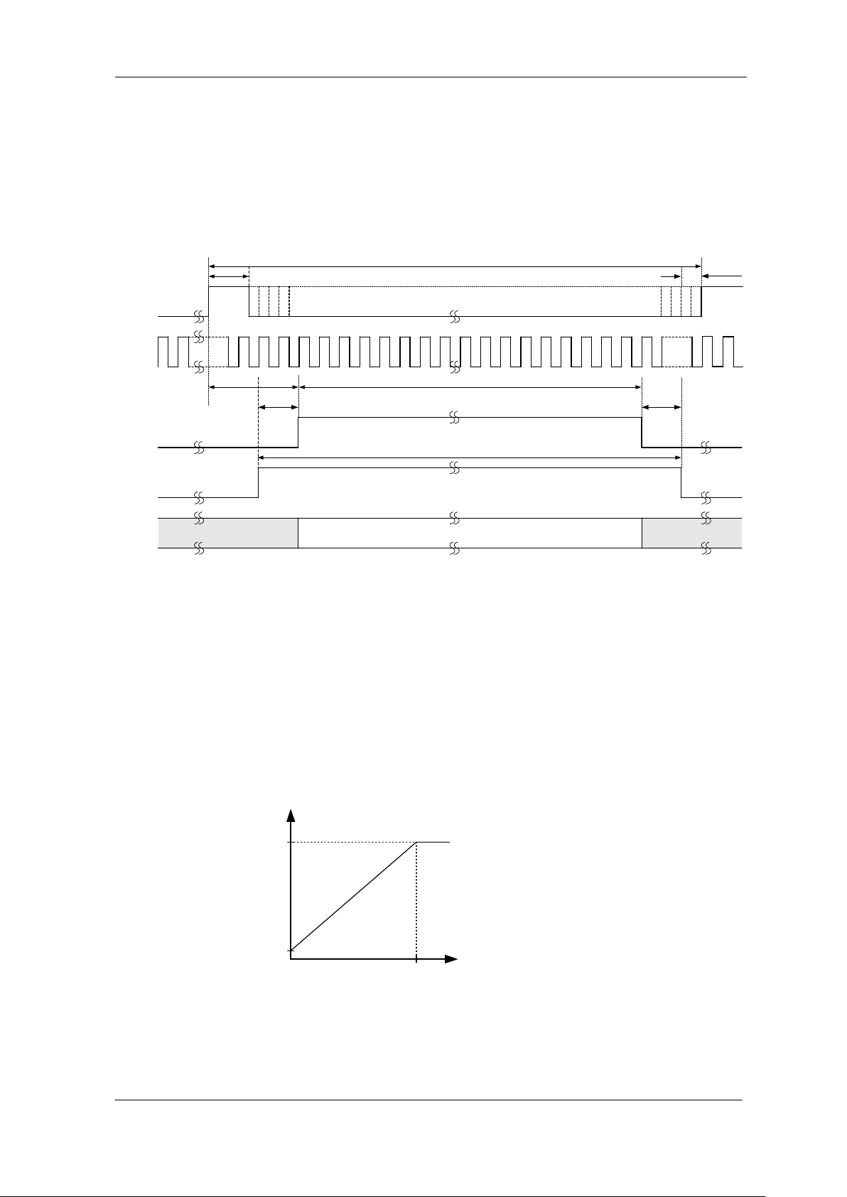
4.7.2 External Trigger (ExTrg) Exposure Mode
In external trigger exposure mode (Trigger Edge), the exposure time is determined
by the setting made through serial communication. Each exposure starts with the
rising edge and the line period is determined by the time from rising edge to rising
edge of the trigger pulse. Timing relationship of each signal is as follows.
Figure 4-7-2-1 External Trigger (Trigger Edge) Exposure Mode
4.8 Setting Offset
In the figure below, the horizontal axis indicates the amount of incident light and
the vertical axis indicates the output. Fs shows the output at saturation. Dd shows
the output at darkness. (Both Fs and Dd are digital.) Se shows the saturation
current, or the amount of exposure when the output saturates.
SU2020/SU2025 UME-0021-03
Figure 4-8-1 Saturation Exposure and Dark Current Output
Page 33
NED
33
Output
DF : Offset Value
DF
Amount of
Incident Light
(lx・s)
Fs
Fs : Saturation Output
Gain a
Amount of Incident
Light (lx・s)
(a<b<c)
Gain b
Gain c
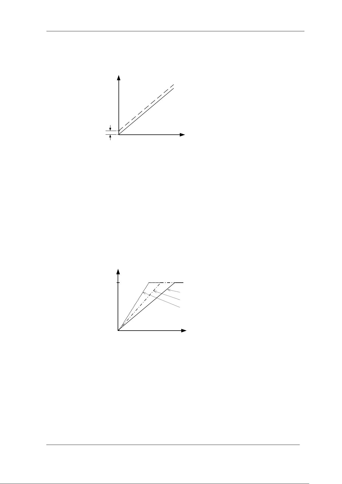
By setting the offset, you can set the Y-intercept arbitrarily. DF shows the digital
offset value. The gradient of the line does not change.
Figure 4-8-2 Offset Adjustment
Adjust amount of offset in accordance with the requirements of your camera
system.
4.9 Setting Gain
The camera can adjust the analog gain (x1 to x11.2 in 21 steps) and the digital
gain. As shown in the figure below, increasing the gain setting increases the
gradient of the camera’s response curve and results in a higher camera output for
a given amount of light. Analog gain can be changed by sending the ”gax”
command. Digital gain can be changed by sending the “gdx” command.
Figure 4-9-1 PGA Gain Adjustment
Gain and noise values are proportionally related.
Adjust the amount of gain in accordance with the requirements of your camera
system.
UME-0021-03 SU2020/SU2025
Page 34
NED
34
No
NAME
Color of Cable
1
12 -15V
White
2
12 -15V
Red
3
GND
Green
4
GND
Black
1
2
4
3
Camera side
Frame grabber side
5 Confirming Camera Settings
5.1 Before Power-on
Please check the exterior for any damages that may have been transportation or
handling etc.
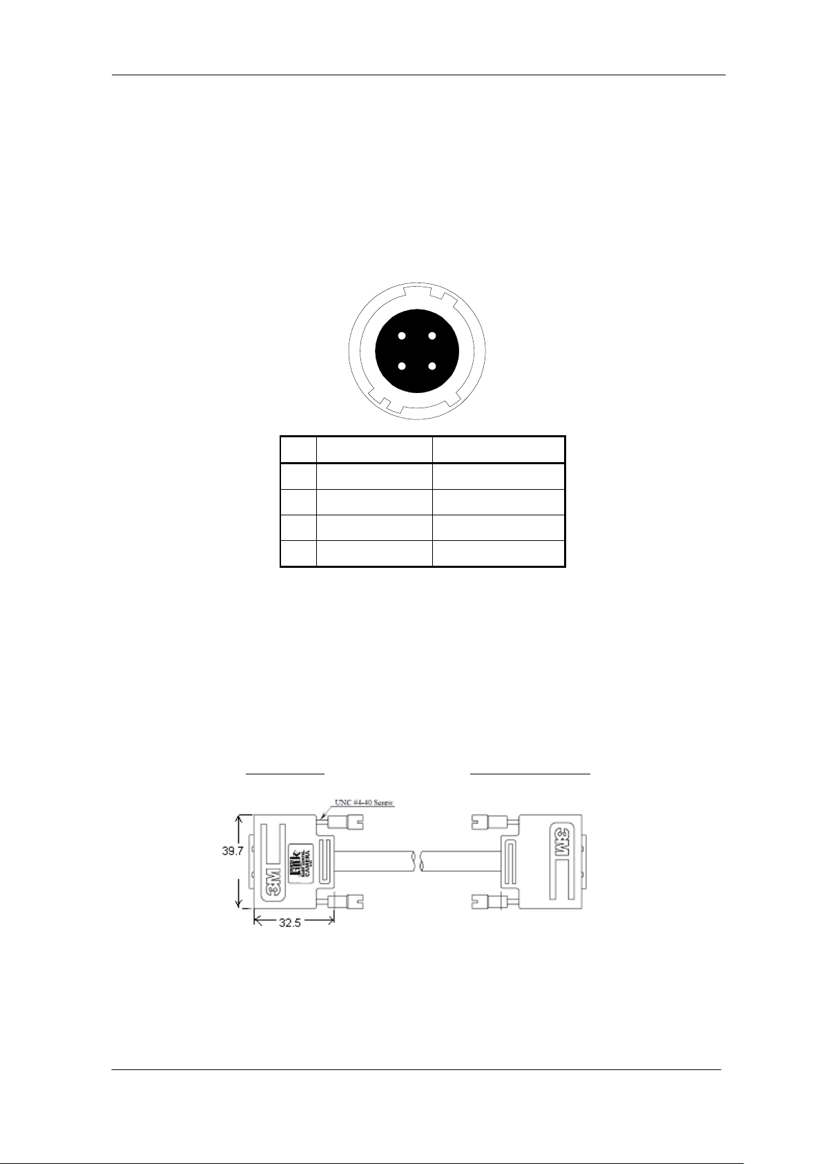
(1) Confirm the pin assignment of the power cable.
Figure 5-1-1 Pin Assignment of Power Cable
(2) Confirm the direction and the channel of the cables. Some Camera Link
cables are directional.
If one of the connectors says “Camera side”, connect this to the camera.
Figure 5-1-2 Connection Direction of Camera Cable
SU2020/SU2025 UME-0021-03
Page 35
NED
35
CHANNEL #0
CHANNEL #1
CAMERA LINK BASE
MADE IN JAPAN
NIPPON ELECTRO SENSORY DEVICE CORP.
SCAN
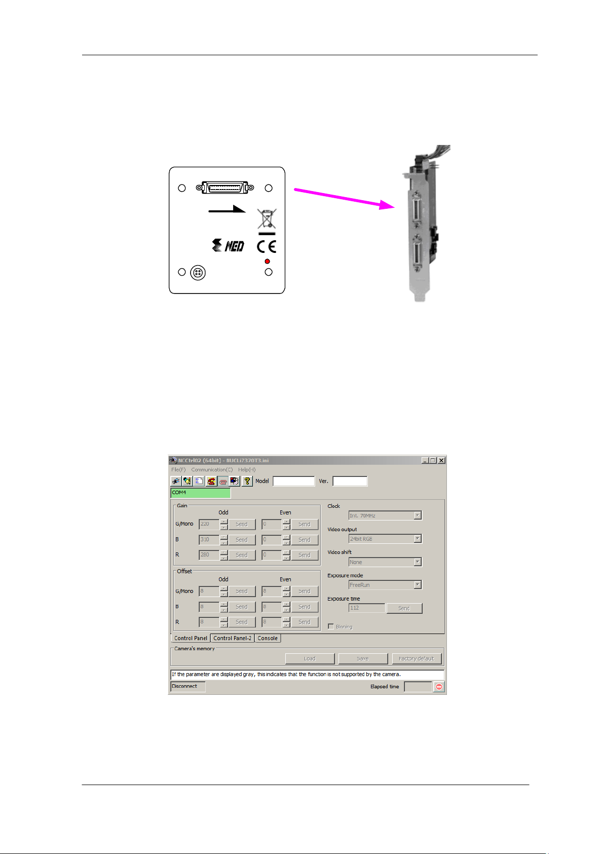
The connection channel of in the case of using a “Solios” board:
CL1 = CHANNEL #0
Figure 5-1-3 Channel of Camera Link Cables
5.2 After Power-on
(1) Confirm sent and received commands using the camera control utility. Launch
NCCtrl02, set COM port and connect. Click “Memory Dump” and wait for the
response.
UME-0021-03 SU2020/SU2025
Figure 5-2-1 Confirmation of Connection
Page 36
NED
36
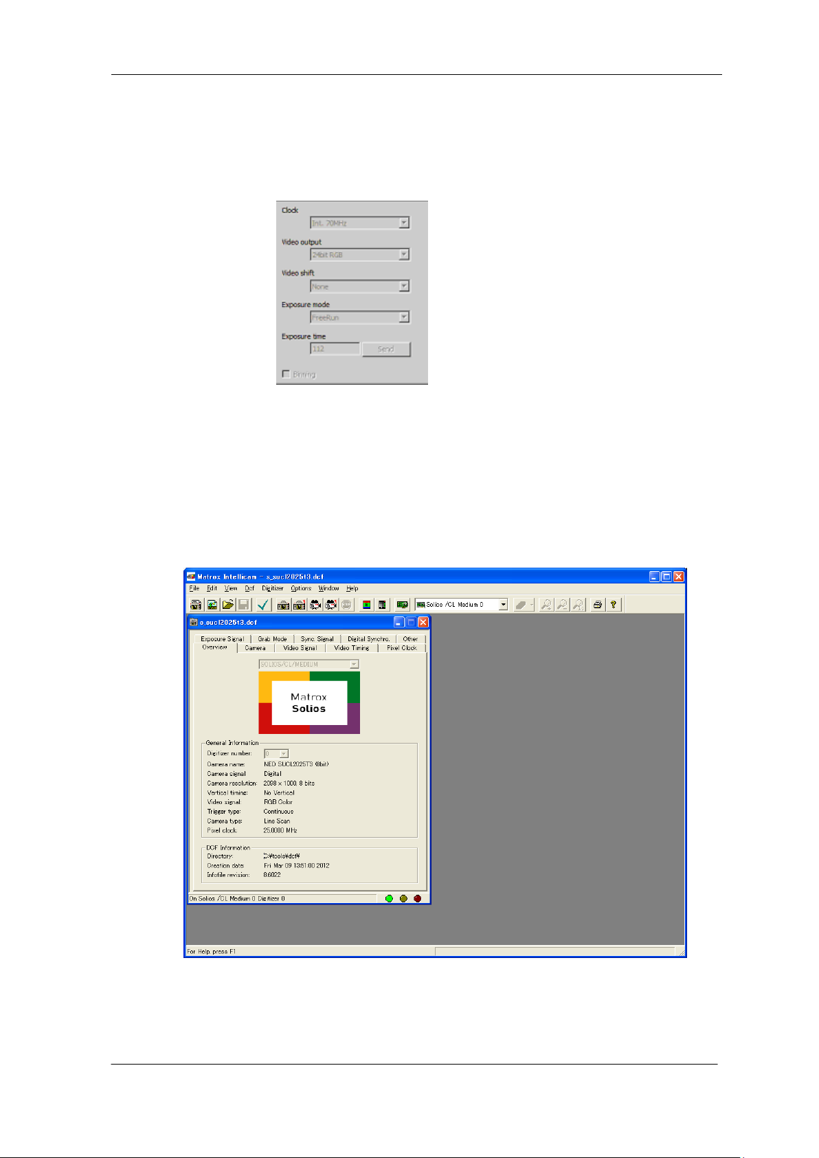
(2) Set a trigger mode and a video output mode with the camera control utility.
Trigger mode = Free run
Video output mode =8bit
Figure 5-2-2 Exposure Mode and Video Output Mode
If you have your own application to check the images, select suitable settings.
(3) Capture images using a camera interface board utility. In the case of Matrox’s
Solios, it is convenient to use Intellicam.
Figure 5-2-3 Solios Window
SU2020/SU2025 UME-0021-03
Page 37

NED
37
5.3 During Operation
(1) Does an acquisition time out error occur?
<Cause>
<1> Captured images are too large.
If there are many filtering processes, the assignments to the driver may be
insufficient.
<2> The cable is detached from the connector
Ensure that the power cable and Camera Link cables are connected to the
camera firmly.
<3> Camera Link cables are susceptible to noise when the cables are laid near a
light source inverter line or a power line. The personal computer in use may be
freeze and need to be reset.
(2) Are there dark lines in the direction of vertical scanning on the image?
<Cause>
<1> Dust on the sensor window
Dust may get onto the sensor window from the inside or the outside of the
camera. Remove the dust with air or a lens cleaner.
UME-0021-03 SU2020/SU2025
Page 38

NED
38
6 Sensor Handling Instructions
6.1 Electrostatic Discharge and the Sensor
CMOS sensors are susceptible to damage from electrostatic discharge and can
deteriorate as a result. Take care when handing the sensor.
6.2 Protecting Against Dust, Oil and Scratches
The CMOS sensor window is part of the optical path and should be handled like
other optical components with care. If you use the camera in a dusty area, prepare
a dust-proof enclosure. Dust can obscure pixels, producing dark lines on the
image.
6.3 Cleaning the Sensor Window
Dust: Can usually be removed by blowing the window surface using a
compressed air blower.
Oil: Wipe the window with a lint-free cloth wiper moistened with ethyl alcohol
carefully and slowly.
When there is dust or smudges on the sensor window, it appears in the same
way as noise on the image. Please remove it appropriately.
SU2020/SU2025 UME-0021-03
Page 39
NED
39
The indicator is glowing.
The camera has the correct connections
with the power source and the frame
grabber.
Use a power source that meets
the specifications.
The camera has the correct
connection with the frame grabber.
The camera may be out of
order. Please contact us
for service.
After power on, the power source meets the
specified voltage.
The capacity of the power
source is sufficient
Connect the camera and the frame
grabber board with camera cables.
After being powered on, set up the
frame grabber board suitably.
The sample software program is used to control
the camera.
The sample software program is used to
control the camera and is communicating
with the camera successfully.
Confirm the communication software, the control
protocol for the camera and commands.
The power source meets the specified voltage.
The frame grabber board is
powered on and set up.
Yes
The frame grabber
is communicating
with the camera
successfully.
Yes
Yes
No
No
Yes
No
No
No
Yes
No
No
No
No
No
Yes
Yes
Yes
Yes
To next page
B
To next page
A
To next page
B
7 Troubleshooting
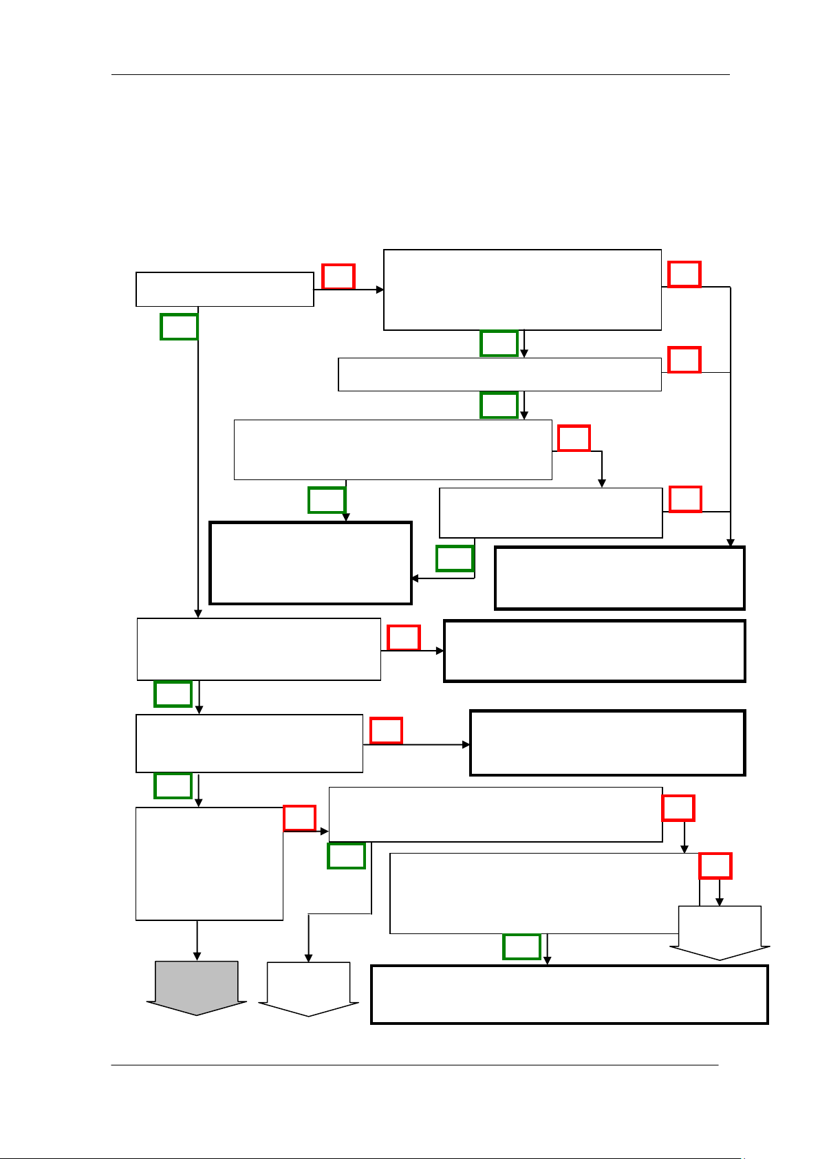
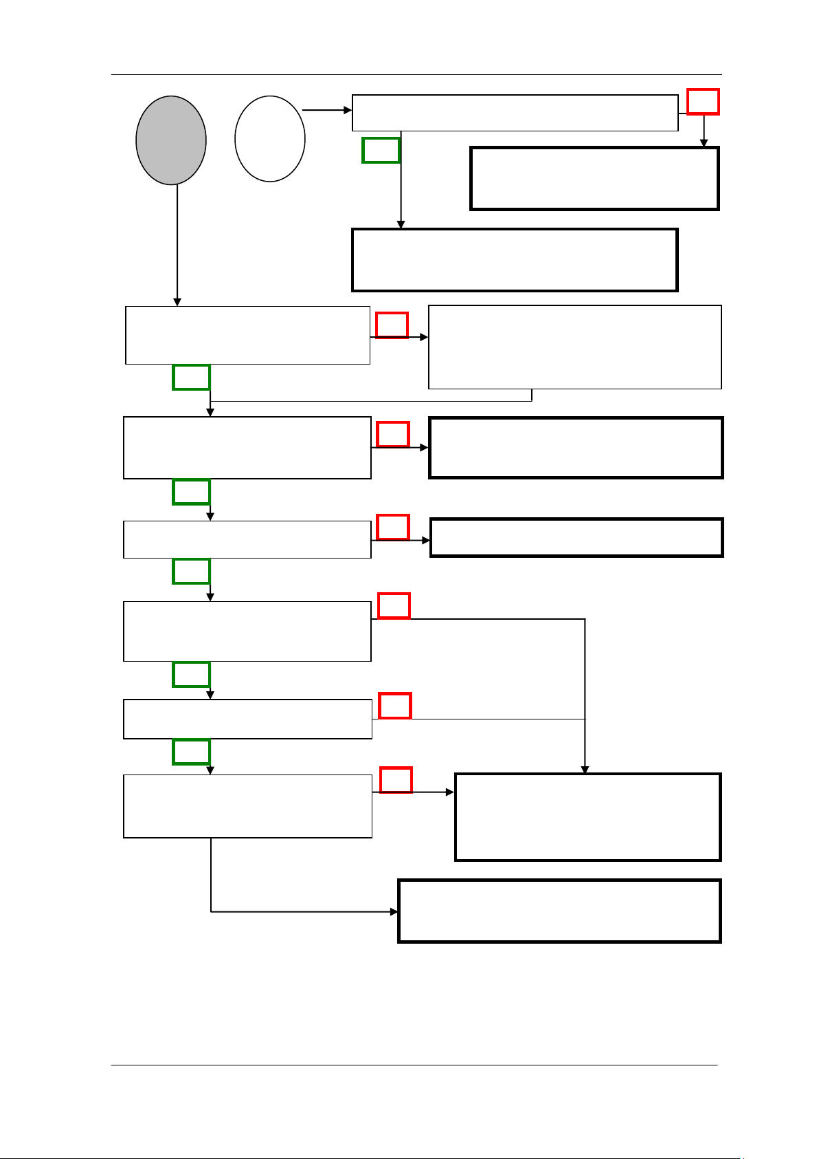
The following pages contain several troubleshooting charts that can help you find
the cause of problems users sometimes encounter.
7.1 No Image
UME-0021-03 SU2020/SU2025
Page 40
NED
40
The capture software program is
custom made.
With the sample software program
provided, no image is captured.
The communication port is set correctly.
Nothing blocks off the light.
If a lens cap is attached, take it off.
The amount of illumination is
enough.
Check the light source. If the
images are too dark, try to increase
the light intensity, and vice versa.
No image at the full aperture.
The optical axes of the camera and
the image sensor are aligned.
Check the compatibility between the
camera and the frame grabber board.
The capture software program is provided
with the board as a sample program.
Set the communication port
correctly.
The camera may be out of order. Please
contact us for service.
The camera may be out of order. Please
contact us for service.
No
Yes
No
Yes
No
No
Yes
Yes
Yes
Yes
No
No
No
B
A
SU2020/SU2025 UME-0021-03
Page 41
NED
41
Noise is present from
the beginning.
A servomotor or a
magnetic valve is placed
near the camera.
The camera has been used for 3 or
more years, or the ambient
temperature is higher than room
temperature.
There are some consumable parts
in the camera. Please contact us
for service.
The power supply has been used for
3 or more years, or the ambient
temperature is higher than room
temperature.
Check the deterioration of the
power supply.
The camera, the camera cables and
the power source cable are in
swinging motion.
Check the deterioration of the
camera cables and the power
supply cable.
The camera may be out of order.
Please contact us for service.
Turning on a servomotor
or a magnetic valve
generates noise.
Prevent the noise
source from disturbing
the camera cables and
the power cable.
Yes
No
Yes
No
No
No
Yes
Yes
Yes
No
No
Yes
To next page
C
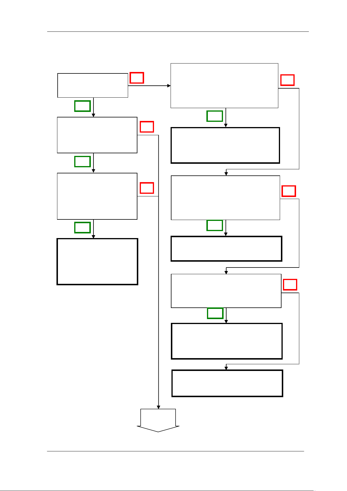
7.2 Noise on Image
UME-0021-03 SU2020/SU2025
Page 42
NED
42
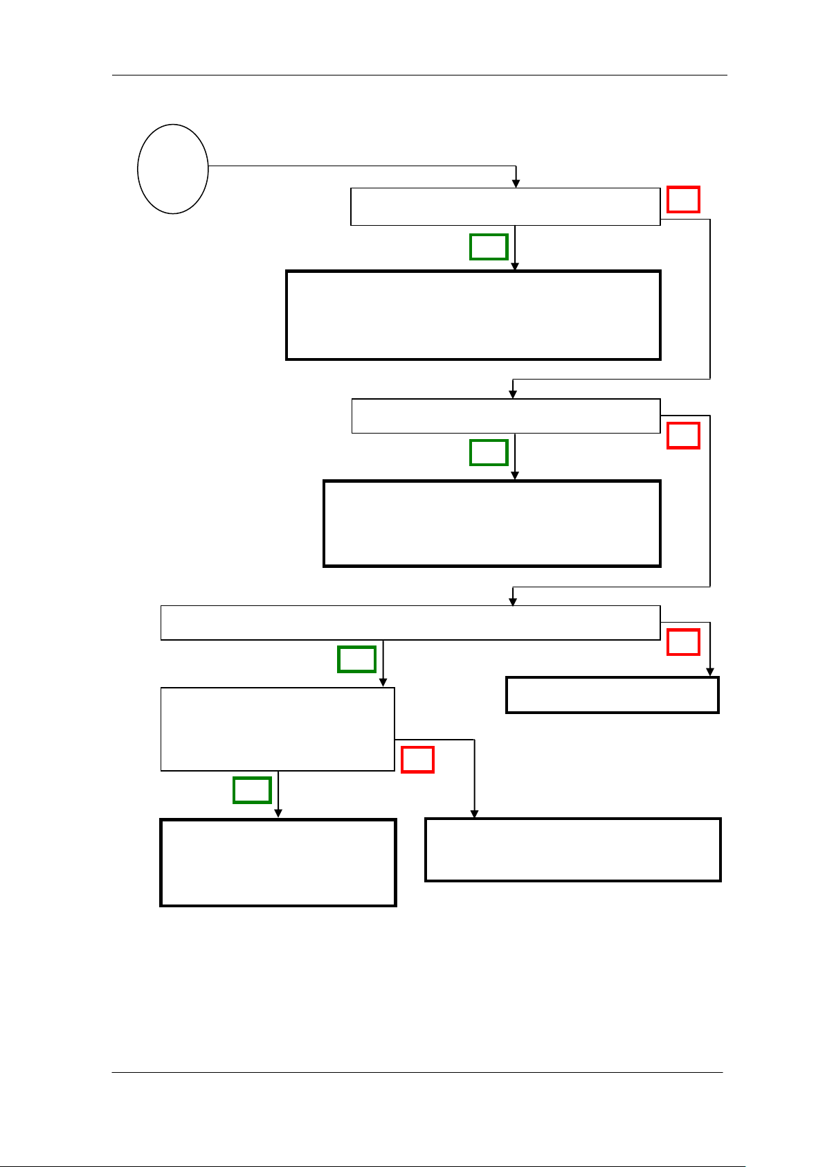
Cables are asymmetric e.g. thin cables.
Only one of the connectors of an asymmetric
camera cable can be connected with the camera.
(Labeled as “Camera side”)
The camera cables are too long.
Use camera cables in accordance with the
transmission rate. The cables should not be
too long in order to avoid noise disturbance.
The power source has no fluctuation in voltage and is not deteriorated.
Use a stable power supply.
The camera may be out of order. Please
contact us for service.
When the camera gain is on a
high level, bright spots occur
without incident light.
Secondary radiation (rays)
could cause bright spots, but
this is not a malfunction.
C
No
Yes
Yes
No
No
Yes
Yes
No
SU2020/SU2025 UME-0021-03
Page 43
NED
43
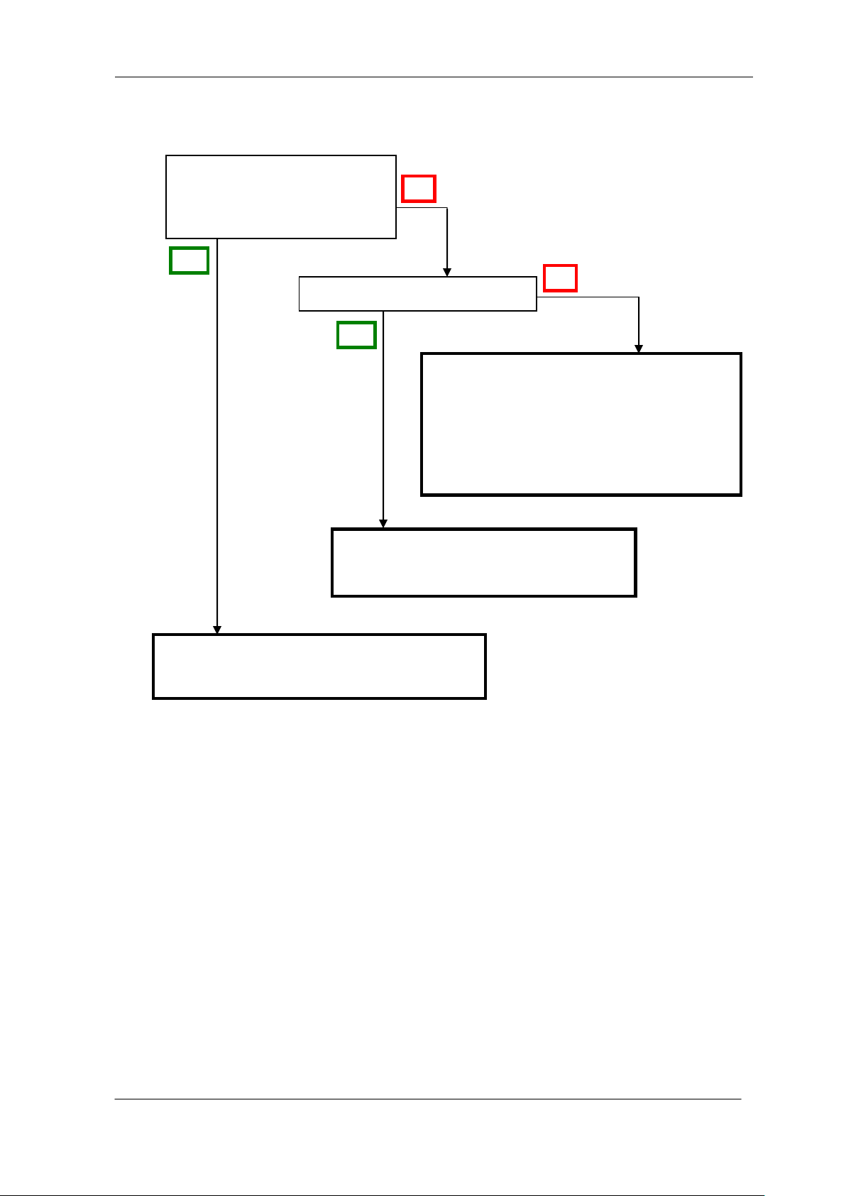
The camera is too hot to touch.
The consumption current of the
power supply is larger than the
rating.
The camera will become hotter than the
ambient temperature while in operation
because of self-heating. Allow sufficient
air circulation around the camera to give
it a longer life.
Keep the ambient temperature within
the range the specifications specify.
The camera may be out of order. Please
contact us for service.
Yes
No
No
Yes
7.3 Camera becomes hot
UME-0021-03 SU2020/SU2025
Page 44
NED
44
1
9
8
7
6
GND
5
4
TxD
3
RxD
2
1
9
8
7
6
GND
5
4
TxD
3
RxD
2
Dsub9s Dsub9s
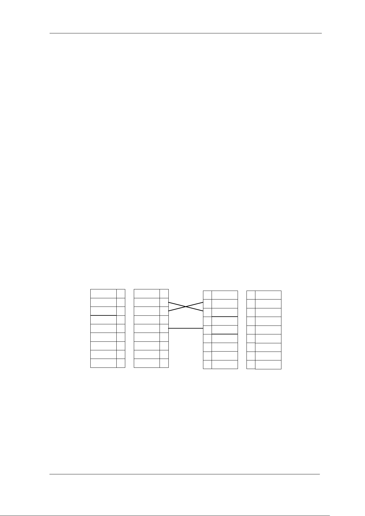
RS232C cross cable
1
9
8
7
6
GND
5
4
TxD
3
RxD
2
Dsub9p
Camera side
1
9
8
7
6
GND
5
4
TxD
3
RxD
2
Dsub9p
PC side
8 NCCtrl
8.1 Overview
NCCtrl02 is software designed for line scan cameras that support the NED camera control
protocol (NCCP). This software enables you to remotely control line scan cameras from a PC.
The following interface connections are available:
1) COM port (RS232C)
2) Camera Link
8.2 System Requirements
PC: PC/AT compatible
OS: Microsoft Windows series (9x / NT / 2000 / XP)
Free disk space: 1 MB – 2 MB
(The required size may vary depending on the number of camera setting files)
The following system environment is required for the respective interfaces.
For COM port (RS232C) connection:
1) COM port that is compatible with the hardware and OS
2) RS232C cross cable (Dsub9s – Dsub9s)
For Camera Link connection:
1) Camera Link compatible frame grabber board and device driver must be installed.
The DLL file for Camera Link API provided by the frame grabber manufacturer must be
2) Camera Link compatible cable
SU2020/SU2025 UME-0021-03
included. For details, ask the frame grabber manufacturer.
Page 45
NED
45
8.3 Install
Copy the NCCtrl02 folder from the media (CD-ROM, etc) provided to your hard disk.
8.4 Uninstall
1) Delete NCCtrl02 folder and all data files that included in that folder.
8.5 Operation
8.5.1 General description
UME-0021-03 SU2020/SU2025
Page 46
NED
46
A B C D E F G
8.5.2 Starting NCCtrl
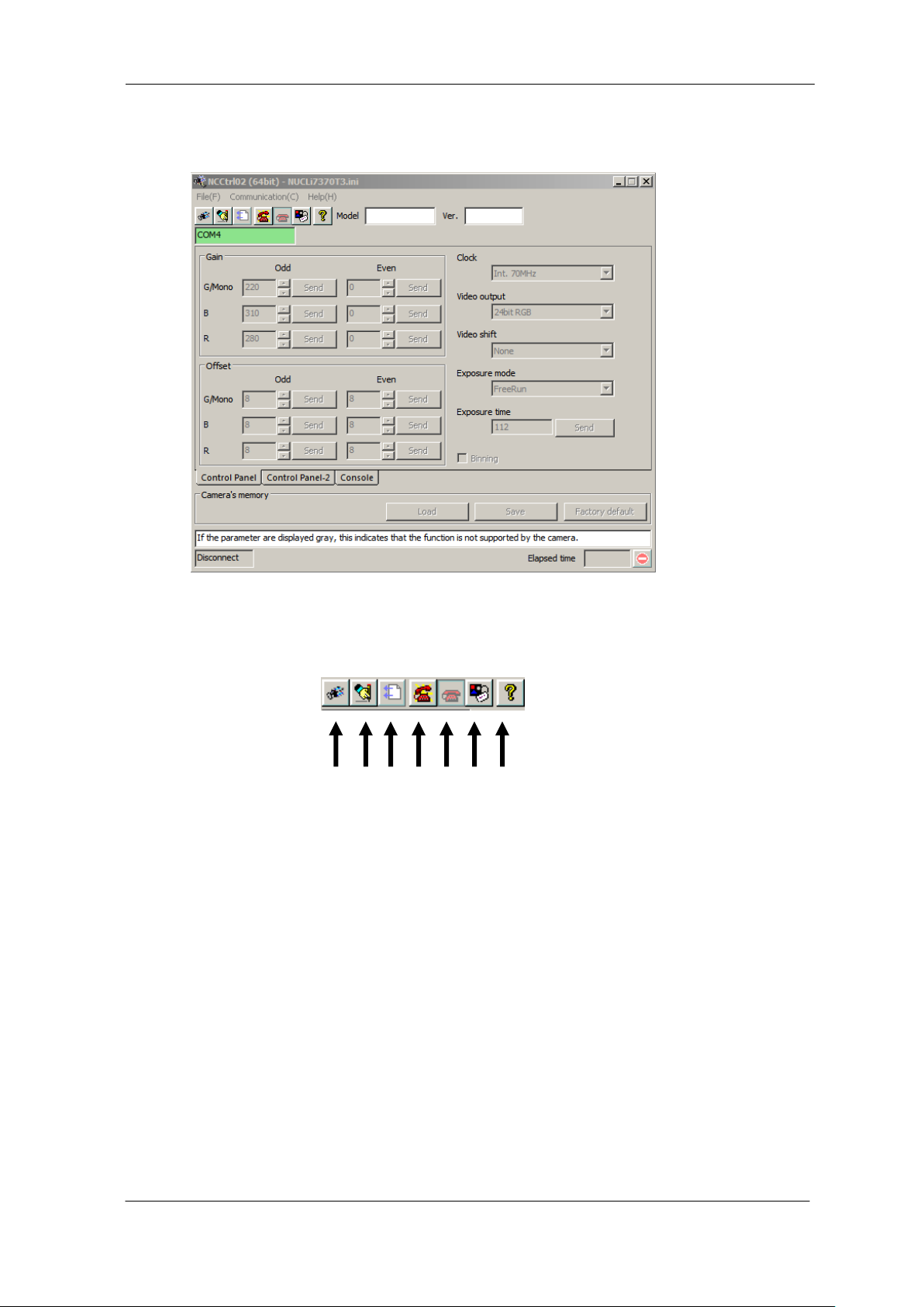
Start Windows Explorer and double-click the NCCtrl02.exe icon.
There are some buttons in the tool-bar. The function of each button is follows.
A: Open a camera setting file (*.ini file)
B: Export the parameters to text file (*.txt file)
C: Load the parameters from a text file (*.txt file)
D: Connect to the camera.
E: Disconnect from the camera
F: Communication settings
G: Version information.
SU2020/SU2025 UME-0021-03
Page 47
NED
47
8.5.3 Open the control setting file
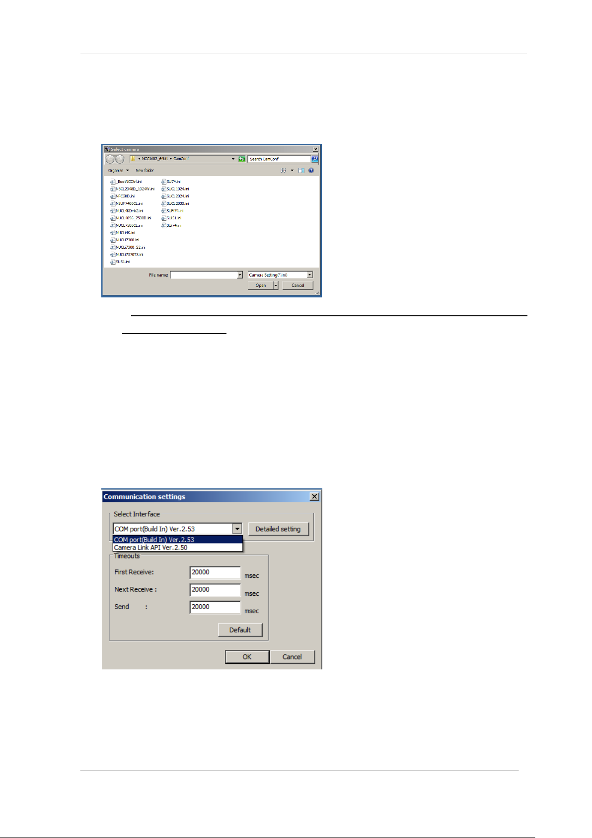
1) Click on tool-bar button “A”.
2) Select the appropriate setting file (*.ini file) and click on the "Open" button.
3) The setting is loaded, and each control parameter is initialized.
Note: If the parameters displayed are gray, this indicates that the camera does not
support the function.
NCCtrl memorizes automatically the setting file name that was last opened.
This file is automatically opened when NCCtrl is booted up.
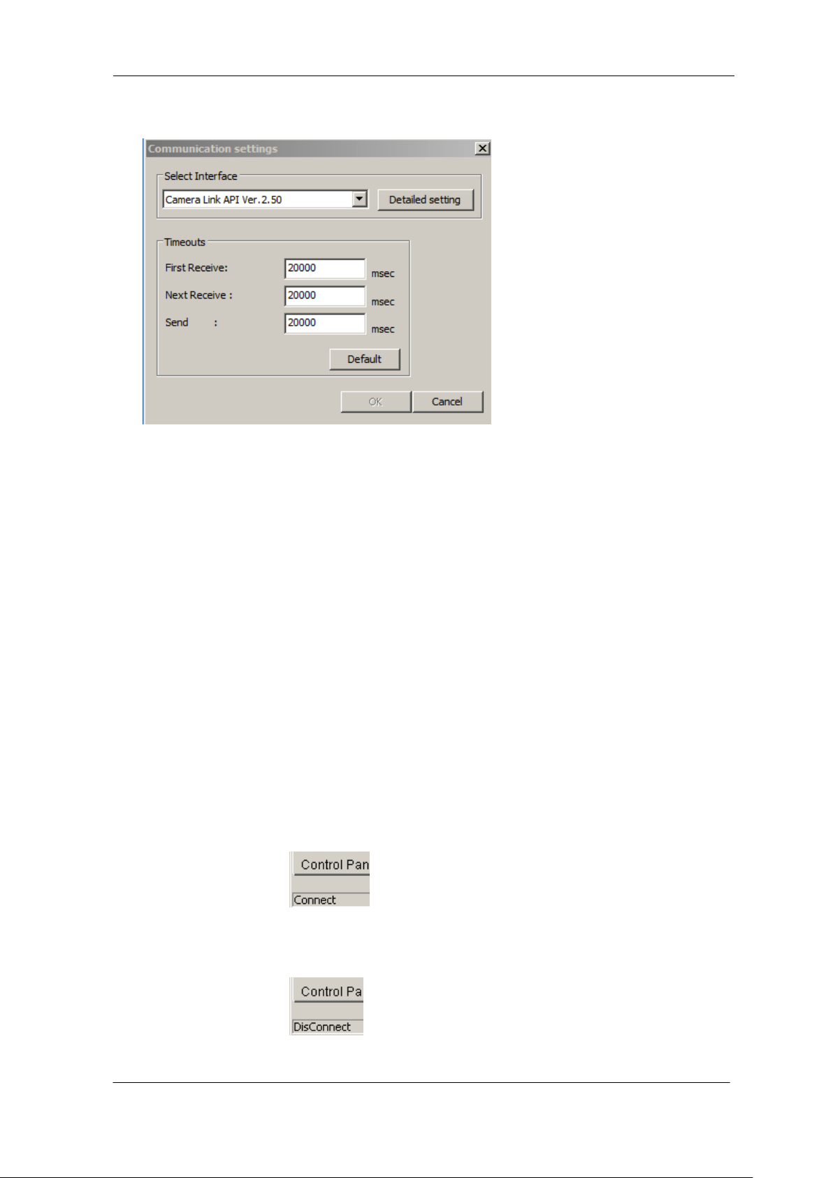
8.5.4 Selecting interface and Timeout setting
8.5.4.1 Selecting interface
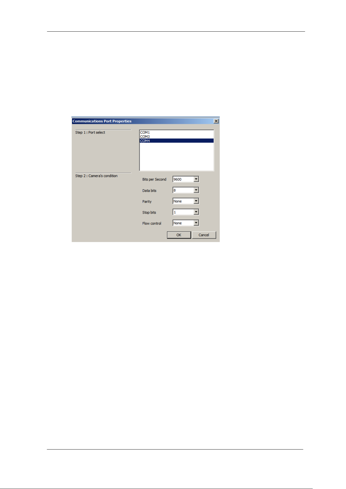
1) Click tool-bar button F.
2) Select the desired interface in the Drop-down-list-box.
3) Using the “Detailed setting” button, you can change the interface setting.
4) Click on the “OK” button to complete this operation. Click on the “Cancel” button to cancel
this operation.
UME-0021-03 SU2020/SU2025
Page 48
NED
48
Note: NCCtrl memorizes settings automatically. So you do not have to repeat this operation every
time.
8.5.4.2 Setting the COM port
1) Set each item as follows. (NED standard)
Unless in cases where different settings have been specified.
(1) Port: Select connecting port.
(2) Bits per Second: 9600
(3) Data bits: 8
(4) Parity: None
(5) Stop bits: 1
(6) Flow control: None
Note: Other parameter should not be used.
2) Click on the “OK” button to complete this operation.
Click on the “Cancel” button to cancel this operation.
Note: NCCtrl memorize settings automatically. So you do not have to repeat this operation every time.
SU2020/SU2025 UME-0021-03
Page 49
NED
49
8.5.4.3 Setting Camera Link
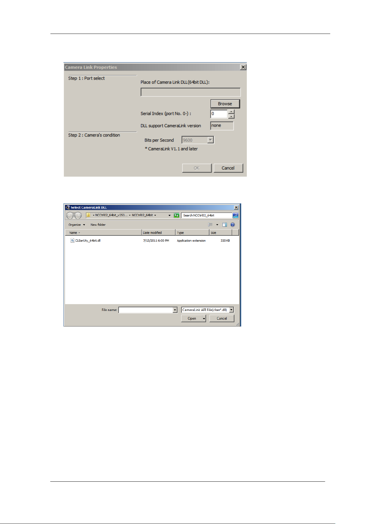
1) Enter the DLL file name of Camera Link API in the edit-box, or click “Browse” button and
select DLL file.
2) Enter value corresponding to the position of Camera Link cable to connect into the “Serial
Index” column.
3) Click on the “OK” button to complete this operation.
Click on the “Cancel” button to cancel this operation.
Note: NCCtrl memorize settings automatically. So you do not have to repeat this operation
every time.
Frame grabber manufacturers provide the DLL file for Camera Link API.
Some frame grabber boards are connected directly to the PC’s COM port.
In this case, set the interface to COM port (RS232C).
For details, please inquire with the frame grabber manufacturer.
UME-0021-03 SU2020/SU2025
Page 50
NED
50
8.5.4.4 Setting Timeout
1) Enter timeout values to each edit-box in milliseconds.
Click "Default" button to restore all timeout values to default settings.
The meanings of each timeout are as follows.
First Receive: Maximum time, allowed to arrival of first characters after command
transmission.
Next Receive :Maximum time, allowed to elapse between the arrival of two characters.
Send :Maximum time, allowed to completing of command transmission.
2) Click on the “OK” button to save the setting.
Click on the “Cancel” button to cancel the setting.
Note: NCCtrl memorizes settings automatically. So you do not have to repeat this operation
every time.
8.5.5 Connect
Click on tool-bar button D. Then you can control the camera.
8.5.6 Disconnect and exit program
Click on tool-bar button E. Then click the “X” button in the top right of the window.
SU2020/SU2025 UME-0021-03
Page 51
NED
51
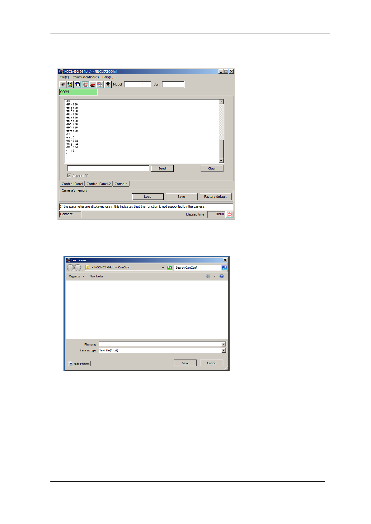
8.5.7 Check the contents of communication
Click on the "Console" tab at the bottom of the window to confirm the settings.
8.5.8 Export Parameters to text file
1) Click on tool-bar button B.
2) Input the desired file name and click on the “Save” button. The current settings value of each
item is saved in text format.
UME-0021-03 SU2020/SU2025
Page 52
NED
52
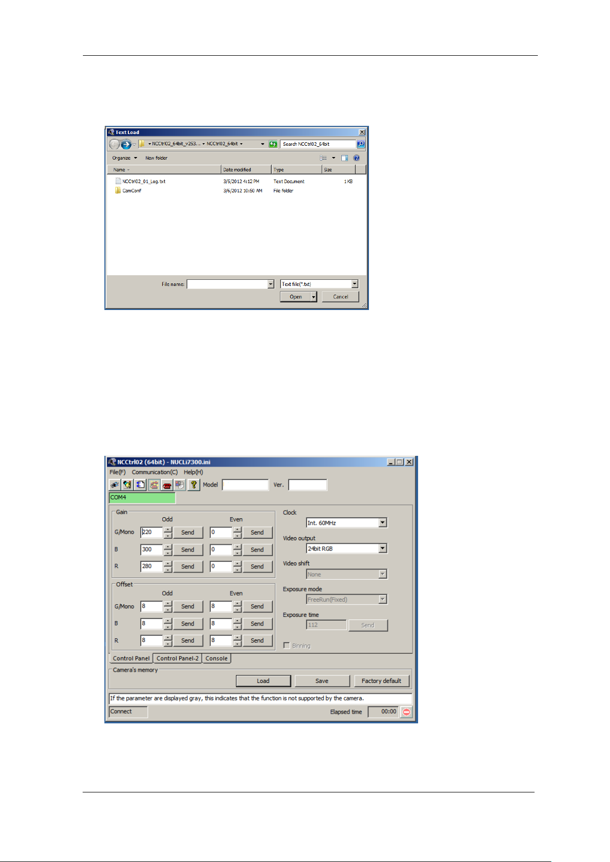
8.5.9 Import Parameters from text file
1) Select menu “File” – “Text Load”
2) Select the file name and click on the “Open” button.
Each command written in the text file is executed sequentially.
8.6 Control
The controllable functions and range of values differ for every camera.
For details, refer to the camera specifications. (Section.4)
SU2020/SU2025 UME-0021-03
Page 53
NED
53
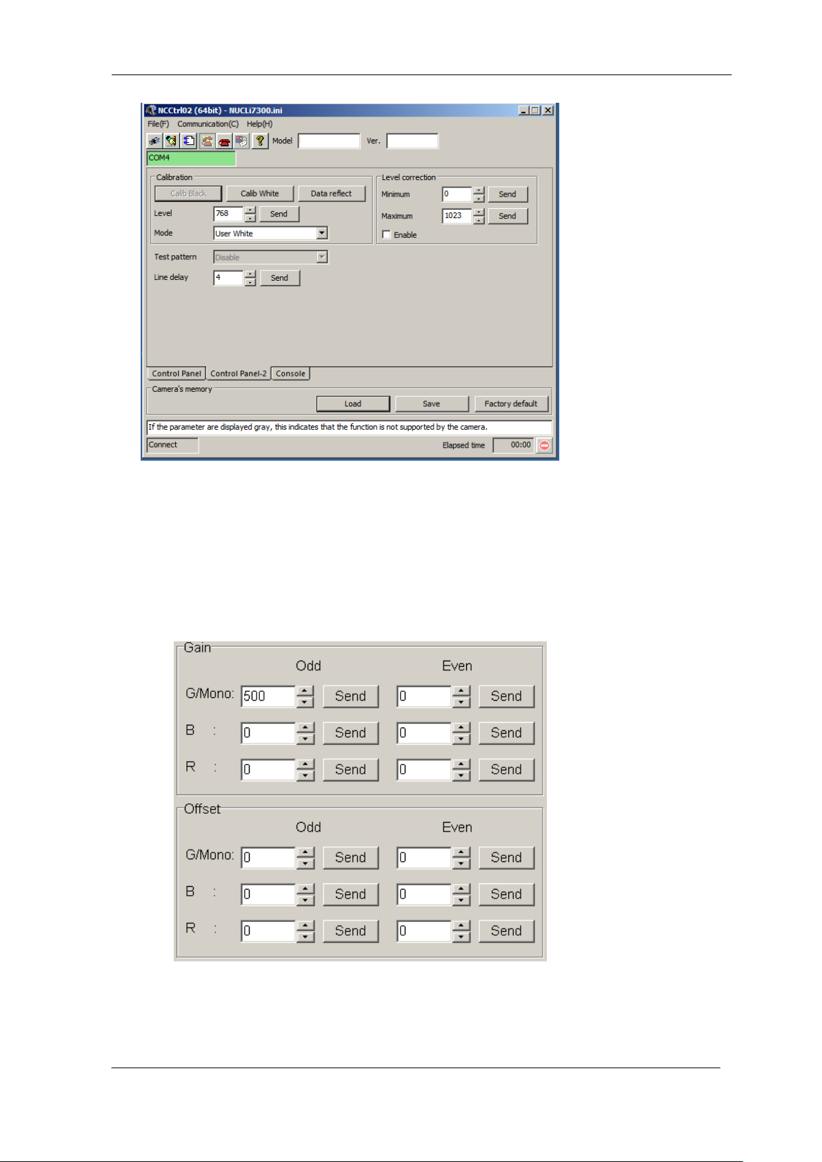
8.6.1 Gain and Offset
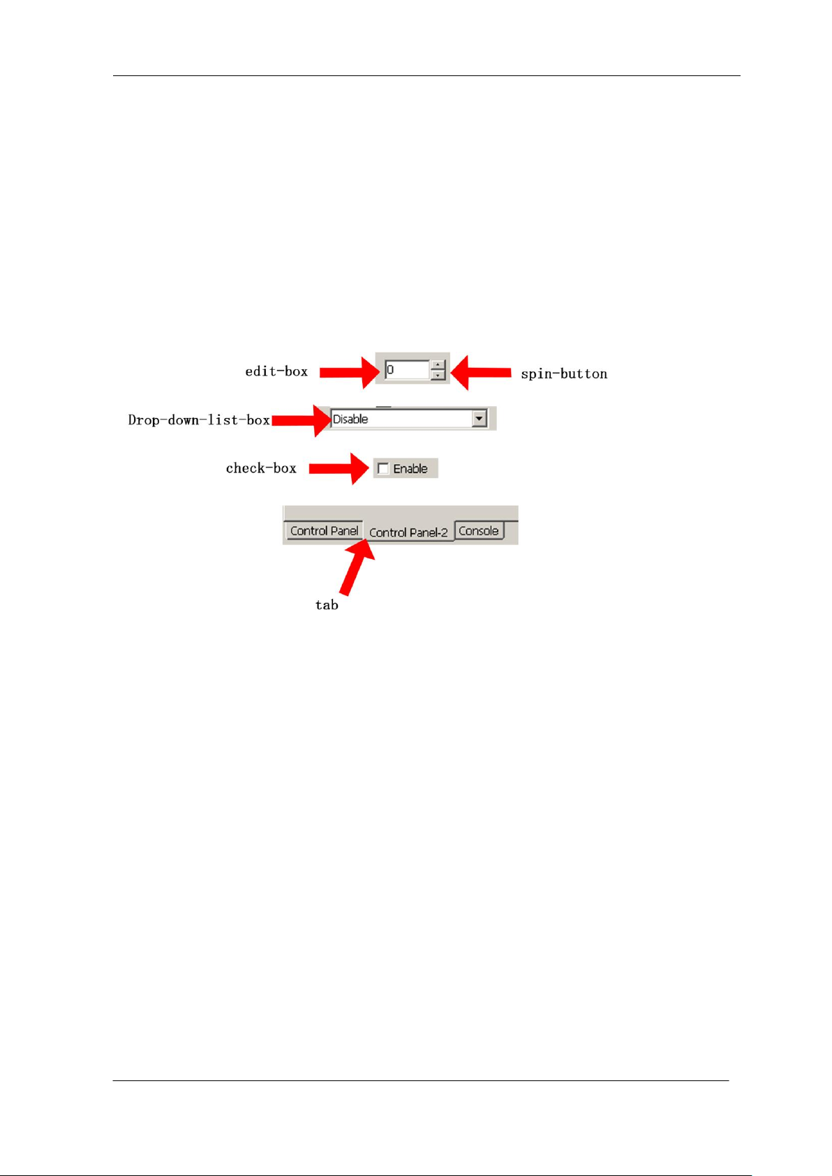
Enter the value directly into the edit-box or click on the spin-button to set the value.
Then, click on the “Send” button to send the command to the camera.
UME-0021-03 SU2020/SU2025
Page 54
NED
54
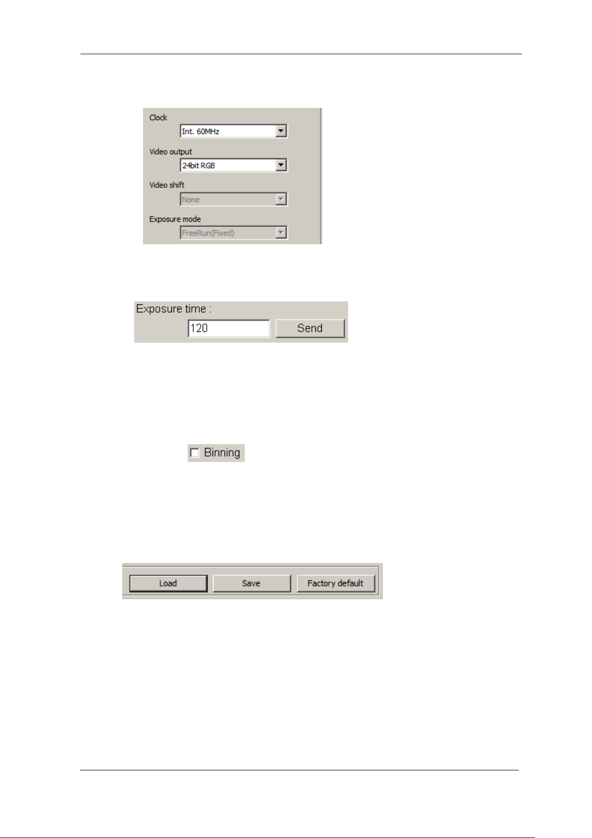
8.6.2 Clock, Video output, Video shift, Exposure mode
Every time you choose from the Drop-down-list-box, the command is sent to the camera.
8.6.3 Exposure time
Enter the value in the edit-box and click the “Send” button to send the command to the camera.
8.6.4 Binning
Every time you click the Check-box, the command is sent to the camera.
8.6.5 Camera Memory
a) “Load”: Load data from camera memory
b) “Save”: Save data into camera memory
c) “Factory default”: Restore camera memory data to factory settings.
SU2020/SU2025 UME-0021-03
Page 55
NED
55
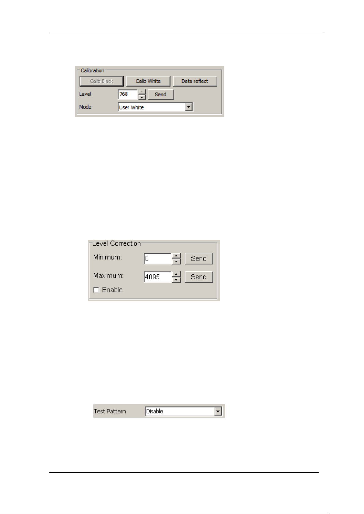
8.6.6 Calibration
a) ”Calib Black”: Acquisition of black data (When you do this please cover the lens.)
b) ”Calib White”: Acquisition of white data.
c) “Data reflect”: Save the calibration data to camera memory and apply the data.
d) “Level”: Enter the value directly in the edit-box or click the spin-button to set the value.
Then, click the “Send” button to send the command to the camera.
e) “Mode”: Every time you choose from the Drop-down-list-box, the command is sent to the
camera.
8.6.7 Level Correction
a) “Minimum”: Enter the value directly in the edit-box or click the spin-button to set the value.
Then, click the “Send” button to send the command to the camera.
b) “Maximum”: Enter the value directly in the edit-box or click the spin-button to set the value.
Then, click the “Send” button to send the command to the camera.
c) “Enable”: Every time you click the Check box, the command is sent to the camera.
8.6.8 Test Pattern
Every time you choose from the Drop-down-list-box, the command is sent to the camera.
UME-0021-03 SU2020/SU2025
Page 56
NED
56
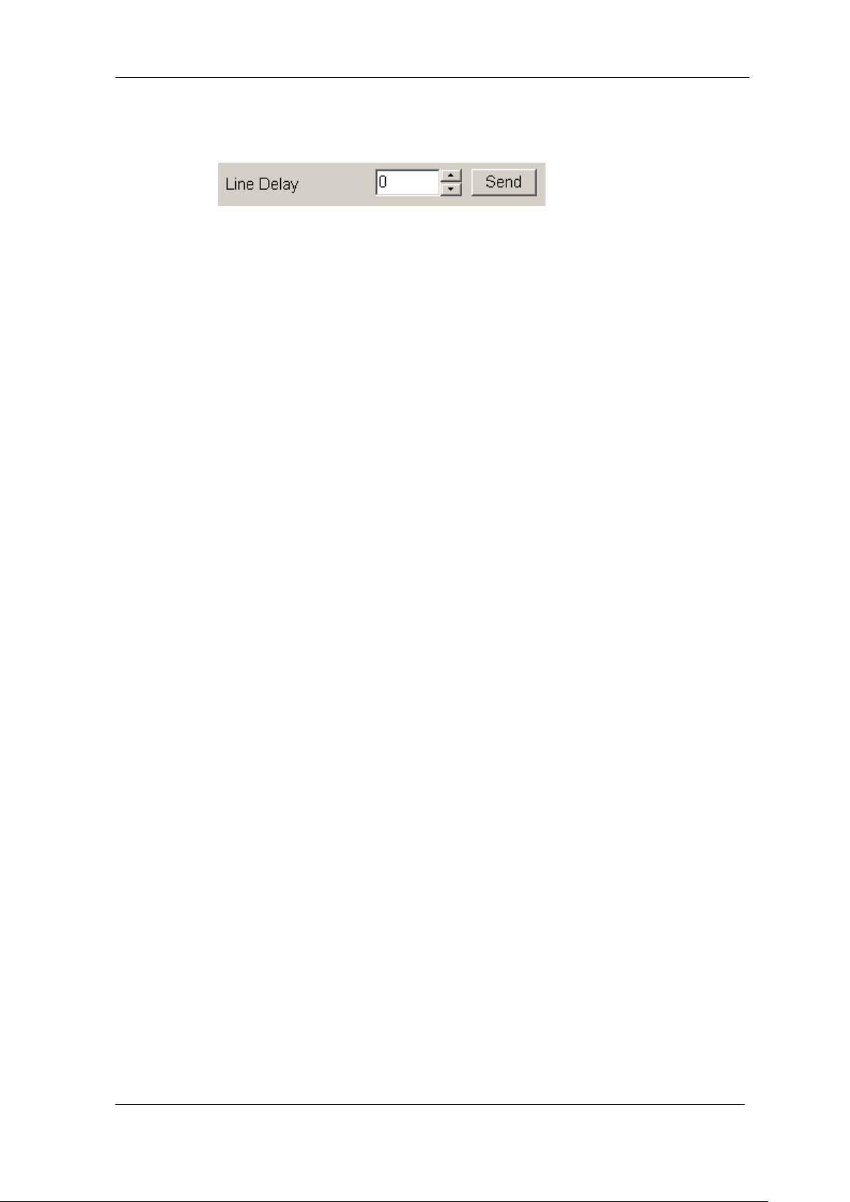
8.6.9 Line Delay
Enter the value directly in the edit-box or click the spin-button to set the value.
Then, click the “Send” button to send the command to the camera.
8.7 Software Upgrades
When you received the newest software from NED,
Please execute the following procedure.
8.7.1 NCCtrl upgrades
1) Check the old version of NCCtrl is not in operation.
2) Uninstall old version. (See “4.Uninstall”)
3) Install new version. (See “3.Software installation”)
8.7.2 Adding/Replacing control setting file
1) Check the old version of NCCtrl is not in operation.
2) Copy the control setting file(*.ini) to NCCtrl¥Camconf folder.
8.7.3 Adding/Replacing the interface Plug-in
1) Check the old version of NCCtrl is not in operation.
2) Copy the Plug-in file (*.dll) to the NCCtrl folder.
8.8 Data Transmission Programming
To make your own communication program, please refer to the sample programs in
NCCtrl¥SampleProgram folder.
SU2020/SU2025 UME-0021-03
Page 57

NED
57
8.9 NCCtrl Troubleshooting
8.9.1 You can not change the exposure time with NCCtrl
Cause:If these items are gray, the camera does not have a function to change exposure time.
Solution:First, change the exposure mode to “External Trigger”with NCCtrl.
Then, provide a periodic trigger signal to the camera from the frame grabber board.
Please refer to the frame grabber board specifications.
In this case, the trigger signal period is equal to exposure time.
8.10 Attention on use
1) Reproducing and distributing without notice part or all of this software and this manual is
prohibited.
2) Reverse engineering, decompiling, disassembling and modifying without notice part or all of
this software is prohibited.
3) The specification of this software and the contents of this manual may be changed by NED at
any time without notice.
UME-0021-03 SU2020/SU2025
Page 58

NED
58
9 Others
9.1 Notice
No part of this document may be reproduced in any form, in whole or in part, without the
express written consent of NED.
The contents of this document are subject to change without prior notice.
Every care has been taken in the preparation of this User’s Manual. If you should discover
any errors or omissions, please notify your nearest NED representative.
9.2 Contact for support
Nippon Electro-Sensory Devices Corporation
Head Office
2-5-12, Itachibori, Nishi-ku, Osaka 550-0012, Japan
Phone +81-6-6534-5300
Fax +81-6-6534-6080
Tokyo Office
Gibraltar Ohi BLD., Room No.402
1-45-2, Ohi, Shinagawa-ku, Tokyo 140-0014, Japan
Phone +81-3-5718-3181
Fax +81-3-5718-0331
West Japan Office
Twin Square 1-8-28 Enokida, Hakata-ku, Fukuoka, 812-0004, Japan
Phone +81-92-451-9333
Fax +81-92-451-9335
URL
http://ned-sensor.co.jp/en
E-Mail
[email protected]
SU2020/SU2025 UME-0021-03
Page 59

NED
59
9.3 Product Support
If there is a problem with your camera after checking it in accordance to the
troubleshooting, turn off the power and call your NED representative.
When contacting us with a problem, please inform us of the status of the camera.
You can get the status by
(1) executing the “ l ” command.
The example of the camera status.
l
>OK
>Type=SU2025
>Ver.=1.3
>g0
>a4
>o0
>v0
>t0
>l
UME-0021-03 SU2020/SU2025
Page 60

NED
60
Revision Number
Date
Changes
01
12 July. 2012
Initial release
02
10 Oct. 2012
Update the EU Harmonised Standards
03
28 Oct. 2013
Product Warranty、Responsivity、
Offset value
Revision History
SU2020/SU2025 UME-0021-03
 Loading...