

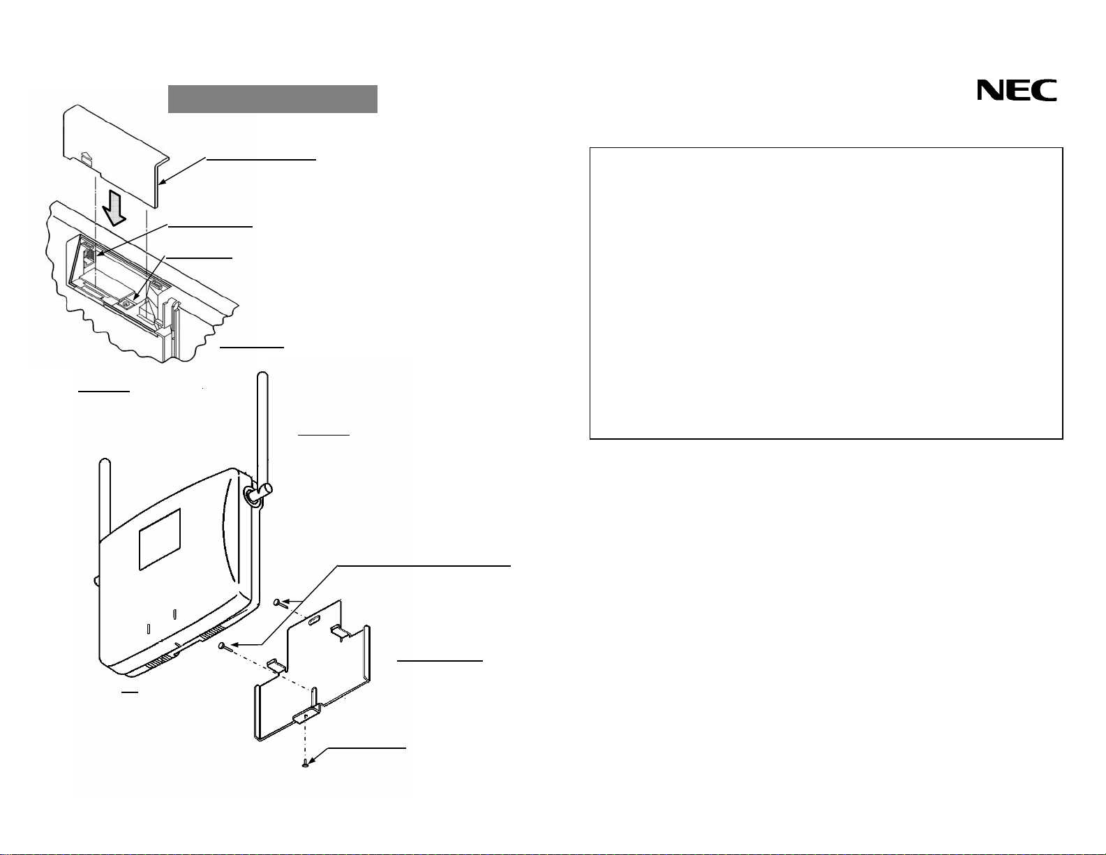
Attach
l
ment mode
Connector cover
Modular jack
DC in jack
1. Connect the telephone line.
2. Connect the AC adaptor.
(The AC adaptor may be required in some
conditions. Please contact service personnel
for detailed information.)
3. Slide the connector cover to the direction
of the arrow, and put in it.
Rear view
Attention
Over 3.9 inches / 100 mm
Leave space for the antenna.
1. Screw the mounting tag on the wall.
2. Attach the ZT to the mou nting tag.
3. Screw the bottom of ZT to t he mounting tag.
Attention
When the wall material is weakly,
First, pit the wall.
Second, insert the anchor into th e ho le.
Third, screw the mounting tag to
the anchor of the wall.
(Ex. Gypsum board)
Screw of the mounting tag
ZT
Mounting tag
Screw of ZT
ZTⅢ INSTALLATION GUIDE
FCC PART 15
This equipment has been tested and found to comply with the limits for a Class B
digital device, pursuant to Part 15 of the FCC Rules. These limits are designed to
provide reasonable protection against harmful interference in a residential
installation. This equipment generates, uses and can radiate radio frequency energy
and, if not installed and used in accordance with the instructions, may cause harmful
interference to radio communications. However, there is no guarantee that
interference will not occur in a particular installatio n. If this equipment does cause
harmful interference to radio or television reception, which can be determined by
turning the equipment off and on, the user is encouraged to try to correct the
interference by one or more of the following measures:
SAFETY
Warning
Notice
Radio specifications
NEC Infrontia Corporation
ISSUE 1 Printed in Japan
Reorient or relocate the receiving ant e nna
Increase the separatio n between the equipment and receive r
Connect the equipment into an outlet on a circuit different from that to which
the receiver is connected.
Consult the dealer or an experienced radio/TV technician for help.
This equipment has been tes ted for safety and found to comply with all applicable
requirements of UL/CSA 60950-1.
Note to installers: In order to comply with the FCC RF exposu re requirements ZT must
be installed with a minimum separation distance of 20 cm from the an tennas to the
user or nearby persons.
Install on a secured mounting surface. Take care to attach unit securely.
This device may suffer damage if dropped.
ZT contains two antennas for diversity purposes, only one antenna transmits during
normal operation.
This document contains proprietary information and may not be reproduced in any
form without express written consent of NEC Corporation. The information contained
herein is subject to change without notice at the discretion of NEC Corporation.
Frequency range : 1920.35 – 1929.65Mz
Communication Channels : 3 per ZT simultaneous
 Loading...