

NEC of America 58155TRP User Manual

Document ID: 141-DOC000008-E
iPasolink Installation and
Commissioning Guide
Release: Beta Draft
Version: 0.3

Version
Date
Modifications Made
0.1
24 May 2011
Alpha Draft
0.2
25 May 2011
Preliminary Draft
0.3
21 June 2011
Beta Draft
Copyright Notice
Copyright © 2000-2011. All rights reserved. No part of this book or manual may be reproduced or transmitted
in any form or by any means, electronic or mechanical, including photocopying, recording, or by any
information storage and retrieval system, without the express written permission from NEC Corporation.
Warning and Disclaimer
While every effort has been made to make this document as complete and as accurate as possible, NEC
Corporation does not accept any responsibility for poorly designed or malfunctioning networks. The
information provided in this document is on an “as is” basis and is subject to change without prior notice. The
author, NEC Corporation, shall have neither liability nor responsibility to any person or entity with respect to
any loss or damage arising from the information contained in this document or from the use of equipment or
software that might accompany it. The opinions expressed in this document are not necessarily those of NEC
Corporation.
Trademark Acknowledgments
All terms mentioned in this book that are known trademarks or service marks have been appropriately
capitalized. All trademarks duly acknowledged. NEC Corporation cannot attest to the accuracy of third-party
information. Use of a term in this document should not be regarded as affecting the validity of any trademark
or service mark.
Technical Support Information
NEC Corporation customers can contact NEC Corporation Support Center (TSC) 24x7x365 for any assistance
through helpline, fax or email.
- Phone(s): +91 80 41719090, +91 80 26591082, +91 80 26591080
- Fax: +91 80 26591079
- Skype: tscsupport123
Revision History

Your Feedback is valuable to us!
Your evaluation of this
document
Presentation: (Introductions, Procedures, Illustrations, Completeness, Level of
Detail, Organization, Appearance)
Good
Fair
Average
Poor
Bad
N/A
Intelligibility: (Language, Vocabulary, Readability and Clarity, Technical Accuracy,
Content)
Good
Fair
Average
Poor
Bad
N/A
Accessibility: (Contents, Index, Headings, Numbering, Glossary)
Good
Fair
Average
Poor
Bad
N/A
Your suggestions for
improving this
document
Improve the
overview/introduction
Make it more
concise/brief
Improve the
Contents
Add more step-by-step
procedures/ tutorials
Improve the organization
Add more
troubleshooting
information
Include more figures
Make it less technical
Add more examples
Add more/better quick
reference aids
Add more detail
Improve the index
Other Suggestions:
If you wish to be contacted regarding your comments, please provide your contact details:
Name:
Company:
Postcode:
Address:
Telephone:
Email:
Your opinion is of great value and will help us improve the quality of our product documentation and offer
better services to you. Please take few moments to provide us your opinion of this document.

Table of Contents
List of Figures vii
List of Tables viii
Chapter 1 Using this Guide 11
Who This Guide Is For ............................................................................................................... 11
What This Guide Covers ............................................................................................................. 11
What You Should Already Know .............................................................................................. 12
Safety Signs Conventions ............................................................................................................ 12
Typographical Conventions ........................................................................................................ 13
Mouse Operation Conventions .................................................................................................. 13
Chapter Organization ................................................................................................................... 14
Using NEC Corporation Product Documentation ................................................................. 15
Related Documents ...................................................................................................................... 16
Chapter 2 Understanding Installation, Commissioning, and Testing Process17
Installation and Commissioning Process Overview ................................................................ 18
Understanding Installation Procedure ....................................................................................... 18
Understanding Commissioning Procedure ............................................................................... 19
Chapter 3 Observing Safety Guidelines 21
Safety Standard Compliance........................................................................................................ 21
Safety Recommendations ............................................................................................................ 22
General Safety Guidelines ......................................................................................................... 22
Maintaining Safety with Electricity ............................................................................................ 22
Preventing Electrostatic Discharge Damage ................................................................................ 23
Site Environment ...................................................................................................................... 23
General Site Requirements .......................................................................................................... 23
Preventive Site Configuration ..................................................................................................... 24
Configuring Equipment Racks .................................................................................................. 24
Working with Power Supply Unit .............................................................................................. 24
Preventing Damage to Card and Pluggable Module ............................................................... 25
Dissipating Static Electricity ....................................................................................................... 26
Controlling Equipment Environment ....................................................................................... 27
Using Optical Fibers .................................................................................................................... 27
Handling Optical Fibers ........................................................................................................... 27
Splicing Optical Fibers .............................................................................................................. 28
Repairing Optical Fibers ........................................................................................................... 28
iv

Chapter 4 Receiving and Unpacking Network Element 31
Receiving and Unpacking Network Element Process............................................................. 31
Handling Package ......................................................................................................................... 32
Verifying Shipment ....................................................................................................................... 32
Storing Packages ........................................................................................................................... 32
Unpacking the Network Element .............................................................................................. 32
Chapter 5 Installing the Network Element 37
Site Preparation ............................................................................................................................. 37
Installation Guidelines ................................................................................................................. 37
Installing Network Element into the Rack ............................................................................... 38
Connecting the Grounding Cables............................................................................................. 39
Connecting the Power Cables ..................................................................................................... 40
Chapter 6 Installing OAM Interfaces 41
Alarm Cable Connection ............................................................................................................. 41
RF SW/FAN Cable Connection ................................................................................................ 42
Clock Cable Connection .............................................................................................................. 42
NMS Cable Connection ............................................................................................................... 43
GPS Clock Cable Connection .................................................................................................... 44
Chapter 7 Installing PDH Cards 45
DS1 Connection ........................................................................................................................... 45
E3/DS3 Connection .................................................................................................................... 46
MODEM-A Connection ............................................................................................................. 46
MAIN-A Card Connection ......................................................................................................... 47
Chapter 8 Installing Optical Cards 49
STM-1/OC-3 Connection ........................................................................................................... 49
OC-12 Connection ....................................................................................................................... 49
Chapter 9 Installing Ethernet Card 51
GbE Connection .......................................................................................................................... 51
Chapter 10 Node Commissioning 53
Connecting the PC to the NMS interface of the Network Element .................................... 53
Logging into an Uncommissioned Network Element ............................................................ 54
Configuring Parameters in SLAT Page ..................................................................................... 55
Setting Ethernet IP, Subnet Mask, Router ID, and Port Rate on the Network Element .. 56
Verifying the Serial Numbers of Cards and Pluggable Modules of the Network Element57
Setting Network Element Date and Time ................................................................................ 58
Nominating a Synchronization Reference Clock Source for the Network Element .......... 59
v

Backing Up or Restoring Network Element Configuration Data ......................................... 59
Appendix I Recording Data and Test Results 61
Site Verification Checklist ........................................................................................................... 61
Commissioning and Testing Report .......................................................................................... 63
Receiver Sensitivity Measurements for OC-3 ........................................................................... 63
Receiver Sensitivity Measurements for OC-12 ......................................................................... 63
Receiver Sensitivity Measurements For GbE ........................................................................... 64
Synchronization Tests .................................................................................................................. 64
BER (BIT Error Rate) Performance.......................................................................................... 65
Appendix II General Configuration 67
Switch ON Node and PC Configuration .................................................................................. 67
Logging into the System .............................................................................................................. 67
Configuring OSPF Parameters ................................................................................................... 68
Configuring E3/DS3 Ports ......................................................................................................... 68
Configuring VCG Ports ............................................................................................................... 70
Adding New VC to VCG ............................................................................................................ 71
Configuring Ethernet Ports ......................................................................................................... 71
Configuring Timing Manager ...................................................................................................... 72
Checking Alarms ........................................................................................................................... 73
Appendix III General Procedures 75
Cleaning Fiber Connectors .......................................................................................................... 75
Cleaning Optical Connectors ...................................................................................................... 76
Ejecting Cross-Connect Cards .................................................................................................... 77
Inserting and Ejecting Cards ....................................................................................................... 77
Inserting and Ejecting Fan Tray Unit (FAN-A) ....................................................................... 80
Inserting and Ejecting Air Filter Unit ........................................................................................ 81
Appendix IV Connector Pin Assignment 85
RF SW/FAN ALM 1 Connector ............................................................................................... 85
ALM I/O Connector ................................................................................................................... 85
5 MHz/10 MHz ............................................................................................................................ 86
1 PPS Connector........................................................................................................................... 86
NE1 Connector ............................................................................................................................ 86
NMS Connector ............................................................................................................................ 87
EXT CLK Connector .................................................................................................................. 87
160 PIN LFH DS1 Connector (120 Ohm)............................................................................... 88
MDR Connector ........................................................................................................................... 93
Glossary of Terms 101
Index 103
vi

List of Figures
Figure 1: Installation and Commissioning Process Flow ............................................................... 18
Figure 2: Receiving and Unpacking Process .................................................................................... 31
Figure 3: Warning Logo ...................................................................................................................... 33
Figure 4: Starps on the Packing Box ................................................................................................. 33
Figure 5: Reinforced Packing Tape .................................................................................................... 34
Figure 6: Silica Gel in the Packing Box ............................................................................................. 34
Figure 7: Taking Packing Cushion and Equipment ........................................................................ 35
Figure 8: Removing Cushions from the Packing Box .................................................................... 35
Figure 9: Antistatic Bag ....................................................................................................................... 36
Figure 10: Installing Chassis into the Rack ....................................................................................... 39
Figure 11: Connecting Power Cables (PS-A Card) .......................................................................... 40
Figure 12: Alarm Connection ............................................................................................................. 41
Figure 13: FAN Alarm Connection ................................................................................................... 42
Figure 14: Clock Connection .............................................................................................................. 43
Figure 15: NMS Cable Connection.................................................................................................... 43
Figure 16: NE1 Cable Connection .................................................................................................... 43
Figure 17: GPS Clock Connection .................................................................................................... 44
Figure 18: DS1 Connection (DS1 Card) ........................................................................................... 45
Figure 19: DS3 Connection (ST6E3 Card) ....................................................................................... 46
Figure 20: MAIN-A Card Connection (DS1 Connector) .............................................................. 47
Figure 21: OC-3 Connection .............................................................................................................. 49
Figure 22: OC-12 Connection ............................................................................................................ 50
Figure 23: GbE Connection (MAIN-A Card) ................................................................................. 51
Figure 24: PC connected to the Node ............................................................................................... 68
Figure 25: Inserting Card into the Chassis ....................................................................................... 78
Figure 26: Pushing Ejector Lever Inwards ....................................................................................... 78
Figure 27: Pulling Ejector Lever Outwards ...................................................................................... 79
Figure 28: Sliding the Card Outwards ............................................................................................... 79
Figure 29: Installing Fan Tray Unit (FAN-A) .................................................................................. 80
Figure 30: Installing FAN-A (II) ........................................................................................................ 80
Figure 31: Uninstalling FAN-A from the Chassis ........................................................................... 81
Figure 32: Installing Air Filter Tray Unit (I) ..................................................................................... 82
Figure 33: Installing Air Filter Tray Unit (II) ................................................................................... 82
Figure 34: Unstalling the Air Filter Unit (I) ...................................................................................... 83
Figure 35: Unstalling the Air Filter Unit (II) .................................................................................... 83
vii

List of Tables
Table 1: Site Verification Checklist ................................................................................................ 61
Table 2: Commissioning and Testing Report ............................................................................... 63
Table 3: Receiver Sensitivity Measurements for OC-3 ................................................................ 63
Table 4: Receiver Sensitivity Measurements for STM-4/OC-12 ............................................... 63
Table 5: Receiver Sensitivity Measurements For GbE ................................................................ 64
Table 6: Syncronization Tests ......................................................................................................... 64
Table 7: BER (BIT Error Rate) Performance .............................................................................. 65
Table 8: PDH Interface Parameters ............................................................................................... 70
Table 9: RF SW/FAN ALM 1 Connector .................................................................................... 85
Table 10: ALM I/O Connector ........................................................................................................ 85
Table 11: 5 MHz/10 MHz Connector ............................................................................................. 86
Table 12: 1 PPS Connector ............................................................................................................... 86
Table 13: NE1 Connector ................................................................................................................. 86
Table 14: NMS Connector ................................................................................................................ 87
Table 15: EXT CLK Connector ....................................................................................................... 87
Table 16: 160 PIN LFH Connector (120 Ohm) ............................................................................ 88
viii

NOTE: THE NEC iPASOLINK 5.8 GHz RADIOS MUST BE
PROFESSIONALLY INSTALLED AND ARE THEREFORE EXEMPT FROM
THE ANTENNA RESTRICTIONS (FCC PART 15.203).
NOTE: THE NEC iPASOLINK 5.8 GHz RADIOS USE QAM MODULATED
SIGNALS AND IT IS CERTIFIED FOR OPERATION UNDER PART 15.247
OF THE FCC REGULATIONS. THE NEC iPASOLINK 5.8 GHz RADIO IS
DESIGNED TO OPERATE IN A POINT-TO-POINT COMMUNICATIONS
LINK USING THE 5.725 – 5.850 GHz BAND. THE RADIO WILL PROVIDE A
TRAFFIC CAPACITY OF 155 MBP/S USING 128 OR 256 QAM
MODULATION. THE NEC iPASOLINK 5.8 GHz RADIOS ARE NOT
DESIGNED TO BE INSTALLED OR USED BY THE GENERAL PUBLIC,
THE INSTALLATION REQUIREMENTS ARE SUCH THAT CONSUMERS
OR BUSINESS PERSONS DO NOT HAVE THE TECHNICAL SKILLS TO
PROPERLY INSTALL AND COMMISION THE iPASOLINK RADIO.
NOTE: THE NEC iPASOLINK 5.8 GHz RADIO WILL BE SOLD NY NEC
CORPORATION OF AMERICA AND IT’S SALESPERSONS OR
AUTHORIZED AGENTS ONLY, AND WILL BE INSTALLED BY TRAINED
PROFESSIONAL PERSONNEL.
NOTE: THE NEC iPASOLINK 5.8 GHz RADIOS WILL BE USED FOR
FIXED POINT TO POINT APPLICATIONS. THE iPASOLINK RADIO
UTILIZES A PARABOLIC ANTENNA THAT REQUIRES PROFESSIONAL
INSTALLERS FOR PATH ALIGNMENT.
WARNING: THE MAXIMUM RF TRANSMIT POWER OF THE NEC
iPASOLINK 5.8 GHz RADIO IS 1.0 WATT (+30.0 dBm). THE TECHNICIAN
CAN SET THE OUTPUT POWER FROM +10 dBm TO +30 dBm DURING
INSTALLATION. THE METHOD OF ADJUSTING THE OUTPUT POWER
IS DESCRIBED IN SECTION III OF THE INSTALLATION MANUAL AND
REQUIRES THE USE OF A LAPTOP COMPUTER. THE NEC iPASOLINK
5.8 GHz RADIO IS SOLD WITHOUT ANTENNAS AND SUPPORTING
HARDWARE.
ix

WARNING: Changes or modifications not expressly approved by the party responsible
for compliance could void the user’s authority to operate the equipment.
NOTE: This equipment has been tested and found to comply with the limits for a Class
A digital device, pursuant to part 15 of the FCC Rules. These limits are designed to provide reasonable protection against harmful interference when the equipment is operated
in a commercial environment. This equipment generates, uses, and can radiate radio
frequency energy and, if not installed and used in accordance with the instruction
manual, may cause harmful interference to radio communications. Operation of this
equipment in a residential area is likely to cause harmful interference in which case the
user will be required to correct the interference at his own expense.
NOTE: This equipment complies with the FCC RF radiation exposure limits set forth
for an uncontrolled environment. This equipment should be installed and operated with
a minimum distance of 228.04 centimeters between the radiator and your body.
NOTE: The antennas used for this transmitter must be installed to provide a separation
distance of at least 228.04 cm from all persons and must not be located or operating in
conjunction with any other antenna or transmitter.
NOTE: To comply with FCC RF exposure compliance requirements, a separation
distance of at least 228.04 cm must be maintained between the user and antenna when
the product is used with a parabolic 31dBi antenna in point-to-point applications.
x

This section describes who should read this guide, how it is organized, and what conventions are
Chapter 1
Using this Guide
IN THIS CHAPTER
Who This Guide Is For .................................................................................. 11
What This Guide Covers ................................................................................ 11
What You Should Already Know ................................................................. 12
Safety Signs Conventions ............................................................................... 12
Typographical Conventions ........................................................................... 13
Mouse Operation Conventions ..................................................................... 13
Chapter Organization ..................................................................................... 14
Using NEC Corporation Product Documentation.................................... 15
Related Documents ......................................................................................... 16
used in the document.
Who This Guide Is For
This document is intended for Technician or Field engineers who install and commission
hardware or software on the customer premises.
What This Guide Covers
This document provides information to install the product and to initially configure the product
to the point of verifying proper operation of the product in the network. The information
provided in this document includes hardware/software installation, provision specific protocols,
user accounts, services, interfaces, and related items to support the design of the network, and/or
the network application in which the product is installed. This document does not cover
installation of racks, electrical wiring, raceways, and other supporting equipments.
11
iPasolink250 Installation and Commissioning Guide Document ID: 141-DOC000008-E
What You Should Already Know
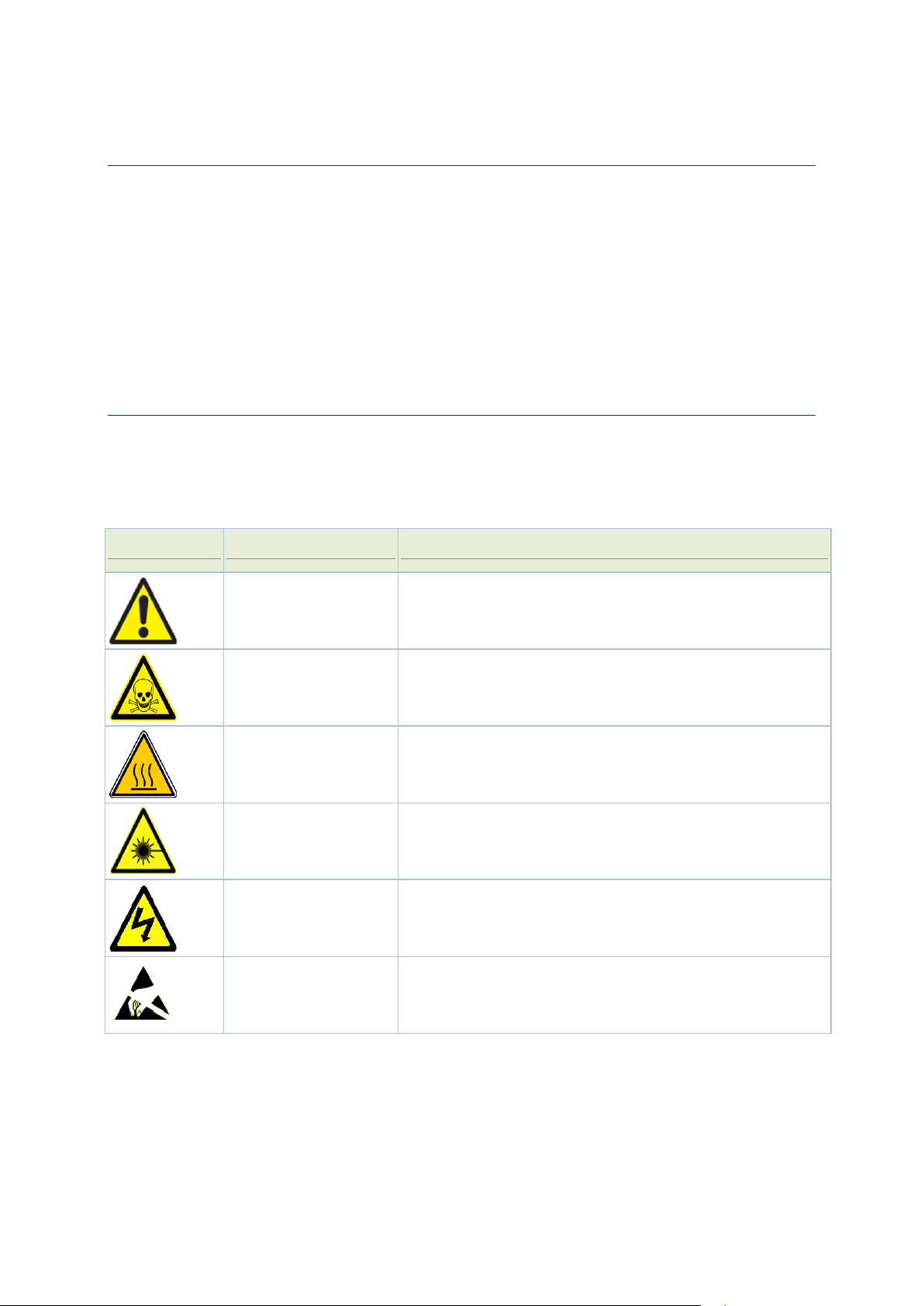
Symbols
Meaning
Represents
Caution
Situations that could result in equipment damage or loss of
data.
Danger
Situation that could cause bodily injury. Failure to observe this
precaution may result in personal injury, death, or equipment
damage.
Hot Surface
Situation that could result in bodily burns.
Optical Safety
Staring directly into the optical connector output beam may
cause irreparable damage to your eyes and even leading to loss
of eye sight.
Electric Shock Risk
Failure to observe this precaution may result in personal injury,
death, or equipment damage.
Static Discharge
Warning
Handle the equipment wearing a grounding wrist strap to
discharge the static buildup. Failure to observe this precaution
may result in equipment damage.
Before you read this Guide you need to be comfortable installing and commissioning hardware
or software on the customer premises. You must have prior experience handling equipment
under variety of circumstances.
Personnel working directly on equipment must be:
Trained, authorized, and qualified to carry out the tasks required.
Able to follow safety guidelines specific to the product and all local customer-specific safety
procedures.
Safety Signs Conventions
To prevent personal injury, equipment damage, and service interruptions, you must follow all
precautionary messages given in the document in addition to all the local safety standards
required by your company. The following symbols inserted in the document at various places
represent important situations.
12

Chapter 1 Using this Guide
Typographical Conventions
Formatting Convention
Type of Information
Procedures
Step-by-step procedures. You can follow these instructions to
complete a specific task.
Special Bold
Items you must select, such as menu options, command buttons,
or items in a list.
Emphasis
Use to emphasize the importance of a point or for variable
expressions such as parameters.
CAPITALS
Names of keys on the keyboard, for example, SHIFT, CTRL, or
ALT.
KEY+KEY
Key combinations for which the user must press and hold down
one key and then press another, for example, CTRL+P, or
ALT+F4.
NOTE:
Means reader take note. Notes contain helpful suggestions or
references to materials not contained in this manual.
Convention
Description
Click
Refers to pressing and releasing a mouse button to select a screen object.
Double-click
Refers to pressing and releasing a mouse button twice in succession while the cursor
is positioned over an object on-screen.
Drag
Refers to the function of the mouse by which an element on the screen of a monitor
is moved with the cursor, while holding down the mouse button and moving the
mouse.
Right-click
Refers to pressing the right button on a two-button mouse.
Wheel button
Refers to the third (middle) button on the mouse.
Before you start using this guide, it is important to understand the terms and typographical
conventions used in the document. The following kinds of formatting in the text identify special
information.
Mouse Operation Conventions
13

iPasolink250 Installation and Commissioning Guide Document ID: 141-DOC000008-E
Chapter Organization
Chapter
Scope
Understanding Installation and
Commissioning Process
see
"
Understanding Installation,
Commissioning, and Testing Process
"
on page 17
This chapter provides an overview of the Installation,
Commissioning, and Testing process flow of iPasolink
network element.
Observing Safety Guidelines
on page 21
This chapter contains safety guidelines that you must follow
for personal safety and to operate the iPasolink network
element correctly. It also describes about the site environment
and instructions to be followed during site preparation and
equipment rack configuration.
Receiving and Unpacking Network
Element
on page 31
This chapter describes the procedures to be followed during
receiving and unpacking of the iPasolink network element. It
includes shipment verification, handling packages, and
unpacking the equipment.
Installing the Network Element
on page
37
This chapter describes procedures to be followed when
installing iPasolink network element. It includes preparing site
for installation, installation guide lines, installing network
element into the rack, connecting power cables and grounding
cables.
Installing OAM Interfaces
on page 41
This chapter describes the OAM interface configuration
supported in iPasolink network element.
Installing PDH Cards
on page 45
This chapter describes the PDH card configuration supported
in iPasolink network element.
Installing Optical Cards
on page 49
This chapter describes the optical card configuration which
includes STM-1/4 connections.
Installing Ethernet Card
on page 51
This chapter describes the Ethernet configuration which
includes GbE connection.
Node Commissioning
on page 53
This chapter describes the commissioning procedures that
have to be performed on a newly installed iPasolink network
element. It includes logging into a uncommissioned network
element, downloading software from SLAT page, setting
Ethernet parameters, setting network element date and time,
and nominating synchronization clock reference for the
network element.
Recording Data and Test Results
on
page 61
This appendix provides various forms to record system data
and test results during the commissioning process.
General Configuration
on page 67
This appendix describes the general procedures for
configuring iPasolink network element. It includes switching
ON the node and PC configuration, logging into the network
element, configuring optical ports, OSPF, Ethernet ports,
VCG ports, timing manager, and checking alarms.
The rest of this document is organized as follows:
14

Chapter 1 Using this Guide
General Procedures
on page 75
This chapter describes the procedures to be followed when
cleaning and inspecting optical and fiber connectors. It also
describes the procedure to be followed during inserting and
ejecting of cards.
Connector Pin Assignment
on page 85
This appendix provides connector pin details used for
installing the network element.
Using NEC Corporation Product Documentation
The following NEC Corporation product documentation set helps you use the range of NEC
Corporation products:
The Hardware Description Guide explains hardware configuration, functions, capabilities,
limitations, and physical characteristics of the product.
The Installation and Commissioning Guide provides information on installing the product and to
initially configuring it to the point of verifying its proper operation in the network.
The User Interface Guide introduces and orients service providers to the content, function, and
organization of the user interface that support the network elements.
The Planning guide provides information about the features, configurations, engineering
guidelines and applications of NEC Corporation products.
All documents for the shelf are referred to as NEC Corporation technical publications. Each
document has a unique thirteen-digit identification number called NEC Corporation Part
Number (TPN). This number is used to identify each document, and assist in cross-referencing
from one document TPN to another.
The TPN is found on the cover page and at the top of every even page in a document.
15

iPasolink250 Installation and Commissioning Guide Document ID: 141-DOC000008-E
Related Documents
Document Name
NEC Corporation
Part Number
Description
iPasolink Hardware Description
Guide
141-DOC000007-E
This document provides information
to install the product and to initially
configure the product to the point of
verifying proper operation of the
product in the network.
iPasolink User Interface Guide
141-DOC000009-E
This document introduces and
orients service providers to the
content, function, and organization
of the user interface that support the
network elements.
iPasolink L2 Services User
Interface Guide
141-DOC000010-E
This document introduces and
orients service providers to the
content, function, and organization
of the L2 services user interface that
support the network elements.
This document needs to be used in conjunction with the following documents.
16

This chapter describes procedure followed during installation and commissioning process of
Chapter 2
Understanding Installation,
Commissioning, and Testing Process
IN THIS CHAPTER
Installation and Commissioning Process Overview .................................. 18
Understanding Installation Procedure ......................................................... 18
Understanding Commissioning Procedure ................................................. 19
iPasolink network element.
17
iPasolink250 Installation and Commissioning Guide Document ID: 141-DOC000008-E
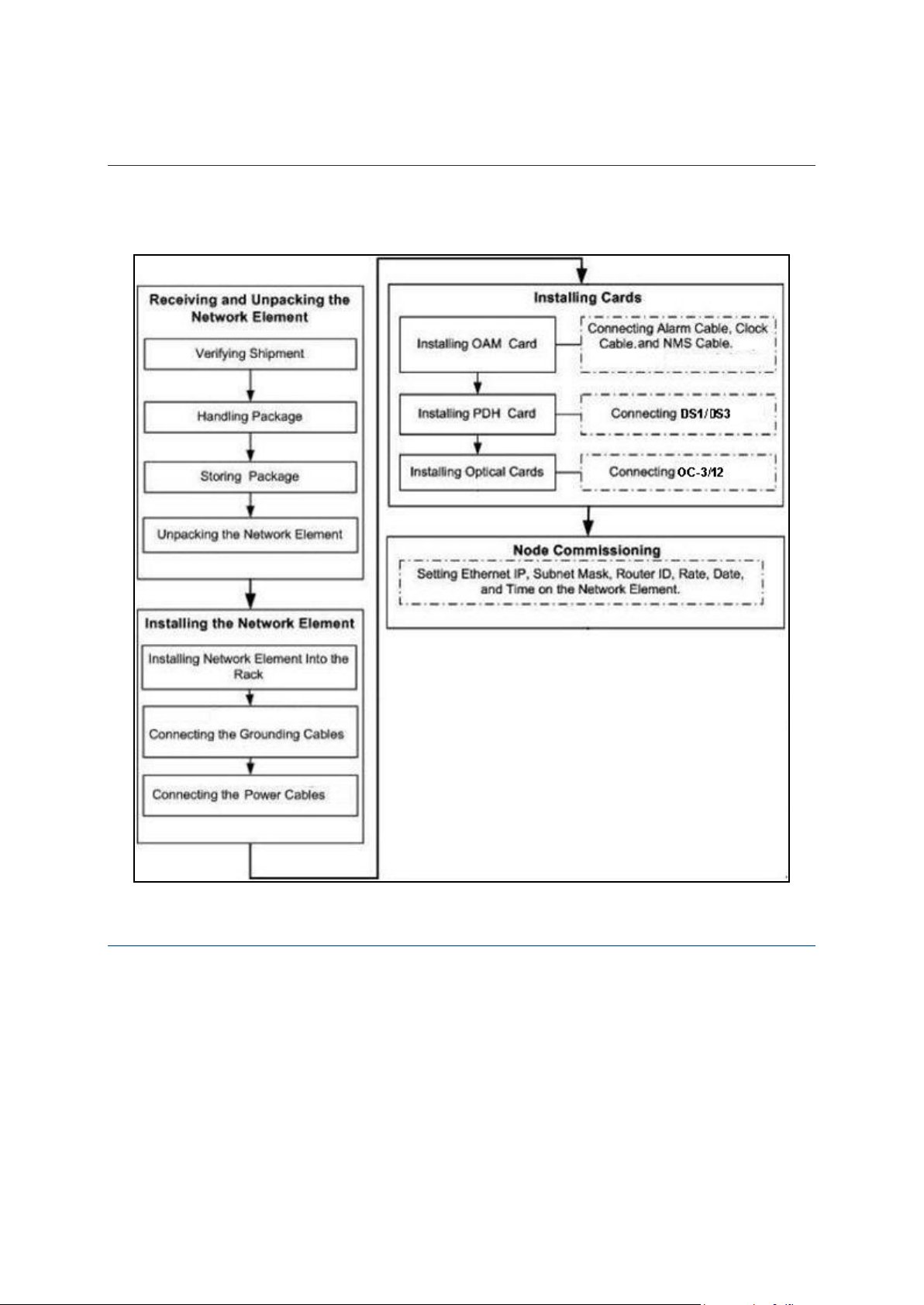
Installation and Commissioning Process Overview
Figure 1: Installation and Commissioning Process Flow
The flowchart below shows the installation and commissioning process.
Understanding Installation Procedure
Installation procedure comprises of:
Receiving and unpacking the network element
Installing the chassis on the rack
Cabling of 48 V earthing cable and DC power supply cables.
18

Chapter 2 Understanding Installation, Commissioning, and Testing Process
Understanding Commissioning Procedure
The commissioning is the formal hand over of the operational and maintenance responsibility for
the end-product from the vendor to the operator. The process comprises of Operation and
Performance qualification and includes environment compliance checks, verification of personnel
protection equipment and qualification of containment systems.
19


This chapter provides important safety guidelines that you must follow for personnel safety and
Specification
Standard Compliance
EMI / EMC
FCC Part-15, Subpart B, Class-A
ICES-003, Class-A
EN 300386
EN 55022 Class-A / CISPR-22 Class-A
EN 55024 / CISPR-24
EN 61000-3-2 and EN 61000-3-3 (applicable to AC power supply
model only)
Chapter 3
Observing Safety Guidelines
IN THIS CHAPTER
Safety Standard Compliance .......................................................................... 21
Safety Recommendations ............................................................................... 22
General Site Requirements ............................................................................. 23
Working with Power Supply Unit ................................................................. 24
Preventing Damage to Card and Pluggable Module .................................. 25
Dissipating Static Electricity .......................................................................... 26
Controlling Equipment Environment .......................................................... 27
Using Optical Fibers ....................................................................................... 27
to operate the equipment correctly. It also describes about the site environment and instructions
to be followed during site preparation and network element rack configuration. You must read
and follow all the precautionary procedures before starting to operate the network element.
Safety Standard Compliance
The network element complies with the following safety standards:
21

iPasolink250 Installation and Commissioning Guide Document ID: 141-DOC000008-E
Specification
Standard Compliance
Safety
Certified for CB – Scheme
IEC 60950 / EN 60950
UL 60950
CAN/CSA-C22.2 No. 60950
Laser Safety
IEC 60825-1 / EN 60825-1
IEC 60825-2 / EN 60825-2
21 Code of Federal Regulations (CFR)1040
Safety Recommendations
This section lists the safety recommendations that need to be followed for safe operation of the
network element.
General Safety Guidelines
Keep the chassis clean and dust-free before, during and after the installation.
Keep tools away from the area where you and others could fall over them.
Avoid wearing loose cloths that could get caught in the chassis. Fasten your tie or scarf and
roll up your sleeves before handling the equipment.
Wear safety glasses if you are working under any conditions that might hazardous to your
eyes.
Do not perform any action that creates a potential hazard to people or make the equipment
unsafe.
Maintaining Safety with Electricity
Follow the listed guidelines while working on equipment powered by electricity:
1. Locate the emergency power-off switch for the room in which you are working. Then, if an
electrical accident occurs, you can act quickly to turn off the power.
2. Disconnect all power by turning off the power and unplugging the power cord before:
Installing or removing a chassis
Working near power supplies
3. Do not work alone if potentially hazardous conditions exist.
4. Never assume that power is disconnected from a circuit. Always check the circuit to confirm.
5. Look carefully for possible hazards in your work area, such as cords, and missing safety
grounds. If an electrical accident occurs, proceed as follows:
Turn off the system.
22

Chapter 3 Observing Safety Guidelines
Determine if the person needs rescue breathing or external cardiac compressions,
and then take appropriate action.
Preventing Electrostatic Discharge Damage
Electrostatic discharge (ESD) can damage equipment and impair electrical circuitry. ESD damage
occurs when electronic components are improperly handled and can result in complete or
intermittent failures.
To ensure optimal electrostatic discharge protection:
Always follow ESD-prevention when removing and replacing components.
Ensure that the chassis is electrically connected to earth ground.
Wear an ESD-preventive wrist strap, ensuring that it makes good skin contact.
Connect the grounding clip to an unpainted surface of the chassis frame to safely ground
ESD voltages.
The wrist strap and cord must operate effectively to properly guard against ESD damage and
shocks. If no wrist strap is available, ground yourself by touching the metal part of the
chassis.
For safety, periodically check the resistance value of the antistatic strap, which should be
between 1 and 10 Mega Ohms (MOhm).
Site Environment
Network element can be mounted in a rack. The location of the network element, the layout of
your network element rack including wiring room is extremely important for proper system
operation. Network element placed closer to each other, inadequate ventilation, and inaccessible
panels can cause system malfunctions and shutdowns, which calls for unscheduled system
maintenance.
While planning your site layout and network element locations, consider the precautions
described in the section "
Preventive Site Configuration
on page 24" to understand how to
avoid network element failures and reduce the possibility of environmentally caused shutdowns.
If you are currently experiencing shutdowns or unusually high errors with your existing network
element, these precautions may help you isolate the cause of failures and prevent potential
problems.
General Site Requirements
This section describes the requirements your site must meet for safe installation and operation of
the system. Before installation, verify the site for readiness as per the site verification checklist
given in "Site Verification Checklist".
23
iPasolink250 Installation and Commissioning Guide Document ID: 141-DOC000008-E
Preventive Site Configuration
Take following precautions to plan an acceptable operating environment for your network
element and to avoid environmental equipment failures:
Electrical equipment generates heat. Without adequate air circulation, the ambient air
temperature might not be adequate to cool equipment to acceptable operating temperatures.
Ensure that the room in which you operate your system has proper ventilation.
Damage from static discharge can cause immediate or intermittent equipment failure. Always
follow the ESD prevention procedures to avoid damage to equipment.
An open chassis allows air leaks, which may interrupt and redirect the flow of cooling air
from internal components. Ensure that the chassis cover is secure to allow cooling air to flow
effectively from right to left within it.
CAUTION: Proper hydraulic/pneumatic material handling equipment must be used
for mounting the equipment. If the network element is heavy and the hydraulic equipment is
not available then ensure that at least two installers are at the installation site.
Configuring Equipment Racks
While planning an acceptable equipment rack configuration, ensure that:
The enclosed racks have adequate ventilation and are not overly congested.
The enclosed rack should have lowered sides and a fan to provide cooling air, since each unit
generates heat.
The rack frame does not block the intake or exhaust ports while chassis is mounted in an
open rack.
Chassis is placed at the right position into the rack, if the chassis is installed on slides.
Adequate ventilation is available for equipment at the bottom of the rack. In an enclosed rack
with a ventilation fan in the top, excessive heat generated by equipment near the bottom of
the rack can be drawn upward and intake ports of the equipment.
Baffles helps isolating exhaust air from intake air, which also helps to draw cooling air
through the chassis. The best placement of the baffles depends on the airflow patterns in the
rack. Experiment with different arrangements to position the baffles effectively.
Working with Power Supply Unit
When you install power feeds to the product input terminals or if you perform routine power
maintenance, make sure that you do the following:
Read the power procedures before you perform any function.
Use appropriate insulated tools to perform any tasks.
24
Chapter 3 Observing Safety Guidelines
The green LED continuously lit at the faceplate on the base card indicating that the card is
powered up and is functioning correctly. If the green LED on the PSU is ON, the power at the
associated feeder is present and the conditions can be assumed to be normal. Some of the
possible cases when the green LED on the base card is not ON are:
Power supply unit is damaged or non-functional.
Base card is damaged or non-functional.
Feeder low voltage or power failure
Over-current failure
Blown fuse in the power supply unit due to the reverse polarity condition at the input
terminals.
The circuit breaker on the power supply unit is an electronic circuit breaker that cuts off the
power to the card on over-current condition.
RISK OF ELECTRICAL SHOCK: The battery feeds can be at a high enough
potential to constitute a shock hazard. Use the appropriate insulated tools when working with
power unit.
RISK OF PERSONAL INJURY, ENERGY HAZARD: The battery feeds are capable
of supplying very high current which, during an unintentional short, can cause burns. Use the
appropriate insulated tools when working with power unit.
Preventing Damage to Card and Pluggable Module
In this section, the generic term 'card' is used to refer to cards or pluggable modules as applicable.
These cards are shipped to the customer premises in shielded containers. All cards are subject to
damage by rough handling or by electrostatic discharges.
NOTE: Follow precautions for handling electrostatic sensitive devices.
While handling, installing, storing or replacing cards, take the following necessary precautions:
Wear an antistatic wrist-strap, a heel grounder, or another personal grounding device before
you remove a module from its package or from the shelf.
Follow installation and removal procedures for each module. Make sure to understand and
perform each precautionary message in these procedures (for example, opening or closing the
latches of the card simultaneously).
Do not touch the solder side of the module, the pin connector, or the components.
25

iPasolink250 Installation and Commissioning Guide Document ID: 141-DOC000008-E
Inspect all pin connectors for damage before using them on each module.
Inspect each module for damage before inserting the component into the shelf.
Store uninstalled cards separately in a shielded box.
Do not stack cards on or against each other.
Do not force cards into their packaging material.
Do not store several cards in the same container.
Allow each module to reach room temperature before you insert the module into the shelf.
When not in use store pluggable modules in their protective static-dissipative containers to
prevent damage to the exposed connector terminals.
Leave spare cards in the original shielded containers until you need the cards.
To prevent damage to cards in storage, follow procedures that prevent accumulation of dirt
or dust on the pin connectors and damage to the printed-circuit board or its components
wrapage. This situation is typical for printed-circuit boards stored in areas where the humidity
can exceed 95% and the temperature can exceed 70 °C.
While transporting cards, pack each module in its original shielded container and padding, or
in an electrostatically shielded bag. In case the original packing material is lost, place the
module in a shielded bag and use another container with sufficient padding.
Air filters have to be replaced once in 6 months.
Dissipating Static Electricity
The static electricity level in your body increases when you move around or come into contact
with other charged surfaces. Excessive levels of static electricity can damage the equipment. You
must either wear a properly functioning heel grounder (that attaches to your leg and foot) and/or
an antistatic wrist-strap, or another grounding device when you work on any of the following:
Network element chassis (including the metal frame and cover)
Cables connected to cards
Cards
Any one of the previously mentioned grounding devices dissipates electrostatic charges to the
ground quickly and safely. Use grounding devices correctly to eliminate the ESD threat you pose
to the equipment.
When you wear an antistatic wrist-strap or a heel grounder, you must make sure the grounding
straps are in contact with a moist part of your skin. Connect the grounding cord to the grounding
plug on a grounded fixture of the product you are working on, such as the shelf ESD jack,
grounded fixtures are accessible on most of the products.
26

Chapter 3 Observing Safety Guidelines
CAUTION: Heel grounders or similar worn footwear attachments work when the
floor is designed to dissipate static electricity. Also check for the ESD foot wear attachment
connectivity to ground using suitable ESD tester. If the properties of the floor are unknown
or in doubt, use a wrist-strap and make sure it is connected to a piece of electrostatic discharge
(ESD) grounding equipment before proceeding with any maintenance or installation activity.
The following guidelines provide an optimal electrostatic discharge protection:
Install bays on conductive floor coverings.
Provide conductive shoes, antistatic wrist-straps and heel grounders to all personnel working
on the equipment.
Maintain local environmental conditions so that relative humidity around equipment to be
serviced is in excess of 20% (preferably higher than 40%). This lowers the threat of
developing damaging electrostatic levels.
Implement an ESD training and control program that educates personnel on the hazards of
ESD and simple mitigation procedures that can easily be applied.
Controlling Equipment Environment
The maximum operational long-term ambient temperature of the system location is 40 °C. A
temperature above 40 °C is permissible (according to ETSI EN 300 019-1-3 V2.1.2 Edition
2003-04 for Environmental Class 3.1: Temperature controlled locations and ETSI EN 300 019-23 V2.1.2 for Environmental Class T3.1 and T3.1E: Temperature controlled locations) provided
the probability of occurrence is less than 1%. A temperature of 50 °C is permissible but the
duration should not exceed 72 continuous hours.
Using Optical Fibers
Optical fibers are either single mode or multiple modes. The information in the following
sections applies to all optical fibers.
Handling Optical Fibers
When handling optical fibers:
Wear safety glasses when you install optical fibers.
Do not look into the opening of an optical fiber, or the opening of an optical fiber
connector, if the optical fiber is active or the unit has the power turned on.
Avoid direct exposure to optical fiber ends or optical connector ends where you can access
the laser signal directly.
27
iPasolink250 Installation and Commissioning Guide Document ID: 141-DOC000008-E
LASER RADIATION EXPOSURE RISK: Do not look directly into the optical beam.
Invisible light can severely damage your eyes. Keep all optical connectors capped.
Splicing Optical Fibers
Before looking at a spliced optical fiber with a magnifier:
Power off all laser sources to the optical fiber or disconnect the remote optical fiber end
from the laser sources before you start splicing. The laser sources can be in a central office,
on subscriber premises, or in a remote location.
Disconnect all optical test sets from the optical fiber before you start splicing. The
connections can be local or remote.
Use only the optical instruments approved by your company.
When splicing optical fibers:
Clean your hands after you handle optical fibers. Small pieces of glass are not always visible
and can damage your eyes.
Do not handle pieces of optical fiber with your fingers. Use tweezers (preferably non
metallic) or adhesive tape to lift and discard any loose optical fiber ends.
Wear rubber gloves when you clean optical connectors. The gloves prevent direct contact
with the isopropyl alcohol and prevent contamination of the ferrules with skin oils.
Place all optical fiber clippings in a plastic container provided for that purpose.
Handle optical fibers with caution. Place the optical fibers in a safe location during
installation.
Protect all optical fiber connectors with clean dust caps at all times.
Follow the manufacturer instructions when you use an optical test set. Incorrect calibration
or control settings can create hazardous levels of radiation.
EYE INJURY RISK: If you have a piece of a glass in your eye, get medical assistance
immediately.
Repairing Optical Fibers
When an accidental break occurs in the optical fiber:
Report the location of the damaged optical fiber to both the central office and the field repair
personnel.
Power-off all laser sources to the optical fiber or disconnect the remote optical fiber end
from the laser sources. The laser sources can be in a central office, on subscriber premises, or
in a remote location.
28

Chapter 3 Observing Safety Guidelines
29

 Loading...