

Page 1

Proprietary Notice and Liability Disclaimer
The information disclosed in this document, including all designs and related materials, is the
valuable property of NEC Computer Systems Division, Packard Bell NEC, Inc. (hereinafter
“NECCSD”) and/or its licensors. NECCSD and/or its licensors, as appropriate, reserve all patent,
copyright and other proprietary rights to this document, including all design, manufacturing,
reproduction, use, and sales rights thereto, except to the extent said rights are expressly granted to
others.
The NECCSD product(s) discussed in this document are warranted in accordance with the terms of
the Warranty Statement accompanying each product. However, actual performance of each such
product is dependent upon factors such as system configuration, customer data, and operator
control. Since implementation by customers of each product may vary, the suitability of specific
product configurations and applications must be determined by the customer and is not warranted
by NECCSD.
To allow for design and specification improvements, the information in this document is subject to
change at any time, without notice. Reproduction of this document or portions thereof without prior
written approval of NECCSD is prohibited.
FaxFlash is a service mark of NEC Computer Systems Division (NEC CSD), Packard Bell NEC, Inc.
NEC is a registered trademark of NEC Corporation, used under license.
ENERGY STAR is a U.S. registered mark.
All other product, brand, or trade names used in this publication are the trademarks or registered trademarks of their
respective trademark owners.
First Printing — August 1998
Copyright 1998
NEC Computer Systems Division
Packard Bell NEC, Inc.
1 Packard Bell Way
Sacramento, CA 95828-0903
All Rights Reserved
Page 2

Preface
This service and reference manual contains the technical information necessary to set up
and maintain the NEC Versa
computers.
The manual also provides hardware and interface information for users who need an
overview of the system design. The manual is written for NEC-trained customer engineers,
system analysts, service center personnel, and dealers.
The manual is organized as follows:
Section 1, System Overview, provides an overview of the hardware and interface
components.
Section 2, System Configuration and Setup, provides information on setup and how to
operate the docking station.
Section 3, Disassembly and Reassembly, provides detailed instructions on how to
disassemble and reassemble the docking station.
Section 4, System Board Layout and Board Connectors, shows the system boards and the
board connectors.
®
Dock, for use with the NEC Versa LX and SX notebook
Section 5, Illustrated Parts Breakdown, shows the Illustrated Parts Breakdown (IPB) and
corresponding part numbers.
Section 6, Preventive Maintenance, lists general docking station preventive maintenance
procedures.
Section 7, Troubleshooting, lists troubleshooting procedures as well as helpful servicing
hints.
Section 8, Support, provides information as to how to contact NEC CSD for service
information, technical support, product information and ordering information from
FaxFlash.
Section 9, Specifications, lists physical specifications.
An Index is included for convenience.
Preface v
Page 3

Abbreviations
A ampere
AC alternating current
AT advanced technology
(IBM PC)
BBS Bulletin Board Service
BCD binary-coded decimal
BCU BIOS Customized Utility
BIOS basic input/output system
bit binary digit
BUU BIOS Upgrade Utility
bpi bits per inch
bps bits per second
C capacitance
C centigrade
Cache high-speed buffer storage
CAM constantly addressable
memory
CAS column address strobe
CD/ROM compact disk-ROM
CG character generator
CGA Color Graphics Adapter
CGB Color Graphics Board
CH channel
clk clock
cm centimeter
CMOS complementary metal oxide
semiconductor
COM communication
CONT contrast
CPGA ceramic pin grid array
CPU central processing unit
DAC digital-to-analog converter
DACK DMA acknowledge
DC direct current
DIP dual in-line package
DLAB Divisor Latch Address bit
DMA direct memory access
DMAC DMA controller
DOS disk operating system
DRAM dynamic RAM
ECC error checking and correction
EDO extended data output
EGA Enhanced Graphics Adapter
EPROM erasable and programmable
ROM
EVGA Enhanced Video Graphics
Array
F Fahrenheit
FAX facsimile transmission
FCC Federal Communications
Commission
FG frame ground
FM frequency modulation
FP fast page
FRU field-replaceable unit
GB gigabyte
GND ground
HEX hexadecimal
HGA Hercules Graphics Adapter
Hz hertz
IC integrated circuit
ID identification
IDE intelligent device electronics
IDTR interrupt descriptor table
register
in. inch
INTA interrupt acknowledge
IPB illustrated parts breakdown
IR infrared
IRR Interrupt Request register
ISA Industry Standard
Architecture
ISR In Service register
I/O input/output
vi
Page 4

IPC integrated peripheral
controller
ips inches per second
IRQ interrupt request
K kilo (1024)
k kilo (1000)
KB kilobyte
kg kilogram
kHz kilohertz
lb pound
LED light-emitting diode
LSB least-significant bit
LSI large-scale integration
M mega
mA milliamps
max maximum
MB megabyte
MDA Monochrome Display Adapter
MFM modified frequency
modulation
MHz megahertz
mm millimeter
ms millisecond
MSB most-significant bit
NASC National Authorized Service
Center
NC not connected
NMI Non-maskable Interrupt
ns nanosecond
NSRC National Service Response
Center
PAL programmable array logic
PCB printed circuit board
PCI Peripheral Component
Interconnect
PDA personal digital assistant
PFP plastic flat package
PIO parallel input/output
pixel picture element
PLCC plastic leaded chip carrier
PLL phase lock loop
p-p peak-to-peak
PPI programmable peripheral
interface
PROM programmable ROM
QFP quad flat pack
RAM random-access memory
RAMDAC RAM digital-to-analog
converter
RAS row address strobe
RGB red green blue
RGBI red green blue intensity
ROM read-only memory
rpm revolutions per minute
R read
RTC real-time clock
R/W read/write
S slave
SCSI Small Computer System
Interface
SG signal ground
SIMM single inline memory module
SPM standard page mode
SRS Sound Retrieval System
SVGA Super Video Graphics Array
SW switch
TAC Technical Assistance Center
TSC Technical Support Center
TTL transistor/transistor logic
tpi tracks per inch
USB universal serial bus
V volt
Vac volts, alternating current
Vdc volts, direct current
VESA video electronics standards
association
VFC VESA-compliant feature
connector
VGA Video Graphics Array
VRAM video RAM
W watt
W write
vii
Page 5

Contents
Preface .....................................................................................................................................v
Abbreviations......................................................................................................................... vi
1 Introducing the NEC Versa Dock
Carton Contents.....................................................................................................................1-2
NEC Versa Dock Features.....................................................................................................1-3
Front and Top..............................................................................................................1-3
Left Side ......................................................................................................................1-6
Right Side....................................................................................................................1-7
Back............................................................................................................................ 1-8
The Right Environment.......................................................................................................... 1-9
Operating Environment................................................................................................1-9
Storage Environment ................................................................................................... 1-9
2 System Configuration and Setup
Setting Up Software...............................................................................................................2-2
Updating the BIOS ......................................................................................................2-2
Installing Drivers.........................................................................................................2-4
Installing the Online User’s Guide ............................................................................... 2-5
Docking and Undocking ........................................................................................................ 2-6
Connecting the Power Cable........................................................................................ 2-6
Preparing the NEC Versa for Docking .........................................................................2-7
Docking the NEC Versa...............................................................................................2-9
Locking the NEC Versa............................................................................................. 2-13
Undocking the NEC Versa.........................................................................................2-15
Emergency Undocking............................................................................................... 2-17
Installing Options and Connecting Devices..........................................................................2-18
Installing Devices in the File Bays.............................................................................2-19
Installing Devices in the File Bays.............................................................................2-19
Installing PCI Cards...................................................................................................2-32
Installing PC (PCMCIA) Cards..................................................................................2-34
Connecting External Devices.....................................................................................2-35
3 Disassembly and Reassembly
Required Tools and Equipment.............................................................................................. 3-2
Disassembly ..........................................................................................................................3-2
Preparation for Disassembly ........................................................................................3-3
Removing Trays, Panels and Covers............................................................................3-3
Disconnecting the Cables from the Motherboard..........................................................3-6
Removing Device Brackets..........................................................................................3-7
Back Cover, Left and Right Sides, and Top Cover .......................................................3-8
Docking Connector Board, PCI Housing, and Power Supply........................................3-9
Docking Tray Assembly and Motor Assembly...........................................................3-12
Main Board Assembly ...............................................................................................3-13
Reassembly ......................................................................................................................... 3-14
Contents iii
Page 6

4 System Board Layout
Main Board ...........................................................................................................................4-2
LED Board............................................................................................................................4-2
PCI Expansion Board.............................................................................................................4-2
5 Illustrated Parts Breakdown
NEC Versa Dock Illustrated Parts Breakdown........................................................................5-2
Parts List...............................................................................................................................5-3
6 Preventive Maintenance
Precautions............................................................................................................................ 6-2
Battery Charging ...................................................................................................................6-2
Routine Care..........................................................................................................................6-3
Cleaning the Versa Dock Interior...........................................................................................6-3
Protecting the Disk Drives ..................................................................................................... 6-4
7 Troubleshooting
Quick Troubleshooting ..........................................................................................................7-2
Helpful Questions..................................................................................................................7-4
8 Getting Services and Support
Services and Support Contact Information .............................................................................8-2
NEC NOW............................................................................................................................ 8-3
NEC CSD Web Site ...............................................................................................................8-3
NEC CSD FTP Site ...............................................................................................................8-4
NEC CSD FaxFlash Service...................................................................................................8-4
Email/Fax to Support Services...............................................................................................8-5
NEC CSD Bulletin Board ...................................................................................................... 8-6
NEC CSD Support Services...................................................................................................8-7
NEC CSD Customer Assistance Center..................................................................................8-8
Versa Laptop Fulfillment Hotline...........................................................................................8-8
9 Specifications
Features.................................................................................................................................9-2
Input/Output Facilities...........................................................................................................9-2
Expansion Capabilities...........................................................................................................9-3
Indicator LEDs......................................................................................................................9-3
Power Supply ........................................................................................................................9-3
Power Cables .........................................................................................................................9-4
Dimensions............................................................................................................................ 9-4
Environmental Requirements................................................................................................. 9-4
Glossary
Index
iv Contents
Page 7

1
Introducing the NEC Versa Dock
n Carton Contents
n NEC Versa Dock Features
n The Right Environment
Page 8
The NEC Versa Dock lets you maximize your NEC Versa LX and SX
capabilities without minimizing portability. Connect an external monitor and
keyboard to the ports on the back of the NEC Versa Dock, install your
CD-ROM reader in the optional NEC Versa Dock VersaBay III adapter kit,
attach your joystick to the MIDI/Game port, and you're ready to work hard or
play! Undock the NEC Versa from the NEC Versa Dock and you're ready for
the road.
This chapter introduces NEC Versa Dock features, guides you to choosing the
correct environment.
Carton Contents
Unpack and check the contents of the NEC Versa Dock carton.
Be sure you have the hardware components shown in the following figure and
that they are in good condition. If anything is damaged or missing, contact your
dealer immediately.
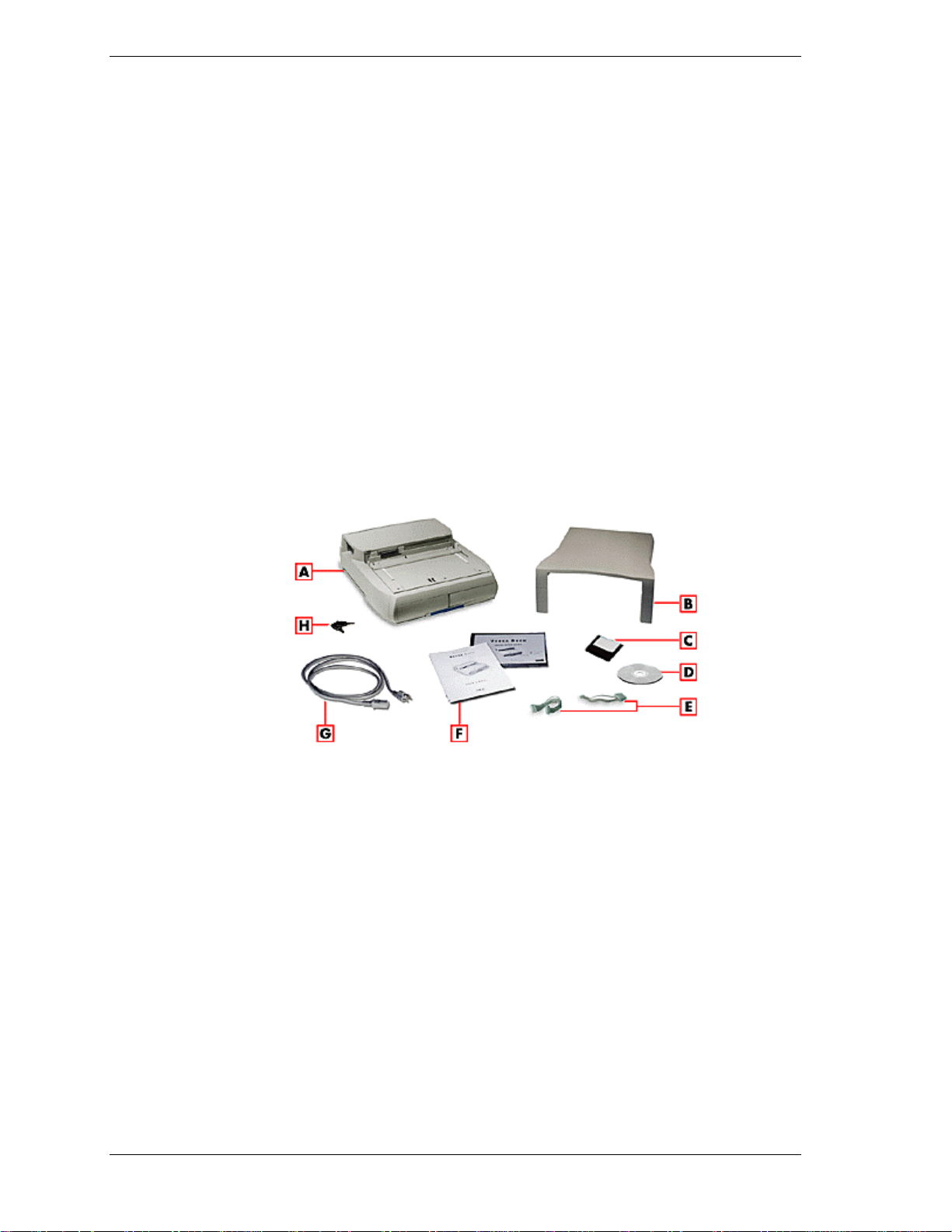
Carton Contents
A - NEC Versa Dock B - CRT base C - BIOS update diskette
D - Software Setup CD E - IDE power cables F - User documentation
G - AC power cable H - NEC Versa Dock keys
n NEC Versa Dock — provides many features to expand your NEC Versa
capabilities. These features are described in detail in this chapter.
n CRT Base — supports an external monitor that weighs up to 55 lb (25
kg).
n BIOS update diskette.
n NEC Versa Dock Software Setup CD.
n Two extra power cables for the installation of optional IDE devices.
1-2 Introducing the NEC Versa Dock
Page 9
n User Documentation — introduces you to the NEC Versa Dock and
guides you through initial docking and setup.
n AC Power Cable — allows you to connect your NEC Versa Dock to AC
power.
Always use the power cable that ships with the NEC Versa Dock. If you
need to replace the cable, follow these standards:
In North America, the cable should be rated for 120 volts (V), 7
amps(A). The plug is a NEMA 5-15P. Use an SVT or SJT 18/3 AWG
cable that is less than 15 feet (4.5 m) long. Use connector type
IEC320.
In Europe, the cable should be rated for 230 V (220-240 V), 10A. The
plug is country-specific. Use an H05VV-F or H05VVH2-F cable that
is less than 15 feet (4.5 m) long. Use connector type EN60320.
n NEC Versa Dock Keys.
NEC Versa Dock Features
NEC Versa Dock features are found on all sides of the unit. To become familiar
with these features, read each of the following sections.
Front and Top
The following figure shows the features found on the front and top of the NEC
Versa Dock. Descriptions of these features follow the figure.
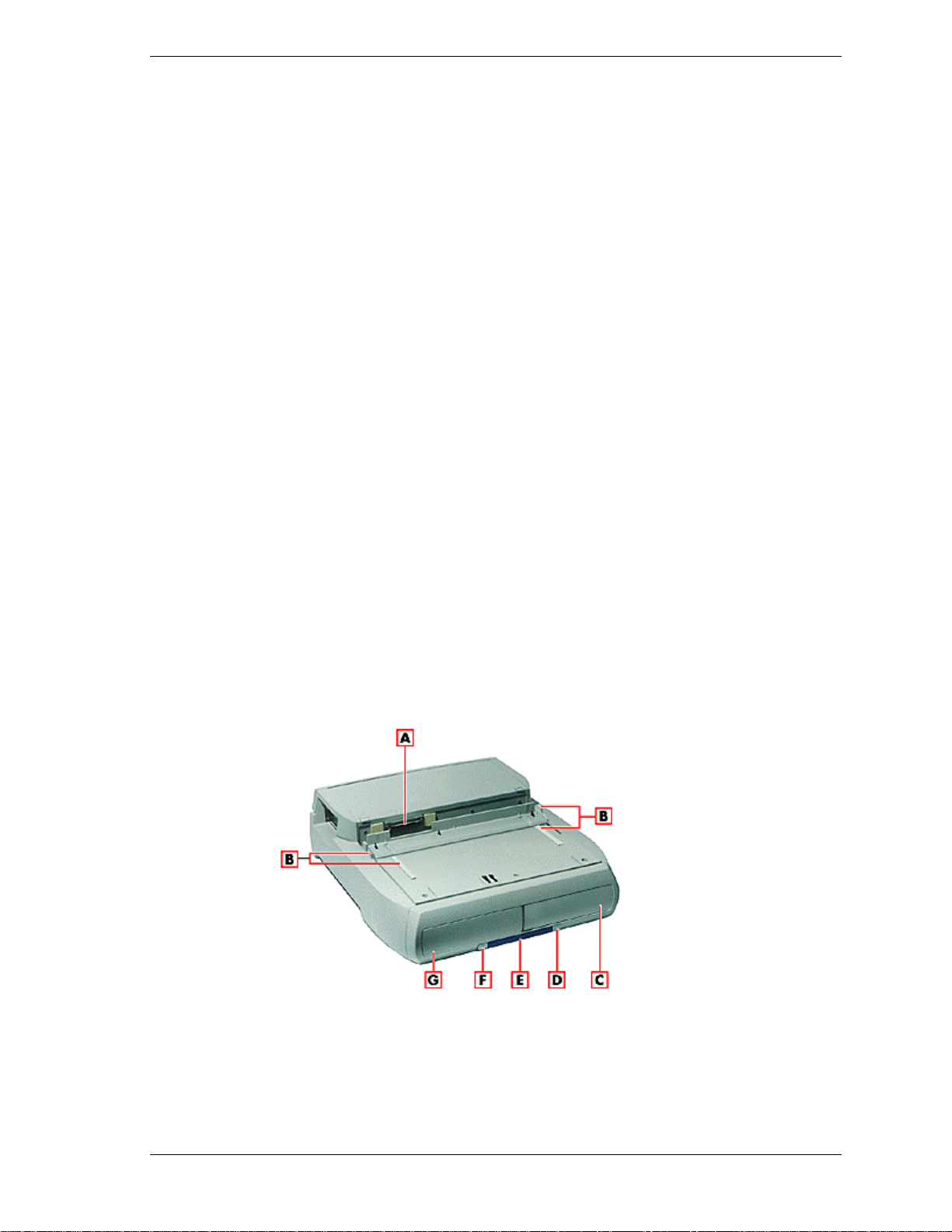
Front and top features
A - Docking connector B - Docking guides C - Right file bay
D - Power button E - Status LEDs F - Dock/Undock button
G - Left file bay
Introducing the NEC Versa Dock 1-3
Page 10
n Docking Connector — Fits the expansion port on your NEC Versa to
allow for docking.
n Docking Guides — Ensure that your NEC Versa is aligned properly for
docking. These guides provide positioning for docking with the monitor
stand in place.
n Two File Bays — Allows you to install IDE file devices in your NEC
Versa Dock.
The left file bay supports any 5.25-inch IDE device (like a tape drive,
hard disk drive, or SuperDisk drive.) It also supports 3.5-inch IDE
devices with a 3.5-inch Universal Installation Kit.
The right file bay is identical to the left file bay, with the added
versatility that allows you to install the optional VersaBay III Adapter
Kit. With the VersaBay III Adapter kit installed, you can use any of
your VersaBay III options in the file bay.
n Power Button — Allows you to power on and off the NEC Versa LX or
SX notebook computer while docked on the NEC Versa Dock.
n Status LEDs — LEDs on the front of the unit inform you of the docking
status, keylock status, IDE drive access, diskette drive access, and battery
charge status (for a battery installed in the optional VersaBay III Adapter
Kit). LEDs are shown in the following figure and LED states are
described after the figure.
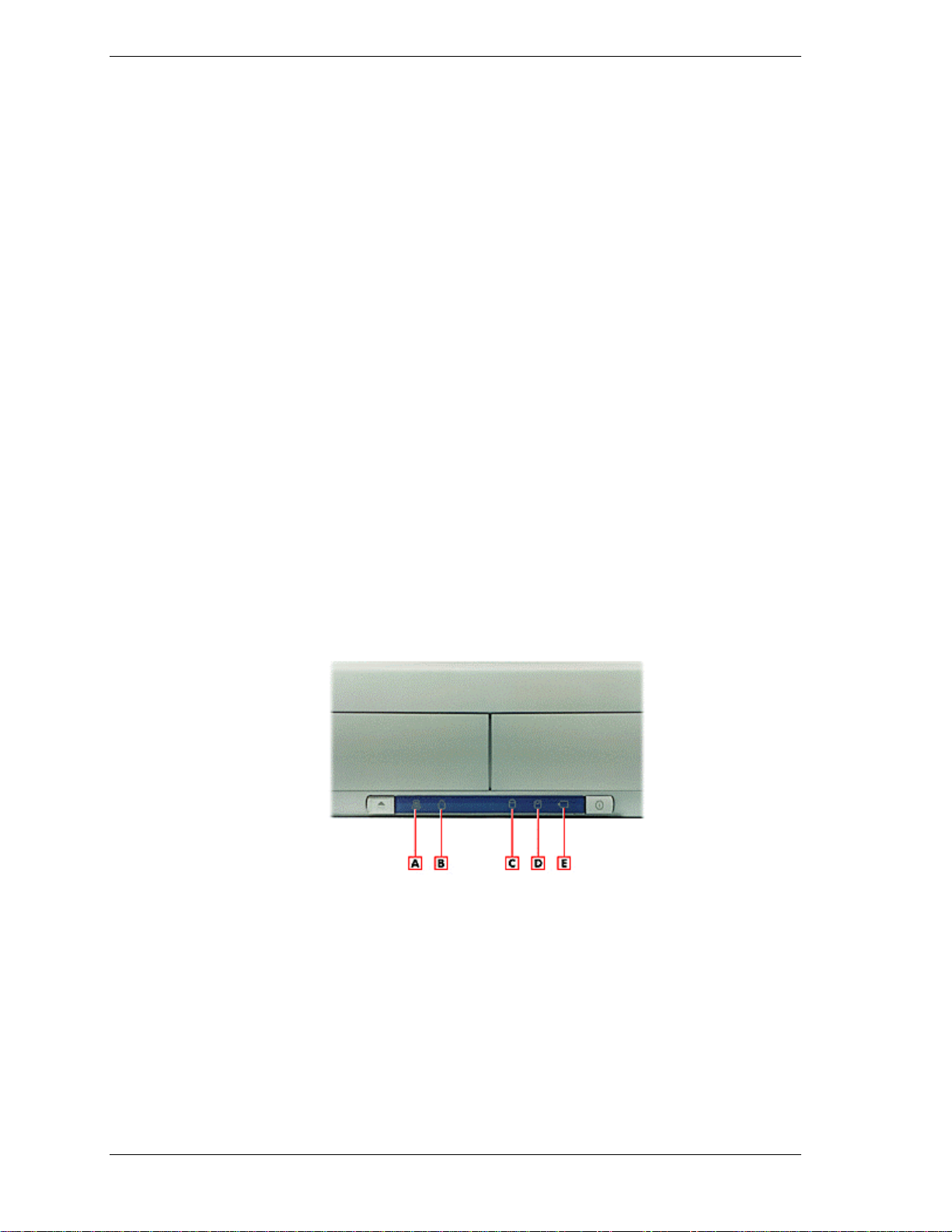
Status LEDs
A - Docking status LED B - Keylock status LED C - IDE access LED
D - Diskette drive access LED E - Battery charge status LED
1-4 Introducing the NEC Versa Dock
Page 11

Hot docking and hot undocking is supported with Plug-andPlay operating systems, such as Windows 95. Before hot
undocking, the docking/undocking button must be pressed
or you must select Eject PC from the Windows 95 Start
button. May not be supported on all systems.
Docking Status – lights as follows:
– Steady Yellow – AC power is on, the keylock switch is in the
Normal position, and the NEC Versa Dock is ready for docking.
– Steady Green – The NEC Versa is docked on the NEC Versa Dock
and is either powered on or in Standby mode.
– Fast Blinking Amber – A docking or undocking error has occurred or
the docking tray is in the wrong position for the system.
– Off – AC power is on, the keylock is in the Manual or Locked
position, and either no NEC Versa is docked or the NEC Versa is
docked and powered off.
Keylock Status – Lights as follows:
– Off – No NEC Versa is docked.
– Steady Amber – The NEC Versa is docked but not locked on the
NEC Versa Dock. The key is in either the Normal position with the
notebook turned off, or in the Manual position with the notebook on
or off.
– Steady Yellow – The NEC Versa is locked onto the NEC Versa Dock
through software. The key is in the Normal position and the NEC
Versa is on.
– Steady Green – The NEC Versa is physically locked onto the NEC
Versa Dock. The key is in the Lock position with notebook power on
or off.
IDE Drive Access – lights as follows to indicate access to an IDE device
such as a CD-ROM, hard disk or SuperDisk drive installed in an NEC
Versa Dock file bay, an optional VersaBay III Adapter Kit, or in the
NEC Versa.
– Off – No IDE device is being accessed.
– Green – The NEC Versa is accessing the IDE drive.
Diskette Drive Access – Lights as follows to indicate access to a floppy
disk drive installed in the NEC Versa notebook computer only.
– Off – No diskette drive is being accessed.
Introducing the NEC Versa Dock 1-5
Page 12
Left Side
– Green – The NEC Versa is accessing the diskette drive.
Battery Charge Status – Lights as follows to indicate the battery charge
to a secondary battery pack installed in the optional VersaBay III
Adapter Kit.
– Steady Green – The battery installed in the optional VersaBay III
Adapter Kit is being charged. You can charge the battery whether the
NEC Versa Dock is powered on or off or is in Standby mode. You
can also charge the battery in the optional VersaBay III Adapter Kit
when no system is docked in the NEC Versa Dock. The NEC Versa
Dock must be connected to an AC power source to charge the battery
pack.
– Off – The installed battery is fully charged, or no battery is installed.
n Docking/Undocking Button — Initiates the automatic sequence for
docking or undocking your system if the keylock is in the normal
position.
Features found on the left-hand side of the NEC Versa Dock are shown in the
following figure. Features are described after the figure.
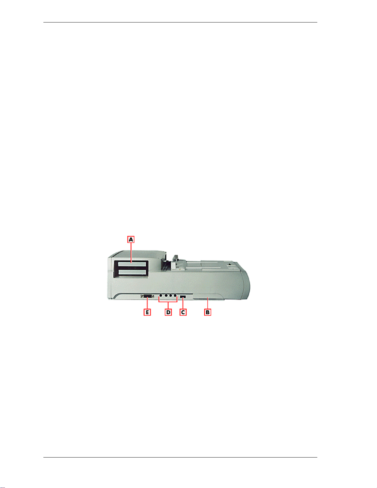
Left side features
A - PCI external access B - Height lever C - Volume control knob
D - Audio ports E - MIDI/Game port
n PCI External Access — Gives you access to external ports, connectors,
switches and indicators on installed PCI cards.
n Height Adjustment Lever — Adjusts the height on the docking tray to
match the height of your system. To access the lever, pull the door open
by the slot.
n Volume Control — Gives you control over the volume of external
speakers or headphones attached to the NEC Versa Dock.
1-6 Introducing the NEC Versa Dock
Page 13

n Audio Ports — Connects external audio devices including a microphone,
headphones, or speakers. You can also connect other audio devices to use
as an output device or input source.
n MIDI/Game Port — Supports MIDI/Game devices, such as a joystick or
MIDI keyboard.
Introducing the NEC Versa Dock 1-7
Page 14
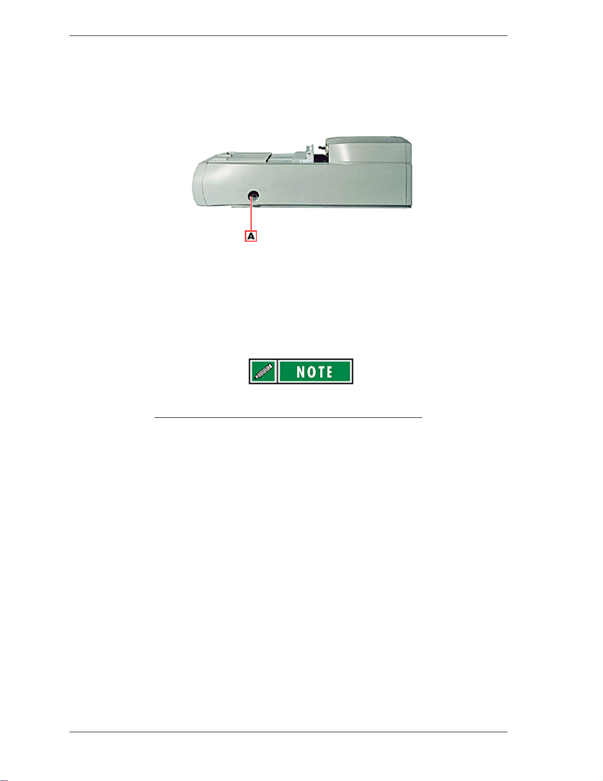
Right Side
The keylock switch on the right side of the NEC Versa Dock is shown in the
following figure. A description follows the figure.
Right side feature
A - Keylock switch
n Keylock switch — Provides three settings that let you control NEC Versa
removal. An alarm sounds if someone tries to remove the NEC Versa
while it is locked onto the NEC Versa Dock, even if the NEC Versa Dock
is powered off or is disconnected from AC power.
Motorized docking is only enabled when the keylock switch
is in the full upright position.
Locked – Prevents the NEC Versa from being removed from the NEC
Versa Dock. You must use the key to unlock the unit before removing
the NEC Versa.
Normal – (Default position). Allows you to motorize dock or undock
the NEC Versa. Set the keylock to this position for normal use. To
prevent electrical damage, manual undocking is not allowed when the
keylock is in this state.
Manual – Allows you to remove the NEC Versa by hand. Use the
unlocked position for emergency undocking only. Otherwise, use the
Normal lock setting for normal use and the Locked setting to
physically secure your system to the NEC Versa Dock.
If no computer is docked and the keylock is in the Locked position,
no one else can use their computer with the NEC Versa Dock. The
key can only be removed from the system while the keylock is in the
Locked position.
1-8 Introducing the NEC Versa Dock
Page 15
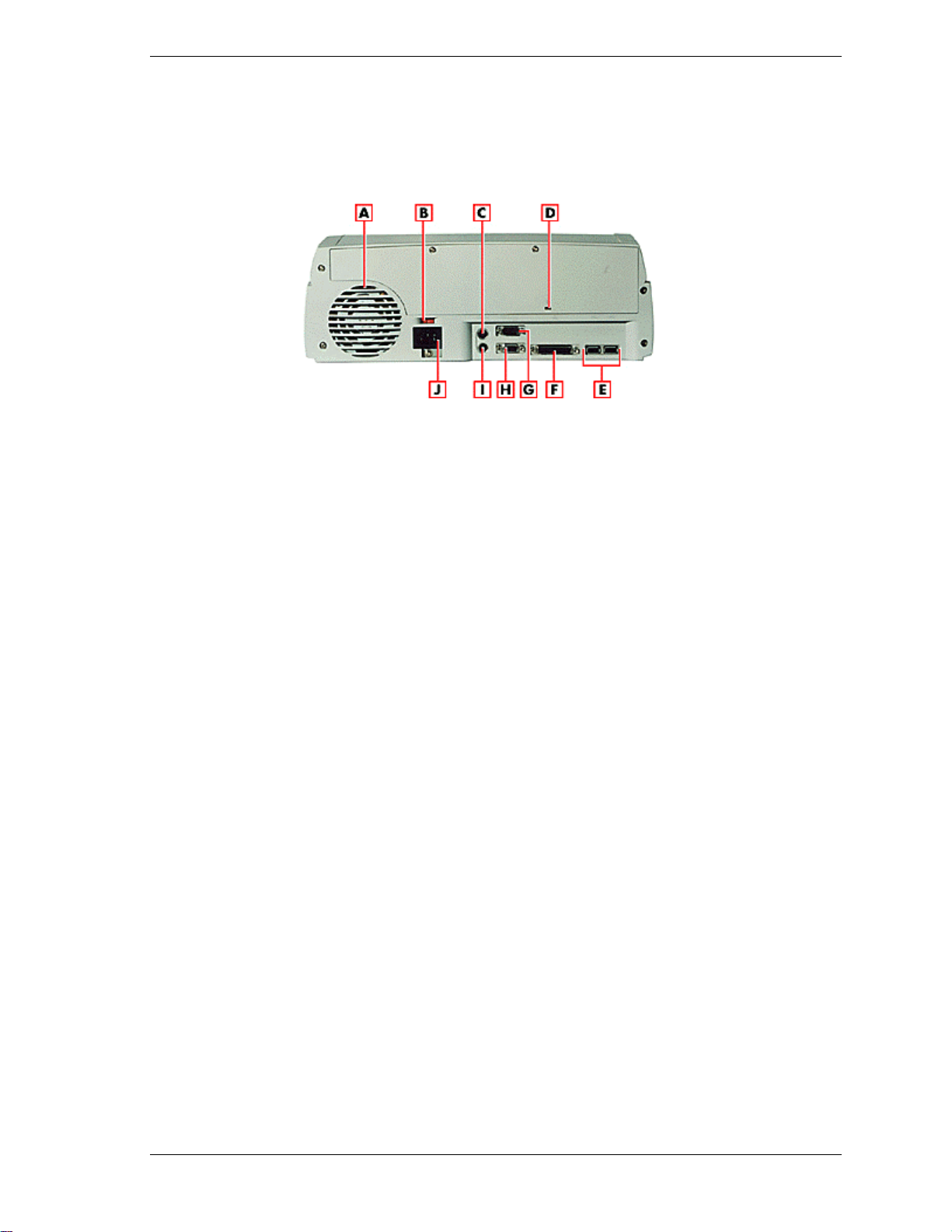
Back
Features on the back of the NEC Versa Dock are shown in the following figure.
Descriptions follow the figure.
Back features
A - Fan assembly B - Voltage selector switch C - Keyboard port
D - Kensington lock port E - USB ports F - Parallel port
G - Serial port H - Monitor port I - Mouse port J - AC power port
n Fan Assembly — Provides proper cooling for the power supply that
regulates power in the NEC Versa Dock. Keep the fan assembly clear of
obstructions to ensure proper cooling.
n Voltage Selector — Allows you to choose from 115 or 230 Volts.
n PS/2-style Keyboard Port — Allows you to connect an external keyboard
to the NEC Versa Dock.
n Kensington Lock Port — Allows you to secure your NEC Versa Dock
using an optional Kensington Lock.
n USB Ports — Allows you to connect Universal Serial Bus devices to the
NEC Versa Dock.
n Parallel Port — Allows you to connect a parallel device to the NEC Versa
Dock.
n Serial Port — Allows you to connect a serial device to the NEC Versa
Dock.
n External Monitor Port — Allows you to connect an external monitor to
the NEC Versa Dock. (You may need to press Fn-F3 to get an image on
the external monitor. See your NEC Versa User’s Guide for function key
combinations.)
n PS/2-style Mouse Port — Allows you to connect an external mouse to the
NEC Versa Dock.
n Power Port — Allows you to connect the NEC Versa Dock to AC power.
Introducing the NEC Versa Dock 1-9
Page 16

The Right Environment
Before setting up the NEC Versa Dock, find a good location for its use. Here are
some guidelines.
n Choose an area close to a wall outlet that is easily accessible.
n Select a flat, sturdy surface, like a desktop or table, so you have access to
the front, back, and sides of the unit.
n Choose an area away from extreme temperatures, direct sunlight,
excessive dust, vibration, shock or moisture.
Operating Environment
Use the NEC Versa Dock in a location that meets the following environmental
conditions:
n Temperature: 41°F to 95°F (5°C to 35°C)
n Humidity: 20% to 80% (non-condensing)
Storage Environment
Store the NEC Versa Dock in a location that meets the following conditions:
n Temperature: –4°F to 122°F (–20°C to 50°C)
n Humidity: 15% to 85% (non-condensing)
1-10 Introducing the NEC Versa Dock
Page 17

2
System Configuration and Setup
n Setting Up Software
n Docking and Undocking
n Installing Options and Connecting Devices
Page 18

Setting Up Software
Before docking the NEC Versa in the NEC Versa Dock, be sure to prepare your
NEC Versa notebook computer for use in the NEC Versa Dock. This involves
three procedures.
n Flashing the NEC Versa notebook computer’s BIOS, using the correct
BIOS Update for your NEC Versa.
n Installing the drivers on the NEC Versa notebook computer, using the
NEC Versa Dock Software Setup CD.
n Installing the Online User Guide using the NEC Versa Dock Software
Setup CD.
Instructions for installing each of these software utilities can be found in the
following sections.
Updating the BIOS
To update your system BIOS, choose the correct BIOS update for your NEC
Versa that is provided on the BIOS Update diskette.
n NEC Versa SX with Pentium I — choose the BIOS Update for the NEC
Versa SX Series with Pentium I.
n NEC Versa SX with Pentium II — choose the BIOS Update for the NEC
Versa SX Series with Pentium II.
n NEC Versa LX with Pentium I — choose the BIOS Update for the NEC
Versa LX Series with Pentium I.
n NEC Versa LX with Pentium II — choose the BIOS Update for the NEC
Versa LX Series with Pentium II.
Use only the BIOS update diskette included with the NEC Versa Dock and be
sure to prepare the diskette before upgrading the BIOS.
Preparing the BIOS Update Diskette
Before using the BIOS update diskette, you must make the diskette BIOS flash
ready. Refer to the readme.txt file on the diskette before using the diskette.
Follow these instructions to prepare the BIOS Update Diskette.
1. Scan your hard drive for any computer viruses.
1. Enable the diskette for write access by sliding the write-protect tab to the
write-enabled setting.
1. Insert the diskette into drive A:.
1. Type a:\install at the DOS prompt and follow the on-screen instructions.
Install.bat copies the DOS system files from your hard drive onto the BIOS
Update Diskette to make it BIOS flash ready.
2-2 System Configuration and Setup
Page 19

The system prompts you when the process is complete.
1. Scan the BIOS Update Diskette for computer viruses.
The diskette is ready for use.
6. Follow the instructions below for performing the actual BIOS update.
Performing the BIOS Update
Use the following procedure to perform the actual BIOS update.
1. Make sure the NEC Versa is operating under AC power, and that the power
is off. Insert the BIOS Update diskette into diskette drive A.
1. Power on the computer with the diskette in drive A. The computer boots and
automatically loads the utility. A message similar to the following appears:
The NEC BIOS Update Utility should not be used to modify the BIOS in a Versa system
which is docked. If your NEC Versa is docked, please exit the BIOS Update Utility,
power down, and undock your NEC Versa before running the utility. Plug in your power
cable before restarting the flash utility.
1. Press Enter to continue.
The utility checks the currently installed BIOS version and the diskette’s
BIOS version. The Main menu appears.
1. Use the arrow keys to highlight the “Display BIOS Version” option on the
Main menu. Use this option to check the currently installed BIOS version
and the version of the new replacement BIOS.
1. Highlight the “Install New BIOS” option and press Enter.
1. Press Y and then press Enter. After a brief pause, a message appears telling
you to remove the diskette in drive A.
1. Remove the diskette and press any key to continue. The utility updates the
BIOS.
Power off your computer. The next time you power on your computer, you
will have the latest NEC Versa LX or SX computer BIOS revision level.
8. Enter Setup to restore the default parameter settings.
System Configuration and Setup 2-3
Page 20

Installing Drivers
The drivers for the NEC Versa Dock can be found on the NEC Versa Dock
Software Setup CD. Refer to the readme.txt file on the CD for details on driver
installation for the NEC Versa Dock.
The Software Setup CD dialog box consists of the following components.
n Selection Tabs — Located just below the title bar, each tab represents a
software category.
n Description — Located in the bottom portion of the dialog box, the text
describes the selected or highlighted software category or driver.
n Install — Clicking the Install button installs the selected software.
n Exit — Clicking the Exit button closes the NEC Versa Dock Software
Setup CD dialog box.
Once the NEC Versa Dock Software Setup CD dialog box appears, follow these
steps to install the desired software.
1. Insert the NEC Versa Dock Software Setup CD into the CD-ROM reader.
If you have a combination of two CD-ROM devices installed
in the NEC Versa and the NEC Versa Dock, be sure you
have the NEC Versa Dock Software Setup CD in the CDROM drive that was installed first and has the lowest
assigned drive letter (such as D:\ or E:\).
2. From the Start menu, type Run.
2. Click the Browse button to access the Setup.exe file on the CD.
4. Click the selection tab of your choice.
4. Click the plus (+) box beside the desired utility to expand the selection.
4. Click the Installation selection to activate the Install button.
4. Click the Install button to install your selection.
4. Click Exit to close the NEC Versa Dock Software Setup CD dialog box.
Follow the on-screen instructions to install your selection.
9. Remove the CD from the CD-ROM reader when the installation is complete.
2-4 System Configuration and Setup
Page 21
Installing the Online User’s Guide
The online version of this user’s guide is on the NEC Versa Dock Software
Setup CD. Install the guide onto your hard disk drive as follows.
To access the online NEC Versa Dock User’s Guide,
Microsoft Internet Explorer 4.01 must be installed on your
system.
1. Insert the NEC Versa Dock Software Setup CD into the CD-ROM reader.
If you have a combination of two CD-ROM devices installed
in the NEC Versa and the NEC Versa Dock, be sure you
have the NEC Versa Dock Software Setup CD in the CDROM drive that was installed first and has the lowest
assigned drive letter (such as D:\ or E:\).
2. On the NEC Versa Dock Software Setup application, click on the NEC
Online Documentation tab.
2. Click on the NEC Versa Dock User’s Guide checkbox.
2. Click OK to launch the Setup program. The Setup program installs the
online version of this user’s guide.
5. To access the user’s guide, double click on the NEC Versa Dock User’s
Guide icon that appears on the desktop.
Uninstalling the Online User’s Guide
To uninstall the online NEC Versa Dock User’s Guide from your hard drive,
follow the steps below.
1. From the Start menu, click on Settings and Control Panel.
1. From the Control Panel, double click on Add/Remove Programs, then scroll
down to select the NEC Versa Dock Online Guide.
3. The Uninstall NEC Help Center dialog box appears and allows you to
choose an uninstall method. You can choose either an automatic uninstall,
which removes all NEC Help Center files, or a custom uninstall, which
allows you to choose which files are uninstalled.
System Configuration and Setup 2-5
Page 22

Use caution when using the Custom Uninstall method.
Some of the files may be shared by other applications and
deleting them may affect other programs.
4. The Uninstall Wizard guides you through the rest of the uninstall process.
The NEC Versa Dock User’s Guide and its desktop icon are removed from
your system.
2-6 System Configuration and Setup
Page 23
Docking and Undocking
Getting the NEC Versa Dock up and running is easy. These next few pages
provide the procedures to get started. They include:
n Connecting the power cable to AC power and to the NEC Versa Dock.
n Preparing the NEC Versa for docking and docking it on the NEC Versa
Dock.
n Powering on the NEC Versa.
This chapter also describes normal and emergency undocking when you want to
use the NEC Versa by itself.
Connecting the Power Cable
Follow the instructions given next in the order presented to get your NEC Versa
and NEC Versa Dock up and running.
Connect the AC power cable to the NEC Versa Dock and
AC power before docking the computer.
The power cable that came with the NEC Versa Dock provides power to both
the NEC Versa Dock and the NEC Versa when docked.
If you need to replace the NEC Versa Dock power cable,
make sure it meets the following specifications:
n In North America, the cable should be rated for 120 V, 7
A. The plug is a NEMA 5-15P. Use an SVT or SJT 18/3
AWG cable that is less than 15 feet (4.5 m) long. Use
connector type IEC320.
n In Europe, the cable should be rated for 230 V (220-240
V), 10 A. The plug is country-specific. Use an H05VV-F
or H05VVH2-F cable that is less than 15 feet (4.5 m)
long. Use connector type EN60320.
Connect the power cable as follows.
System Configuration and Setup 2-7
Page 24
Ensure that the voltage selection switch (located on the
back of the NEC Versa Dock) is set correctly for your
environment. In the United States, most wall outlets require
you to set the voltage selection switch to 115 volts. In many
European countries, however, the voltage setting switch
should be set to 230.
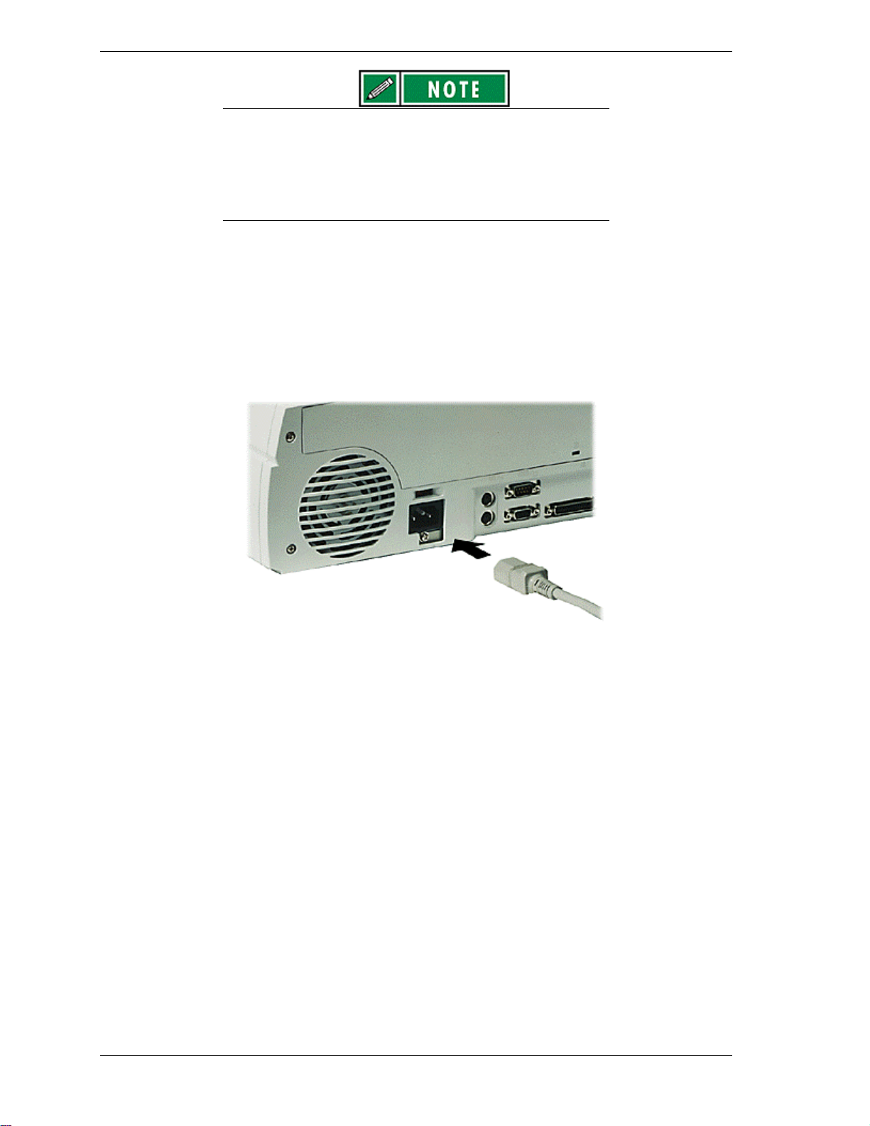
1. Position the NEC Versa Dock on a flat surface close to an AC outlet.
1. Attach one end of the cable to the AC power port on the NEC Versa Dock.
1. Attach the other end to a properly grounded wall outlet.
Connecting the power cable
The NEC Versa Dock is now powered on.
2-8 System Configuration and Setup
Page 25

Disconnecting the power cable or experiencing a power
outage while running the NEC Versa Dock and NEC Versa
can cause the system to suddenly power off, resulting in a
possible loss of data.
Preparing the NEC Versa for Docking
Follow the procedure given below to prepare the NEC Versa for docking.
1. Set the NEC Versa power for your system as follows.
n If you have an NEC Versa with a Plug and Play operating system such
as Windows 95, you can either put your system into Suspend mode,
leave it in full Operation mode for docking, or you can choose to power
off.
n If you have a non-Plug and Play operating system such as Windows NT
4.0, turn off the system power before docking.
Make sure your system is in the appropriate mode for
docking.
2. If you are running the NEC Versa on AC power, save any open files, close
open applications and disconnect the AC adapter cable from the NEC Versa.
Before disconnecting power, save any open files or close
open applications to avoid data loss.
3. On the back of the NEC Versa, open the expansion port cover and slide it
underneath the expansion port. Check that all other NEC Versa port covers
are closed.
Opening the NEC Versa expansion port cover
System Configuration and Setup 2-9
Page 26
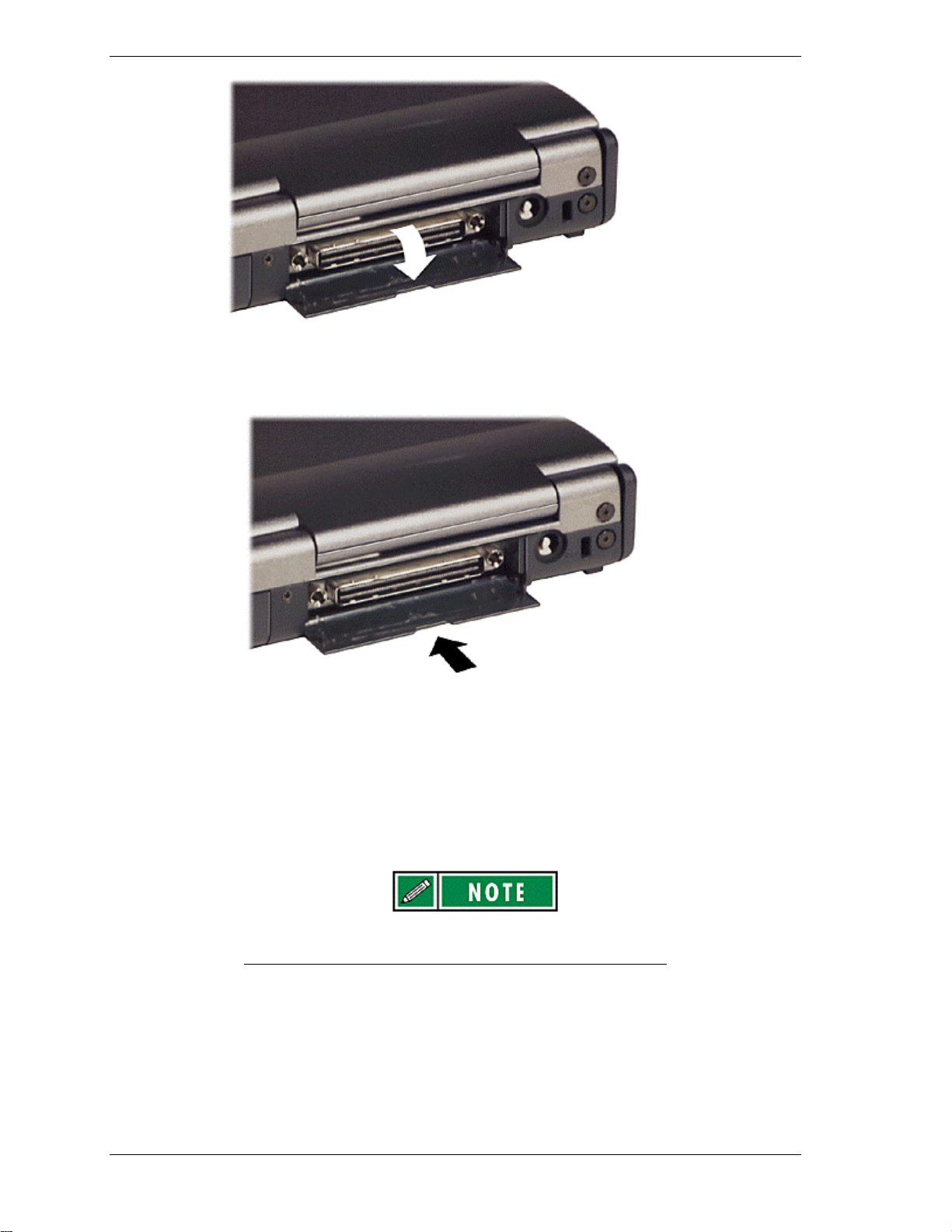
Stowing the expansion port cover
4. Verify that the power cord is plugged into the NEC Versa Dock. (See
“Connecting the Power Cable” for details.)
5. Ensure that the keylock switch is in the Normal position.
Motorized docking is only enabled when the keylock switch
is in the full upright position.
2-10 System Configuration and Setup
Page 27
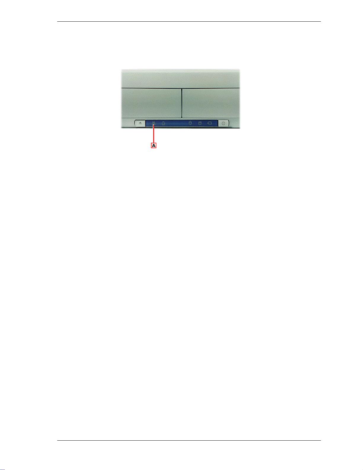
When the Docking Status LED light is steady yellow, the NEC Versa Dock is
ready for motorized docking.
A - Docking status LED
Docking the NEC Versa
Docking Status LED
You can dock the NEC Versa in one of the following modes:
n Cold Docking — with NEC Versa system power off. This method works
for all NEC Versa models that support docking.
n Warm Docking — with NEC Versa power on, the system in Suspend
mode, and NEC Versa Dock power on. This procedure can be used with
NEC Versa systems with Plug-and-Play operating systems, such as
Windows 95.
n Hot Docking — with NEC Versa power on and the system in full
operation mode. This procedure can be used with NEC Versa systems
with a Plug and Play operating system, such as Windows 95.
System Configuration and Setup 2-11
Page 28
Use the following steps to dock your NEC Versa.
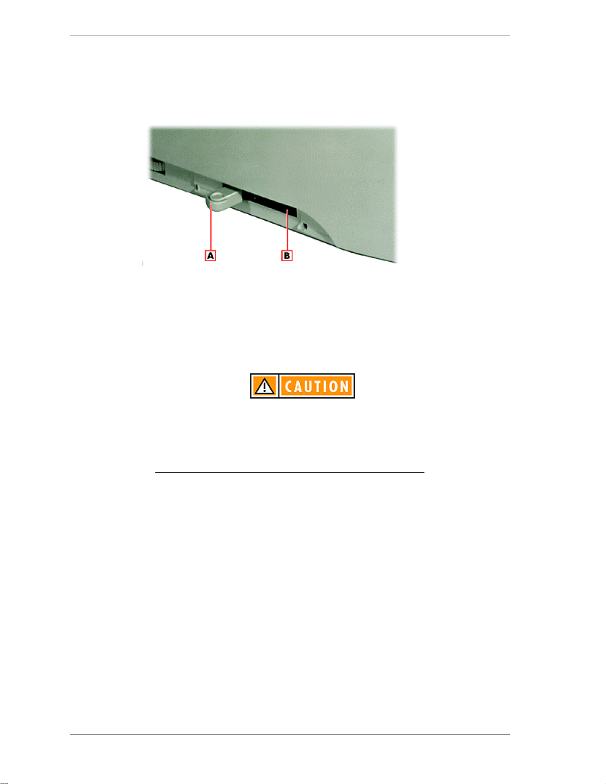
1. Locate the height lever on the left side of the unit.
Locating the height lever
A - Height lever position II B - Height lever position I
1. Set the height lever on the side of the NEC Versa Dock to match your
system as follows:
It is important that the height lever is set to the correct
height for system docking. The NEC Versa Dock will not
properly dock the NEC Versa if the height lever is set
incorrectly, which may result in system damage to either the
NEC Versa Dock or the NEC Versa. The Docking LED blinks
amber if the height lever is set incorrectly.
n If you have an NEC Versa LX, set the lever to I by sliding the lever to
the front.
n If you have an NEC Versa SX, set the lever to II by sliding the lever to
the rear.
3. Verify that the keylock switch is in the “Normal” position.
Keylock switch in the Normal position
2-12 System Configuration and Setup
Page 29
4. Close the LCD panel on the NEC Versa.
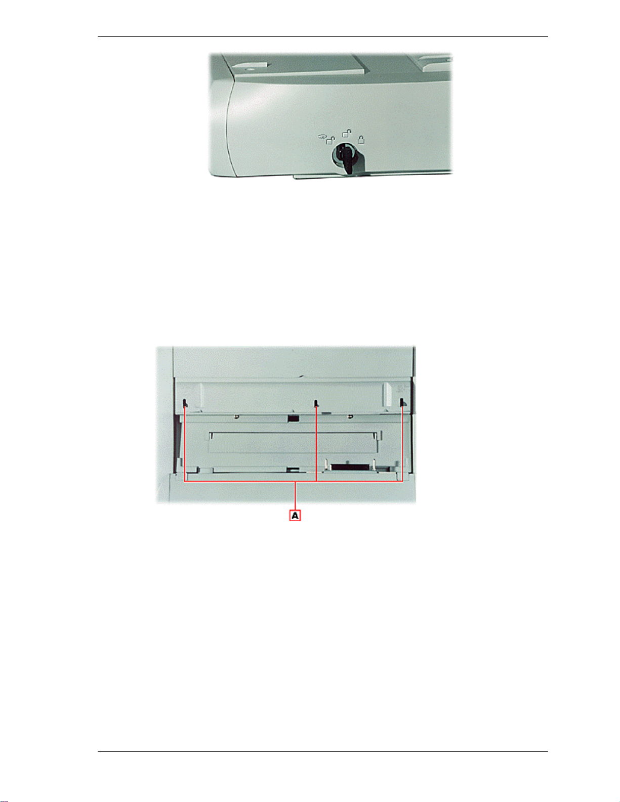
5. Slide the NEC Versa onto the NEC Versa Dock. Ensure that the three
locking teeth on the NEC Versa Dock fit into the three locking slots on the
bottom of the NEC Versa.
Locating the locking teeth
System Configuration and Setup 2-13
Page 30
A - NEC Versa Dock locking teeth
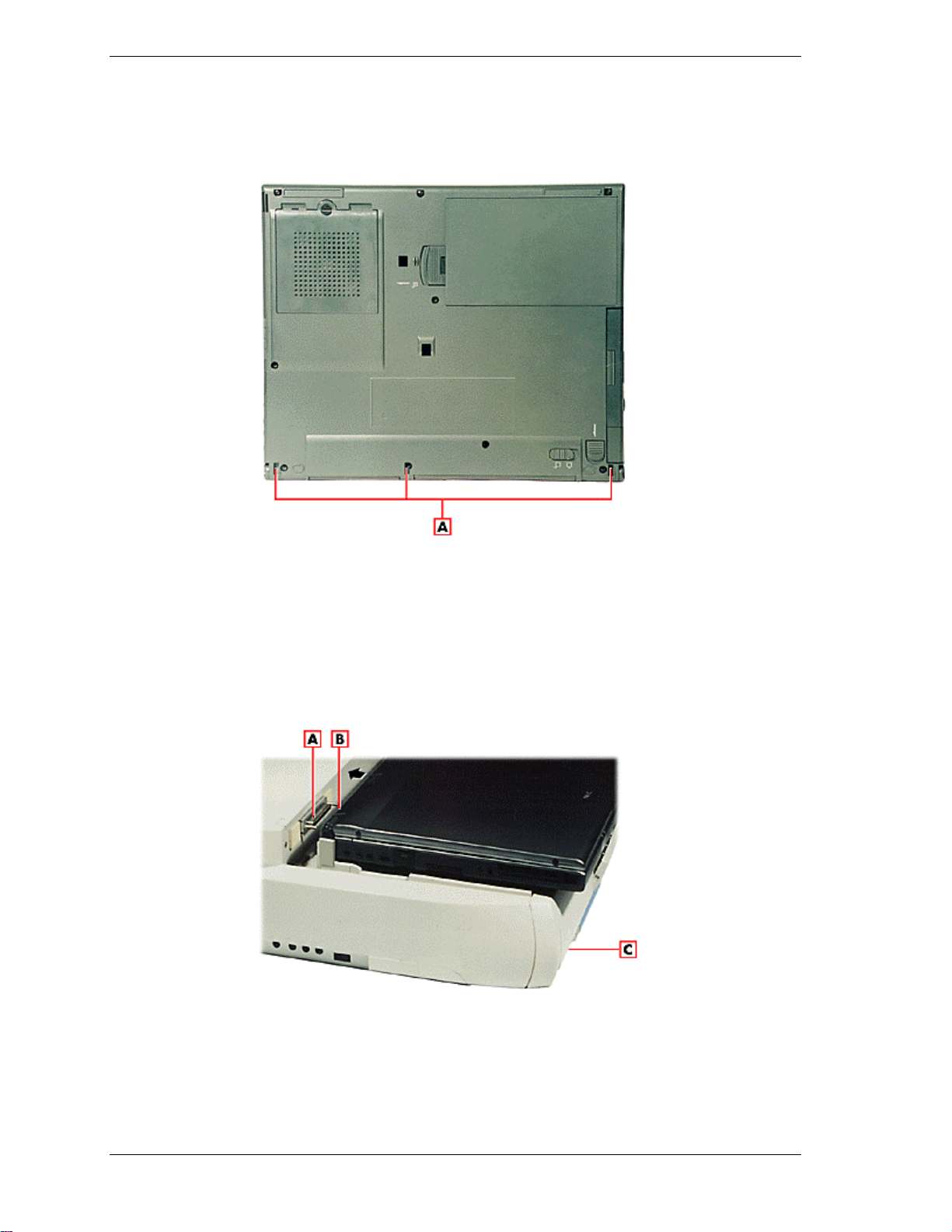
Locating the locking slots
A - NEC Versa locking slots
Once the notebook is properly seated on the docking teeth, the docking
connector and the expansion port are properly aligned.
Aligning the NEC Versa with the NEC Versa Dock
2-14 System Configuration and Setup
Page 31

A - Docking connector on the NEC Versa Dock
B - Docking connector on the NEC Versa (not shown)
C - Dock/Undock button
6. Verify that the Docking LED is a steady yellow.
7. Press the Dock/Undock button on the left of the front panel. The system
automatically docks.
If the system does not automatically dock, ensure that the height lever is in
the correct position for your system and that the system is correctly seated
on the docking tray.
Pressing the Dock/Undock Button
A - Dock/Undock button
8. If the Docking Status LED blinks amber, remove the NEC Versa using the
Dock/Undock button, reseat it, and retry docking.
8. If using the NEC Versa without an external monitor, open the LCD panel.
10. If the system was cold docked, press the Power button on the NEC Versa
Dock to power on the NEC Versa.
11. Verify that the Docking Status LED is steady green, indicating the NEC
Versa is properly docked on the NEC Versa Dock.
Once docked, you can lock the NEC Versa onto the NEC Versa Dock using the
key provided. See the following section “Locking the NEC Versa” for details.
Locking the NEC Versa
Turn the key on the side of the NEC Versa Dock to lock the NEC Versa onto the
NEC Versa Dock. You can choose one of the three following locking states.
System Configuration and Setup 2-15
Page 32

n Locked – This setting keeps the NEC Versa from being removed from the
NEC Versa Dock. You must use the key to unlock the unit before
removing the NEC Versa. An alarm sounds if someone tries to remove
the NEC Versa while it is locked onto the NEC Versa Dock, even if the
NEC Versa Dock is powered off or is not connected to AC power.
There is an intermediate position or stop between the
Normal and Manual positions. This is not a valid
position for proper operation of the NEC Versa Dock.
Attempting to move the NEC Versa system with the key
in this intermediate position could result in excessive
noise from the NEC Versa Dock motor. When using the
keylock, make sure to fully turn the key to the desired
Normal or Manual position.
It may be necessary to apply additional pressure when
turning the keylock to the Manual position.
Turning the keylock switch to Locked
n Normal – this default position allows you to motorize dock or undock the
NEC Versa. Set the keylock to this position for normal use. To prevent
electrical damage, manual undocking is not allowed when the keylock is
in this state.
Turning the keylock switch to Normal
2-16 System Configuration and Setup
Page 33

System Configuration and Setup 2-17
Page 34

n Manual – Allows you to remove the NEC Versa by hand. Use the
unlocked position for emergency undocking only. Otherwise, use the
Normal lock setting for normal use and the Locked setting to secure your
system to the NEC Versa Dock. The Manual setting requires manual
removal of the computer and resetting the keylock to Locked.
Turning the keylock switch to Manual
If no computer is docked and the keylock is in the Locked position, no
one else can use their computer on the NEC Versa Dock.
The Keylock Status LED lights as follows to indicate the status of the NEC
Versa Dock.
n Off – The NEC Versa is not docked.
n Steady Amber – The NEC Versa is docked but not locked on the NEC
Versa Dock. The key is in either the Normal position with the NEC Versa
turned off, or in the Manual position with the NEC Versa on or off.
n Steady Yellow – The NEC Versa is locked onto the NEC Versa Dock
through software. The key is in the Normal position and the NEC Versa
is on.
n Steady Green – The NEC Versa is physically locked onto the NEC Versa
Dock. The key is in the Lock position with NEC Versa power on or off.
Undocking the NEC Versa
Undock your NEC Versa as follows.
1. Check the status of your NEC Versa power:
If you are running a non-Plug and Play operating system such as Windows
NT 4.0, save your files, close any open applications and exit Windows.
2. For easier undocking, close the LCD panel. (This is not required, but is
recommended.)
Ensure that all cables connected to the sides of the NEC
Versa are disconnected prior to undocking the system. Also
2-18 System Configuration and Setup
Page 35

ensure that CD/DVD drives are closed and that no diskettes
or SuperDisks are extending from the drive.
3. Verify that the keylock switch is in the Normal position.
Keylock Switch in the Normal Position
4. Press the Dock/Undock button on the front of the NEC Versa Dock. As the
docking tray slides forward, the NEC Versa mechanically ejects from the
NEC Versa Dock.
A - Dock/Undock button
To use Windows 95 software to undock the NEC Versa, locate and select the
“Eject PC” icon in the Windows 95 Start menu. When you select this icon, a
“Dock Change” window appears.
5. The NEC Versa Dock automatically ejects the NEC Versa.
Emergency Undocking
Docking/Undock Button
To undock your NEC Versa Dock in the event of a power failure or other
emergency, undock the unit as follows.
1. Turn the keylock switch to the Manual position.
Keylock switch in the Manual position
System Configuration and Setup 2-19
Page 36

Ensure that all cables connected to the sides of the NEC
Versa are disconnected prior to undocking the system. Also
ensure that CD/DVD drives are closed and that no diskettes
or SuperDisks are extending from the drive.
Note: There is an intermediate position or stop between
the Normal and Manual positions. This is not a valid position
for proper operation of the NEC Versa Dock. Attempting to
move the NEC Versa system with the key in this
intermediate position could result in excessive noise from
the NEC Versa Dock motor. When using the keylock, make
sure to fully turn the key to the desired Normal or Manual
position.
It may be necessary to apply additional pressure when
turning the keylock to the Manual position.
2-20 System Configuration and Setup
Page 37

2. Remove the CRT table from the NEC Versa Dock.
3. Release the NEC Versa from the NEC Versa Dock by firmly pulling the
front of the NEC Versa with equal pressure to the right front and the left
front.
4. Continue to pull until the NEC Versa is free from the NEC Versa Dock.
Releasing the NEC Versa from the NEC Versa Dock
Installing Options and Connecting Devices
You can optimize your NEC Versa’s functionality by installing options in the
NEC Versa Dock. Options can be installed in the following bays and slots:
n File Bays — two file bays on the front of the NEC Versa Dock give you
external access to installed devices.
In the left front file bay, you can install any optional 5.25-inch IDE
device, and with a 3.5-inch Universal Installation Kit, you can install
any 3.5-inch IDE device.
In the right front file bay you can install any optional IDE device or
the optional VersaBay III Adapter Kit. With this Adapter Kit, you can
change this file bay into a VersaBay III slot that lets you use your
VersaBay III devices in the NEC Versa Dock.
n Two PCI Board Slots — Two slots let you add two PCI cards to your
NEC Versa Dock. One slot supports a full-size card and both slots
support a half-size PCI card.
n I/O ports on the sides and back of the NEC Versa Dock let you connect
the following external devices:
Parallel device
External monitor
Serial device
PS/2 keyboard and PS/2 mouse (separate ports for each)
System Configuration and Setup 2-21
Page 38

USB devices (two ports with hub)
MIDI/Game devices
Audio devices.
Installing Devices in the File Bays
The NEC Versa Dock has two 5.25-inch half-height bays for installing optional
devices. The bay located on the right front of the NEC Versa Dock (the side
closest to the keylock), supports the installation of an optional VersaBay III
Adapter Kit. Installing the Adapter Kit transforms the bay into a VersaBay III.
You can then use your optional VersaBay III devices in the NEC Versa Dock.
Installing devices in the file bays involves the following procedures:
n Removing the NEC Versa Dock docking tray, front panel and cable
cover.
n Disconnecting the cables from the motherboard.
n Connecting the cables to the device.
n Installing the device in the NEC Versa Dock.
n Reconnecting the cables to the motherboard.
n Replacing the NEC Versa Dock cable cover, docking tray and front
panel.
Use the instructions in the sections that follow to install an IDE device in a file
bay and to install the optional VersaBay III Adapter Kit.
Installing Devices in the File Bays
The NEC Versa Dock has two 5.25-inch half-height bays for installing optional
devices. The bay located on the right front of the NEC Versa Dock (the side
closest to the keylock), supports the installation of an optional VersaBay III
Adapter Kit. Installing the Adapter Kit transforms the bay into a VersaBay III.
You can then use your optional VersaBay III devices in the NEC Versa Dock.
Installing devices in the file bays involves the following procedures:
n Removing the NEC Versa Dock docking tray, front panel, and cable
cover.
n Disconnecting the cables from the motherboard.
n Connecting the cables to the device.
n Installing the device in the NEC Versa Dock.
n Reconnecting the cables to the motherboard.
n Replacing the NEC Versa Dock cable cover, front panel, and docking
tray.
2-22 System Configuration and Setup
Page 39

Removing Trays, Panels, and Covers
Before installing a device in one of the NEC Versa Dock file bays, you must
remove the docking tray, front panel, and cable cover. Do so as follows:
1. Unplug the NEC Versa Dock, disconnect any peripheral devices that are
attached, and undock the NEC Versa if it is docked.
1. Disconnect any external cables that might be attached on an installed PCI
board (such as a network board).
3. Turn the keylock switch to the Manual position to disengage the motor
mechanism.
Keylock switch in the Manual position
4. Remove the front part of the docking tray. First locate and remove the
rubber pads securing the three screws, then loosen and remove the three
screws. Lift the docking tray up and off the NEC Versa Dock.
Removing the docking tray
System Configuration and Setup 2-23
Page 40

5. Remove the front panel from the NEC Versa Dock by removing the two
screws at the bottom and freeing the four tabs from the top of the panel. Put
the screws in a safe place for use when replacing the front panel.
Removing the front panel
A - Front panel tabs (4) B - Front panel screws (2)
6. Slide the rear part of the docking tray towards the front of the NEC Versa
Dock until it stops.
7. Remove the cable cover by locating and removing the two top screws. Put
the screws in a safe place for use when replacing the cable cover.
Locating the cable cover screws
A - Cable cover screws (2)
2-24 System Configuration and Setup
Page 41

8. Lift the cable cover up and off the NEC Versa Dock.
Removing the cable cover
You are now ready to disconnect the cables from the motherboard. (See the
instructions in “Disconnecting the Cables from the Motherboard” for details.)
Disconnecting the Cables from the Motherboard
Disconnect the cables from the motherboard as follows.
1. Before handling any internal components, discharge static electricity from
yourself and your clothing by touching a nearby metal surface.
2. See the appropriate figure for the bay that you are using to disconnect cables
from the motherboard.
The following figure shows cable locations in the NEC Versa Dock.
Left-hand bay cables and ports
System Configuration and Setup 2-25
Page 42

A - Power cable port B - IDE signal port C - Audio cable port
D - Audio cable E - IDE signal cable F - Power cable
Right-hand bay cables
A - VersaBay III cable port B - Power cable port C - IDE signal port
D - Audio port E - IDE signal cable F - Power cable G - VersaBay III cable
3. If you are installing a device in the right-hand file bay and you need an
audio cable, remove the audio cable from behind the left-hand bay. The
NEC Versa Dock comes with only one audio cable.
You are now ready to attach the cables to the appropriate ports on the back of
the device. (See the instructions in “Connecting IDE Device Cables” for details.
If you are installing an optional VersaBay III device, see the instructions in
“Connecting VersaBay III Adapter Kit Cables” for details.)
Connecting IDE Device Cables
Connect the cables to the IDE device as follows.
1. Before handling any internal components, discharge static electricity from
yourself and your clothing by touching a nearby metal surface.
2-26 System Configuration and Setup
Page 43

2. Locate the power cable and IDE signal cable port, and if necessary, the
audio cable port on the back of the IDE device.
System Configuration and Setup 2-27
Page 44

Locating and connecting the cables to the IDE device
A - Audio cable port B - IDE signal cable port C - Power cable port
D - Power cable E - IDE signal cable F- Audio cable
3. Connect the appropriate power cable, the IDE signal cable, and if necessary
the audio cable to the ports on the back of the IDE device. The IDE cable
must be installed with the red stripe to the left side of the device.
4. Ensure that the IDE connector pin is oriented correctly on the IDE signal
cable.
If the power cable for the device you are installing uses a
small connector, use one of the cables provided in the
accessory kit.
You are now ready to install the IDE device into the file bay. (See the
instructions in “File Bay Installation” for details.)
2-28 System Configuration and Setup
Page 45

Connecting VersaBay III Adapter Kit Cables
Connect the VersaBay III Adapter Kit cables as follows.
1. Locate the IDE cable port, the VersaBay III signal cable port, and the
VersaBay III power cable port.
Locating and connecting the cables to the VersaBay III device
A - IDE signal cable port B - Power cable port C - VersaBay III cable port
D - VersaBay III cable E - Power cable F - IDE signal cable
2. Connect the cables to the appropriate ports on the back of the optional
VersaBay III Adapter Kit.
You are now ready to install the optional VersaBay III Adapter Kit into the file
bay. (See the instructions in “File Bay Installation” for details.)
File Bay Installation
Install an IDE device or the optional VersaBay III Adapter Kit in the file bay as
follows.
1. Before handling any internal components, discharge static electricity from
yourself and your clothing by touching a nearby metal surface.
2. Remove the NEC Versa Dock front panel, docking tray, and cable cover.
(See the instructions in “Removing Trays, Panels, and Covers” for details.)
3. Remove the cables from the motherboard. (See the instructions in
“Disconnecting Cables from the Motherboard” for details.)
System Configuration and Setup 2-29
Page 46

4. Attach the cables to the IDE device or the optional VersaBay III Adapter
Kit. (See the instructions in “Connecting IDE Device Cables” or
“Connecting VersaBay III Adapter Kit Cables” for details.)
5. Locate and remove the screw that secures the device bracket in the bay. (Put
the screw in a safe place for use during reassembly.)
Removing the screw securing the device bracket
A - Device bracket screws (2)
As an added security feature, the keylock switch must be in
the Manual position before the file bay brackets can be
removed. If the keylock switch is in the Locked position, the
file bay bracket will not slide forward. This prevents device
removal while the keylock switch is in the Locked position.
6. Verify that the keylock switch is in the Manual position. The device bracket
will not slide out of the file bay unless the keylock is in the Manual position.
7. Slide the device bracket out of the NEC Versa Dock.
Removing the bracket
2-30 System Configuration and Setup
Page 47

8. Fit the IDE device into the bracket and determine which of the two front-to-
back positions best suits the type of device you are installing.
Installing a 3.5-inch IDE device in the file bays without a
3.5-inch Universal Installation Kit can short circuit and burn
out the device. Be sure to install 3.5-inch IDE devices in the
file bays using a 3.5-inch Universal Installation Kit.
9. Align the screw holes on the side of the device with the screw holes on the
bracket. Attach the device to the bracket using the four screws that came
with the IDE device.
Attaching the device to the bracket
A - Device bracket screws (4)
10. Slide the device and bracket into the file bay.
Sliding the device and bracket into the file bay
System Configuration and Setup 2-31
Page 48

11. Secure the screw that attaches the bracket to the NEC Versa Dock.
Securing the bracket and device screw
A - File bay bracket screw
12. If you have another file bay device to install, do so before replacing the
cable cover, docking tray, and front panel.
You are now ready to reconnect the cables to the motherboard.
Reconnecting the Cables to the Motherboard
Reconnect the cables to the motherboard as follows.
1. Before handling any internal components, discharge static electricity from
yourself and your clothing by touching a nearby metal surface.
2. Locate the power cable slot, IDE signal cable slot, and the audio cable slot
(if necessary) found directly behind the IDE device installed. If you are
installing the optional VersaBay III Adapter Kit, also locate the VersaBay III
cable slot.
Locating ports and reconnecting cables to the left side of the motherboard
2-32 System Configuration and Setup
Page 49

A - Power cable port B - IDE signal cable port C - Audio cable port
D - Audio cable E - IDE signal cable F - Power cable
Locating ports and reconnecting cables to the right side of the motherboard
A - VersaBay III cable port B - Power cable port C - IDE signal cable
D - Audio Port E - IDE signal cable F - Power cable G - VersaBay III cable
3. Reconnect the appropriate power cable and the IDE cable to the
motherboard. Also connect the audio cable or VersaBay III cable, if
necessary, to the motherboard.
You are now ready to replace the NEC Versa Dock cable cover. (See the
instructions in “Replacing Covers, Panels, and Trays” for details.)
Replacing Covers, Panels, and Trays
Replace the NEC Versa Dock cable cover, front panel, and docking tray as
follows.
1. Align the tabs on the cable cover with the slots.
2. Lower the cable cover onto the NEC Versa Dock.
Lowering the cable cover onto the NEC Versa Dock
System Configuration and Setup 2-33
Page 50

3. Replace the two screws on the top of the cable cover.
Replacing the cable cover screws
A - Cable cover screws (2)
4. Slide the rear part of the docking tray towards the back of the NEC Versa
Dock until it is seated properly.
2-34 System Configuration and Setup
Page 51

Make sure the docking connector is aligned with the hole in
the docking tray as you slide the docking tray into place.
System Configuration and Setup 2-35
Page 52

5. You are now ready to replace the front panel. If the device(s) you installed
require(s) external access, remove the appropriate file bay cover(s) on the
front panel by squeezing the two inside tabs together and gently pushing the
bay cover out of the front panel.
NEC Versa Dock file bay covers
A - Bay cover tabs (2)
6. Replace the front panel on the NEC Versa Dock by aligning the four tabs at
the top then replacing the two bottom screws.
Replacing the front panel
A - Front panel tabs (4) B - Front panel screws (2)
2-36 System Configuration and Setup
Page 53

7. Replace the front part of the docking tray. Lower the front part of the
docking tray onto the NEC Versa Dock, secure the three screws, then finish
with the three rubber feet.
Replacing the docking tray
Installing PCI Cards
Two PCI slots let you add two PCI cards to your NEC Versa Dock. The top slot
supports a full-size PCI card and both slots support a half-size (or smaller) PCI
card. PCI connectors are located in the back of the NEC Versa Dock. Only the
top slot supports a full-size card.
The optional NEC 3Com Fast EtherLink LX provides a networking solution for
the NEC Versa Dock for systems running Windows 95 and Windows NT 4.0.
This PCI card supports Wake on LAN technology, which allows you to manage
your networked systems remotely.
For installation and configuration information, see the documentation that came
with the NEC 3Com Fast EtherLink LX.
Follow these steps to install a PCI card in the NEC Versa Dock.
1. Unplug the NEC Versa Dock before installing or removing any PCI cards.
2. Remove the back cover by locating and removing the two screws.
3. Put the screws in a safe place for use when replacing the cover.
System Configuration and Setup 2-37
Page 54

Locating and Removing the Back Cover Screws
A - Back cover screws (2)
4. Locate and remove the slot cover screw. If you are installing a full-size card,
remove the top PCI slot cover screw and the slot cover.
Removing the slot cover screw
A - Wake-On LAN connector B - Slot cover screws
5. Align the PCI card with the slot connector.
Inserting the card
2-38 System Configuration and Setup
Page 55

6. Firmly push against the card until the connection is secure. If internal SCSI
devices are being installed, the device cable(s) must be routed from the PCI
card to the file bays. Feed one end of the cable through the left side of the
back of the unit and gently pull it toward to the back of the SCSI device.
Connect to the SCSI device and the card.
7. Replace the slot cover screw to secure the card.
Securing the card
7. Attach device cables to the installed PCI card.
8. Replace the back cover of the NEC Versa Dock and secure it with the two
screws.
9. Reconnect the power cable.
Using PCI Cards
When using PCI cards, it is important that you check that the device is not
enabled in all configurations in the Device Manager. You can check this by
using the following procedure.
1. After installing the PCI card and drivers, click Start, Settings, and Control
Panel.
2. Double click System.
3. Click the Device Manager tab. Select the card type from the list, highlight
the PCI card, and click Properties.
4. Under the General tab, make sure the box “Exists in all hardware profiles” is
not checked. If it is checked, remove the check.
A- Slot cover screw
System Configuration and Setup 2-39
Page 56

For more information on using multiple configurations in Windows 95, search
for “hardware profiles” in Windows Help.
Installing PC (PCMCIA) Cards
If you plan to use a PC card while your NEC Versa is in the NEC Versa Dock, it
is recommended that you dock the system before installing the card. The IDE
controller inside the NEC Versa Dock uses IRQ11 and if the card is installed
before docking it could cause a resource conflict with the system.
Connecting External Devices
Review the following sections for instructions on connecting external devices to
the NEC Versa Dock.
Serial Device
The NEC Versa Dock is equipped with an industry standard 9-pin RS-232C
serial port. Use this port to install a serial device such as a printer or an external
modem.
When you connect a printer, be sure to install the
appropriate printer driver through the Windows Control
Panel.
Follow these steps to connect a serial device to your NEC Versa Dock.
1. Check that both the NEC Versa and the device power are off.
2. Align and connect the 9-pin connector to the serial port on the NEC Versa
Dock.
3. Secure the connection with the screws provided on the cable.
4. Align and connect the other end of the cable to the appropriate port on the
device, if necessary. Secure the connections with the screws provided, if
necessary.
2-40 System Configuration and Setup
Page 57

Connecting a serial device
5. Connect the power cable to the device and a properly grounded wall outlet.
6. Turn on the power to the external device.
Make sure your printer is online before trying to print. See
the printer’s user’s guide for instructions.
7. Turn on the power to the NEC Versa Dock.
External Keyboard and Mouse
You can connect a full-size PS/2-style keyboard and/or PS/2-style mouse to
your NEC Versa Dock. You can continue to use the system keyboard or
VersaGlide while an external keyboard or mouse is connected.
Follow these steps to connect an external keyboard or mouse to your system.
1. For non-Plug and Play operating systems such as Windows NT 4.0, power
off the NEC Versa.
System Configuration and Setup 2-41
Page 58

For non-Plug and Play operating systems such as Windows
NT 4.0, make sure the NEC Versa is powered off whenever
you add or remove an external keyboard or mouse.
Connecting an external keyboard or mouse to the system in
Operation mode can cause the system or device to
malfunction.
2. Connect the keyboard cable connector to the keyboard port on the NEC
Versa Dock. Connect the mouse cable connector to the mouse port on the
NEC Versa Dock.
Connecting an external keyboard and mouse
3. For non-Plug and Play operating systems such as Windows NT 4.0, power
on the system. The system immediately recognizes the keyboard or mouse.
External Monitor
The NEC Versa Dock is equipped with an industry standard 15-pin VGA
monitor connector. The monitor connector supports a video graphics array of
various resolutions. See the monitor’s user’s guide for details.
Follow these steps to connect an external monitor to the NEC Versa Dock.
After you connect an external keyboard, you can use both
the built-in keyboard and external keyboard simultaneously.
(Only the numeric keypad on the external keyboard works in
this case.)
2-42 System Configuration and Setup
Page 59

1. Check that the docked NEC Versa is powered off and the monitor power
switch is turned off.
The docked NEC Versa must be powered off while the
monitor is being connected or the system does not
recognize the monitor type.
2. Position the monitor as follows:
n To use the monitor without the monitor stand, simply place the monitor
on a flat surface next to the NEC Versa Dock.
n To use the monitor stand
Close the LCD panel on the NEC Versa.
Lower the monitor stand onto the NEC Versa Dock.
Carefully center the external monitor on the monitor base.
Lowering the monitor base into place
System Configuration and Setup 2-43
Page 60

3. Attach the 15-pin cable connector to the monitor port on the NEC Versa
Dock.
4. Secure the cable connection with the screws provided on the cable.
Connecting a monitor cable
5. Connect the monitor power cable and plug it into a properly grounded wall
outlet.
6. Follow any setup instructions in the monitor’s user’s guide.
7. Power on the monitor.
8. Power on the NEC Versa.
Press Fn-F3 to toggle between the LCD, CRT, simultaneous CRT/LCD display,
and TV Out (on systems that support TV Out).
Parallel Devices
To install a parallel device such as a printer, you need a cable with a male 25pin connector for the system and, for most parallel printers, a Centronics®compatible 36-pin connector.
Connect a parallel device to the NEC Versa Dock as follows.
When you connect a printer, be sure to install the
appropriate printer driver through the Windows Control
Panel.
1. Check that both NEC Versa and the parallel device power are off.
2-44 System Configuration and Setup
Page 61

2. Align and connect the 25-pin parallel cable connector to the parallel port on
the NEC Versa Dock. Secure the cable with the screws provided.
3. Align and connect the other end of the cable to the parallel port on the
device. Lock the connector clips.
System Configuration and Setup 2-45
Page 62

Connecting a parallel printer
4. Connect the power cable to the device and a properly grounded wall outlet.
5. Turn on power to the system and the device.
USB Devices
The NEC Versa Dock lets you take advantage of the latest USB technology
available to Windows 95 users.
Plug USB devices into your Windows 95 system as follows.
1. Locate the USB ports on the back of the NEC Versa Dock.
Check that the device is online before you try to use it. See
the instructions that came with the device for more
information.
The USB hub on both the NEC Versa and the NEC Versa
Dock are active at the same time. You can connect USB
devices to all three ports to further increase system
connectivity.
Any external USB hubs you wish to connect to the NEC
Versa Dock must have an external power supply.
2. Plug in the USB connector.
2-46 System Configuration and Setup
Page 63

MIDI/Game Devices
The MIDI/Game port lets you attach a joystick or MIDI device to your NEC
Versa Dock. Connect a joystick or MIDI device as follows:
Connecting a USB device
1. Check that both the NEC Versa and the device power are off.
2. Locate the MIDI/Game port on the side of the NEC Versa Dock.
3. Plug in the joystick or MIDI device and power on the MIDI device and NEC
Versa Dock.
Connecting a MIDI/Game device
System Configuration and Setup 2-47
Page 64

External Audio Options
The NEC Versa Dock automatically supports sound from the
system speakers on the NEC Versa, and also comes
equipped with built-in audio ports that let you record and
play sound. A volume control knob lets you control the
volume of connected external speakers or headphones.
Connect audio devices, like a microphone, line-out and line-in devices,
headphones, or optional external speakers to the audio ports as follows.
1. Power off the NEC Versa Dock and the NEC Versa.
2. Locate the audio port that you want to use.
: If the audio device you intend to use uses AC power, the
line out port is recommended. If the audio device is
unpowered, the headphone jack is recommended.
3. Plug the jack into the port on the side of the NEC Versa Dock.
Audio ports
A - Microphone port B - Line-in port
C - Line-out/speaker port D - External speaker/headphone port
4. Power on the NEC Versa Dock and NEC Versa.
2-48 System Configuration and Setup
Page 65

Connecting External Speakers
When the NEC Versa is docked, the system defaults to the NEC Versa speakers.
If you want to use optional external speakers with your NEC Versa Dock, do so
as follows.
1. On Windows 95, click Start, Settings, then Control Panel.
2. Double click on the Systems icon and click the Device Manager tab.
3. Double click on the Sound, Video and Game Controllers Icon, then double
click the Maestro Wave/WaveTable Synthesis Devices icon.
4. Click on the Dock Settings tab.
Dock Settings Dialog Box
5. Select the Output Audio To Docking Station Speakers.
This resets the default speakers to the NEC Versa Dock optional external
speakers. When you undock the system, your NEC Versa speakers will be
functional. When you dock again, the external speakers will be functional.
The volume control knob on the system controls NEC Versa speaker volume.
The volume control knob on the NEC Versa Dock controls the volume of
external speakers connected to the NEC Versa Dock.
System Configuration and Setup 2-49
Page 66

If you are using external speakers or an external microphone
and experience sound distortion or feedback, lower the
volume. Having the microphone and speakers too close to
each other can also cause feedback. Moving the external
audio options away from each other may help.
2-50 System Configuration and Setup
Page 67

3
Disassembly and Reassembly
n Required Tools and Equipment
n Disassembly
n Reassembly
Page 68

Required Tools and Equipment
All NEC Versa Dock corrective maintenance procedures can be performed
using the following tools:
n Key for the Versa Dock
n Tweezers
n Small flat-head screwdriver
n Phillips screwdriver ( #1 ) with a 6-inch shaft
n Right-angled dentist style probe.
Disassembly
This section contains step-by-step disassembly procedures for the system.
Reassembly is the reverse of disassembly. Each procedure is supported by a
simplified disassembly illustration to facilitate removal. These illustrations show
various items with callouts. A sub-assembly or part that was removed in a prior
step may be shown in the illustration. The illustration and callouts are accurate
for the described disassembly step.
The Illustrated Parts Breakdown and parts lists for the system unit are shown in
Section 5.
For complete disassembly of the Versa Dock, follow the disassembly order
listed below. To reassemble, follow the table in reverse order.
NEC Versa Dock Disassembly Sequence
Level of
Disassembly
1 Trays, Panels, and Covers
2 Disconnecting the Cables from the
3 Back Cover, Left and Right Sides, and Top
4 PCI Card and Expansion Bay Assembly
5 Table Assembly
6 Base Assembly (Main Board, LED Indicator
Components Available at Level of
Disassembly
Motherboard
Cover
Board, and Power Supply)
When disassembling the system unit, follow these general rules.
n Do not disassemble the system into parts that are smaller than those
specified in the procedure.
3-2 Disassembly and Reassembly
Page 69

n Use care when removing screws, note where each screw is removed as
screws differ in size.
n Label all removed connectors. Note where the connector goes and in
what position it was installed.
Preparation for Disassembly
Turn off and disconnect all power, all options, and remove the notebook.
Removing Trays, Panels and Covers
To remove the docking tray, front panel and cable cover. Do so as follows:
1. Undock the NEC Versa if it is docked, unplug the NEC Versa Dock, and
disconnect any peripheral devices that are attached.
2. Disconnect any external cables that might be attached on an installed PCI
board (such as a network board).
3. Turn the keylock switch to the Manual position to disengage the motor
mechanism.
Keylock switch in the Manual position
Disassembly and Reassembly 3-3
Page 70

4. Remove the front part of the docking tray. First locate and remove the
rubber pads covering the three screws, then loosen and remove the three
screws. Lift the docking tray up and off the NEC Versa Dock.
Removing the docking tray
5. Remove the front panel from the NEC Versa Dock by removing the two
screws at the bottom freeing the four tabs from the top of the panel.
Removing the front panel
A - Front panel tabs (4) B - Front panel screws (2)
6. Slide the rear part of the docking tray towards the front of the NEC Versa
Dock until it stops.
3-4 Disassembly and Reassembly
Page 71

7. Remove the cable cover by locating and removing the two top screws. Put
the screws in a safe place for use when replacing the cable cover.
Locating the cable cover screws
A - Cable cover screws (2)
8. Lift the cable cover up and off the NEC Versa Dock.
Removing the cable cover
You are now ready to disconnect the cables from the motherboard.
Disassembly and Reassembly 3-5
Page 72

Disconnecting the Cables from the Motherboard
Disconnect the cables from the motherboard as follows.
1. Before handling any internal components, discharge static electricity from
yourself and your clothing by touching a nearby metal surface.
2. See the appropriate figure for the bay that you are using to disconnect cables
from the motherboard.
The following figure shows cable locations in the NEC Versa Dock.
Left-hand bay cables
A - Power cable port B - IDE signal port C - Audio cable port
D - Audio cable E - IDE signal cable F - Power cable
Right-hand bay cables
3-6 Disassembly and Reassembly
Page 73

A - VersaBay III cable port B - Power cable port C - IDE signal port
D - Audio port E - IDE signal cable F - Power cable G - VersaBay III cable
Removing Device Brackets
1. Locate and remove the screw that secures the device bracket in the bay. (Put
the screw in a safe place for use during reassembly.)
Removing the screw securing the device bracket
A - Device bracket screws (2)
As an added security feature, the keylock switch must be in the Manual position before the file bay
brackets can be removed. If the keylock switch is in the Locked position, the file bay bracket will not
slide forward. This prevents device removal while the keylock switch is in the Locked position.
2. Verify that the keylock switch is in the Manual position. The device bracket
will not slide out of the file bay unless the keylock is in the Manual position.
3. Slide the device bracket out of the NEC Versa Dock.
Disassembly and Reassembly 3-7
Page 74

Removing the bracket
3-8 Disassembly and Reassembly
Page 75

Back Cover, Left and Right Sides, and Top Cover
1. Remove the back cover by locating and removing the two screws (A).
Locating and Removing the Back Cover Screws
A - Back cover screws (2)
2. Remove the back plate by locating and removing the six screws.
n four screws (B)
n two screws (C)
Rear of Versa Dock
3. Remove four top cover screws (A) on the front of the top cover.
Disassembly and Reassembly 3-9
Page 76

Top cover screws
4. Place docking height lever in position #II, turn keylock to the locked
position and remove key.
Use care to when removing or replacing plastic parts as the
locking tabs can be broken if forced.
5. Press down at the top cover notches and separate the side covers from the
top cover, tilt outward and lift from the notches on the base of the Versa
Dock.
6. Slide the top cover forward, then tilt the top cover forward and past the
docking pins, when clear of the docking pins, lift and remove.
Docking Connector Board, PCI Housing, and Power Supply
Remove the docking connector board, PCI card and expansion bay assembly as
follows:
1. Remove two screws (A) on the left side.
Left side
3-10 Disassembly and Reassembly
Page 77

2. Remove two screws on the right side opposite the two just removed from the
left side.
Disassembly and Reassembly 3-11
Page 78

3. Remove two screws on the main board (A) that secure the docking connector
board sub-assembly and PCI slot sub-assembly.
Docking connector board screws
4. Remove four screws (A). The screws (B & C) do not need to be removed to
remove the docking connector sub-assembly and PCI slot sub-assembly.
Rear screws
5. Lift the sub-assembly from the main unit.
3-12 Disassembly and Reassembly
Page 79

This sub-assembly contains the expansion connector board and the docking
connector board.
Remove the docking connector board by removing two screws (A) and the PCI
connector board by removing four screws (B).
Screws for the PCI connector board and docking connector board
Power Supply
Remove the power supply by removing four screws (two (C) on the back of the
unit and two on the interior which secure the two right angled feet of the power
supply). It is necessary to disconnect any cables that still may be connected to
the main board from the power supply.
Power Supply screws
Disassembly and Reassembly 3-13
Page 80

Docking Tray Assembly and Motor Assembly
Remove the docking tray assembly and motor assembly by removing eight
screws (A) (four from the left and four from the right) as shown below. Remove
the motor assembly by removing two screws (B) as shown in the illustration.
Left side screws
Right side screws
3-14 Disassembly and Reassembly
Page 81

Main Board Assembly
Follow these instructions to remove the main board.
1. Remove the two device bays by removing eight screws and lifting the device
bays from the unit.
2. Remove nine screws from the exterior of the unit,
three screws (B) from the left side,
and six screws (B) from the rear.
Left side
Rear view
3. Continue the main board removal by completing the following:
n Remove six screws from the main board and
n two screws from the cover plate,
n release the battery from the cover plate
n remove the cover plate.
n Lift the main board from the unit.
4. Remove eight stand offs to remove the two side panels.
Disassembly and Reassembly 3-15
Page 82

5. Remove the remaining items attached to the bottom assembly by removing
the appropriate screws.
Reassembly
Reassembly is the reverse of the disassembly process. Use care to insure that all
cables and screws are returned to their proper positions.
3-16 Disassembly and Reassembly
Page 83

System Board Layout
n Main Board
n LED Board
n PCI Expansion Board
4
Page 84

Main Board
LED Board
4-2 System Board Layout
Page 85

PCI Expansion Board
System Board Layout 4-3
Page 86

Illustrated Parts Breakdown
n NEC Versa Dock Illustrated Parts Breakdown
n Parts List
5
Page 87

NEC Versa Dock Illustrated Parts Breakdown
5-2 Illustrated Parts Breakdown
Page 88

Illustrated Parts Breakdown 5-3
Page 89

Parts List
The following table contains a listing of the field-replaceable parts and
corresponding part numbers.
Item
Number
1 IDE Cable Assy 808-740829-002-A
2 CD Signal Cable Assy 808-743294-001-A
3 5" File Power Cable Assy 808-743293-001-A
4 Buzzer 808-743526-001-A
5 BH072600-63 804-021205-002-A
6 PUZ001 808-892262-001-A
7 Front Cover Main Assy 136-243726-001-A
8 Sensor Pkg 136-533684-003-A
9 Side Cover (R) 136-640244-001-A
10 Key (only) 808-812976-***-A
11 Motor Assy 136-243410-001-A
12 Coin Lock Slim (C-289-1) (key &
cylinder)***
13 5" File Plate 136-638803-A
14 Front Mask Assy 136-243405-001-A
15 LED Badge 136-640256-A
16 Dummy Mask 136-640236-001-A
17 Dummy Mask 136-640236-001-A
18 5" File Plate 136-638803-A
19 5" File Plate (R) Assy 136-243725-001-A
20 5" File Plate (L) Assy 136-243412-001-A
21 Tilt Up Cap 136-640250-001-A
22 Side Cover (L) 136-640243-001-A
23 Ground Plate Included with item 43
24 Rear Panel 136-640234-001-A
25 PCI Slot Cover Assy 136-243667-001-A
26 PCI Slot Assy (Included with item
30)
27 Expansion Slot Cover Not a FRU item
28 PC I/F Pkg Unit Assy 136-243717-001-A
29 KENSINGTON BRACKET 136-639656-A
30 Connector Board Included with item 26
31 Bracket TBD
32 SW/LED FFC Assy 808-742860-005-A
33 DS Micro SW Cable Assy 808-743295-002-A
34 ASSHI RF 136-642032-A
35 ASSHI LR 136-642033-A
36 ASSHI LF 136-641712-A
37 ASSHI RR 136-642031-A
38 Bracket TBD
DESCRIPTION NEC PART NUMBER
808-812940-001-A
136-243413-001-A
5-4 Illustrated Parts Breakdown
Page 90

39 Top Cover Assy 136-243415-001-A
40 File Cover 136-640247-001-A
41 Table Plate Assy 136-243411-001-A
42 Side Cover (L) 136-640243-001-A
43 G7 Pkg Unit Assy (Main) 136-243407-001-A
44 Tray Plate Ground Included with item 43
45 Main Frame Assy 136-243408-001-A
NS File Cover Knob Included with item 14
NS Front Rubber Included with item 14
NS FG Strap (FGM-100-M3) 136-643513-A
NS Core (TFC-25-15-12) 808-090339-001-A
NS 5" File Plate Insulator 136-643289-A
NS Micro SW Cable Insulator 136-642691-A
NS CRT Table 136-243406-001A
NS Sensor Pkg Insulator 136-641060-A
NS Base Plate Assy 136-243722-001-A
NS Table Bush 136-642034-001-A
NS Sensor Cable Assy 808-743543-001-A
NS = Not shown
*** = key numbers (stamped on cylinders & keys), 101, 202, 303, 404, 505, 606, 707,
808, 909, 110, 211, 312, 413, 514, 615. 716. 817. 918. 220, 321, 422, 523, 624, 725
Illustrated Parts Breakdown 5-5
Page 91

Preventive Maintenance
n Precautions
n Battery Charging
n Routine Care
n Cleaning the Versa Dock Interior
n Protecting the Disk Drives
6
Page 92

Precautions
Follow these precautions when using and storing the NEC Versa Dock.
n Do not use or store the NEC Versa Dock in direct sunlight or near radiant
heat sources. Heat from these sources can raise the internal temperature
of the unit and damage its parts.
n Always use the power cable that comes with the NEC Versa Dock.
n Do not use or store the NEC Versa Dock in dusty environments.
n Do not use or store the NEC Versa Dock near chemicals.
n Do not cover the air vents or put anything near enough to them to block
air circulation.
n Avoid excessive vibration or shock. Dropping the NEC Versa Dock or
knocking it over can cause serious damage.
n Keep the NEC Versa Dock away from machinery that generates strong
electric or magnetic fields.
n Do not place heavy objects on the NEC Versa Dock. Make sure the CRT
base is in position before placing an external monitor on it. The CRT base
is designed to support an external monitor weighing no more than 55
pounds (25 kg). Do not place other heavy objects on the CRT base.
Battery Charging
The NEC Versa Dock charges the battery installed in the NEC Versa notebook
computer as long as the computer is docked and the NEC Versa Dock is plugged
into AC power.
The NEC Versa Dock charges a battery installed in the optional NEC VersaBay
III Adapter Kit as long as the NEC Versa Dock is plugged into AC power.
Battery charging occurs whether or not your NEC Versa notebook computer is
powered on.
6-2 Preventive Maintenance
Page 93

Routine Care
Maintain the condition of your NEC Versa Dock by periodically following the general procedures listed
below.
For safety, power off and unplug the NEC Versa Dock and NEC Versa before cleaning.
• Clean the outside of the NEC Versa Dock with a soft clean cloth.
• Remove stubborn stains with a cloth slightly dampened with a mild detergent. Never use a strong
solution or spray cleaner on any part of the unit.
• Check the NEC Versa Dock regularly for loose material, such as paper, books, or magazines, which
might block the air vents and prevent proper air circulation.
• Keep food and liquids away from the NEC Versa Dock and NEC Versa.
Preventive maintenance is limited to cleaning the plastic case, the keyboard, the display screen, and
the diskette drive heads, as required.
Cleaning the Versa Dock Interior
When servicing the inside of the notebook, remove dust and other foreign
particles from inside the system unit as follows:
1. Dust or vacuum (with a rubber-tipped nozzle) the inside of the system,
particularly the motherboard surface. Use care to avoid damaging or
dislodging any components or cables.
2. Inspect all cable connectors for damage. Ensure that connectors are seated
properly before replacing the cover.
Preventive Maintenance 6-3
Page 94

Protecting the Disk Drives
To protect the disk drives and data, back up the system disk periodically on
diskettes or the optional SuperDisk drive. Periodically use a head-cleaning
diskette in the disk drive to prolong the life of the drive and to help maintain
data integrity.
Here are some maintenance procedures to use when servicing a hard disk:
n Always back up the data files from the hard disk.
n Run a virus detecting program to check for possible virus infected areas
on the hard disk.
n Use the preinstalled ScanDisk program to correct any errors found in the
directory and File Allocation Table (FAT). This also frees up space from
any unused sectors.
n Never turn the computer off when the hard disk is being accessed.
n Never move or raise the computer while the hard disk is being accessed.
Be especially careful not to jar the hard disk during access, this can cause
a hard disk crash.
n Use hard disk maintenance program like DEFRAG under DOS, or
acquire Norton Utilities SPEEDISK programs. These programs
reorganize your hard disk by eliminating fragmentation and improve the
hard disk access time.
6-4 Preventive Maintenance
Page 95

Troubleshooting
n Quick Troubleshooting
n Helpful Questions
7
Page 96

Quick Troubleshooting
This section summarizes problems that may develop during Versa Dock and
notebook operation and lists suggested corrective actions.
Quick Troubleshooting
Problem Corrective Actions
No power Check that the AC power cable is plugged into the
power connector of the Versa Dock. Also, check that
the AC power cable is plugged into a properly
grounded AC power outlet.
Check the I/O board of the system. Is it inserted into
the CPU board connector properly? Otherwise, replace
the I/O board.
Data on the LCD is unreadable Check LCD Panel View Expansion in BIOS, Press Fn-
F10 to toggle Panel View Expansion for DOS mode.
Check if installed VGA driver is correct.
Check the VGA controller chip on the I/O board for any
loose soldering.
Replace the CPU board.
System halts during boot
sequence
I/O processing malfunctions Check the connections of all internal devices.
Diskette or LS-120 drive does
not work
Hard disk drive malfunction Check if hard disk drive is set properly on CMOS
Memory malfunction Check if the memory module is inserted properly.
Check condition of selected boot device (diskette, hard
disk or CD-ROM) for bad boot track or incorrect OS
files.
Try booting from a new bootable diskette and recopy
or repartition hard disk.
Check for any BIOS error messages on the display
screen.
Replace the CPU board or I/O board.
Check diskette type if correct and not faulty.
Replace the diskette drive.
Replace the I/O board.
SETUP.
Check drive connections.
Check if disk drive is good.
Replace the CPU board or I/O board.
7-2 Troubleshooting
Replace the memory module.
Replace the CPU board.
Page 97

External keyboard or PS/2
mouse doesn’t work
PC card does not work Check the PC card driver installation for any IRQ or I/O
NEC VersaGlide doesn’t work Check if PS/2 or Alps mouse driver is properly
Check if keyboard or mouse is connected properly.
Power off system first before plugging in the device.
Replace the keyboard or mouse.
Replace the CPU board or I/O board.
address conflict.
Check if the PC card is inserted properly and all
connections are set.
If the PC card is a Type II card, install it in the system’s
other PC card slot.
Replace the PC card.
Replace the I/O board.
installed.
Check VersaGlide cable inside the system if it is
inserted properly.
Clean VersaGlide surface.
Check the keyboard controller chip for any cold or
loose soldering.
Replace the CPU board.
Serial device does not work Check if device driver is installed properly.
Check if serial device is connected properly.
Check the device drive installation for any IRQ or I/O
address conflict.
Replace serial device.
Check the I/O controller chip on the main board for any
cold or loose soldering.
Replace the I/O board.
Parallel device does not work Check all connections.
Check if external device is turned on.
Check the device drive installation for any IRQ or I/O
address conflict.
Test another parallel device.
Check I/O controller chip on the main board for any
cold or loosed soldering.
Replace the I/O board.
Notebook will not dock/undock Check PnP operating system.
Adjust docking tray height to proper level.
Reset keylock.
Fan will not come on Get updated BIOS.
Troubleshooting 7-3
Page 98

Helpful Questions
Here are some helpful questions to ask when troubleshooting the Versa Dock
and a docked notebook computer:
n Is there any external power source connected to the Versa Dock?
n Is the computer turned on and the Power LED activated?
n Is the LCD display switched to an external monitor?
n Are all cables and devices connected properly and securely?
n Are all needed device drivers installed properly?
n Have you checked the AUTOEXEC.BAT and CONFIG.SYS files for
errors?
n Is the Standby Mode activated? Press any key or press the Power switch
to power on the system.
n Is the docking height lever in the correct position for the system being
docked?
7-4 Troubleshooting
Page 99

8
Getting Services and Support
n Services and Support Contact Information
n NEC NOW
n NEC CSD Web Site
n NEC CSD FTP Site
n NEC CSD FaxFlash Service
n Email/Fax to Support Services
n NEC CSD Bulletin Board
n NEC CSD Support Services
n NEC CSD Customer Assistance Center
n Versa Laptop Fulfillment Hotline
Page 100

Services and Support Contact Information
Service Contact Information
NEC NOW 888-8NEC-NOW (888-863-2669) or
888-306-4636
Web address: www.nec-now.com
NEC CSD Web and FTP Sites Web address: www.nec-computers.com
FTP site: ftp.neccsdeast.com
NEC CSD FaxFlashSM Service U.S. and Canada: 888-329-0088
International: 978-635-6090
Email to NEC CSD Support
Services through a commercial
online service or the Internet.
Fax Service to NEC CSD Support
Services
NEC CSD Bulletin Board System 978-635-4706
NEC CSD Support Services (U.S.
and Canada customers only).
NEC CSD Customer Assistance
Center
Versa Laptop Fulfillment Hotline 800-842-6446
Internet email address:
tech-support@neccsd.com
978-635-4100
800-632-4525
888-632-9128
Note: If you purchased your computer outside of the
U.S. or Canada, please contact the local NEC office or their
dealers for support and service.
See the booklet, “Getting Service and Support in Asia,
Australia, and Europe" to find out how to contact the local
office in your country.
If you have access to a telephone, modem, and/or fax machine, you can use
these services to obtain information about your system at any time, day or night,
seven days a week.
Not only do these services provide information about your NEC system, they
can also be used to answer your questions and help solve any problems you may
have with your system, should that ever be necessary.
8-2 Getting Services and Support
 Loading...