

Page 1
Ve r s a®E120 DayLite
Notebook Computer
™
User’s
Guide
Page 2

Proprietary Notice and Liability Disclaimer
The information disclosed in this document, including all designs and related materials, is the
valuable property of NEC Solutions (America), Inc. (hereinafter “NEC Solutions”) and/or its
licen sors. NEC Solution s and/or its li censor s, as appropr iate, r eserve all p atent, cop yright and oth er
proprietary rights to this document, in cluding all design, manufactur ing, repr oduction, use, and sales
righ ts thereto, ex cep t to the exten t said rights are expressl y granted to oth ers.
The NE C Sol u tions produ ct(s) discus sed in this document are warr an ted in accordance with the terms
of th e Warranty Sta tement a ccompan ying each product. However , actu al per formance of each such
product is depen dent upon factors such as system configuration, customer data, and operator control.
Since implementation by customers of each product may vary, the suitability of specific product
configurations and applications must be determined by the customer and is not warranted by NEC
Solutions.
To allow for design and specification improvements, the information in this document is subject to
change at any time, without notice. Reproduction of this documen t or portions thereof without prior
written approval of NEC Solutions is prohibited.
As an E
S
NEC is a registered trademark; Versa is a U.S. registered trademark; and DayLit e and VersaGlide are
trademark s of N E C Corpor ation an d/or one or m ore of its subsidia r ies. All are used un der license. E
S
of Mi crosoft C orporation. Intel and P entium are registered trademar ks and Spee dStep is a tr ademar k of In tel
Corporation.
All other product, brand, or trade names used in this publication are the trademarks or registered trademarks of
their respective trademark owners.
NERGY STAR
guidelines for energy efficiency.
TAR
is a U.S. registered trademark of the U.S. gove rnmen t. Micros of t and Wi ndows are registered trademar ks
TAR
partner, NEC Solutions has determined that this product meets the E
NERGY
NERGY
Fir st Printing — Mar ch 20 0 2
Copyright 2002
NEC Solutions (America), Inc.
15 Business Park Way
Sacramento, CA 95828
All Rights Reserved
Page 3

Contents
Using This Guide
Text Conventions............................................................................................................. x
Related Documents.......................................................................................................... x
1 Intr oducing the N EC Versa
Befor e You Begin.........................................................................................................1-2
About Your NEC Versa Notebook ................................................................................. 1-3
Around the Front of the System ..................................................................................... 1-4
Base Unit............................................................................................................... 1-4
System Con trols.....................................................................................................1-6
Power Button .................................................................................................. 1-6
Shortcut Buttons.............................................................................................. 1-7
Status LEDs........................................................................................................... 1-7
Power Status and E-mail LEDs........................................................................ 1-8
Drive and Keyboard Status LEDs.................................................................... 1-9
Keyboard Panel......................................................................................................1-9
Front Features...................................................................................................... 1-11
Around the Back of the System ................................................................................... 1-12
Around the Left Side of the System............................................................................. 1-13
Around the Right Side of the System...........................................................................1-14
Around the Bottom of the System................................................................................ 1-15
2 Getting Started
NEC VersaGlide Touchpad ........................................................................................... 2-2
VersaGlide Adjustments......................................................................................... 2-3
VersaGlide Tips.....................................................................................................2-3
Power Sources for Your NEC Versa.............................................................................. 2-3
AC Adapter .................................................................................................................. 2-4
Connecting the AC Adapter.................................................................................... 2-5
Powering On Your System.....................................................................................2-6
System Batteries ...........................................................................................................2-7
Primary Battery......................................................................................................2-7
Secon dary Batter y.................................................................................................. 2-7
Using th e Primar y Battery............................................................................................. 2-8
Determining Battery Status.....................................................................................2-8
Low Battery Status.................................................................................................2-9
Returning the Battery to its Normal State................................................................2-9
Extending Batter y Life........................................................................................... 2-9
Battery Han dling.................................................................................................. 2-10
Replacing th e Primary Battery.............................................................................. 2-10
Charging th e Battery............................................................................................ 2-13
Content s iii
Page 4

Battery Precautions.............................................................................................. 2-13
Precautions for Recharging the Battery................................................................. 2-14
Using a Secondary Battery.......................................................................................... 2-14
System Car e ............................................................................................................... 2-15
Precautions for System Use.................................................................................. 2-15
Storage Requirements.......................................................................................... 2-16
Routine Cleaning................................................................................................. 2-16
3 Using the BIOS Setup Utility
Introducing BIOS Setup................................................................................................ 3-2
Entering BIOS Setup .................................................................................................... 3-2
BIOS Setup Main Menu......................................................................................... 3-3
Loo k ing at Sc re ens................................................................................................. 3-4
Using Keys............................................................................................................ 3-5
Checking/Setting System Parameters ............................................................................ 3-5
Resetting System Parameters.................................................................................. 3-6
Main Menu............................................................................................................ 3-6
Advanced Menu..................................................................................................... 3-7
Security Menu ....................................................................................................... 3-8
Password Protection............................................................................................... 3-9
Hard Disk Drive Passwords.................................................................................. 3-10
Establishing Hard Disk Drive Passwords ....................................................... 3-10
Changing Hard Disk Drive Passwords........................................................... 3-11
Using Hard Disk Drive Password Protection.................................................. 3-11
Moving the Hard Disk Drive......................................................................... 3-11
Boot Menu........................................................................................................... 3-12
Exit Menu............................................................................................................ 3-12
Updating the BIOS ..................................................................................................... 3-13
Obtain ing the BIOS Update.................................................................................. 3-13
Preparing th e BIOS Update Diskette.....................................................................3-13
Performing the BIOS Update................................................................................ 3-14
4 Using the Operating System an d Util ities
Windows Introduction .................................................................................................. 4-2
Windows Power Management....................................................................................... 4-2
Windows Power Options Properties ....................................................................... 4-3
Power Schemes ............................................................................................... 4-3
Alarms............................................................................................................ 4-5
Power Meter ................................................................................................... 4-5
Advanced........................................................................................................ 4-6
Hiber nate........................................................................................................ 4-6
Intel SpeedStep Technology............................................................................ 4-7
Recognizing Windows Power Management States.................................................. 4-7
iv Content s
Page 5

NEC Customize Utility .................................................................................................4-8
NEC Customize Utility Scr een ............................................................................... 4-8
Using th e NEC Customize Utility........................................................................... 4-8
One-Touch Start Button Settings Utility........................................................................4-9
Application and Driver CD ........................................................................................... 4-9
Launching the A&D CD....................................................................................... 4-10
Application and Driver CD Dialog Box ................................................................ 4-10
Installing the A&D CD Software.......................................................................... 4-10
NEC Online Documentation........................................................................................ 4-11
Product Recovery CD.................................................................................................4-11
Guidelines for Using the Pr oduct Recovery CD.................................................... 4-11
Product Recovery CD Option s.............................................................................. 4-12
Full Disk Drive Restore........................................................................................ 4-12
Partition Only Restore.......................................................................................... 4-14
NEC CD-RW CD........................................................................................................4-16
5 Adding Expansion Devices
USB Devices ................................................................................................................5-2
USB Diskette Drive................................................................................................5-3
USB CD-ROM Drive.............................................................................................5-4
Using th e USB CD-ROM Dr ive....................................................................... 5-5
Handling CDs ................................................................................................. 5-6
USB CD-R/RW Drive............................................................................................ 5-7
Using th e USB CD-R/RW Drive....................................................................5-10
Handling CDs ............................................................................................... 5-11
Memor y Module.........................................................................................................5-12
Installing a Memory Module.................................................................................5-12
Removing a Memory Module............................................................................... 5-14
PC Cards .................................................................................................................... 5-15
Inserting a PC Card..............................................................................................5-15
Removing a PC Card............................................................................................5-16
CF Cards .................................................................................................................... 5-17
Inserting a CF Card..............................................................................................5-17
Removing a CF Card............................................................................................5-17
Secon dary Batter y....................................................................................................... 5-18
Installing the Secondary Battery........................................................................... 5-18
Removing the Secondary Battery..........................................................................5-20
Monitor ...................................................................................................................... 5-20
IEEE 1394 Devices.....................................................................................................5-21
Audio Options ............................................................................................................ 5-21
6 Communicating with You r NE C Versa
MDC Modem................................................................................................................6-2
Connecting the Modem ..........................................................................................6-2
LAN Connection...........................................................................................................6-3
Content s v
Page 6

Internet Connections ..................................................................................................... 6-3
Internet Connection Wizard.................................................................................... 6-3
Acce ssing the Internet............................................................................................ 6-4
Sending and Receiving E-mail ............................................................................... 6-4
Modifying th e Internet and E-mail Shortcut Buttons ............................................... 6-4
7 Traveling Tips
Preparing for Travel...................................................................................................... 7-2
Packin g for Travel........................................................................................................ 7-2
Using Power Connections ............................................................................................. 7-3
Getting Through Customs ............................................................................................. 7-3
Connecting to the Internet............................................................................................. 7-4
Connecting Using a Modem................................................................................... 7-4
Connecting Using a LAN....................................................................................... 7-4
8 Solving System Problems
Problem Checklist......................................................................................................... 8-2
Startup Problems........................................................................................................... 8-3
POST Error Messages............................................................................................ 8-4
If You Need Assistance................................................................................................. 8-5
9 Getting Service and Support
Service and Suppor t Contact Information...................................................................... 9-2
Web Site....................................................................................................................... 9-3
Support Services........................................................................................................... 9-4
E-mail to Support Services............................................................................................ 9-4
A Setting Up a Healthy Work En vironment
Making Your Computer Work for You..........................................................................A-2
Arrange Your Equipment..............................................................................................A-3
Adjust Your Chair ........................................................................................................A-3
Adjust Your Input Devices............................................................................................A-4
Adjust Your Screen or Monitor.....................................................................................A-4
Vary Your Workday.....................................................................................................A-5
Pre-existing Condition s and Psychosocial Factors..........................................................A-5
B Specifications
Base System.................................................................................................................B-2
Expansion.....................................................................................................................B-5
Power...........................................................................................................................B-5
Security........................................................................................................................B-6
Dimensions and Weights............................................................................................... B-6
Recommended Environment .........................................................................................B-6
vi Content s
Page 7

C Frequentl y Asked Quest io ns
External Mouse.............................................................................................................C-2
Display.........................................................................................................................C-2
PC Cards ......................................................................................................................C-2
Diskette Drive...............................................................................................................C-3
Bootin g ........................................................................................................................ .C-4
Power Management ......................................................................................................C-4
Battery Char ging...........................................................................................................C-6
Miscellaneous...............................................................................................................C-7
Glossary
Index
Content s vii
Page 8

Using This Guide
The NEC Versa® E120 DayLite™ User’s Guide gives you the information you need to
maximize the use of your NEC Versa E120 DayLite notebook computer. Read this
guid e to familiari ze yourself wit h the NEC Ver sa an d its features. For specifi c
information, s ee:
Chap ter 1, “Introd u cing the NEC Versa,” to acquaint yoursel f with the system
hardware.
Chap t er 2 , “G etting Start ed ,” for instructions on how to con nect, power on, and care
for your system. This chapter includes information about using battery power.
Chapter 3, “Using the BIOS Setup Utility,” for details about modifying system
parameter s. The chapter includes information about a Battery Refresh option in the
BIOS Setup utility Exit menu.
Chapter 4, “Using the Operating System and Utilities,” for an under standing of your
Microsoft
can also find information about system utilities and applications available for your
system.
Chapter 5, “Adding Expansion Devices,” to add and use USB devices, such as
optica l drives, an d t o add a PC Card, a CF Card, an exter nal monitor, headphones, a
printer, or speaker s.
This chapter also includes installation information for adding a memory module,
and a secon d ary battery to the NEC Versa E120 DayLite system.
®
Windows® operating system and its power m anagement features. You
Chapter 6, “Communicating with Your NEC Versa,” for essential information about
using the built-in MDC modem and LAN connection, and to conn ect to the Internet.
Chap ter 7, “Traveling Tips,” for a variety of check lists to h el p you to prepare the
notebook computer for travel, getting through customs and using your modem or
LAN connection when you are on the road .
Chapter 8, “ S olvin g S ystem Problems,” for simple solu t ions to common problem s
that may arise while op erating your notebook.
Chapter 9, “Getting Service and Suppor t,” for information about getting help when
you n e ed it fr om NEC Solutions (America), Inc.
Appen dix A, “Settin g Up a Hea lthy Work En vironment,” for guidelines that help
promote a healthy work setting.
Appen dix B, “Specifica tions,” to review NEC Versa system specifications.
Appendix C, “Frequently Asked Questions,” (FAQs) for a look a t questions that
users com monly ask and the answers t o those question s .
Using This Guide ix
Page 9
Text Conventions
To make this guide as easy as possible to use, text is set up as follows.
Warnings, cautions, and notes h ave the following meanin g s:
personal injury or loss of life.
software.
Warnings alert you to situations that could result in serious
Cautions indicate situations that can dam age the hardware or
Note
Notes give particularly important information about what is being described.
Names of keys a re pri nted as they appear on the keyboard, for example,
Enter
.
Text that you must type or k e ys t hat you must press ar e presented in bold type. For
dir
example, type
and press
Related Documents
See the following documents for additional information on your NEC Versa notebook
computer:
NEC Versa E120 DayLite Quick Set up
The Quick Setup shows how to quickly get your system connected and powered on.
NEC Versa E120 DayLite Release Notes
Release Not e s provide add itional informati on about your notebook c omput e r that
was not available at the time the user’s guide was printed. Information in the
Releas e Notes is the result of extensive product testing.
NEC Versa E120 DayLite User ’s Guide
An online version of your print e d NEC Ve rsa E120 DayLit e User’s Guid e is
available on the NEC Solutions Web si te (
Web site for t he most c urrent onlin e ve rsion of your print ed user’s guide.
Enter
Ctrl, Alt
, or
.
www.necsolutions-am.com
). Check the
x Using This Guide
Page 10

Introducing the NEC Versa
Before You Begin
About Your NEC Versa Notebook
Around the Front of the System
Around the Back of the System
Around the Left Side of the System
Around the Right Side of the System
Around the Bottom of the System
1
Page 11

Before You Begin
Prolonged or improper use of a computer workstation may pose a risk
of serious injury. To reduce your risk of injury, set up and use your computer in the
manner described in Appendix A, Setting Up a Healt hy Work Environment.
After com pleting the steps in th e qu ick setup sheet that comes with your compu ter,
your NEC Versa E120 DayLite system is ready to go! To get started, do th e following:
Read App endix A, “Setting Up a Healthy Work Environ ment,” for gui d elines that
help you use your computer produc tively and safely. Information includes how to
set up and use your computer to reduce your risk of developing nerve, muscle, or
tendon disorders.
Read through this gui de to familiarize yourself with the NEC Versa.
1-2 Introducing the NEC Versa
Page 12

About Your NEC Versa Notebook
The NEC Versa E120 DayLite™ notebook is a super light-weight, low- profile,
state-of-the- a rt multimedia notebo ok comp uter d e s igned for business us e rs.
Internally, the Versa E120 DayLite notebook featur es the powerful low voltage (LV)
Mobile Intel
®
Pentium® III Processor-M, running at 800 MHz or higher, and the
indu s try-premiu m VIA Twister-T Core Logic bus architect ure. Together , with its
Unified Memory Archit ectur e (UMA) VGA high- p erform ance chip and audio chip,
your n otebook is ideal for creating and presenting impres s ive images and sound.
Externally, the Versa E120 DayLite notebook provides a wide choice of ports and
conn ectivity, such as PC and CF™ Card slots, USB ports, an IEEE1394 port, built-in
fax/m od em and LAN, an external CRT port, and many other features. These featur es
can make the life of a tra veling executive a lot eas i er, at home and in th e of fi ce.
The Versa E120 DayLite notebook comes with 256 MB of system memory and is
easily upgradeable, supporting up to 768 MB of memory. You have virtually unlimited
storage capacity with the hard disk system, which can handle most 2.5 -inch, 9.5-mm
IDE ind ustry-stan dard drives, and with exter n al USB optical drives, such as th e
standard CD-ROM and optional C D-R/CD -RW dri ve s .
®
In addition, the Microsoft
Windows® 2000 operating system or Windows XP
Profess ional operating system is preins talled and ready to use.
Battery life is an important consider ation in the design of your system. The Versa E120
DayLit e u s es the Advanced C onfigurat ion Power Int er fa ce (ACPI) for s aving energ y
and it provides support for dual battery operation.
To get comfortable with your notebook and get the most out of it, read the following
sections and take a tour around your system!
Introducing the NEC Versa 1-3
Page 13
Around the Front of the System
The NE C Ver s a is compact with features on every side. First, look at the front of the
system.
To open your NEC Versa E120 DayLite notebook computer, slide the LCD panel latch
to the r ight and lift th e cov er (see the section, “Fr ont Fea tures, ” to locate the latch).
Base Unit
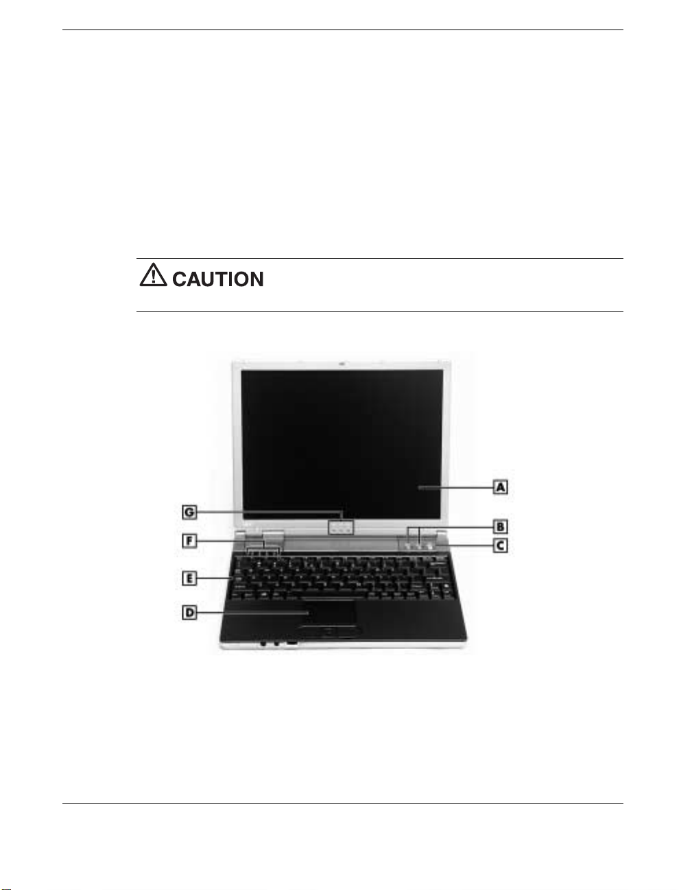
The base uni t of your NEC Versa notebook offers the features shown in the following
figure. Feature descri ptions follow the figure.
After extended use, the surface of the base unit, below the
keyboard, might becom e hot to the touch.
LCD pa nel and base unit
A
– LCD Panel
B
– Shortcut Buttons
C
– Power Button
D
– NEC VersaGlide Touchpad
1-4 Introducing the NEC Versa
E
– Keyboard
F
– Drive and Keyboard Status LEDs
G
– Power and E-Mail Status LEDs
Page 14

LCD Pan el — Provides a high -resolution display for sharp, effe c tive visuals on
your N EC Versa notebo ok. You c an use keyboard key combina tions to incr e ase and
decrease LCD brightness and to toggle between video modes (see “Keyboard
Panel”).
Power and E-mail Status LEDs — Indicate power and e-mail status. Power LEDs
indicate whether the system is running on AC power or battery power and indicate
battery status. The e-mail LED notifies you when you have a new e-mail message.
These LE Ds also appear on the top of the not ebo ok f or viewing s tatus when the
LCD panel is closed. For detailed information, see th e section, “Status LEDs”.
Power Button — Powers th e system on and off (s ee the secti on , “System
Controls”).
Shortcut Buttons — Launch your browser or your e- mail application ( s e e t he
section , “System Controls”).
NEC VersaGlide™ Touchpad — Work s lik e a s tandard comp u ter mouse. Sim pl y
move your fingertip over the Ver saGlide to control the position of the cur sor. Use
the selection button s below the VersaGlide to select menu items. See “NEC
VersaGlide Touchpad” in Chapter 2 for information about using th e VersaGlide and
for cus tomizing Ver s aGlide settings.
Keyboard — Provid e s 83 keys with the stan da rd QWERTY-key l ayout . (Models
pur cha s ed ou tside of th e U.S. and Canada shi p wi th cou ntry-specific keyboard
layouts.) See “Keyboard Panel” for information about key functions.
Drive and Keyboard Status LE Ds — Keep you informed of the current op er ating
status of the hard drive and keyboard functions (see the section, “Status LE Ds”).
Introducing the NEC Versa 1-5
Page 15
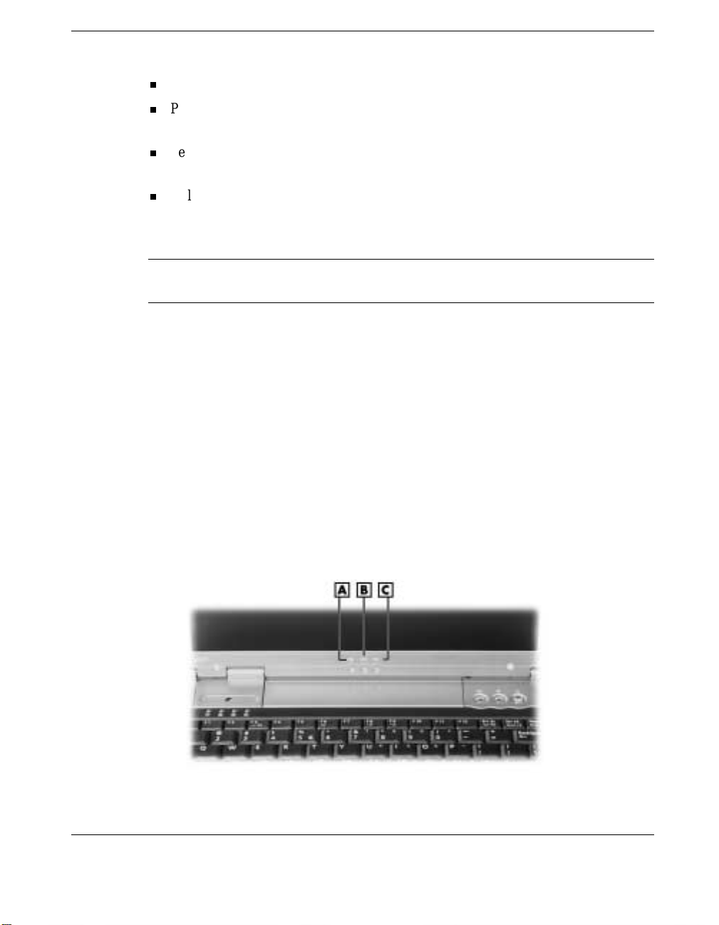
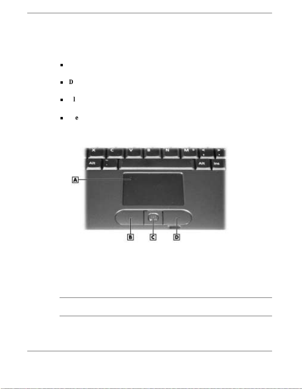
System Controls
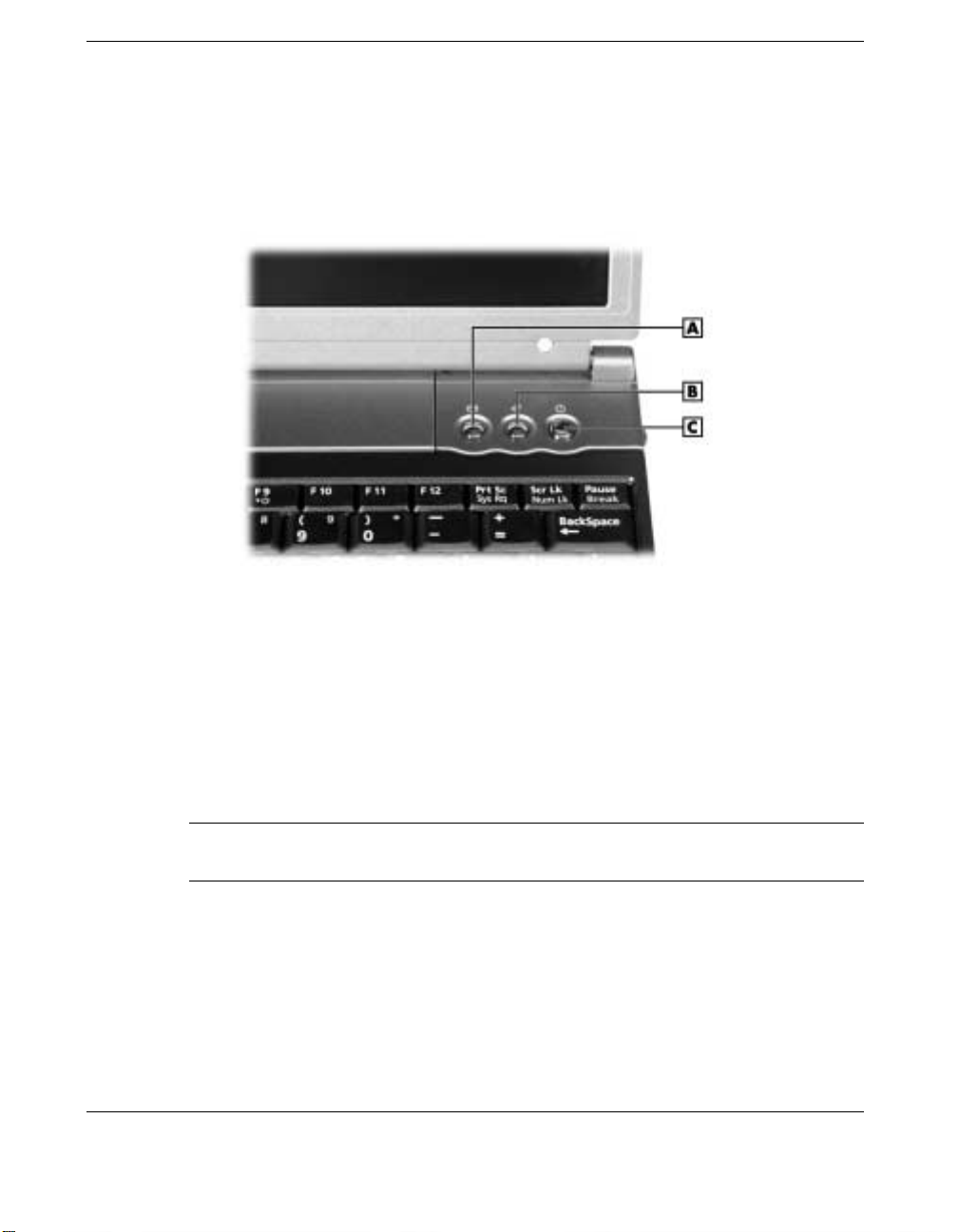
System controls let you select speci fi c system operations. In the Versa E120 Da yLi te,
syste m cont rols includ e the power button and two shortcut buttons.
System contr ol bu tto ns
A
– Shortcut Button (e-mail)
B
– Shortcut Button (Internet)
C
– Power Button
Power Button
The power button is a “smart” switch. You can configure the power button to go into
Standby or Hibernate mode or to power off wh e n pres s e d. With W i ndows XP, you can
also configure the power button to go into a “Do nothing ” or “Ask me what to do”
mode of operation.
Note
managing system power resources.
The default power button operation is to shut down . Under normal operation, the
syste m per forms a smooth shutdown when you pres s the powe r button.
1-6 Introducing the NEC Versa
See “Windows Power Management” in Chapter 4 for information about
Page 16
Use the power button in the following ways:
Press the power button to power on.
Press the power button to resume fr om a Win d ows or Hibernate mode and proceed
with nor mal operation.
Per form the function as s e t in the Adva nced t ab of th e Windows Power Option
Properties dialog box.
Hold the power button in place for 4 or more seconds to initiate a power override
(po wers off t he system). Only use this op tion if you c annot power off your system
from the Start menu.
Note
power button and hold it in place approximately 4 to 5 seconds until the system powers off.
Shortcut Buttons
The Versa E120 DayLite system has two shortcut buttons that you can configure to
launch your defau lt Int er net br owser an d your default e-mail a pplication . See “OneTouch Start Button Settings Utility” in Chapter 4 for information about con figuring the
buttons.
Status LEDs
The Versa E120 DayLite system uses st atus LEDs marked with icons to communicate
the st atus of system po wer and system operations ( s ee the following figures and
descriptions).
If you are unable to power off the system, use the power override. Press the
Power and e- mai l st atus LED s
A
– Power LED
B
– Battery St atus L E D
C
– E-mail Notifi cation LED
Introducing the NEC Versa 1-7
Page 17

Drive and keyboard status LEDs
A
– Drive Activity L ED
B
– Caps Lock LED
Power Status and E-mail LEDs
Power Status LEDs ind icate whether the system is run n ing on AC power or ba ttery
power, and indicate battery status as follows.
Power Status LED — Lights to indicate the followin g status:
— Light s green when the s ystem power is on .
— Blinks green when the system is in Standby mode.
— Lights yellow (blinks when in Standby mode) to indicate that battery power is at
10% capacity or less.
— Light s amber (blink s when in S tandby mode) to indicate th at battery power is at
4% capacity or less.
The Power Status LED is off when system power is off or when the system is in
Hibernate mode (see “Hibernate” in Chapter 4).
Battery Charging LED — Ligh ts to in dicate battery char ging activity.
— Light s amber when th e primary batter y is charging. Blinks amber to indicate an
error. The primary battery is installed in the battery bay.
C
– Scroll Lock LED
D
– Num Lock LED
— Light s green when the secondary batt ery is charging. Blinks gr een to indicate an
error. The secondary (optional) batter y connects to the bottom of the not ebook
and covers most of the bottom of the unit.
1-8 Introducing the NEC Versa
Page 18
E-mail Notification LED — Lights when new e-mail i s received.
Note
The system also has Power, Battery Charging, and E-mail notification LEDs
on the top rear of the LCD panel. You can see these LEDs when you are behind your
notebook computer or when the LCD panel is closed.
Drive and Keyboard Status LEDs
Drive and keyboard status LEDS include the following LEDs (see the previous figure
for the location of these LEDs):
Drive Activity LED — Lights when the NEC Versa accesses the hard disk.
Caps Lock LED — Lights when caps lock is in effect.
Scroll Lock LED — Light s wh en s croll lock is in eff ect .
Num Lock LED — Lights wh en num lock mode is active. In this mode, you can use
the embedded numeric keypad.
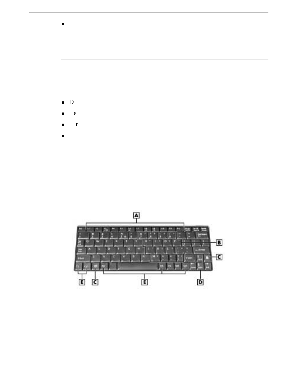
Keyboard Panel
The NEC Vers a E120 DayL ite keyboard has a sta ndard QWERT Y -key layou t. (M odels
shipped outside the U.S. are equipped with country-specific keyboard layouts.)
Keyb oard fe ature s are desc ribed after the figure.
Keyboard
A
– Function Keys
B
– Numeric Keypad
C
– Windows Keys
D
– Cursor Control Keys
E
– Control Keys
Introducing the NEC Versa 1-9
Page 19
Function Keys — Twelve function keys, F1 through
F12
, are avail able on the NEC
Ver s a keyboard. Functi on keys are application-driven, so t heir fu ncti on varies
accord ing to the app lication in us e. S ee the specific applicat ion’s user guide for
information about how each function key works within the application you use.
Fn
The function keys wor k together with the
key to activate special preprogrammed
functions. The followin g function key combinations ar e pre-programmed for the
NEC Versa E120 DayLite.
Fn-F3
Toggles the video mod e be tween LCD only, CRT only, or S i multaneous
—
mode (both LCD and CRT).
Fn-F5
— Zooms the s creen in or out sl ightly.
Fn-F6
Fn-F8
Fn-F9
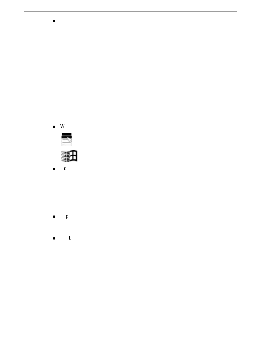
Windows Keys — Use the following two keys to facilitate your work.
Toggl es the system beep o ff and on.
—
— Increases LCD brightness (ei ght settings).
— Reduces LCD brightness (eight settings).
Shortcut/Application key – provides quick access to shortcut menus.
(This key acts like a righ t mouse button.)
Floating Window key – d isplays th e S tart menu.
Numeric Keypad — Pressing
Fn-Num Lk
on the keyboard activates the numeric
keypad numbers and funct ions pr i nted in yellow on top of the keys.
The keypad lets you typ e numbers and mathematical operands (+, –) as y ou would
on a calculator. Th e keypad is ideal for entering long lists of numbers.
When you press
Fn-Num Lk
again, the keys revert to their norm al functions as
typew riter keys.
Typewriter Keys — Typewr iter keys (also called alphanumeric keys) are used t o
enter text and characters. Keys with yellow print on them behave differently when
combined with control keys, th e
Fn
key, or when
Num Lk
is active.
Control Keys —
Ctrl, Alt, Fn
keys to ch ange their functions. To u s e control keys, p ress and hold the control key
whil e pressing an other key. For example, “Press
Ctrl
key an d type the letter C. Key combinations work specific to the application
you are running.
1-10 Introducing the NEC Versa
, and
Shift
are controls used in conju nction with other
Ctrl C
” means to ho ld do wn the
Page 20
Cursor Control Keys — Cursor control keys let you position the cursor on the
screen where you wan t. On the screen, the cursor is a blinking under line, block, or
verti cal bar depending on the application. The cursor ind icates wher e the next text
typed is inser ted.
Note
a halt in system operation. Make sure you have a printer connected to the system
before using the
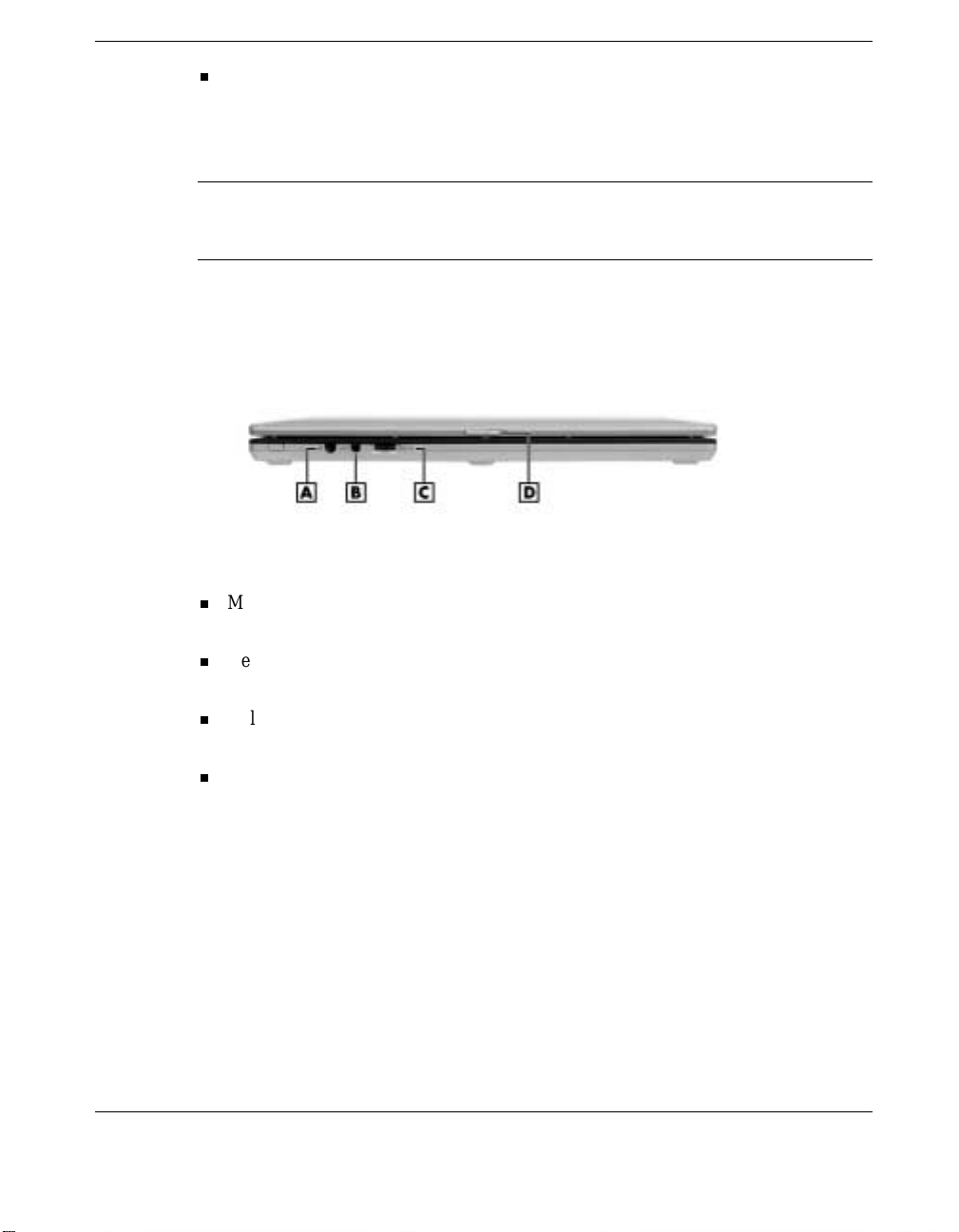
Front Featur es
The features on the front edge of th e s ystem are described after the figure.
A
– Microphone In Jack
B
– Headphone/External Speaker Jack
Micr ophone In Jack— All ows you to connect an external microphon e for
monophon ic recording or amplification through the unit.
Headphone/Ext ernal Speak er Jack — Lets you plug in stereo headph ones or
powered speakers. P lugging in head phones disa bl es the built-in s ystem speakers.
Volume Control — Allows you to control the sp eaker volume through the thu mb
wheel.
Pressing the
Prt Sc
Prt Sc
key without a printer connecte d to the system can cause
key.
Front features
C
– Volume Control
D
– LCD Panel Latch
LCD Pan el Latch — Slide the latch to the ri ght to open the N EC Versa E120
DayLite n otebook.
Introducing the NEC Versa 1-11
Page 21
Around the Back of the System
You’ll find system ports for connecting your NEC Versa E120 DayLite to AC power
and optional devices (like a prin ter, a storag e d evice, or ext er nal monitor) on the back
of your NEC Ver sa. The ports are described after the figure.
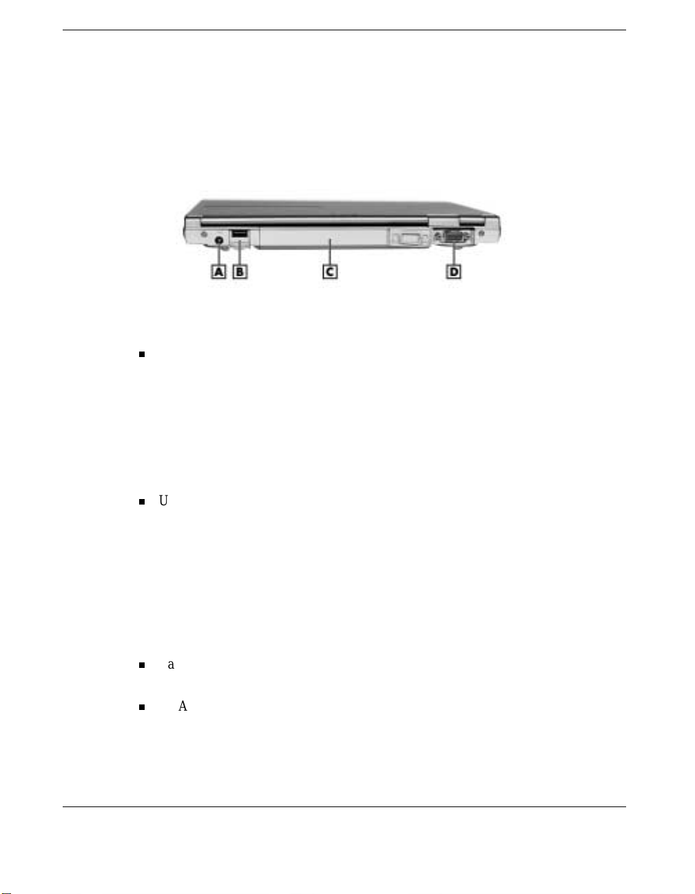
Back featur es
A
– DC Power Port
B
– USB Port
DC Power Port — Lets you attach th e NEC Versa notebo ok to a D C power source,
C
– Battery Bay
D
– VGA P ort
such as th e A C power adapter that comes with your system. The AC power adapter
plug s into an AC power source and into the DC power port on the rear of the NEC
Versa notebook.
The AC power adapter uses a standard 115-Vac or 230-Vac grounded power
source. Keep the syst em connected to the AC power a da pter and an AC power
source wh enever possible to keep the battery pack and internal CMOS batter y
charged.
USB P o rt — Allows you to easily and conveniently connect a USB-equipped
peri pheral device to t he NEC Versa. There are many USB devices available (for
examp le, storage device s , printers , k eyboards, mous e, monitors, s can ners, and
digital cameras) to expand system capabilities. The NEC Versa E120 DayLite has
two additional USB ports on the right side of the system (see “Aroun d t he Right
Side of the System”).
Connect your external USB CD-ROM dr ive to one of the USB ports. See “USB
Devices” in Chapter 5 for addition al information about adding USB devices t o t he
NEC Versa notebook.
Battery Bay — Contains the system’s standard Lithium-Ion (Li-Ion) primary
battery.
VGA Port — Use this 15-pin port to attach an external monitor to your NEC Versa
notebook . With an ext er nal monitor attached, u s e th e k eyb oa rd function key
Fn-F3
combination
to toggle between LCD, C RT, and Simultan eou s LCD/CRT
video modes (see “Ke yboard Panel ”).
1-12 Introducing the NEC Versa
Page 22
Around the Left Side of the System
The left side of your NEC Versa E120 DayLite provides the features shown in the
followin g figure. Featur e descriptions follow the figure.
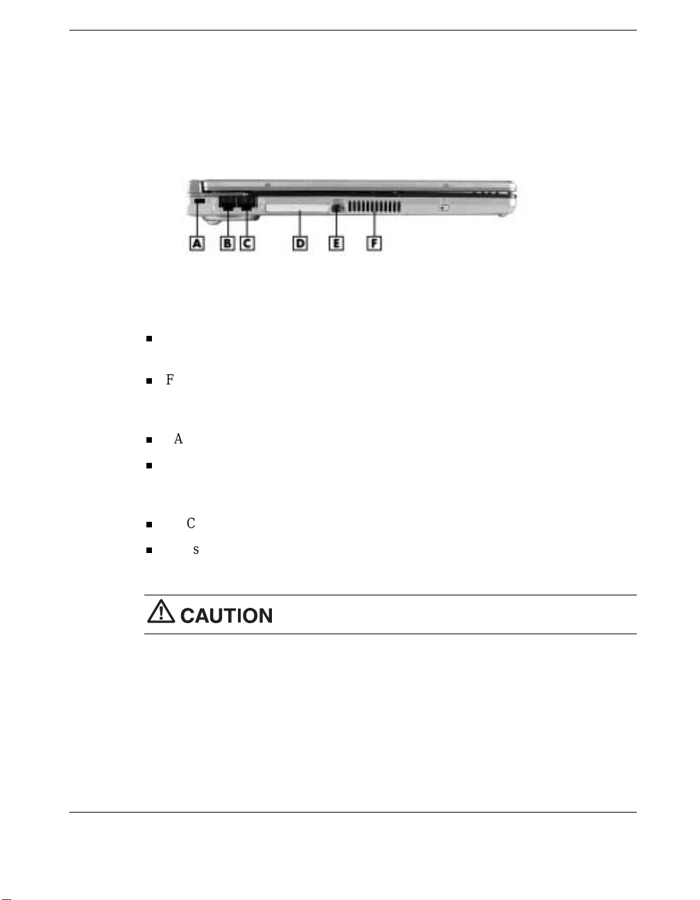
Left-side features
A
– Kensington Lock Slot
B
– Fax/Modem Port
C
– LAN Port
Kensington® Lock Slot— This slot allows you to attach a Kensin gton secur ity lock
D
– CF Card Slot
E
– CF Card Eject Button
F
– Vents
or other compatible lock to secure the notebook from theft.
Fax/Modem Port — Use this p or t t o connect the syst em’s internal V.90 fax/modem
to an analog telephone line for access to fax machine emulation, telephone
answer ing machin e functions, an d the Internet.
LAN Port — Use this p or t to connect the system to a local area network ( LA N).
CF Card Slot — Allows you to insert a Type I or Type II CompactFlash™ (CF)
Card into this slot for connection to a wide variety of options, such as flash
memory, personal data assistants (PDAs), and video cameras.
CF Card Eject Button — Press this button to release a CF Card.
Vents — Allow your system t o c ool properl y and maintain a s afe operatin g
environment.
Do not block the ven ts while the NEC Versa is in use.
Introducing the NEC Versa 1-13
Page 23
Around the Right Side of the System
The right side of the NEC Versa E120 DayLit e offers the feature s shown in the
follo wing figure. These features are descr ibed after the fi g ure.
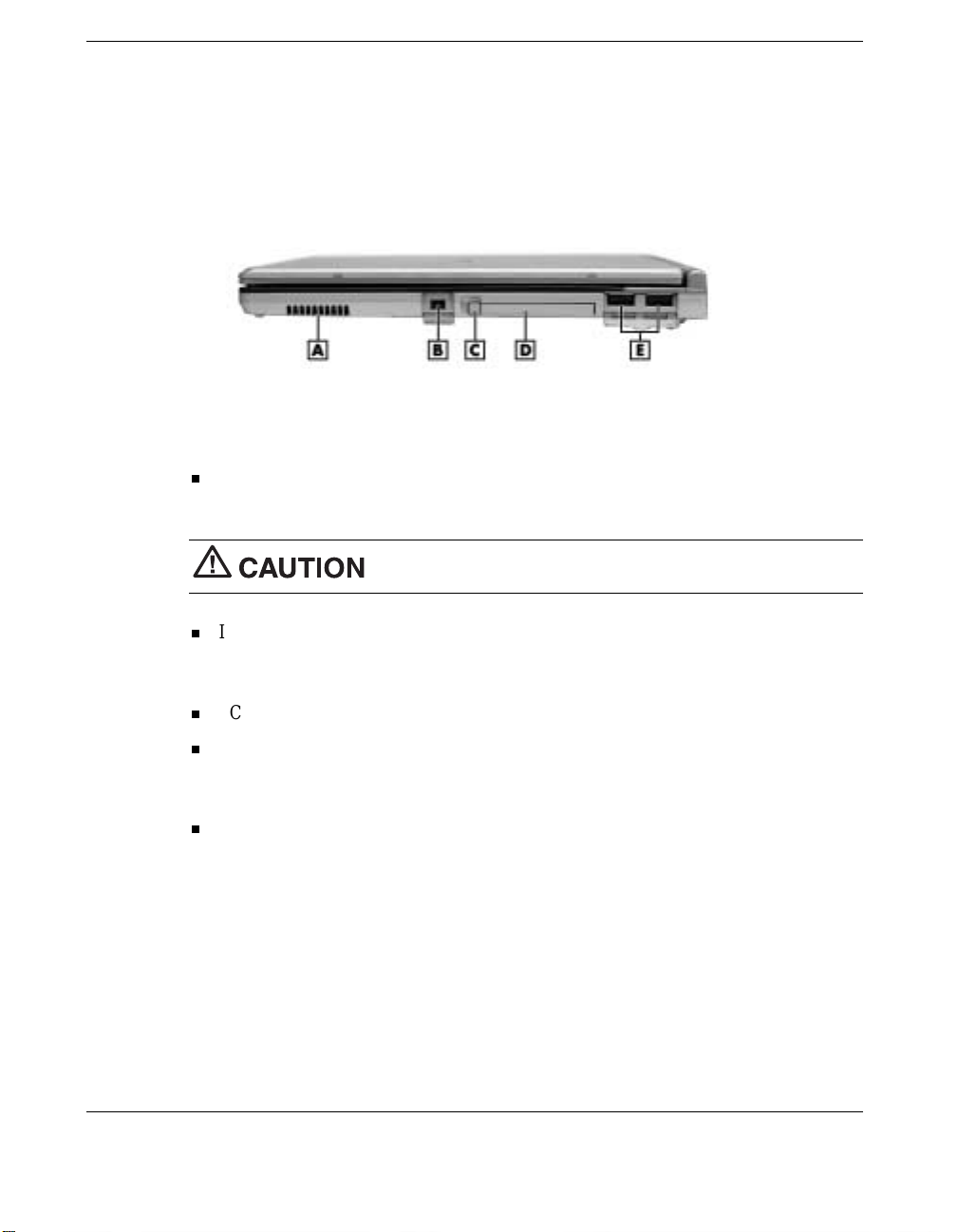
Right side features
A
– Vents
B
– IEEE 1394 Port
C
– PC Card Eject Button
Vents — Allow your system t o c ool properl y and maintain a s afe operatin g
D
– PC Card Slot
E
– USB Ports
environment.
Do not block the ven ts while the NEC Versa is in use.
IEEE 1394 Port — Use t hi s port to daisy chain up to 63 IEEE 1394 devices to your
system. IEEE 1394 devices support Plug and Play connectivity for transfer rates of
up to 400 Mbps.
PC Card Eject Button — Press this button to release a PC Card.
PC Card Slot — Allows you to insert a Type I or Type II PC Card into this slot for
connection to a variety of options such as flash memory, SCSI adapters, LAN
connections, and hard drives.
USB P o rts — Allows you to easily and conveniently connect a USB-equipped
peripheral device to each of these ports. The NEC Versa E120 DayLite has a third
USB port at the rear of the system. See “Ar ound the Back of the S ystem” for
additional information about USB ports.
See “USB Devices” in Chapt er 5 t o connect the ext ernal CD-ROM dr ive that comes
with your NEC Versa n otebook and to connect other USB devices to th e system.
1-14 Introducing the NEC Versa
Page 24
Around the Bottom of the System
The bottom of the NEC Versa E120 DayLite offers the features shown in the following
figure. Feature descri ptions follow the figure.
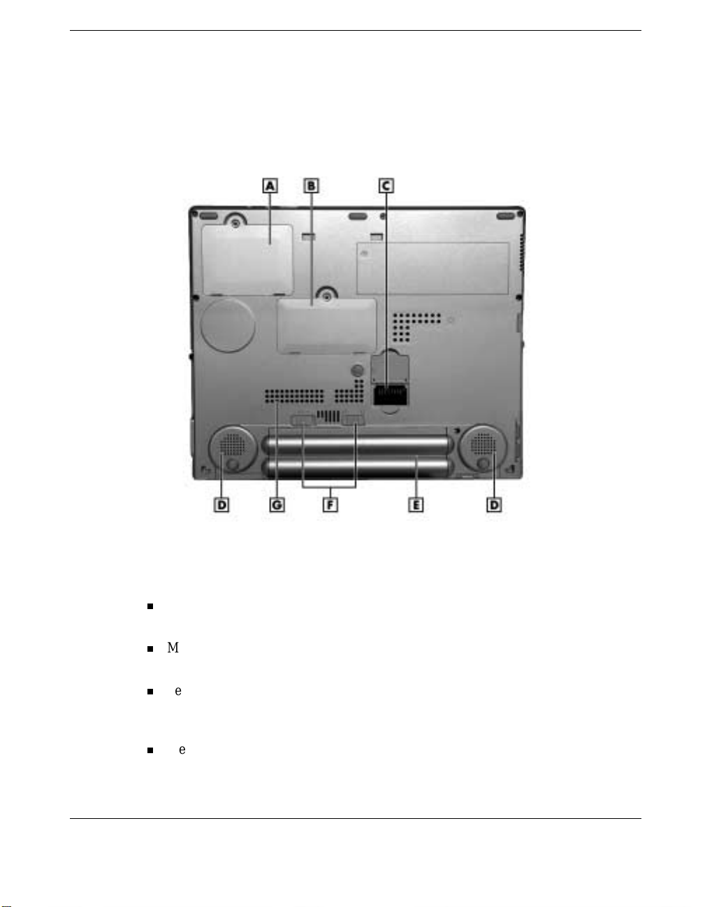
Bottom features
A
– Mini PCI Module Bay
B
– Memory Module Bay
C
– Secondary Battery Connector
D
– Ster eo Speakers
Mini PCI Module Bay — Contains a socket for the installation of an opt ional Mini
E
– Primary Bat tery
F
– Battery Lock/Release Bu ttons
G
– Vents
PCI module (when available).
Memory Module Bay — Contains a socket for memory upgrade. See Chapter 5 for
detailed memory upgrade information.
Second ary Batter y Bay Connector — Allows t he connection of a secondary lithium
ion (Li-Ion) battery pack. See Chapter 2 for information about installing, charging,
and using the second ary batter y.
Ster eo Sp eakers — Provide stereo sound for your multimedia presentations or
listening pleasure. The built-in sound system also supports 3D sound, which
simulates the latest surround-sound technology.
Introducing the NEC Versa 1-15
Page 25

Primary Battery — Comes with the system. See Chapter 2 for information about
inst alling, char g ing, and using th e pr imary battery. See “Windows Po w er
Management” in Chapter 4 to fully utilize battery power in your NEC Versa
notebook.
Battery Lock/Release Buttons— Press the buttons towards each other to remove the
primary battery pack. See Chapter 2 for detailed battery installation information.
1-16 Introducing the NEC Versa
Page 26

Getting Started
NEC VersaGlide Touchpad
Power Sources for Your NEC Versa
AC Adapter
System Batteries
Using the Primar y Batt er y
Using a Secondary Battery
System Care
2
Page 27
NEC VersaGlide Touchpad
The NEC VersaGlide touchpad is an easy way to control th e cursor with your finger.
Lightly glide your fi nger across the NEC Versa G lide and the cur s or follows. Use t he
VersaGlide touchpad as follows.
Single tap the touchpad
— equivalent to a single click of the primary mouse
button.
Double tap the touchpad
— equivalent to a double click of the primary mouse
button.
Click
and
hold,
then
your finger across the VersaGlide touchpad —
drag
equivalent to a click and drag of the primary mouse button.
the scroll button up or down to scroll your document or screen.
Press
VersaGlide features
A
– NEC VersaGlide touchpad
B
– Left Button
Try all of the VersaGlide featur es and decide wh ich you prefer. If you find th e double
tap or any of the other features difficult to use, go to the next section for general
direct ions about a d justing the VersaGlide properties.
Note
the double-tap capability.
2-2 Getting Started
C
– Scroll Button
D
– Right Button
If you inst all another m ouse driver over the shipping default, you mig ht lose
Page 28

VersaGlide Adjustments
The NEC Vers aGlid e offers a number of options that let you cus tomize how it
function s. The options let you con tr ol the cur sor speed, select button orientation, enable
or disable tapping, define auto jumps, enable easy-scrolling, and configure gestures to
initiate selected functions by tapping in a designated area of the touchpad.
To access these options, locate the Win dows Control Panel and double click the mouse
icon. Use the context-sensit ive help to learn more about each option. Select the opti on ,
F1
and then press
to access the context sensitive help.
VersaGlide Tips
Follow t hese basic t ip s while workin g :
Use a light touch on the VersaGlide surface.
Set up the NEC Versa notebook with your keyboa rd and VersaGlide at a
comfortable height. Keep your forear ms parallel to the floor. Your wrists sh ould be
relaxed and straight.
While u s in g the keyboar d an d VersaGlide, keep your shoulders and arms as relaxed
as possible.
Take regular breaks from the computer to rest your eyes. Perform stretching
exercises to relax your fingers, hands, wrists, forearms, and shoulders.
See Appendix A, “Setting Up a Healthy Work Environment,” for more information.
Power Sources for Your NEC Versa
Operate your NEC V ersa just about anywhere using one of the followin g power
sources:
the AC ada pter connected to an electrical wall ou tlet (using AC p ower )
battery power:
— 4-cell Lithium Ion (Li-Ion) primar y battery
— with or with out the optional 8-cell secondary battery that installs on the bottom
of the NEC Versa.
Read th e following section s for specific information about using th e NEC power
sources.
Getting Started 2-3
Page 29
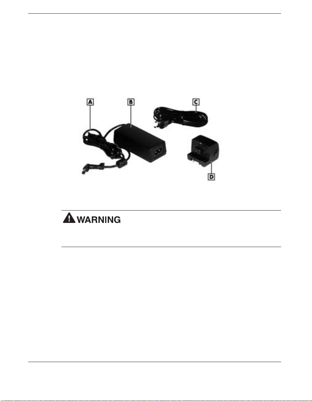
AC Adapter
Use th e AC ad apter and power cable or wall pl u g th at comes with your NEC Versa
notebook to run your computer on a l terna t ing current ( AC) power or to recharge t he
battery.
Keep the adapter connected when ever possible. The AC adap ter charges the battery
when it is connected, whether the NEC V er s a n ot ebook is powered on or off.
AC adapter
A
– AC Adapter Cable
B
– AC Adapter
adapter has no user-replaceable or serviceable parts inside. Dangerous voltage in the
AC adapter can cause serious personal injury or death. The AC adapter is intended for
use with a computer and must meet EN609050 standards.
2-4 Getting Started
C
– Power Cable
D
– Wall pl u g
Do not attempt to disassemble the AC adapter. The AC
Page 30
Connecting the AC Adapter
Note
wher e you are using it. Contact the local dealer to purchase the co r rect power cable if it
differs from the one provided.
The AC power cable type that your system uses depends on the c ountry
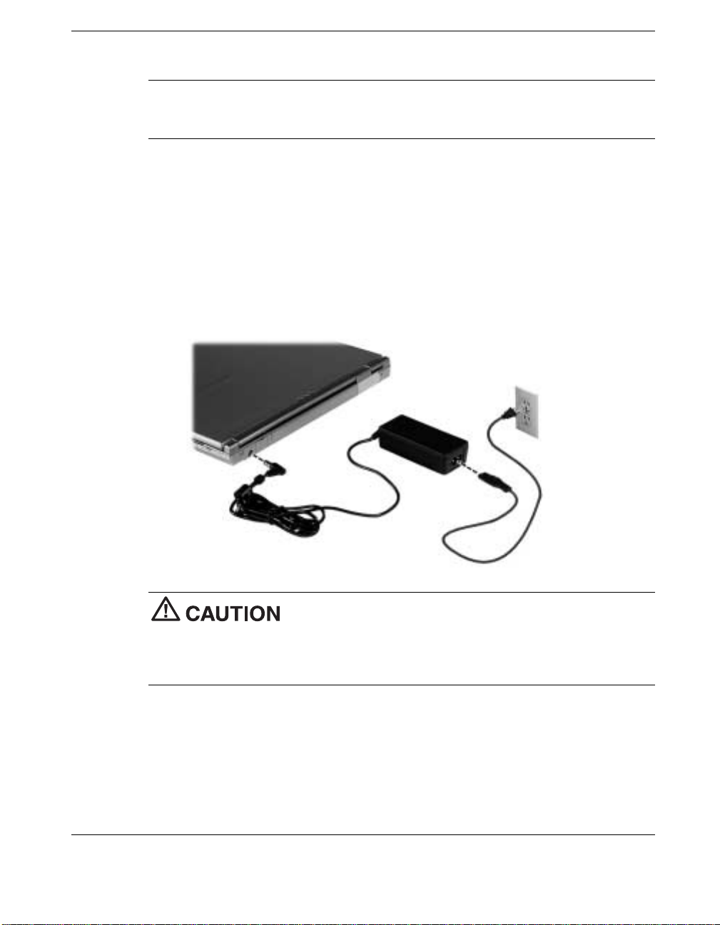
Connect the AC adapt er as follows.
1.
Connect the AC adapt er cable to the power port at the rear of your NEC Versa
notebook.
2.
Plug on e end of the AC power cable into the A C a dapter and th e oth er end into a
properly grounded 120- or 240-volt , 50- or 60-Hz wall outlet.
Connecting the AC adapter
Do not cover or place objects on the AC adapter. Keeping the
adapter clear of objects lets the adapter cool properly during use.
Only use the AC adapter that comes with your NEC Ver s a E120 DayLite. Although other
adapters look similar, using them can damage your system.
Getting Started 2-5
Page 31

Note
AC adapter instead of the AC power cable. Connect the wall plug to the AC adapter and
to the properly grounded 120- or 240- volt, 50- or 60-Hz wall outlet.
You can connect the wall plug that comes with the NEC Versa notebook to the
Using the AC adapter wall plug
Powering On Your System
Power on the system as follows.
1.
Locate the latch on th e front of the LCD panel, slide it to the right, an d r aise the
panel (see “Front Features” in Chapter 1).
2.
Loca te the power button and press it to turn on syste m power. For additional
information about power button features and power LED status, see Chapter 1,
“Introducing th e NE C Versa.”
2-6 Getting Started
Page 32

System Batteries
Your NEC Versa notebook is equipped with a primary lithium ion battery that helps to
prevent data loss. In addition, you can install an optional secondary lith ium ion battery
pack on the bottom of your NEC Vers a to give you more on-th e-go power.
Primary Battery
The standard lith ium ion (Li-I on) battery provides the main power sour ce when you are
opera ting the NEC Ver s a n ot ebook on batt ery power. Your s ystem comes with a 4 - cell
lit hium ion battery in th e battery bay on the bottom of your system. See Append ix B for
battery specification s.
For information about installing or removing the primary battery, see the section,
“Replacing the Battery ” later in this chapter. For more infor mation about the primary
battery see the section, “Using th e Primary Battery.”
Note
in your NEC Versa notebook.
See “Windows Power Management” in Chapter 4 to fully utilize battery power
Secondary Battery
You can install an optional secondary lithium ion battery on the bottom of your NEC
Versa notebook. This is a very thin battery pack that covers the bottom of the unit.
Attaching a second fully charged battery allows you to work longer while you are away
from an A C power source.
For mor e information about the secondary battery, see the sect ion, “Using the
Secondary Battery” later in this chapter. For infor mation about installing a secondary
battery, see “Secon dary Battery” in Chapter 5.
Getting Started 2-7
Page 33

Using the Primary Battery
The NEC Versa notebook comes with a rechargeable 4-cell lithium ion (Li-Ion) battery
that’s easy to install and remove.
Primary battery
To prevent accidental battery ignition or explosion, adhere to
the following:
Keep the ba t tery aw ay from extreme heat.
Keep metal objects away from the battery connectors to prevent a short circuit.
Make sure the bat t ery is properly installed in the battery bay.
Read the precautions printed on the battery.
Determining Battery Status
Your NEC Versa system provides tools to help you keep track of the main (and an
optional ) battery’s power level. If your system is con figured (default setting) to display
the Power icon on the taskbar, the followin g taskbar icons appear:
An elect r ical plug appears when th e syst em is connected to an AC power source.
A batt er y icon appear s when the system i s n ot connected to a n AC power source.
Use th e s ystem’s power meter to determine battery status. Access the system’s power
meter in the following ways:
Move the cursor over the Pow e r icon on the taskbar to display the r e m ainin g battery
power for the system’s primary battery.
Right click th e Power icon on the taskbar to open the power meter or to adjust
power properties.
Double click the Power icon on the taskbar to display the remaining power for both
the primary an d optional secondary battery (if installed).
2-8 Getting Started
Page 34

Go to Start, Settings, Control Panel, and doubl e click the P ower Management icon
in Windows XP or the Power Options icon in Windows 2000. Select the Power
Meter tab .
Low Battery Status
When battery power is low (10% or less), the power LED lights yellow (blinks in
Standby mode). When battery power is very low (4% or less), the power LED lights
amber (blinks in Standby mode). When your system is in a low battery status, do one of
the following:
Power off the system, remove the spen t battery, an d replace it with a fu lly charg ed
battery.
Leave the spent batt ery in the system and connect your N EC Versa notebo ok to the
AC adapter and a wall outlet.
Returning the Battery to its Normal State
If batter y pe rformance drops, for example, you experience shorter work times, try one
of the following procedures to improve battery performance:
Remove a n d reinstall the battery in your NEC Ver sa n ot ebo ok and full y r ech arge
the battery (to 100%).
Refresh the battery using the Battery Refr esh function in the Exit men u of the BIOS
Setup utility (see “Exit Menu” in Chapter 3).
Extending Battery Life
While on the road, it is important to be aware of the simple things you can do to extend
the life o f t he system’s main battery:
Keep the brightness setting low. Use the
the br ightness.
Turn off the system when you finish usin g it.
In addition, NEC Solution s recommends that you always operate your system on AC
power wh en using any external device.
Fn-F8
and
Fn-F9
function keys to contr ol
Getting Started 2-9
Page 35

Battery Handling
Keep the following in mind when removing or replacing a battery.
Use only the battery designed for your NEC Versa notebook. Mixing other
manufacturers’ batteries, or us i ng a combinat ion of very old an d new bat teries can
dete riorate bat tery an d e quipm ent per forman c e.
Turn off po w er to the system a ft er use. Keepi n g s ystem power on can d egr ade
battery performance and shorten batter y life.
Clean the battery connectors with a dry cloth when they get dirty.
Keep the battery out of t he reach of chi ldren.
Replacing the Primary Battery
The following symptoms indicate that battery life is nearing an end. Replace batter ies
that display these symptoms.
Shorter work times.
Disc oloration, warping.
Hot to the touch.
Str a nge odor.
Replace t he battery installed in your NEC Versa s ystem as follows .
computer. Installing another manu facturer’s battery or using a combination of very old
and new batteries can deteriorate batt ery and equipment performance.
Note
1.
2.
To replace a secondary battery, see “Secondary Battery” in Chapter 5.
Save your files, ex it Windows, and turn off system power.
Close the LCD panel an d tur n over the system.
2-10 Getting Started
Only use batteries t hat are designed for your NEC Versa
Page 36

3.
Remove the pr imary batter y as follows.
Slide the battery lock button to the left release position.
Slide the release button to the right and hold firmly.
While holdin g the release button, slide the battery out of the battery bay.
Removing the primary battery
A
– Battery Release Button
B
– Battery Lock Button
C
– Primary Bat tery
Getting Started 2-11
Page 37

4.
Insert the new battery as follows:
Make sure the right battery lock button is in the unlocked position (see the
previous figure).
Align the battery con nector an d ta b with the battery bay slot and con nector.
Align the grooves on the sides of t he battery with the rails in the batt ery bay.
Slid e the battery into the battery bay. Press the batter y into the connector to
secure it.
Press the battery lock button to the right locked position.
Installi ng th e pri m ary ba ttery
A
– Battery Bay Slot
B
– Battery Bay Connector
C
– Battery Bay Rail
5.
Turn the system over.
2-12 Getting Started
D
– Primary Bat tery
E
– Batt ery Gro ove (left side)
Page 38

Charging the Battery
Charge the primary battery and optional secondary battery by simply conn ecting your
NEC Ver sa s ystem to an AC power source. To mon itor the charg in g activity, observe
the battery charging LED on the fr ont of the system. The battery charging LE D lights
as follows:
Lights amber when the primary bat tery is charging.
Blin ks amber if the pri mary batter y en counters an error while charging.
Light s green when the s econdary batt ery is charging.
Blin ks green if the secon dary battery encounters an error whi le charging.
Battery Precautions
To prevent accidental battery ignition, rupture, or explosion, adhere to the following
precautions.
incorrectly r eplaced. Replace only wit h the same or equivalen t type recommended
by the manufacturer. Discard used batteries according to the manufacturer’s
instructions.
To avoid personal injury and proper t y damage, read these battery precautions on
handling, charging, and disposing of Li-Ion batteries.
Keep the battery away from heat sources including direct sunl ight, open fires,
microwave ovens, and high-voltage cont ainers. Temperatures over 140º F
(60ºC) may cause damage.
Do not drop or bump the battery.
Do not disassemble the battery.
Do not solder the battery.
Do not puncture the battery.
Do not use a bat t ery that appears damaged or deformed, has any rust on its
cas ing, is disco l ored, overheats, or emits a foul odor.
Keep the battery dry and away from water.
Keep metal objects away from battery connectors. Metal objects in contact
with the connectors can cause a short circuit and damage.
If the battery leaks:
If the battery leaks onto skin or clothing, w ash the a rea immediat ely wit h
clean water. Battery fluid can cause a skin rash and damage fabric.
If b atter y fluid gets into eyes , DO NOT rub; ri nse with clear w ater immediately
and consult a doctor.
Tak e extra precautions to keep a leaking battery away from fire. There is a
danger of ignition or explosion.
There is a danger of explosion if the battery is
Getting Started 2-13
Page 39

Precautions for Recharging the Battery
Adher e to the following precautions when recharging the primary or second ary battery.
Char g e th e battery for the specified charge time only.
During charging , k eep the environ mental tem p er ature between 32°F and 104°F
(0°C to 40°C).
Using a Secondary Battery
An optional secondary 8-cell battery is available for your NEC Versa n otebook. This
battery installs on the bottom of your computer. See “Second ar y Batt er y” in Cha p ter 5
for installation informat ion.
Use th e s econdary batt ery in addition to the primary battery to extend th e amount of
time you can run your system on battery power .
Do not run the system on secondary battery power without the
primary battery in place.
The connector in the primary battery bay should not be exposed. An exposed connector
can cause a danger if it is accidentally touched or if it connects with a metal object
during system operation.
Also see:
“Using th e Primary Battery” earlier in this chapter for general information about
handling system batteries.
The pr ecautions in the section, “Using the Primary Battery” for information that
appli es to the safe use of t he secondary ba ttery.
2-14 Getting Started
Page 40

System Care
The NEC Vers a E120 DayL ite n otebook c omput e r is designed t o be a dura ble,
dependable system built for extensive use and travel. Follow these guidelines to
maintain the condition and performance of your computer.
under the following conditions:
The power cord is damaged or frayed.
Liquid spills on or into the NEC Versa notebook.
The system is dr opped or the casing is damaged.
Precautions for System Use
Follow these precau tions when using your NEC Ver sa com puter and A C adapter.
Avoi d dropp i ng or bu m ping the computer or the AC adapter.
Do not stack heavy object s on the compu ter, the AC adap ter, or the batteries.
Avoi d moving the NE C Versa notebook during system operation, especiall y wh ile
the har d di s k , di s k ette drive, or other drive is bei n g accessed.
When u s in g th e A C ad apter, make sure the power s ource falls within the system ’s
compatible range of 100-240 volts and 50 or 60-Hz, AC. Never use the AC adapter
if the voltage falls outside of this range. (Watch for this when traveling to oth er
countries.)
Turn computer power off before attaching or removing non-plug and play devices
that are not warm- or hot-swappable.
Do not push any foreign objects into the NEC Versa bays, connectors, and slots.
Do not set the computer on top of a magnetized ar ea. Doing so can d estroy the data
on you r hard disk drive. (S ome airline tray tables are ma gneti c .)
Avoid using the computer or AC adapter for extended periods in direct sunlight.
Do not use the system in humid or dusty environments.
Turn comp uter power off before cleaning it.
Avoid ex p osing the NEC Versa notebook or A C adapter to extr eme changes in
tem perat ure or hu midity. If it is unavoid able, a llow your NEC V ersa not ebook to
adjust to room temperature before use.
When cl eaning the system , use a soft, cl ean, dry cloth . Avoi d wi p ing the dis pl ay
surface with abrasive material, including rough fabric. Do not use a cleaning
solution ; this may damage the notebook’s magnesium case.
If the AC adapter becomes extremely hot, unplug the adapter and let it cool.
Immediately turn off and unplug the NEC Versa notebook
Getting Started 2-15
Page 41

Storage Requirements
Store the comput er and AC adapter in an environment that meets th e fol l owing
conditions:
or f alls (for example, w hen you m ove the s ystem f rom a col d place to a warm place)
vapor condenses inside the system. Turning on the syst em under this condition can
damage the internal system com ponent s.
Before turning on the system, wait until the system’s internal temperature equalizes with
the new environment and any internal moisture evaporates.
Main tain storag e temperatur es bet w een -4°F and 104°F (-20°C and 40°C).
Keep the storage ar ea free from vibration and magnetic field s.
Keep the system and its com p onents awa y from organic solvents or corr osive gases.
Avoid l eaving the system and its components in dir ect sunligh t or n ear heat sour ces.
Routine Cleaning
Clean or dust your system as follows:
If the temperature of the NEC Versa notebook suddenly rises
cleaners that contain caustic materials on the NEC Versa computer.
These cleaners are usually high in alkalinity, which is measured in pH. Using these
cleaners can harm the magnesiu m surface .
LCD scr een — Carefully wipe the LCD screen with a soft cloth or a screen wipe
designed for that p urpose. Speci al screen wip es are availa bl e th rough your l ocal
comput er dealer.
VersaGlide touchpad — Regularly clean the Ver s aGlide touch p ad wi th a clean dry
cloth . Grease, dirt , an d moi s ture can caus e a bn ormal mouse operations.
System ca s e — NEC Solutions recommends that you carefully wipe the case with a
slightly damp, almost dry cloth.
2-16 Getting Started
Never use harsh solutions, household cleaners, or spray
Page 42

Using the BIOS Setup Utility
Introducing BIOS Setup
Entering BIOS Setup
Checking/Setting System Parameters
Updating the BIOS
3
Page 43

Introducing BIOS Setup
Your NEC Versa notebook computer comes wi th a hardware program called the BIOS
Setup utility that allows you to view and set system parameters. BIOS Setup also
allows you to set password featu res tha t protect your s ystem from unauthorized u s e .
Use BIOS Setup to:
set the curren t time and date
customize your operating system to reflect your computer hardware
secure your system with a password
launch the Refresh Battery ut ility and fully dischar g e your lithium ion battery.
System parameter information, for example, date, time, drive, and security settings, is
stored in the system’s complemen tary metal oxide semiconductor (CMOS) memory. A
lithium battery supplies power to the CMOS memory and maintain s system
configuration information when system power is off. The lithium CMOS battery
charges when your NEC V er s a n ot ebook is conn ected to AC power .
Entering BIOS Setup
Access the BIOS utility at power-on. Ju st pr ess F2 when t he follo wing prompt a ppear s.
Press <F2> to Enter BIOS Setup.
When you press F2 to enter BIOS Setup, the system interr upts the Power-On Self-Test
(POST) and displays BIOS Setup utility main m enu. You can view and set system
parameter s from this menu and BIOS Setup’s other menus. See th e following sections
for a description of how to use the BIOS Setup utility.
If th e system detects an er ror during PO ST, it prompt s you wit h a double beep and a
message: “Press <F1> to resume, Press <F2> to enter Setup.”
F1
If you pr e ss
, the system continues p ast the error and attempts to l oad Windows
norma lly. If you want to fix the error, carefully read th e error messag e that appear s
above the prompt (takin g notes i f you want), and press
3-2 Using th e BIOS Setup Util ity
F2
to enter BIOS Setup.
Page 44

BIOS Setup Main Menu
After you press F2, the system displays th e BIOS Setu p Main Menu scr een, si milar to
the following menu.
Use the up and down arr ow keys (located on the lower ri ght corner of th e k eyb oa rd) to
move through the BIOS Setup menu items.
BIOS Setup Main Menu
Using the BIOS Setup Utility 3-3
Page 45

Looking at Screens
BIOS setu p s creens have three areas a s shown in the follo wi ng screen.
Parameters — The left side of the screen. This area lists par ameters and their
current settings.
Advanced BIOS Setup
Availabl e O ption s and Help — The right side of the screen. This area lists alternate
settings and Help text for each parameter.
Key Legend — The bottom of the screen. These lines display th e keys that move
the cursor and select parameter s .
Opti ons that are grayed out are not available for the current s election.
3-4 Using th e BIOS Setup Util ity
Page 46

Using Keys
The following table lists the BIOS Setup keys and their functions.
BIOS Setup Key Functions
Key Function
F1 Displays help.
Esc Exits a sub-menu or exits the current screen and goes to the Exit
menu. From the Exit menu, displays the prompt, “Exit saving
changes.”
↑↓
←→
–/+ Changes the value for the selected item. You can also use the F5/F6
Tab Moves th e curso r between subfields. For example, for System Time,
Enter Brings up a parameter sub-menu.
F9 Reapplies the factory-shipped defaults.
F10 Saves and exits the BIOS Setup utility.
Moves the cur s or between the displayed param eters.
Moves the cur s or between top level menu items.
keys.
Tab moves the cursor from hour to minute to second.
Checking/Setting System Parameters
The BIOS S etup consi sts of a number of scr eens, each representin g a sp ecific area of
the BIOS. The following tables list the BIOS parameters, their factory default settings,
alt ernate settings, and a descr i ption of each setting. See the item-specific help tha t
appears on each Setup screen for more details.
The BIOS Setup utility has a menu for each of the following areas:
Main BIOS Setup
Advanced CMOS Setup
Security Setup
Boot S e tup
Exit.
Using the BIOS Setup Utility 3-5
Page 47

Resetting System Parameters
To reset all parameters to the default settings, press F9, press the arrow keys to select
Yes
, and press
Enter
.
Main Menu
Use th e Ma in men u to view the System Time, System Date, and Lang ua g e and to
modify drive parameters an d related settings.
Parameter Default Setting Alternate Setting(s)
System Time hh:/mm:/ss
System Date Mm:/dd:/yyyy
Language English Japanese
Internal HDD Auto User Defined, CD-ROM,
Sys tem Memory (automatical ly detected)
Extended Memory (automatical ly detected)
CPU T ype (automatical ly detected)
Main Men u
ATAPI Removable Disk Drive
CPU S peed (automatical ly detected)
BIOS Version (automatical ly detected)
System Time — Sets the time; enter th e current hour, minute, and second in
hr:/min:/sec, 24-hour format.
To set the time, use the
F5/F6
Use th e
Date — Sets your NEC Versa’s calendar month, day and year . The calendar clock is
keys to change the number s within each fi eld.
year 2000-compliant. These settings r emain in memory even after you turn off
system p o wer.
To set the date use the
-/+
F5/F6
Use th e
Language — Designates the language displayed by the BIOS Setup utility.
Internal HDD — Opens a sub-menu with parameters for the internal hard drive in
or
keys to ch an g e the numbers within each field.
your system.
3-6 Using th e BIOS Setup Util ity
Tab, Shift/Tab, or Enter
Tab, Shift/Tab, or Ent er
keys to move from field to field.
keys to move from field to field.
Page 48

System Memory /Exten d ed Memory — Displays the amount of system memory and
extended memor y currently installed in your system.
CPU Type, CPU Speed — Displays the type and speed of the install ed processor.
BIOS version — Displays the version number of the current BIOS Setup utility and
firmware.
Advanced Menu
Use the Advanced menu to set the following functions.
Parameter Default Setting Alternate Setting(s)
NumLock on Boot LockOff LockOn
Internal Mouse Enabled Disabled
LCD Panel View Expansion Enabled Disabled
Frame Buffer Size 8 Mb 16 Mb, 32 Mb
BootUp Message Enabled Disabled
Summary Screen Disabled Enabled
Silent Boot Enabled Black, Disabled
Advanced Menu
Legacy USB Support Enabled Disabled
USB Operation Mode 1.1 Mode 2.0 Mode
Remote Power on Disabled Enabled
®
Intel
Speed S tep™ Technology Enabled Disabled
Num L ock on Boot — Specifies wh ether NumLock is enabled wh en the system
boots.
Internal Mouse — Sets the mouse function. Enabled allows the internal mouse to be
active. Disabled turns off the internal mouse. (When set to Disabled, IRQ12 is freed
up.)
LCD Panel View Expansion — Expa nds th e panel view when en abled, but may
adver sely affect the graphics/ text qualit y. When disabled , reduces the panel view in
some video m odes.
Fram e Buff er Size — Indicates video memory size. Keep this parameter at its
8-MB default setting.
Using the BIOS Setup Utility 3-7
Page 49

BootUp Message — When e nabled , all ows a boot message to be dis played while
the system boots.
Summary Screen — When set to Enabled, system configuration in formation is
displayed on the screen during boot.
Silent Boot — When set to Enabled, the NEC logo screen is displayed during
system boot. When set to Disabled, th e Power-On Self-Test (POST) information is
displayed during system boot. When set to Black, the screen is black until the
system has booted.
Legacy US B Support — Wh en set to Enabled, ena bles support for a legacy USB
device.
USB Operation Support — When set to 1.1 Mode, the system uses the USB 1.1
standard. When set to 2.0 Mode, the system uses the faster USB 2. 0 standard.
Remote Powe r on — When set to Enabled, allows the LAN board to wake the
system.
Intel® SpeedSt ep ™ Technology — When enabled, Intel SpeedStep technology is
controlled by the op er ating system or applet. Th e s ystem works at th e op timized
perfor mance. When d isabled, the s ystem op erates in a p ower conservat ion mode.
Security Menu
Use th e S ecurity menu to configure your system for protection ag ainst unauthorized
access.
Parameter Default Setting Alternate Setting(s)
Sup ervisor Password I s Clear (automatical ly detected)
User Pass word Is Clear (automatically detected)
Set Supervisor Password Pr ess Enter
Set User Password Press Enter
Password on Boot Disabled Enabled
Fixed Disk B oot Sec tor No r mal Write Pro tect
Assign HDD Password Enter
Internal HDD Password Disabled Enabled
3-8 Using th e BIOS Setup Util ity
System Security Setup
Page 50

Supervisor Password Is — Display only. Automatically displays password status.
User Password Is — Display only. Automatically displays password status.
Set Supervisor Password — Controls access to the setup utility.
Set User Password — Controls access to the system at bootu p . To enter a User
password, a Supervisor password must be enabled.
Password on Boot — Est ablishes whet her a pa ssword is required t o boot th e
system.
Assign HDD Password — Allows you to assign a password to restri ct access to the
hard disk drive cont ents if the har d dri ve i s r emoved from your system (see “Hard
Disk Drive Passwords” in th is chapter).
Internal HDD Password — Enables or disables the HDD password. When enabled,
allows hard drive access only from this system.
Fixed Disk Boot Sector — Nor mal dis ables bo ot sector wri te protec t. Set t i ng to
Write Prot e ct prot e c ts the hard di s k boot sector against viruses .
Password Protection
Your NEC Versa supports a password for system security. Keep in mind that you must
set the supervisor password before the BIOS Setup utility allows you to set a user
password.
Onc e you set a supervisor password , you mu st enter it before you ca n enter BIOS
Setup.
To establish password protection for entering the BIOS Setup utility, you must set the
supe rvisor passw ord bef ore setting a user pas sword.
Enter
To enter a password, select Set Sup ervisor Password, press
, enter the password,
re-enter the password t o confirm it, and press any key to continue. Repeat the procedure
to set the User password.
To establish password protection for resum ing from Standby or Hibe rnation mod e s you
must do the following:
Set a Windows password in Contr ol Panel, Password Properties, Change
Passwords.
Enable th e option “Prompt for password when the computer goes off standby” in
Control Panel, Power Management Properties, Advanced.
Using the BIOS Setup Utility 3-9
Page 51

Hard Disk Drive Passwords
Your NEC Versa allows you to establish password protection for the internal hard disk
drive. Hard disk drive (HDD) password protection restricts access to the drive, only if
the drive is removed from your NEC V ersa and installed in another system. You are not
pr ompted to enter your har d disk dr ive pas s words while the drive remains in your
current system.
The HDD pa s s words are written to the system BI OS and to the har d d i s k drive to
ensure that the pa s sword protection travels with the dri ve wh en moved from system to
system.
Establishing Hard Disk Drive Passwords
To establish password protection for your s ystem’s hard disk drive you must establish a
master password, establish a user password, and enable the established passwords for
the internal HDD. Follow these steps to establish HDD passwor ds and to enable HDD
pas s word protect ion.
If you set t he master and user password on a hard drive,
password security can never be disabled. Passwor ds can be changed. If the master
password is forgotten and t he drive is installed in anot her system, you cannot access
the data o n t he hard drive.
If the hard drive is installed in another NEC Versa system with hard disk drive security
enabled, the password must be entered to allow access to the hard drive.
Versa system does not support hard disk drive security, you cannot access the
data on the hard drive.
If this NEC
1.
Enter the BIOS setup , hi ghlight and select the Secur ity menu.
2.
Highlight Assign HDD Password and press
The system prompts you to enter a ma s ter pas s word.
3.
Enter a master HDD password and press
The system prompts you to enter the passw ord aga i n to ver ify.
4.
Enter the master password and pr ess
The syst em confirms th e creation of th e master passwor d and prompts you to enter
a us er password.
5.
Enter a user password and press
The system prompts you to enter the passw ord aga i n to ver ify.
6.
Enter the user pas sword and press
3-10 Using the BIOS Setup Utility
Enter
Enter
Enter
.
.
Enter
Enter
.
.
.
Page 52

7.
Highlight and sel ect Internal HDD P assword and u se the
selection. (This enables password protection for th e internal HDD.)
Changing Hard Disk Drive Passwords
To change hard disk drive passwords, enter the Security Setup, highlight Assign HDD
Enter
Password, press
, and ent er the current pass word that you wish to change. If you
enter the current master passwor d , you are prom p ted to enter a new ma s t er password. I f
you enter the current use r password, you are pr ompted t o e nter the new user passw ord.
If you do not wish to establi sh a new m aster or user pa s s word, press
entering a new passwo rd.
Using Hard Disk Drive Password Protection
To facilitate the transfer of one or more HDDs between systems, establish a single
master pa s sword ( and store the password i n a secure plac e ). Forg e tting you r master
password result s in the inabil ity to access the d ata on your hard drive. Esta blish
different user pa s swor ds to limit access to specific systems.
If you set t he master and user password on a hard drive,
password security can never be disabled. Passwor ds can be changed. If the master
password is forgotten and t he drive is installed in anot her system, you cannot access
the data o n t he hard drive.
If the hard drive is installed in another NEC Versa system with hard disk drive security
enabled, the password must be entered to allow access to the hard drive.
Versa system does not support hard disk drive security, you cannot access the
data on the hard drive.
F5/F6
keys to enable th e
Esc
instead of
If this NEC
With hard disk drive secu rity ena bl ed on the original NEC Versa system, the system
boots normally.
If the hard drive is installed in another NEC Versa system with security enabled, you
must enter the master password to access the hard disk drive. If the hard drive is
inst alled in anoth er NEC Versa system wi th securi ty disabled, the system boot s wi th no
password required.
Moving the Hard Disk Drive
When a password pr otected HD D is moved from i ts original s ystem an d insta lled in
another system, error messag es ap pear indica ting that th e drive is locked. Next, the
Security Setup screen appears requiring the user to enter the master password to unlock
the drive. Highlight the HDD password line and enter the master password when
prompted.
Using the BIOS Setup Utility 3-11
Page 53

To take advantag e of HD D password pr otecti on in an ot her syst e m, th e s ystem must be
equipped with the same HDD password protection feature. To determine if that system
has HDD password, ch eck the Security Setup in th e BIOS Setup to see if there are
provisions for establishing HDD passwords.
Boot Menu
Boot menu allows you to define the boot order of system devices or to spec ify a boot
remotely.
Boot D evices — Bo ot d evices are li sted by name, and the order of the nam es r epresents
the boot order:
Netw ork Boot — When enable d, enab les the network boot function. Wh en disab led ,
dis ables the net work boot fu ncti on.
Exit Menu
The E xit menu provides the followi ng options:
USB Device
USB CD-RO M
Hard Drive
Netw ork Boot.
Exit Saving Changes — Sa ves the ch a nges you may ha ve m ade to the BIOS
settings, and ex its the BIOS Setu p ut ility.
Exit D iscarding Changes — Exits the BIOS Setup utility without saving Setup data.
Load Setup Defaults — Resets all BIOS settings to what they were when the system
was shipped from the fact or y.
Discard Changes — Loads the previous values from CMOS for all Setup items.
Save Changes — Saves an y changes made to BIOS s ettings during the curr en t
BIOS Setu p u tility sessi on, but does not exit the BIOS Setup utility.
Battery Refresh — Launches the Refresh Battery utility. The utility fully discharges
your battery. Once refreshed, your battery is conditioned to recharge to its full
capacity. To recharge the batt ery, connect your N EC Versa to AC power .
3-12 Using the BIOS Setup Utility
Page 54

Updating the BIOS
The BIOS is code tran sm itted onto your system’s micr op rocessor, or central processing
unit (CPU). As indicated in this chapter, you use the BIOS Setup utility to configure
your system’s software and hardware features. Only use the BIOS Update Diskette for
your specific model to update your NEC Versa system BIOS.
Note
fixes to the current system BIOS. Your authorized NEC Sol uti ons dealer or support
representative can hel p you determine this.
You only need t o update the BIOS if NEC makes significant improvements or
To update the system BIOS you must:
Obtain the BIOS Update
Prepare the BIOS Upda te Diskette
Perfor m the BIOS Update.
Obtaining the BIOS Update
If you ar e informed tha t the default BI OS n eed s an update, contact NEC Solutions
Support Services at
www.necsolutions-am.com
Note
please contact a local NEC office or dealer in your country.
If you purchased and are using this computer outside the U.S. or Canada,
1-800-632-4525
, to obtain a copy of the BIOS update.
Preparing the BIOS Update Diskette
Before using the BIOS update diskette, you must make the diskette BIOS flash ready.
Refer to th e
readme.txt
file on the diskette before using the diskette.
or access the NEC Solutions Web site,
Follow these instructions to prepare th e BIOS Update Diskette.
1.
Scan your hard drive for any computer viruses.
2.
Unlock the write prot ect notch on th e di s k ette, if necessa ry.
3.
Connect the USB diskette drive an d in s er t the diskette into the dis k ette drive.
Using the BIOS Setup Utility 3-13
Page 55

4.
Type
a:\install
(where a: is the diskette drive) at the DOS prompt and follow the
on-screen instr u ctions.
Install.bat cop ies th e DOS system files from your hard drive onto the BIOS Update
Diskette to make it BIOS flash r eady.
The syst em prompts you when the process i s com plete.
5.
Scan the BIOS Update Diskette for computer viruses.
The di s k ette is ready for u s e.
Performing the BIOS Update
Make the following preparations before performing the BIOS update. Before you
begin, be su re to:
Connect the compu ter to AC power and power off the computer.
Selec t Boot menu in the BIOS Setup and set USB D evice for booting from a floppy
diskette (see “Boot M e nu” earlier in this chapter).
Remove any bootable CDs from any installed USB optical drive.
Write down what you’ve done to customize your BIOS settings.
Once you have prepared the system for a BIOS updat e, perform the following steps:
1.
Insert the BIOS Update diskette into the diskette drive.
2.
Power on the computer wi th the diskette in the disket te drive. Th e com p ut er boots
and automatically loads the utility. Read the message th at displays and follow the
instructions.
3.
Press
Enter
to continue.
The uti lity checks the currently install ed BI OS version and th e di s k ette’s BIOS
version. The Main menu appears.
4.
Use th e arrow keys to highlight the “Displa y BIOS Version” op tion on the Main
Menu. Use this option to check the currently installed BIOS version and the
vers ion of t he new re placement BIO S .
Press an y key to r eturn to the Main menu.
5.
Highlight the “Install New BIOS” opt ion an d press
3-14 Using the BIOS Setup Utility
Enter
.
Page 56

6.
Press Y and then press
Enter
. A mess age informs you of the update progres s . Do
not r estart the system until the you are instructed to restart .
Interrupting the BIOS update during the update process can
cause damage to the system.
7.
Remove the diskette and press any key to continue. The utility updates the BIOS.
Power off your computer. The next time you power on your computer, you will
have the latest NEC Versa E120 DayLite computer BIOS revision level.
8.
Power on your computer. A CMOS Ch e cksum me s sage ap pears an d prompts you
F2
to press
to enter Setup.
9.
10.
F2
Press
to enter Setup and restore the default parameter settings.
Reconfigure Setup wi th the custom settings you documented for yourself before
beginning this procedure.
11.
Press
F10
to save changes and exit Setup.
Using the BIOS Setup Utility 3-15
Page 57

Using the Operating System and Utilities
Windows Intr odu ctio n
Windows Power Management
NEC Customize Utility
One-Touch Start Button Settings Utility
Application and Driver CD
NEC Online Documentation
Product Recovery CD
NEC CD-RW CD
4
Page 58

Windows Introduction
Your system comes preloaded with the Microsoft® Windows® 2000 operating system
or the Wind ows X P opera ting system configurati on. The operating syst em provi des a
means of running application s, navig ating through your file structur e , and usi ng your
notebook comput e r.
Windows 2000 and Windows XP incorporate the latest ACPI power management. To
full y ut ilize battery power in your NE C V er s a com p u ter, see the foll owing sect ion,
“Windows Power Managem ent. ”
The new Windows XP operating system has a new clean look with a new user
interface. Icons tradition ally appearing on the desktop and taskbar of pr evious
opera ting systems are not on the Windows XP desktop and taskbar . (You can
customiz e your des ktop wit h the program s you wan t to laun c h from your desktop.)
To find some of the Windows XP programs and di rectories, left cl ick th e Windows
Start
button. Windows XP d isplays a menu with programs a nd tools s uch as Internet
Explorer, My Comput er, Control Panel, and Printers and Faxes.
For a description of Windows XP icons, buttons, and menus, take the online
Windows XP tour.
The Windows 2000 operating system has a traditional Windows desktop with icons
such as My Computer and Internet Explorer on the desktop. Left click the Windows
Start
button to select the tradition al Windows menus and program buttons.
For information about the Windows 2000 operating system, left click the Windows
Start
button and select the Help menu.
Windows Power Management
Your NEC Versa notebook manages its power resources using the Advanced
Configuration and Power Interface (ACPI) while the system is powered on using AC or
battery (DC) power. ACPI enables the operating system to manage the power given to
each attached device and to turn off a d evice when not in u s e.
Take advantage of the opportunity to manage power on your system to:
Minimize battery drain.
Save time. When you return from that urgent call or meeting, you don’t h ave to
reboot, ju st press the Powe r button to r e s ume syste m operation.
4-2 Using the Operating System and Utilities
Page 59

Windows Power Options Properties
Most ACPI power management settings are controlled through Windows P ower
Options Properties, not thr ough the BIOS Setup utility.
To access Windows XP Power Option s, go to Start, sel ect Control Panel, Perfor mance
and Main tenance, an d select Power Op tions.
To access Windows 2000 Power Options, go to Start, Settings, Control Panel, and
select Power Option s.
Power Options Properties incl u des the following power man agement area s:
Power Schemes
Alarms
Power Meter
Advanced
Hibernate
Intel SpeedStep technology (Windows 2000 option).
Power Schemes
Use the Power Schemes options to define the appropriate Power scheme for your
system, and to set timeouts for standby, LCD panel, and hard disk. Define parameters
for your system when running under AC (plugged in) or DC (running on batteries)
power.
Pow er Sche mes
Parameter Default Setting Alternate Setting(s)
Power Schemes Portabl e/Laptop Hom e/Office Des k, Presentat ion,
Always On, Minimal Power
Management, Max. Battery
Turn of f mo nitor
(Plugged in)
Turn of f mo nitor
(Running on batteries)
Turn off hard disks
(Plugged in)
After 15 Minutes 1, 2, 3, 5, 10, 15, 20, 25, 30,
45 minutes; 1, 2, 3, 4, 5 hour s;
Never
After 5 Minutes 1, 2, 3, 5, 10, 15, 20, 25, 30,
45 minutes; 1, 2, 3, 4, 5 hour s;
Never
After 30 Minutes 3, 5, 10, 15, 20, 25, 30,
45 minutes; 1, 2, 3, 4, 5 hour s;
Never
Using the Operating System and Ut il ities 4-3
Page 60

Pow er Sche mes
Parameter Default Setting Alternate Setting(s)
Turn off hard disks
(Running on batteries)
After 5 Minutes 3, 5, 10, 15, 20, 25, 30,
45 minutes; 1, 2, 3, 4, 5 hour s;
Never
System standby
(Plugged in)
After 20 Minutes 1, 2, 3, 5, 10, 15, 20, 25, 30,
45 minutes; 1, 2, 3, 4, 5 hour s;
Never
System standby
(Running on batteries)
After 5 Minutes 1, 2, 3, 5, 10, 15, 20, 25, 30,
45 minutes; 1, 2, 3, 4, 5 hour s;
Never
System hibernates
(Plugged in )
Windows XP:
After 3 hours
10, 15, 20, 25, 30, 45 minutes;
1, 2, 3, 4, 5, 6 hours; Never
Windows 2000:
After 1 hours
System hibernates
(Running on batteries)
Windows XP:
After 2 hours
10, 15, 20, 25, 30, 45 minutes;
1, 2, 3, 4, 5, 6 hours; Never
Windows 2000:
After 10 minutes
Power Schemes — Defin es the most approp r iate power s ch eme for your comp u ter.
Turn off monitor — Selects the time delay before your LCD panel turn s off.
Turn off hard disks — Selects the time delay before your hard disk(s) power down.
System standby — Selects the system standby timeout period for your system when
running under AC or DC power.
System hibernates — Selects the s ystem hibernate timeout p er iod for your system
when running on AC or DC power.
4-4 Using the Operating System and Utilities
Page 61

Alarms
Use th e Al ar ms screen to defi ne the point at which the bat tery alarm activates. Defi ne
the alarm to either sound an alarm, display a warning message, or invoke Standby,
Hibernate, or Sh utdown, or run a program.
Alarms
Parameter Default Setting Alternate Setting(s)
Low battery alarm 10% 0-100%
Alarm Action Notification Display message Sound alarm
Alarm Action* None Standby, Power Off, Hibernate
Run a program None Wh en the alar m occu rs, ru n t his
program.
Critical battery alarm 3% 0-100%
Alarm Action Notification Display message Sound alarm
*Enabl in g an Al ar m acti on enables “Force stand by or shut d ow n e ven if pr og r am stops
responding” setting.
Power Meter
The Power Meter screen displays the remaining battery power and charging st atus for
the battery. Choose to display for your battery status information either details for each
battery or a progress bar with the total percentage of both batteries.
Alarm Action* Windows XP:
Hibernate
Windows 2000
Standby
Run a program None Wh en the alar m occu rs, ru n t his
Power Off, Standby, Hibernate
program.
Low battery alarm — Allows you to define a low battery alarm percentage,
notification, and system action.
Critical battery alarm — Allows you to define a cr itical batt ery alarm percentage,
notification, and system action.
Using the Operating System and Ut il ities 4-5
Page 62

Advanced
The Advanced window allows you to select behaviors for the taskbar icon, standby
pas s word, L CD panel, when c losed, and the Powe r button.
Advanced
Parameter Default Setting Alternate Setting(s)
Always show icon on
taskbar
Prompt for passwor d
when comp uter goes off
standby
Wh en I close the lid on my
computer
Wh en I press the Pow er
button on my com puter
*When Non e is s elec ted, LCD panel tur ns off wh en cl os ed.
Always sho w icon on t he tas kbar — Determines whether or not the Power M eter
Unchecked Checked
Checked Unchecked
Windows XP: Stand by
Windows 2000: None*
Shut down Standby, Hibernate
Standby, Do nothing,
Hibernate
Windows 2000 only: Do
nothing, Ask me what to
do
icon displays on the taskbar.
Prompt for password when computer goes off stan dby — Determines whether or
not the system prompts for your Windows password when resuming from Standby.
When I cl ose the lid of my compu ter — Defines the system action when the LCD
panel is closed.
When I press the Power button on my computer — Defines the system action when
the Power button is used.
Hibernate
Use the Hibernate window t o enable hibernate support, see the amount of free disk
space, an d the amount of disk space requ ired to hibernate. When your s ystem
hibernat e s it performs a s ave-to- disk. Y our current working e nvironment is saved to the
hard disk. Use the Power button to resume fr om hibernation and your system returns to
its previous state.
Note
4-6 Using the Operating System and Utilities
Hibernate is enabled by default in W indows XP.
Page 63

Intel SpeedStep Techno logy
Use the Intel SpeedStep technology (available in systems with Intel Pentium III
processors) to optimize processing speed an d conserve battery life. En able (defaul t
setting) Intel SpeedStep technology through the Advanced menu in the BIOS Setup
utility. The available settings are Disabled and Enabled. Use Disabled to turn off Intel
SpeedSt ep technol og y.
In Windows 2000, you can set Intel SpeedStep technology in the Power Options menu
(Int el SpeedStep Tech nology tab).
Windows XP has the Intel SpeedStep technology dr iver built into Windows. There is
no Intel SpeedStep Technology tab in the Power Options menu.
If Intel SpeedStep technology is ena bled in a system running Windows 2000, an icon
appears on the tas kbar allowing you to adjust processing propert ies. However, t he
default settings are recommended for optimal performance and battery conser vation.
Recognizing Windows Power Management States
It’s important to recogn ize your system ’s be havior when i n each of these power
management stat es. The following table describes the system behavi or for each power
management state.
Windows Power Management Behavior
Feature LCD Timeout Standby (STR) Hibernate (STF)
Default
Setting
Manually
Invoke
System
behavior
2 minutes, DC power
(Windows 2000)
5 Minutes, DC power
(Windows XP)
15 minutes, AC power
Close LCD panel. Go to Start, Shutdown,
LCD panel is blank.
Status LED lights green.
5 minutes, DC power
20 minutes, AC power
Standby.
Close LCD panel.*
Press Power button.*
LCD panel is blank.
Status LED blinks green.
Using the Operating System and Ut il ities 4-7
10 minutes, DC power
(Windows 2000)
2 hours, DC power
(Windows XP
60 minutes, AC power
(Windows 2000)
3 hours, AC power
(Windows XP)
Close LCD panel.*
Press Power button.*
LCD panel is blank.
Status LED turns off.
Progress bar indicates that
current w orking environment
is saved to hard disk.
Page 64

Windows Power Management Behavior
Feature LCD Timeout Standby (STR) Hibernate (STF)
Resume Press any key. Press Power button. Press Power button.
Progress bar appears
during process.
*Only when set in Advanced Windows Power Management Properties.
NEC Customize Uti li t y
The NEC Customize utility gives you th e option to launch the NEC Versa Application
and Driver CD. Use this option to install a variety of software applications, drivers,
utilities, Internet browsers, and the online version of the printed NEC Versa E120
DayLite User’s Guide. This utility also provides the option for installing the NEC
wallpaper.
NEC Customize Utility Screen
The NE C Customize utility screen h as the followin g features:
A wind ow at the top half of th e s creen list s the available options.
The window below the options list displays a description of each option when the
option is highlighted.
The Launch button initiates a selected option when clicked .
The More Info button provides an overvie w o f the N EC Customize utility.
The Exit button closes the NEC Customize utility.
Using the NEC Customize Utility
Follow these steps to use the NEC Customize utility.
1.
Double click the NEC Customize icon.
2.
From the display window, s e lect the desired option.
3.
Click Launch or Install to initiate the selected option.
4.
Follow the on-screen instruction s to process the selected option.
For some of the selec ted options you are prompted to rebo ot your s ystem.
5.
If necessary, click Exit to close the NEC Customize dialog box.
4-8 Using the Operating System and Utilities
Page 65

One-Touch Start Button Settings Utility
The One-Touch Start Button Settings utility lets you configure the shortcut buttons on
the Versa notebook (next to the power button) to launch your default Internet browser
and default e-mail application.
Note
Internet and e-mail shortcut buttons to launch programs other than your Internet browser
and e-mail. Use t he utility to configure the buttons to launch your favorite programs.
Use the following procedure to run the One-T ouch Start Button Setting s ut ility.
1.
2.
3.
Note
for “Display on screen to display name on scr een” if you do not want to display the
name.
4.
You can use t he One-T ouch Start Button S et tings utili ty to configure the
Install the One-Touch Start Button Settings utilit y from the NEC Versa E120
DayLite Application and Driver CD. Restart the system after completing the
installation.
To run the utility, click Start, highlight Programs, and high light One-Touch Start
Button Setting s Utility. Cli ck One-Touch Start Button Settings Util ity. The utility
launches.
For each bu tton, browse and select th e d efa ult program you wi sh to laun ch. Y ou
can ren ame the progra m (for exampl e, “My browser”).
The name of the program displays on your screen by default. Uncheck the box
Click OK. Select “Ye s” to save the setu p an d exi t the utility.
Application and Driver CD
A variety of software applications, drivers, utilities, Intern et browsers, and an online
NEC Versa E120 DayLite User’s Gui de are provided on the Application and Driver
(A&D) CD th at ships with your NEC Versa system. Some of the drivers ar e already
ins talle d as part of your operating syste m environment. The additional software on the
A&D CD lets you take full advantage of your system resources.
Use th e Applicati on and Driver CD to in s tall the software of your choi ce. Some
softw are app lications inst all their own desktop icon allow ing quick access to the
application. You can also access some applications through the Start, Programs menu.
Using the Operating System and Ut il ities 4-9
Page 66

Launching the A&D CD
Follow these procedures to launch the Application and Driver CD using the NEC
Customize utility.
1.
Insert the Application and Driver CD into the CD-ROM dr ive.
2.
Double click the NEC Customize icon.
3.
Select Application and Driver CD.
4.
Click Install to launch the CD. The A pp lication an d Dr iver CD dialog box appears.
Note
desktop (or in the Start menu) and then click the CD icon. The Application and Driver
CD dialog box appears.
If the NEC Cu stomi ze icon is not av ai lable, doub le clic k M y Computer on the
Application and Driver CD Dialog Box
The Application and Driver CD dialog box consists of the following compon ents.
Selection Tabs — Located just below the title bar, each tab represents a software
categor y. The selection tabs include applications, drivers, utilities, Internet
browsers, and the NEC Onl in e Documentation.
Description — Located in the bottom portion of the dialog box, the text describes
the sel ected or highlighted softwa re category or applicati on , driver, etc.
Install — Clicking th e Install butt on installs th e s elected software.
View — Clicking the View button displays installation instructions for those
utilities that are not installed using the A&D CD utility.
Exit — Clicking the Exit button closes the Application and Driver CD dialog box.
Installing the A&D CD Software
Once the Applicat ion and Driver CD di alog box appears, follow these steps to install
the desired software.
1.
Click th e selection tab of your choice.
2.
Click the de s ired application, driver, or utility.
3.
Click th e Install button to install your selection.
Follow the on-screen instr uctions to install your selection.
4.
Click Exit to close the Application an d Driver CD dialog box.
5.
Remove the CD from the CD-ROM drive when the installation is complete.
4-10 Using the Operating System and Utilities
Page 67

NEC Online Documentati on
An online version of your print e d NEC Ve rsa E120 DayLit e User’s Guid e is available
on th e NEC Versa Appli cation and Driver C D ( s ee “Application and D riv er CD” earl ier
in this chapter).
The onl ine NEC Versa us er ’s guide is in portable document format (PDF) and requires
the installation of the Adobe
Reader from the Application and Driver CD.
Download the most current online version of the NEC Versa E120 DayLite User’s
Guide fr om the NEC Solutions Web site (
Product Recovery CD
The Product Recovery CD contains the NEC Pr oduct Recovery utility that allows you
to restore your system to its initi al installation state.
If you determine that you need to restore your system to its initial installation state, use
the instructions that follow.
Note
installation state as a last resort. Check the problem checklist in Chapter 8 for
information about solving problems before using the CD. The Product Recovery utility
provides options that either remove or replace existing files, a process that may result in
data loss.
utility, record any customized settings, and restore the BIOS default settings. Save the
default settings before exiting the BIOS Setup utility.
Only use the Product Recovery utility to restore your syst em to its initial
Before using the Product Recovery CD, enter the BIOS Setup
®
Acr obat® Reader . You can also install the Acrobat
www.necsolutions-am.com
).
Guidelines for Using the Product Recovery CD
Follow these guidelines when using the Product Recovery CD.
Use AC power.
Remove all optional hardware such as PC Cards, CF Cards, USB devices, and
monitors.
Carefully review the Product Recover y CD options in the next section before
proceeding.
Using the Operating System and Ut il ities 4-11
Page 68

Choose your restore option carefully to prevent losing data and
applications installed on your system.
Product Recovery CD Options
The Product Recovery CD and utility pr ovides you with Full Disk Drive and Partition
Onl y restore opti ons. Move the cursor ove r each option on the NE C Produ ct Recove ry
utility screen to display a description of the option in the window at the right side of the
screen.
Full Disk Drive — Completely rebuilds your hard disk drive, destr oying all existing
data in the process. Select this option if you wis h to re s tore your har d disk drive to
its in itial insta llation sta te.
Note
partition (drive).
Use the Full Disk Drive restore opti on if your hard disk consists of one
Partition Only — Lets you preserve your exist ing har d disk d rive partition structure
and allows you to format only th e primary partition without affecting th e extended
partition(s). Partition Only formats drive C: (of a multiple partitioned drive) and
restores drive C: to its initial installation state. To use the Partition Only option,
drive C: must be equal to or greater than 1 GB. Addition al partition s, for example,
drives D:, E:, etc., r em ain intact.
Note
more partitions (drives).
Use the Partition Only restore option if your hard disk is partitioned into two or
Exit — Exits the NEC Product Recovery utility.
Full Disk Drive Restore
If you r prei nstalled soft ware becomes unusa ble and you cannot boot from th e h a rd disk ,
use the Product Recovery utility to restor e your system to its initial shipping
configuration. The Full Disk Drive restore option erases the hard disk completely
before reinstalling the files.
The Full Disk Drive restore option deletes
drive and replaces them with the original factory installed files.
Only use the Full Disk Drive restore o ption if the preinstalled software is unusable.
4-12 Using the Operating System and Utilities
all
files on the hard
Page 69

Use the Product Recovery utility to perform a Full Disk Drive restore as follows.
1.
Check th e Product Recovery CD title an d ma ke sure that it i s th e correct CD for
your NE C V er s a com p u ter and operat ing system.
2.
Put CD1 into t he CD-ROM drive t ray, close the drive door, a nd reboot your
system.
3.
Read th e License Agreement screen that appears. Use the VersaGlide touchpad to
position the cursor on the Accept button. Left click to accept the agreem en t.
You have t he option of accepting or declining the agreement. If you decline the
agreement, the recovery utility exits.
4.
In the NEC Pr oduct Recovery utility screen, use the Ver saGlide touchpad to
choose Full Disk Drive to restor e your hard disk drive to its original factor y
inst alled state.
Choose your restore option carefully to prevent losing data and
applications installed on your system.
5.
Read th e War n ing screen.
A warning displa ys indic ating that your hard disk is about to be erased.
6.
Select C ontinue to proceed to perform a Full Disk Drive restore.
If you select Back, th e recovery uti lity returns to the prior screen, which h as an exit
option. If you select C ontinue, an NE C screen loads.
7.
At th e NEC screen, click Continue to star t the recovery process.
A screen wi th progress ba rs is displayed and indi cates the progress of the recovery.
Do not turn off or disturb t he system during the r ecover y
process.
If you are restoring the Windows 2000 opera t ing system, the recovery program
pr ompts you for the next CD.
If you are restoring Windows 2000, remove CD1 at the prompt for the next CD
and insert CD2 into the CD-ROM drive.
When the recovery process is complete for either Windows XP or Windows 2000,
you are prompted to remove the CD from the CD -ROM drive and reboot your
system.
Using the Operating System and Ut il ities 4-13
Page 70

8.
At the prompt, rem ove the C D from the drive. P ress
Alt-R
to reboot your system.
A series of hardware detection screens dis pl ay, the system reboots, and the
Wind ows Setup screen appears. Follow the on-s cr een instructions to set up
Windows.
You are required to reenter your Microsoft license number.
Partition Only Restore
If your preinstalled software on drive C: of your multiple-partitioned drive becomes
unusable and you cannot boot from the hard disk, use the Product Recovery utility to
restore your primary partition to its initial shipping configuration.
drive consists of multiple partitions
related drivers. Move all other dat a and applications to other partitions (drives) or the
Partiti on Only rest ore pr o c ess will era s e them compl etel y.
The Parti tion Only restore op t ion deletes
original factory installed files. Only use the Partition Only restore option if the
preinstalled software on drive C: i s unusable.
Use the Product Recovery utility to perform a Partition Only restore as follows:
Enter
, cl ick Reboot, or press
Use the Partition Only restore option only if your hard disk
and
if drive C: cont ains the operating system and
all
files on drive C: and replaces them with the
1.
Check th e Product Recovery CD title an d ma ke sure that it i s th e correct CD for
your NE C V er s a com p u ter and operat ing system.
2.
Put CD1 into t he CD-ROM drive t ray, close the drive door, a nd reboot your
computer.
3.
Read th e License Agreement screen that appears. Use the VersaGlide touchpad to
position the cursor on the Accept button. Left click to accept the agreem en t.
You have t he option of accepting or declining the agreement. If you decline the
agreement, the recovery utility exits.
4.
In the NEC Pr oduct Recovery utility screen, use the Ver saGlide touchpad to
choose Partition Only to restore drive C: of a multiple partitioned drive to its
original factory installed state.
4-14 Using the Operating System and Utilities
Page 71

Choose your restore option carefully to prevent losing data and
applications installed on your system.
If the hard disk is configured wi th multiple or extend ed part itions you may have t o
reinstall some software to resto re configura tion settings and shared file s.
5.
Read th e War n ing screen.
A warning displays indicating that dr ive C: (the primary dr ive/partition) is about to
be erased and formatted. It may be necessa ry to reinstall softwar e to the oth er
drives (partitions) to reestablish Start Menu links and other con figuration
requirements stored on drive C:.
6.
Select C ontinue to proceed to perform a Partition Only restore.
If you select Back, th e recovery uti lity returns to the prior screen, which h as an exit
option. If you select C ontinue, an NE C screen loads.
7.
At th e NEC screen, click Continue to star t the recovery process.
A screen wi th progress ba rs is displayed and indi cates the progress of the recovery.
Do not turn off or disturb t he system during the r ecover y
process.
If you are restoring the Windows 2000 opera t ing system, the recovery program
pr ompts you for the next CD.
If you are restoring Windows 2000, remove CD1 at the prompt for the next CD
and insert CD2 into the CD-ROM drive.
When the recovery process is complete for either Windows XP or Windows 2000,
you are prompted to remove the CD from the CD -ROM drive and reboot your
system.
8.
At the prompt, rem ove the C D from the drive. P ress
Alt-R
to reboot your system.
Enter
, cl ick Reboot, or press
A series of hardware detection screens dis pl ay, the system reboots, and the
Wind ows Setup screen appears. Follow the on-s cr een instructions to set up
Windows.
You are required to reenter your Microsoft license number.
Using the Operating System and Ut il ities 4-15
Page 72

NEC CD-RW CD
If your NEC Versa system com es wi t h an optiona l CD-R/RW drive, you have th e NEC
CD-RW CD. The CD-R/RW dr i ve lets you load an d start progr ams from a CD and
write information to a CD. The NEC CD-RW CD provides a driver, CDINIT, and an
application, Easy CD Creator.
The materials tha t com e wi th the CD descr ibe how to inst all and use your software.
On-screen prompts provide guidelines during the installation. Once the softwar e is
installed, access the on-scr een help for more information about using and configur ing
your CD-R/RW drive.
4-16 Using the Operating System and Utilities
Page 73

Adding Expansion Devices
USB Devices
Memor y Modul e
PC Cards
CF Cards
Secondary Battery
Monitor
IEEE 1394 D evices
Audio Options
5
Page 74

This chapter provides information for adding a variety of i ndustry-standard expansion
devices to your NEC V er s a n ot ebook. Included in this chapter are procedures for
adding:
USB devices (diskette drive, CD-ROM drive, CD-R/RW drive)
a memory mod ule
PC Cards
CF Cards
a second ary batter y
a monito r
IEEE 1394 devices
audi o options (microp hone, headphones, stereo sp eakers).
USB Devices
The NE C Ver s a n ot ebook comes with three USB por ts which in cr ease your
conn ectivity choices. Each USB por t allows you to con nect up to 127 USB equi p ped
peripheral devi ce s to your noteb ook. Th e s e peri pheral s ca n incl ude a dis kette drive,
CD-ROM drive, CD-R/RW drive, digital camera, scann er, printer, modem, mouse,
keyboard, telep hone, or game device.
You can add multiple USB devices to the notebook in several ways:
add three devices, one to each USB port
add mul tiple devices t o each USB port by dai sy-chaining each device t o the next
device (each device must have a USB port)
add multiple devices to each port through an optional multiple USB por t hub.
To connect an external USB device to your notebook, plug the USB device into one of
the USB por ts. See Chapter 1 to locate USB ports on your s ystem.
Some USB de vices might require power connections and/or driver installation. If you
have an NEC USB diskett e drive, CD-ROM drive, or CD- R/ RW drive, see th e
followin g sections in this chapter for installation information . For other USB devices,
see th e d ocu mentation th at comes with the device.
Note
an external USB keyboard or USB mouse is connected.
You can disable the VersaGlid e while an exter nal mouse is c onnect ed (see “Advan ced
Menu” in Ch apter 3.) The Internal Mouse parameter in the Advanced BIOS Setup m enu
lets you enable or disable the Ver saGlide touchpad.
You can continue to use the system keyboard and VersaGlide touchpad while
5-2 Adding Expansion Devices
Page 75

USB Diskette Drive
Use the NEC USB diskette drive option to load an d start programs from a standard
1.44 MB, 3 1/2- in ch diskette. A USB cable comes attached to the drive. The drive
takes power from your notebook t hrough t he USB cable. There’ s n o need to power the
drive sep arately from an electri cal outlet.
The USB dis k ette drive h as the following features ( s ee the following figure).
Status LED — Lights during data read/write operations. When th e indicator is lit,
do not eject the diskette, unplug th e USB ca bl e, or turn off the NEC Versa
notebook. Doing so can cause loss of data from your diskette.
Eject button — Ejects the diskette.
USB cable — C on nects to a USB por t on your NEC Ver sa notebook.
Ease of use — Allows connection or removal from your notebook at any time, with
notebook power on or off.
USB disket te dr i ve fe atures
A
– USB Cable
B
– Status LED
C
– USB Diskette Drive
D
– Diskette Ej ect Bu tton
To connect and use th e USB diskette dri ve, follow th es e steps.
1.
Connect the USB cable a ttached to the drive to the USB port on your noteb ook.
Notebook p ower can be on or of f wh en connecting the cabl e.
Adding Expansion Devices 5-3
Page 76

2.
Turn on notebook power, if it is not alr eady on. If this is the first time th e USB
dis kette drive is connected, a N e w Ha rdware Foun d message displ ays on you r
screen and a hardware driver automatically installs for your drive.
3.
Insert a diskette in the drive, until it locks in place.
To eject the diskette, press the eject button . Before ejecting the disk et te, be sure
that the status LED is not lit.
USB CD-ROM Drive
A USB CD-ROM drive comes with your NEC Versa notebook. Use the USB CD-ROM
drive to load and start program s from a com pact disc (CD) or to play your audio CDs.
The USB CD-ROM drive is fully compatible with Kodak™ multisession Photo CD™
discs and standard audio CDs.
The USB CD-ROM drive is automatically assigned an available drive letter.
CD-ROM dr ive featur es are shown in th e following fig ure (see the des criptions
followin g t he fig ure).
USB CD-ROM drive side and front features
A
– Phones (headset ) Jack
B
– Volume Control
C
– Release Latch
Phon es Ja ck — Provides a jack for an optional head set. Use this to listen to your
audio CDs.
Volume Control — Adjust s t he volum e of your a udio CDs.
Release Latch — Opens the CD-ROM drive cover. Slide this latch to open the
cover an d l oad or remove a CD fr om the drive. The latch opens th e cover with or
without power .
Play/Stop Button — Use this button t o s t art or stop your audi o CD.
5-4 Adding Expansion Devices
D
– Status LED
E
– Play/Stop Button
F
– Forward Button
Page 77

On/Busy Status LED — Lights green when the USB CD-ROM drive is connect ed
to your notebook. Lights amber during data read operations. Do not eject the CD,
unplug the USB cable, or turn off the NEC Versa notebook when the indicator is lit.
Forward Button — Us e thi s bu tton to advanc e the playback of your audio CD, one
track at a time.
USB Connector — Connect the USB cable to this connector located at the back of
drive.
Ease of use — The USB CD-ROM can be disconnected or connected to your
notebook at any time, with notebook power on or off.
Using the USB CD-ROM Drive
To use th e USB CD - ROM d rive, foll o w t hese steps.
1.
Connect the USB cable.
Plug th e s mall end of the USB cabl e into the USB connector on the back of
the dr ive.
Plu g the large end of t he USB ca ble in to the USB port on your notebook.
Note
When you need to unp l ug the USB cable from the drive, squeeze th e
connector releases while pulling the connector out.
USB CD-ROM drive cable connector
A
– USB Cable Connector
Adding Expansion Devices 5-5
Page 78

2.
3.
4.
5.
Handling CDs
When handling CDs, keep the following in mind.
Power on your notebook, if it is not already on. If this is the first time the USB
CD-ROM dri ve is connected, a New Hardware Found m e s s age dis plays on your
screen and a hardware driver automatically installs for your drive.
Slide the release latch towards the fr ont of the drive to open the CD-ROM drive
cover.
Put your CD, printed s ide up, over th e spindle in the dr ive.
Close the CD-ROM drive cover. The CD autoplays if it has an auto start file. If it
does not auto start, laun ch the CD from My Computer.
Always pick up th e disc by its edges.
Avoid scratching or soiling either side of the disc.
Do not writ e on or apply label s to the data sid e of the disc.
Keep the disc away from direct sunlight or high tem peratures.
Clean fingerprints or dust from the disc by wiping it with a soft cloth. Gently brush
the clot h from the center of the disc toward the edge.
repellent, or any other chemical on t he disc. Chemicals and cleaners can damage the
disc.
5-6 Adding Expansion Devices
Avoid using benzene, paint thinner, record cleaner, static
Page 79

USB CD-R/RW Drive
Your NEC Versa notebook might ship with a USB CD-R/ RW drive and Easy CD
Creator™ software. Use t he USB CD-R/RW drive to load and st ar t programs from a
compact disc (CD) or to play your audio CDs. The USB C-R/RW drive is fully
compatible with K odak Photo CDs and stan dard au dio CDs.
In addition, the Easy CD Creator application allows you to write information to a CD
and to back up in formation from your hard disk drive to a CD. For detailed information
about us ing the USB CD-R/RW drive and installing the Easy CD Cr eator softwar e,
refer to the accessory sheet that sh ips with th e drive.
The USB CD-R/RW dri ve features are shown in the follo wi ng figur e (see the
descriptions following the figure).
USB CD-R/RW drive top and side features
A
– Open Button
B
– Write Stat us LED
C
– Power/Busy Status LED
D
– Power Switch
E
– Disk Observation Window
Adding Expansion Devices 5-7
Page 80

USB CD-R/RW drive rear features
A
– DC In 6V Port
B
– I/F Port
USB CD-R/RW drive bottom features
A
– Mode Switch
C
– Line Out Jack
B
– Emergency Rel ease Latch
5-8 Adding Expansion Devices
Page 81

CD-R/RW cables
A
– USB cable
Open Button — Opens the CD-R/RW drive cover. Pr ess th is button wh en p ower is
B
– AC/DC power adapter
on to open the cover a nd load or remove a CD fr om t he drive .
Write S tatus LED — Lights d ur ing write data operations. When the LED is lit, do
not open the CD-R/RW drive cover, unplug the USB cable, unplug the power cable,
or turn off th e NEC Versa n otebook. Doing so might cause the loss of data from the
CD.
Power/Busy Stat u s LED — Lights gr e en when pow e red on. Lights amber during
read operations. When the LED is lit, do not open the CD-R/RW drive cov er,
unplug the USB cable, unplug the power cable, or turn off the NEC Ver sa
notebook. Doing so might cause the loss of data from the CD.
Power Switch — Switches power on or off when the CD-R/RW d rive is connected
to AC power with the AC/DC power adapter. Slide the switch to power on the
CD-R/RW drive.
Disk Observation Win d ow — Lets you see if the disc is rotating.
DC In 6V Port — Connect the AC/DC power adapter to this power port to power
your CD-R/RW drive.
I/F Port — Connect the USB cable to the I/F port and to the USB port on your
Versa notebook.
Line O ut P or t — Connect optiona l he adphone s to this port.
Adding Expansion Devices 5-9
Page 82

Mode S witch — Provides a four-position DIP switch for enabling/disabling
Vibration Detective Mode.
Emergen cy Release Latch — Allows you to manually open the CD-R/RW drive
cover and remove a disc from the drive if the Open button function is disabled by
software or a power failure.
To open the cover and r emove a disc in an emer g ency, slid e the emergency la tch on
the bottom of the drive.
Softwa re and drivers for the CD-R/ RW drive are provi d ed s ep arately on a CD. Printed
installation instructions are packaged with the CD.
Note
CD- R /RW dri ves ship with an NEC CD-RW Software CD . Inst all the softw are on yo ur
system from this CD (see “NEC CD-RW CD” in Chapter 4.)
CD-R/RW media must be formatted before you use it. Systems with USB
Using the USB CD-R/RW Drive
To use th e USB CD - R/ RW drive, follow these st eps. Also refer to any instr u ctions that
might come with the drive.
1.
Connect the small en d of the USB cable to the I/F port at the rear of the USB
CD-R/RW drive. Connect the oth er en d of the cable to th e USB con nector on your
notebook.
2.
Connect the AC/DC power adapter to a 115 Vac power source. Plug th e other end
of th e ada pter into the D C IN con nector on th e r ear of the drive.
3.
Slide the USB CD-R/RW drive power switch towards the rear of the dr ive to turn
power on.
4.
Power on your notebook, if it is not already on. If this is the first time the USB
CD-R/RW drive is connected, a New Hardware Found message dis p lays on your
screen. Follow the prompts to in stall the hardware driver.
5.
Press the Open button on the top of the dri ve t o open the CD-R/ RW drive cover.
6.
Put your CD, printe d side up, on th e spindl e in the drive.
7.
Close the CD-R/RW drive cover. The CD autoplays if it has an auto start file. If it
does not auto start, laun ch the CD from My Computer.
5-10 Adding Expansion Devices
Page 83

Handling CDs
When handling CDs, keep the following in mind.
repellent, or any other chemical on t he disc. Chemicals and cleaners can damage the
disc.
Always pick up th e disc by its edges.
Avoid scratching or soiling either side of the disc.
Do not writ e on or apply label s to the data sid e of the disc.
Keep the disc away from direct sunlight or high tem peratures.
Clean fingerprints or dust from the disc by wiping it with a soft cloth. Gently brush
the clot h from the center of the disc toward the edge.
Avoid using benzene, paint thinner, record cleaner, static
Adding Expansion Devices 5-11
Page 84

Memory Module
System memory i s upgradeable from 256 MB to 768 MB. The NEC Versa E120
DayLite has on e 64-bit memory slot for a 144-pin SO-DIMM (Small Outlin e Dual
Inline Memory Module). The slot supports a 128-MB, 256-MB, or 512-MB (wh en
available) SDRAM module. The memory slot is located on the bottom of your
notebook. See the following procedures to upgrade system memory.
Installing a Memory Module
Follow these steps to upgrade th e system memory.
1.
Power off the system, disconnect AC power, and discon nect any peri pheral
devices.
If installed, remove the optional secondary battery (see “Secon dary Batt ery” later
in this chapter).
2.
Locate the screw securing the memory bay cover to the bottom of the notebook.
Memory bay cov er
A
– Memory Bay Cover
3.
Remove the scr ew and lift off the memory bay cover.
5-12 Adding Expansion Devices
B
– Screw
Page 85

4.
Install the new memory module as follows.
Note
To remo v e a me mo ry module, see “Removing a Memory Module.”
Before handling any internal components, discharge static
electricity from yourself by touching a nearby unpai nted metal surface.
Locate the alignment notch on the module.
Align the notch with the key in the slot connector.
Holding the memory module at a 40-degree angle to the notebook, insert the
modul e connector in to the socket. F ir mly push the module into the sock et.
Press d own on the edge of the memory modul e u n til the locking tabs on the
sides of the socket snap into place, securing the module.
Installing the memory module
A
– Module Alignment Notch
5.
Replace the memory bay cover and i ts scr e w. If rem ove d, re instal l t he opti onal
second ary batter y (see “Secondary Battery” later in this chapter).
6.
Turn the system over. Reconnect p er ipherals an d the AC adapter power cable.
Adding Expansion Devices 5-13
Page 86

Removing a Memory Module
If you are replacing a memory module, remove the installed memory module as
follows.
Before handling any internal components, discharge static
electricity from yourself by touching a nearby unpai nted metal surface.
1.
Press the locking tabs away from the sides of the modul e until the module pops up
at an ang le.
2.
Pull th e memory module out of the slot al ong the angle and s tore it in a static-free
bag.
Removing the memory module
A
– Memory Module
5-14 Adding Expansion Devices
B
– Locking Ta b (1 of 2)
Page 87

PC Cards
The NEC Versa notebook supports one Type I or II PC Card for extending system
capabilities. Type I PC Cards are 3.3 millimeters (mm) thick, Type II PC Cards are
5.0 m m thick. Both t ype s have a standa rd 68- pi n connec tor.
Type I PC Cards are typical ly memory devic e cards such a s Ran dom Access Memory
(RAM), Read Only Memory (ROM), Flash Mem ory, and Static RAM (SRAM) cards.
Type II P C Cards are often used for I/O devices such as data/fax modems, local area
networ ks (LANs), and mass stora g e devices .
Memory or storage cards appear as a unique drive as long as the notebook has an
available interrupt for the card.
Some PC Cards are extended cards. The extended card has an additional physical
component that pr otrudes beyond the normal card size. The extension can be a s large as
40 mm deep by 9.65 mm high. The extension provides room for additional electronics
as well as a location for external connectors.
Inserting a PC Card
The system i ntegr ates on e PC Card s lot on th e right side of the notebo ok. To insert a
PC Card, fol l ow these step s.
1.
Remove t he PC Card slot cover by pressing twice on the eject button next to the
slot. Pull the cove r out of the slot and sa ve it.
PC card slot cover
A
– PC Card Eject Button
2.
Align the PC Card so that the connector end points toward the PC Card slot and
that th e printed label or arrow side is up.
3.
Insert a Type I or Type II PC Card into the slot.
If the system is running, a low tone followed by a high tone lets you know that the
card i s ful ly inserted and recogniz ed.
Other tone sequences su ch as high, th en low tones, indi cate that the car d is inserted
but not r ecog nized (card type unkn own ) .
B
– PC Card Slot Cover
Adding Expansion Devices 5-15
Page 88

4.
Follow the PC Card manu fa cturer’s in structions for using the card.
Removing a PC Card
Follow these steps to remove a PC Car d from its slot in the notebook.
1.
At the Windows desktop, point to My Comput er and to Control Panel (or select the
PC Card icon in the taskbar).
2.
Select t he PC Card and select
Stop
.
Wind ows a lerts you if any applicati ons are still u s in g the card. Close the
application(s).
If all a pp lications u s in g the PC Card are sh ut down, services f or that card ar e
closed.
A message displays on the screen stating that it is safe to remove the PC Card.
3.
Remove t he PC Card from it slot by pressing the eject but t on next to the slot. Pull
the card out. Store th e P C Car d in a st atic-free con tainer.
4.
If you a re not i nstal li ng anot her PC Card, insert the previ ously removed slot cover
into the slot to keep d ust and dirt out.
5-16 Adding Expansion Devices
Page 89

CF Cards
The NEC Versa notebook supports one Type I or one high-capacity Type II
CompactFlash (CF) Card for exten ding system storage capabilities. The CF Cards have
a stan dard 50-pin connector. Type I cards are 3. 3 mm th ick and Type II cards are 5 mm
thick.
The syst em integra tes one CF Card slot on the left side of the notebook. Us e the slot to
ins e rt one T ype I or on e T ype II CF Card.
Inserting a CF Card
To inser t a CF Card, follo w these steps.
1.
Remove t he CF Card slot cover by pressing twice on the eject button next to the
slot. Pull the cove r out of the slot and sa ve it.
CF card slot cover
A
– CF Card Slot Cover
2.
Align the CF Card so that the connector end points toward the CF Card slot and the
printed label side is up.
3.
Insert the CF Card into the slot.
4.
Follow the CF Card manu fa cturer’s in structions for using the card.
Removing a CF Card
To remove a CF Card, follow these steps.
1.
Remove t he CF Card from it slot by pressing the eject but t on next to the slot. Pull
the card out. Store th e CF Card in a stati c- free container.
2.
If you a re not i nstal li ng anot her CF Card, insert the previ ously removed slot cover
into the slot to keep d ust and dirt out.
B
– CF Card Eject Button
Adding Expansion Devices 5-17
Page 90

Secondary Battery
Your system comes with a battery connector on the bottom of the n otebook that enables
you to attach an opti onal secondar y Lithium- I on ba ttery pack. Attaching the s econdary
battery increa ses ba ttery life whi le you are away from an AC power sour ce. See the
follo wing procedures to insta ll and remove th e s econdary batt ery.
Installing the Secondary Battery
To install the opti on al secondar y bat tery pack, proceed as follows ( s ee Chapt er 2 for
procedures to install the prim ary batter y).
1.
Power off the system, disconnect AC power, and discon nect any peri pheral
devices.
2.
Turn the notebook over and locate the secondary bat tery connector cover ( s ee the
follo wing figure) . Open the connector cover, rotate it back, and press it d own into
its rece s s .
3.
Locate the two locking slots.
Secondar y battery installatio n ar eas
A
– Locking Slots
B
– Battery Connector Cover
5-18 Adding Expansion Devices
C
– Battery Connector
Page 91

4.
Check th at the two locking screws on the secondar y bat tery are in the unlocked
position.
In the unlocked position, the round dimple on the screw aligns with the small
dot under the unlocked padlock symbol.
Use a flat-blade scr ewdriver to turn the screw(s) to the unlocked position.
Optional secondary battery
A
– Locking Sc rews (2 )
5.
Align the battery pack on the notebook, label side up, with the locking screws
B
– Secondary Battery
directly over the locking slots on th e notebook (see the previous figure to locate the
locking slots).
6.
Set the battery pa ck down on the notebook, ensuring that the two l ocking screws
are in the locking slots.
7.
Slide the battery pack toward the front of the notebook, awa y from the primary
battery, until the battery pack locks in pla ce.
8.
Turn the locking screws to the locked position.
Don’t force the screws. If t he screws don’t turn easily, reseat the battery pack
by slidin g it towards the primary battery and then away from the primary
battery.
When locked, the round dimple on th e screw aligns with the dot next to the
locked padlock symbol.
Adding Expansion Devices 5-19
Page 92

9.
Turn the notebook over . Connect the AC adapter to the notebook and to an AC
power sou rce to charg e the secondar y battery.
Note
See Chapter 2 for detailed information about using and handling batteries.
Removing the Secondary Battery
To remove the secondary battery, f ol low these steps.
1.
Unlock the batter y pack screws.
2.
Slide the battery pack towards the primary battery and lift the battery pack straight
up.
Monitor
You can a dd a standard ext er nal monitor to your NEC Versa notebook. You n eed a
display signal cable (usuall y provided with the monitor). One end of the ca bl e must
have a 15-pi n conne c tor for the not e book.
Follow these steps to conn ect an external monitor to your notebook.
1.
Check that the notebook is powered off and the monitor power switch is turned off.
Note
monitor is bein g connected.
The NEC Versa notebook must be powered off or suspended while the
2.
Open th e monitor port cover and attach the 15-pin ca bl e connector to the VGA
monitor port on the system (see “Around the Back of the System” in Chapter 1 for
port loca tion). Secure the cable con nection with the cable connector screws.
3.
Connect the monit or p ower cable and pl ug it in to a properl y grounded wall ou tlet.
4.
Follow any setup instruction s in the monitor user’s guide.
5.
Turn on power to the notebook and de vice.
6.
Press
Fn-F3
to toggle through the video modes.
5-20 Adding Expansion Devices
Page 93

IEEE 1394 Devices
Your NEC Versa notebook has an IEEE 1394 port that increases your connectivity
choices. The IEEE 1394 port allows you to daisy chain up to 63 IEEE 1394 devices to
your notebook. IEEE 1394 devices support Plug and Play connectivity for transfer rates
of up to 400 Mbps. These peripherals might include a digital camera, scanner, printer,
or other device.
Connect IEEE 1394 devices to your notebook a s follows.
1.
In stall the drivers for your device.
2.
Loca te the IEEE 1394 port on your n otebook ( s e e “Aroun d the Left S ide of Your
System” in Ch ap ter 1).
3.
Open the IEEE 1394 port cover. Plug the IEEE 1394 devi ce into the IEEE 1394
port.
Audio Options
The NEC Versa comes equipped with built-in a udio ports that let you record and play
sound . The audio por ts are conveniently located at the front of the NEC Versa n ot ebo ok
(see “Front Features” in Chapter 1 for port locations).
You can connect the fol lowing audio options:
an external micr ophone to the microphone in ja ck
headphones to the h eadphone/ex ternal spea ker jack
powered stereo speak er set to the hea dphone/ext ernal speak er jack.
Note
feedback, lower the speaker volume.
If you are using an external microphone and experience sound distortion or
For additional speaker setup and operation in formation, see the documentation that
comes wit h the speaker s et.
Use th e vol u me control on the front of th e notebook to adju s t volume. You can also
adjust volume through the Windows volume setting.
See your Windows doc umen t ation for informati on about record ing and playbac k.
Adding Expansion Devices 5-21
Page 94

Communicating with Your NEC Versa
MDC Modem
LAN Connection
Internet Connections
6
Page 95

MDC Modem
NEC Versa E120 DayLite systems come equipped with a 56K capable fax/data modem
that allows you to communicate with others via fax or e-mail, or to connect to an online
ser vice or bu lleti n board.
Note
the 56K modem transmits at a m aximum speed of 52K.
The speed of data transmission is dependent on the quality of telephone lines. Digitally
terminated lines improve th e speed of data t ransmission. Contact you r servi ce provider
for more informatio n .
Due to FCC regulations in effect at the time that this document was printed,
Connecti ng the Mo dem
The fax/data modem provi des one s tandard phon e connector. NEC provides one a nalog
cable for your convenience.
Use th e fol lowing steps to connect the analog phone cable to your modem.
Note
international telephone adapter, available at m ost electronics supply stores.
1.
2.
When using a modem outside the U.S. and Canada, you might need an
Locate the analog phone cable that ships with the NEC Versa n otebook . Each end
of th e cabl e h as a RJ-11 connector that plu gs into a standard wall outlet.
Connect one end of the cable into a stan dard telephone wall outl et.
Use only a 26AWG phone line when connecting the modem.
Check that your phone line is an analog phone line. If you are
not sure, check with your telephone company. Never use your modem with a digital
phone line. Doing so can destroy your mode m.
3.
Connect the other en d of the cable int o the computer ’s modem port on the left side
of th e system (see “Around the Left Si de of the System” in Chapter 1).
6-2 Communicating with Your NEC Versa
Page 96

LAN Connection
NEC Ver sa s ystems come with a local area n etwork (LAN) connector tha t allows the
connection of your system to a local area network. This connection support s the
10/100Base-TX LAN standard and both Wake-on-LAN and Network Boot functions.
To tak e advantage of th e in terface, connect an RJ-45 cable to the LAN port on the left
side of the system (see “Ar ou nd the Left Si d e of the System” in Chapter1.)
Internet Connections
Your NEC Versa syst em is eq uipped with the Windows op e rating syste m to pr ovide a
full y-i ntegrat ed In ternet experience. Use th e In ternet Connection Wiz ar d on your
desktop to configure your system for e- mail and Internet access. Sign up for a new
accoun t or configure your system to u s e an existing account.
Before u s ing the Internet Connect ion wizard, t o transfer an exi sting account for e-mail
and Internet access, you need an Internet service provider ( I SP ) accou nt and some or all
of the following con figuration information:
the dial-up telephone numbe r
TCP/IP settings
port s ettings
a user name/logon and passwo rd
your e -mail addre s s
the name of a POP3, IMAP, or HTTP server (for incoming mail)
the name of an SMTP server (for outgoing mail).
Internet Connection Wizard
Access the Internet Connection Wizard in Windows through its desktop icon. The
Wind ows Internet C onnection Wizard offers the following choices:
Sign- up for a new Internet account. Take advant ag e of t he Microsoft Internet
Referral Service.
Transfer an existing Internet account.
Manually configure an Internet account or connect through a local area n etwork
(LAN).
Launch the connect ion wizard an d follow the on-s creen prompt s to configure your
system f or Intern et access.
Communicating with You r NE C Versa 6-3
Page 97

Accessing the Internet
Your NEC V ersa system is eq ui pped with an Int ernet short cu t button, located above the
keyboard (see “Around the Front of the System” in Cha pter1). Th e first time that you
press the Internet shortcut button, the Internet Conn ection Wizard launches, allowing
you to configure your system for Internet access.
Once your Intern et connection is configured, pressing the Intern et shortcut button
launches your associated dial-up network connection, allowing you to enter your logon
name and password . In addi t ion, Mi crosoft Internet Explorer laun ches, providing quic k
access to your favorite Internet sites.
Sending and Receiving E-mail
Your NEC Versa system is equi pped with an E-mail shortcut button, located above
keyboard (see “Around the Front of the System” in Cha pter1). Th e first time that you
press the E-mail shortcut button, the Internet Connection Wizard laun ches, allowing
you to con fi g ure your system for e-ma il access. On ce your Intern et con nection i s
configu red, pressing the E-mail shortcut button launch es your associa ted dial-up
network conn ection, allowing you to enter your logon name and password. In addition,
Out look Ex press launche s , provi ding quick acc e s s to your e-mail funct ions.
Modifying the Internet and E-mail Shortcut Buttons
The Internet and E-mail shortcut button s are configured (default setting) to launch your
Internet browser and e-mail applications, respectively. You can modify the default
application settings with th e One-Touch Start Button Settings utility. See “One-Touch
Start Button Settings Utility” in Chapter 4 for information about runn ing this utility.
6-4 Communicating with Your NEC Versa
Page 98

Traveling Tips
Preparing for Travel
Packing for Travel
Using Power Connections
Getting Through Customs
Connecting to the Internet
7
Page 99

Preparing for Travel
The NE C Ver s a com puter mak es a na tural travel ing compani on . With a littl e
preparation you can use the computer practically anywhere you go, to prepare your
business documen t s, con fir m your travel plans, surf the Internet, or simpl y stay in touch
with those back home!
Her e is what you shou ld do before you l e ave hom e :
Note
Speed the trip through airport security by carrying a charged system.
Inspectors may want to see the screen di splay a message. The boot message is usually
sufficient.
If your system is fully charged, the inspection only takes a minute or so. Otherwise, be
prepared to attach the AC adapt er and power cable. And if you don’t have these, the
inspection might include a disassembly of the system.
Back up your NEC Ver sa’s hard disk .
Insert a fully charged battery to make sure your system is ready to quickly boot up
at the airport security check.
Fully charge all your batteries.
Tape your bu siness car d t o your NEC Versa, AC ad apter, and batteries.
If you r un your system with battery power, maximize battery life by using
power- saving feat ures whenever possible.
Take along any application or data files that you might need on diskettes or CDs.
Check th at you have ever ything you need bef ore you leave on a trip.
Packing for Travel
The following are what you should take with you when you travel with your
NEC Versa.
Extra fully charg ed batteries
Sin gle-ou tlet s urge protector
Appropriate AC plug adapter for international voltage requirements
Extra phone cord to a cces s hard to reach wall jacks
Copy of proof of purchase for your computer and oth er equipment or customs
registration form for cust oms check
7-2 Traveling Tips
Page 100

Customer support phone numbers for your software (domestic and int ernational)
AC extension cord.
Using Power Connections
With th e right accessor ies, you can r un your NEC Versa a lmost anywher e! You r
system self-adjusts to various power sources. The United States, Canada, and most of
Central and South America use 120-volt alternating current (AC). Most other countries
of the world use 240-volt AC. The NEC Versa adapts to volt a ges ranging from 100 to
240 volts, 50 or 60-Hz.
There are a few countries with ar eas that use direct cur rent (DC) as their main power
source. You need a DC-to-AC conver ter in particu lar areas of Argentina, Bra zil, India,
Madeira, and South Afr ica.
To use your s yst em overseas , you need an adap ter plug. Ther e ar e s everal differ ent
plug s available worl dwide. You can buy these at an electroni cs supply store.
Getting Through Customs
With s o many countries in the world, you can be sure tha t there are a variety of customs
regulations. Plan wisely to get your NEC Versa notebook computer through customs by
carrying the appropr iate documentation to assure the customs agent that your system is
not a recent purchase.
Travelers are often asked, wh en r eturning to their home coun try, whether or n ot they
purchased the computer wh ile outside of the country. Sometimes, the proof of purchase
such as a bi ll of sale, insur ance policy, or purchase receipt is suffici ent. Takin g along
the purchase recei p t for your notebook computer may sound pra ctical, but may n ot
always su ffice, par ticularly wh en the purchaser of the compu ter is your comp any and
the or ig in al receipt is not availabl e to you.
Another alternative to a pr oof of purchase document is a Cer tificate of Registration, a
document that is issu ed when you regi st er your notebook com p u ter with the C ustoms
Service p rior to departure. The cer tificat e of registration contains a brief descri p tion of
your computer and lists appropriate serial numbers for identification. The document is
available from the customs web site at http://www.customs.ustreas.gov/.
To avoid ha s sle when movin g your syst e m through customs, you may want to obtain a
certificate of r eg istration an d carry it when ever you travel out of t he country wit h your
NEC Versa notebook computer.
Traveling Tips 7-3
 Loading...