

Page 1

PROPRIETARY NOTICE AND LIABILITY DISCLAIMER
The info rmat ion disclos ed in t his do cument , inclu ding all designs and r elat ed materials, is
the valuable property of NEC Computer Systems Division, Packard Bell NEC, Inc.
(NECCSD, P BNEC) and/or its licensors. NECCS D and/or its licensors, as appro priate, reserve all pat ent, copyright and other proprietary rights to this document, including all design, manufacturing, reproduction, use, and sales rights thereto, except to the extent said
rights are expressly granted to others.
The NECCSD product(s) discussed in this do cument are warrant ed in accordance with the
terms of the Warranty Statement accompanying each product. However, actual
performance of each such product is dependent upon factor s such as system configuration,
customer data, and operator control. Since implementation by customers of each product
may vary, the suitability of specific product configurations and applications must be
determined by the customer and is not warranted by NECCSD.
To allow for design and specification impro vement s, t he information in this do cument is
subject to change at any time, without not ice. Reproduct io n of this document or po rtions
thereof without prior written approval of NECCSD is prohibited.
NEC is a registered trademark of NEC Corporation;
Versa is a U.S. registered trademark of NEC Technologies, Inc.;
all are used under license by NEC Computer Systems Division (NECCSD), Packard Bell NEC, Inc.
All other product, brand, or trade names used in this publication are the trademarks or registered
trademarks of their respective trademark owners.
First Printing — April 1997
Copyright 1997
NEC Computer Systems Division, Packard Bell NEC, Inc.
1414 Massachusetts Avenue
Boxborough, MA 01719
All Rights Reserved
Page 2

Preface
This service and reference manual contains the technical information necessary to set up and
maintain the NEC Versa® 6200MX notebook computer.
The manual also provides hardware and interface information for users who need an overview of the system design. The manual is written for NEC-trained customer engineers, system analysts, service center personnel, and dealers.
The manual is organized as follows:
Section 1 Technical Information, provides an overview of the hardware and interface
components. System specifications are listed including computer dimensions, weight, environment, safety compliance, power consumption, and system memory specifications.
Section 2 Setup and Operation, takes the authorized service technician or dealer from
unpacking to setup and operation. The section includes a description of operating controls,
setting parameters and accessing the NECCSD bulletin board system (BBS).
xi
Section 3 Troubleshooting, lists troubleshooting procedures as well as helpful
servicing hints.
Section 4 Field Service Guidelines, provides disassembly and assembly procedures,
and an exploded-view diagram of the NEC Versa system with part numbers.
Appendix A Connector Locations and Pin Assignments, provides a list of the main
board internal connector pin assignments and a list of external pin assignments.
Appendix B Video Modes, lists NEC Versa supported video modes.
An Index is included for convenience.
Page 3

Abbreviations
xiii
Aampere
AC alternating current
AT advanced technology
(IBM PC)
BBS Bulletin Board System
BCD binary-code d dec imal
BC U BIOS Customiz ed Utility
BIOS basic input/out put system
bit binary digit
bp i bits per inch
bps bits pe r second
BUD BIOS Upgrade Diskette
C Celsius or centigrade
Cache high-speed buffer sto r age
CAM constant ly addressable memory
CAS column address strobe
CD-ROM compact disk ROM
CGA Color Graphics Adapter
CGB Color Graphics Board
CH channel
clk clock
cm cen timeter
CM OS comp leme nt ar y metal ox ide
semico nductor
COM communication
CONT contrast
CPGA ceramic pin gr id a rray
CPU central processing unit
CRT c athode-ra y tube
DAC digital-to- analog convert er
DACK DMA acknowledge
DC direct current
DIMM dua l-inlin e memory mod ule
DIP dual in -line p acka ge
DLAB Divisor Latch Add ress bit
DMA direct memory access
DMAC DMA controller
DOS disk operating system
DRAM dynamic RAM
DTE data ter minal equipment
ECC error checking and correction
ECP extended capabilities port
EDO enhance d date out
EDS error detecting system
EGA E nhanced Graphics Adapter
EMS E xpanded Memory
Specification
EPP enhan ced p ar alle l por t
EPROM erasable and programmable
ROM
EVGA E nhanced Video Graphics
Array
F Fahrenheit
FAX facsimile tra nsmis sion
FCC Federal Communications
Commission
FG frame ground
FM frequency modulation
Fn Function
FRU field-replaceable unit
GB gigabyte
GND ground
HDD hard disk drive
HEX hexadecimal
HGA Hercules Graphics Adapter
Hz hertz
IC integrated circuit
ID identification
IDE inte lligent devic e elec tronics
IDTR interrupt descriptor table
register
IMR Interrupt Mask register
Page 4

xiv Abbreviations
in. inch
INTA interrupt acknowledge
IPB illus tra ted parts breakd own
IR infrared
IRR Interrupt Request register
ISA Industry Standard Architecture
ISR In Service register
I/O input/output
IPC integrated peripheral contro ller
ips inches pe r sec ond
IRQ interrupt request
K kilo (1024)
k kilo (1000)
KB kilobyte
kg kilogram
kHz kilohertz
kV kilovolt
lb pound
LDTR local descriptor t able register
LED light-emitting diode
LSB least- significant bit
LSI large- scale integration
Mmega
mA milliamps
max maximum
MB megabyte
MDA Monochrome Display Adapter
MFM modified frequency modulation
Mhz megahertz
mm millimeter
ms millisecond
MSB most-significant bit
NASC National Authorized Service
Center
NC not co nnected
NDP numeric data processor
NMI Non-maskable Interrupt
ns nanosecond
NSRC National Service Response
Center
PAL programmable array lo gic
PC per sonal computer
PCB pr inted circuit board
PCI pe riphe ra l compon ent
interconnect
PFP plastic flat package
PIO parallel input/output
pixel picture element
PJQFP plastic J-lead quad flat pack
PLCC plastic lead chip carrier
PLL phas e lock loop
p-p peak-to-peak
PPI programmable peripheral
interface
PROM prog ra mmable ROM
QFP quad flat pack
RAM random-access memory
RAMDAC RAM digit al-to -analog
RAS row ad d r ess strobe
RGB r ed gr een blue
RGBI red green blue int ensity
ROM re ad -only memor y
rpm revolutions per minute
R read
RTC real-time clock
R/W read/write
Sslave
SCSI Small Computer System
Interface
SDLC Synchrono us Data Link
Contr o l
SG signal ground
SIMM single inline memor y module
SIR seria l infrar ed
SOIC small outline integrated circuit
Page 5

SQFP silver quad flat package
SVGA Super Video Graphics Array
SW switch
TCP T hin chip package
TQFP Thin-quad flat package
TSC Technical Support Center
TTL transistor/transistor log ic
tpi tracks per inch
UART universal asynchronous
receiver/transmitter
Vvolt
Vdc volts, direct current
VESA Video Electronics Standards
Association
VFO variable frequency oscillator
Abbreviations xv
VGA Video Graphics Array
VLSI very large-scale integrat ion
VRAM virtual RAM
Wwatt
µf microfarad
µPD microprocessor
µs microsecond
Ω ohm
Page 6

Contents
Preface......................................................................................................................... xi
Abbreviation................................................................................................................ xiii
Section 1 Technical Information
Hardware Overview—Front.........................................................................................1-2
Liquid Crystal Display (LCD)................................................................................1-2
Power Button .......................................................................................................1-3
LCD Status Bar and Power Indicator....................................................................1-4
Status Icons...................................................................................................1-5
Keyboard..............................................................................................................1-6
NEC VersaGlide...................................................................................................1-6
Diskette Drive and the NEC VersaBay II .............................................................. 1-7
Infrared (IR) Assembly..........................................................................................1-8
iii
Hardware Overview—Right Side.................................................................................1-8
Hardware Overview—Left Side...................................................................................1-9
PC Card Slots.......................................................................................................1-10
Battery Compartment............................................................................................1-10
Audio Ports and Volume Control..........................................................................1-10
Hardware Overview—Rear Side..................................................................................1-11
Keyboard/Mouse Port...........................................................................................1-11
Parallel Port (LPT1)..............................................................................................1-11
Expansion Port .....................................................................................................1-12
External Monito r (Video) Port..............................................................................1-12
Serial Port (COM1) ..............................................................................................1-12
Hardware Overview—Internal Component s.................................................................1-12
Battery Pack.........................................................................................................1-12
Hard Disk Drive....................................................................................................1-12
Diskette Drive.......................................................................................................1-13
10X CD-ROM Reader..........................................................................................1-13
CPU Board...........................................................................................................1-13
Sound Board.........................................................................................................1-14
Graph Board.........................................................................................................1-15
I/O Board.............................................................................................................1-15
CMOS Battery......................................................................................................1-16
Bridge Battery......................................................................................................1-16
Page 7

iv Contents
System Memory...........................................................................................................1-16
Memo ry Map........................................................................................................1-16
System Video...............................................................................................................1-17
Parallel Interface..........................................................................................................1-18
Serial Interface.............................................................................................................1-18
NEC Versa Chip Set....................................................................................................1-18
Intel Pentium P55CLM Microprocessor................................................................1-19
M-Triton System Controllers ................................................................................1-19
256K X Flash ROM..............................................................................................1-20
ROM BIOS....................................................................................................1-20
VGA Controller....................................................................................................1-20
Parallel Interface...................................................................................................1-21
Keyboard Controller .............................................................................................1-21
PC CardBus Controller.........................................................................................1-21
Sound Int egrated Circuit .......................................................................................1-21
Interrupt Controllers .............................................................................................1-22
Power Management Overview ..................................................................................... 1-23
System Power Management..................................................................................1-24
Local Power Management.....................................................................................1-24
Plug and Play...............................................................................................................1-25
Specifications...............................................................................................................1-26
Section 2 Setup and Operation
Unpacking the System..................................................................................................2-1
Hardware Setup...........................................................................................................2-1
Cable Connections................................................................................................2-3
Power Sources.............................................................................................................2-4
Using the AC Adapter...........................................................................................2-4
Using the Main Battery Pack.................................................................................2-5
Checking Battery Power Levels......................................................................2-5
What to Do When Battery Power Gets Low...................................................2-6
Returning the Battery to Full Operation..........................................................2-6
When to Change the Battery..........................................................................2-6
Battery Handling ............................................................................................2-6
Replacing the Battery Pack ............................................................................2-7
Batter y Precaut ions........................................................................................ 2-10
Recharging Battery Precautions...................................................................... 2-10
Page 8

Contents v
NEC VersaBay II Battery and Adapter Kit............................................................2-11
Extending Battery Life..........................................................................................2-11
Using the DC Car Adapter....................................................................................2-11
Operating Controls ......................................................................................................2-12
LCD Status Bar....................................................................................................2-13
Status Icons...................................................................................................2-13
Function Keys (Fn Keys).......................................................................................2-14
Smart Power Switch .............................................................................................2-14
Setting Switches ...................................................................................................2-15
Updating the System BIOS............................................................................2-16
Changing Switch Settings...............................................................................2-17
Performing the BIOS Update .........................................................................2-20
Power-on Self-Test (POST) .........................................................................................2-21
POST Errors.........................................................................................................2-22
Setup Utility ................................................................................................................ 2-25
Accessing Setup....................................................................................................2-25
Wit h an Error at POST ..................................................................................2-25
Wit h No Errors at POST................................................................................2-25
Setup U tility Main Menu....................................................................................... 2-25
How to Use Setup..........................................................................................2-26
Looking at Screens ........................................................................................2-26
Using Keys.....................................................................................................2-27
Checking/Setting System Parameters..............................................................2-27
Setup Menus..................................................................................................2-30
Advanced CMOS Setup.................................................................................2-31
Power Management Setup Power Management Setup....................................2-31
Peripherals Setup...........................................................................................2-33
Other Setup Options......................................................................................2-33
Using Setup to Set Power Management ................................................................2-34
Using the Save to File (STF) Feature..............................................................2-34
STF Benefits..................................................................................................2-34
Section 3 Troubleshooting
Quick Troubleshooting................................................................................................3-3
Helpful Questions ........................................................................................................3-6
Page 9

vi Contents
Section 4 Field Service Guidelines
Preventive Maintenance...............................................................................................4-1
Cleaning the Notebook’s Exterior .........................................................................4-1
Cleaning the Notebook’s Interior ..........................................................................4-2
Protecting the Disk Drives ....................................................................................4-2
Handling the Battery Packs...................................................................................4-3
Maintaining the LCD Quality................................................................................4-3
Required Tools and Equipment....................................................................................4-3
Disassembly and Reassembly........................................................................................4-4
Hard Disk Drive....................................................................................................4-5
Diskette Drive.......................................................................................................4-7
Main Battery Pack (Li-Ion Type)..........................................................................4-8
Remo ving the Keyboard........................................................................................4-10
Memo ry Upgrade..................................................................................................4-12
LCD and Top Cover.............................................................................................4-15
VersaGlide...................................................................................................................4-18
LCD Status Bar....................................................................................................4-19
Bridge Battery, CMOS Battery, Buzzer ................................................................4-20
Sound Board.........................................................................................................4-21
IR Assembly and Graph Board.....................................................................................4-21
CPU Assembly......................................................................................................4-23
I/O Board.............................................................................................................4-24
Illustrated Parts Breakdown.........................................................................................4-25
Service Information......................................................................................................4-29
Technical Suppo rt........................................................................................................4-29
Product Information.....................................................................................................4-30
Ordering Information from FaxFlash............................................................................4-30
Appendix A Connector Locations and Pin Assignments
Appendix B Video Modes
Page 10

Contents vii
List of Figures
1-1 NEC Versa 6200MX Notebook..................................................................... 1-1
1-2 LCD Panel..................................................................................................... 1-3
1-3 Power Button Location.................................................................................. 1-4
1-4 System Status Bar.......................................................................................... 1-5
1-5 Keyboard Layo ut ........................................................................................... 1-6
1-6 VersaGlide Location...................................................................................... 1-7
1-7 NEC VersaBay II Location............................................................................ 1-7
1-8 Right Side Features........................................................................................ 1-8
1-9 Left Side Features.......................................................................................... 1-9
1-10 Rear Features................................................................................................. 1-11
1-11 CPU Board Layout ........................................................................................ 1-13
1-12 Sound Board Layout ...................................................................................... 1-14
1-13 I/O Board Layout........................................................................................... 1-15
2-1 Connecting the AC Adapter ........................................................................... 2-1
2-2 Powering on the System................................................................................. 2-2
2-3 Power and I/O Connector Locations.............................................................. 2-3
2-4 NEC Versa AC Adapter ................................................................................. 2-4
2-5 Removing the Cover ...................................................................................... 2-8
2-6 Removing the Battery .................................................................................... 2-8
2-7 Inserting the Battery Pack.............................................................................. 2-9
2-8 Replacing the Cover....................................................................................... 2-9
2-9 Connecting the Car DC Adapter..................................................................... 2-11
2-10 Keyboard Panel LEDs and Controls............................................................... 2-12
2-11 Status Bar Location ....................................................................................... 2-13
2-12 Dip Swit ch Location...................................................................................... 2-15
2-13 Locating the Speaker Cap Screws.................................................................. 2-17
2-14 Remo ving the Speaker Caps........................................................................... 2-17
2-15 Lifting the Keyboard...................................................................................... 2-18
2-16 Positioning the Keyboard ............................................................................... 2-18
2-17 Dip Swit ches.................................................................................................. 2-19
2-18 Reassembling the System ............................................................................... 2-20
2-19 Setup Main Menu........................................................................................... 2-25
2-20 Advanced CMOS Setup Menu....................................................................... 2-26
Page 11

viii Contents
4-1 Removing the Drive Bay Cover...................................................................... 4-5
4-2 Removing the Hard Disk Drive ...................................................................... 4-6
4-3 VersaBay II Release Latches .......................................................................... 4-7
4-4 Removing the Standard Diskette Drive........................................................... 4-8
4-5 Removing the Battery Compartment Cover.................................................... 4-9
4-6 Removing the Battery .................................................................................... 4-9
4-7 Locating the Speaker Cap Screws.................................................................. 4-10
4-8 Removing the Speaker Caps........................................................................... 4-10
4-9 Lifting up the Keyboard ................................................................................. 4-11
4-10 Positioning the Keyboard ............................................................................... 4-12
4-11 DIMM Features............................................................................................. 4-13
4-1 2 Ins talling t he DI MM....................................................................................... 4-13
4-13 Remo ving an Installed DIMM........................................................................ 4-14
4-14 Remo ving the Bottom Base Screws................................................................ 4-15
4-15 Locatio n of Three Screws.............................................................................. 4-16
4-16 Separating the Top Cover from Base Unit...................................................... 4-17
4-17 Remo ving the VersaGlide............................................................................... 4-18
4-18 LCD Status Board ......................................................................................... 4-19
4-19 Removing Bridge Battery, CMOS Batter y, and Buzzer .................................. 4-20
4-20 Remo ving the IR Assembly............................................................................ 4-22
4-21 Remo ving the CPU Board from the Graph Board........................................... 4-24
4-22 Remo ving the I/O Board................................................................................ 4-25
4-23 NEC Versa Model 6200MX Illustrated Parts Breakdown............................... 4-26
A-1 Graph Board Layout ...................................................................................... A-1
A-2 I/O Board Layout........................................................................................... A-2
List of Tables
1-1 Model Configuratio ns .................................................................................... 1-2
1-2 Memory Map................................................................................................. 1-17
1-3 NEC Versa Series Chip Types and Techno logies............................................ 1-19
1-4 Interrupt Controllers ...................................................................................... 1-22
1-5 Automatic Power-Saving Features................................................................. 1-23
1-6 Maximum Perfo rmance Default Settings......................................................... 1-25
1-7 Specifications ................................................................................................. 1-26
Page 12

Contents ix
2-1 I/O Connector Descriptions............................................................................ 2-3
2-2 Control and Switch Functions........................................................................ 2-12
2-3 Fn Key Operations......................................................................................... 2-14
2-4 POST Error Messages.................................................................................... 2-22
2-5 Beep Codes.................................................................................................... 2-24
2-6 Setup Key Functions...................................................................................... 2-27
2-7 Setup Parameters........................................................................................... 2-28
3-1 Quick Troubleshooting ................................................................................... 3-1
4-1 NEC Versa 6200MX Series Disassembly Sequence........................................ 4-4
4-2 System RAM Expansion ................................................................................ 4-12
4-3 NE C Ver sa 6200MX Series Field-Replaceable Parts ...................................... 4-26
4-4 NEC Service and Information Telephone Numbers......................................... 4-29
A-1 Graph Board Connectors................................................................................ A-2
A-2 I/O Board Connectors.................................................................................... A-3
A-3 Keyboard/Mouse Connectors......................................................................... A-3
A-4 Serial Port Connector Pin Assignments .......................................................... A-3
A-5 CRT Connector Pin Assignments................................................................... A-4
A-6 Parallel Printer Pin Assignments..................................................................... A-4
A-7 Power Connector........................................................................................... A-5
A-8 Hard Disk Drive Connector............................................................................ A-5
B-1 LCD Display Mo de Setting (1024x768 TFT Color LCD and
Simultaneous CRT Display) Standard Video Mode .................................... B-1
B-2 Frequency Table of Standard Video Mode ..................................................... B-2
B-3 Expanded Video Mode................................................................................... B-2
B-4 Frequency Table of Extended Video Mode..................................................... B-2
B-5 CRT Display Mode Setting (CRT-only Display)............................................. B-3
B-6 Extended Video Mode................................................................................... B-4
B-7 Panning Video Mode for (1024x768 TFT Color LCD and
Simultaneous CRT Display)....................................................................... B-5
B-8 NTSC/PAL TV Display Mode....................................................................... B-5
B-9 Panning NTSC/PAL TV Mode....................................................................... B-5
Page 13
Section 1
Technical Information
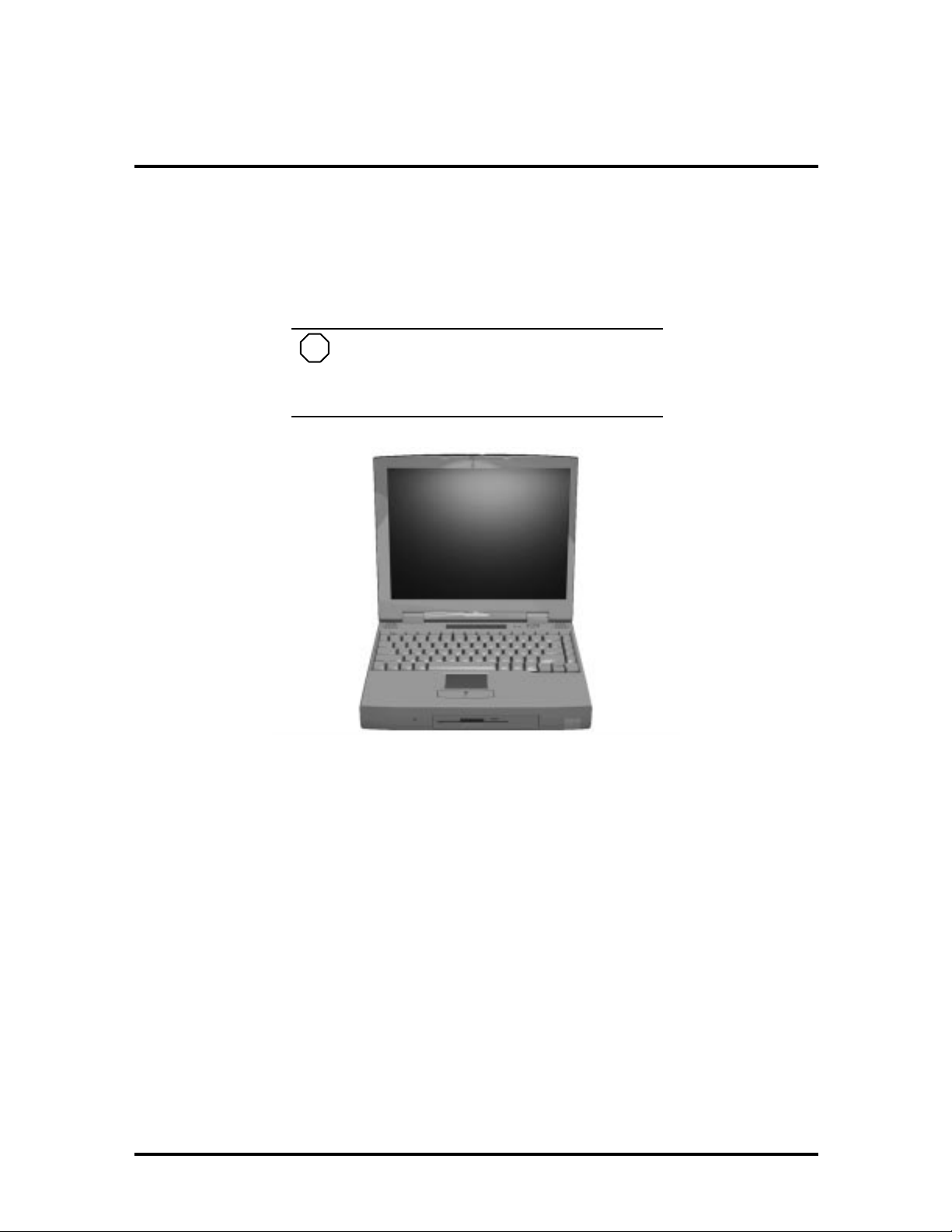
The NEC Versa 6200MX noteboo k computer is lightweight, compact, and fully IBM compat ible. T he lates t addition to the NEC Versa family in clu des the NEC Versa 6200MX.
NOTE
This service manual covers only the NEC
Versa 6200MX model. All figures in this manual
reflect this model.
Figure 1-1 NEC Versa 6200MX Notebook
This section of the manual provides system configuration information, including an overview of hardware and interface components. See the following table for a systems specific
brea kdo wn of hardware.
Page 14

1-2 Technical Information
Table 1-1 Model Configurations
FEATURE NEC Versa 6200M X
CPU Intel Pentium® with
On-Boar d DRA M 32-MB
Video M emory 2-MB
Hard Disk Driv e 2.1 GB
CD-ROM Reader 10X CD ROM Reader
Color LCD 13.3” Extended
HARDWARE OVERVIEW—FRONT
MMX technology
P55CLM/166 MHz
Graphics Array
(XGA),TFT Color
Display
Take a moment to be come familiar w ith th e locatio n and fu nction of co nt rols located on th e
front of the system.
Liquid Crystal Display (LCD)
The LCD operates with the Chips & Technologies 65550 VGA controller. The contro ller
supports XGA, uses a 64-bit accelerator with a Peripheral Component Interconnect (PCI)
interface. The LCD also supports VESA timing.
The NEC Versa 6200MX LCD features the following:
13.3-inch Extended Graphics Array (XGA) TFT high resolution active matrix
XGA c olor display
0.264 mm dot pitch
18-bit digital interface
1024 x 768 resolution
256,000 colors.
Additional LCD panel features:
Power LED that indicates the current power status. This LED is visible with the
LCD panel opened or closed.
Slide switch that adjusts screen brightness.
Page 15
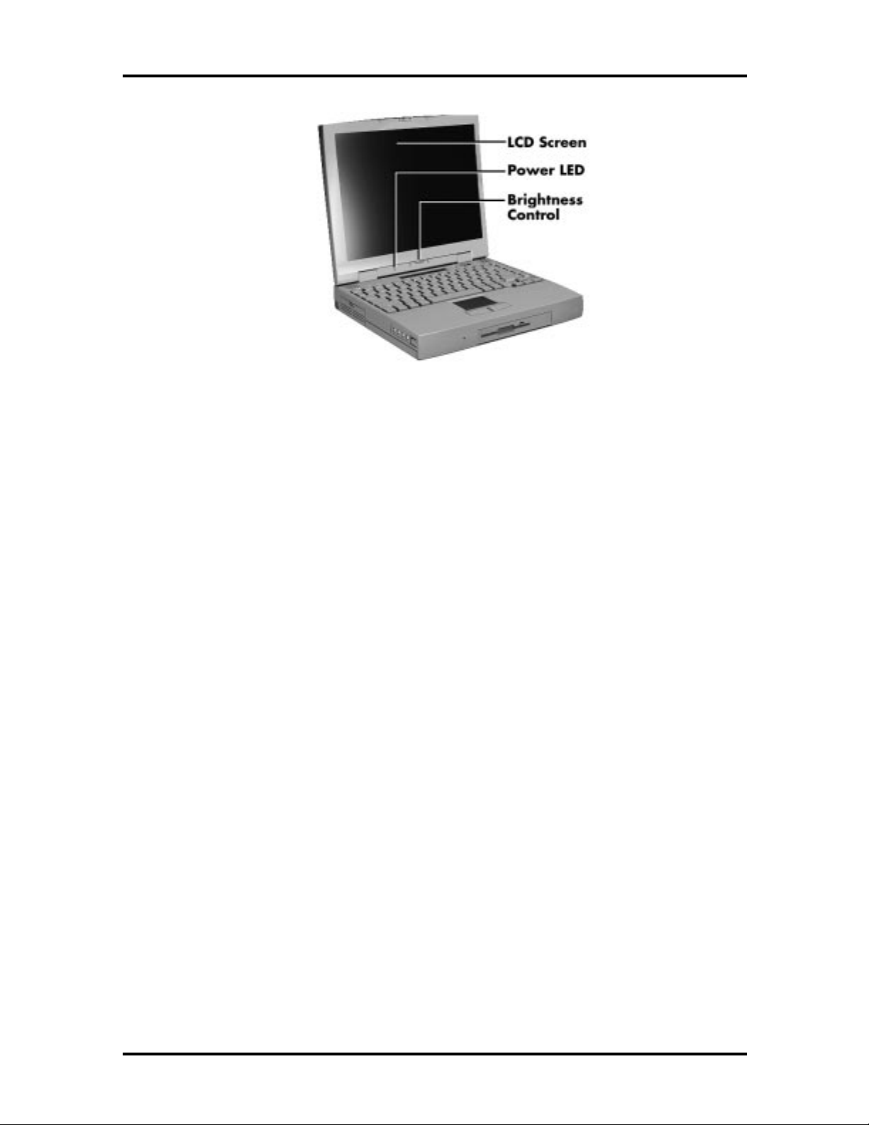
Technical Information 1-3
Figure 1-2 LCD Panel
Another video feature includes a CRT port o n t he system's rear panel that allows the user to
connect an opt ional monochrome or color external display to the system. The computer can
support the LCD and external display simultaneously.
Power- sav ing features for con trolling t he L CD's backlig ht ing in clude th e ROM-based h ot
key combination Fn F5, and Auto Setup power management set tings. See Section 2, Setup
and Operation, for information on using these settings. In addition, the automatic LCD
status featur e conserves the backlight. When the LCD is closed the backlight shuts off
automatically, saving battery power.
Power Button
Slide the power butt on to t he right to power on and power off the computer. The power
butto n is a “smart” switch, meaning that it recognizes when the system is in Suspend mode.
If in Suspend mode, you cannot power off until you press the suspend butto n again to bring
the system out of Suspend mode.
Page 16
1-4 Technical Information
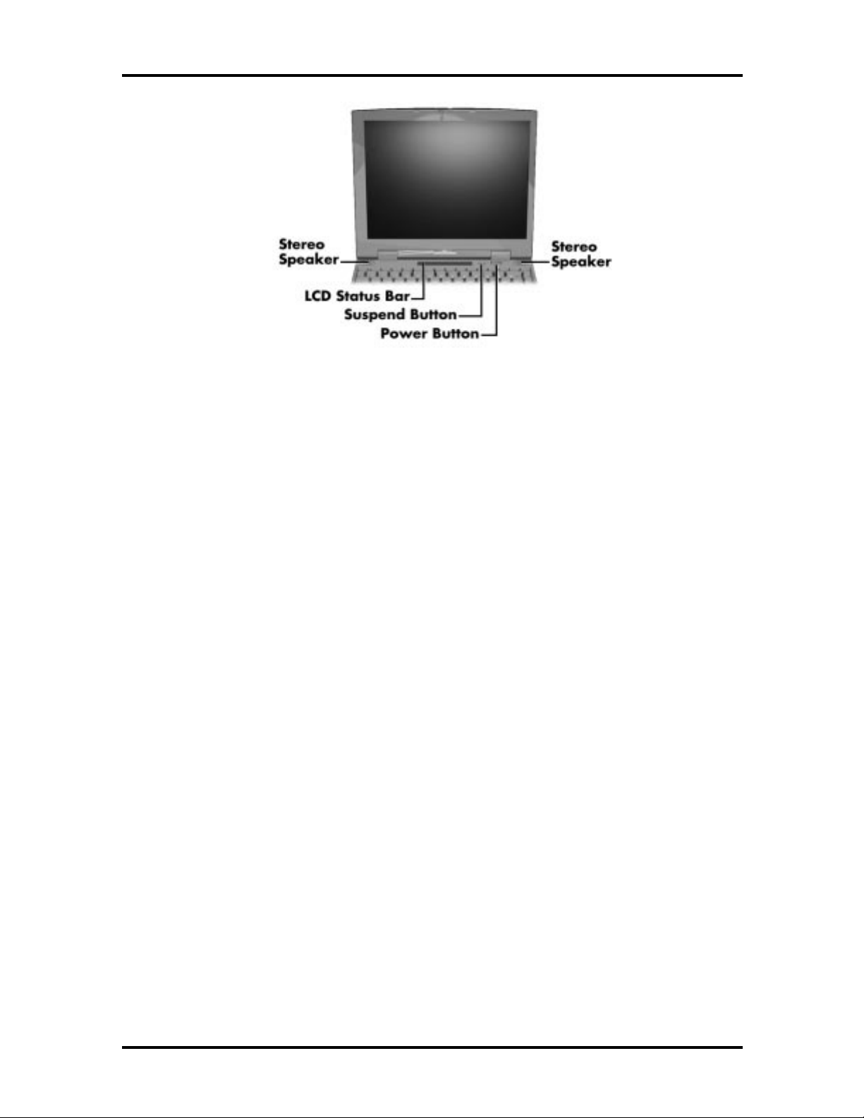
Figure 1-3 Power Button Location
LCD Status Bar and Power Indicator
The LCD status bar is situated right below the LCD screen. It pro vides an easy way to detect system stat us. Different graphic icons appear on the LCD bar indicating that a device is
accessed, an operat ion performed, or a po wer mode activated. The graphic icons displayed
on the LCD bar resemble either their physical characteristics or their primar y function. See
the LCD Stat us Bar figure shown next, and the descriptions that follow for the specific
meaning of each icon.
The power indicator is located just above and to t he left of the status bar. T he power indicator lights green when computer power is on.
Page 17
Technical Information 1-5
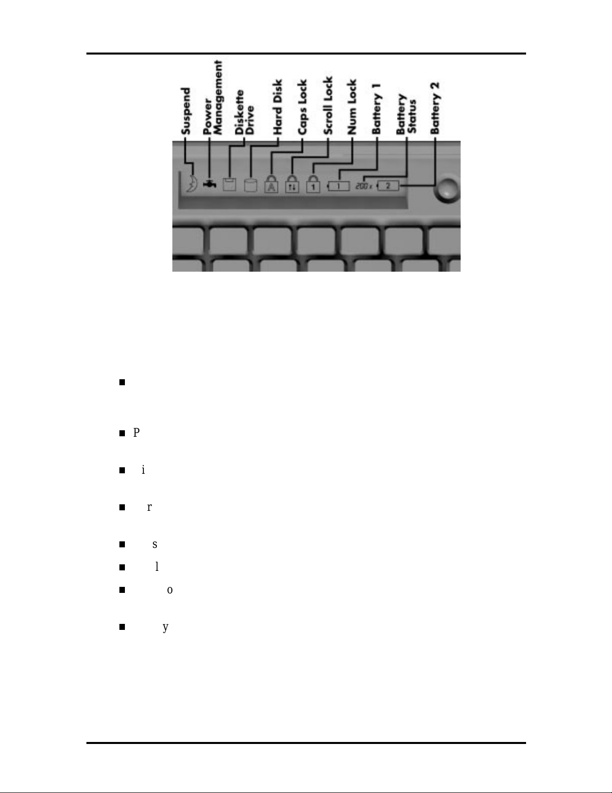
Figure 1-4 System Status Bar
Status Icons
The following list defines the status icons displayed in the system status bar.
Suspend — appears when the system is in Suspend mode. Suspend mode conserves system power by shutting down devices in the system while retaining data
and system status.
Power Management — shows the current power management mode in use, including Off, Custom, High Performance or Longest Life.
Diskette Drive — appears when the NEC Versa writes data to or retrieves data
from a diskette.
Hard Disk — shows when the NEC Versa writes data t o or retrieves data from
the hard disk.
Caps Lock — appears when Caps Lock is in effect.
Scroll Lo ck — sh ows th at Scr oll Lo ck is in e ffect.
Num Lock — appears when Num Lo ck is in effect. Num Lock lets the user enter
numbers for calculations via the numer ic keypad.
Battery Stat us — displays the percentage of battery power available.
Battery 1 appears when you have the main battery installed in the battery bay.
Batter y 2 appears when you have an optional battery installed in the
VersaBay II.
Page 18
1-6 Technical Information
Keyboard
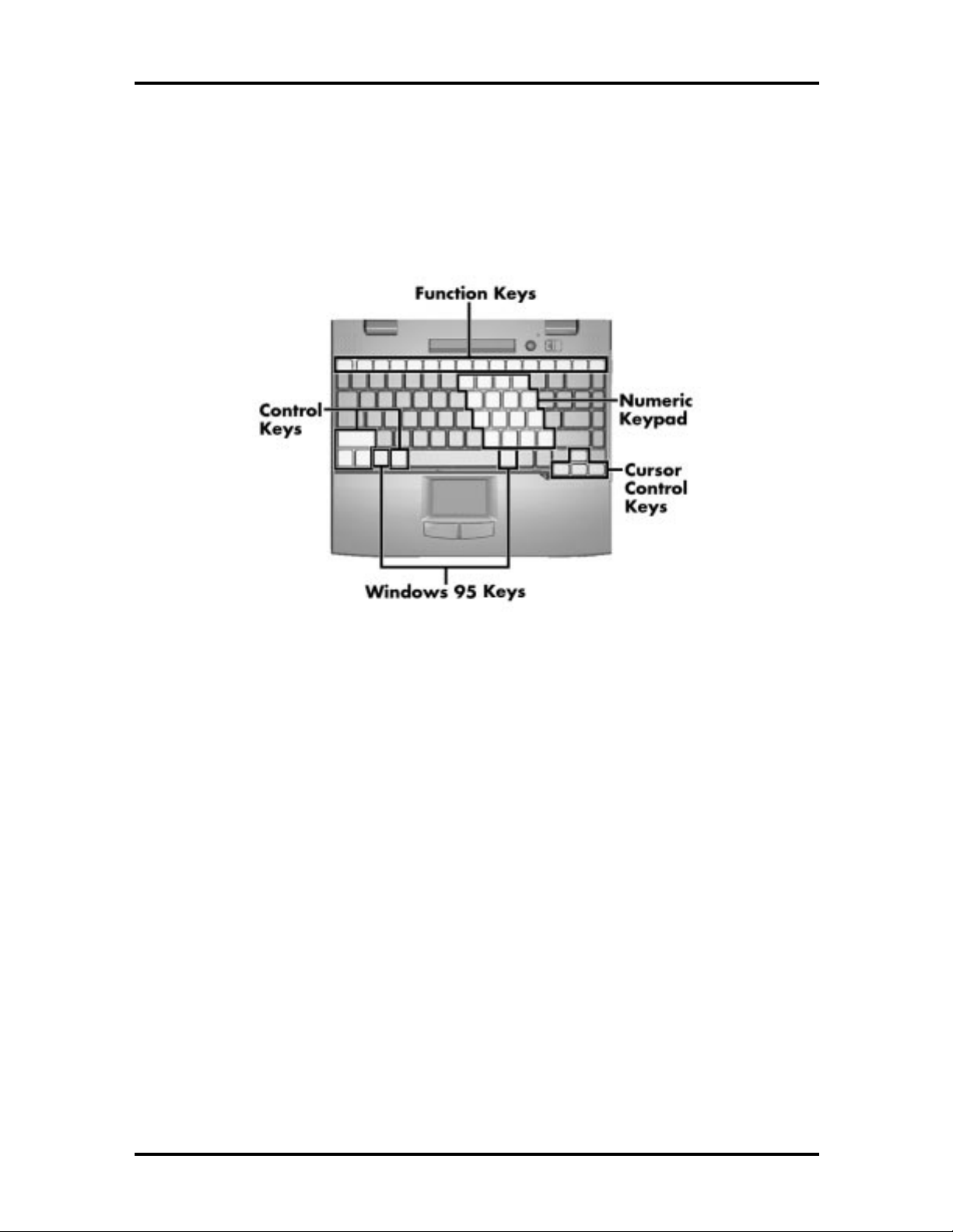
The built-in, 85-key keyboard (U.S.) or 79-key keyboard (UK and Germany) uses t he standard QWERTY format. The keyboard pro vides 12 function keys and 7 cursor contr ol keys,
with an Fn key for ROM-based key functions. The numeric keypad is embedded in the standard key layout.
Figure 1-5 Keyboard La yout
NEC VersaGlide
The NEC VersaGlide is a built-in mechanism that functions as the system’s mouse. It contro ls the on-screen po inter (cur sor). T o use the VersaGlide, move your finger across t he
NEC VersaGlide pad, and the cursor follo ws. The butto ns below the NEC VersaGlide allow the user to select or deselect menu items. Tap and double-tap are supported o n t he
VersaGlide pad.
The PS/2 Microsoft mouse is the system’s default pointing device unt il the user selects the
NEC Setup icon. When the user selects the NEC Setup icon, the NEC VersaGlide is
installed as the system pointing device. If an external mouse is installed, the NEC
VersaGlide is deactivated. A serial mouse is not supported.
Page 19
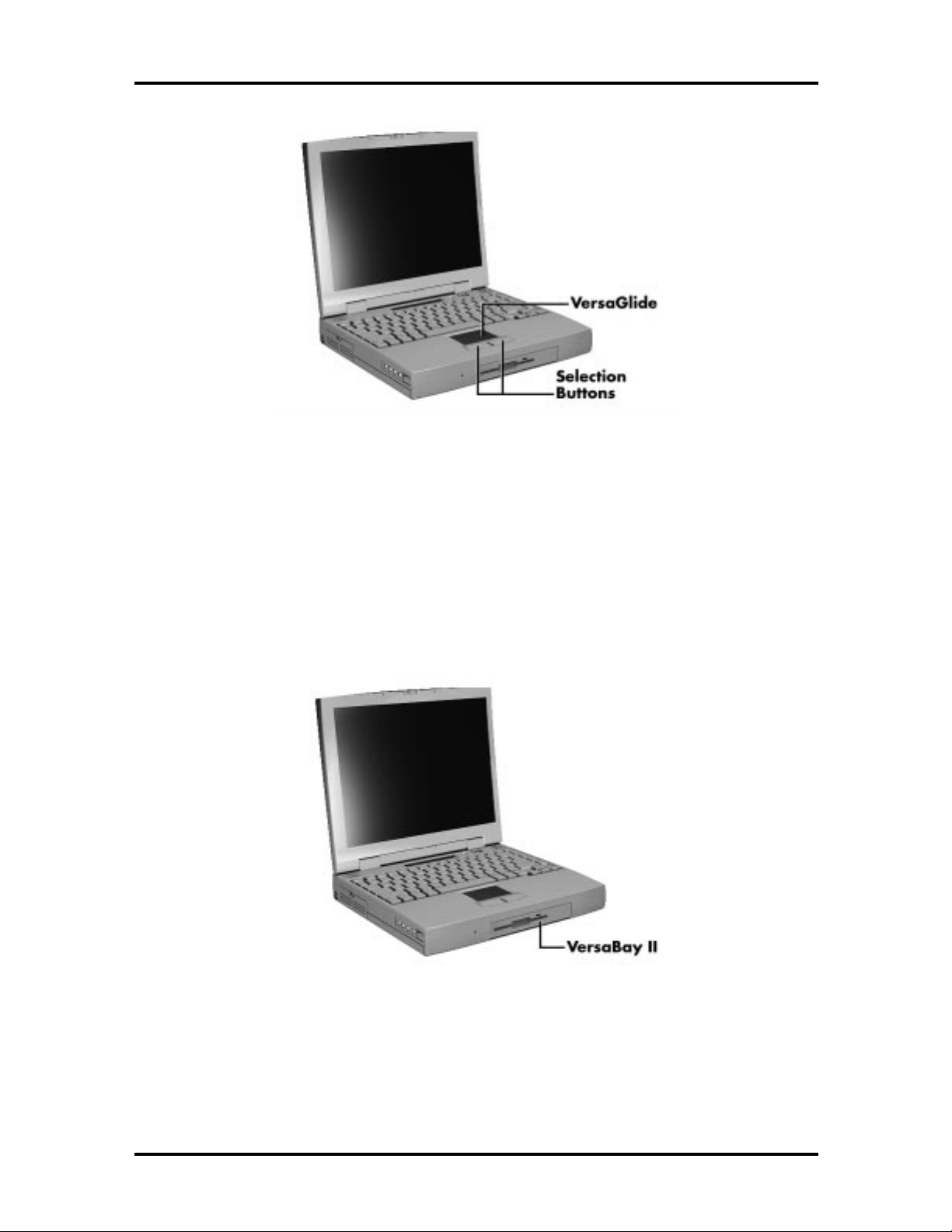
Figure 1-6 VersaGlide Location
Technical Information 1-7
Diskette Drive and the NEC VersaBay II
A standard 1.44-MB diskette dr ive comes installed in t he VersaBay II slot on the front of
the computer. T he VersaBay II expansion slot lets the user r eplace the standard diskette
drive with the 10X CD-ROM reader t hat also ships with the system. In addition to the
CD-ROM reader, the VersaBay II accepts NEC options including a seco nd battery pack, or
an additional hard disk.
Figure 1-7 NEC VersaBay II Location
Page 20
1-8 Technical Information
Infrared (IR) Assembly
The IR assembly consists of a small board with two infr ar ed LE Ds, connected to the Graph
board at co nnector P10. The board allows the NEC Versa computer to communicate with
other infrared-ready computers. For example, the infrared port allows the user to transfer
files between the NEC Versa and an IR-equipped computer, or pr int to an IR-equipped
printer without using cables.
NOTE
Do not use the IR port directly under fluorescent incandescent light.
HARDWARE OVERVIEW—RIGHT SIDE
Review the following section for a description of the hardware on the right side of the NEC
Versa.
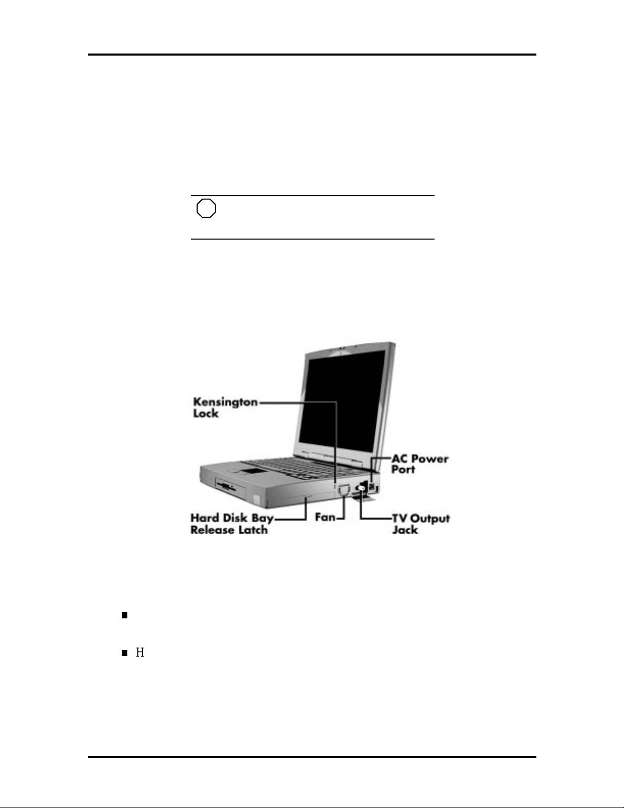
Figure 1-8 Right Side Fe atures
Kensingt on Lock — Gives the user the option to add an op tional Kensingt on
Lock.
Hard Disk Drive Bay Cover Release Latch — The hard disk drive bay contains
the removable hard disk drive. The system ships 2.1-GB hard disk drive.
To access t he hard disk drive, simply turn the system over and lift up the hard disk
drive bay co ver r elease latch while pushing t he cover away from the system.
Page 21
Technical Information 1-9
Fan Vents — Allow your system to co ol properly and maintain a safe operating
temperature.
!
Always keep t he fan vents clear to allow proper
CA UT ION
system cooling.
TV Out Jack — Lets you use your television set as an external monitor. This port
supports both NTSC and PAL signals.
NOTE
The TV Out port does not suppo r t the
SECAM signal used in some countries. For
proper display, set the video mode to 640 x 480.
AC Power Por t — Use the power jack to attach the NEC Versa to a DC power
source, such as t he AC adapter or the op tional DC car adapter.
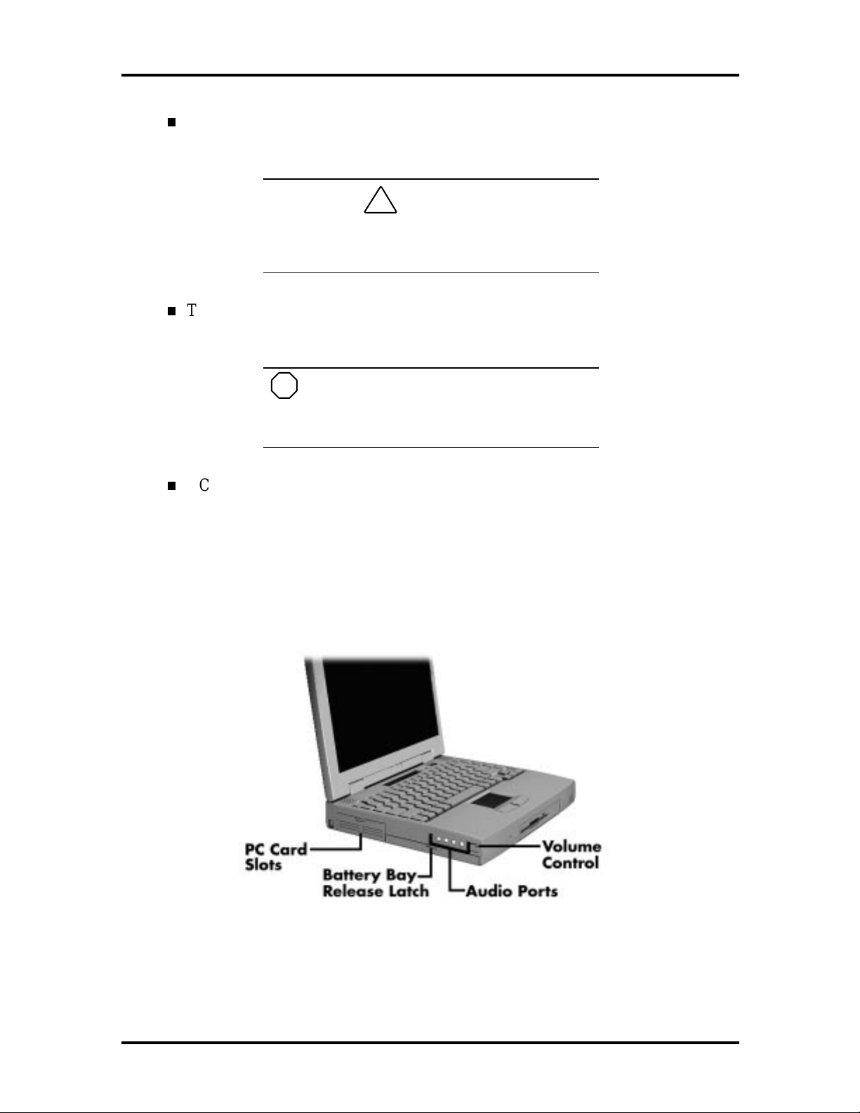
HARDWARE OVERVIEW—LEFT SIDE
Review the following section for a description of the hardware on the left side of the NEC
Versa.
Figure 1-9 Left Side Features
Page 22

1-10 Technical Information
PC Card Slots
The PC card slot compartment houses two Type II devices, or one Type III device. For
Type III cards, insert the PC card into t he lower slot. Insert the card with the pin sockets
facing towards t he drive and the label facing up. To r emove the PC card, push on t he eject
butto n t o release the pin connections and slowly pull out t he card.
The NEC Versa also comes with DOS/Windows PC card drivers for supporting various PC
cards like modem and network cards.
Battery Compartment
The battery compartment houses the rechargeable Lithiu m Ion (Li-Ion) battery pack. The
battery pack instantly charges whenever you connect the AC adapter t o the notebo ok. It is
very important to always have the battery installed in the notebook to insure that it is continuously charged. If the battery pack is uninstalled for a long period of time, the battery
cells are drained, causing battery pack to deter iorate.
The ba ttery bay cont a ins a n eight-cell Lithium Ion (L i- Ion) batte ry that lets you run your
system on DC power.
Audio Ports and Volume Control
Audio ports let you plug in external audio devices and the volume controls gives you contro l over speaker volume.
Volume Co nt rol — Allo ws you to control the speaker vo lume .
Headphones — Let you connect external headphones or speakers to your NEC
Versa 6200MX. Plugging in headphones disables the built-in system speakers.
Line-Out — Lets t he NEC Versa 6200MX act as an input source for another
audio system. Connect this port to a Line-In port on another audio system to play
or record.
Line-In — Lets you use another audio system, like a home stereo, as an input
source. Use a cable to connect to the Line-Out po r t on the other audio system to
record or play.
Microphone (MIC) — Allows you to connect an external micropho ne for monophonic recording or amplification through the unit. Plugging in an external microphone disables the built-in micr ophone.
Page 23
Technical Information 1-11
HARDWARE OVERVIEW—REAR SIDE
Review the following section for a description of the hardware on the rear of the NEC
Versa.
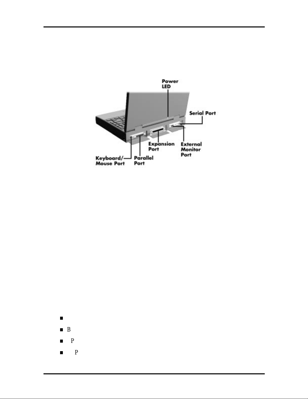
Figure 1-10 Rear Features
Keyboard/Mouse Port
Use the standard PS/ 2 port to connect an external PS/2-st yle mouse or a PS/2-st yle keyboard to the system. With an optional Y-cable adapter, you can connect both a mouse and a
keyboard at the same time. A serial mouse is not supported.
Parallel Port (LPT1)
The 25-pin print er port provides a parallel interface to which you can connect a parallel
printer or pocket net work adapter. Use this port to connect a parallel printer or ot her
parallel device. The port is IEEE 1284 compat ible. It supports bi-directional (AT) mode,
En han ced C apabilities Port (ECP) mode, Enhanced Parallel Port ( EPP) mod e, (365SLcomp atible), nibble mode, a nd b yte mode ( PS/2) .
Th e p ar allel por t default is Ext ended Capabilitie s Port ( EC P) mo de . U se Se tup to change
the default to one of the following.
Uni-directional
Bi-directional
EPP
ECP
Page 24

1-12 Technical Information
Expansion Port
This port provides a connection for NEC Versa options including the NEC PortBar 6000,
NEC Versa Docking Station 6000 Plus and the NEC Floppy Disk Drive (FFD) Connector.
External Monitor (Video) Port
Use this 15-pin port to attach an external monitor to your NEC Versa. You can run the
LCD display and the external monitor simultaneously o r run either alone.
Serial Port (COM1)
The 9-pin serial port provides a serial interface to which you can connect an RS-232C
device such as an external serial pr inter or modem. A serial mouse is not supported.
HARDWARE OVERVIEW—INTERNAL COMPONENTS
Review the following sections for a description of the system’s internal hardware.
Battery Pack
The system uses a rechargeable lithium-ion (Li-Ion) battery as its transient power source.
The battery pack installs in the compartment next to the VersaBay II on the bottom of the
NEC Versa. The battery stor es 14.4 vo lts with a 2600 mAh capacity.
The battery pack powers the NEC Versa for appro ximately 2 to 4 hours. In addition, the
user detect s how much battery power is available via the percentage displayed o n t he st atus
bar or accessing the Power Gauge utility.
When battery power is getting low, connect the AC adapter t o a wall outlet and recharge
the battery. It takes approximately 2 hours to recharge the battery whether or not the syst em is in use.
When battery power is very low, the power LED flashes amber.
Hard Disk Drive
A standard 2.5-inch 2.1-GB hard disk drive ships with the system. The 2.1-GB hard disk
drive specifications are list ed next.
Toshiba IBM
Track-to-track seek r ate 3 ms 4 ms
Average seek time 13 ms 13 ms (read), 14 ms (write)
Revolutions per minute 4200 4000
Data transfer rate 16.6 MB/sec 16.6 MB/sec
Internal data rates 38.6∼69.8 Μbit/sec 39.1~61.6 Mbit/sec
Page 25
Technical Information 1-13
Increase the system hard disk space by installing another h ard disk drive in the V er saBay II
slot in the front o f the computer using the opt ional hard disk drive adapt er kit.
Diskette Drive
The interchangeable 3.5-inch 1.44 MB diskette drive installs in the front of the system in the
VersaBay II slot.
10X CD-ROM Reader
A 10X CD-ROM reader ships with the NEC Versa 6200MX. The interchangeable tenspeed CD-ROM reader features t he latest in CD-ROM technology. It installs in the front of
the system in the VersaBay II slot. The CD-ROM reader is assigned to the next available
drive letter. T he CD-ROM reader operates at different speeds depending on whether the
CD in use contains data or music. This improves video and sound quality.
CPU Board
The CPU board (G8YAL) is a rectangular-shaped board located between the main board
and I/O board. The CPU boar d is part of a subassembly, which includes a heat sink, fan and
the CPU board.
The NEC Versa 6200MX models ship with Intel’s P55CLM/166 MMX installed on the
CPU board. The boar d uses the industry standard PCI interface, with a 66 MHz bus speed.
Figure 1-11 CPU Board Layout
Page 26
1-14 Technical Information
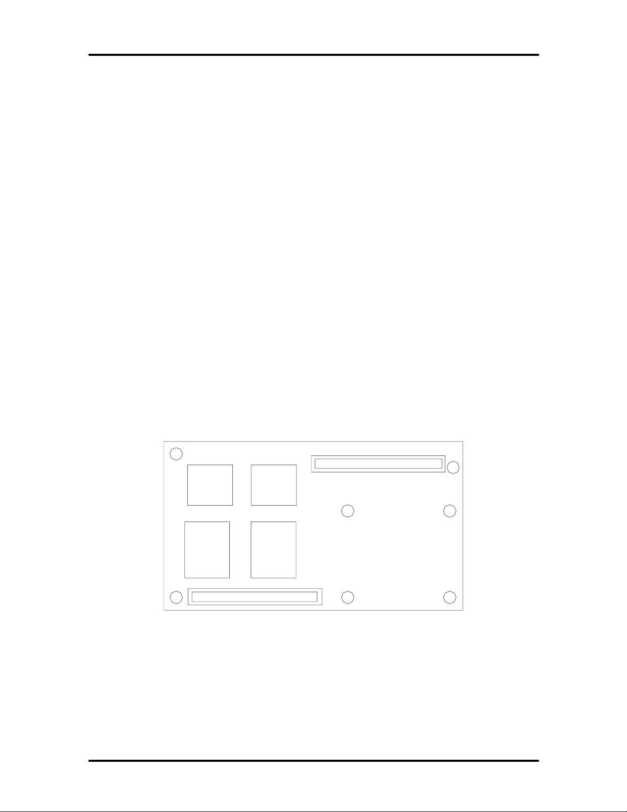
Sound Board
Th e sound board (G8 YAQ) provid es th e NEC Versa system with its aud io capabilit ies via
line-in/line-out jacks, and headphone/micr ophone jacks. It is situated on top of the main
board. The sound board integrates the following features:
ESS Technology Plug and Play suppo r t
ES1878
Integrat ed Music Synthesis, ESFM™ and Stereo Digital to Analog Converter
(DAC) FM Synthesizer
16 bit Stereo CODEC
4.0KHz to 44.1KHz Sampling Rate
7 Channe l Mixer.
3D Audio Effects Chip
ES938 Spatializer ® 3D Stereo So und
Figure 1-12 Sound Board La yout
Page 27
Technical Information 1-15
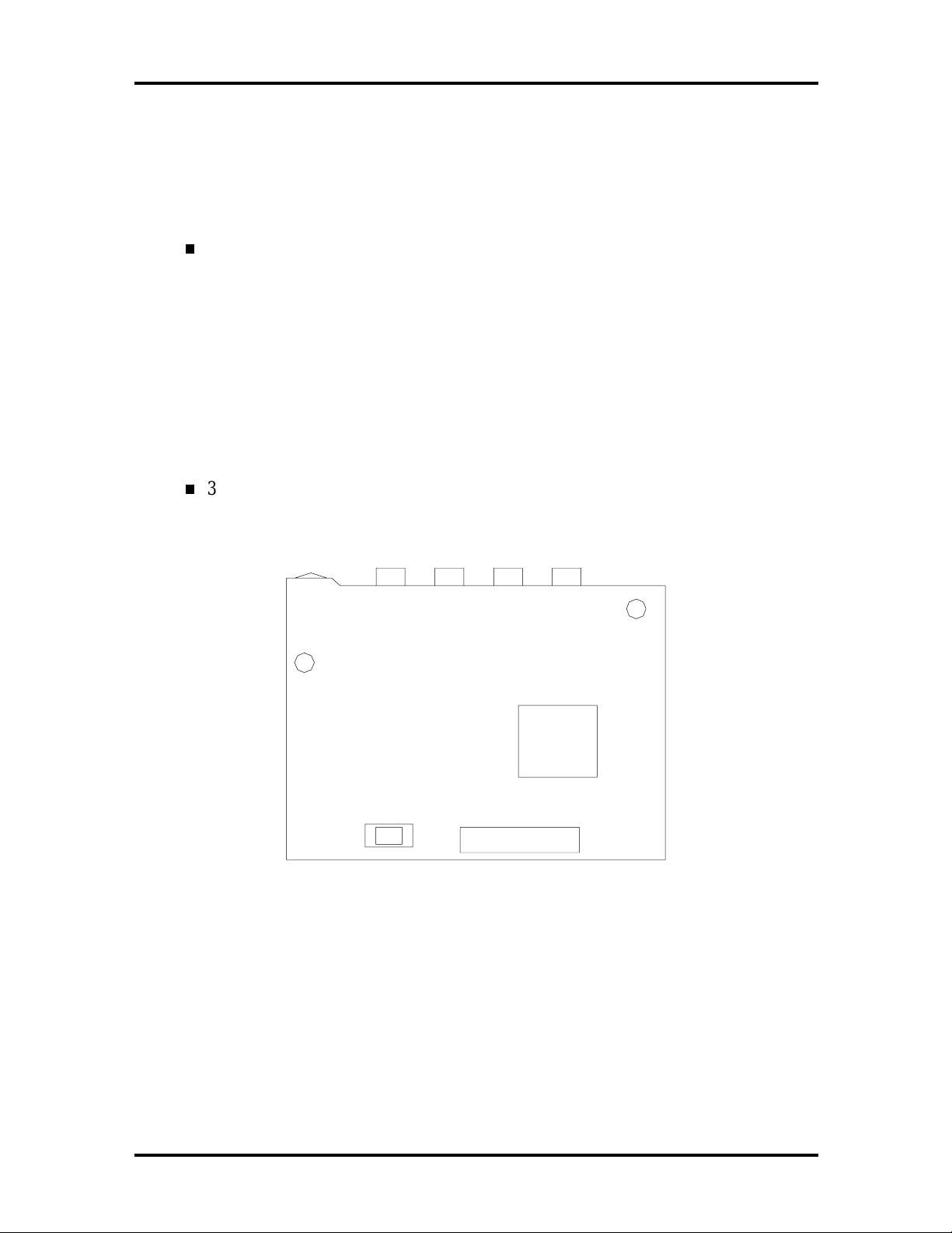
Graph Board
The system Graph board (G8YAN) houses a variety of connectors and cont r ols, including
the DIMM connecto r s. These are identified in t he diagram shown in Appendix A.
Figure 1-13 Graph Boa r d Layout
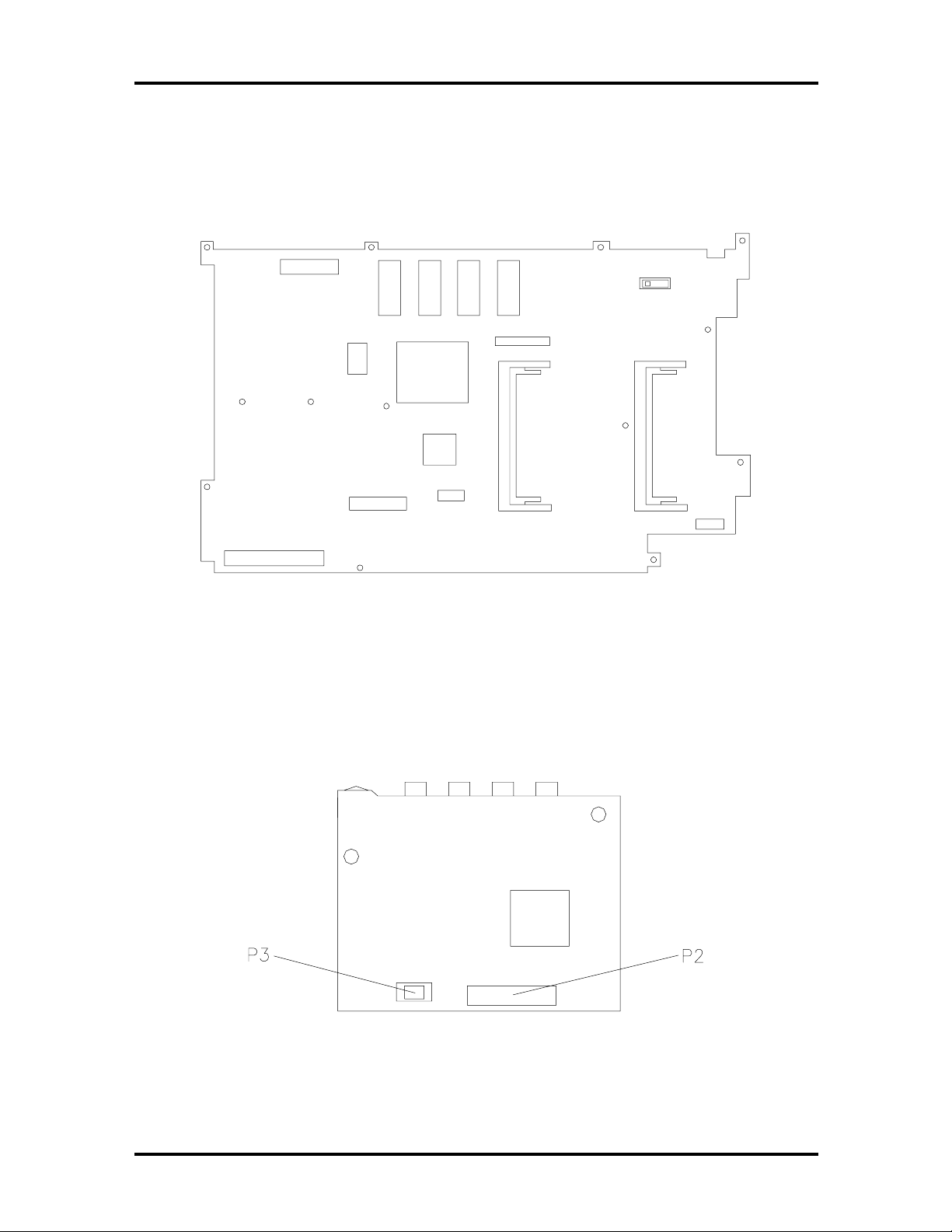
I/O Board
The system I/O board (G8YAP) contains peripheral subsystems including serial, parallel and
video ports, and charger. It is located underneath the main board. Refer to Appendix A for
a list of connecto r s.
Figure 1-14 I/O Board Layout
Page 28

1-16 Technical Information
CMOS Battery
The lithium battery (3 Volts, 280 mAh capacity) is attached to P13 o n t he Graph board. It
provides battery backup and prevents data loss in the syst em’s complement ary metal oxide
semiconductor (CMOS) RAM. This memory area contains information on the system’s
configu ra tion like date, t ime, drives, and memory. The CM OS batter y lasts approximately
three years.
Bridge Battery
The bridge batter y saves the memory contents and system status for up t o 5 minutes while
in Suspend mode. It is connected to the Graph board via connector P 11. T he AC adapter
maintains voltage in the bridge battery when the system is powered on or off. The bridge
battery stores 7.2 Vo lts, 70 mAH.
SYSTEM MEMORY
The Graph board provides 32 MB (3.3 V SO-D I MM) of standard RAM.
Optional SO-DIMMs with a value of 16-, 32-, or 64-MB can be added to increase system
memory up to a maximum of 128-MB (70 ns 3.3V EDO access). In addition, 256-KB of
read-only memory (ROM), 1 x 28F020, enables the system BIOS to be flashed.
The system provides 2 MB of video RAM (50-ns HyperPage mode, self-refresh).
The following Cache RAM is provided:
L1: 16 KB (Internal Pentium)
L2: 256 KB write back (External).
Memory Map
The system supports system and video shadowing, both controlled through complementary
metal oxid e semiconductor (CMOS). T he system supports BIOS as a cacheable area with
write pr otection. Table 1-2 lis ts t he syste m's memo ry ma p.
Page 29

Technical Information 1-17
Table 1-2 Memory Map
MEMORY SPACE SIZE FUNCTION
000000-0002FFh 768 bytes BIOS Interrupt Vector Table
000300-0003FFh 256 bytes BIOS Stack Area
000400-0004FFh 256 bytes BIOS Data Area
000500-09FFFFh 640 KB Applic ations Memory ( used by t he OS, device
drivers, TSRs, and al l DOS applications)
0A0000-0AFFFFh 64 KB Video Buffer ( E GA and VGA)
0B0000-0B7FFFh 32 KB Video buff er ( monochrome, CGA color, VGA
monochrome)
0B8000-0BFFFFh 32 KB Video Buffer (CGA, EGA color, and VGA c olor)
0C0000-0CBFFFh 48 KB Video ROM (EGA and VGA)
0CC000-0CFFFFh 16 KB Unused, (Reserv ed for Adapter ROMs and other
devices requiring ROMs)
0D0000-0DFFFFh 64 K B Used by Adapter ROMs (i. e., network controllers,
hard disk controllers, SCSI host adapters)
0E0000-0EFFFFh 64 KB Used by System ROM adapters (i.e., network
controllers with boot capability)
0F0000h-0FFFFFh 64 KB System AMIBIOS (incl udes Set up and har d disk
drive utilities)
100000h-1FFFFFF 32 MB Built-in Ex tended Memory
2000000-5FFFFFF 64 MB Extended M emory
SYSTEM VIDEO
The system's LCD operates using the Chips and Technologies 65550 VGA Controller.
Video signals travel fr om the contro ller through the system's 15-pin D-SUB connector using 5 volts.
System video integrates a PCI- bus interface. The system ship s with 2 MB Video RAM
(VRAM). It supports video modes up to 1024 x 768 with 64K colors in LCD mode.
See A pp endix B for a list of Video modes .
Page 30
1-18 Technical Information
PARALLEL INTERFACE
The system' s parallel interface integrates National Semiconductor’s PC87338 chip with a
25-pin D-subconnector. The port is located on the system's rear panel.
The modes of operation available for a PC87338 chip are:
comp atibility mod e
nibble mode
byte mo de
Ex tended Capabilities Port (ECP)
Enhanced Parallel Port (EPP).
The user selects between four parallel interface modes using Auto Setup. These include
un idir ec tional, bid ire ctiona l, extended or e nhanced. Unid ire ctiona l mode sends data out put
from the standard ISA port only. Bidirectional mode sends data using the standard ISA port
or PS/ 2 technology. Enhanced mode enables high speed data transmission to occur using
either th e u nidire ctional or bidir ec tional modes.
The default parallel port address is 378h and the interrupt level is IRQ07. Pin locations for
the parallel interface are listed in Appendix A.
SERIAL INTERFACE
The RS-232C serial port is a 9-pin connector on the system’s rear panel. The serial port
consists of a 16550A and 16450 compatible serial port controller with a programmable
baud rate up to 115,200 bps. The serial po r t connects an RS-232C device or an external
modem. The default serial port address is 3F8h and the int err upt level is IRQ04.
NEC VERSA CHIP SET
Refer to Table 1-3 for a quick summary of chip types used in the system. See the Abbreviations section at the beginning o f this manual for a t r anslation of chip technologies.
Page 31

Technical Information 1-19
Table 1-3 NEC Versa Series Chip Types and Technologies
CHIP MANUFACTURER DESCRIPTION TECHNOLOGY
Intel Pentium P55CLM Intel 166 MHz CPU 320-pin TCP
82437MX (MTSC) Intel M-Triton Sy stem Controller 208-pin S QFP
82438MX (MTDP) Intel M-Triton Dat a P ath Controll er 100-pin TQFP
82371MX (MPIIX) Intel M-PCI IDE ISA Xcelerator 176-pin TQFP
N28F020-150 Intel 256k x 8 F lash ROM 32-pin PLCC
C&T 65550 Chips & Technologies VGA Controller 208-pin FQFP
PC87338 National
Semiconductor
M38813E Mitsubishi Keyboard Controller 64-pin TQFP
PC1131 Texas Instruments PC Car d Controller 208-pi n QFP
ES1878 ESS Technologies Sound Controller 100-pin PQFP
ES938 ESS Technologies 3D Sound Controller 28- pin SSOP
Diskette Controller, IDE,
Parallel Interface
100-pin TQFP
Intel Pentium P55CLM Microprocessor
The 166 MHz Intel Pentium microprocessor with MMX technology used in the NEC Versa
se ries c ompu ter is built on Intel’s adva nced 2.5V BiCMOS silicon technology. The CP U
has on-ch ip d ua l-p roc essing, a local mu ltipr ocessor inte rrupt con troller, and power management features. NE C adopted t he chip specifically for its pipelined Floating Point Unit
(FPU) , and local in ter rupt mana gement.
M-Triton System Controllers
NEC implements Intel’s Mobile Triton technology (MTDP 82430MX and MTSC
83437MX) for several of the notebook’s subsystems including the DRAM controller, Second Level Cache Contro ller and PCI Bus interface. The Mobile Triton PCI set features include:
3.3V EDO DIMM (70-ns) support
direct mapped organization write-back policy
fully synchronous 33 MHz PCI bus interface.
Page 32

1-20 Technical Information
256K X Flash ROM
The N28F020 flash ROM is a 32-pin, plastic lead chip carrier (PLCC). The chip allows easy
updates to the system's BIOS if needed. More specifically, the ROM is flashed electronically, insta lling th e latest BIOS re visions to the syste m. It is po ssible to reprogram the BIO S
up to 100,000 times. See Section 2, Setup and Operation, for BIOS update procedur es.
The N28F020 provides the syst em upgrade capability as well as the following :
256 KB memory
Quick- Pulse Progra mmin g Algorithm
150 nanoseconds (ns) maximum access time
ET OX Nonvolatile flash te chnolo gy
CMOS low power consumption
ROM BIOS
The system uses a Flash ROM known as t he system's ROM BIOS to store machine language programs. The BIOS size is 256 KB, consisting of the system utility (for PC cards,
Auto Setup), system BIOS, video BIOS, and power management.
The BIOS programs execute the power-on self-test (POS T), initialize CP U controllers, and
interact with the LCD indicator panel, diskette drive, hard drive, communication devices
and peripherals. The system BIOS also contains Auto Set up and provides VGA controller
support. T he ROM BIOS is copied into RAM (shadowing) for optimum performance.
The ROM BIOS cont ains both the system and video BIOS. T he system BIOS is located in
the upper portion of the device; video BIOS is located in the lower portion. System BIOS is
located between F0000h-FFFFFh.
The BIOS often changes after the product release to pro vide enhanced features or bug
fixes. To acquire the latest BIOS r elease, t he ROM is flashed electro nically allowing the
BIOS update to occur without removing the ROM. See Section 2, Setup and Operation, for
BIOS upgrade procedures.
VGA Controller
The Chips and Technologies 65550 is a PCI 64-bit Graphics Accelerator. The integrated
programmable linear addr ess feature accelerat es the graphics user interface (GUI) performance. The controller also supports Hardware Multimedia and VES A interface standards.
The contro ller provides advanced power management that helps to minimize power usage in
t he following modes:
normal operation
Standby (sleep) mode
panel off pow er sa ving modes.
Page 33

Technical Information 1-21
Parallel Interface
The PC87338VJG chip is a 100-pin Thin Quad Flat Plastic (TQFP) chip. The controller
changes 8-bit parallel data into serial data and writes the data to the diskette. Conversely,
the serial data is transmitted from the diskette into parallel data, where it remains until the
read operation takes place.
Additional PC87338VJG chip operations include:
ISA co mpa tib ility
low-power CMOS with enhanced power-do wn mode
Keyboard Controller
The keyboard controller (M38813E) support s a PS/2-st yle keyboard, mouse and password
security feature. Refer to Appendix A for keyboard interface connector pin assignments.
When data is written to the output buffer, the controller generates an interrupt, and requests
the CPU to receive the data. The contr oller auto matically adds an even parity bit to the data
sent and waits for a response. The device must acknowledge that t he dat a was successfully
received by sending a response to the contr oller for each byte of data received.
PC CardBus Controller
The Texas Instruments PC1131 controller interfaces with the PCI bus, PC CardBus socket
and configur ation registers to provide:
compliant with PCI 2.1 and 1995 PC card standards
CardBus slots w ith hot insertion and removal
independent Read and Write buffers for each direction
burst transfers to maximize data throughput on the PCI CardBus bus.
Sound Integrated Circuit
The ESS Technologies chip set (ES1878 Audio Drive and ES938) provides dynamic audio
circuitry with the following:
Audio digital processor
Plug and Play suppo r t
High-performance 16-bit Ster eo Codec
Full- duplex operat ion for simultaneous record and playback
Analog joystick quad timer and digit al joystick support.
Page 34

1-22 Technical Information
Interrupt Controllers
Using interrupts, it is possible to change the system’s code sequence. To change the sequence, reassign the interrupt- levels. Fifteen interrupt s can be used with a cascade connection of two 82C59 interrupt controllers.
Interrupt- level assignments 0 through 15 are listed in Table 1-4, in order of decreasing
priority.
Table 1-4 Interrupt Controll ers
CONTROLELR
(MASTER/SLAVE) PRIORITY NAME
Master 0 IRQ00 Counter 0/Timer 1
Master 1 IRQ01 Keyboard
Master 2 IRQ02 INT out put from controller 2
Slave 3 IRQ08 Real - time Clock
Slave 4 IRQ09 Infrared Port
Slave 5 IRQ10 Reserved (CardBus controller)
Slave 6 IRQ11 Reserved (CardBus controller)
Slave 7 IRQ12 NEC Ver saGlide Mouse
Slave 8 IRQ13 Mat h Copr oc essor (bui lt into CP U)
Slave 9 IRQ14 Hard Disk Controller 1
Slave 10 IRQ15 Reserved (2nd IDE on Doc k ing Stati on or
Master 11 IRQ03 Not used
Master 12 IRQ04 Serial Port 1
DEVICE
CardBus card)
Master 13 IRQ05 Sound
Master 14 IRQ06 Disket te Drive Controller
Master 15 IRQ07 Parallel Port 1
Page 35

Technical Information 1-23
POWER MANAGEMENT OVERVIEW
Power Management in the NEC Versa lets you conserve energy, save battery power, extend
the life of your LCD backlight , and protect against data loss due t o low battery power.
Set so me features to function automatically or activate them manually with the keyboard or
a butto n. It is wise to keep Power Management features enabled, even when using AC
power.
The system ships with many power-saving features already enabled. See the following table.
Table 1-5 Automatic Power-Saving Features
DEVICE
Video 2 m inutes Video tur ns off after there is no
Hard Disk 2 minute Har d disk motor stops when hard disk is
Standby 4 minute System enters Standby mode after total
DEFAULT
TIMEOUT
COMMENT
keyboard or VersaGl ide input for the
specified timeout.
not accessed for specified t imeout.
system inact iv ity.
You can change the timeout period for any of the devices using Setup. See Section 2 for
Setup u tility pr ocedu res.
Use the
FnF7
key combination to s et the power man ageme n t level. The fa ucet icon chang es
when the power management setting changes. You can toggle between Highest Performance, Longest Battery Life, Custom Power Management, and Off. Default values change
depending on the type of power management you use.
NOTE
Some power management features are not
available when connected to a docking station.
For example, the Suspend and Save to File features do not work. The system enters Standby
mo de if Suspen d or Sa ve to File is activ ated.
Page 36

1-24 Technical Information
System Power Management
NEC Versa system power management consists of the following operation modes. These
modes are:
Active Mode In active mode, the system uses maximum power. I t operates
with the default clock speed. The system continues to run at this speed unless
overwritten by the power management features.
Standby Mode The system switches auto matically to Standby mode. This
eliminates unnecessary power co nsumption when you operate the system on battery power or AC. Standby mode shuts down the LCD panel, providing privacy as
well as power savings.
Suspend Mode Suspend mode causes the CPU power down, local devices to
shut down, and register values to be stored in RAM. System RAM is put into a
slow refresh state. A moon icon in the LCD Status Bar indicates that Suspend
mo de is in e ffec t.
The system resumes Active mode when you press the Suspend but ton, or the
sys tem is set to r esume at a certa in t ime of d ay. Suspen d mode le ts yo u save
power without first saving the working data.
Press the Suspend button to enter S uspend mode when you need to be away fr om
the system for a short period of time and want to retur n t o where you left off.
In addition, to quickly act ivate the Save to File feature, press the Fn and Suspend
button simu ltaneously. This shuts down the system, and saves the current working
data to a file.
Local Power Management
Use Auto Setup to select one of four power management sett ings for local devices. T hese
include Lo ngest
Off. The power management levels ar e also available during AC operation. The NEC Versa
computer ships with Longest
Section 2 for specific procedures on using Auto Setup t o select the power management
settings.
Whe n set to L on ge st Bat ter y Life, CMOS w ill set loc al d evic e timeout va lues, a local standby timeout value, and a suspend timeo u t value to ensure the longest batt er y life. T he Highes t Pe rforman ce settin g selects CMOS values tha t will provide minimal ene rgy sa ving s and
a shorter bat tery life. The custom settings enable end-users to set the timeout values of their
choice. The Pow er Man ag ement Off selection terminates all p ower ma n ag ement timer s.
Battery
Life, Highest Performance, Custom Setup, and Power Management
Battery
Life as the default power management setting. See
Page 37

Technical Information 1-25
Local device timers in t he system contro l power consumption in t he LCD and Hard Disk
Drive. Table 1-6 shows NEC Versa Series Maximum Performance default power management timer s.
Table 1-6 M aximum Performance Default Settings
POWER
MANAGEMENT MODE
Longest Batt er y Life 10 minutes 2 minutes 2 minutes
Highest Per form anc e 30 mi nutes 10 minutes 10 minutes
Custom 10 m inutes 30 seconds 30 seconds
AUTOMATIC
SUSPEND
HARD DISK TIME R
VIDEO TIMEOUT
PLUG AND PLAY
Th e N EC Ve rs a features a Plug and Play functionality. Plug and Play is the a b ility of th e
BIOS and/or operating system to dynamically assign system resources to a newly installed
device without user intervention.
For example, you can suspend the system, add an external keybo ar d , mouse, or monitor,
and when yo u r esume working, the NEC Versa recognizes the devices t hat have been connected to it. Simila rly, you can remove external dev ices in Suspend mode and the N EC
Versa detect s the status when resumed.
NOTE
The system mu st be turned off when
installing t he CD-ROM reader, diskette dr iv e or
hard disk dr ive in th e V er saBay II. Installin g
these devices in Suspend mode may cause
damage to the system.
Page 38

1-26 Technical Information
SPECIFICAT IONS
Table 1-7 provides a complete list of NEC Versa series system specifications.
Table 1-7 Specifications
ITEM SPECIFICATION
Chassis Configuration
Size Width: 11.69 in. ( 297 mm)
Depth: 9.88 in. (251 mm)
Height : 2.3 in. (58.5 m m)
Weight: 7.94 lb (3.61 k g) , Exact weight depends on options
Keyboard PS/ 2 c ompatible, 85-key (bot h U.S. and International) with
QW ERTY-key layout (Internat ional keyboards are countryspecific)
Device Slots Two PC Card slots that support up to two optional car ds-
oriented one on top of the other
One 3 1/2- inch x 0. 75- inch high slot, front ac c ess, for standard
1.44 diskette dr iv e, 10X CD-ROM reader opti onal hard disk
drive or Li-I on battery.
Power 100 to 240 Volts AC at 50 or 60 Hz
Output Voltage — 18.5 V DC, 2.45 A (45. 5 W)
Battery Pack
Front P anel Controls Power Button
LEDs Power LED
Weight .85 lb (.38 K g)
Voltage 14.4 V
Capacity 2600 mAH
Battery Lif e Approxi mately 2 to 4 hours (depending on
model and power m anagement settings)
Rechargi ng Time Approxi mately 2 hour s when the system is
on or off
Bri dge B attery Backs up mem or y c ontents up to 5 minutes
in Suspend mode
Suspend Button
Bri ghtness Control
Batt er y S tatus LEDs
Page 39

Technical Information 1-27
Table 1-7 Specifications
ITEM SPECIFICATION
System Board
CPU Int el Pentium 166 MHz with 16 KB L1 c ac he and built-in
numeric c opr oc essor
Clock S peed 166 MHz
CPU Bus Speed 66 MHz
Fl ash ROM 256 KB: 28F020
Connector S uppor t Parall el —1 port, 25-pin D-sub
Seri al — 1 port, 9- pin D-sub
Infrared — 1 on front of system
VGA — 1 por t, 15-pin high-density D-sub
Ex ternal Keyboard/External Mouse — 1 port, PS/2, 6-pin
MiniDin; exclusionary use or both supported with optional
Y-adapter
Ex pansi on — 1 por t, for optional NEC Dock ing Stati on 6000
Plus, opti onal PortBar 6000, or optional FDD Connector Kit.
Mono MIC IN — 1 port, 3-pin, Mini Pin Jack
Stereo Headphones — 1 port, 3-pin, M ini Pin J ac k , .5 watts per
channel
Stereo Line-In — 1 port , 3-pin, Mini Pin Jac k
Stereo Line-Out — 1 por t, 3-pin, M ini Pin J ac k
TV Out — 1 port; RCA Jack
DC In — 1 port, for A C adapter cable
Memory
System Memory 32 MB high- speed EDO ac c ess, 70 ns
Optional Two DIMM sockets (for base and expansion memory) under
the keyboard, available f or one additional S ODIMM.
Expandable in 16-MB, 32-MB, 64-MB increments
Maximum 128-MB (by swapping base RAM to 64-MB and
adding a 64-MB expansion DI MM)
Video RA M 2-MB
Video I nterface (VGA)
LCD 13.3-inch high resoluti on ac tive matrix thin Film Transistor
(TFT) Extended Graphics Array (XGA) color display, 1024 x
768 pixels, 0.264 mm dot pitc h, 256,000 colors
Page 40

1-28 Technical Information
Table 1-7 Specifications
ITEM SPECIFICATION
Int ernal Device Support
Diskette Drive User-removable 3 1/2-inch, 1.44-MB, installs in VersaBay II
slot
Hard Disk Driv es IDE int er face (built-in), 2 1/2-inch x 1/2-inc h high (thin-height)
System ships with a 2. 1- GB hard disk dri ve
10x CD- ROM Reader User-removable ten-speed (10X) CD-ROM reader, installs in
VersaBay II slot
External Device Support
CRT Display s up to 1280 x 1024 resoluti on x 256 colors
Mouse PS/ 2- c ompatible mouse
Keyboard Bui lt-in 85 k ey k ey boar d with 12 programmable func tion keys,
embedded numer ic keypad and special function control k ey s,
dedicated screen cont r ol keys, and inverted “T” cursor keys /
IBM enhanced 101/102-k ey c ompatible keyboard
Software
Standard Windows® for Workgr oups version 3.11, or Window 95
McAfee VirusScan™
McAfee WebScan™
Of ficial Airline Guide (OAG®)
Netscape Navigator Dial -Up Edi tion
LapLink® Traveling Software
CompuServe®·
Am er ica Online®
MediaMatics Arcade™ MPEG Player
Xing MPEG Player
Recommended Environment
Operation Temperature: 41° to 95°F (5° t o 35° C)
Relat iv e Humidity: 20% to 80% (No condensation)
Storage Temperature: - 4° to 104°F (-20° to 40°C)
Relat iv e Humidity: 20% to 80% (No condensation)
Page 41

Table 1-7 Specifications
ITEM SPECIFICATION
Administrative Compliance
U.S.: F CC, UL
Other Compli anc e PC95 Compliance
Canada: CSA, DOC
Germany: VDE, TUV, CE
Australia: AS for A C adapter only
Energy Star
VESA & PnP VESA
PnP ISA
Technical Information 1-29
Page 42

Section 2
Setup and Operation
This section provides setup and operation information for t he NEC Ver sa series system (includin g cabling, power- on verification and usin g the Se tup utility, from this point on referred to as “Setup” only).
UNPACKING THE SYSTEM
Find an area away from devices that generate strong magnetic fields (electric motors,
transformers, etc.) . Place the shipping carton on a sturdy surface and carefully unpack the
system. The carton content s include the system, CD-ROM reader, AC adapter, AC power
cord, bat tery, software CDs, and user documentation.
HARDWARE SETUP
When connecting power and signal cables, do the following. Note that the power switch
turns on o r off. Slide the switch right to turn it on, slide the switch again to turn it off.
NOTE
Always plug the AC adapter cord into an
easily accessible out let.
1.
Connect the AC adapter cable to the po wer port o n right side of the NEC Versa.
Figure 2-1 Connecting the AC Adapter
Page 43

2-2 Setup and Operation
Plug one end of the AC power cable int o the AC adapter and the other end into a
2.
properly grounded 120- or 240-volt wall outlet.
NOTE
adapter. This will allow he at to dissip ate
properly.
Ensure that all connections are properly seated and secure.
3.
This equipment uses an ungrounded power cable. Replace the cord
if it becomes damaged. U.S. and Canadian replacement cor ds must
be UL-approved (CSA certified in Canada) type SPT-2, 18 AWG,
2-conducto r cord with a permanently attached NEMA type 5-15P
plug at one end, and a permanently attached connector bo dy on the
other. Cord length may not exceed 15 feet. Outside the U.S. and
Canada the cord must be rated for at least 250VAC at 10 amps, and
must indicate international safety agency approval. The plug must
be a type appropriate for the countr y where it is used.
Do not cover or place objects on the AC
!
CA UT ION
Obtain replacement cords at an author ized service center. The replacement must be of the same type and voltage rating as the original cord.
Slide the power button to the right to power on the computer.
4.
Figure 2-2 Powering on the System
Page 44

Setup and Operation 2-3
NOTE
If operating the system on DC power,
verify that the system has a charged batter y pack
installed.
Cable Connections
Figure 2-3 shows the external connectors for the system. Where appropriate, secure cables
by tightening t he cable holding scr ews.
Figure 2-3 Power and I/O Connector Locations
Table 2-1 describes the I/O co nnectors on the rear of the system. For pin assignments, see
Appendix A.
Table 2-1 I/O Connector Descriptions
I/O CONNECTOR FUNCTION
IR Port The infrared port allows the user to transfer fil es between the NEC
Versa and an IR-equipped computer, or pr int to an IR-equipped
printer wit hout using cables.
Keyboard/ M ouse Port Connects to a PS /2-style m ouse, or a 101- k ey , external PS/2-style
keyboard.
Parallel Port Connects to a 25-pi n par allel devic e.
Ex pansi on Connec tor Pr ovides a 75-pin connector to at tach the opti onal NEC Docking
Station 6000 P lus or PortBar 6000.
Monitor Port Connects to a 15-pi n external CRT.
Serial Port Connects to an RS-232C devi c e.
Page 45

2-4 Setup and Operation
POWER SOURCES
The NEC Versa can be powered using three different sources, as follows:
the AC adapter connected to an electrical wall out let ( using AC power)
the batter y pack or an op tional second battery pack
the opt ional DC adapter connected t o a car cigarette lighter.
The following sections summarize the power sources.
Using the AC Adapter
Use the AC adapter and power cable that came with the NEC Versa to run the computer on
alternating current (AC) power, or to recharge t he battery pack. Use the AC adapter whenever a wall outlet is nearby.
!
Do not attempt to disassemble the AC adapter. The AC
adapter has no user-replaceable or serviceable parts inside.
Dangerous voltage in the AC adapter can cause serious personal injury or death. T he AC adapter is intended for use
with a computer. Both must meet EN60950 standards.
WARNING
Keep the adapter connected whenever possible. The AC adapter charges t he battery
whether or not you are using the NEC Versa.
Figure 2-4 NEC Versa AC Adapter
Page 46

Setup and Operation 2-5
See the “Hardware Set up” ear lier in this section for st eps on connecting the AC adapter.
Using the Main Battery Pack
The NEC Versa comes with a rechargeable Lithium Ion (Li-Ion) battery pack. Battery
power lasts for approximately two to four hours with power management features enabled.
The battery pack is easy to install and remove.
Checking Battery Power Levels
The NEC Versa system integrates two t ools to help the user keep tr ack of the main (or an
optional) battery's power level. These include the battery icon located in the tray on the
t askba r, an d the Power Gaug e utility for Windo ws for Wor kg roups and Windo ws 95 and
PowerProfiler for Windo ws NT.
Using the status bar icons (and percentages) t o determine battery status is easy. For example, if one battery pack is installed, one battery icon appears. If two bat teries are installed,
two bat tery packs appear. A blinking battery icon indicates that the battery is charging. A
fast blinking battery ico n occ urs:
when in stallin g a n ew batte ry
during unknown battery status
when there is a problem wit h t he battery.
Similar ly, read th e p er ce n tag es th at app ear next to the battery icons to fin d out exactly how
much bat ter y power is av ailable. T he battery percentage icon blin ks under the fo llowing
conditions:
when b attery p ower is low, t he n umber icon blinks.
if batter y power is ext re mely low, the numbe r ic on blinks rapid ly.
if the batter y has been in storage for a long period o f time.
To access t he PowerGauge utility in W indows for Workg rou ps syste ms, select the P owerGauge Utility icon from the NEC Utilities prog ra m group. To access in Windows 95 or
Windows NT systems, right click the PowerGauge icon located in the tray on the taskbar. It
also starts automatically at power on.
Page 47

2-6 Setup and Operation
What to Do When Battery Power Gets Low
When battery power is very low, the power LED flashes amber. When battery power gets
low, do either of the following:
Press the Suspend button to put the system in Suspend mode, remove the battery
pack, and replace it with a fully charged Li-I on battery.
Leave the battery pack in the system and connect your NEC Ver sa to t he AC
adapter and a wall outlet. If you connect t he system to AC power and cont inue to
use it, the batter y recharges in approximately 2 hours. If you connect the system
to AC power and do not use it, the battery recharges in about 2 hours.
Customers can also buy an optional NEC Versa battery charger to quickly charge the battery. See the o nline Options Catalog for mo re informatio n.
Returning the Battery to Full Operation
To return the battery to its normal state, try the following:
remove and the n reinstall the batte ry.
reinstall the battery in the NEC Versa, discharge the battery, then fully r echarge
the batter y (to 100%) if the battery in use was in storage for an extended period
o f time.
When to Change the Battery
The following symptoms indicate that bat tery life is nearing an end. Replace batteries that
display the se symp toms.
Shorter work times.
Discoloration, warping.
Hot to the touch.
Strange odor.
Battery Ha ndling
Keep the follo wing in mind when removing or replacing a battery.
Use Li-Ion batteries only in the NEC Versa computer for which they are designed.
Turn off power to the system after use. Keeping system power on can degrade
battery performance and shorten battery life.
Clean the batter y ter minals with a dry cloth when they get dirty.
Keep the battery out of the reach of children.
Page 48

Setup and Operation 2-7
!
There is a danger of explosion if the battery is incorrectly
WARNING
replaced. Replace only with the same or equivalent type
recommended by the manufacturer. Discard used batteries
according to t he manufacturer’s instructions.
Keep the battery away fr om heat sources including direct
sunlight , open fires, micro wave ovens, and high-voltage
containers. Temperatures over 60ºC (140ºF) may cause
damage.
Do not drop or impact the battery.
Do not disassemble the battery.
Do not solder the battery.
Do not puncture the battery.
Do not use a battery that appears damaged or deformed,
has any rust o n its casing, is discolored, o verheats, or
emits a foul odor.
Keep the battery dry and away from water.
Keep metal objects away from battery terminals. Metal
objects in contact with the terminals can cause a short
circuit and damage.
If the battery leaks onto skin or clothing, wash the area
immediately. Batter y fluid can cause a skin rash a nd
damage fabric.
If battery fluid gets in eyes, DO NOT rub; rinse with
clear w ater immediately and see a doctor.
Ma ke sure t he b attery is pr operly installed in t he b attery
bay.
Replacing the Battery Pack
Replace the battery pack installed in your NEC Versa system as follows.
NOTE
Use Li-Ion batteries in the NEC Versa
computer for which they are designed. Also, installing anothe r manu factur er ’s battery, or u sing
a combination of very old and new batteries can
deteriorate battery and equipment performance.
Page 49

2-8 Setup and Operation
Save your files, exit Windows, and pr ess the Suspend button or turn off system
1.
power.
Close the LCD and turn the system over.
2.
Release the battery cover latch and slide the battery bay cover away from the
3.
system.
Figure 2-5 Removing the Cover
Place a finger in the notch on the battery and lift the batt er y out of the system.
4.
(T he notch has a n arr ow ne xt to it .)
!
Always lift the battery out of the system by the notch. Fail-
CA UT ION
ure to do so can damage the battery terminals.
Figure 2-6 Removing the Battery
Page 50

Insert the new battery as follows:
5.
Locate the alignment groove on the end of the battery oppo site t he t erminals.
Locate the alignment tab inside the battery bay at the end opposite the t er mi-
nals.
Fit the battery alignment groove over the tab inside the bay.
Lower the battery into the battery compartment, pressing gently to secure the
terminal connections.
Setup and Operation 2-9
Figure 2-7 Inserting the Battery Pack
Replace the battery bay cover as follows:
6.
Align t he t a bs on t he bay cover with the grooves on the system chassis.
Lower the co ver o nt o the bay and slide it into place.
Turn the system over.
7.
Figure 2-8 Replacing the Cover
Page 51

2-10 Setup and Operation
Battery Precautions
To prevent accidental batter y ignition, rupture, o r explosion, adhere to the following:
!
To avoid personal injury and property damage,
WARNING
read these batter y precautions on handling,
charging, and disposing of Li-I on batteries.
Keep the battery away from heat sources including direct sunlight, open fires, mi-
crowave ovens, and high-voltage containers. Temperatures over 140º F (60º C)
may cause damage.
Do not drop or impact the battery.
Do not disassemble the battery.
Do not solder the battery.
Do not puncture the battery.
Do not use a bat tery that appears damaged or deformed, has any rust on its casing, is discolored, overheats, or emits a foul odor.
Keep the battery dry and away from water.
Keep metal objects away from battery terminals. Metal objects in contact with the
terminals can cause a short circuit and damage.
If the battery leaks:
If th e batt ery leaks o nto skin o r clo th ing, w ash t he area immediately with clean
water. Bat tery fluid can cause a skin rash and damage fabric.
If b attery flu id gets in to eyes , DO NOT rub ; rin se with c lear wate r imme dia tely
and consult a doctor.
Take extra precaut ions to keep a leaking battery away from fire. There is a danger
of ignition or explosion.
Recharging Battery Precautions
Adhere to the following precautions when recharging the Li-Ion batt er y.
Read the instructions that came with the battery charger before charging the battery.
Use only the NEC battery charger designed for your NEC Versa battery type.
Different NEC Versa models require different batteries and batt ery chargers.
Page 52

Setup and Operation 2-11
Charge the battery for the specified charge time only.
During charging, keep the environmental temperature between 32°F and 104°F
(0°C to 40°C).
NEC VersaBay II Battery and Adapter Kit
The NEC VersaBay II Batter y and Adapter Kit provides a second lithium ion (Li-Ion)
battery and adapter to use in your NEC Versa 6200MX computer. Inserting a second fully
charged battery increases battery life appr oximately 4 to 5 hours.
See the online Options Catalog in the NEC Versa 6200MX InfoCenter, for more
information.
Extending Battery Life
While o n t he road, it is importa n t to be a ware o f the simple things you can do to extend th e
life of the system’s main battery. One way is to keep the LCD backlight set ting to Standard
instead of Full. You can toggle between these two settings by pressing the function keys,
Fn+F5
. Or , slide the backlight co nt rol to a dimme r le vel.
Using the DC Car Adapter
Another way to power the NEC Versa is via car bat tery power using the optional DC car
adapter. Connect the system to t he o p tional DC car adapter as follows.
1.
Disconnect the AC adapter from the system if connected.
2.
Plug the appropriate end of the car DC adapter into t he po wer port on the system.
3.
Connect the plug of the DC car adapter t o a car cigarette lighter.
Figure 2-9 Connecting the Car DC Adapter
Page 53

2-12 Setup and Operation
OPERATING CONTROLS
The following section describes system controls, the LEDs, and function keys.
Refer to Figure 2-10 to locat e system controls and switches. Table 2-2 describes the
controls.
Figure 2-10 Keyboa rd Panel LEDs and Controls
Table 2-2 Control and Switch Functions
CONTROL FUNCTION
LCD Stat us Bar The status bar provides an easy way to detect system status. Different
graphic ic ons appear on t he LCD bar indicating that a device i s
accessed, an operation performed, or a power mode is activat ed.
Power LED Lights green when the computer is powered on. Lights amber and
blinks at low battery levels.
Suspend/Resume
Button
Power Button Turns the system on when pushed to the right. Turns the system of f
Hard Disk Driv e B ay
Release Latch
Kensington Loc k Enables the user to add an opti onal Kensington Lock t o pr event
Volume Control Control s the speaker or headphone volume.
Press the button for Suspend mode, press again to resume active
mode.
when pushed to the right again.
Lift latch to remove the hard disk drive installed in the system .
unauthorized use of the computer.
Headphones Connect s external headphones or speakers to the NE C V er sa.
Plugging in headphones disables the buil t-in system speakers.
Page 54

Setup and Operation 2-13
Table 2-2 Control and Switch Functions (Cont’d)
CONTROL FUNCTION
Line-Out Connect this port to a Line-In port on another audio system to pl ay or
record.
Line-In Use a cable t o c onnec t to the Line- Out port on another audio system.
Microphone Allows the user to record monophoni c sound di r ec tly int o the NEC Versa
system.
AC Port Use the power jack to at tach the NEC Versa to an AC or DC power
source.
LCD Status Bar
The NEC Versa status bar is located in the upper center of the keyboard panel. Figure 2-11
shows the st atus bar.
Figure 2-11 Status Bar Location
Status Icons
The NEC Versa uses ten icons to let the user determine system status, as follows.
Suspend — appears when the system is in Suspend mode.
Power Management — shows current power management mode.
Diskette Drive — appears when the NEC Versa writes data to, or r etrieves data
from a diskette.
Page 55

2-14 Setup and Operation
Hard Disk — shows when the NEC Versa writes data t o, or r etrieves data from
the hard disk drive.
Caps Lock — appears when Caps Lock is used.
Scroll Lock — indicates that Scroll Lock is used.
Num Lock — indicates that Num lock is in effect.
Battery Stat us — displays the percentage of battery power available.
Batter y 1 appears when you have one or more batteries installed.
Batter y 2 appears when you have an optional battery installed in the
VersaBay II.
Function Keys (Fn Keys)
Function keys set specific system parameters and are built into the ROM. When using these
keys, simulta neously press Fn and the correspo nding function key. See Table 2-3 for a list
of ROM-based hot keys. ROM-based hot keys change system parameters temporarily. Hot
Key functions operate unt il the system is turned off or reset .
Table 2-3 Fn Key Operations
KEY FUNCTION
Fn F2 Highlight, toggles the cont r ast between standard and full .
Fn F3 LCD/ CRT, toggles between LCD, CRT, TV out and
simultaneous modes (LCD and CRT).
Fn F5 Bac k light, toggles the backl ight between standard and full.
Fn F6 Speak er V olume, t oggles speaker volume between high,
medium, low and of f.
Fn F7 Power Management (P/M) , sets P/M levels to hi ghest
performance, longest battery life, custom values, or of f.
Fn F12 Scroll/Lock On/Of f
Fn Suspend Save To File On Demand
Smart Power Switch
Provides an automatic feature that prevents you from accidentally powering off the NEC
Versa, and losing your dat a while your system is in Suspend mode. The smart power switch
senses that the system is in Suspend mode and prevents you from directly powering off the
system when you press the power switch.
Page 56

Setup and Operation 2-15
To power o ff the system from Suspend mode
Press the Suspend/Resume button to make the system active.
1.
Press the Power button to turn off the system.
2.
Setting Switches
A six-position dip switch is located underneath the keyboard. (Dip switch instructions and
location for accessing the switches follows this section.) The following lists identifies each
switch setting and its function.
Figure 2-12 Dip Switch Location
NOTE
Switches 3, 4, and 6 are reserved for NEC
factory use only. Switch 5 is not used.
Switch 1, BIOS Flash Protection Switch — The default sett ing is “ON.” Change
the setting to “OFF” when you update your system’s basic input/output system
(or BI OS) flash memo ry. See “Updating the System BIOS,” to complete this
procedure.
Switch 2, Password Override Switch — The default setting is “OFF.” For example, if you forget your passwo r d and cannot access the data on your NEC Versa,
change the setting to “ON” and your current passwor d dissolves.
Page 57

2-16 Setup and Operation
To enter a new passwo r d, r eset the switch to “OFF,” and follow the instructions
in Chapter 3, “Using Setup,” t o set up a new password. You may want to keep
this password in a special place so that you don’t forget it again!
Switch 3 — Reserved for factor y use.
Switch 4 — Reserved for factory use.
Switch 5 — Not used.
Switch 6 — Reserved for factor y use.
Updating the Syste m BIOS
Use the following steps to update your NEC Versa 6200MX system BIOS with the BIOS
Update Diskette (BUD). Specifically, the BIOS is the code transmitted onto your system’s
micropro cessor, o r cent r al processing unit (CPU).
NOTE
You only need to updat e the BIOS if NEC
makes sig nificant imp rovements or fix es to the
current system BIOS. Your authorized NEC
dealer or Technical Support Services representat ive can help you determine this.
If you are informed that the default BIOS needs an upgrade, to r eceive a copy of the BUD
contact the NEC Vers a Diskette F ulfillment Cent er at ( 800) 842- 6446, or NEC Customer
Service and Support at (800) 632-4525, Fax (508) 635-4100.
You should only use t he BIOS upgrade diskett e for your specific model.
NOTE
If you purchased and are using this computer o utside the U.S., please contact a local
NEC office or dealer in your country.
Updating the BIOS involves the following procedures:
removing the speaker caps
lifting and moving the keyboard out of the way
setting the switch
reassembling t he unit and updating the BIOS
resetting the switch.
Page 58

Changing Switch Settings
Use the following steps to change switch settings.
Make sure the system is powered off and that no peripheral devices are attached.
1.
Locate and r emove the two Phillips-head scr ew s on the bottom o f th e V er sa
2.
6200MX that secure the speaker caps. P ut the screws in a safe place for
reassembly.
Setup and Operation 2-17
Figure 2-13 Locating the Speaker Cap Screws
Turn the NEC Versa 6200MX over and open the LCD panel.
3.
Figure 2-14 Removing the Speaker Caps
Page 59

2-18 Setup and Operation
Locate the two speaker caps, slide each one toward s the outside edge of the sys-
4.
t em, and remove them.
Gently lift up the edge of the keyboard nearest the LCD and slide the keybo ar d
5.
towar d s the LCD screen to release the ta bs that secure it.
Be careful not t o disconnect the keyboard o r
keyboard cable entirely from the system.
!
CA UT ION
Figure 2-15 Lifting the Keyboard
Figure 2-16 Positioning the Keyboard
Page 60

Setup and Operation 2-19
Carefully turn over the keyboard and place it face down on the VersaGlide. Be
6.
careful not t o twist or disconnect the keyboard cable.
Locate t he dip switch block. Using a fine tipped object, change the Dip Switch 1
7.
setting to Off. (For other functions, set the appropriate switch to the required setting. See “Setting Switches” for switch functions and settings.)
!
Never use a lead pencil, ball point pen or ink pen
CA UT ION
to change switch settings.
Figure 2-17 Dip Switches
NOTE
The system memory expansion slots are
also located underneath the keyboard. Therefore,
if yo u need ins tall DIM M modules, you mig ht
want to do so while the system is already disassembled.
Reassemble the system as follows:
8.
Lift up the keyboard and align the tabs on the front of it with the grooves in
the system.
Re seat the ke ybo ard in its o rigina l position.
Page 61

2-20 Setup and Operation
Figure 2-18 Reassembling the System
Slide the speaker caps back onto the system.
Close the LCD panel and turn the system upside down.
Replace the speaker cap screws.
Your system is now ready for the BIOS update. Continue to the next section to
9.
update the BIOS.
Performing the BIOS Update
Use the following procedure to perform the actual BIOS update.
Make sure that the computer is operating under AC power, and that the power is
1.
off. Insert the BIOS Update diskette into diskette drive A.
Power o n t he co mputer with the diskette in drive A. The computer boots and
2.
auto matically loads th e u tility. A mess ag e similar to the followin g a pp ears :
WARNING: The BIOS Update Procedure
is about to begin, press ENTER to continue.
To abort, remove the diskette and reset the unit.
3.
Press
Enter
to continue.
Th e u tility che ck s the cu rren tly in stalled BI OS vers ion and the diske tte’s BI OS
version. The Main Me nu app e ars.
Page 62

Setup and Operation 2-21
Use the arrow keys to highlight the “Display BIOS Ver sion” option on the Main
4.
Menu. Use this option to check t he curr ent ly installed BIOS version and the version of the new replacement BIOS.
Press any key to return to the Main Menu.
Highlight the “Install New BIOS” option and press
5.
Press
6.
Power off your computer and remove the diskette. No w power on your com-
and then press
Y
Enter
.
The utility updates the BIOS.
Enter
.
puter, you will now hav e the latest NEC V er sa 6200MX co mputer BIOS revision
level.
When the update is complete, follow the instruct ions in the previous section and
7.
reset dip switch 1 back to t he ON position.
Press F1 to enter Setup and restore the default parameter settings.
8.
POWER-ON SELF-TEST (POST)
Each time the system is powered on, the system checks the working status o f components
through an auto matic power- on self-test ( P OST). The test checks the system configuration
for any discr epancies. One beep means that POST is successful. If any problems in dat a
transfer or hardwar e exist, an error message appears.
If the message is a CMOS settings wrong message, press F2 t o ente r the S etu p u tility. U se
the Arrow Keys to review the settings and make any necessary correct ions, t hen use the arrow keys to select “Save Settings and Exit.”
If no er ror messages appear bu t th e system s till malfu n ctions , check th e items in the
fo llowing list.
The power switch for each peripheral is on.
All cables and power cords ar e tightly connected.
The electrical outlet is working.
The brightness and contrast controls for t he display are adjusted properly.
All options have b ee n properly insta lled .
NOTE
If system parameters (date, time, opt ions,
etc.) wer e not entered for t he present
configuration, enter t hem when you complete the
setup pro cedur es ( see “System Parameters” in
t his s ection ).
Page 63

2-22 Setup and Operation
POST Errors
Erro r me ssages will app ear d uring PO ST wh en co nfigur ation information does not matc h
t he settings sto red in memor y. Er ror mes sage will also app ear if the syst em loses th e con figuratio n infor matio n du e to hardware failure .
Refer to Table 2-4 fo r a description of POST error messages.
Table 2-4 POST Error Messages
MESSAGE WHAT TO DO
Diskette drive A or B
failure or No Fl oppy
Drive or FDC Failure
Check that drive A is securely connected and
Press F2 to start Setup to check the diskette
If there’s still a problem, the drive might need
Invalid system disk Replace the disk and then press any key.
Diskette boot failure Insert a bootable disk in drive A and pr ess any
Non-system disk or
disk error; Replace
and press any key
when ready
Operat ing System
Not Found
or
C: drive f ailure
Drive A
connected. Drive A is the diskette drive.
power is on.
drive paramet er s.
repair.
other key.
Remove the diskette f r om drive A and press
any key to start the system f r om the hard disk.
Or, insert a bootable disk in drive A and press
any key.
Press
disk type to t he c or r ec t setting. E xit and save
Setup changes.
does not work or is not properly
F2
to start Setup. Change the hard
No ROM BASIC No bootable sector is found on eit her dr ive A or
drive C. Remove the installed di sket te and use
a bootable disket te.
CMOS setting wrong
run Setup. Press F1
to resume
Real t ime clock
failure
CMOS Battery state
low
One or more system configuration parameter s
are not properly set. Press F1 to start Set up,
correct the settings, exit and save to update
the paramet er s.
Set t ime and date usi ng S etup. Exit and save t o
update the param eters.
Have an authoriz ed NE C dealer replace t he
CMOS battery.
Page 64

Table 2-4 POST Error Messages
MESSAGE WHAT TO DO
Setup and Operation 2-23
CMOS date and time
not set
CMOS mem ory size
mismatch
System CMOS
Checksum failure –
run Setup Press (F 1)
Set t he time and date using Setup. Exit and
save Setup c hanges to update the parameters.
Run Setup t o r eset the amount of memory
defined on the motherboar d.
Press F2 to enter Setup. Under Exit, set the
default values. Under Main, set the date and
tim e. Sav e y our c hanges and exit.
to resume.
Fi xed disk
confi gur ation error
Start Setup. Exit and save to update the
parameters. Chec k to see if t he har d disk
connector is seated properly. If there is still a
problem, the hard disk might need repai r .
C: drive er r or or
failure
Press F2 to start Setup. Exi t and save to updat e
the paramet er s.
Check to see if the hard disk connector is
seated properly.
If there is still a problem , the hard disk might
need repair.
Hard Disk controller
failure
Press F2 to start Setup. Exi t and save to updat e
the paramet er s.
Check to see if the hard disk connector is
seated properly.
The hard disk contr oller does not work and
might need r epair.
Keyboard controller
failure
Unplug external k ey boar d if attached and
reboot the system. If it still fails, have the
system repaired.
Keyboard Error
NOTE
Repeated keystrokes during boot may
produce an error m essage
.
A timing pr oblem ex ists with the keyboard. If
the error m essage rem ains, the keyboard may
have t o be r epaired.
KB\interface error
Error exists in keyboard connector. If the error
message remains, the keyboard may have to
be repaired.
Page 65

2-24 Setup and Operation
Fatal errors that occur during POST are communicated through a series of beeps that are
repeated co ntinuously. All beep code erro r s, except beep co de 8, ar e fatal error s and do no t
allow the system to co ntinue to boot.
If beep codes occur during POST, check the items in the Problem Checklist (at the start of
this chapter), verify that all the hardware is set up properly and securely connected, and try
rebooting. If you still g et a beep code, go to the section “If Y ou Need Assis tance” at the
end of this chapter.
Beep Codes are listed in the table that follows.
Table 2-5 Beep Codes
NUMBER
OF BEEPS ERROR
1 Refresh Failure The memory ref resh circuitry on
2 Parity Error Parity error in the first 64 KB of
3 Base 64 KB Memory
Failure
4 Timer Not Oper ational Memory failure in the first
5 Processor Error The CPU on the motherboard
6 8042 – Gate A20 Failure The keyboard c ontroller ( 8042)
7 Processor Exception
Interrupt Error
8 Display Memory
Read/Write Error
DESCRIPTION
the mother boar d is faulty.
memory.
Memory f ai lure in the first
64 KB.
64 KB of memory or Timer 1 on
the mother boar d is not
functioning.
generated an error.
may be bad. T he B IOS cannot
switch to protect ed mode.
The CPU generated an
exception interrupt.
The system vi deo adapter is
either missing or it s memory i s
faulty. (This is not a fatal error.)
9 ROM Checksum Error The ROM checksum value does
not matc h the value encoded in
the BIOS.
10 CM OS Shutdown
Register Read/Wri te
Error
11 Cache Error/External
Cache Bad
The shutdown register for
CMOS RAM failed.
The external cac he is fault y .
Page 66

Setup and Operation 2-25
SETUP UTILITY
Th e S etup u tility is a R OM-based pr ogr am. It is fun ctional when enab led (factory default).
Setup aut omatically detects curr ent system parameters during the power-on self-test
(POST), described in t he previous section. It also provides the following functions:
sets date and time
signals any hardware discrepancies during POST via error messages
verifies that any optional memory that you installed was installed correctly
integrates user defined security features.
Accessing Setup
To access Setup, press F2 at the power - on prompt.
With an Error at POST
You will n eed to use th e S etup u tility if th e system detects an error dur ing PO ST, it
prompts you with double beep sound and a message: "Press <F1> to resume.” If you press
F1
, the system enters Setup aut omatically.
With No Errors at POST
To enter Set up when no error message is displayed during POST, pr ess F2 when the
prompt appears.
Setup Utility Main Menu
After you press F2, th e system displays the Se tup Main Menu screen, similar t o th e
fo llowing.
AMIBIOS HIFLEX SETUP UTILITY - VERSION 1.05
(C)1996 American Megatrends, Inc. All Rights Reserved
Standard CMOS Setup
Advanced CMOS Setup
Power Management Setup
Peripheral Setup
Change User Password
Change Supervisor Password
Auto Configuration with Defaults
Save Settings and Exit
Exit Without Saving
Standard CMOS setup for changing time, date, hard disk type, etc.
Figure 2-19 Setup Main Menu
Page 67

2-26 Setup and Operation
Use the up and down arrow keys (located on the lower right corner o f the keyboard) to
toggle through the Setup menu items.
How to Use Setup
The following sections describe how t o use Setup, including these topics:
Looking at screens
Using keys
Checking and setting system parameters.
Looking at Screens
Setup screens have three areas as shown next.
AMIBIOS SETUP - ADVANCED CMOS SETUP
(C)1996 American Megatrends, Inc. All Rights Reserved
BootUp Sequence A:,C:
Plug and Play Aware O/S
NumLock (at BOOT)
Keyboard Auto-repeat Rate
Keyboard Auto-repeat Delay
Password Check
Auto
Off
30/sec
1/2 sec
Setup
Available Options:
C:,A:
A:,C:
ESC:Exit
PgUp/PgDn:Modify
F3/F4:Color
:Sel
Figure 2-20 Advanced CMOS Setup Menu
Parameters
The left part of the screen. This area lists parameters and their current settings
Available O ptions
The right part of the screen. This area lists alternate settings.
Key Lege nd
The bott om right corner of the screen. These lines display the keys that move the
cursor and select parameters.
Page 68

Using Keys
The following table lists Setup keys and their functions.
Table 2-6 Setup Key Functions
KEY WHAT IT DOES
Setup and Operation 2-27
↓
↑
PgUp/PgDn Modifi es the c ur r ent parameter settings.
Tab For some parameter settings, moves the cursor
Esc In the Main Menu screen, press Esc to display the “Quit
F3/F4 Changes the screen color.
Moves the cursor between the displ ay ed par ameters.
between the subfields. For example, for System Time,
Tab moves the cursor from hour to minute t o second.
without sav ing” prompt. Also, press Esc to ex it Setup
menus, and return to the Main Menu.
Checking/Setting System Parameters
See the following table for a list of parameters, their factory default settings, and alternate
settings. A description of each setting follows the table.
To reset all parameters to the default settings, select Auto Configuration with Defaults from
the Setup Main Menu and press Y.
Page 69

2-28 Setup and Operation
Table 2-7 Setup Parameters
PARAMETER
Standard CMOS Setup
System Date
System Time
Diskette Drive A
Diskette Drive B *
Internal Har d Dr iv e
Primary Master
Primary Slave
Docking Station Hard
Drives*
Secondary Master*
Secondary Slave*
Boot DS IDE*
System Memory
Extended Memory
Advanced CMOS Set up
Bootup Sequence
Plug and Play A ware O/S
NumLock (at B oot)
Keyboard Auto-Repeat
Rate
Keyboard Auto-Repeat
Delay
Password Check
DEFAULT
SETTINGS
MO/DAY/YEAR
HR:MIN:SEC
1.44 MB, 3.5"
Not Installed
Enabled
Auto
Auto
Enabled
Auto
Auto
No
640 KB
31744 KB
A:, C:
No
Off
30/sec
1/2 sec
Setup
ALTERNATE
SETTING(S)
Not installed, 1.2 MB/ 5.25" or
1.44 MB/ 3.5”
Disabled
Not installed/BIO S Defined/User
Defined/CD-ROM
Not installed/ BIO S Defined/User
Defined/CD-ROM
Disabled
Not installed/BIO S Defined/User
Defined/CD-ROM
Not installed/BIO S Defined/User
Defined/CD-ROM
Yes
(automat icall y detected)
C:, A:
Yes
On
2/sec, 6/sec, 10/sec, 13/sec,
19/sec, 22/sec, 27/sec
1/4 sec, 3/4 sec, 1 sec
Always
Page 70

Setup and Operation 2-29
g
Table 2-7 Setup Parameters (Cont’d)
PARAMETER
Power Management Setup
Power Management
under AC
Power Savings Level
Hard Disk Timeout
Video Ti meout**
Serial Timeout**
Audio Device Timeout**
Standby Ti meout**
Auto Suspend Timeout**
Suspend Mode
Auto Save to File
Panel Backlight
Video Highlight
Suspend Warning Tone
PCMCIA Power
Modem Ring Resume
Wak e Up from S uspend
Alarm
Resume Alarm Time
DEFAULT
SETTINGS
Off
Longest Life
2 min.
2 min.
On
On
4 min.
10 min.
Suspend
On
Full
Full
On
On
On
On
Off
8:00AM
ALTERNATE
SETTING(S)
On
High Perform/Custom /Off
5/30/45 sec; 1/4/ 6/8/10/15 m in.; Off
30/45 sec.; 1/4/ 6/8/10/15 m in.; Off
Off
Off
Off/1/2/ 6/8/10/15 min.
Off/5/10/ 15/20/25/30 min.
STF
Off
Standard/Aut o
Standard
Off
Off
Off
Off
On
Set time in 5 min. inc r ements when
wake up is set to On.
Peripheral S et up
Serial Port
Reconfigure
(PnP OS Setup)
Parallel Port
Reconfigure
(PnP OS Setup)
Parallel Mode
IR Serial Port
ECP
Reconfigure
(PnP OS Setup)
IR Serial Mode
TV Mode
Sound
Sound IRQ
SB-compatible DMA
Full Duplex Mode DMA
Dockin
Station M P U- 401*
Docking Station Joystick
* Visible or available only when notebook is docked.
** Can only be modified when power management is set to Custom.
*** Default options when sound setup is set to User Defined.
SIR
NTSC
Reconfigure
N/A
N/A
N/A
Disabled
Disabled
Disabled
COM1 (3F8, IRQ4)
COM2 (2F8, IRQ3)
COM3 (3E8, IRQ4)
COM4 (2E8, IRQ3)
Disabled
LPT1 (378, IRQ7)
LPT2 (278, IRQ5)
Uni-Direc tional/ B i-Direct ional/EPP
Disabled
COM3 IRQ9
COM2 (2F8, IRQ3)
COM4 (2E8, IRQ3)
MIR, FIR
PAL
Disabled/User Defined
5***/7/9/10/11
DMA #0/DMA #1***
DMA #0/DMA #3***
Reconfi gur e/300h/310h/320h/330h
Reconfi gur e
Page 71

2-30 Setup and Operation
Setup Menus
Read the following descriptions for an explanation of each item that appears in the Setup
menus, as listed in the preceding table.
Standard CMOS Setup
When you select th e S tandard CMOS S etup s cr ee n yo u w ill see Syste m Time an d Syste m
Date parameters as we ll as dr ive para meters .
Date — This field lets you set your NEC Versa’s calendar month, day and year.
The calendar clock is year 2000- compliant. These settings remain in memory even
after you turn off system power.
To set the date use the
or
PgUp
Time — To set the time, enter t he current hour , minute, and second in hr/min/sec,
key to change the numbers within each field.
PgDn
or arrow keys to move from field to field. Use the
Tab
24-hour format.
To set the time use the
or
PgUp
Diskette Drives — The diskette drive parameters let you check and change set-
key to change the numbers within each field.
PgDn
or arrow keys to move from field to field. Use the
Tab
tings for your diskette drives.
Internal Hard Disk Drive — This field allows you to enable or disable the internal
hard drive in your system. You can also define primary master and slave drives.
Docking Station Drives — This field lets you enable and disable the hard drives
installed in a do cking station. You can also specify the docking station hard drive
as the boot drive. (These options are only available when the NEC Versa is
docked.)
System Memory — Two fields display the amount o f system memory and expanded memory installed in your system. These are display- only fields. The system
auto matically sens es th e a mount of inst alle d memory.
Page 72

Setup and Operation 2-31
Advanced CMOS Setup
Advanced CMO S sett ings let you define the following functions.
BootUp Sequence — Sets t he or der that t he drives (A:, C:) initialize, or set s the
order to search for t he boo t disk.
Plug and Play Aware O/S — Selects whether or no t the system boots t o a Plug
and Play operating system.
NumLock (at Boo t) — Specifies whether NumLock is On or Off at system
startup.
Keyboard Auto - Repeat Rate — Defines the speed at which a repeat key repeats.
Keyboard Auto-Re peat Delay — D efines how long a k ey waits befor e beginning
to r epeat.
Password Check — Specifies if the system prompts you to enter a password when
resuming o pera tion from a Sa ve to File sta te.
Power Management Setup Power Management Setup
The Power Management Setup menu lets you balance high performance and energy conservation using parameters including the following.
NOTE
Some operating systems such as Windo ws
for Workgroups and Wind ows 95 have their own
power management soft ware that overrides
CMOS settings. In this case, be sure to set your
desired power management settings accordingly.
Power Management Under AC — Specifies whether to enable power management features when AC power is in use. When AC power is connected to your
NEC Vers a system, p ower ma nagement is usua lly disabled. If you ena ble this p arameter, the system automatically activates the power management profile you set
even when AC power is used.
Po wer Savings Le vel — Lets you c hoose one o f four leve ls of power management.
High Perform provides the greatest system performance with only minimal
power co nservation.
Longest Life pr ov ides the maximum amount of power savings.
Off disables power management and all device timeouts.
Page 73

2-32 Setup and Operation
Custo m lets you c an define your own power manage ment configuration by
selecting values for specific device timeouts. Custo m lets you set the following
timeouts.
– Har d D isk Timeo ut – Allo ws you to select t he amoun t of time be fore your
hard disk shuts down.
– Video Time out – Allo ws you to select the amo unt of time before your
video shuts down.
– Ser ial Port T imeout – Lets you choose the amount of time before your
serial port shuts down.
– Audio Device Timeout – Selects the amount of time before your audio
device shuts down.
– Standby Timeout – Allo ws you to select the system standby timeout
period.
– Au to Suspend Timeout – Defines how much time elapses b efor e the
system automatically enters Suspend Mode.
Suspend Mode — Allows you to specify either Suspend or Save to File (STF) as
the default power management mode. In Suspend, after a specified amount of inactivity, your NEC Versa shuts down all devices as you specified in Setup or applies default timeouts . All your da ta is automatically recov ered from where you
left off wh en you Resume.
In automatic STF, after 30 minutes in Suspend mode the current file is automatically saved to a special file on the hard disk and the system shuts down. To resume, you must press the po wer button. The system reads the saved file and sets
up your system accordingly.
If Auto Save to File is set to Off and HDPREPEZ is present and configured,
pressing the
Panel Backlight — Lets you select the LCD screen backlight intensity.
Video Highligh t — Allows you to selec t th e text inten sity at syste m start-up.
Suspend Warning Tone — Specifies whether the system warning tone sounds
Fn-Suspend
key combination pu ts t he syste m int o Sa ve to File mode.
when Suspend mode starts. It is best to keep this option enabled.
PCMCIA Power — Tu r ns po wer to t he PC card slot s on and off. If PC cards are
not in use, turning off slot power conserves considerable power. Slot power cannot be turn ed off if a PC car d is in stalled.
Modem Ring Resume — Lets you choose whether the system resumes automati-
cally when an optional modem receives a transmission.
Page 74

Setup and Operation 2-33
Wake Up from Suspend Alarm/Resume A lar m Time — Lets you set a re sume
t ime fr om Suspend mode.
Peripherals Setup
The Peripherals Setup menu displays the connection locations between the system and the
Input/Output ( I/ O) ports. This menu also lets you specify different port assignments as
needed.
NOTE
If you disable a device in Setup, you cannot
enable or assign it using the Windows 95 device
manag er . The devic e is no t listed in the Windows
95 device list. To control the device using t he
Windows 95 device manager, select any setting
other t han “Disable” in Setup.
Serial Port — Allows you to disable the port or change its address assignment.
Par allel Port /Parallel Mode — Lets you disab le or reas sig n t he para llel p ort and
se lec t a par alle l por t mode.
IR Serial Port/IR Serial Mode— Allows you to disable or reassign the IR serial
port and select an IR mode.
TV Out Port — Sp ecifies the signal type (NTSC or P AL) used by the TV being
connected to the TV Out po r t.
Sound/Sound IRQ/Sound SB-Compatible DMA/Full-Duplex Mode DMA — Selects the sound parameter to user defined, disabled or reconfigure. Change additional sound related items as needed.
Other Setup Options
Setup offers other options, including the following:
Change User Password — Lets you set a user password once a Supervisor password is set.
Change Supervisor Passwor d — Sets a Supervisor password at system startup.
Auto Configuration wit h Defaults — Loads default settings.
Save Settings and Exit — Accepts changes made to current settings, saves to
CMOS, and exits Setup.
Exit Without Saving — Reverts to pr eviously selected settings and exits Setup.
Page 75

2-34 Setup and Operation
Using Setup to Set Power Management
Setup allows you to use the factory-defined power savings level (Longest Life), or choose
between High Perform, Custom, or Off. Each provides a special value to your curr ent work
effort. These power management levels were designed with you in mind. For example, you
can use them under the following circumstances:
Longest Life — Provides best batt er y life and go od performance. Use while trav-
eling long distances.
High Perfor m — Prov ides best perfor mance and good batte ry life . Use wh ile on
the road, traveling short distances.
Custom — Lets you decide! Set power management levels according to your own
needs and present envir onment.
Off — Works well in an office environment while powering your NEC Versa with
AC power.
Using the Save to File (STF) Feature
STF prot ects the integrity of your working files. For example, if you are called away from
your NEC Versa and Suspend mode is selected with auto Save to File active, your system
automatically goes into Suspend mode. After 30 minutes, if you don’t return, your working
environment is saved to a special file on your hard disk.
There are two ways to set your NEC Ver sa’s ST F feature. One method is via the Setup
utility. Sele ct Power M anagemen t from the Setup Main Menu. Move the cu rs or d own and
highlight Su spend Mode. Pr ess the
PgUp
key and select STF. Save the settings and exit
Setup.
The second method is to press the
Fn-Suspend
combination before you leave your NEC
Versa. This functio n initiate s STF on demand.
NOTE
When the status bar reads that there is only
4% p ower remaining in the system, the NEC
Versa automatically per f orms a S ave t o File.
STF Benefits
Us ing STF c an b enefit you in the followin g w ays.
When in ST F, th er e is minimum b attery d ra in.
Preserves the life of your NEC Ver sa.
Saves you time. When you retur n from that urgent call or meeting, you don’t have
to reboot.
Page 76

Section 3
Troubleshooting
Th is section focuses o n provid ing you with some in formation on basic tro ubleshooting as
well as how to tr anslate so me system error messages.
QUICK TROUBLESHOOTING
Th is section summar ize s problems that may develop dur ing syste m operat ion and lists suggested cor r ective actions.
Table 3-1 Quick Troubleshooting
PROBLEM CORRECTIVE ACTI ONS
No power Check that the AC adapter is pl ugged into the
power connector of the system. Also, check that
the AC adapter i s pl ugged into a properl y
grounded AC power outlet.
If using the batt er y as the main power source,
check if the batter y pac k is the right t y pe, is
charged, and is insert ed c or r ec tly.
Check the I/O board of the system. Is it inserted
into the main board connector properly?
Otherwise, replace the I/O board.
Data on the LCD is unreadable Adjust the bri ghtness control on the right side of
the LCD panel.
Check i f the LCD cables are inserted properly .
Also, check connec tions inside the LCD panel.
Check if i nstalled VGA driver is correct.
Check the V GA control ler chip on the main board
for any loose soldering.
Replace the Graph board.
Page 77

3-2 Troubleshooting
Table 3-1 Quic k Troubleshooting (Cont’d)
PROBLEM CORRECTIVE ACTI ONS
Batt er y power does not l ast long Make sure that the power management features
are enabled.
Recharge the battery pack for 1½ hours befor e
using again.
Replace the battery pack .
System halts during boot sequence Check condi tion of sel ec ted boot dev ice
(diskette, har d disk or CD-ROM) for bad boot
track or incorrect OS files.
Try booting f r om a new bootable diskette and
recopy or repartition hard disk.
Check for any BIO S er r or messages on the
display screen.
Replace the Graph board or I/O board.
I/O processi ng malfunctions Check t he c onnec tions of al l internal devices.
Replace the Graph board or I/O board.
Diskette drive does not work Check if diskette drive cable is connected
properly.
Check i f the di sket te drive works in the ext er nal
FDD Connector Kit or with the P or tBar 6000.
Check di sket te type if correct and not faulty.
Replace the diskette drive.
Replace the I/O board.
Hard disk driv e malfunction Check if hard disk drive is set properly on CMOS
SETUP.
Check drive c ables and connections.
Check i f disk drive is good.
Replace the Graph board or I/O board.
Memory mal function Check if t he memory module is i nsert ed pr oper ly.
Replace the DIMM.
Replace the Graph board.
Ex ternal keyboard or P S /2 mouse
doesn’t work
Check i f keyboard or mouse are connected
properly. Check Y-cable if i t is being used. Power
off system f irst before plugging in t he devi c e.
Replace the keyboard or m ouse.
Replace the Graph board or I/O board.
Page 78

Troubleshooti ng 3-3
Table 3-1 Quic k Troubleshooting (Cont’d)
PROBLEM CORRECTIVE ACTI ONS
PC card does not work Check the PC card driver i nstallati on for any IRQ
or I/O address conflict .
Check i f the PC car d is inserted properly and all
connections are set.
If the PC card is a Type II card, install it in the
system’s other PC card slot.
Replace the PC card.
Replace the Graph board.
NEC VersaGlide doesn’t work Check i f PS/2 mouse driver is properly installed.
Check VersaGlide cabl e inside the system if it is
inserted properl y .
Remove VersaGlide and clean it.
Check the k ey boar d c ontroller c hip for any c old
or loose soldering.
Replace the Graph board.
Seri al dev ice does not work Check if mouse driver is installed properly.
Check i f serial devic e is connected properly .
Replace serial device.
Check the I/O controller chip on the main board
for any cold or loose solderi ng.
Replace the I/O board.
Paral lel device does not work Check all connections.
Check i f external device is tur ned on.
Test another par allel devic e.
Check I/O controller chip on the main board for
any cold or l oosed soldering.
Replace the I/O board.
Page 79

3-4 Troubleshooting
HELPFUL QUESTIONS
Here are some helpful questions to ask when troubleshooting the notebook:
Is there any external power sour ce connected to the computer?
Is the battery fully charged?
Is the computer t ur ned o n and the Power LE D activated?
Ar e the LC D d isplay con trols set to the minimum lev el?
Is the LCD display switched to t he external monitor?
Are all cables and devices connected proper ly and securely?
Are all needed device drivers installed properly?
Have you checked the AUTOEXEC.BAT and CONFIG.SYS files for error s?
Is the Suspend Mode act ivated on t he LCD St atus Bar? Press any key or press t he
Power switch to po w er on the system.
Page 80

Section 4
Field Service Guidelines
This section contains preventive and corrective maintenance procedur es for the NEC Versa
6200MX notebook co mputer.
The first part of the section describes cleaning pro cedur es and preferred handling procedures for sensitive components (for example disk drives, batteries).
The second part of the section identifies all field replaceable parts with the remainder of the
section containing the removal and replacement pr ocedures for the field replaceable parts.
PREVENTIVE MAINTENANCE
Pre v entive ma in tenanc e is limited to cleaning the pla stic case, the keyboa rd, and the displa y
screen and cleaning the diskette drive heads as requir ed.
NOTE
Remove the battery and disconnect the AC
adapter before performing any maintenance.
Voltage is present inside the system unit and
LCD even after t he system is turned off.
Cleaning the Notebook’s Exterior
Use the steps below to clean the outer surface of the system.
1.
Power off the system and remove all battery packs. Unplug all cables connected
to the system.
2.
Wipe the outside of the system unit, keyboard, and display with a soft, clean cloth.
Remove stains with a damp, almost dry cloth. Use liquid glass cleaner to clean the
LCD indicator panel. Apply the glass cleaner directly to t he cloth and then wipe
the LCD indicator panel. Do not use solvents or st rong, abrasive cleaners on any
part of the system.
3.
Clean the keys with a damp cloth. A small, soft-bristle brush may be used to clean
between the keys. Make sure to use a damp cloth (not wet) to prevent moisture
from seeping between the keyboard and the metal plate, possibly damaging the
components under the keys. If the keyboard gets wet, thoroughly dr y it before reassembling the system unit.
Page 81

2 Field Service Guidelines
Cleaning the Notebook’s Interior
Whe n serv icing the inside of the noteb ook, re mov e dust and o th er fore ign particles from inside the system unit as follows.
1.
Remove the top cover and keyboard using the disassembly procedures discussed
late r in th is section .
2.
Dust or vacuum (with a rubber-tipped nozzle) the inside of the system unit particularly the motherboard surface. Use care to avoid damaging or dislodging any
components or cables.
3.
Inspect all cables connectors for damage. Ensure that connectors are seated properly before replacing t he cover.
Protecting the Disk Drives
To pro tect t he disk drives and data, back up the system disk periodically on diskettes. Periodically use a head-cleaning diskette in the disk drive to pro long the life of the drive and to
help ma int ain data inte gr ity.
Here are some maintenance procedures to use when servicing a hard disk:
Always back up the data files from the hard disk.
Run a virus detect ing program to check for possible virus infected areas on t he
hard disk.
Use the preinstalled ScanDisk program to correct any errors found in the direct ory and F ile Alloc ation T able (FAT). This will a lso free up space from any unused sector s.
Never turn the computer off when the hard disk is being accessed.
Never move or raise the computer while the hard disk is being accessed, most especially don't jar the hard disk as this may cause a hard disk crash.
Acquire a hard disk maintenance program like DEFRAG under DOS, or Norto n
Utilitie s S PEEDISK pro grams. These p rog ra ms r eor ganize your hard d isk b y
eliminating fragmentation and improves the ha rd disk access time.
Page 82

Field Service Guidelines 3
Handling the Battery Packs
The battery packs furnished with the computer require reasonable care and handling t o ensure efficient oper ation and maximum life. Periodically inspect the battery terminals and the
batteries for evidence of corrosion and oxide build-up.
To ensure t hat the battery packs endure normal life cycle, always observe the following precautions when handling the battery packs:
Do not dr op the batt er y packs or subject them to excessive shock and vibration.
Do not expo se the battery packs to direct sunlight, moisture, or chemical com-
pounds, or ext r eme heat.
Do not disassemble the battery packs.
Do not use the battery packs to power other devices.
Do not short the battery leads or connect the battery with reversed polarity.
Never attempt to charge the battery packs in any way other than as described in
this manual and the User’s Guide.
Always charge t he battery packs as soon as possible after a low batter y indication.
Maintaining the LCD Quality
When it comes to screen problems, heat plays a big part. After a go od working session, the
typical r outine is to shut the machine and close the cover. The display surface (no matter
what type it is) radiates heat. When you close the cover, you tr ap the heat against the
screen. Make sure to leave the computer's cover open for about ten minut es while the heat
disperses, before closing the LCD.
REQUIRED TOOLS AND EQUIPMENT
All NEC Ver sa corrective maint enance procedur es can be performed using the following
tools:
Tweezers
Small flat-head screwdriver
Small Phillips screw dr iver
Small Hex-bolt s c rewdriver
Page 83

4 Field Service Guidelines
DISASSEMBLY AND REASSEMBLY
This subsection contains step-by-step disassembly procedures for the system. Reassembly is
the reverse of disassembly. E ach procedure is supported by a simplified disassembly illust ra tion to facilitat e r emova l. The Illustrated Pa rts Br eakd own a nd parts lists for t he s ystem
un it ar e sh own later in this subs ection .
For complete disassembly o f the syste m unit, follow the d isassembly order listed in
Table 4-1. To reassemble, follow the table in reverse order.
Table 4-1 NEC Versa 6200MX Series Disassembly Sequence
SEQUENCE PART SEE PAGE
1
2 Diskett e Dr iv e ( installed in VersaBay II) 4-7
3 Main Battery Pack (Li-Ion type) 4-8
4 Keyboard 4-10
5 Memor y Upgr ade 4-12
6 LCD and Top Cover 4-15
7 VersaGlide 4-18
8 LCD Status Bar 4-19
9 Buzzer, CM OS Battery , Bridge Battery 4-20
10 Sound Boar d 4-21
11 IR A ssembly and Graph Board 4-21
12 CPU Boar d 4-23
13 I/O Board 4-24
Hard Disk Driv e 4-5
Whe n disas sembling th e syst em u n it, follow th ese general r ules.
Turn off and disconnect all power and all options, including the AC adapter (if
connected) and battery packs (see the pro cedur es that follow).
Do not disassemble the system into parts that are smaller than those specified in
the procedure.
Label all r emoved connecto r s. Note where the co nnecto r goes and in what posit ion it was ins talled.
Page 84

Field Service Guidelines 5
Hard Disk Drive
To disassemble the entire NEC Versa computer, start by removing the hard disk drive as
follows.
NOTE
NEC Versa hard disk drives can be used in
other NE C no tebook computers such as the NEC
Versa 2000 and 4000 Series systems. However,
hard dis k d rives from ear lier models can only b e
used in the VersaBay II. Check the top of the
hard drive for a blue dot. If the drive case has the
blue dot on it, you can use the drive in eit her the
drive bay or the VersaBay II.
1.
Check that the NEC Versa power is off.
2.
Turn the NEC Versa upside down with the front of the unit facing you.
3.
Remove the drive cover as follows:
Locate the drive cover screw. Remove screw. Push the drive cover release
latc h up wh ile u sing some pr essure to s lide th e cov er to the left.
Lift the cover up and off the system.
Figure 4-1 Removing the Drive Bay Cover
Page 85

6 Field Service Guidelines
Re mov e the hard disk d rive as follo ws:
1.
Using yo ur fingers, press down on the hard disk drive at the end closest t o the
connector.
While mainta ining pres sure , s lide th e d rive to wards the fr ont of th e syst em.
Do not lift the drive out of the system before releasing it from the system connector. Doing so
can damage the connectors.
Once the drive is disconnected, lift the drive up and out of the system.
!
CA UT ION
Figure 4-2 Removing the Hard Disk Drive
Page 86

Diskette Drive
Remove the diskette drive as follows.
1.
Make sure the NEC Versa is powered o ff, all options are disconnected, and the
LC D p anel is clo sed.
2.
Turn the system upside down with the front facing you.
3.
Locate the VersaBay II release latches on the bottom of the unit.
Field Service Guidelines 7
Figure 4-3 VersaBay II Release Latches
1.
Slide the front latch towar d s the hard disk drive side of the system, and hold it.
2.
Push the middle latch towards you until the diskette drive pops part way out of
the unit.
3.
Continue to hold the latch near the front of the system to the left, and pull the
diskette drive the rest of the way out of the system.
Page 87

8 Field Service Guidelines
NOTE
pletely r emoving the device, the device casing
catches on the inside of the latch.
If you release the front latch before com-
Figure 4-4 Removing the Standard Diskette Drive
Main Battery Pack (Li-Ion Type)
Re mov e the main b attery pack as follows .
NOTE
Use Li-Ion batteries in the NEC Versa
computer for which they are designed. Also, installing anothe r manu factur er ’s battery, or u sing
a combination of very old and new batteries can
deteriorate battery and equipment performance.
1.
Save your files, exit Windows, and pr ess the Suspend button or turn off system
power.
2.
Close the LCD and turn the system over, with the front facing you.
Page 88

Field Service Guidelines 9
Release the battery cover latch and slide the battery bay cover away from the
3.
system.
Figure 4-5 Removing the Battery Compartment Cover
Place a finger in the notch on the battery and lift the batt er y out of the system.
1.
NOTE
Always lift the battery out of the system by
the notch. Failure to do so can damage the battery terminals.
Figure 4-6 Removing the Battery
Page 89

10 Field Service Guidelines
Removing the Keyboard
1.
Make sure the system is powered off and that no peripheral devices are attached.
2.
Locate and remove t he two Phillips-head screws on th e bottom of the
NEC Versa 6200MX that secure the speaker caps. Put the screws in a safe place
fo r reass embly.
Figure 4-7 Locating the Speaker Cap Screws
1.
Turn the NEC Versa 6200MX over and o pen t he LCD panel.
2.
Locate the two speaker caps, slide each one toward the outside edge of the sys-
tem, and remove it.
Figure 4-8 Removing the Speaker Caps
Page 90

Field Service Guidelines 11
Gently lift up the edge of the keyboard nearest the LCD and slide the keyboard
1.
towar d the LCD screen to release the tabs that secur e it.
!
Be careful not t o disconnect the keyboard or
keyboard cable entirely from the system.
CA UT ION
Figure 4-9 Lifting Up the Keyboard
Carefully turn over the keyboard and place it face down on the VersaGlide. Be
1.
sure t o disconnect the keyboard cable.
Page 91

12 Field Service Guidelines
Figure 4-10 Positioning the Keyboard
Memory Upgrade
The NEC Versa 6200MX comes standard with 32 megabytes (MB) of random access
memory (RAM). You can increase system memory to a maximum of 128 MB. The RAM
combinations possible are 32, 48, 64, 96 and 128 MB depending on which two of the listed
dual in line memory modules (D IM M) ar e u sed.
Th e followin g tab le sh ows the me mory ex pa nsion poss ib ilities.
16-MB memo r y module
32-MB memo r y module
64-MB memo r y module
Table 4-2 System RAM Expansion
BASE MEMORY EXPANSION MEMORY TOT AL MEMORY
32 MB 16 MB 48 MB
32 MB 32 MB 64 MB
32 MB 64 MB 96 MB
64 MB* 64 MB 128 MB
*Replacing the prov ided 32-MB DIMM with a 64-MB DIMM provides optimum memo ry expansion.
Page 92

Install DIMMs as follows:
Field Service Guidelines 13
1.
2.
3.
4.
Remove the keyboard as described in the preceding section.
Locate the lock notches and alignment key on the DIMM.
Figure 4-11 DIMM Features
Locate the DIMM expansion port.
Hold the DIMM at a 45 degree angle and align t he DIMM contacts with
the socket in the system. Push the connector into the socket.
5.
Press down on t he edge o f the DIMM o pposite the contacts until the lock
tabs on the sides snap into place, securing the module.
Figure 4-12 Installing the DIMM
Page 93

14 Field Service Guidelines
If you are replacing a DIMM and need to remove one that is already installed, do
so as follo ws:
Press the locking tabs away fr om the sides of the DIMM and hold
while g ently lifting on the edg e of the DIMM .
When the edge of the DIMM pops up and is at approximately a 60 de-
gree, pull the DIMM from the socket.
Figure 4-13 Removing an installed DIMM
NOTE
The system switches are also located under-
neath the keyboard.
Page 94

LCD and Top Cover
Remove the LCD and top cover as follows.
1.
Power o ff the computer.
2.
Re mov e the bo ttom base unit cove r a s follows .
Turn the computer over with the VersaBay II slot facing towards you.
Locate the 10 screws that secure the bottom base unit cover. In all, there are 4
long screws, 6 shor t screws.
Field Service Guidelines 15
Figure 4-14 Removing the Bottom Base Screws
Remove the remaining screws (two of the ten were removed when removing
the keyboard).
Turn the laptop over and remove three screws. ( T here are 2 medium screws
and 1 short screw.)
Page 95

16 Field Service Guidelines
Figure 4-15 Location of Thre e Screws
Using a flat-head screwdriver, carefully detach the bottom base unit cover
from the top cover.
To lift off the top co ver, place your left hand in the PC cards slot bay, and pull
the left cor ner o f the system upward with your right hand. Be careful not to
lift the cover up too far until you have disconnected the LCD cables ( see t he
next s tep .)
Page 96

Field Service Guidelines 17
Disconnect the LCD cables from connector P6 on t he Graph board. Also discon-
1.
nect the speaker cables (P17) and VersaGlide cables (P14).
Figure 4-16 Se parating Top Cover from Base Unit
Page 97

18 Field Service Guidelines
VersaGlide
Remove three screws on the underside of the top co ver to remove the VersaGlide.
Figure 4-17 Removing the VersaGlide
Page 98

LCD Status Bar
Remove the LCD status bar.
1.
Remove the LCD, top cover, keyboard, and t he power but ton as previously
described.
2.
Remove the LCD status bar as follows.
Locate the ribbon cable that attaches to the Graph board via connector P9.
Use the tip of a screwdriver and carefully open the connecto r tabs.
Lift up the LCD status bar.
Field Service Guidelines 19
Figure 4-18 LCD Status Bar
Page 99

20 Field Service Guidelines
Bridge Battery, CMOS Battery, Buzzer
Remove the bridge battery, CMOS battery, and/or buzzer (speaker) as follows.
1.
Re mov e the following as pr eviously des cr ibed:
LCD
top cover
keyb oard
LCD status bar
2.
To remove the bridge battery disconnect the cable from connector P 11 on the
Gra ph boa rd and remove t he bridge bat tery.
3.
Remove the CMOS battery as follows.
Locate the cable on the CMOS batt er y.
Disconnect the cable from connector P13 on the Graph board and lift
the CMOS battery out of the base unit.
4.
To remove the buzzer, disconnect the buzzer cable from P12 on the Graph board
and remove the buzzer.
Figure 4-19 Removi ng Bridge Battery, CMOS Battery and Buzzer
Page 100

Sound Board
Remove the sound board as follows.
1.
Re mov e the following as pr eviously des cr ibed:
LCD
top cover
keyb oard
LCD status bar.
2.
Remove the screw that secures the sound board to the base unit.
3.
Lift the sound board from connector P 6 on the Graph board.
IR ASSEMBLY AND GRAPH BOARD
Field Service Guidelines 21
Remove the remove the IR assembly and Graph board as follows.
1.
Re mov e the following as pr eviously des cr ibed:
LCD
top cover
keyb oard
LCD status bar
bridge batter y, CMOS batt er y and buzzer.
2.
Disconnect the cable from connector P10 and remove screw securing IR board
and lift out th e I R assembly.
3.
Re mov e the re maining scr ew from the main boar d as sh own in the followin g figure. Gently separate the Graph board from the base unit and I/O board, disconnecting two connector s.
 Loading...