

Page 1

USER’S MANUAL
3-1
Page 2

NEC Technologies
PlasmaSync Plasma Monitor
User’s Manual
Page 3
2
†
PLASMA MONITOR
Important Information
Warnings and Safety Precaution
The NEC plasma monitor is designed and manufactured to provide long, trouble-free service. No maintenance other than cleaning is required. Use a soft dry cloth to clean the panel. Never use
solvents such as alcohol or thinner to clean the panel surface.
The plasma display panel consists of fine picture elements (cells).
Although NEC produces the plasma display panels with more than
99.99 percent active cells, there may be some cells that do not
produce light or remain lit.
For operating safety and to avoid damage to the unit, read carefully and observe the following instructions.
To avoid shock and fire hazards:
1. Provide adequate space for ventilation to avoid internal heat
build-up. Do not cover rear vents or install in a closed cabinet
or shelves.
The unit is equipped with cooling fans. If you install the unit in
an enclosure, be sure there is adequate space at the top of the
unit to allow hot air to rise and escape.
If the monitor becomes too hot, the overheat protector will be
activated and the monitor will be turned off. If this happens,
turn off the power to the monitor and unplug the power cord. If
the room where the monitor is installed is particularly hot, move
the monitor to a cooler location, and wait for the monitor to
cool for 60 minutes. If the problem persists, contact your NEC
dealer for service.
2. Do not use the power cord polarized plug with extension cords
or outlets unless the prongs can be completely inserted.
3. Do not expose unit to water or moisture.
4. Avoid damage to the power cord, and do not attempt to modify
the power cord.
5. Unplug unit during electrical storms or if unit will not be used
over a long period.
6. Do not open the cabinet which has potentially dangerous high
voltage components inside. If the unit is damaged in this way
the warranty will be void. Moreover, there is a serious risk of
electric shock.
7. Do not attempt to service or repair the unit. NEC is not liable
for any bodily harm or damage caused if unqualified persons
attempt service or open the back cover. Refer all service to
authorized NEC Service Centers.
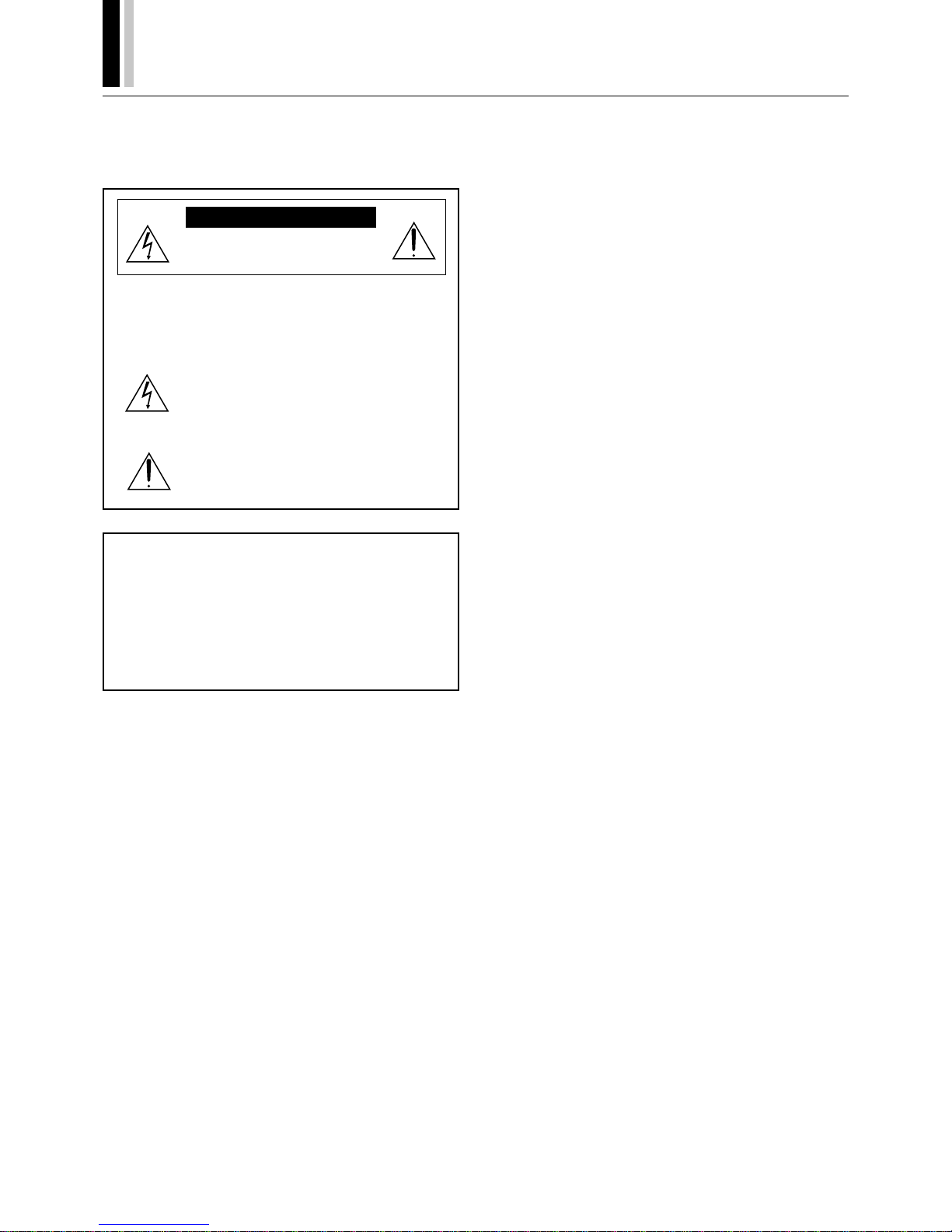
RISK OF ELECTRIC SHOCK
DO NOT OPEN
CAUTION:
TO REDUCE THE RISK OF ELECTRIC SHOCK, DO
NOT REMOVE COVER. NO USER-SERVICEABLE
PARTS INSIDE. REFER SERVICING TO QUALIFIED SERVICE PERSONNEL.
This symbol warns the user that uninsulated voltage within the unit may have sufficient magnitude
to cause electric shock. Therefore, it is dangerous
to make any kind of contact with any part inside of
this unit.
This symbol alerts the user that important literature concerning the operation and maintenance
of this unit has been included. Therefore, it should
be read carefully in order to avoid any problems.
WARNING
TO PREVENT FIRE OR SHOCK HAZARDS, DO NOT EXPOSE THIS UNIT TO RAIN OR MOISTURE. ALSO DO NOT
USE THIS UNIT'S POLARIZED PLUG WITH AN EXTENSION
CORD RECEPTACLE OR OTHER OUTLETS, UNLESS THE
PRONGS CAN BE FULLY INSERTED. REFRAIN FROM
OPENING THE CABINET AS THERE ARE HIGH-VOLTAGE
COMPONENTS INSIDE. REFER SERVICING TO QUALIFIED SERVICE PERSONNEL.
DOC compliance Notice
This Class A digital apparatus meets all requirements of the Canadian Interference-Causing Equipment Regulations.
WARNING
This equipment has been tested and found to comply with the limits for a Class A digital device, pursuant to Part 15 of the FCC
Rules. These limits are designed to provide reasonable protection
against harmful interference when the equipment is operated in a
commercial environment. This equipment generates, uses, and
can radiate radio frequency energy and, if not installed and used
in accordance with the instruction manual, may cause harmful interference to radio communications. Operation of this equipment
in a residential area is likely to cause harmful interference in which
case the user will be required to correct the interference at his own
expense.
Precautions
Please read this manual carefully before using your NEC plasma
monitor and keep the manual handy for future reference.
CAUTION
Page 4
PLASMA MONITOR
† 3
NOTE:
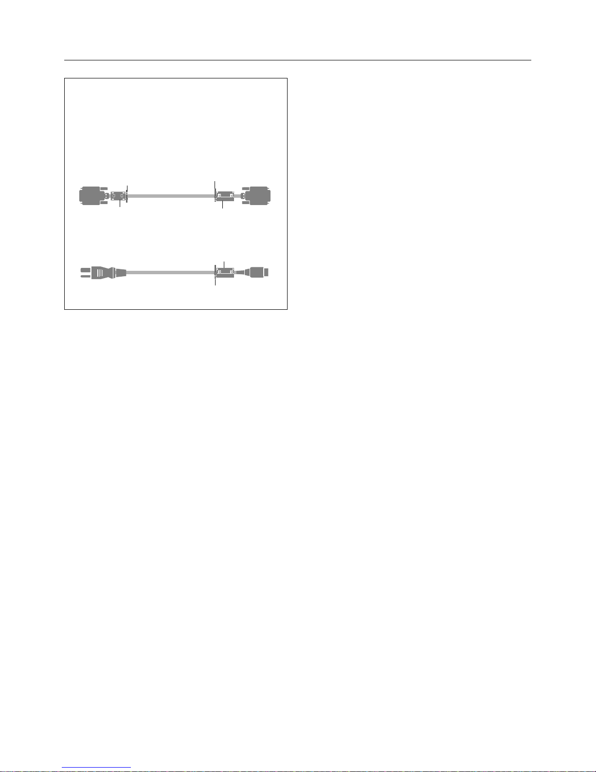
When you connect a computer to this monitor, attach the supplied ferrite cores. If you do not do this, this monitor will not
conform to mandatory FCC standards.
Attaching the ferrite cores.
Set the ferrite cores on both ends of the DVI cable (not supplied), and at one end of the power cable (supplied).
Close the lid tightly until the clamps click.
Set side
(Plasma Monitor side)
DVI cable (not supplied)
core (small)
core (small)
Connector
Power cable (supplied)
core (large)
band
band
band
Recommendations to avoid or minimize phosphor
burn-in
Like all phosphor-based display devices and all other gas plasma
displays, Plasma monitors can be susceptible to phosphor burn
under certain circumstances. Certain operating conditions, such
as the continuous display of a static image over a prolonged period of time, can result in phosphor burn if proper precautions are
not taken. To protect your investment in this NEC plasma monitor, please adhere to the following guidelines and recommendations for minimizing the occurrence of image burn:
* Always enable and use your computer's screen saver function
during use with a computer input source.
* Display a moving image whenever possible.
* Always power down the monitor when you are finished using it.
NEC has built-in several operating modes in your PlasmaSync PD
Series monitor to help you reduce the likelihood of phosphor burn.
These are called the AccuShield Phosphor Protection System. If
the Plasmasync monitor is in long-term use or continuous operation, use the functions available in AccuShield to reduce the likelihood of perceptible phosphor burn or to diminish its perceptible
effects if it occurs. See pages 37,45 and 46 for instructions on
how to use the Orbiter, Low Brightness and Inverse RGB modes
of AccuShield.
* Lower the Brightness and Contrast levels as much as possible
without impairing image readability.
* Display an image with many colors and color gradations (ie.
photographic or photo-realistic images).
* Create image content with minimal contrast between light and
dark areas. For example white characters on black backgrounds.
Use complementary or pastel colors whenever possible.
* Avoid displaying images with few colors and distinct, sharply
defined borders between colors.
Contact NEC Technologies at 1-800-836-0655 for other recommended procedures that will best suit your particular application
needs.
To avoid damage and prolong operating life:
1. Use only with 120V 50/60Hz AC power supply. Continued operation at line voltages greater than 120 Volts AC will shorten
the life of the unit, and might even cause a fire hazard.
2. Handle the unit carefully when installing it and do not drop.
3. Set the unit away from heat, excessive dust, and direct sunlight.
4. Protect the inside of the unit from liquids and small metal objects. In case of accident, unplug the unit and have it serviced
by an authorized NEC Service Center.
5. Do not hit or scratch the panel surface as this causes flaws on
the surface of the screen.
6. For correct installation and mounting it is strongly recommended to use a trained, authorized NEC dealer.
7. As is the case with any phosphor-based display (like a CRT
monitor, for example) light output will gradually decrease over
the life of a Plasma Display Panel.
Important Information
Page 5
4
†
PLASMA MONITOR
Mises en garde et précautions de sécurité
Le moniteur PlasmaSync NEC a été conçu et fabriqué pour une
utilisation fiable et durable. Il ne nécessite aucun entretien en dehors du nettoyage. Utiliser un chiffon doux et sec pour nettoyer la
surface de l'écran. Ne jamais utiliser de solvant comme l'alcool ou
le diluant. Le panneau à affichage plasma est constitué de fines
particules d'images ou pixels (cellules). Bien que NEC produise
des panneaux à affichage plasma avec plus de 99,99 % de cellules actives, il peut y avoir des cellules qui ne produisent pas de
lumière ou qui restent allumées.
Pour des raisons de sécurité et pour éviter d'endommager l'appareil,
lire attentivement les instructions suivantes.
Pour éviter les risques d'éléctrocution et d'incendie:
1. Laisser suffisament d'espace autour de l'appareil pour la ventilation et éviter toute augmentation excessive de la température
interne. Ne pas couvrir les évents ou l'installer dans un endroit
trop exigu.
L'appareil est équipé de ventilateurs de refroidissement. Si vous
installez l'appareil dans un espace clos, assurez-vous qu'il y
ait suffisamment d'espace au dessus pour permettre à l'air
chaud de s'élever et de s'évacuer.
Si la température du moniteur devient excessive, la protection
contre les surchauffes entrera en action et coupera
l'alimentation. Dans ce cas, éteindre l'appareil et débrancher
le câble d'alimentation. Si la température de la pièce dans
laquelle le moniteur est installé est particulièrement excessive,
déplacer l'appareil dans un endroit plus frais et le laisser refroidir
60 minutes. Si le problème persiste, prendre contact avec le
revendeur NEC pour le service après-vente.
2. Ne pas utiliser la fiche polarisée du cordon d’alimentation avec
des prolongateurs ou des prises de courant, sauf si les lames
peuvent être insérées à fond.
3. Ne pas exposer à L'eau ou à l’humidité.
4. Eviter d’endommager le cordon d’alimentation, et ne pas modifier le cordon d’alimentation.
5. Débrancher l’appareil pendant les tempêtes ou si l’appareil n’est
pas utilisé pendant une longue période.
6. Ne pas ouvrir le coffret. Des composants de haute tension se
trouvent à l’intérieur. Si l’appareil est endommagé de cette
manière, la garantie devient caduque. De plus, il y a risque
d’électrocution.
7. Ne pas essayer de réparer ou entretenir l’appareil soi-même.
NEC ne saura être tenu pour responsable pour toute blessure
ou dommage causé par des personnes non qualifiées qui
essayent de réparer ou d’ouvrir le couvercle arrière. Confier
toute réparation à un centre de service agréé NEC.
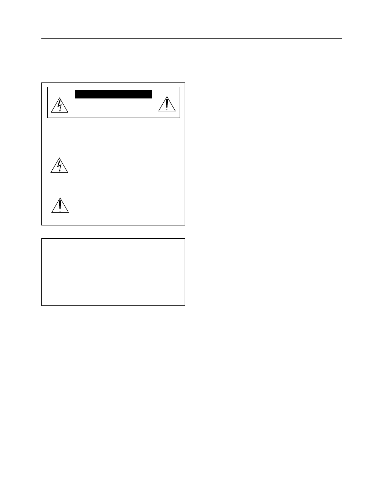
RISQUE D’ELECTROCUTION
NE PAS OUVRIR
MISE EN GARDE:AFIN DE REDUIRE LES RISQUES D’ELECTRO-CUTION, NE
PAS DEPOSER LE COUVERCLE, IL N’Y A AUCUNE PIECE UTILISABLE A L’INTERIEUR DE CET APPAREIL. NE CONFIER LES
TRAVAUX D’ENTRETIEN QU’A UN PERSONNEL QUALIFIE.
Ce symbole a pour but de prévenir l’utilisateur de
la présence d’une tension dangereuse, non isolée
se trouvant à l’intérieur de l’appareil. Elle est d’une
intensité suffisante pour constituer un risque
d’électrocution. Eviter le contact avec les pièces à
l’intérieur de cet appareil.
Ce symbole a pour but de prévenir l’utilisateur de
la présence d’importantes instructions concernant
l’entretien et le fonctionnement de cet appareil. Par
conséquent, elles doivent être lues attentivement
afin d’éviter des problèmes.
AVERTISSEMENT
AFIN DE REDUIRE LES RISQUES D’INCENDIE OU
D’ELECTROCUTION, NE PAS EXPOSER CET APPAREIL
A LA PLUIE OU A L’HUMIDITE. AUSSI, NE PAS UTILISER
LA FICHE POLARISEE AVEC UN PROLONGATEUR OU
UNE AUTRE PRISE DE COURANT SAUF SI CES LAMES
PEUVENT ETRE INSEREES A FOND. NE PAS OUVRIR LE
COFFRET, DES COMPOSANTS HAUTE TENSION SE
TROUVENT A L’INTERIEUR. LAISSER A UN PERSONNEL
QUALIFIE LE SOIN DE REPARER CET APPAREIL.
DOC avis de conformation
Cet appareil numérigue de la classe A respecte toutes les
exigences du Réglement sur le Matériel Brouilleur du Canada.
AVERTISSEMENT
Cet équipement a été testé et certifié conforme avec les limitations des équipements numériques de Classe A, conformément à
l'article & (du règlement FCC. Ces limites sont conçues pour assurer une protection raisonnable contre les interférences nuisibles
lorsque l'équipement est utilisé en milieu commercial. Cet
équipement génère, utilise, et peut produire de l'énergie de
fréquence radio et, s'il n'est pas installé et utilisé selon le manuel
d'instruction, peut provoquer des interférences nuisibles aux communications radio. L'utilisation de cet équipement dans une zone
résidentielle est susceptible de provoquer des interférences
nuisibles, dans quel cas l'utilisateur est tenu de remédier à ces
interférences à ses frais.
Précautions
Veuillez lire ce manuel avec attention avant d'utiliser votre
PlasmaSync NEC moniteur et conserver ce manuel à portée de la
main pour une consultation ultérieure.
ATTENTION
Important Information
Page 6
PLASMA MONITOR
† 5
REMARQUE:
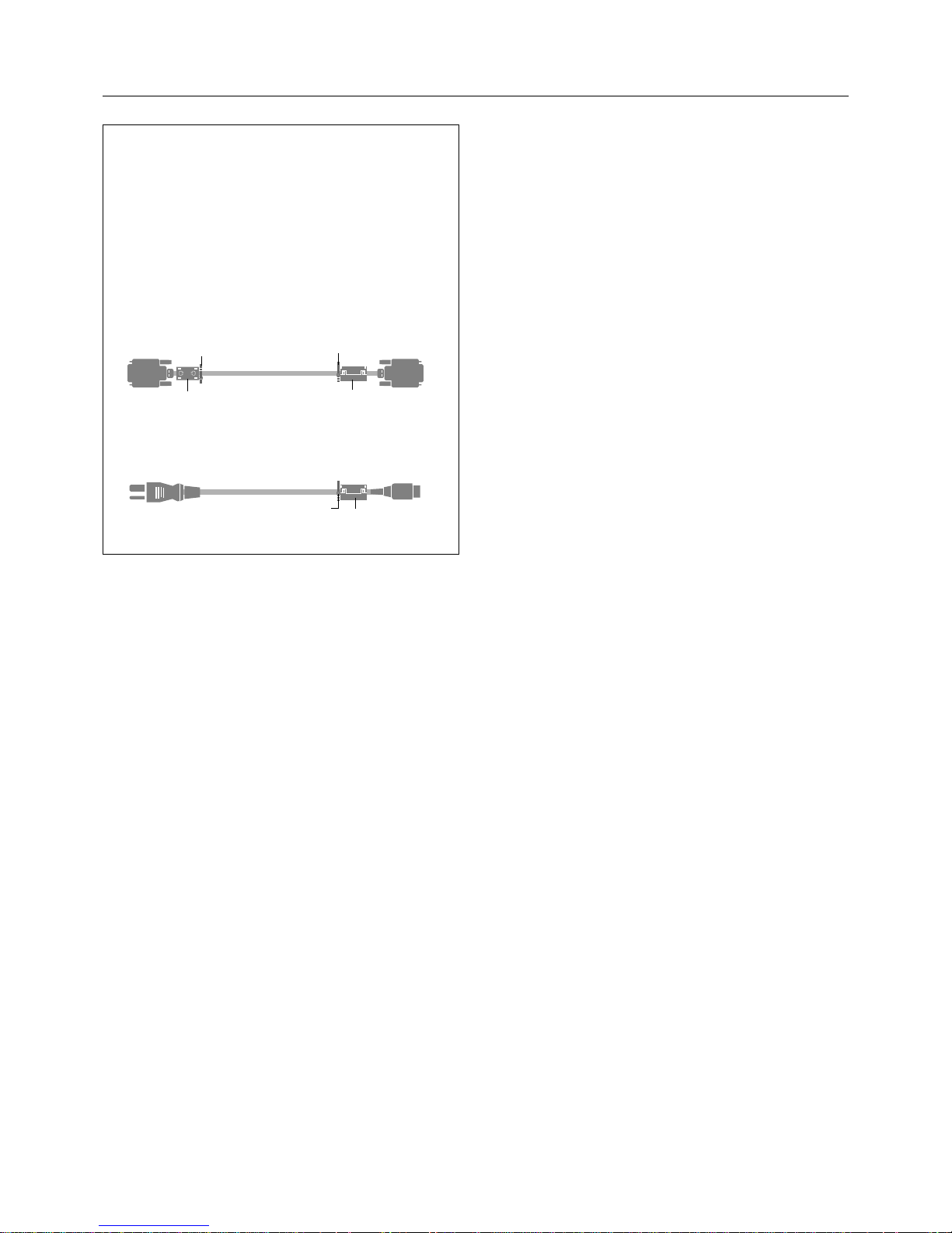
Lorsque vous branchez un micro-ordinateur sur ce moniteur,
fixez les noyaux en ferrites fournis. Si vous ne le faîtes, le
moniteur ne sera pas en conformité avec les exigences des
standards FCC.
Fixation des noyaux en ferrite.
Installez les noyaux en ferrite sur chaque bout du câble DVI
(non fourni), ainsi que sur un côté du câble d’alimentation
électrique (fourni).
Fermez doucement le couvercle jusqu’à ce que les crans se
clipsent.
Utilisez le collier plastique pour fixer la tore en ferrite.
Pour éviter le risque de combustion au phosphore,
les mesures suivantes sont recommandées
Comme tous les appareils d'affichage à base de phosphore et
tous les autres affichages à gaz plasma, les moniteurs Plasma
peuvent être sujets à la combustion au phosphore dans certaines
circonsatnces. Certaines conditions d'utilisation, telles que
l'affichage continu d'une image statique pour une durée prolongée,
peuvent causer des brûlures au phophore si aucune précaution
n'est prise. Pour protéger votre investissement dans ce moniteur
Plasma NEC, veuillez suivre les directives et les recommandations
suivantes pour minimiser l'occurence de brûlure d'image :
* Assurez-vous de mettre en marche et d'utliser l'économisateur
d'écran chaque fois que c'est possible lorsque vous l'utilisez avec
une source d'entrée d'ordinateur.
* Affichez une image en mouvement aussi souvent que possible.
* Coupez toujours l'alimentation lorsque vous avez terminé
d'utiliser la moniteur.
NEC a installé de nombreux modes d’opération dans votre moniteur
de série PlasmaSync PD afin de minimiser les risques de combustion au phosphore. Ce système de protection a pour nom
Système de Protection Phosphore AccuShield. Si le moniteur
PlasmaSync est en usage pendant de longues périodes ou en
utilisation continue, veuillez utiliser les fonctions disponibles dans
le AccuShield pour minimiser les risques de combustion au phosphore notable, ou pour en minimiser les conséquences si elle
apparaît. Référez-vous aux pages 37,45 et 46 pour plus de détails
sur l’utilisation des modes Orbiter, Illumination Réduite et RVB Inverse de l’AccuShield.
* Abaissez le niveau de l'image (contraste, luminosité) autant que
possible, sans faire perdre la lisibilité de l'image.
* Affichez une image avec de nombreuses couleurs et gradua-
tions de couleur (par ex. des images photographiques ou photo-
réalistes).
*Créez un contenu d'image avec un contraste minimal entre les
zones sombres et les zones claires. Par exemple, des caractères
blancs sur un fond noir. Utilisez des couleurs complémentaires
ou pastels le plus souvent possible.
* Évitez d'afficher des images avec peu de couleurs et des limites
nettes et clairement définies entre les couleurs.
Contactez NEC Technologies au 1-800-836-0655 pour d'autres
procédures recommandées qui conviendront le mieux au besoin
de votre appareil.
Pour éviter des dommages et prolonger la durée de
service de l’appareil:
1. N’utiliser qu’une source d’alimentation de 120 V 50/60 Hz CA.
Le fait d’utiliser l’appareil en continu à des tensions de ligne
supérieures à 120 Volts CA réduit sa durée de vie et risque de
provoquer un incendie.
2. Manipuler l’appareil avec soin pendant son déplacement et ne
pas le faire tomber.
3. Eloigner l’appareil des endroits chauds, très poussiéreux et
exposés en plein soleil.
4. Eviter que des liquides et des petits objets métalliques
pénètrent à l’intérieur de l’appareil. En cas d’accident,
débrancher l’appareil et le confier à un centre de service agréé
NEC.
5. Ne pas frapper ou rayer la surface de la écran plasma, car des
défauts risquent de se produire sur la surface de la écran
plasma.
6. Pour effecteur une installation et un montage corrects, il est
recommandé de faire appel au concessionnaire NEC autorisé
et spécialisé.
7. Comme c'est le cas pour tout affichage à base de phosphore
(comme un moniteur CRT, par exemple), la puissance de
lumière baisse graduellement au cours de la vie du Panneau
d'Affichage à Plasma.
Câble DVI (non fourni)
noyau (petit)
noyau (petit)
connecteur
câble d’alimentation électrique
(fourni)
côté de l’appareil
(côté du moniteur à plasma)
noyau (large)
Collier plastique
Collier plastique
Collier plastique
Important Information
Page 7
6
†
PLASMA MONITOR
NEC Technologies, Inc. (hereinafter NECTECH) warrants this product to be free from defects in material and workmanship under the
following terms and, subject to the conditions set forth below, agrees
to repair or replace (at NECTECH's sole option) any part of the
enclosed unit which proves defective. Replacement parts or products may be new or refurbished and will meet specifications of the
original parts or products.
HOW LONG IS THE WARRANTY?
Parts and labor are warranted for (1) One Year from the date of
the first customer purchase.
WHO IS PROTECTED?
This warranty may be enforced only by the first purchaser.
WHAT IS COVERED AND WHAT IS NOT COVERED
Except as specified below, this warranty covers all defects in material or workmanship in this product. The following are not covered by the warranty:
1. Any product which is not distributed in the U.S.A. or Canada
and Mexico by NECTECH or which is not purchased in the
U.S.A. or Canada or Mexico from an authorized NECTECH
dealer.
2. Any product on which the serial number has been defaced,
modified or removed.
3. Damage, deterioration or malfunction resulting from:
a. Accident, misuse, abuse, neglect, fire, water, lightning or
other acts of nature, unauthorized product modification, or
failure to follow instructions supplied with the product.
b. Repair or attempted repair by anyone not authorized by
NECTECH.
c. Any shipment of the product (claims must be presented to
the carrier).
d. Removal or installation of the product.
e. Any other cause which does not relate to a product defect.
f. Burns or residual images upon the phosphor of the panel.
4. Cartons, carrying cases, batteries, external cabinets, magnetic
tapes, or any accessories used in connection with the product.
5. Service outside of the U.S.A. , Canada and Mexico.
WHAT WE WILL PAY FOR AND WHAT WE WILL
NOT PAY FOR
We will pay labor and material expenses for covered items, but we
will not pay for the following:
1. Removal or installation charges.
2. Costs of initial technical adjustments (set-up), including adjustment of user controls. These costs are the responsibility of
the NECTECH dealer from whom the product was purchased.
3. Payment of shipping charges.
HOW YOU CAN GET WARRANTY SERVICE
1. To obtain service on your product, consult the dealer from whom
you purchased the product.
2. Whenever warranty service is required, the original dated invoice (or a copy) must be presented as proof of warranty coverage. Please also include in any mailing your name, address
and a description of the problem(s).
3. For the name of the nearest NECTECH authorized service
center, call NECTECH at 800-836-0655.
LIMITATIONS OF LIABILITY
Except for the obligations specifically set forth in this warranty statement, we will not be liable for any direct, indirect, special, incidental, consequential, or other types of damages, whether based on
contract, tort, or any other legal theory, whether or not we have
been advised of the possibility of such damages.
This warranty is in lieu of all other warranties express or implied,
including, but not limited to, the implied warranties of merchantability or fitness for a particular purpose.
EXCLUSION OF DAMAGES
NECTECH' s liability for any defective product is limited to the repair or replacement of the product at our option. NECTECH shall
not be liable for:
1. Damage to other property caused by any defects in this product, damages based upon inconvenience, loss of use of the
product, loss of time, commercial loss; or
2. Any other damages whether incidental, consequential or otherwise. Some states do not allow limitation on how long an
implied warranty lasts and/or do not allow the exclusion or limitation of incidental or consequential damages, so the above
limitations and exclusions may not apply to you.
HOW STATE LAW RELATES TO THE WARRANTY
This warranty gives you specific legal rights, and you may also
have other rights which vary from state to state.
FOR MORE INFORMATION,
TELEPHONE 800-836-0655
NEC TECHNOLOGIES, INC.
1250 N. Arlington Heights Road, Suite 500
Itasca, Illinois 60143-1248
NOTE: All products returned to NECTECH for service MUST have prior approval. To get approval, call NEC Technologies at 800-836-0655.
Limited Warranty Plasma Monitors
Page 8

PLASMA MONITOR
† 7
Contents
Important Information ...................................................................................................................... 2
Limited Warranty Plasma Monitors ................................................................................................. 6
Contents ........................................................................................................................................... 7
How to Attach Options to the Plasma Monitor ................................................................................. 8
Introduction ...................................................................................................................................... 9
Part Names and Functions ............................................................................................................. 10
Control Panel ................................................................................................................................................. 10
Terminal Panel ................................................................................................................................................11
Remote Control .............................................................................................................................................. 12
Operating Range for the Remote Control .......................................................................................................12
Setup Procedure ............................................................................................................................................13
Connections ................................................................................................................................... 14
Wiring Diagram ..............................................................................................................................................14
Connecting Your PC or IBM compatible ........................................................................................................15
Connecting Your Macintosh Computer .......................................................................................................... 16
Connections with Equipment that has a Digital Interface ...............................................................................17
Connecting Your VCR ....................................................................................................................................18
Connecting Your DVD Player.......................................................................................................................... 19
Connecting Your Stereo Amplifier ..................................................................................................................20
Basic Operation .............................................................................................................................. 21
Turning on the Main Power and Return to Standby Mode ............................................................................. 21
Turning On or Off the Power with the Remote Control ...................................................................................21
Power Management Function ........................................................................................................................22
Selecting a computer or video source ............................................................................................................22
Menu Operations (On-screen Menu)............................................................................................... 23
Buttons Used in Menu Operations .................................................................................................................25
Operation of the Menu Screen .......................................................................................................................25
Configuration Menu (CONFIG MENU) ............................................................................................. 26
Audio Settings (SOUND) ................................................................................................................. 27
Picture Adjustments (VISUAL CONTROL) ....................................................................................... 28
Auto Picture/Wide Screen Settings (AUTO PICTURE)..................................................................... 29
Clock Frequency/Clock Phase Adjustment, and RGB Mode Adjustment (AUTO PICTURE) ..........................29
Wide Screen Setting (WIDE MODE) ............................................................................................................... 30
Horizontal/Vertical Position Adjustments (H-POSITION and V-POSITION) ...................................... 31
Direct Adjustment ...........................................................................................................................................31
Menu Adjustments .........................................................................................................................................32
Input Selection (INPUT SELECT) .................................................................................................... 33
Standard Settings (NORMAL).......................................................................................................... 34
Information Screen (DISPLAY MODE) ............................................................................................. 35
Timer Settings (PRESENT TIME) .................................................................................................... 36
Time Settings .................................................................................................................................................36
Timer Settings ................................................................................................................................................36
4-Screen/9-Screen Multiple System Settings (VIDEO WALL MENU)............................................... 38
Menu Display Position Adjustment (OSM LOCATION) ..................................................................... 39
Other Functions (OTHER SETTINGS) .............................................................................................. 40
Color System Settings (COLOR SYSTEM) .....................................................................................................40
Power-On Mode Setting (P-ON MODE) .........................................................................................................40
Power Management Settings (POWER MANAGER) .......................................................................................41
POWER/STANDBY Indicator ...................................................................................................................42
ID Number Setting (SET ID NO) ..................................................................................................................... 43
RGB 3 Adjustment (RGB 3 ADJUST) .............................................................................................................43
Cinema Mode Setting (CINEMA MODE) .........................................................................................................44
Long Life Settings (LONG LIFE MODE) ........................................................................................... 45
Long Life Settings (LONG LIFE MODE) ..........................................................................................................45
Gray Level Settings (GRAY LEVEL) ................................................................................................................46
Color Temperature Adjustment (COLOR TEMP) ............................................................................. 47
Appendix ........................................................................................................................................ 48
Opening the Terminal Cover ...........................................................................................................................48
Removing the Terminal Cover ........................................................................................................................48
Mounting of the Remote Control Holder ........................................................................................................ 48
Placing the Remote Control into the Remote Control Holder .........................................................................49
Extending the Simple Feet ............................................................................................................................. 49
Attaching the Ferrite Cores ............................................................................................................................ 50
Pin Configuration and Signal Level of Mini D-Sub 15-Pin (Analog) Input Connector ......................................51
Pin Configuration and Functions of External Control Connector (Mini D-Sub 9 -Pin) ..................................... 51
Command Reference List ........................................................................................................................53
Pin Configuration and Signal of the RGB 3 IN Connector (DVI Connector) ....................................................64
Optional Accessories ..................................................................................................................................... 64
Signal Identification For Raster Preset............................................................................................................65
Specifications ................................................................................................................................................. 66
Troubleshooting.............................................................................................................................................. 67
Cabinet dimensions .......................................................................................................................................69
Page 9
8
†
PLASMA MONITOR
How to Attach Options to the Plasma Monitor
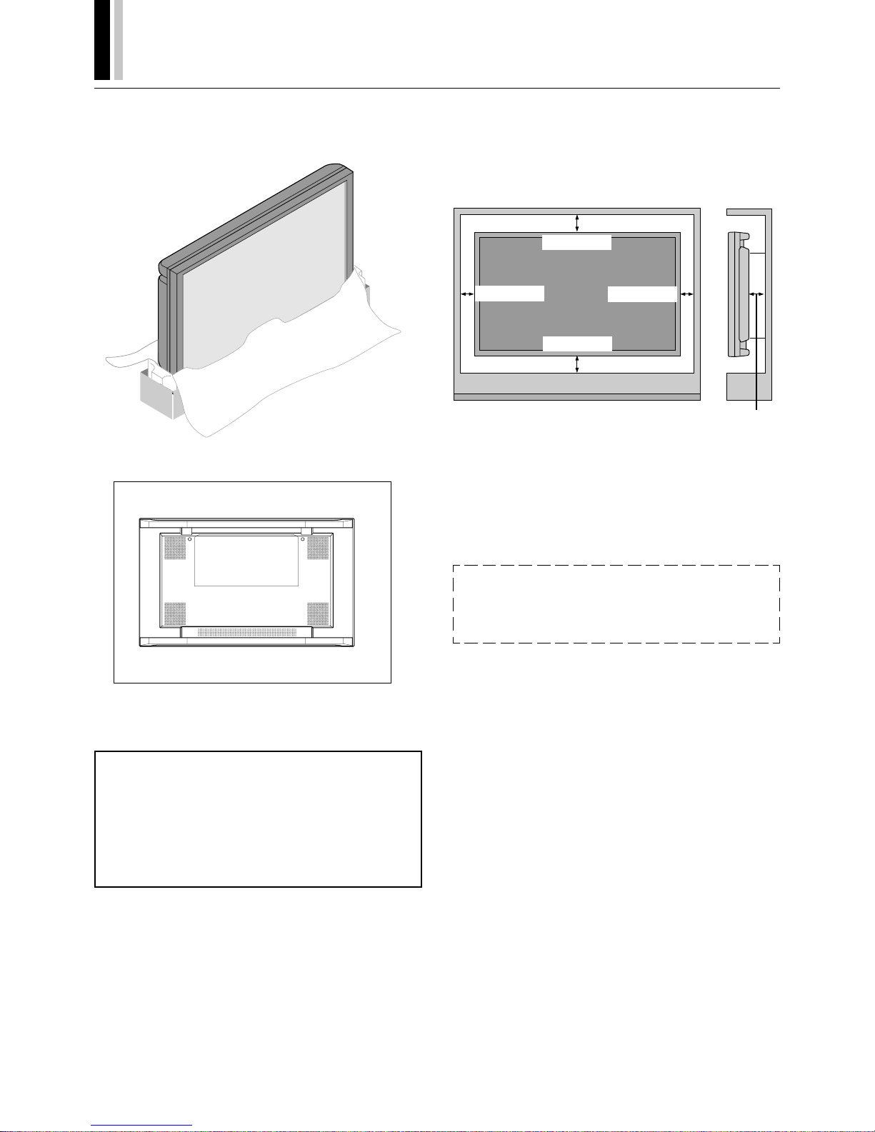
You can attach your optional mounts or stand to the plasma monitor in one of the following two ways:
In the upright position.
Lay the screen face down.
Lay the protective sheet, which was wrapped around the monitor
when it was packaged, beneath the screen surface so as not to
scratch the screen face.
This device cannot be used or installed without a separate
Tabletop Stand or other optional mounting accessory. For
proper installation it is strongly recommended to use a
trained, NEC authorized service person. Failure to follow
correct mounting procedures could result in damage to the
equipment or injury to the user or installer. Product warranty does not cover damage caused by improper installation. Failure to follow these recommendations could result in voiding your warranty.
Ventilation Requirements for enclosure
mounting
To allow heat to disperse, leave space between surrounding objects as shown in the diagram to the right.
50mm (1.97”)
50mm (1.97”)
31mm (1.22”)
31mm (1.22”)
45mm
(1.77”)
Pulling Out and Reinserting the Retractable Feet
Notice:
See "Extending the Simple Feet" on page 49.
* Installation of only the main unit is not possible. Be sure to use
and install the main unit in conjunction with a stand or special
unit.
NOTE: RETRACTABLE FEET ARE FOR TEMPORARY USE ONLY AND ARE
NOT INTENDED FOR PERMANENT INSTALLATION.
MODEL # PX-42VPU1-ST STAND IS REQUIRED FOR PERMANENT TABLETOP INSTALLATION.
REPLACE THE FEET WHEN YOU MOVE THE MONITOR.
Page 10

PLASMA MONITOR
† 9
OSM and IPM are trademarks of NEC Technologies, Inc.
IBM PC/AT, PS/2, VGA, S-VGA, 8514/A and XGA are registered
trademarks of International Business Machines Corporation.
Apple and Macintosh are registered trademarks of Apple Computer, Inc.
Microsoft is a registered trademark of Microsoft Corporation. Windows is a trademark of Microsoft Corporation.
Introduction to the PlasmaSync 50PD2
This section introduces you to your new PlasmaSync 50PD2, provides a list of materials that comes with your monitor and describes
the features and controls.
The features you’ll enjoy include:
* This unit can be used with IBM PC/AT, Macintosh, and com-
patibles.
(For details, see “Factory Setting Values Preset Table.” Pg.63)
* Easy-to-operate remote control and external control connector.
* Wired/Wireless Remote Control PX-RC2U (optional) can be used
as a wireless or as a wired remote control (with automatic switch-
ing by cable connection) and the remote THROUGH OUT con-
nector permits simultaneous operation of multiple monitors.
(A maximum of 3 units can be connected.)
The external control connector with a THROUGH OUT feature
permits various control functions to be made externally.
* ID No. settings can be made for up to 256 units.
* NTSC, PAL, SECAM, and M-NTSC composite video signals can
be accommodated
Video signals from video cameras, video decks, video disc play-
ers, and other video equipment adhering to NTSC as well as
PAL, SECAM, and M-NTSC (with a 4.43 MHz chroma signal)
standards can be selected on screen.
* Varied set of input/output connectors
• Video input/output: BNC video connector, S-video connector.
Each type is equipped with its own THROUGH OUT connector, single system.
• Analog RGB input: mini D-Sub 15-pin connector, BNC (G, B,
R, H/CS, V connectors). BNC is equipped with its own
THROUGH OUT connector, single system.
• DVD/HD input/output: BNC (Y, Cb/Pb, Cr/Pr connectors)
BNC is equipped with its own THROUGH OUT connector,
single system.
• Audio input signals: Stereo RCAx2
• Audio output signals: Stereo RCAx1
* Component video input terminal for DVD, 15.75 kHz (Y,Cb,Cr)
* You can select RGB source or Component source for the 5BNC
terminal (RGB2/DVD/HD). When selecting an RGB input, the
source is switched to the RGB input when selecting a compo-
nent input, the source is switched to the DVD/HD input.
* Can be used with Digital RGB input (DVI standard compliant)
* The signale plasma monitor provides four split screen feature.
* Can be used with multiple screens : 4-screen and 9-screen
VIDEO WALL (For 9-screen, an optional distribution amplifier is
needed for VIDEO WALL )
* Power management function
RGB3 input mode complies with DMPM (Digital Monitor Power
Management) of DVI.
A great reduction in power consumption when not being used is
achieved through the VESA-proposed DPMS system.
The unit can also be used with the Energy Star standard (in
which case power consumption will be 15 W or less when not
being used).
* The personal computer and the operating system that are to be
connected must be compatible with VESA DPMS.
Personal computers that are to be connected to the RGB3 input
must be compatible with DVI DMPM.
Introduction
* OSM (On Screen Manager) function
The OSM function displays a variety of screen adjustment and
correction menus on the screen to allow fine settings to be made.
* Plug and Play compatible
Plug and Play supports VESA DDC1 and DDC level B.
(VESA DDC1 and DDC2 level B)
The RGB3 input is compatible with DDC2 level B only.
* Can be used with RS-232C
* IBM PC/AT is a registered trademark of International Busi-
ness Machines Corporation.
* Macintosh is a registered trademark of Apple Computer, Inc.
* VESA is a trademark of Video Electronics Standard Associa-
tion.
* DVI is an abbreviation for Digital Visual Interface.
Contents of the Package
The following lists all of the items included in your plasma monitor
package. Please save the original box and packing materials for
future transportation or shipment of this monitor.
1. Plasma monitor1
2. Power cable1
3. Wireless remote control1
4. AA battery2
5. Remote control holder1
6. RGB signal cable
(mini D-sub 15-pin to mini D-sub 15-pin)1
7. Stopper2 *
8. Screw2 *
9. Ferrite core (large)1
10. Ferrite core (small)2
11. User's manual1
* These are fittings for fastening the unit to a wall to prevent tip-
ping due to external shock when using the stand (option).
Fasten the safety fittings to the holes in the back of the monitor
using the safety fitting mount screws.
Option
• Wired/ Wireless Remote Control
• Wall mount unit
• Ceiling mount unit
• Tilt mount unit
• Tabletop stand
• Others
Page 11
10
†
PLASMA MONITOR
POWER/STANDBY
RGBVIDEO EXITDOWNUPPROCEED
1
Part Names and Functions
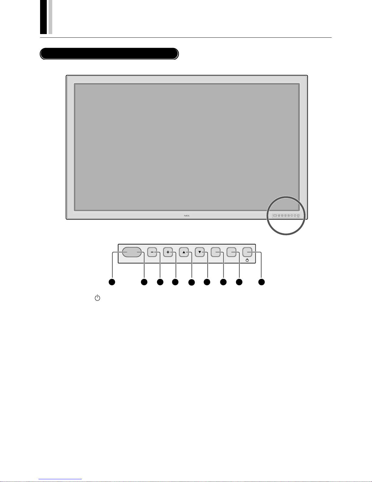
Control Panel
234
5
67
8
9
q POWER button ( )
Switches the main power on/off. See also page 21.
w EXIT button
Exits the on-screen menu (OSM) mode. See also page 25.
e PROCEED button
Sets the on-screen menu (OSM) mode and displays the onscreen menu. See also page 25.
r DOWN (▼) button
Functions as the ▼ button in the on-screen menu (OSM) mode.
See also page 25.
t UP (▲)button
Functions as the ▲ button in the on-screen menu (OSM) mode.
See also page 25.
y RGB (+) button
Switches to the signal connected with the RGB input connector. (Toggle switches between [RGB1], [RGB2] / [DVD/HD], or
[RGB3].)
Functions as the (+) button in the on-screen menu (OSM) mode.
See also pages 22 and 25.
u VIDEO (–) button
Switches to the signal connected with the VIDEO input connector.
Functions as the (–) button in the on-screen menu (OSM) mode.
See also pages 22 and 25.
i Remote control sensor
Receives the signal from the remote control (when using the
wireless remote control). See also page 12.
o POWER/STANDBY
The lamp color indicates the mode of power on/standby or
power management. See also page 21.
*When the "CONTROL LOCK" toggle switch on the monitor's
input panel is set to "ON", the buttons on the set's front bezel
control panel do not function.
Page 12
PLASMA MONITOR
† 11
Part Names and Functions
AUDIO
OUT
LR
AUDIO
IN 2
L
(
MONO
)
R
VIDEO
OUT
S-VIDEO VIDEO
AUDIO IN 1
EXTERNAL CONTROL
RGB 1
L
(
MONO
)
RIN
IN OUT
IN
OUT
IN
RGB 2
/
DVD
/
HD
G
/
Y B
/
C
B
/
P
B
H
/
CS VR
/
C
R
/
P
R
REMOTE
RGB 3
AC IN
IN OUT
C
/
L
IN
1
2
6
7
8
9
10
11
3
4
5
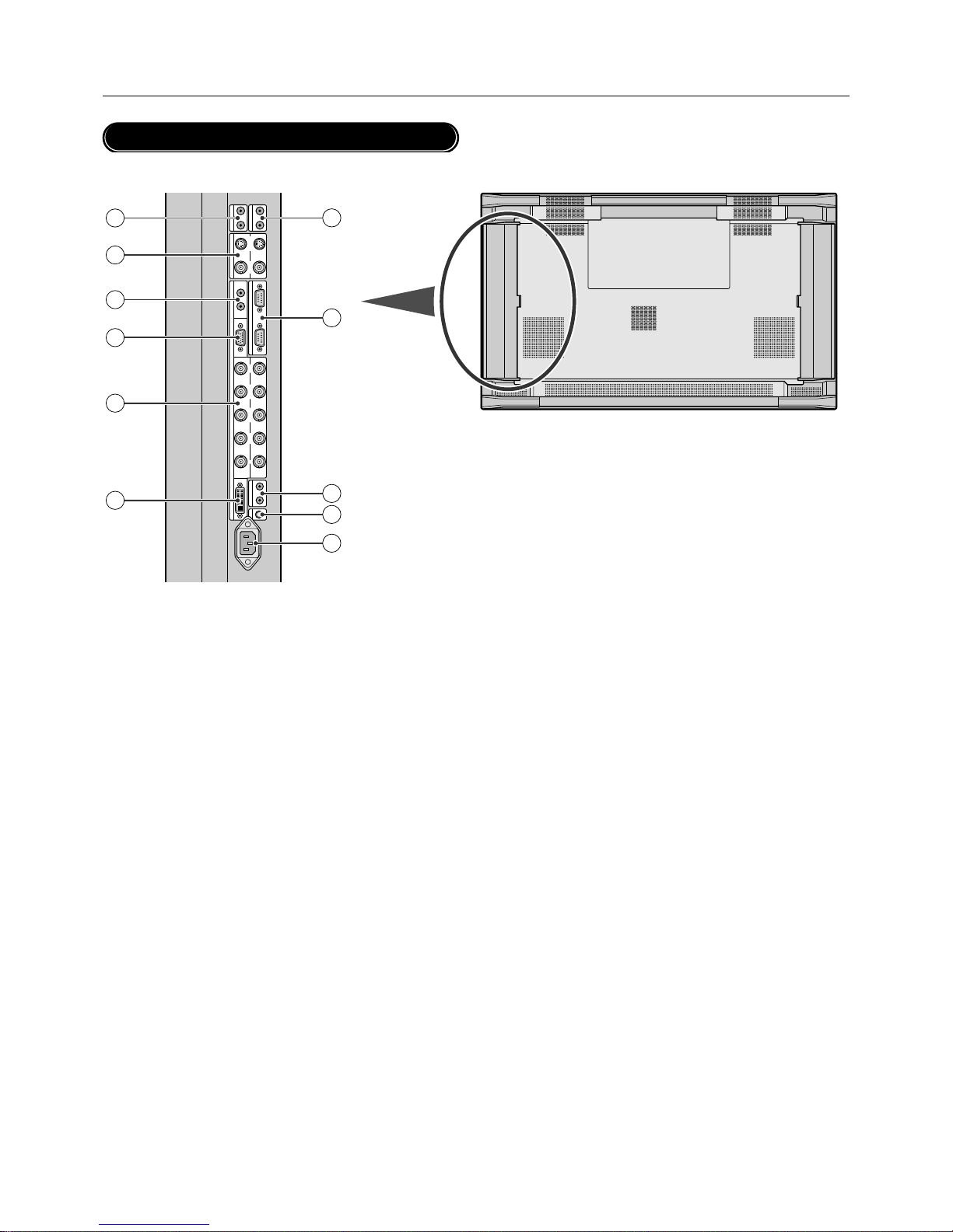
Terminal Panel
q AC IN connector
Connects with the supplied power cable.
w CONTROL LOCK
When "CONTROL LOCK" is set to "ON", the buttons on the
set's front bezel control panel do not function.
e REMOTE (Mini jack)
IN jack: When you use the remote control with a wire, attach it
here.
OUT jack: You can use this jack to output the remote control
signal from the REMOTE IN jack.
* This is used when operating multiple monitors (this plasma moni-
tor) with a single remote control.
r EXTERNAL CONTROL (mini D-Sub 9 pin)
IN connector: Use when operating the plasma monitor from
the optional equipment with EXTERNAL CONTROL.
OUT connector: You can use this connector to output the signal from the EXTERNAL CONTROL IN connector.
t AUDIO OUT
You can use this jack to output the audio signal from the AUDIO IN 1 or 2 jack.
y AUDIO IN 2
This is your audio input from your equipment such as a computer, VCR or DVD player.
u VIDEO
VIDEO IN connector (BNC): Here is where you connect a
composite video signal.
VIDEO OUT connector (BNC): You can use this connector to
output the composite video signal from the VIDEO IN connector.
S-VIDEO IN connector (DIN 4 pin): Here is where you connect the S-video (Y/C separate signal).
* When connections are made to both the VIDEO connector and
the S-VIDEO connector, the signal of the S video connector
has priority.
S-VIDEO OUT connector (DIN 4 pin): You can use this connector to output the S-video signal from the S-VIDEO IN connector.
i AUDIO IN
This is your audio input from your equipment such as a computer, VCR or DVD player.
o RGB 1 IN (mini D-Sub 15 pin)
Connect the analog RGB signal of a personal computer or other
RGB equipment.
!0 RGB 2/DVD/HD [G/Y, B/Cb/Pb, R/Cr/Pr, H/CS, V] (BNC)
IN connector: Connect the analog RGB signal or other RGB
equipment.
The H/V composite signal is connected to the H/CS connector. Also this connects with your equipment such as a DVD
player and HDTV laser disk player. A Sync-on-Green signal
can be connected to the G/Y connector
OUT connector: You can use this connector to output the signal from the RGB 2/DVD/HD IN connector.
!1 RGB 3 IN (DVI-I 29 pin)
Connects a digital RGB signal of a personal computer with a
digital RGB output.
*This connector does not support analog input.
Page 13
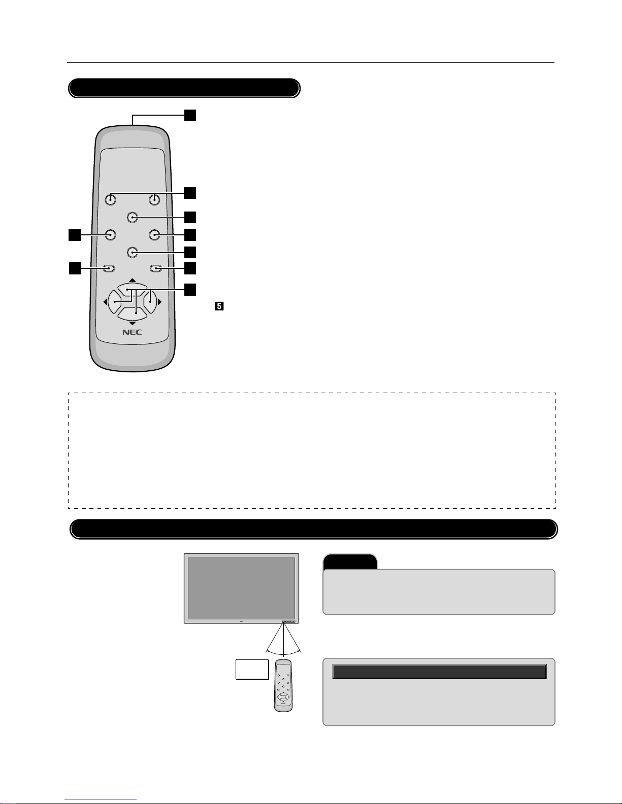
12
†
PLASMA MONITOR
Part Names and Functions
POWER OFF
RGB 1
POWER ON
RGB 3
RGB 2/DVD/HD
VI DEO
EXI T
PROCEED
POSITION/CONTROL
RP-102
9
2
8
4
3
5
1
7
6
NOTE:
* The wired/wireless remote control PX-RC2U is available as an option.
* In addition to the features on the supplied remote control, the optional remote control has the following functions:
• Direct remote button operation for picture adjustments such as contrast and brightness.
• Direct remote button operation for picture and alignment adjustments such as horizontal and vertical position.
• When the remote control is connected to the REMOTE IN jack with the remote cable, the optional remote control can be used as the wired remote control.
The REMOTE OUT connector is used to connect multiple plasma monitors together and allows all of the plasma monitors to be controlled by one remote
control.
• When you control multiple plasma monitors by the single remote control, you can assign an ID number to each plasma monitor so that all of the plasma
monitors are not be affected at the same time.
POWER OFF
RGB 1
POWER ON
RGB 3
RGB 2/DVD/HD
VIDEO
EXIT
PROCEED
POSITION/CONTROL
RP-102
Important
The remote control system may not function when direct sunlight or strong
illumination strikes the remote control sensor of the plasma monitor, or
when there is an obstacle in the path. Should this happen, use the remote
control in the wired operation.
Handling the remote control
Remote Control
¡ POWER ON/OFF button
Switches the power on/off. See also
page 21.
* If the POWER/STANDBY lamp is not
glowing, then these controls will not
work.
™ RGB 1 button
Select the RGB1 input. See also page
22.
£ RGB 2 button
Select the RGB 2/DVD/HD input. See
also page 22.
¢ RGB 3 button
Select the RGB 3 input. See also page
22.
VIDEO button
Select the VIDEO input. See also page
22.
§ POSITION/CONTROL buttons
Adjust the image location horizontally and vertically. See also pages 25 and 31.
These buttons executes the menu selection and
confirms adjustments/setting in the menu mode.
¶ PROCEED button
Displays the on-screen menu (Menu mode).
See also page 25.
• EXIT button
Exits the on-screen menu or Menu mode. See
also page 25.
ª Infrared transmitter
Direct the remote control toward the remote
sensor on the plasma monitor. See also page
12.
Operating Range for the Remote Control
Point the top of the remote
control toward the plasma
monitor's remote sensor
during button operation.
Use the remote control
within a distance of about 7
m/23 ft. from the front of the
plasma monitor's remote
control sensor and at a horizontal and vertical angle of
within 30˚.
Approx.
7m/23ft
30˚ 30˚
* Do not subject to strong shock.
* Do not allow water or other liquid to splash the remote con-
trol. If the remote control gets wet, wipe it dry immediately.
* Avoid exposure to heat and steam.
Page 14
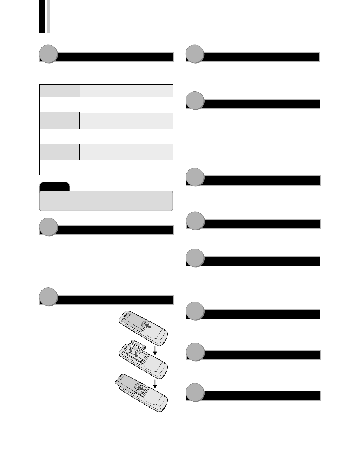
PLASMA MONITOR
† 13
11
10
9
8
7
6
5
4
3
2
1
Setup Procedure
Determine the installation location
Installation of only the plasma monitor is not possible. Be sure to
use and install the plasma monitor in conjunction with a stand or
special unit.
CAUTION
DO NOT ATTEMPT TO INSTALL THE
PLASMA MONITOR.
Installing your plasma display must be done by a qualified technician. Contact your dealer for more information.
CAUTION
DO NOT USE THE RETRACTABLE FEET
FOR PURPOSE OF PERMANENT INSTALLATION.
The retractable feet are for temporary use only and are not intended for permanent installation.
CAUTION
MOVING OR INSTALLING THE PLASMA
MONITOR MUST BE DONE BY TWO OR
MORE PEOPLE.
Failure to follow this caution may result in injury if the plasma
monitor falls.
Important
Lay the protective sheet, which was wrapped around the plasma monitor
when it was packaged, beneath the plasma monitor so as not to scratch the
panel.
Install the plasma monitor
The connections of two or more plasma monitors may degrade
image quality on the remaining connected units connected to the
loop out. Consider the cable length or cable type to be used.
Note that only one plasma monitor connection is possible for loopout.
Install the remote control batteries
The remote control is powered by 1.5
V AA magnesium batteries.
To install or replace batteries:
¡ Press and slide to open the cover.
™ Align the batteries according to
the (+) and (–) indications inside
the case.
£ Replace the cover.
Connect external equipment (See page 14)
• To protect the connected equipment, turn off the main power
before making connections.
• Refer to your equipment user manual.
Connect the supplied power cable
• The power outlet socket should be installed as near to the equipment as possible, and should be easily accessible.
• Attach the supplied ferrite core to the power cable. See page
50.
• Fully insert the prongs into the power outlet socket. Loose connection may cause noise.
• The maximum power consumption 570 W (the maximum current rating 6.0 A)
Switch on the power of all the attached external equipment
When connected with a computer, switch on the power of the computer first.
Operate the attached external equipment.
Display the signal on the external equipment you wish.
Select the input mode (See pages 22 and 27)
Select the appropriate input.
When the equipment is connected to the RGB 2/DVD/HD, make
the setting for the RGB 2 input. When an audio signal is connected,
make the setting for sound.
Adjust the sound (See page 27)
Make adjustments when adjustment of the volume or balance is
required.
Adjust the screen (See pages 31 and 32)
Make adjustments when adjustment of the screen display position
or distortion is required.
Adjust the image (See page 28)
Make adjustments when picture adjustment such as the brightness or contrast is required.
Page 15
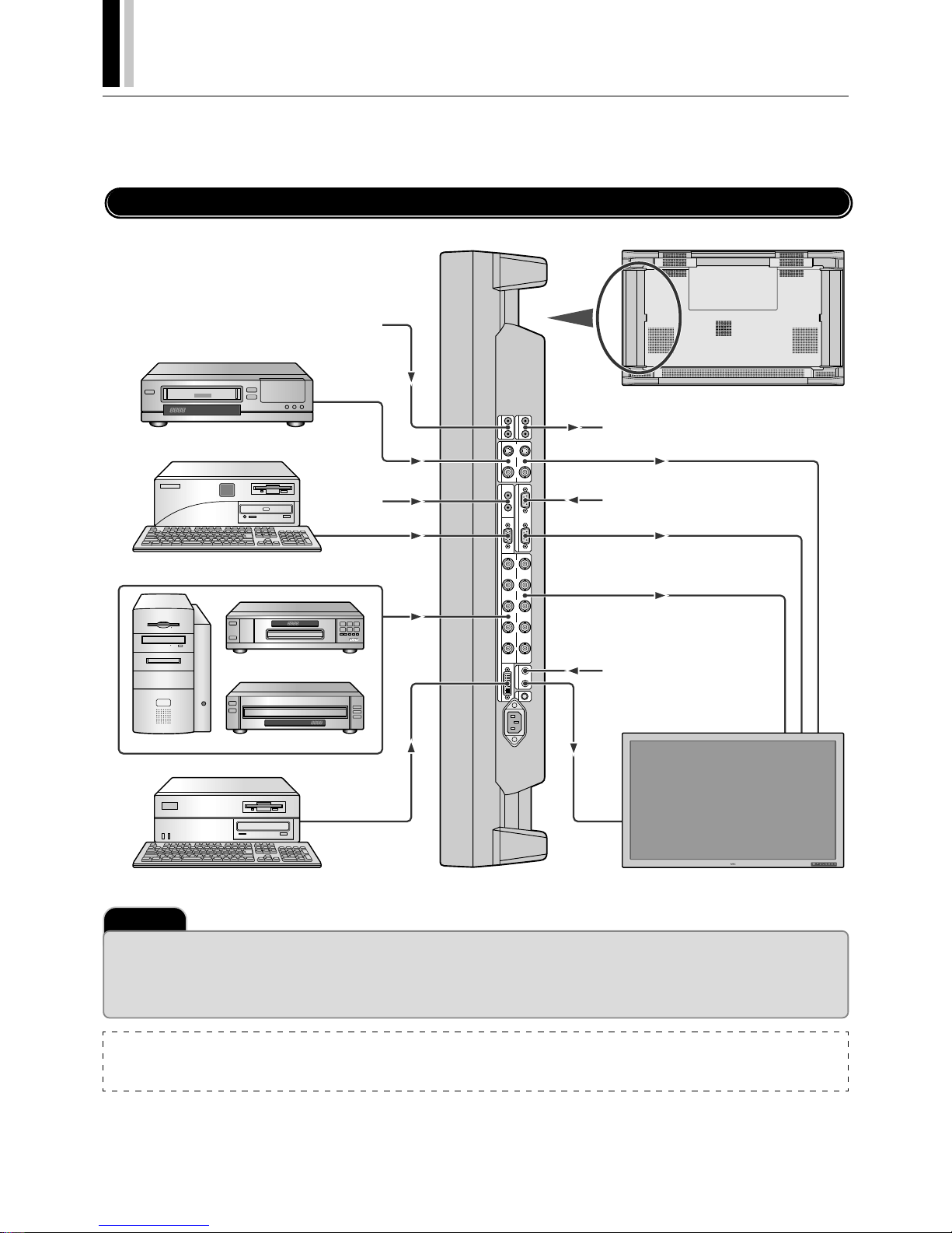
14
†
PLASMA MONITOR
Connections
Before making connections:
* First turn off the power of all the attached equipment and make connections.
* Refer to the user manual included with each equipment.
Wiring Diagram
AUDIO
OUT
LR
AUDIO
IN 2
L
(
MONO
)
R
VIDEO
OUT
S-VIDEO VIDEO
AUDIO IN 1
EXTERNAL CONTROL
RGB 1
L
(
MONO
)
RIN
IN OUT
IN
OUT
IN
RGB 2
/
DVD
/
HD
G
/
Y B
/
C
B
/
P
B
H
/
CS VR
/
C
R
/
P
R
REMOTE
RGB 3
AC IN
IN OUT
C
/
L
IN
Equipment with digital interface
Plasma monitor
Amplifier
External control equipment
Wired remote control (optional)
Plasma monitor (second monitor)
Audio signal of input device
VCR
Audio signal of
input device
Personal computer
DVD player
Personal computer
HD laser disk player
NOTE:
VIDEO connector
S-VIDEO IN connector will take preference over VIDEO IN connector when a component is connected to each connector.
Important
Four / Nine Multiple Screens System (VIDEO WALL MENU)
* Multiple System requires the optional Multiple Unit. Contact your dealer for more information.
* Use an optionally available BNC-typed signal cable that is within 1 to 2 m (3.3 to 6.6 feet) when one plasma monitor is connected to another one with the plasma
monitor 's OUT and IN connectors.
If image is degraded, use an optionally available distribution instead of using the OUT connector on the plasma monitor.
Page 16
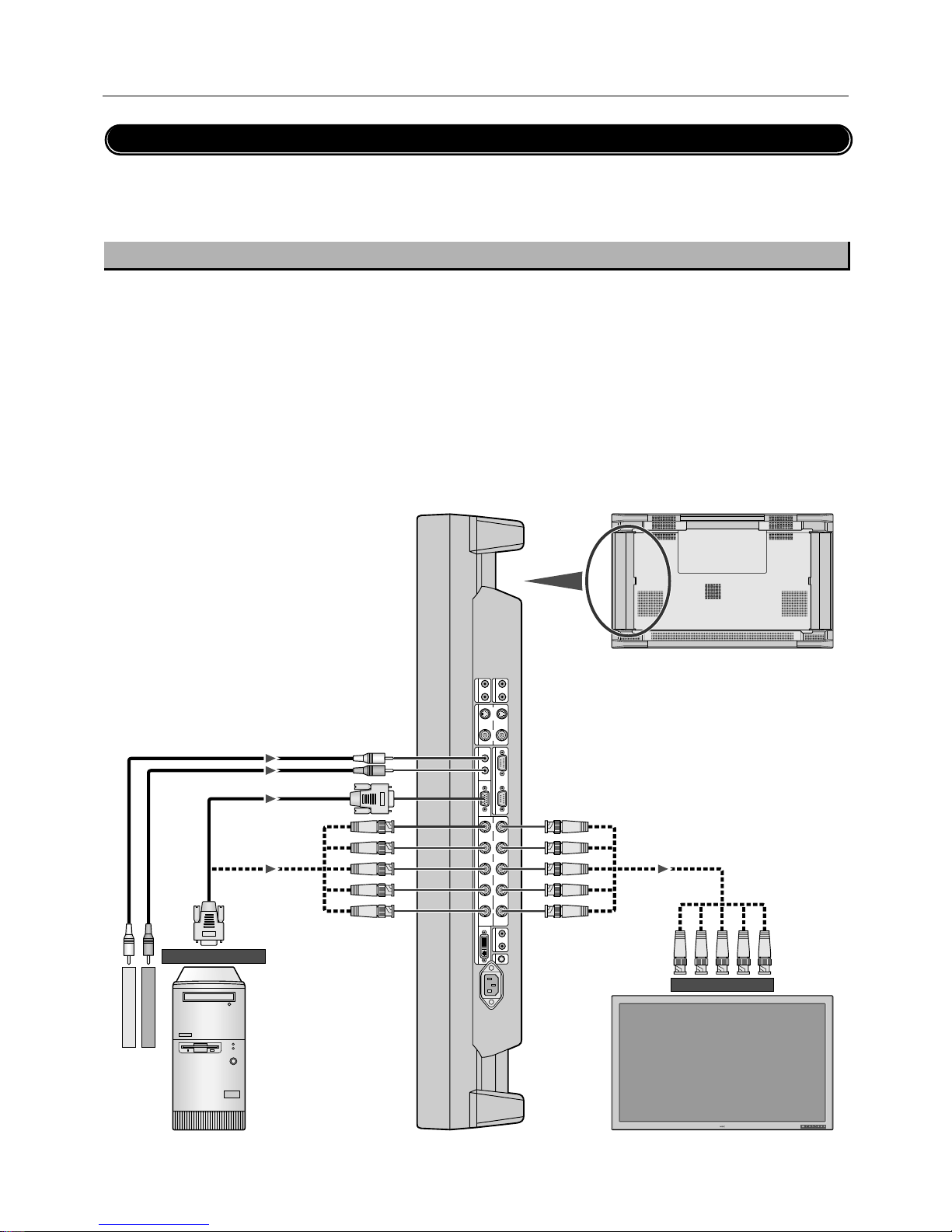
PLASMA MONITOR
† 15
Connecting Your PC or IBM compatible
Connecting your PC to your Plasma monitor will enable you to display your computer's screen image.
Some video cards may not display an image correctly.
If you wish to input wide signals, make the “RGB MODE” and “INPUT MODE” settings.
(See "Signal Identification For Raster Preset" on page 64.)
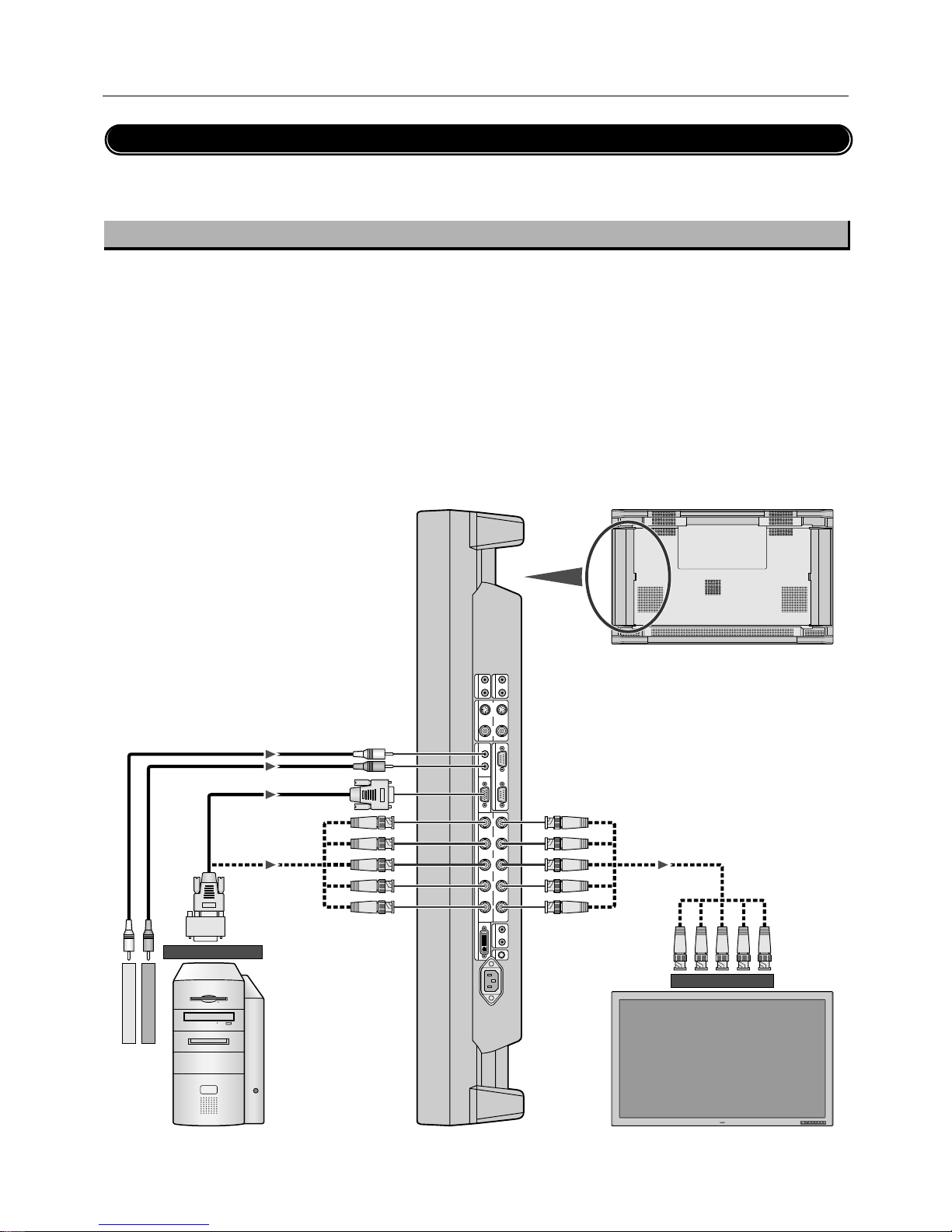
Connect the Plasma Monitor to Your PC or IBM Compatible
• To connect the RGB 1 IN connector (mini D-sub 15 pin) on the plasma monitor, use the supplied RGB signal cable (mini D-sub 15 pin to
mini D-sub 15 pin).
• To connect the RGB 2/DVD/HD IN connector (BNC) on the plasma monitor, use the optional signal cable (mini D-sub 15 pin to BNC x 5).
Select [RGB] for RGB 2 from the INPUT SELECT menu.
When connecting one or more Plasma monitors, use the RGB 2/DVD/HD OUT connector (BNC).
• The AUDIO IN 1 and 2 can be both used for audio input. For connection, select [INPUT 1] or [INPUT 2] from the SOUND menu.
Connections
AUDIO
OUT
LR
AUDIO
IN 2
L
(
MONO
)
R
VIDEO
OUT
S-VIDEO VIDEO
AUDIO IN 1
EXTERNAL CONTROL
RGB 1
L
(
MONO
)
RIN
IN OUT
IN
OUT
IN
RGB 2
/
DVD
/
HD
G
/
Y B
/
C
B
/
P
B
H
/
CS VR
/
C
R
/
P
R
REMOTE
RGB 3
AC IN
IN OUT
C
/
L
IN
Plasma monitor
Plasma monitor (second monitor)
To audio right output
To RGB 2/DVD/HD IN
BNC x 5
BNC x 5
RCA
Mini D-sub 15 pin
BNC x 5
Mini D-sub 15 pin
To analog RGB output
PC or IBM compatible
To audio left output
Page 17
16
†
PLASMA MONITOR
Connecting Your Macintosh Computer
Connecting your Macintosh computer to your Plasma monitor will enable you to display your
computer's screen image. Some video cards or drivers may not display images correctly. (See also "Signal Identification For Raster
Preset" on page 64.)
Connect the Plasma Monitor to Your Macintosh
• To connect the RGB 1 IN connector (mini D-sub 15 pin) on the plasma monitor, use the supplied RGB signal cable (mini D-sub 15 pin to
mini D-sub 15 pin).
For older Macintosh, use a pin adapter for Macintosh (available separately) to connect to your Macintosh's video port.
The resolution modes that you can select are:
• 13" fixed mode • 16" fixed mode • 19" fixed mode
• To connect the RGB 2/DVD/HD IN connector (BNC) on the plasma monitor, use the signal cable available separately (mini D-sub 15 pin
to BNC x 5).
Select [RGB] for [RGB 2] from the INPUT SELECT menu.
When connecting one or more Plasma monitors, use the RGB 2/DVD/HD OUT connector (BNC).
• If you use with a Macintosh PowerBook, set "Mirroring" to Off.
Refer to your Macintosh's owner's manual for more information about your computer's video output requirements and any special
identification or configuring your monitor's image and monitor may require.
• The AUDIO IN 1 and 2 (both RCA) can be both used for audio input. For connection, select [INPUT 1] or [INPUT 2] from the SOUND
menu.
AUDIO
OUT
LR
AUDIO
IN 2
L
(
MONO
)
R
VIDEO
OUT
S-VIDEO VIDEO
AUDIO IN 1
EXTERNAL CONTROL
RGB 1
L
(
MONO
)
RIN
IN OUT
IN
OUT
IN
RGB 2
/
DVD
/
HD
G
/
Y B
/
C
B
/
P
B
H
/
CS VR
/
C
R
/
P
R
REMOTE
RGB 3
AC IN
IN OUT
C
/
L
IN
Plasma monitor
Plasma monitor (second monitor)
To audio right output
To RGB 2/DVD/HD IN
BNC x 5
BNC x 5
RCA
Mini D-sub 15 pin
BNC x 5
Mini D-sub 15 pin
To video output port
Macintosh
To audio left output
Connections
Pin adapter for
Macintosh
Page 18
PLASMA MONITOR
† 17
Connections
Connections with Equipment that has a Digital Interface
Connections can be made with equipment that is equipped with a digital interface compliant with the DVI (Digital Visual Interface) standard.
If you wish to input wide signals, make the “RGB MODE” and “INPUT MODE” settings.
(See “Signal Identification For Raster Preset” on page 64.)
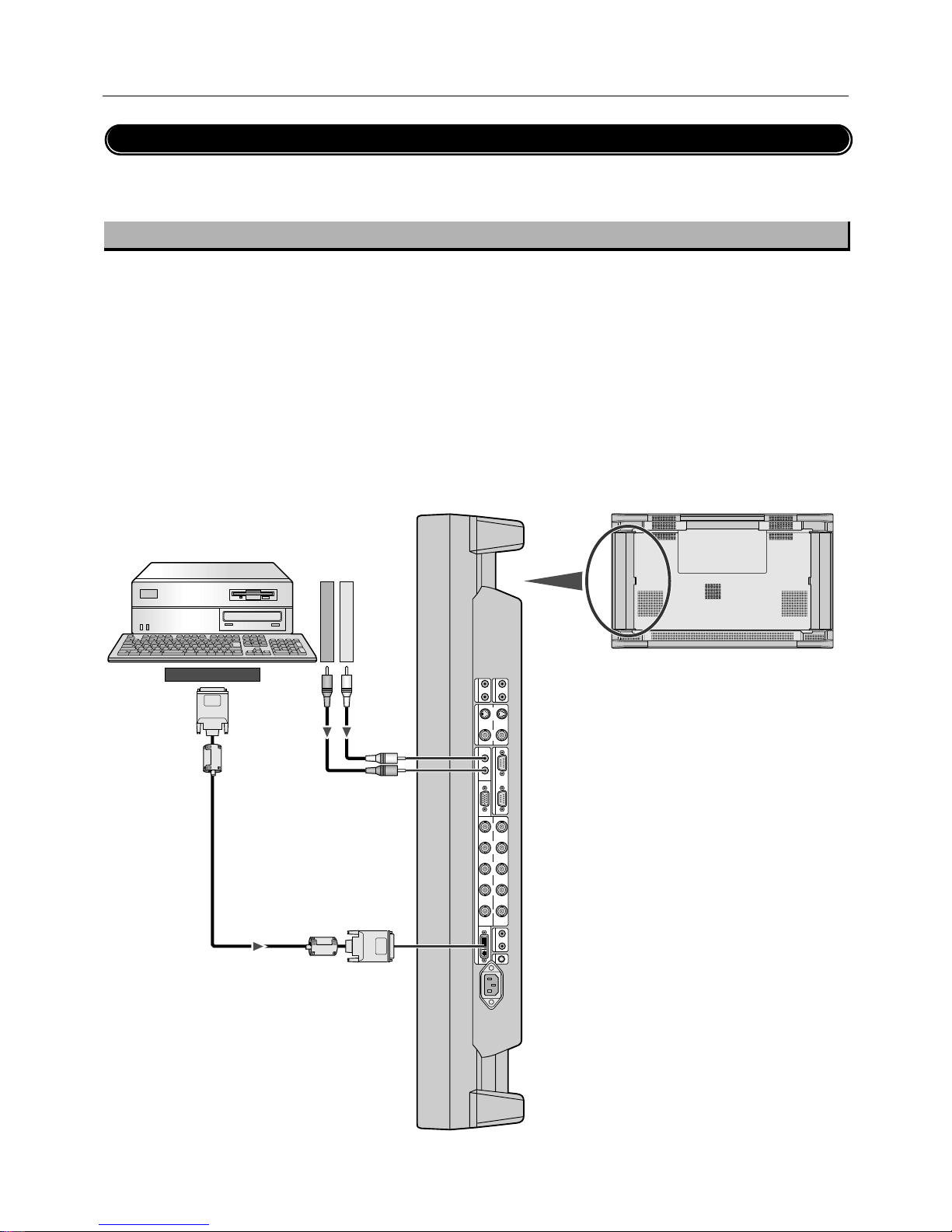
Connect the Plasma Monitor to a Computer with a Digital Output
• To connect the RGB 3 IN connector on the plasma monitor, use a DVI 29-pin signal cable (available separately).
• The RGB 3 IN connector also accepts a DVI 25-pin (digital only) cable.
• Input TMDS signals conforming to DVI standards.
• To maintain display quality, use a cable with a quality prescribed by DVI standards that is within 5 meters (6.6 feet) in length.
• Attach the supplied small ferrite cores to the DVI signal cable. See page 50 for attaching the ferrite cores.
• The AUDIO IN 1 and 2 (both RCA) can be both used for audio input. For connection, select [INPUT 1] or [INPUT 2] from the SOUND
menu.
AUDIO
OUT
LR
AUDIO
IN 2
L
(
MONO
)
R
VIDEO
OUT
S-VIDEO VIDEO
AUDIO IN 1
EXTERNAL CONTROL
RGB 1
L
(
MONO
)
RIN
IN OUT
IN
OUT
IN
RGB 2
/
DVD
/
HD
G
/
Y B
/
C
B
/
P
B
H
/
CS VR
/
C
R
/
P
R
REMOTE
RGB 3
AC IN
IN OUT
C
/
L
IN
To audio right output
To audio left output
Plasma monitor
RCA
RCA
DVI connector
Ferrite core
Ferrite core
DVI connector
To digital RGB output
Equipment with a digital interface such as a
personal computer with RGB output (TMDS)
Page 19
18
†
PLASMA MONITOR
AUDIO
OUT
LR
AUDIO
IN 2
L
(
MONO
)
R
VIDEO
OUT
S-VIDEO VIDEO
AUDIO IN 1
EXTERNAL CONTROL
RGB 1
L
(
MONO
)
RIN
IN OUT
IN
OUT
IN
RGB 2
/
DVD
/
HD
G
/
Y B
/
C
B
/
P
B
H
/
CS VR
/
C
R
/
P
R
REMOTE
RGB 3
AC IN
IN OUT
C
/
L
IN
Connections
Connecting Your VCR
Connecting your VCR or laser disc player to your Plasma monitor will enable you to display your VCR' s or laser disc player' s video.
Refer to your VCR or laser disc player owner's manual for more information.
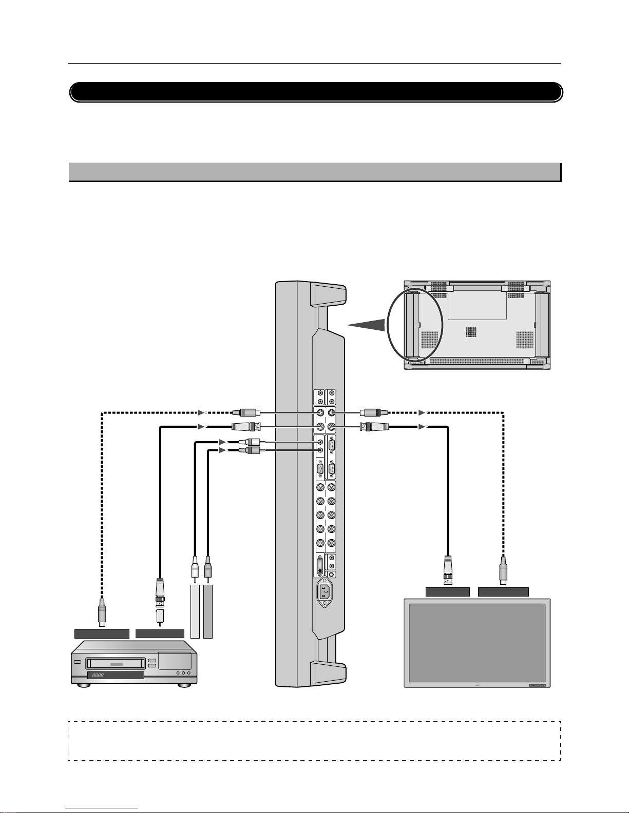
Connect the Plasma Monitor to a VCR or Laser Disc Player
• To connect the VIDEO IN connector (BNC) on the plasma monitor, use a separately available BNC connector cable. You will need a
separately available BNC-to-RCA adapter to connect a VCR or laser disc player with an RCA pin jack to the BNC connector cable.
• When connecting one or more Plasma monitors, use the VIDEO OUT connectors (BNC).
• The AUDIO IN 1 and 2 (both RCA) can be both used for audio input. For connection, select [INPUT 1] or [INPUT 2] from the SOUND
menu.
To audio right output
To audio left output
Plasma monitor
RCA
Plasma monitor (second monitor)
DIN 4 pin
BNC
BNC
DIN 4 pin
To VIDEO IN To S-VIDEO IN
BNC
DIN 4 pin
BNC
DIN 4
pin
To VIDEO OUT
To S-VIDEO OUT
BNC-to-RCA
adapter
VCR or Laser disc player
NOTE:
VIDEO connector
S-VIDEO IN will take precedence over VIDEO IN when a component is connected to each connector.
Page 20
PLASMA MONITOR
† 19
Connections
Connecting Your DVD Player
Connecting your DVD player to your Plasma monitor will enable you to display your DVD' s video.
Refer to your DVD player owner's manual for more information.
* When a video filmed in frames per second (progressive) is played back, the plasma monitor takes the second and third frames, and
converts them into a progressive signal with 60 frames per second. Note that only NTSC and 480i at 60 Hz is available.
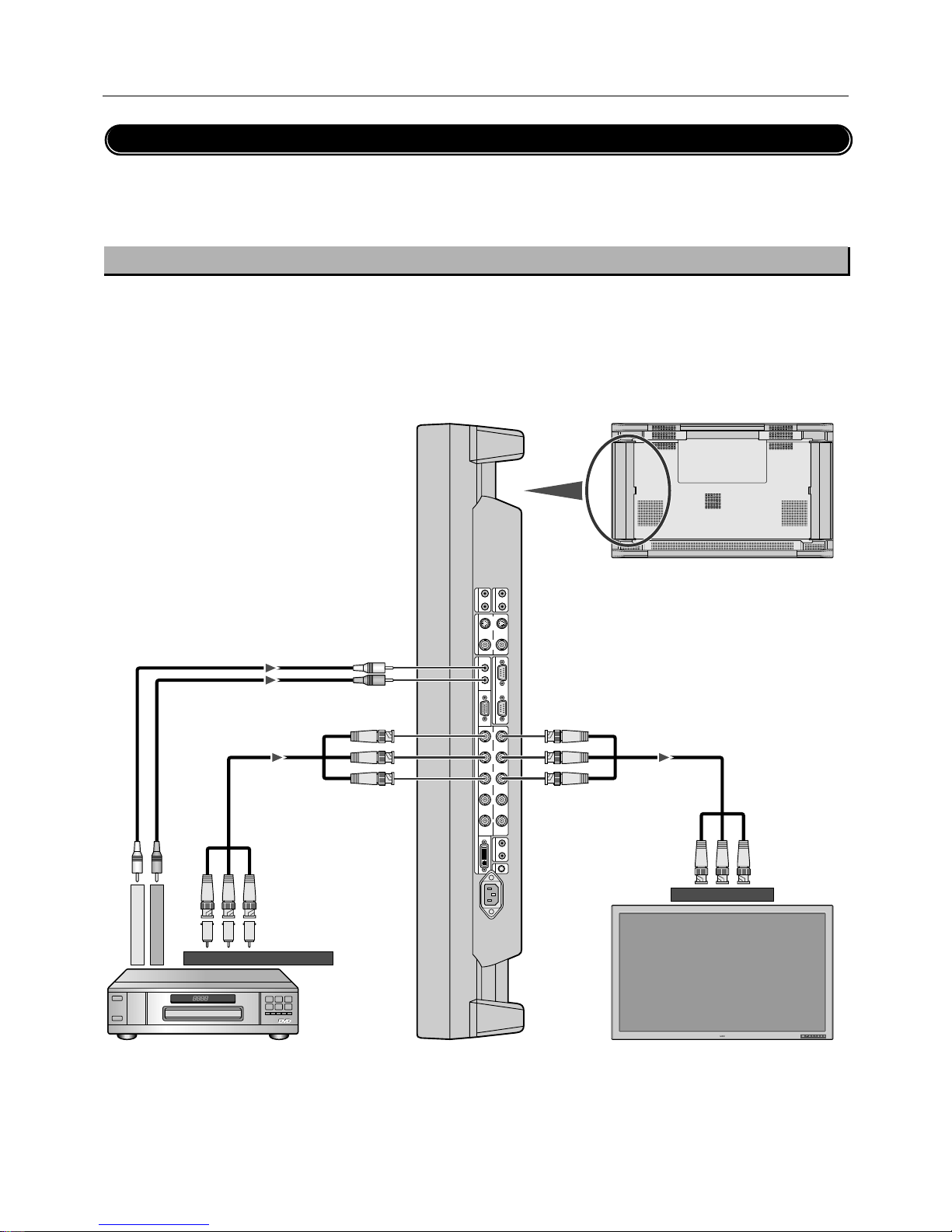
Connect the Plasma Monitor to a DVD Player
• To connect the RGB 2/DVD/HD IN connector (BNC) on the plasma monitor, use a separately available BNC connector cable. You will
need a separately available BNC-to-RCA adapter to connect a DVD player with an RCA pin jack to the BNC connector cable.
Some DVD players may have different connectors such as Y,Cb/Pb, and Cr/Pr.
Select [DVD/HD] for RGB 2 from the INPUT SELECT menu.
When connecting one or more Plasma monitors, use the RGB 2/DVD/HD OUT connectors (BNC).
• The AUDIO IN 1 and 2 (both RCA) can be both used for audio input. For connection, select [INPUT 1] or [INPUT 2] from the SOUND
menu.
AUDIO
OUT
LR
AUDIO
IN 2
L
(
MONO
)
R
VIDEO
OUT
S-VIDEO VIDEO
AUDIO IN 1
EXTERNAL CONTROL
RGB 1
L
(
MONO
)
RIN
IN OUT
IN
OUT
IN
RGB 2
/
DVD
/
HD
G
/
Y B
/
C
B
/
P
B
H
/
CS VR
/
C
R
/
P
R
REMOTE
RGB 3
AC IN
IN OUT
C
/
L
IN
Plasma monitor
Plasma monitor (second monitor)
BNC X3
BNC X3
BNC X3
RCA
BNC X3
BNC-to-RCA adapter
To audio right output
To audio left output
To DVD Component video output
To RGB 2/DVD/HD IN
DVD player
Page 21
20
†
PLASMA MONITOR
AUDIO
OUT
LR
AUDIO
IN 2
L
(
MONO
)
R
VIDEO
OUT
S-VIDEO VIDEO
AUDIO IN 1
EXTERNAL CONTROL
RGB 1
L
(
MONO
)
RIN
IN OUT
IN
OUT
IN
RGB 2
/
DVD
/
HD
G
/
Y B
/
C
B
/
P
B
H
/
CS VR
/
C
R
/
P
R
REMOTE
RGB 3
AC IN
IN OUT
C
/
L
IN
Connections
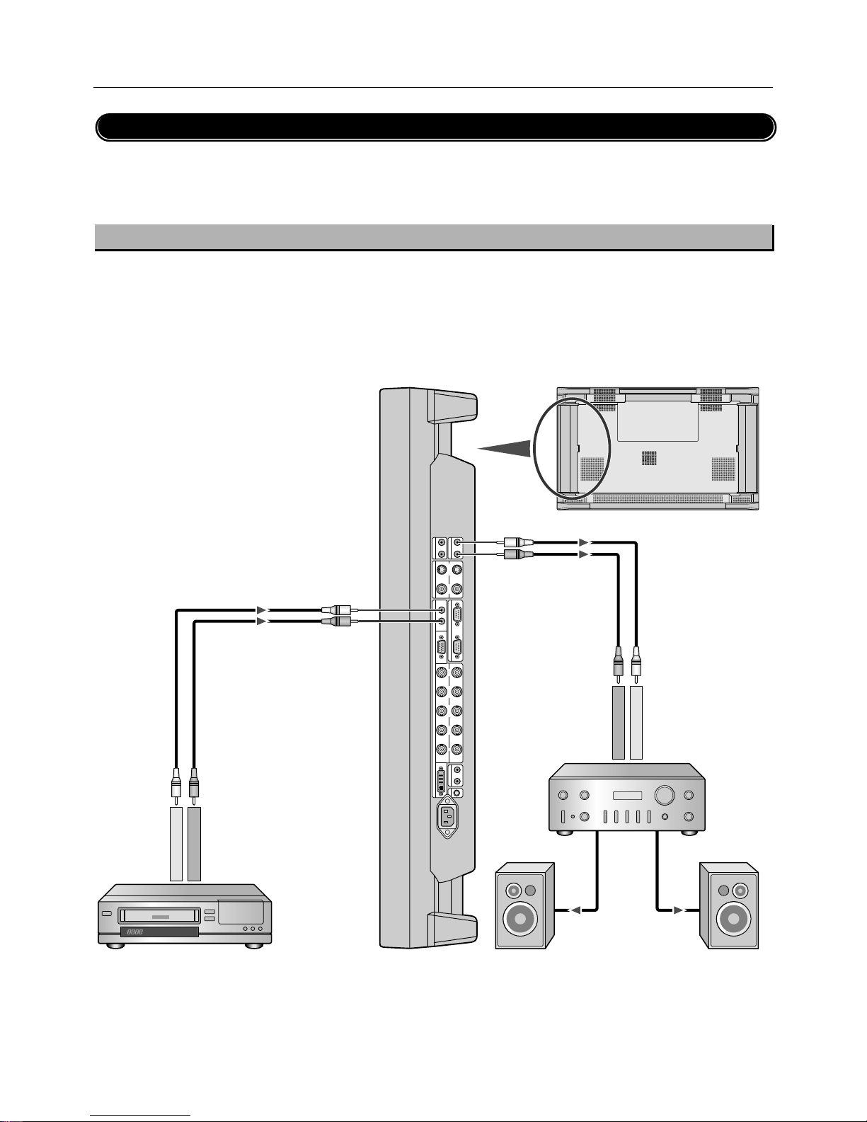
Connecting Your Stereo Amplifier
You can connect your stereo amplifier to your Plasma monitor. Refer to your amplifier owner's manual for more information.
Connect the Plasma Monitor to a Stereo Amplifier
• Turn on the plasma monitor and the amplifier only after all hookups have been made.
• Use an RCA cable to connect the AUDIO OUT connector (RCA) on the plasma monitor and the audio input on the amplifier.
• Do not reverse the audio left and right jacks.
• The AUDIO IN 1 and 2 (both RCA) can be both used for audio input. For connection, select [INPUT 1] or [INPUT 2] from the SOUND
menu.
• The AUDIO OUT jack outputs sound for the currently selected video.
To audio right input
To audio left input
Plasma monitor
RCA
Amplifier
VCR or Laser disc player
To audio right output
To audio left output
RCA
RCA
RCA
External speaker
External speaker
Page 22
PLASMA MONITOR
† 21
Basic Operation
Before operating the remote control, be sure to turn on the main power to the plasma monitor.
EXITPROCEEDDOWNUPRGBVIDEO
POWER/STANDBY
POWER OFF
RGB 1
POWER ON
RGB 3
RGB 2/DVD/HD
VI DEO
EXI T
PROCEED
POSITION/CONTROL
RP-102
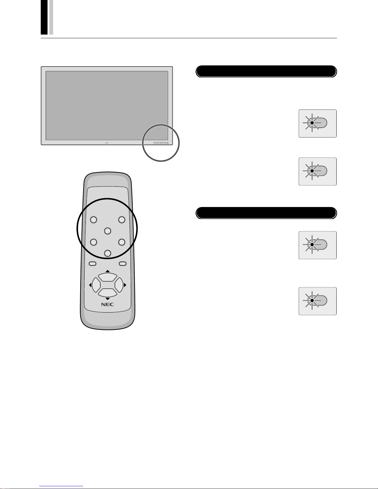
Turning on the Main Power and Return to Standby Mode
The plasma monitor enters the standby mode and the POWER/
STANDBY lamp is lit in orange when the power cable is plugged
into the wall outlet.
POWER/STANDBY
To turn the main power:
Press the POWER button on the front
panel of the plasma monitor
The main power will be turned on.
The POWER/STANDBY lamp is lit in green.
To turn off the power
(standby mode):
Press the POWER button again
The plasma monitor is in standby mode.
The POWER/STANDBY lamp is lit in orange.
POWER/STANDBY
Turning On or Off the Power with the Remote Control
POWER/STANDBY
To turn on the plasma monitor:
Make sure that the POWER/STANDBY
lamp is lit in orange (standby).
Press the POWER ON button on the remote control.
The plasma monitor is turned on.
The POWER/STANDBY lamp is lit in green.
To turn off the plasma monitor:
Press the POWER OFF button on the
remote control.
The plasma monitor enters the standby
mode.
The POWER/STANDBY lamp is lit in orange.
POWER/STANDBY
* The standby mode used here is the condition that exists when
the power management is on. This is not the standby mode set
by the remote control's powering-off.
Page 23

Page 24

Page 25

Page 26

Page 27

Page 28

Page 29

Page 30

Page 31

Page 32
PLASMA MONITOR
† 31
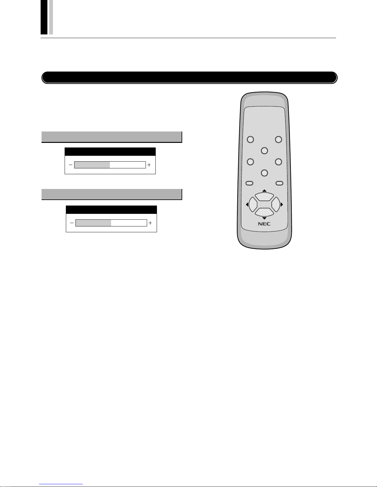
Horizontal/Vertical Position Adjustments (H-POSITION and V-POSITION)
Horizontal and vertical position adjustments are available in 2 types. “Direct adjustment” makes adjustments simply by pressing the
buttons of the remote control and “Menu control adjustments” are made via menu display.
Direct Adjustment
Adjusts the horizontal position and the vertical position of the
screen.
A press of the button displays the adjustment screen. Release
your finger from the button after the adjustment is made. The display will disappear about 3 seconds later and the adjustment details will be stored.
Move left Move right
▼ Move down Move up ▲
Vertical position adjustment (POSITION/CONTROL
▲▼
)
Horizontal position adjustment (POSITION/CONTROL
)
POWER OFF
RGB 1
POWER ON
RGB 3
RGB 2/DVD/HD
VI DEO
EXI T
PROCEED
POSITION/CONTROL
RP-102
H-POSITION
V-POSITION
Page 33

Page 34

Page 35

Page 36

Page 37

Page 38

Page 39

Page 40

Page 41
40
†
PLASMA MONITOR
4
2
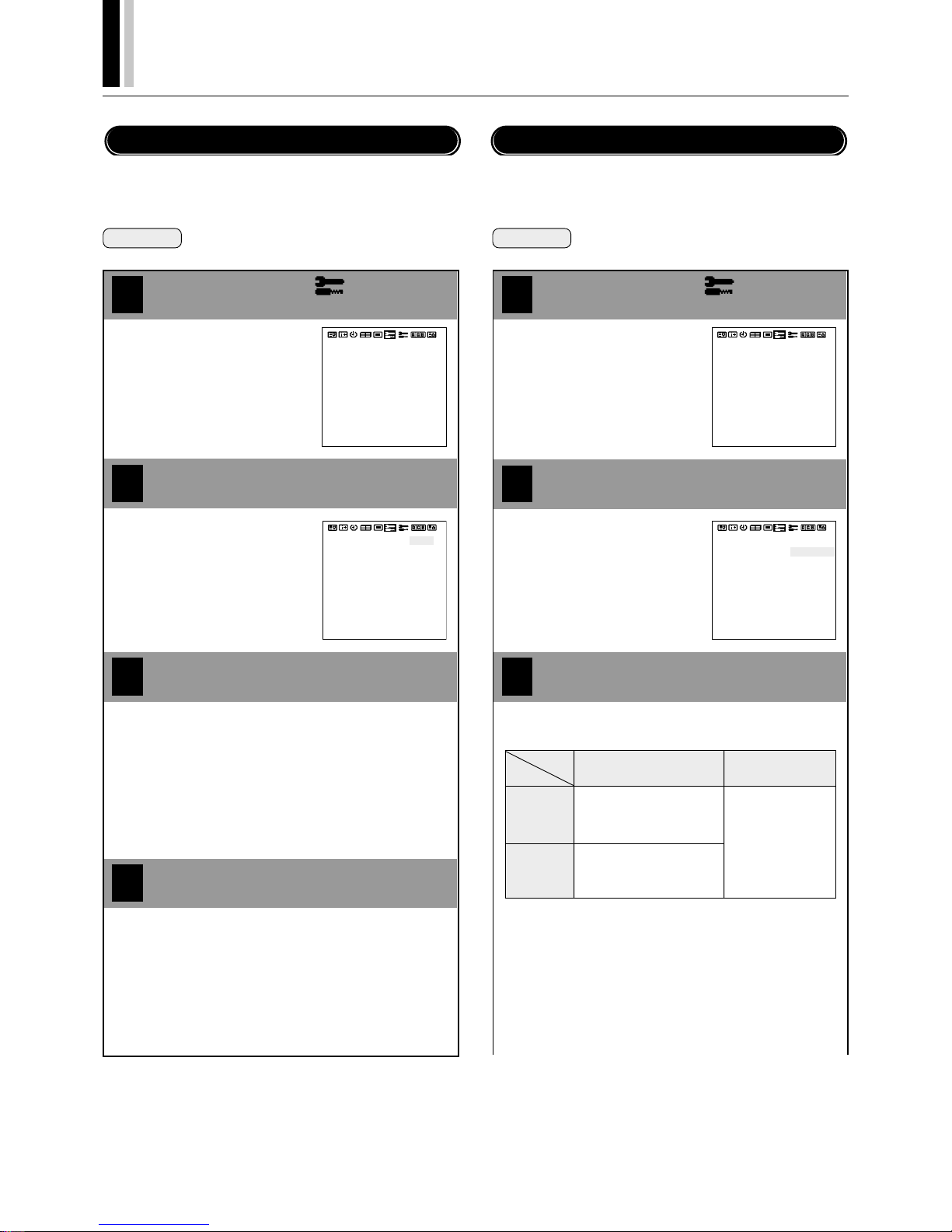
Other Functions (OTHER SETTINGS)
This function sets the color system (to AUTO, 3.58 NTSC, PAL,
SECAM, or 4.43 NTSC).
Set [OSD MODE] to [PRO] on the configuration menu, then perform the following operations.
Preparation Press the PROCEED button to display the main
menu.
1
Align the cursor with
3
Move the cursor left and right with
the POSITION/CONTROL
buttons.
COLOR SYSTEM
P-ON MODE
POWER MANAGER
SET ID NO
RGB3 ADJUST
CINEMA MODE
ALL RESET
: AUTO
: OFF
: ALL
: 1
: ON
: LAST MEM
COLOR SYSTEM
P-ON MODE
POWER MANAGER
SET ID NO
RGB3 ADJUST
CINEMA MODE
ALL RESET
: AUTO
: OFF
: ALL
: 1
: ON
: LAST MEM
Align the cursor with COLOR SYSTEM
Set the color system with the POSITION/
CONTROL
buttons
Move the cursor up and down with
the POSITION/CONTROL ▲▼
buttons.
Press the EXIT button 2 times
Press the EXIT button one time to return to the main menu.
One further press removes the menu.
* Aligning the cursor with [ALL RESET] and pressing the
PROCEED button will return all the settings of the other
functions to the default settings.
Color System Settings (COLOR SYSTEM)
[AUTO] : Automatically detects the color system and
selects it.
[3.58 NTSC]
: Standard system for mainly North America and
Japan.
[PAL] :
Standard system for mainly the UK and Germany.
[SECAM] : Standard system for mainly France and Russia.
[4.43 NTSC]
: System mainly used in VTRs in PAL/SECAM
regions.
Preparation Press the PROCEED button to display the main
menu.
1
2
3
Move the cursor left and right with
the POSITION/CONTROL
buttons.
COLOR SYSTEM
P-ON MODE
POWER MANAGER
SET ID NO
RGB3 ADJUST
CINEMA MODE
ALL RESET
: AUTO
: OFF
: ALL
: 1
: ON
: LAST MEM
: AUTO
: OFF
: ALL
: 1
: ON
COLOR SYSTEM
P-ON MODE
POWER MANAGER
SET ID NO
RGB3 ADJUST
CINEMA MODE
ALL RESET
: LAST MEM
Align the cursor with P-ON MODE
Set the P-ON MODE with the POSITION/
CONTROL
buttons
Move the cursor up and down with
the POSITION/CONTROL ▲▼
buttons.
Power-On Mode Setting (P-ON MODE)
The mode that is displayed will be as indicated below according to the setting of [Input Selection].
[LAST MEM] : This is the input mode that was last selected
(at the time the power was switched off).
(Last Memory)
[VIDEO] : This results in the VIDEO input mode.
[RGB 1] : This results in the RGB 1 input mode.
[RGB 2] : This results in the RGB 2 input mode.
[RGB 3] : This results in the RGB 3 input mode.
[DVD/HD] : This results in the DVD/HD input mode.
[SCART] : This results in the SCART jack input mode.
RGB 2
RGB
DVD/HD
SCART
OFF
LAST MEM, VIDEO,
RGB 1, RGB 2,
RGB 3
LAST MEM, VIDEO
RGB 1, HD/DVD,
RGB 3
ON
LAST MEM
VIDEO, RGB 1,
SCART,
RGB 3
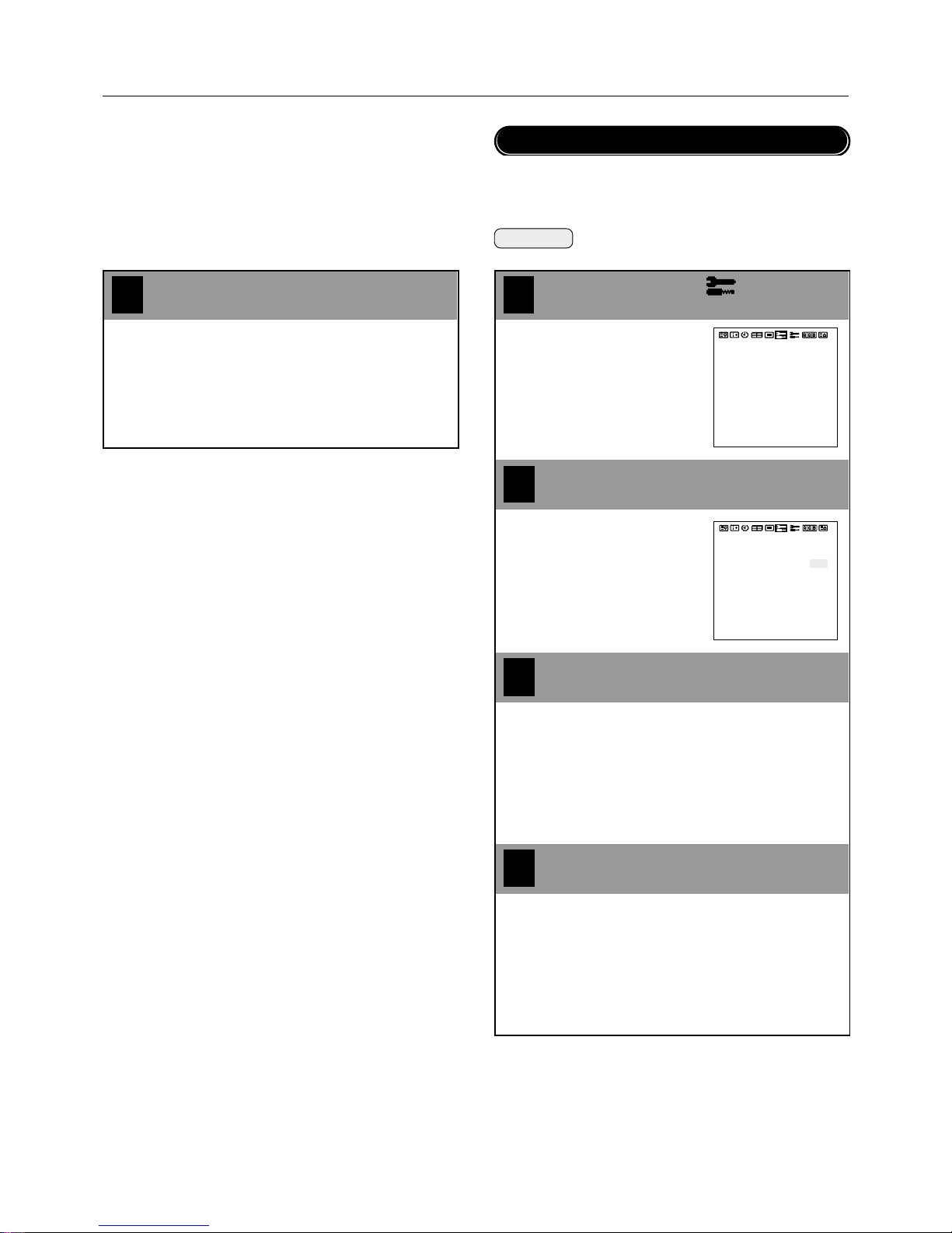
Align the cursor with
This function sets the input mode at the time the power is switched
on.
Set [OSD MODE] to [PRO] on the configuration menu, then perform the following operations.
Page 42
PLASMA MONITOR
† 41
Other Functions (OTHER SETTINGS)
4
1
Align the cursor with
2
3
Move the cursor left and right with
the POSITION/CONTROL
buttons.
COLOR SYSTEM
P-ON MODE
POWER MANAGER
SET ID NO
RGB3 ADJUST
CINEMA MODE
ALL RESET
: AUTO
: OFF
: ALL
: 1
: ON
: LAST MEM
: AUTO
: OFF
: ALL
: 1
: ON
COLOR SYSTEM
P-ON MODE
POWER MANAGER
SET ID NO
RGB3 ADJUST
CINEMA MODE
ALL RESET
: LAST MEM
Set the power management mode with
the POSITION/CONTROL
buttons
Move the cursor up and down with
the POSITION/CONTROL ▲▼
buttons.
Press the EXIT button 2 times
Press the EXIT button one time to return to the main menu.
One further press removes the menu.
* Aligning the cursor with [ALL RESET] and pressing the PRO-
CEED button will return all the settings of the other functions
to the default settings.
This sets the functions that serve to automatically reduce power
consumption.
Set [OSD MODE] to [PRO] on the configuration menu, then perform the following operations.
Power Management Settings (POWER MANAGER)
Align the cursor with POWER MAN-
AGER
[ON] : Power management function operates.
[OFF] : Power management is cancelled.
Preparation Press the PROCEED button to display the main
menu.
4
Press the EXIT button one time to return to the main menu.
One further press removes the menu.
* Aligning the cursor with [ALL RESET] and pressing the PRO-
CEED button will return all the settings of the other functions
to the default settings.
Press the EXIT button 2 times
Page 43

Page 44

Page 45

Page 46

Page 47

Page 48

Page 49

Page 50

Page 51

Page 52
PLASMA MONITOR
† 51
Pin No. Signal (Analog)
1Red
2 Green or sync-on-green
3 Blue
4 Ground
5 Ground
6 Red ground
7 Green ground
8 Blue ground
9 No connection
10 Sync signal ground
11 Ground
12 Bi-directional DATA (SDA)
13 Horizontal or composite sync
14 Vertical sync
15 Data clock
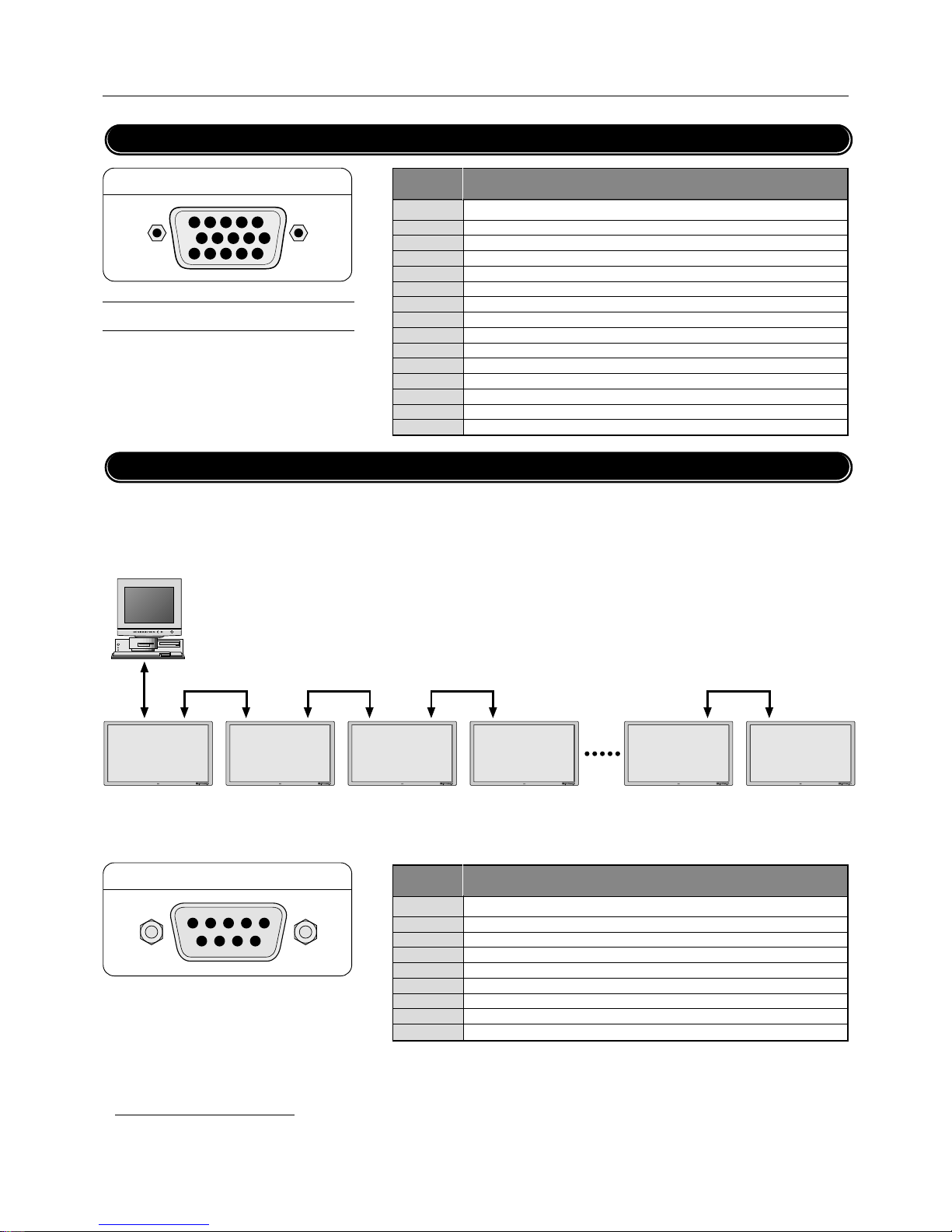
Pin Configuration and Signal Level of Mini D-Sub 15-Pin (Analog) Input Connector
Appendix
RGB1
1
2
3
4
5
6
7
8
9
10
11
121314
15
Pin No. Function
1 No connection
2 RXD (Receive data)
3 TXD (Transmit data)
4 No connection
5 Ground
6 No connection
7 RTS (Ready to send)
8 CTS (Clear to send)
9 No connection
EXTERNAL CONTROL
45321
6789
Signal level
VIDEO signal : 0.7Vp-p (Analog)
Sync signal : TTL level
Pin Configuration and Functions of External Control Connector (Mini D-Sub 9 -Pin)
Application
These specifications are applicable to NEC plasma monitors (including 42- and 50-inch types) and communications control from
external equipment.
Connections
Connections should be made as described below.
1)Display-side connector: EXTERNAL CONTROL connector
2)External equipment side connector: Serial port (RS-232C) connector
See the specifications of the connected equipment for information about the type of connector and pin assignment.
3)Wiring
Use a crossed (reverse) cable.
Wire the cable so that each pair of data lines cross between the two devices. These data line pairs are RXD (Receive data) and
TXD (Transmit data), DTR (DTE side ready) and DSR (DCE side ready), and RTS (Ready to send) and CTS (Clear to send).
*A maximum of 4 units can used with a cascade connection.
External equipment
e.g., Personal computer
PDP1 Display
PDP4 Display
PDP3 DisplayPDP2 Display PDP8 Display PDP9 Display
Page 53

Page 54

Page 55

Page 56

Page 57

Page 58

Page 59

Page 60

Page 61

Page 62

PLASMA MONITOR
† 61
Appendix
41. MULTI MODE Request
Function
The master monitor requests the status of
MULTI MODE of the slave for master.
Transmission data
0FH UA1 UA2 3BH 00H CKS
ACK
6FH UA1 UA2 3BH 02H DATA–02 CKS
DATA00 : SCREEN DIVIDER SETTING
01H : Single mode
02H : 03H : Multi mode 4 screens
04H : Multi mode 9 screens
DATA01 : POSITION OF DIVIDE
NOTE: When DATA00 is 01H, this data is invalid.
01H : Upper left selected (4 screens)
02H : Upper right selected (4 screens)
03H : Lower right selected (4 screens)
04H : Lower left selected (4 screens)
05H : 06H : 07H : Top left selected (9 screens)
08H : Top middle selected (9 screens)
09H : Top right selected (9 screens)
0AH : Middle left selected (9 screens)
0BH : Middle center selected (9 screens)
0CH : Middle right selected (9 screens)
0DH : Bottom left selected (9 screens)
0EH : Bottom middle selected (9 screens)
0FH : Bottom right selected (9 screens)
42. OSM Select
Function
The external equipment switches the on-screen
menu (OSM) of the display unit ON and OFF.
Transmission Data
DFH 80H 60H 58H 01H DATA00 CKS
DATA00
01H : OSM ON (During normal operation)
02H : OSM OFF
ACK
7FH 60H 80H 58H 01H DATA00 CKS
DATA00
01H : OSM ON
02H : OSM OFF
* Use this command with the setting of bits 0
and 1 fixed as follows: bit 0 = 1, and bit 1 = 1.
* ACK should be ignored in the case of a cas-
cade connection.
43. VOLUME Gain Data
Function
The master monitor changes the volume gain
data of the slave.
Transmission data
CFH UA1 UA2 21H 03H DATA00–02 CKS
DATA00 : VOLUME Gain
00H : 0
|
18H : 24
DATA01 : BALANCE Gain
E8H : -24
|
00H : 0
|
18H : +24
DATA02 : MUTE
00H : OFF
01H : ON
ACK
6FH UA1 UA2 21H 03H DATA00–02 CKS
DATA00 : VOLUME Gain
DATA01 : BALANCE Gain
DATA02 : MUTE
44. SOUND INPUT Select
Function
The master monitor changes the audio input of
the slave.
Transmission data
CFH UA1 UA2 05H 02H DATA00–01 CKS
DATA00 : INPUT1
00H : VIDEO
01H : RGB1
02H : RGB2, DVD/HD, SCART
03H : RGB3
DATA01 : INPUT2
00H : VIDEO
01H : RGB1
02H : RGB2, DVD/HD, SCART
03H : RGB3
ACK
6FH UA1 UA2 05H 02H DATA00–01 CKS
DATA00 : INPUT1
DATA01 : INPUT2
45. VOLUME Gain Data Request
Function
The master monitor changes the VOLUME gain
data of the slave.
Transmission data
0FH UA1 UA2 46H 00H CKS
ACK
DATA00 : VOLUME Gain
00H : 0
|
18H : 24
DATA01 : BALANCE Gain
E8H : -24
|
00H : 0
|
18H : +24
DATA02 : MUTE
00H : OFF
01H : ON
46. SOUND INPUT SELECT Request
Function
The master monitor requests the status of the
audio input of the slave.
Transmission data
0FH UA1 UA2 60H 00H CKS
ACK
6FH UA1 UA2 60H 02H DATA00–01 CKS
DATA00 : INPUT1
00H : VIDEO
01H : RGB1
02H : RGB2, DVD/HD, SCART
03H : RGB3
DATA01 : INPUT2
00H : VIDEO
01H : RGB1
02H : RGB2, DVD/HD, SCART
03H : RGB3
Page 63

Page 64

Page 65

Page 66

Page 67

Page 68
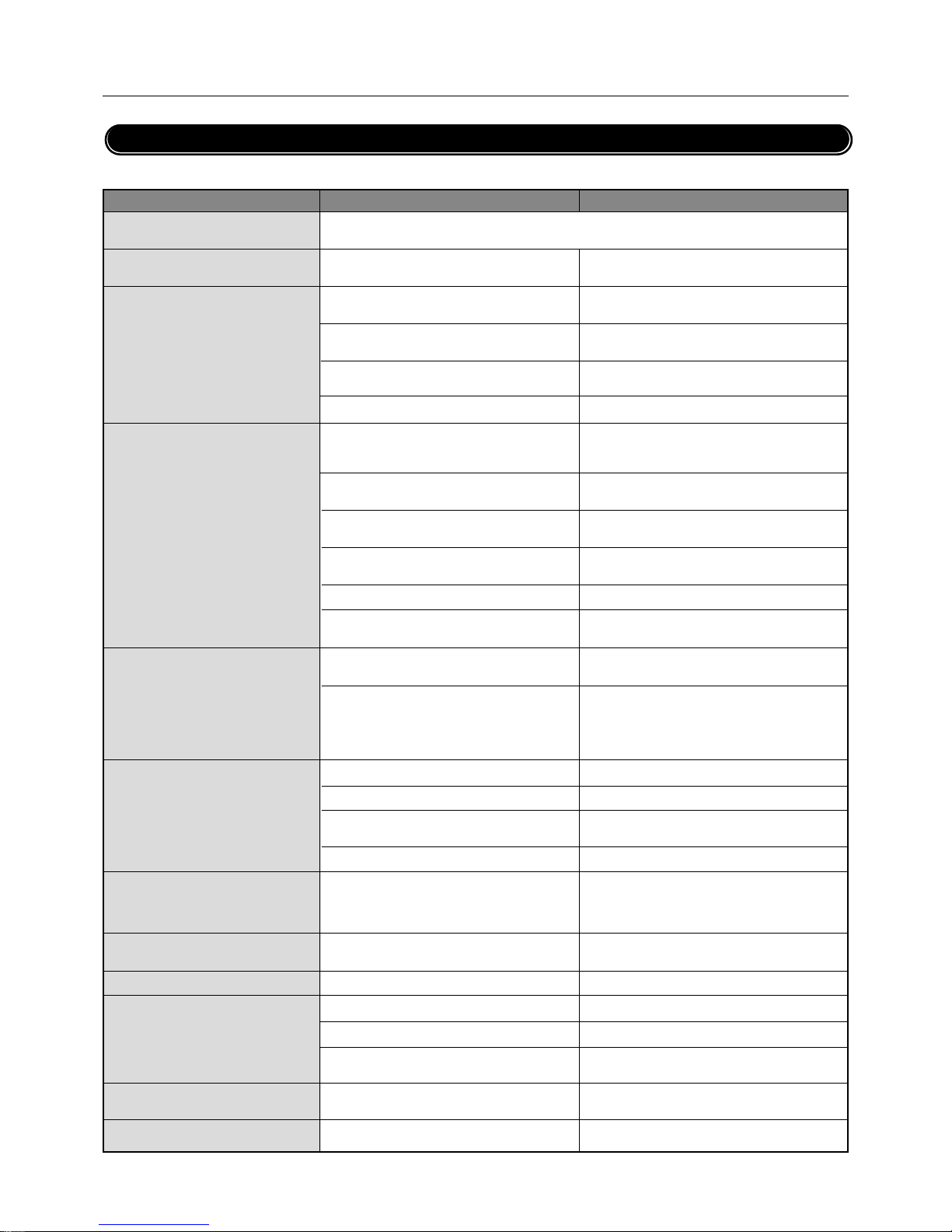
PLASMA MONITOR
† 67
Appendix
If the picture quality is poor or there is some other problem, check the adjustments, operations, etc., before requesting service.
Symptom Checks
Remedy
Troubleshooting
• Is a connected component set directly in front
or at the side of the display?
• Is the monitor’s power cord plugged into a
power outlet?
• Are all the monitor’s indicators off?
• Has an ID number been set for the main unit?
• Are the remote control’s batteries worn out?
• Is the remote control pointed at the monitor,
or is there an obstacle between the remote
control and the monitor?
• Is direct sunlight or strong artificial light shining on the monitor’s remote control sensor?
• You are not within the effective operating
range.(Wireless)
• Has an ID number been set for the main unit?
• Are the remote control's batteries worn out?
• The front panel buttons of the main unit do
not function
• Is the monitor's power cord plugged into a
power outlet?
• Power outlet inactive.
Power of external equipment is not ON.
External equipment has been incorrecty connected.
Incorrect input selection.
• Is the volume set at the minimum?
• Is the mute mode set on?
• Are the amplifier, speakers properly con-
nected?
• Is AUDIO INPUT set correctly?
• Improper control setting.
Local interference.
Cable interconnections.
Input impedance is not correct level.
• Improper control setting.
Incorrect 15 PIN connector pin connections.
• Are the tint and colors properly adjusted?
• Is the computer's power turned on?
• Is a source connected?
• Is the power manager function in the standby
or off mode?
• Is the position adjustment appropriate?
• Is the screen size adjustment appropriate?
• Leave some space between the display and the
connected components.
• Plug the monitor’s power cord into a power outlet.
• Plug the monitor’s power cord into a power outlet.
• Set an ID number with the ID SELECT button,
or set the ID number to ALL.
• Replace both batteries with new ones.
• Point the remote control at the monitor’s remote
control sensor when pressing buttons, or remove
the obstacle.
• Eliminate the light by closing curtains, pointing
the light in a different direction, etc.
• Use the remote control within 30º left and right
of center (at a diatance of 22ft).
• Set an ID number with the ID SELECT button,
or set the ID number to ALL.
• Replace both batteries with new ones.
• The front panel buttons do not function during
Control Lock
• Plug the monitor's power cord into a power outlet.
• Be sure wall switch is on and outlet has power.
Switch to ON or connect to an active AC outlet.
Correct all connections.
Press correct RGB1, RGB2/DVD/HD, RGB3, or
VIDEO button.
• Increase the volume on the sound menu.
• Set MUTE OFF on the SOUND menu.
• Connect the amplifier, speakers properly.
• Set INPUT on the SOUND menu correctly.
• Adjust picture controls as needed.
Try another location for the monitor.
Be sure all connections are secure.
• Adjust picture controls as needed.
Check pin assignments and connections.
• Adjust the tint and color.
• Turn on the computer's power.
• Connect source to the monitor.
• Operate the computer (move the mouse. etc.)
• Adjust the “AUTO PICTURE” properly.
• Make the adjustment with the wide screen set-
ting.
Picture is disturbed. Sound is noisy.
Remote control unit operates erroneously.
Monitor’s power does not turn on when the
remote control’s power button is pressed.
Monitor does not operate when the remote
control’s buttons are pressed.
No Sound or Picture is produced.
Poor picture with VIDEO signal input.
Poor picture with RGB signal input.
Tint is poor or colors are weak.
Nothing appears on screen.
Part of picture is cut off or picture is not
centered.
Image is too large or too small.
Picture appears but no sound is produced.
Mechanical sound is heard
• Maybe the sound from the cooling fans used to prevent over heating.
Page 69
68
†
PLASMA MONITOR
Appendix
*1 In the following case, power off the monitor immediately and contact your dealer or authorized NEC Service Center.
The monitor turns off in 5 seconds after powering on and then the POWER/STANDBY indicater blinks. It indicates that the power supply circuit(flashing red),
one or more fans(flashing yellow) have been damaged.
*2 Overheat protector
If the monitor becomes too hot, the overheat protector will be activated and the monitor will be turned off. If this happens., turn off the power to the monitor
and unplug the power cord. If the room where the monitor is installed is particularly hot, move monitor to a cooler location, and wait for the monitor to cool
for 60 minutes. If the problem persists, contact your NEC dealer for service.
Symptom Checks
Remedy
Picture is unstable.
POWER/STANDBY indicator is lighted in
orange or yellow.
POWER/STANDBY indicator is blinking in
green.
• Is the computer's resolution setting appropriate?
• Horizontal and/or vertical sync signal is not
present when the Intelligent Power Manager
control is on.
• POWER/STANDBY indicatoris flashing red
or yellow.
• The temperature inside the main unit has become too high and has activated the protector.
• Set to the proper resolution.
• Check the input signal.
• The unit is OFF in the timer operation; this is
not a malfunction. See *1.
• Promptly switch off the power of the main unit
and wait until the internal temperature drops.
See *2.
Page 70
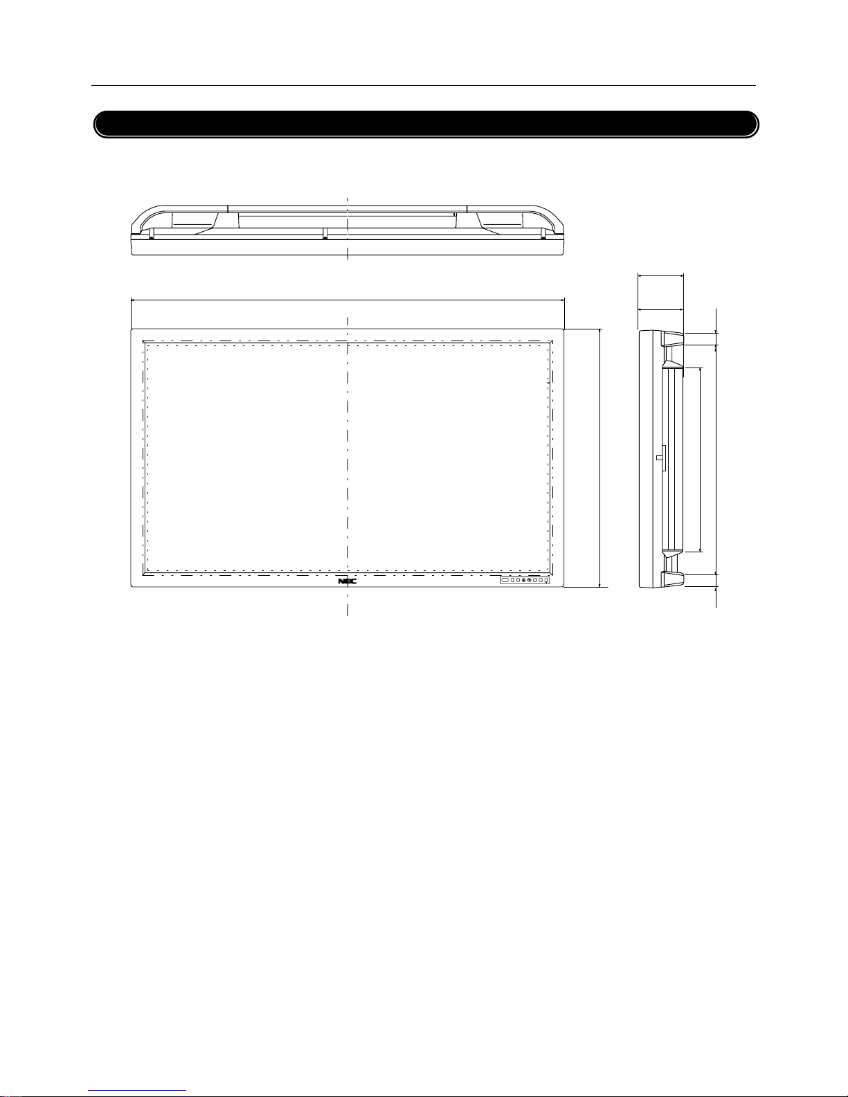
PLASMA MONITOR
† 69
Cabinet dimensions
Appendix
47.8''(1214)
28.6''(727)
20.8''(528)
1.4''(35.8)
1.4''(35.8)
25.06''(636.45)
5.1''
(129)
5.0''
(127)
PlasmaSync 50PD2 (Model PX-50VP2A)
Unit : inch (mm)
Page 71

NEC Technologies, Inc.
1250 N. Arlington Heights Road, Suite 500
Itasca, Illinois 60143-1248
Printed in Japan
7S800211
Page 72

User’s Manual
Bedienungshandbuch
Manuel de l'utilisateur
Page 73
E-2
†
PLASMA MONITOR
Important Information
Warnings and Safety Precaution
The NEC plasma monitor is designed and manufactured to provide long, trouble-free service. No maintenance other than cleaning is required. Use a soft dry cloth to clean the panel. Never use
solvents such as alcohol or thinner to clean the panel surface.
The plasma display panel consists of fine picture elements (cells).
Although NEC produces the plasma display panels with more than
99.99 percent active cells, there may be some cells that do not
produce light or remain lit.
For operating safety and to avoid damage to the unit, read carefully and observe the following instructions.
To avoid shock and fire hazards:
1. Provide adequate space for ventilation to avoid internal heat
build-up. Do not cover rear vents or install in a closed cabinet
or shelves.
The unit is equipped with cooling fans. If you install the unit in
an enclosure, be sure there is adequate space at the top of the
unit to allow hot air to rise and escape.
If the monitor becomes too hot, the overheat protector will be
activated and the monitor will be turned off. If this happens,
turn off the power to the monitor and unplug the power cord. If
the room where the monitor is installed is particularly hot, move
the monitor to a cooler location, and wait for the monitor to
cool for 60 minutes. If the problem persists, contact your NEC
dealer for service.
2. Do not use the power cord polarized plug with extension cords
or outlets unless the prongs can be completely inserted.
3. Do not expose unit to water or moisture.
4. Avoid damage to the power cord, and do not attempt to modify
the power cord.
5. Unplug unit during electrical storms or if unit will not be used
over a long period.
6. Do not open the cabinet which has potentially dangerous high
voltage components inside. If the unit is damaged in this way
the warranty will be void. Moreover, there is a serious risk of
electric shock.
7. Do not attempt to service or repair the unit. NEC is not liable
for any bodily harm or damage caused if unqualified persons
attempt service or open the back cover. Refer all service to
authorized NEC Service Centers.
RISK OF ELECTRIC SHOCK
DO NOT OPEN
CAUTION:
TO REDUCE THE RISK OF ELECTRIC SHOCK, DO
NOT REMOVE COVER. NO USER-SERVICEABLE
PARTS INSIDE. REFER SERVICING TO QUALIFIED SERVICE PERSONNEL.
This symbol warns the user that uninsulated voltage within the unit may have sufficient magnitude
to cause electric shock. Therefore, it is dangerous
to make any kind of contact with any part inside of
this unit.
This symbol alerts the user that important literature concerning the operation and maintenance
of this unit has been included. Therefore, it should
be read carefully in order to avoid any problems.
WARNING
TO PREVENT FIRE OR SHOCK HAZARDS, DO NOT EXPOSE THIS UNIT TO RAIN OR MOISTURE. ALSO DO NOT
USE THIS UNIT'S POLARIZED PLUG WITH AN EXTENSION
CORD RECEPTACLE OR OTHER OUTLETS, UNLESS THE
PRONGS CAN BE FULLY INSERTED. REFRAIN FROM
OPENING THE CABINET AS THERE ARE HIGH-VOLTAGE
COMPONENTS INSIDE. REFER SERVICING TO QUALIFIED SERVICE PERSONNEL.
WARNING
This is a Class A product. In a domestic environment this product
may cause radio interference in which case the user may be required to take adequate measures.
Precautions
Please read this manual carefully before using your NEC plasma
monitor and keep the manual handy for future reference.
CAUTION
Page 74
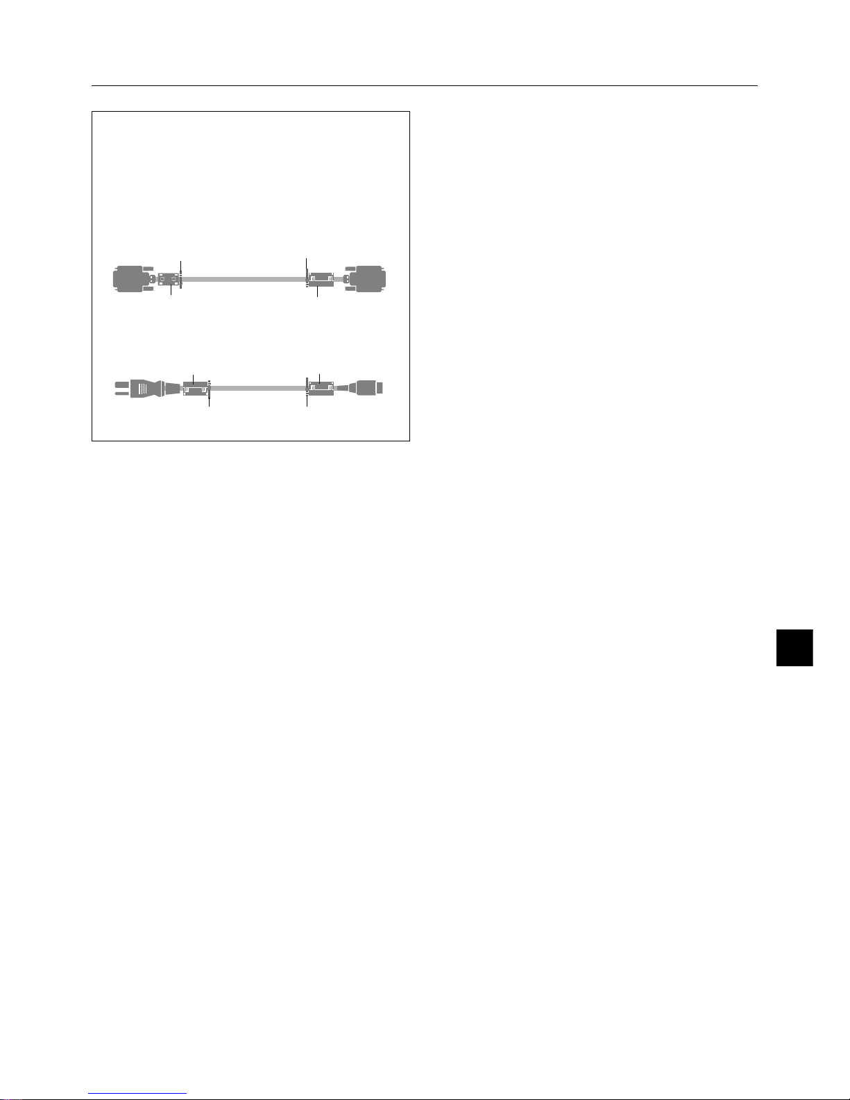
PLASMA MONITOR
† E-3
NOTE:
When you connect a computer to this monitor, attach the supplied ferrite cores. If you do not do this, this monitor will not
conform to mandatory FCC standards.
Attaching the ferrite cores.
Set the ferrite cores on both ends of the DVI cable (not supplied), and at both ends of the power cable (supplied).
Close the lid tightly until the clamps click.
Set side
(Plasma Monitor side)
DVI cable (not supplied)
core (small)
core (small)
Connector
Power cable (supplied)
core (large)
band
band
band
Recommendations to avoid or minimize phosphor
burn-in
Like all phosphor-based display devices and all other gas plasma
displays, Plasma monitors can be susceptible to phosphor burn
under certain circumstances. Certain operating conditions, such
as the continuous display of a static image over a prolonged period of time, can result in phosphor burn if proper precautions are
not taken. To protect your investment in this NEC plasma monitor, please adhere to the following guidelines and recommendations for minimizing the occurrence of image burn:
* Always enable and use your computer's screen saver function
during use with a computer input source.
* Display a moving image whenever possible.
* Always power down the monitor when you are finished using it.
NEC has built-in several operating modes in your PlasmaSync PD
Series monitor to help you reduce the likelihood of phosphor burn.
These are called the AccuShield Phosphor Protection System. If
the Plasmasync monitor is in long-term use or continuous operation, use the functions available in AccuShield to reduce the likelihood of perceptible phosphor burn or to diminish its perceptible
effects if it occurs. See pages E-34, 42 and 43 for instructions on
how to use the Orbiter, Low Brightness and Inverse RGB modes
of AccuShield.
* Lower the Brightness and Contrast levels as much as possible
without impairing image readability.
* Display an image with many colors and color gradations (ie.
photographic or photo-realistic images).
* Create image content with minimal contrast between light and
dark areas. For example white characters on black backgrounds.
Use complementary or pastel colors whenever possible.
* Avoid displaying images with few colors and distinct, sharply
defined borders between colors.
Contact NEC Technologies at 1-800-836-0655 for other recommended procedures that will best suit your particular application
needs.
To avoid damage and prolong operating life:
1. Use only with 120V 50/60Hz AC power supply. Continued operation at line voltages greater than 120 Volts AC will shorten
the life of the unit, and might even cause a fire hazard.
2. Handle the unit carefully when installing it and do not drop.
3. Set the unit away from heat, excessive dust, and direct sunlight.
4. Protect the inside of the unit from liquids and small metal objects. In case of accident, unplug the unit and have it serviced
by an authorized NEC Service Center.
5. Do not hit or scratch the panel surface as this causes flaws on
the surface of the screen.
6. For correct installation and mounting it is strongly recommended to use a trained, authorized NEC dealer.
7. As is the case with any phosphor-based display (like a CRT
monitor, for example) light output will gradually decrease over
the life of a Plasma Display Panel.
Important Information
core (large)
band
Page 75

E-4
†
PLASMA MONITOR
Contents
Important Information ................................................................................................................... E-2
Contents ........................................................................................................................................ E-4
How to Attach Options to the Plasma Monitor .............................................................................. E-5
Introduction ................................................................................................................................... E-6
Part Names and Functions ............................................................................................................ E-7
Control Panel ............................................................................................................................................... E-7
Terminal Panel .............................................................................................................................................. E-8
Remote Control ............................................................................................................................................ E-9
Operating Range for the Remote Control ..................................................................................................... E-9
Setup Procedure ........................................................................................................................................ E-10
Connections ................................................................................................................................ E-11
Wiring Diagram .......................................................................................................................................... E-11
Connecting Your PC or IBM compatible .................................................................................................... E-12
Connecting Your Macintosh Computer ...................................................................................................... E-13
Connections with Equipment that has a Digital Interface ........................................................................... E-14
Connecting Your VCR ................................................................................................................................ E-15
Connecting Your DVD Player...................................................................................................................... E-16
Connecting Your Stereo Amplifier .............................................................................................................. E-17
Basic Operation ........................................................................................................................... E-18
Turning on the Main Power and Return to Standby Mode ......................................................................... E-18
Turning On or Off the Power with the Remote Control ............................................................................... E-18
Power Management Function .................................................................................................................... E-19
Selecting a computer or video source........................................................................................................ E-19
Menu Operations (On-screen Menu)............................................................................................ E-20
Buttons Used in Menu Operations ............................................................................................................. E-22
Operation of the Menu Screen ................................................................................................................... E-22
Configuration Menu (CONFIG MENU) .......................................................................................... E-23
Audio Settings (SOUND) .............................................................................................................. E-24
Picture Adjustments (VISUAL CONTROL) .................................................................................... E-25
Auto Picture/Wide Screen Settings (AUTO PICTURE).................................................................. E-26
Clock Frequency/Clock Phase Adjustment, and RGB Mode Adjustment (AUTO PICTURE) ...................... E-26
Wide Screen Setting (WIDE MODE) ........................................................................................................... E-27
Horizontal/Vertical Position Adjustments (H-POSITION and V-POSITION) ................................... E-28
Direct Adjustment....................................................................................................................................... E-28
Menu Adjustments ..................................................................................................................................... E-29
Input Selection (INPUT SELECT) ................................................................................................. E-30
Standard Settings (NORMAL) ....................................................................................................... E-31
Information Screen (DISPLAY MODE) .......................................................................................... E-32
Timer Settings (PRESENT TIME) ................................................................................................. E-33
Time Settings ............................................................................................................................................. E-33
Timer Settings ............................................................................................................................................ E-33
4-Screen/9-Screen Multiple System Settings (VIDEO WALL MENU)............................................ E-35
Menu Display Position Adjustment (OSM LOCATION) .................................................................. E-36
Other Functions (OTHER SETTINGS) ........................................................................................... E-37
Color System Settings (COLOR SYSTEM) ................................................................................................. E-37
Power-On Mode Setting (P-ON MODE) ..................................................................................................... E-37
Power Management Settings (POWER MANAGER) ................................................................................... E-38
POWER/STANDBY Indicator ............................................................................................................... E-39
ID Number Setting (SET ID NO) ................................................................................................................. E-40
RGB 3 Adjustment (RGB 3 ADJUST) ......................................................................................................... E-40
Cinema Mode Setting (CINEMA MODE) ..................................................................................................... E-41
Long Life Settings (LONG LIFE MODE) ........................................................................................ E-42
Long Life Settings (LONG LIFE MODE) ...................................................................................................... E-42
Gray Level Settings (GRAY LEVEL) ............................................................................................................ E-43
Color Temperature Adjustment (COLOR TEMP) .......................................................................... E-44
Appendix ..................................................................................................................................... E-45
Opening the Terminal Cover ....................................................................................................................... E-45
Removing the Terminal Cover .................................................................................................................... E-45
Mounting of the Remote Control Holder .................................................................................................... E-45
Placing the Remote Control into the Remote Control Holder ..................................................................... E-46
Extending the Simple Feet ......................................................................................................................... E-46
Attaching the Ferrite Cores ........................................................................................................................ E-47
Pin Configuration and Signal Level of Mini D-Sub 15-Pin (Analog) Input Connector .................................. E-48
Pin Configuration and Functions of External Control Connector (Mini D-Sub 9 -Pin) ................................. E-48
Command Reference List .................................................................................................................... E-50
Pin Configuration and Signal of the RGB 3 IN Connector (DVI Connector) ................................................ E-61
Optional Accessories ................................................................................................................................. E-61
Signal Identification For Raster Preset........................................................................................................ E-62
Specifications ............................................................................................................................................. E-63
Troubleshooting .......................................................................................................................................... E-64
Cabinet dimensions ................................................................................................................................... E-66
Page 76
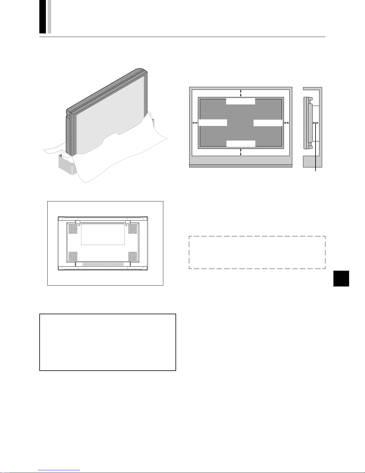
PLASMA MONITOR
† E-5
How to Attach Options to the Plasma Monitor
You can attach your optional mounts or stand to the plasma monitor in one of the following two ways:
In the upright position.
Lay the screen face down.
Lay the protective sheet, which was wrapped around the monitor
when it was packaged, beneath the screen surface so as not to
scratch the screen face.
This device cannot be used or installed without a separate
Tabletop Stand or other optional mounting accessory. For
proper installation it is strongly recommended to use a
trained, NEC authorized service person. Failure to follow
correct mounting procedures could result in damage to the
equipment or injury to the user or installer. Product warranty does not cover damage caused by improper installation. Failure to follow these recommendations could result in voiding your warranty.
Ventilation Requirements for enclosure
mounting
To allow heat to disperse, leave space between surrounding objects as shown in the diagram to the right.
50mm (1.97”)
50mm (1.97”)
31mm (1.22”)
31mm (1.22”)
45mm
(1.77”)
Pulling Out and Reinserting the Retractable Feet
Notice:
See "Extending the Simple Feet" on page E-46.
* Installation of only the main unit is not possible. Be sure to use
and install the main unit in conjunction with a stand or special
unit.
NOTE: RETRACTABLE FEET ARE FOR TEMPORARY USE ONLY AND ARE
NOT INTENDED FOR PERMANENT INSTALLATION.
MODEL # PX-42VPU1-ST STAND IS REQUIRED FOR PERMANENT TABLETOP INSTALLATION.
REPLACE THE FEET WHEN YOU MOVE THE MONITOR.
Page 77

E-6
†
PLASMA MONITOR
OSM and IPM are trademarks of NEC Technologies, Inc.
IBM PC/AT, PS/2, VGA, S-VGA, 8514/A and XGA are registered
trademarks of International Business Machines Corporation.
Apple and Macintosh are registered trademarks of Apple Computer, Inc.
Microsoft is a registered trademark of Microsoft Corporation. Windows is a trademark of Microsoft Corporation.
Introduction to the PlasmaSync 50PD2
This section introduces you to your new PlasmaSync 50PD2, provides a list of materials that comes with your monitor and describes
the features and controls.
The features you’ll enjoy include:
* This unit can be used with IBM PC/AT, Macintosh, and com-
patibles.
(For details, see “Signal Identification For Raster Preset” Pg.E-62)
* Easy-to-operate remote control and external control connector.
* Wired/Wireless Remote Control PX-RC2U (optional) can be used
as a wireless or as a wired remote control (with automatic switch-
ing by cable connection) and the remote THROUGH OUT con-
nector permits simultaneous operation of multiple monitors.
(A maximum of 3 units can be connected.)
The external control connector with a THROUGH OUT feature
permits various control functions to be made externally.
* ID No. settings can be made for up to 256 units.
* NTSC, PAL, SECAM, and M-NTSC composite video signals can
be accommodated
Video signals from video cameras, video decks, video disc play-
ers, and other video equipment adhering to NTSC as well as
PAL, SECAM, and M-NTSC (with a 4.43 MHz chroma signal)
standards can be selected on screen.
* Varied set of input/output connectors
• Video input/output: BNC video connector, S-video connector.
Each type is equipped with its own THROUGH OUT connector, single system.
• Analog RGB input: mini D-Sub 15-pin connector, BNC (G, B,
R, H/CS, V connectors). BNC is equipped with its own
THROUGH OUT connector, single system.
• DVD/HD input/output: BNC (Y, Cb/Pb, Cr/Pr connectors)
BNC is equipped with its own THROUGH OUT connector,
single system.
• Audio input signals: Stereo RCAx2
• Audio output signals: Stereo RCAx1
* Component video input terminal for DVD, 15.75 kHz (Y,Cb,Cr)
* You can select RGB source or Component source for the 5BNC
terminal (RGB2/DVD/HD). When selecting an RGB input, the
source is switched to the RGB input when selecting a compo-
nent input, the source is switched to the DVD/HD input.
* Can be used with Digital RGB input (DVI standard compliant)
* The signale plasma monitor provides four split screen feature.
* Can be used with multiple screens : 4-screen and 9-screen
VIDEO WALL (For 9-screen, an optional distribution amplifier is
needed for VIDEO WALL )
* Power management function
RGB3 input mode complies with DMPM (Digital Monitor Power
Management) of DVI.
A great reduction in power consumption when not being used is
achieved through the VESA-proposed DPMS system.
The unit can also be used with the Energy Star standard (in
which case power consumption will be 15 W or less when not
being used).
* The personal computer and the operating system that are to be
connected must be compatible with VESA DPMS.
Personal computers that are to be connected to the RGB3 input
must be compatible with DVI DMPM.
Introduction
* OSM (On Screen Manager) function
The OSM function displays a variety of screen adjustment and
correction menus on the screen to allow fine settings to be made.
* Plug and Play compatible
Plug and Play supports VESA DDC1 and DDC level B.
(VESA DDC1 and DDC2 level B)
The RGB3 input is compatible with DDC2 level B only.
* Can be used with RS-232C
* IBM PC/AT is a registered trademark of International Busi-
ness Machines Corporation.
* Macintosh is a registered trademark of Apple Computer, Inc.
* VESA is a trademark of Video Electronics Standard Associa-
tion.
* DVI is an abbreviation for Digital Visual Interface.
Contents of the Package
The following lists all of the items included in your plasma monitor
package. Please save the original box and packing materials for
future transportation or shipment of this monitor.
1. Plasma monitor1
2. Power cable1
3. Wireless remote control1
4. AA battery2
5. Remote control holder1
6. RGB signal cable
(mini D-sub 15-pin to mini D-sub 15-pin)1
7. Stopper2 *
8. Screw2 *
9. Ferrite core (large)2
10. Ferrite core (small)2
11. User's manual1
* These are fittings for fastening the unit to a wall to prevent tip-
ping due to external shock when using the stand (option).
Fasten the safety fittings to the holes in the back of the monitor
using the safety fitting mount screws.
Option
• Wired/ Wireless Remote Control
• Wall mount unit
• Ceiling mount unit
• Tilt mount unit
• Tabletop stand
• Others
Page 78
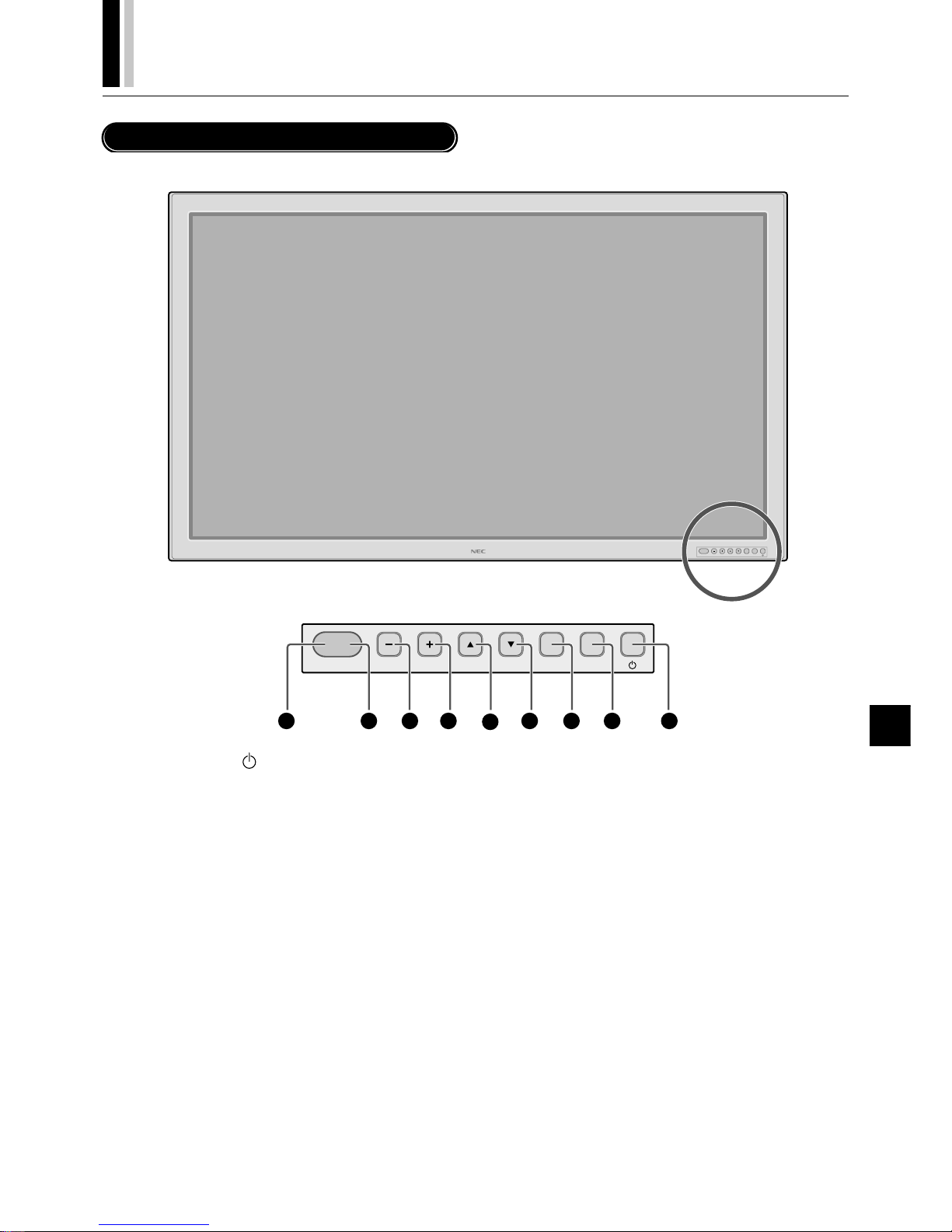
PLASMA MONITOR
† E-7
POWER/STANDBY
RGBVIDEO EXITDOWNUPPROCEED
1
Part Names and Functions
Control Panel
2
3
4
5
6
789
q POWER button ( )
Switches the main power on/off. See also page E-18.
w EXIT button
Exits the on-screen menu (OSM) mode. See also page E-22.
e PROCEED button
Sets the on-screen menu (OSM) mode and displays the onscreen menu. See also page E-22.
r DOWN (▼) button
Functions as the ▼ button in the on-screen menu (OSM) mode.
See also page E-22.
t UP (▲)button
Functions as the ▲ button in the on-screen menu (OSM) mode.
See also page E-22.
y RGB (+) button
Switches to the signal connected with the RGB input connector. (Toggle switches between [RGB1], [RGB2] / [DVD/HD], or
[RGB3].)
Functions as the (+) button in the on-screen menu (OSM) mode.
See also pages E-19 and 22.
u VIDEO (–) button
Switches to the signal connected with the VIDEO input con-
nector.
Functions as the (–) button in the on-screen menu (OSM) mode.
See also pages E-18 and 22.
i Remote control sensor
Receives the signal from the remote control (when using the
wireless remote control). See also page E-9.
o POWER/STANDBY
The lamp color indicates the mode of power on/standby or
power management. See also page E-18.
* When the "CONTROL LOCK" toggle switch on the monitor's
input panel is set to "ON", the buttons on the set's front bezel
control panel do not function.
Page 79
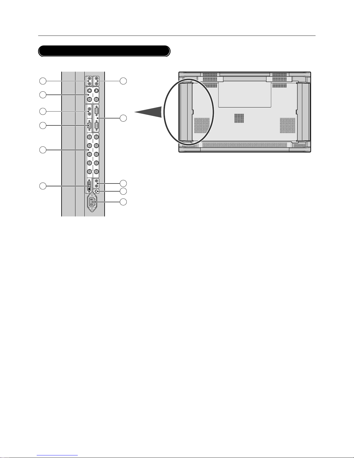
E-8
†
PLASMA MONITOR
Part Names and Functions
AUDIO
OUT
LR
AUDIO
IN 2
L
(
MONO
)
R
VIDEO
OUT
S-VIDEO VIDEO
AUDIO IN 1
EXTERNAL CONTROL
RGB 1
L
(
MONO
)
RIN
IN OUT
IN
OUT
IN
RGB 2
/
DVD
/
HD
G
/
Y B
/
C
B
/
P
B
H
/
CS VR
/
C
R
/
P
R
REMOTE
RGB 3
AC IN
IN OUT
C
/
L
IN
1
2
6
7
8
9
10
11
3
4
5
Terminal Panel
q AC IN connector
Connects with the supplied power cable.
w CONTROL LOCK
When "CONTROL LOCK" is set to "ON", the buttons on the
set's front bezel control panel do not function.
e REMOTE (Mini jack)
IN jack: When you use the remote control with a wire, attach it
here.
OUT jack: You can use this jack to output the remote control
signal from the REMOTE IN jack.
* This is used when operating multiple monitors (this plasma moni-
tor) with a single remote control.
r EXTERNAL CONTROL (mini D-Sub 9 pin)
IN connector: Use when operating the plasma monitor from
the optional equipment with EXTERNAL CONTROL.
OUT connector: You can use this connector to output the signal from the EXTERNAL CONTROL IN connector.
t AUDIO OUT
You can use this jack to output the audio signal from the AUDIO IN 1 or 2 jack.
y AUDIO IN 2
This is your audio input from your equipment such as a computer, VCR or DVD player.
u VIDEO
VIDEO IN connector (BNC): Here is where you connect a
composite video signal.
VIDEO OUT connector (BNC): You can use this connector to
output the composite video signal from the VIDEO IN connector.
S-VIDEO IN connector (DIN 4 pin): Here is where you con-
nect the S-video (Y/C separate signal).
* When connections are made to both the VIDEO connector and
the S-VIDEO connector, the signal of the S video connector
has priority.
S-VIDEO OUT connector (DIN 4 pin): You can use this con-
nector to output the S-video signal from the S-VIDEO IN con-
nector.
i AUDIO IN
This is your audio input from your equipment such as a com-
puter, VCR or DVD player.
o RGB 1 IN (mini D-Sub 15 pin)
Connect the analog RGB signal of a personal computer or other
RGB equipment.
!0 RGB 2/DVD/HD [G/Y, B/Cb/Pb, R/Cr/Pr, H/CS, V] (BNC)
IN connector: Connect the analog RGB signal or other RGB
equipment.
The H/V composite signal is connected to the H/CS connec-
tor. Also this connects with your equipment such as a DVD
player and HDTV laser disk player. A Sync-on-Green signal
can be connected to the G/Y connector.
OUT connector: You can use this connector to output the sig-
nal from the RGB 2/DVD/HD IN connector.
!1 RGB 3 IN (DVI-I 29 pin)
Connects a digital RGB signal of a personal computer with a
digital RGB output.
* This connector does not support analog input.
Page 80
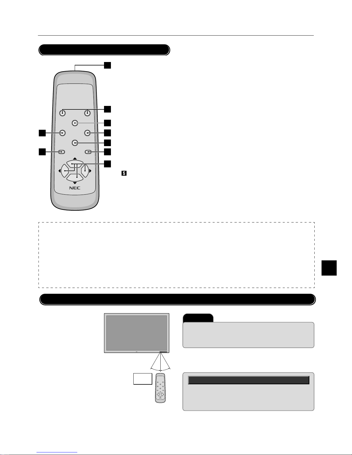
PLASMA MONITOR
† E-9
Part Names and Functions
POWER OFF
RGB 1
POWER ON
RGB 3
RGB 2/DVD/HD
VI DEO
EXI T
PROCEED
POSITION/CONTROL
RP-102
9
2
8
4
3
5
1
7
6
NOTE:
* The wired/wireless remote control PX-RC2U is available as an option.
* In addition to the features on the supplied remote control, the optional remote control has the following functions:
• Direct remote button operation for picture adjustments such as contrast and brightness.
• Direct remote button operation for picture and alignment adjustments such as horizontal and vertical position.
• When the remote control is connected to the REMOTE IN jack with the remote cable, the optional remote control can be used as the wired remote control.
The REMOTE OUT connector is used to connect multiple plasma monitors together and allows all of the plasma monitors to be controlled by one remote
control.
• When you control multiple plasma monitors by the single remote control, you can assign an ID number to each plasma monitor so that all of the plasma
monitors are not be affected at the same time.
POWER OFF
RGB 1
POWER ON
RGB 3
RGB 2/DVD/HD
VIDEO
EXIT
PROCEED
POSITION/CONTROL
RP-102
Important
The remote control system may not function when direct sunlight or strong
illumination strikes the remote control sensor of the plasma monitor, or
when there is an obstacle in the path. Should this happen, use the remote
control in the wired operation.
Handling the remote control
Remote Control
¡ POWER ON/OFF button
Switches the power on/off. See also
page E-18.
* If the POWER/STANDBY lamp is not
glowing, then these controls will not
work.
™ RGB 1 button
Select the RGB1 input. See also page
E-19.
£ RGB 2 button
Select the RGB 2/DVD/HD input. See
also page E-19.
¢ RGB 3 button
Select the RGB 3 input. See also page
E-19.
VIDEO button
Select the VIDEO input. See also page
E-19.
§ POSITION/CONTROL buttons
Adjust the image location horizontally and vertically. See also pages E-22 and 28.
These buttons executes the menu selection and
confirms adjustments/setting in the menu mode.
¶ PROCEED button
Displays the on-screen menu (Menu mode).
See also page E-22.
• EXIT button
Exits the on-screen menu or Menu mode. See
also page E-22.
ª Infrared transmitter
Direct the remote control toward the remote
sensor on the plasma monitor. See also page
E-9.
Operating Range for the Remote Control
Point the top of the remote
control toward the plasma
monitor's remote sensor
during button operation.
Use the remote control
within a distance of about 7
m/23 ft. from the front of the
plasma monitor's remote
control sensor and at a horizontal and vertical angle of
within 30˚.
Approx.
7m/23ft
30˚ 30˚
* Do not subject to strong shock.
*
Do not allow water or other liquid to splash the remote control.
If the remote control gets wet, wipe it dry immediately.
* Avoid exposure to heat and steam.
Page 81
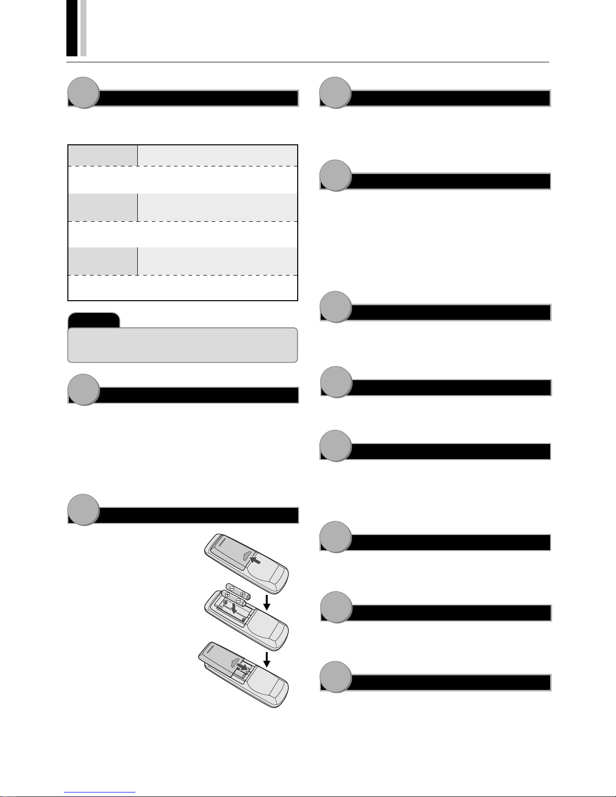
E-10
†
PLASMA MONITOR
11
10
9
8
7
6
5
4
3
2
1
Setup Procedure
Determine the installation location
Installation of only the plasma monitor is not possible. Be sure to
use and install the plasma monitor in conjunction with a stand or
special unit.
CAUTION
DO NOT ATTEMPT TO INSTALL THE
PLASMA MONITOR.
Installing your plasma display must be done by a qualified technician. Contact your dealer for more information.
CAUTION
DO NOT USE THE RETRACTABLE FEET
FOR PURPOSE OF PERMANENT INSTALLATION.
The retractable feet are for temporary use only and are not intended for permanent installation.
CAUTION
MOVING OR INSTALLING THE PLASMA
MONITOR MUST BE DONE BY TWO OR
MORE PEOPLE.
Failure to follow this caution may result in injury if the plasma
monitor falls.
Important
Lay the protective sheet, which was wrapped around the plasma monitor
when it was packaged, beneath the plasma monitor so as not to scratch the
panel.
Install the plasma monitor
The connections of two or more plasma monitors may degrade
image quality on the remaining connected units connected to the
loop out. Consider the cable length or cable type to be used.
Note that only one plasma monitor connection is possible for loopout.
Install the remote control batteries
The remote control is powered by 1.5
V AA magnesium batteries.
To install or replace batteries:
¡ Press and slide to open the cover.
™ Align the batteries according to
the (+) and (–) indications inside
the case.
£ Replace the cover.
Connect external equipment (See page E-11)
• To protect the connected equipment, turn off the main power
before making connections.
• Refer to your equipment user manual.
Connect the supplied power cable
• The power outlet socket should be installed as near to the equipment as possible, and should be easily accessible.
• Attach the supplied ferrite cores to the power cable. See page
E-
47.
• Fully insert the prongs into the power outlet socket. Loose connection may cause noise.
• The maximum power consumption 570 W (the maximum current rating 6.0 A)
Switch on the power of all the attached external equipment
When connected with a computer, switch on the power of the computer first.
Operate the attached external equipment.
Display the signal on the external equipment you wish.
Select the input mode
(See pages E-19 and 24)
Select the appropriate input.
When the equipment is connected to the RGB 2/DVD/HD, make
the setting for the RGB 2 input. When an audio signal is connected,
make the setting for sound.
Adjust the sound (See page
E-
24)
Make adjustments when adjustment of the volume or balance is
required.
Adjust the screen (See pages
E-
28 and 29)
Make adjustments when adjustment of the screen display position
or distortion is required.
Adjust the image (See page
E-
25)
Make adjustments when picture adjustment such as the brightness or contrast is required.
Page 82
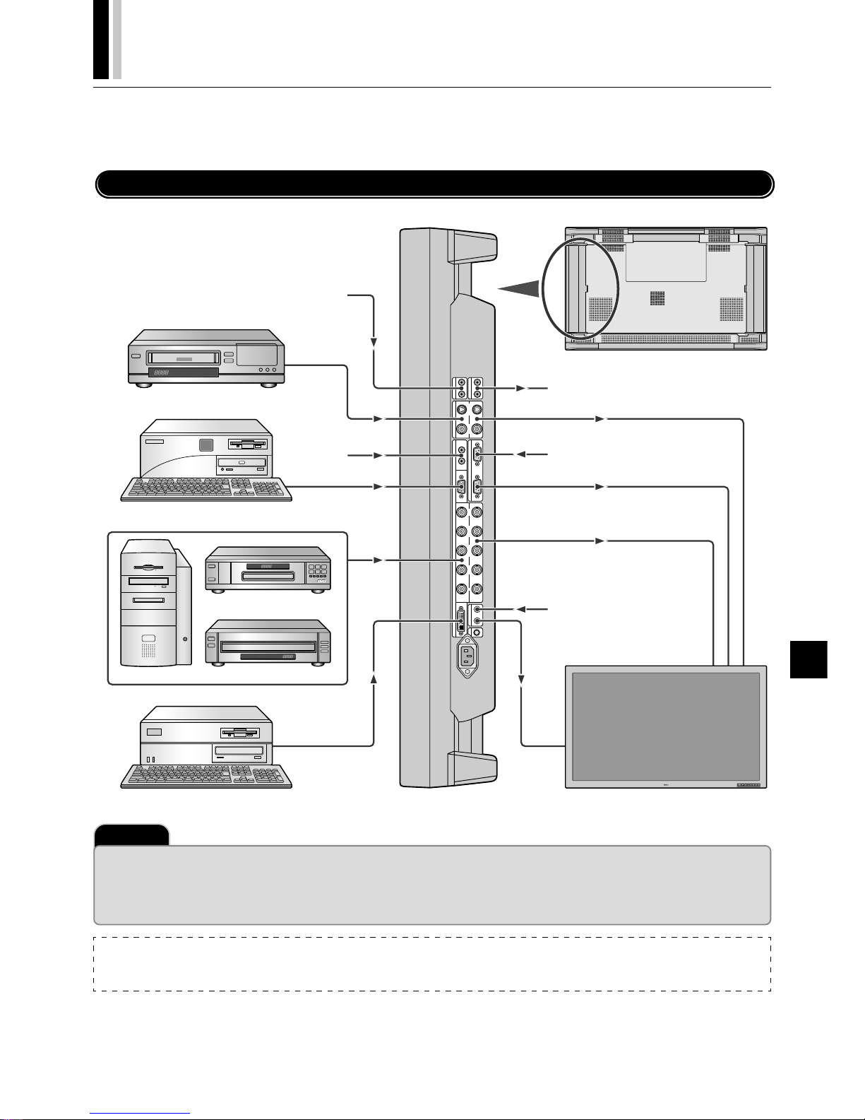
PLASMA MONITOR
† E-11
Connections
Before making connections:
* First turn off the power of all the attached equipment and make connections.
* Refer to the user manual included with each equipment.
Wiring Diagram
AUDIO
OUT
LR
AUDIO
IN 2
L
(
MONO
)
R
VIDEO
OUT
S-VIDEO VIDEO
AUDIO IN 1
EXTERNAL CONTROL
RGB 1
L
(
MONO
)
RIN
IN OUT
IN
OUT
IN
RGB 2
/
DVD
/
HD
G
/
Y B
/
C
B
/
P
B
H
/
CS VR
/
C
R
/
P
R
REMOTE
RGB 3
AC IN
IN OUT
C
/
L
IN
Equipment with digital interface
Plasma monitor
Amplifier
External control equipment
Wired remote control (optional)
Plasma monitor (second monitor)
Audio signal of input device
VCR
Audio signal of
input device
Personal computer
DVD player
Personal computer
HD laser disk player
NOTE:
VIDEO connector
S-VIDEO IN connector will take preference over VIDEO IN connector when a component is connected to each connector.
Important
Four / Nine Multiple Screens System (VIDEO WALL MENU)
* Multiple System requires the optional Multiple Unit. Contact your dealer for more information.
* Use an optionally available BNC-typed signal cable that is within 1 to 2 m (3.3 to 6.6 feet) when one plasma monitor is connected to another one with the plasma
monitor 's OUT and IN connectors.
If image is degraded, use an optionally available distribution instead of using the OUT connector on the plasma monitor.
Page 83
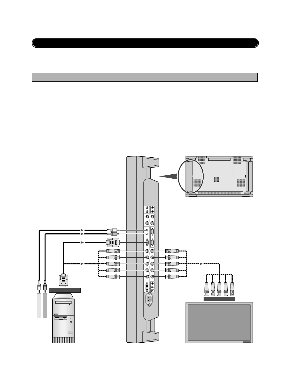
E-12
†
PLASMA MONITOR
Connecting Your PC or IBM compatible
Connecting your PC to your Plasma monitor will enable you to display your computer's screen image.
Some video cards may not display an image correctly.
If you wish to input wide signals, make the “RGB MODE” and “INPUT MODE” settings.
(See "Signal Identification For Raster Preset" on page E-62.)
Connect the Plasma Monitor to Your PC or IBM Compatible
• To connect the RGB 1 IN connector (mini D-sub 15 pin) on the plasma monitor, use the supplied RGB signal cable (mini D-sub 15 pin to
mini D-sub 15 pin).
• To connect the RGB 2/DVD/HD IN connector (BNC) on the plasma monitor, use the optional signal cable (mini D-sub 15 pin to BNC x 5).
Select [RGB] for RGB 2 from the INPUT SELECT menu.
When connecting one or more Plasma monitors, use the RGB 2/DVD/HD OUT connector (BNC).
• The AUDIO IN 1 and 2 can be both used for audio input. For connection, select [INPUT 1] or [INPUT 2] from the SOUND menu.
Connections
AUDIO
OUT
LR
AUDIO
IN 2
L
(
MONO
)
R
VIDEO
OUT
S-VIDEO VIDEO
AUDIO IN 1
EXTERNAL CONTROL
RGB 1
L
(
MONO
)
RIN
IN OUT
IN
OUT
IN
RGB 2
/
DVD
/
HD
G
/
Y B
/
C
B
/
P
B
H
/
CS VR
/
C
R
/
P
R
REMOTE
RGB 3
AC IN
IN OUT
C
/
L
IN
Plasma monitor
Plasma monitor (second monitor)
To audio right output
To RGB 2/DVD/HD IN
BNC x 5
BNC x 5
RCA
Mini D-sub 15 pin
BNC x 5
Mini D-sub 15 pin
To analog RGB output
PC or IBM compatible
To audio left output
Page 84
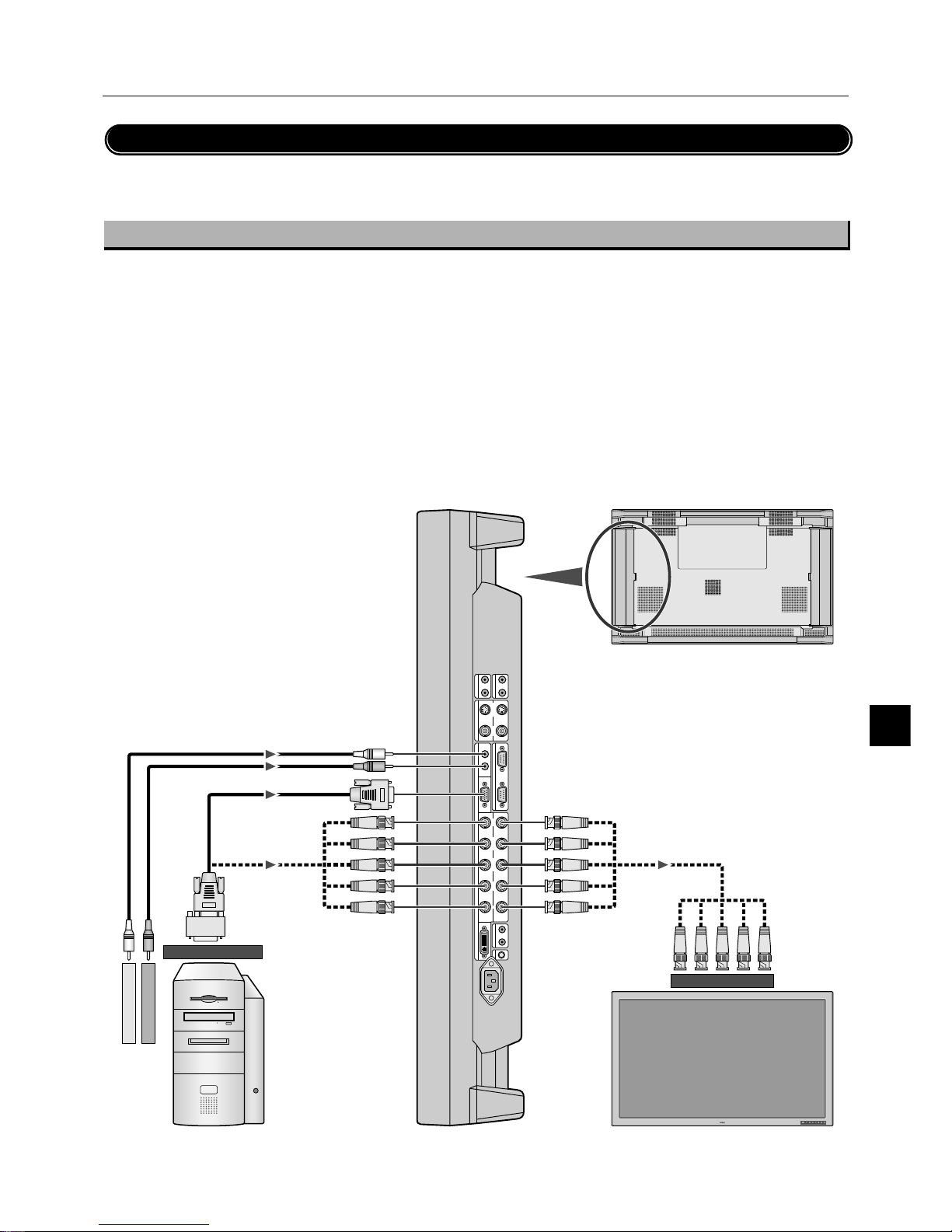
PLASMA MONITOR
† E-13
Connecting Your Macintosh Computer
Connecting your Macintosh computer to your Plasma monitor will enable you to display your
computer's screen image. Some video cards or drivers may not display images correctly. (See also "Signal Identification For Raster
Preset" on page E-62.)
Connect the Plasma Monitor to Your Macintosh
• To connect the RGB 1 IN connector (mini D-sub 15 pin) on the plasma monitor, use the supplied RGB signal cable (mini D-sub 15 pin to
mini D-sub 15 pin).
For older Macintosh, use a pin adapter for Macintosh (available separately) to connect to your Macintosh's video port.
The resolution modes that you can select are:
• 13" fixed mode • 16" fixed mode • 19" fixed mode
• To connect the RGB 2/DVD/HD IN connector (BNC) on the plasma monitor, use the signal cable available separately (mini D-sub 15 pin
to BNC x 5).
Select [RGB] for [RGB 2] from the INPUT SELECT menu.
When connecting one or more Plasma monitors, use the RGB 2/DVD/HD OUT connector (BNC).
• If you use with a Macintosh PowerBook, set "Mirroring" to Off.
Refer to your Macintosh's owner's manual for more information about your computer's video output requirements and any special
identification or configuring your monitor's image and monitor may require.
• The AUDIO IN 1 and 2 (both RCA) can be both used for audio input. For connection, select [INPUT 1] or [INPUT 2] from the SOUND
menu.
AUDIO
OUT
LR
AUDIO
IN 2
L
(
MONO
)
R
VIDEO
OUT
S-VIDEO VIDEO
AUDIO IN 1
EXTERNAL CONTROL
RGB 1
L
(
MONO
)
RIN
IN OUT
IN
OUT
IN
RGB 2
/
DVD
/
HD
G
/
Y B
/
C
B
/
P
B
H
/
CS VR
/
C
R
/
P
R
REMOTE
RGB 3
AC IN
IN OUT
C
/
L
IN
Plasma monitor
Plasma monitor (second monitor)
To audio right output
To RGB 2/DVD/HD IN
BNC x 5
BNC x 5
RCA
Mini D-sub 15 pin
BNC x 5
Mini D-sub 15 pin
To video output port
Macintosh
To audio left output
Connections
Pin adapter for
Macintosh
Page 85
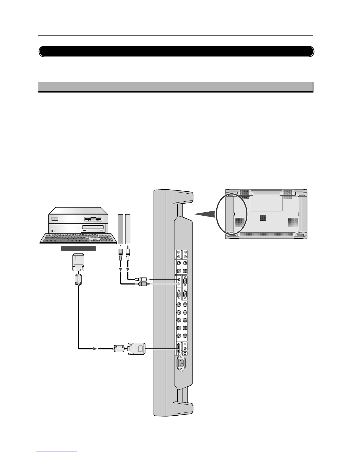
E-14
†
PLASMA MONITOR
Connections
Connections with Equipment that has a Digital Interface
Connections can be made with equipment that is equipped with a digital interface compliant with the DVI (Digital Visual Interface) standard.
If you wish to input wide signals, make the “RGB MODE” and “INPUT MODE” settings.
(See "Signal Identification For Raster Preset" on page E-62.)
Connect the Plasma Monitor to a Computer with a Digital Output
• To connect the RGB 3 IN connector on the plasma monitor, use a DVI 29-pin signal cable (available separately).
• The RGB 3 IN connector also accepts a DVI 25-pin (digital only) cable.
• Input TMDS signals conforming to DVI standards.
• To maintain display quality, use a cable with a quality prescribed by DVI standards that is within 5 meters (6.6 feet) in length.
• Attach the supplied small ferrite cores to the DVI signal cable. See page E-47 for attaching the ferrite cores.
• The AUDIO IN 1 and 2 (both RCA) can be both used for audio input. For connection, select [INPUT 1] or [INPUT 2] from the SOUND
menu.
AUDIO
OUT
LR
AUDIO
IN 2
L
(
MONO
)
R
VIDEO
OUT
S-VIDEO VIDEO
AUDIO IN 1
EXTERNAL CONTROL
RGB 1
L
(
MONO
)
RIN
IN OUT
IN
OUT
IN
RGB 2
/
DVD
/
HD
G
/
Y B
/
C
B
/
P
B
H
/
CS VR
/
C
R
/
P
R
REMOTE
RGB 3
AC IN
IN OUT
C
/
L
IN
To audio right output
To audio left output
Plasma monitor
RCA
RCA
DVI connector
Ferrite core
Ferrite core
DVI connector
To digital RGB output
Equipment with a digital interface such as a
personal computer with RGB output (TMDS)
Page 86
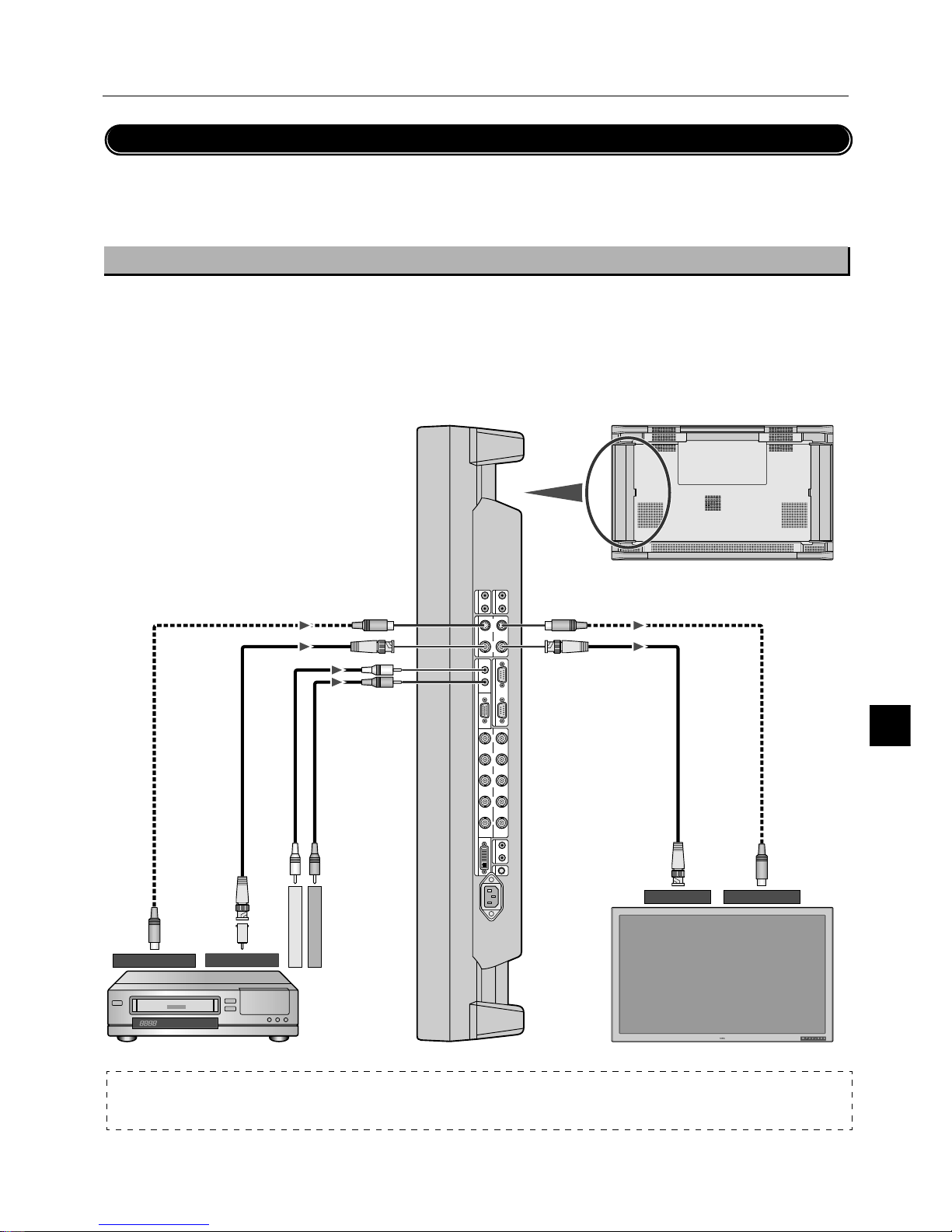
PLASMA MONITOR
† E-15
AUDIO
OUT
LR
AUDIO
IN 2
L
(
MONO
)
R
VIDEO
OUT
S-VIDEO VIDEO
AUDIO IN 1
EXTERNAL CONTROL
RGB 1
L
(
MONO
)
RIN
IN OUT
IN
OUT
IN
RGB 2
/
DVD
/
HD
G
/
Y B
/
C
B
/
P
B
H
/
CS VR
/
C
R
/
P
R
REMOTE
RGB 3
AC IN
IN OUT
C
/
L
IN
Connections
Connecting Your VCR
Connecting your VCR or laser disc player to your Plasma monitor will enable you to display your VCR' s or laser disc player' s video.
Refer to your VCR or laser disc player owner's manual for more information.
Connect the Plasma Monitor to a VCR or Laser Disc Player
• To connect the VIDEO IN connector (BNC) on the plasma monitor, use a separately available BNC connector cable. You will need a
separately available BNC-to-RCA adapter to connect a VCR or laser disc player with an RCA pin jack to the BNC connector cable.
• When connecting one or more Plasma monitors, use the VIDEO OUT connectors (BNC).
• The AUDIO IN 1 and 2 (both RCA) can be both used for audio input. For connection, select [INPUT 1] or [INPUT 2] from the SOUND
menu.
To audio right output
To audio left output
Plasma monitor
RCA
Plasma monitor (second monitor)
DIN 4 pin
BNC
BNC
DIN 4 pin
To VIDEO IN To S-VIDEO IN
BNC
DIN 4 pin
BNC
DIN 4
pin
To VIDEO OUT
To S-VIDEO OUT
BNC-to-RCA
adapter
VCR or Laser disc player
NOTE:
VIDEO connector
S-VIDEO IN will take precedence over VIDEO IN when a component is connected to each connector.
Page 87
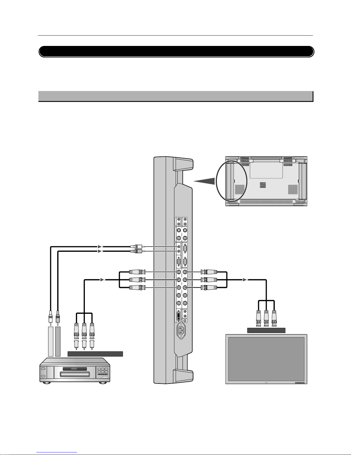
E-16
†
PLASMA MONITOR
Connections
Connecting Your DVD Player
Connecting your DVD player to your Plasma monitor will enable you to display your DVD' s video.
Refer to your DVD player owner's manual for more information.
* When a video filmed in frames per second (progressive) is played back, the plasma monitor takes the second and third frames, and
converts them into a progressive signal with 60 frames per second. Note that only NTSC and 480i at 60 Hz is available.
Connect the Plasma Monitor to a DVD Player
• To connect the RGB 2/DVD/HD IN connector (BNC) on the plasma monitor, use a separately available BNC connector cable. You will
need a separately available BNC-to-RCA adapter to connect a DVD player with an RCA pin jack to the BNC connector cable.
Some DVD players may have different connectors such as Y,Cb/Pb, and Cr/Pr.
Select [DVD/HD] for RGB 2 from the INPUT SELECT menu.
When connecting one or more Plasma monitors, use the RGB 2/DVD/HD OUT connectors (BNC).
• The AUDIO IN 1 and 2 (both RCA) can be both used for audio input. For connection, select [INPUT 1] or [INPUT 2] from the SOUND
menu.
AUDIO
OUT
LR
AUDIO
IN 2
L
(
MONO
)
R
VIDEO
OUT
S-VIDEO VIDEO
AUDIO IN 1
EXTERNAL CONTROL
RGB 1
L
(
MONO
)
RIN
IN OUT
IN
OUT
IN
RGB 2
/
DVD
/
HD
G
/
Y B
/
C
B
/
P
B
H
/
CS VR
/
C
R
/
P
R
REMOTE
RGB 3
AC IN
IN OUT
C
/
L
IN
Plasma monitor
Plasma monitor (second monitor)
BNC X3
BNC X3
BNC X3
RCA
BNC X3
BNC-to-RCA adapter
To audio right output
To audio left output
To DVD Component video output
To RGB 2/DVD/HD IN
DVD player
Page 88
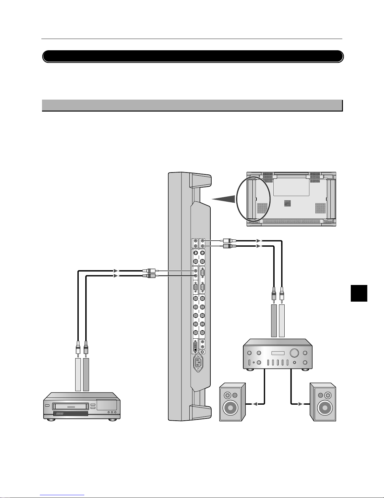
PLASMA MONITOR
† E-17
AUDIO
OUT
LR
AUDIO
IN 2
L
(
MONO
)
R
VIDEO
OUT
S-VIDEO VIDEO
AUDIO IN 1
EXTERNAL CONTROL
RGB 1
L
(
MONO
)
RIN
IN OUT
IN
OUT
IN
RGB 2
/
DVD
/
HD
G
/
Y B
/
C
B
/
P
B
H
/
CS VR
/
C
R
/
P
R
REMOTE
RGB 3
AC IN
IN OUT
C
/
L
IN
Connections
Connecting Your Stereo Amplifier
You can connect your stereo amplifier to your Plasma monitor. Refer to your amplifier owner's manual for more information.
Connect the Plasma Monitor to a Stereo Amplifier
• Turn on the plasma monitor and the amplifier only after all hookups have been made.
• Use an RCA cable to connect the AUDIO OUT connector (RCA) on the plasma monitor and the audio input on the amplifier.
• Do not reverse the audio left and right jacks.
• The AUDIO IN 1 and 2 (both RCA) can be both used for audio input. For connection, select [INPUT 1] or [INPUT 2] from the SOUND
menu.
• The AUDIO OUT jack outputs sound for the currently selected video.
To audio right input
To audio left input
Plasma monitor
RCA
Amplifier
VCR or Laser disc player
To audio right output
To audio left output
RCA
RCA
RCA
External speaker
External speaker
Page 89
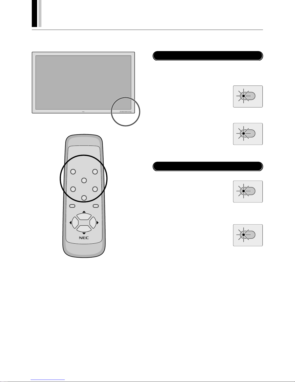
E-18
†
PLASMA MONITOR
Basic Operation
Before operating the remote control, be sure to turn on the main power to the plasma monitor.
EXITPROCEEDDOWNUPRGBVIDEO
POWER/STANDBY
POWER OFF
RGB 1
POWER ON
RGB 3
RGB 2/DVD/HD
VI DEO
EXI T
PROCEED
POSITION/CONTROL
RP-102
Turning on the Main Power and Return to Standby Mode
The plasma monitor enters the standby mode and the POWER/
STANDBY lamp is lit in orange when the power cable is plugged
into the wall outlet.
POWER/STANDBY
To turn the main power:
Press the POWER button on the front
panel of the plasma monitor
The main power will be turned on.
The POWER/STANDBY lamp is lit in green.
To turn off the power
(standby mode):
Press the POWER button again
The plasma monitor is in standby mode.
The POWER/STANDBY lamp is lit in orange.
POWER/STANDBY
Turning On or Off the Power with the Remote Control
POWER/STANDBY
To turn on the plasma monitor:
Make sure that the POWER/STANDBY
lamp is lit in orange (standby).
Press the POWER ON button on the remote control.
The plasma monitor is turned on.
The POWER/STANDBY lamp is lit in green.
To turn off the plasma monitor:
Press the POWER OFF button on the
remote control.
The plasma monitor enters the standby
mode.
The POWER/STANDBY lamp is lit in orange.
POWER/STANDBY
* The standby mode used here is the condition that exists when
the power management is on. This is not the standby mode set
by the remote control's powering-off.
Page 90
PLASMA MONITOR
† E-19
Basic Operation
To view a video source:
Press the VIDEO button.
Displays the image from the equipment connected to the VIDEO
IN connector.
• See page
E-
15 for connection.
To view the image from a computer,
DVD player or HD laser disc player:
Select [RGB] or [DVD/HD] for RGB 2 from the INPUT SELECT
menu.
Press the source button (RGB 1, RGB 2/DVD/HD, or RGB 3)
Displays the image from the computer, DVD player or HD laser
disc player connected to the selected RGB input connector.
• You can select the source also by using the RGB button on the
front panel.
To do this, each press of the RGB button selects [RGB 1] →
[RGB 2] or [DVD/HD] → [RGB 3] in sequence.
• See page
E-
11 for connection.
NOTE:
* The default input is the last input used, but the plasma monitor can be
configured to display either the last input used or a preset input whenever it is used turned on. (See "Power-On Mode Setting" on page E-37.)
* During RGB3 mode the power management function is available in Off-
state only. (This is Active-off Power state in DMPM of DVI standard.)
An image will be displayed in 4 seconds after TMDS signal is returned.
Important
Notes on the POWER/STANDBY lamp on the plasma monitor
* The POWER/STANDBY lamp 's flashing in alternately green and orange,
or flashing in green only indicates that the plasma monitor detects an
error. Should this happen, power off the plasma monitor immediately
and contact your dealer:
Selecting a computer or video source
POWER/STANDBY Lamp Status
Normal
Error
Main Power ON
Timer enabled
Power OFF with remote control
Main Power Standby
Abnormal heat warning
Panel damaged
Green
Orange flashing
Orange
Orange
Green flashing
Green and/or Orange flashing
Status POWER/STANDBY lamp
When Using Power Management Function
NOTE: In some cases the fan may stop running. This is not a malfunction.
This plasma monitor follows the VESA approved DPMS Power
Management function.
The power management function is an energy saving function that
automatically reduces the power consumption of the display when
the keyboard or the mouse has not been used for a fixed period.
The status of power management can be checked by POWER/
STANDBY lamp display.
See page E-39.
Page 91
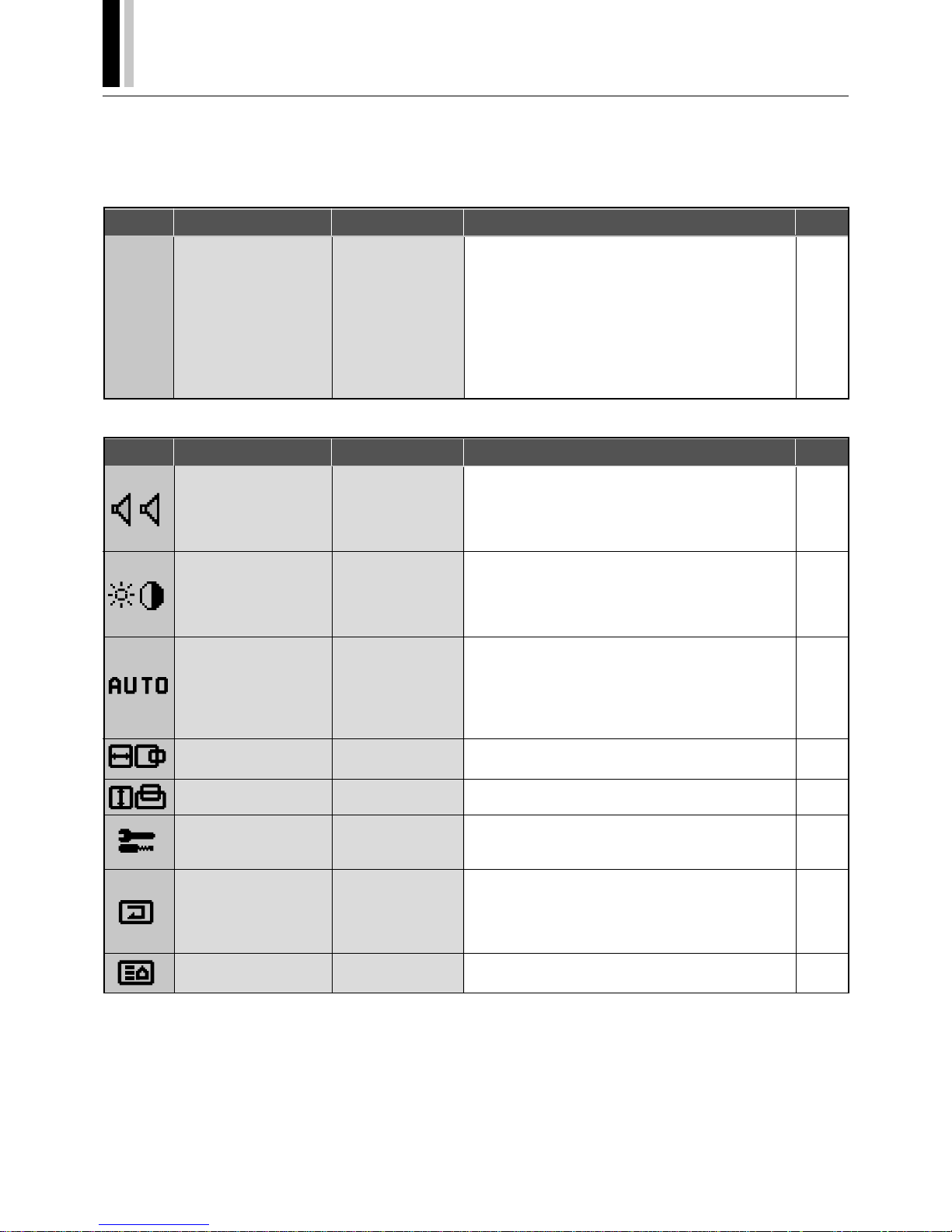
E-20
†
PLASMA MONITOR
Icon Configuration menu
Sub menu
Adjustment settings
Page
(None)
Sets whether or not the main menu is displayed.
Sets whether or not the second screen of the main menu
is displayed.
Sets whether or not wireless transmission of the remote
control is enabled.
Sets the sync signals that will be automatically selected.
Sets the brightness of the screen when there are multiple
screens.
Returns all adjustments and settings of CONFIG MENU to
the factory default values.
CONFIG MENU
(Configuration menu)
To display this menu, press
and hold the ▲ button and the
PROCEED button at the
same time for 3 seconds or
longer on the remote control
or the main unit.
OSD DISPLAY
OSD MODE
WIRELESS REMOTE
CONTROL
SYNC MODE
PLE LINK
ALL RESET
E-23
E-23
E-23
E-23
E-23
E-23
Menu Operations (On-screen Menu)
Use of the on-screen menu (OSM) function allows the setting of a variety of detailed adjustments. The adjustment settings are retained
even when the power is switched off.
The on-screen menu (OSM) function displays a menu on the screen from which the adjustments are made.
List of Setting Details
Icon Main menu
Sub menu
Adjustment settings
Page
SOUND
(Audio settings)
VOLUME
BALANCE
MUTE
INPUT1
INPUT2
Volume adjustment
Left-right balance adjustment
Mute setting
Sets audio input to AUDIO IN 1
Sets audio input to AUDIO IN 2
E-24
E-24
E-24
E-24
E-24
VISUAL CONTROL
(Picture adjustments)
BRIGHTNESS
CONTRAST
SHARPNESS
COLOR
TINT
Screen brightness adjustment
Image contrast adjustment
Image sharpness adjustment
Adjustment of color saturation
Tint adjustment
E-25
E-25
E-25
E-25
E-25
AUTO PICTURE
(Auto picture/Wide screen
settings)
AUTO PICTURE
INPUT MODE
RGB MODE
WIDE MODE
Automatic adjustment of clock frequency/clock phase
This is set when switching of input signal discrimination is
required.
Sets the mode (moving picture/still picture mode) to suit
the input signal.
WIDE MODE setting
E-26
E-26
E-26
E-27
H-POSITION
(Horizontal position adjustment)
H-POSITION
H-WIDTH
Horizontal position adjustment of the screen
Screen width adjustment
E-29
E-29
V-POSITION
(Vertical position adjustment)
V-POSITION
V-HEIGHT
Vertical position adjustment of the screen
Screen height adjustment
E-29
E-29
INPUT SELECT
(Input selection)
RGB2
SCART
RGB signal or DVD/HD signal setting
Sets whether or not the SCART jack is connected.
(not used in the United States.)
E-30
E-30
NORMAL
(Standard settings)
ALL RASTER NORMAL
ALL VISUAL NORMAL
ALL NORMAL
Returns the horizontal/vertical position and other adjustments of the screen to the default settings.
Returns the audio settings, picture, and color temperature
adjustments to the default settings.
Returns all adjustments and setting to default values.
E-31
E-31
E-31
(To Page 2)
Setting [OSD MODE] to [PRO] on the configuration menu
displays the second page of the main menu.
Main Menu Page 1 Items
Page 92
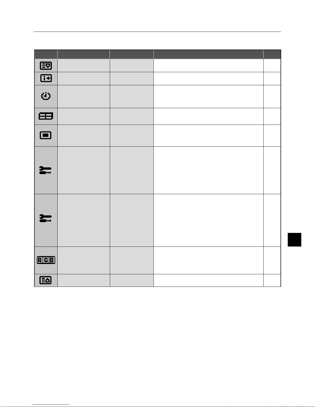
PLASMA MONITOR
† E-21
Icon Main menu
Sub menu
Adjustment settings
Page
(To Page 1)
Setting [OSD MODE] to [PRO] on the configuration menu
displays the first page of the main menu.
DISPLAY MODE
(Information screen)
SOURCE INFO. Allows verification of the currently input signal (data). E-32
PRESENT TIME
(Timer setting)
DATE
TIME
TIMER
Sets the date.
Sets the time.
Sets the "On/Off" time for switching the power and sets the
input mode.
E-33
E-33
E-33
VIDEO WALL MENU
(4-Screen/ 9-Screen Multiple System Settings)
SCREEN DIVIDER
POSITION
DISP MODE
Sets the number of screens to be used to 1, 4, or 9 screens.
Sets the screen position.
Sets the display mode.
E-35
E-35
E-35
OSM LOCATION
(Menu display position
adjustments)
OSM H-POS
OSM V-POS
OSM ANGLE
OSM DISPLAY TIME
Menu display horizontal position adjustment
Menu display vertical position adjustment
Sets the menu display as a horizontal or vertical screen.
Sets the menu display time.
E-36
E-36
E-36
E-36
COLOR SYSTEM
P-ON MODE
POWER MANAGER
SET ID NO
RGB3 ADJUST
CINEMA MODE
ALL RESET
OTHER SETTING
(Other settings)
Sets the color system (to AUTO, 3.58 NTSC, PAL, SECAM,
or 4.43 NTSC).
Sets the input mode that will be in effect when power is
switched on.
Sets the power management function.
Sets ID numbers for up to 256 units.
Set when the RGB 3 image is not stable.
Sets the cinema mode.
Returns the settings of all other functions to the default values.
E-37
E-37
E-38
E-40
E-40
E-41
E-40
LUM LIMIT
ORBITTING
INV/WT
PROG. ORBIT
GRAY LEVEL
ALL RESET
LONG LIFE MODE
(Long Life settings)
Limits screen brightness to reduce image burn-in.
Moves the screen at fixed intervals to reduce image burnin.
Displays an inverse (negative/positive) screen or an allwhite image to reduce image burn-in.
Programs the movement of screen dots to reduce burn-in.
Adjusts the brightness of screen portions other than images appearing at the upper, lower, or left, right areas of
the screen in NORMAL or other modes.
Returns all long life settings to the default values.
E-42
E-42
E-42
E-42
E-43
E-42
COLOR TEMP
(Color temperature adjustment)
HIGH
LOW
USER1-4
Sets the color temperature high. Produces a white with a
strong blue content.
Sets the color temperature low. Produces a white with a
strong red content.
Adjusts white balance.
E-44
E-44
E-44
(To Page 1)
Setting [OSD MODE] to [PRO] on the configuration menu
displays the first page of the main menu.
Main Menu Page 2 Items
Menu Operations
Page 93
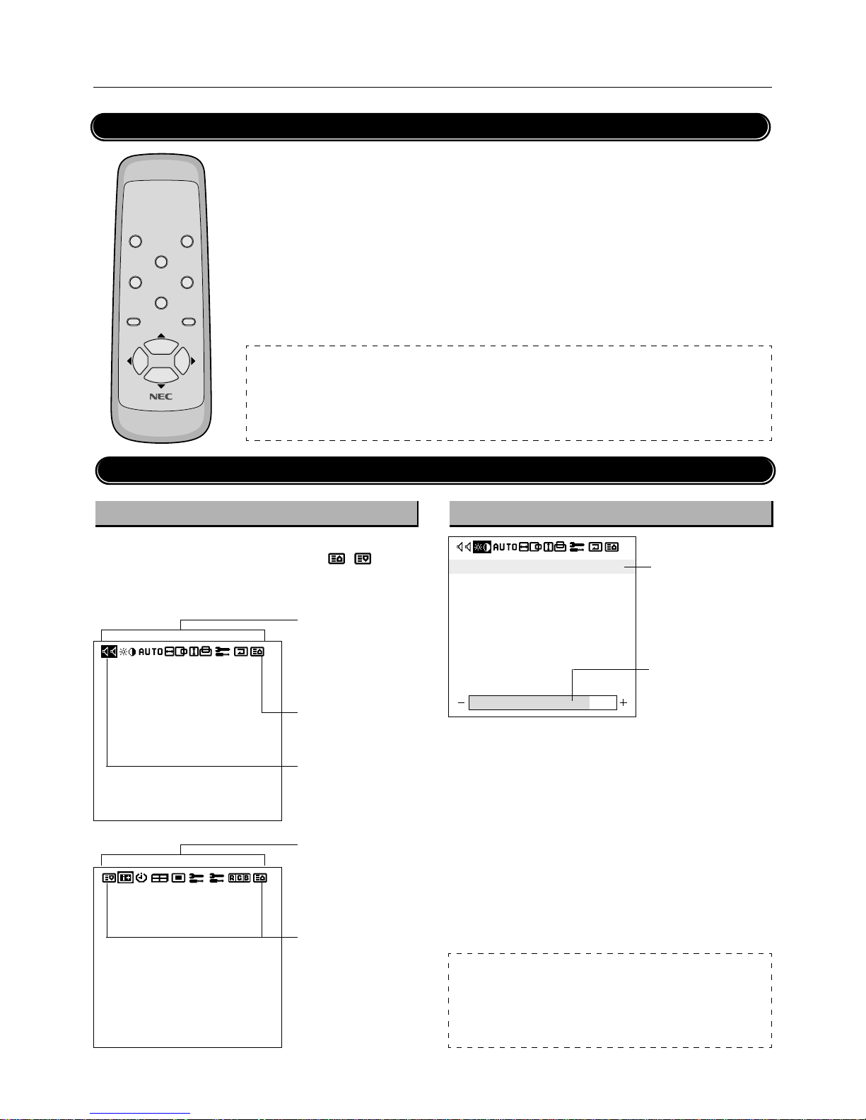
E-22
†
PLASMA MONITOR
Menu Operations
Buttons Used in Menu Operations
● PROCEED button
Displays the main menu.
Determine the selection or set details in the main
menu and proceed to the next step.
● EXIT button
Turns off the main menu.
Press during display of the sub menu to return
to the main menu.
POWER OFF
RGB 1
POWER ON
RGB 3
RGB 2/DVD/HD
VI DEO
EXI T
PROCEED
POSITION/CONTROL
RP-102
● POSITION/CONTROL buttons
▲ button : Moves the cursor up.
▼ button : Moves the cursor down.
button : Moves the cursor left.
Press during display of the sub menu (setting/
adjustment screen) to select setting items and
also to decrease the adjustment value.
button : Moves the cursor right.
Press during display of the sub menu (setting/
adjustment screen) to select setting items and
also to increase the adjustment value.
NOTE:
CONFIG MENU
Press and hold the POSITION/CONTROL ▲ button and the PROCEED button simultaneously for 3 seconds or longer to
display the CONFIG MENU. This only works for the CONFIG MENU out of the various on-screen menus (OSM).
The menu screen of the CONFIG MENU does not contain icons that indicate menu items; however, operation is the same as
with other screens.
Operation of the Menu Screen
Main menu Sub menu
The main menu comprises 2 pages (screens). Place the cursor on
icon
or and use the POSITION/CONTROL / button to
change the page. (Set [OSD MODE] to [PRO] on the configuration
menu before performing other operations.)
VOLUME
BALANCE
MUTE
INPUT1
INPUT2
: OFF
: VIDEO
: RGB1
● Items of the main menu
are displayed as icons.
See Pages E-20 and 21
for details.
● Displays the next page.
● Place the cursor here
and press the button
to display the next page.
SOURCE INFO.
RGB1
H-FREQ.
V-FREQ.
H-POL.
V-POL.
31.5kHz
60.0Hz
NEG
POS
● Items of the main menu
are displayed as icons.
See Pages E-20 and 21
for details.
● Displays the previous
page.
BRIGHTNESS
CONTRAST
SHARPNESS
COLOR
TINT
● Cursor
● Indication of the
adjustment value.
NOTE:
Auto Memory
The setting value is automatically stored after the adjustment. Note that
setting values will not be automatically stored in the following circumstances.
* The power cable is disconnected from the outlet during the setting.
* There is a power outage during the setting.
Page 94
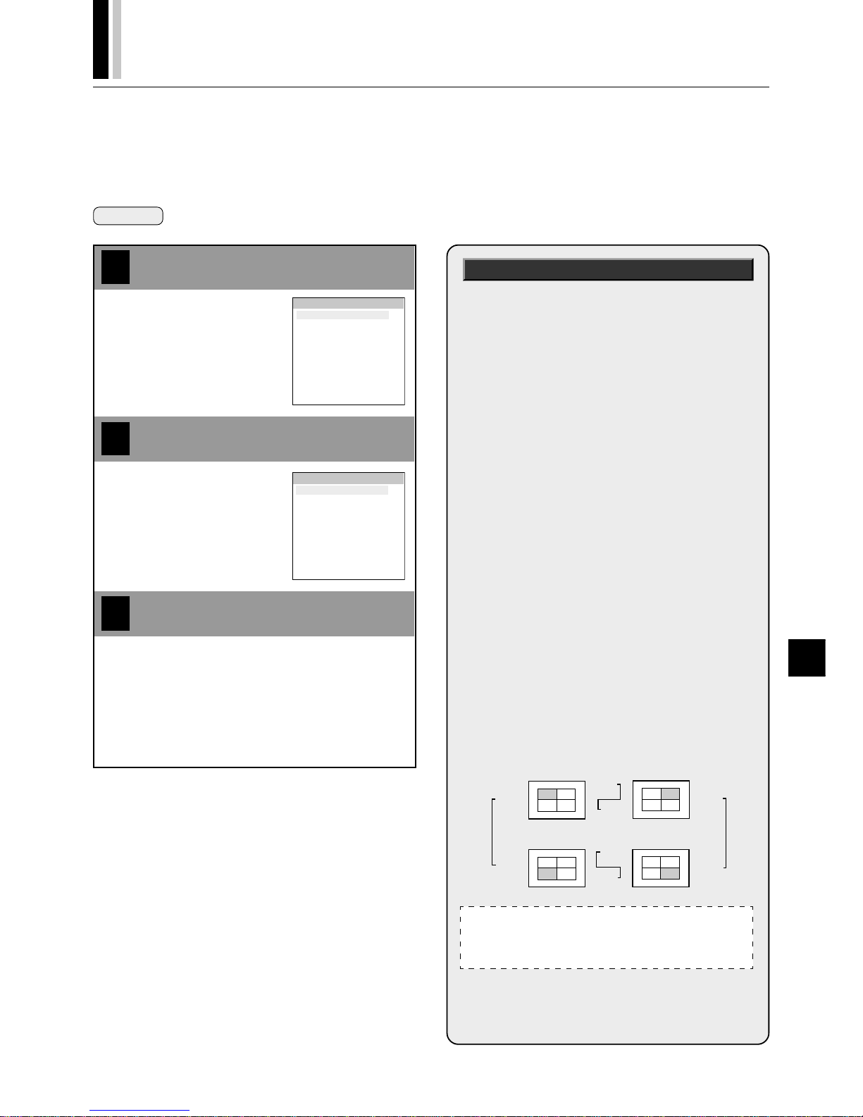
PLASMA MONITOR
† E-23
Configuration Menu (CONFIG MENU)
This menu sets the main menu, display of adjustment details, remote control, sync, and the brightness of the multiple system.
1
Align the cursor with the desired item
2
3
Move the cursor up and down with
the POSITION/CONTROL ▲▼
buttons.
OSD DISPLAY :NORMAL
OSD MODE :BASIC
WIRELESS REMOTE
CONTROL :ON
SYNC MODE :AUTO
PLE LINK :OFF
ALL RESET
CONFIG MENU
OSD DISPLAY :KEY
OSD MODE :BASIC
WIRELESS REMOTE
CONTROL :ON
SYNC MODE :AUTO
PLE LINK :OFF
ALL RESET
CONFIG MENU
Press the EXIT button one time to return to the config menu.
One further press removes the menu.
Adjust with the POSITION/CONTROL
buttons
Press the EXIT button 2 times
Adjustment Items
■ OSD DISPLAY
[NORMAL] :
Displays the menu screen and adjustment details.
[KEY] :
Displays the adjustment details for only input switching and direct adjustments.
[OFF] :
No display of any menu screens or adjustment details.
■ OSD MODE
[BASIC] :
Allows only the first page of the main menu to be displayed.
[PRO] :
Allows Pages 1 and 2 of the main menu to be displayed.
■ WIRELESS REMOTE CONTROL
[ON] : Enables remote control wireless transmission.
[OFF] : Disables remote control wireless transmission.
* This is normally [ON]. Set [OFF] to avoid unwanted control
from other remote controls.
■ SYNC MODE
[AUTO] : Automatically detects separate sync signals,
green sync signal (i.e., sync-on-green), and
composite sync signal.
[GSYNC] : Automatically detects green sync signal (i.e.,
sync-on-green).
[CSYNC] : Automatically detects composite sync signal.
■ PLE LINK
[ON] : Sets a uniform screen brightness for each
screen in a 4-screen multiple system.
[OFF] : Sets the screen brightness for each of the
screens in a 4-screen or multiple system to their
respective brightness.
* When this function is set [ON], connect four plasma moni-
tors with the remote control cable (included with the optional remote control) in the order of the position numbers
for 4-screen multiple system. See the drawing below.
Preparation Simultaneously press and hold the POSITION/CONTROL ▲ button and the PROCEED button for 3 seconds or longer
to display the menu screen.
Note:
Please use the control panel of the main unit at this time since
operation with the remote control will not be enabled with this
arrangement.
REMOTE
IN
REMOTE
IN
REMOTE
OUT
REMOTE
OUT
REMOTE
IN
REMOTE
OUT
REMOTE
OUT
REMOTE
IN
No.1
No.2
No.3No.4
No.1
No.2
No.3No.4
No.1
No.2
No.3No.4
No.1
No.2
No.3No.4
Monitor Monitor
Monitor Monitor
■ ALL RESET
Align the cursor and then press the PROCEED button to return all adjustments and settings of CONFIG MENU to the
factory default values.
Page 95
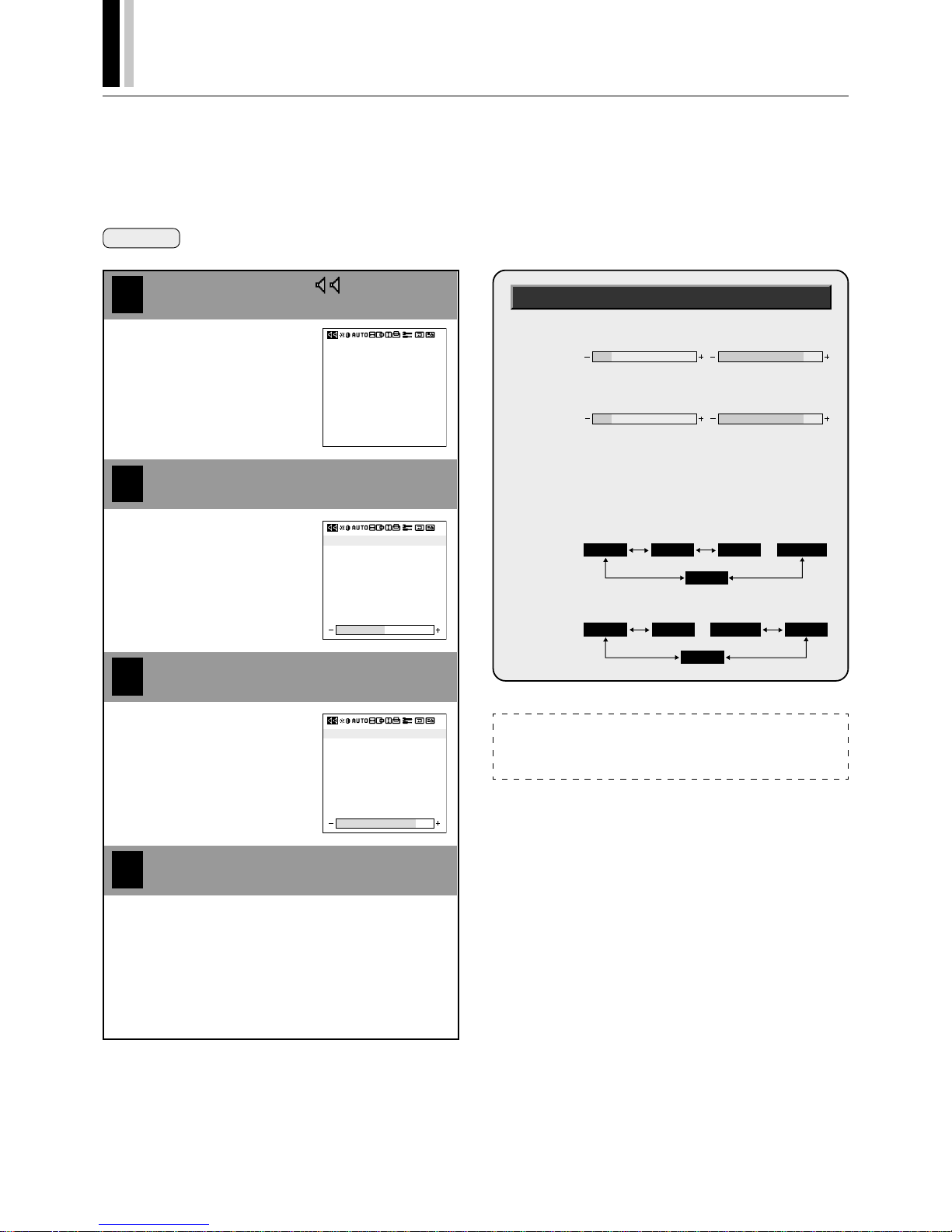
E-24
†
PLASMA MONITOR
4
Audio Settings (SOUND)
This menu sets the volume, balance, mute, and selection of input.
Note that only sound of the currently displayed signal is output.
Preparation Press the PROCEED button to display the main menu.
1
Align the cursor with
2
3
Move the cursor left and right with
the POSITION/CONTROL
buttons.
VOLUME
BALANCE
MUTE
INPUT1
INPUT2
: OFF
: VIDEO
: RGB1
VOLUME
BALANCE
MUTE
INPUT1
INPUT2
: OFF
: VIDEO
: RGB1
VOLUME
BALANCE
MUTE
INPUT1
INPUT2
: OFF
: VIDEO
: RGB1
Align the cursor with the desired item
Adjust with the POSITION/CONTROL
buttons
Move the cursor up and down with
the POSITION/CONTROL ▲▼
buttons.
Press the EXIT button 2 times
Press the EXIT button one time to return to the main menu.
One further press removes the menu.
Adjustment Screen
[VOLUME] : Adjusts the volume
[BALANCE]: Adjusts the left and right volume balance.
[MUTE] : Switches off the sound (temporarily)
[OFF] : There is sound.
[ON] : Sound is switched off.
[INPUT 1] : Each press serves to advance the audio input
of AUDIO IN 1 by one step.
[INPUT 2] : Each press serves to advance the audio input
of AUDIO IN 2 by one step.
RGB 3
DVD/HD
VIDEO
RGB 1
RGB 2
or
VIDEO
RGB 3
RGB 1
DVD/HD
RGB 2
or
Decrease Increase
Left side becomes stronger Right side becomes stronger
Note:
Adjustments of [VOLUME], [BALANCE], [MUTE] will be stored in memory
for each input (VIDEO, RGB 1-3, DVD/HD, and SCART). To change these
settings, first display the source of which audio input you wish to adjust.
Page 96
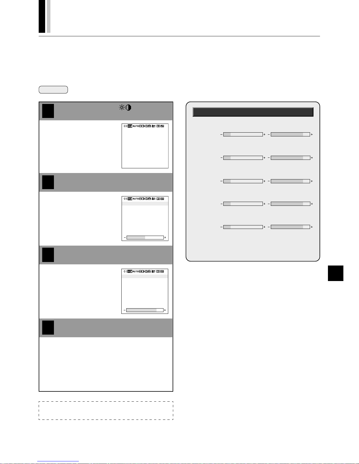
PLASMA MONITOR
† E-25
Picture Adjustments (VISUAL CONTROL)
This menu adjusts the brightness, contrast, sharpness, color, and tint.
Preparation Press the PROCEED button to display the main menu.
4
1
Align the cursor with
2
3
Move the cursor left and right with
the POSITION/CONTROL
buttons.
BRIGHTNESS
CONTRAST
SHARPNESS
COLOR
TINT
BRIGHTNESS
CONTRAST
SHARPNESS
COLOR
TINT
BRIGHTNESS
CONTRAST
SHARPNESS
COLOR
TINT
Align the cursor with the desired item
Adjust with the POSITION/CONTROL
buttons
Move the cursor up and down with
the POSITION/CONTROL ▲▼
buttons.
Press the EXIT button 2 times
Press the EXIT button one time to return to the main menu.
One further press removes the menu.
Adjustment Screen
[BRIGHTNESS]
: Adjusts the brightness of the screen.
[CONTRAST]
: Adjusts the contrast of the image.
[SHARPNESS]
: Adjusts the sharpness of the image.
[COLOR] : Adjusts the color saturation
[TINT] : Adjusts the tint.
* These adjustments will not be available when
the color system setting is set to [PAL] or
[SECAM].
Darker Brighter
Fainter Denser
Note:
Only the [BRIGHTNESS] and [CONTRAST] adjustments are available with
the RGB input screen.
Softer More distinct
Less saturated More saturated
Tinted toward red Tinted toward green
Page 97
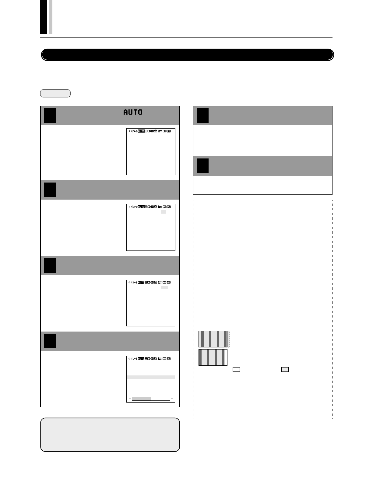
E-26
†
PLASMA MONITOR
Auto Picture/Wide Screen Settings (AUTO PICTURE)
There is normally no need to adjust the clock frequency or clock phase when [AUTO PICTURE] is set to [ON]; however, when automatic
adjustment cannot adjust the picture properly, a manual adjustment should be made.
Make an adjustment when a signal is newly input, and when vertical lines appear and the image appears blurred.
Preparation Press the PROCEED button to display the main menu.
4
1
Align the cursor with
2
3
Move the cursor left and right with
the POSITION/CONTROL
buttons.
AUTO PICTURE
INPUT MODE
RGB MODE
WIDE MODE : FULL
: ON
: 4X3
: STILL
AUTO PICTURE
INPUT MODE
RGB MODE
WIDE MODE : FULL
: ON
: 4X3
: STILL
: OFF
: 4X3
: STILL
AUTO PICTURE
INPUT MODE
RGB MODE
PICTURE ADJ
FINE PICTURE
WIDE MODE : FULL
Align the cursor with AUTO PICTURE
Select OFF with the POSITION/CON-
TROL
buttons
Move the cursor up and down with
the POSITION/CONTROL ▲▼
buttons.
Align the cursor with the desired item
Move the cursor up and down
with the POSITION/CONTROL
▲▼ buttons.
Clock Frequency/Clock Phase Adjustment, and RGB Mode Adjustment (AUTO PICTURE)
5
6
Adjust with the POSITION/CONTROL
buttons
Press the EXIT button 2 times
: OFF
: 4X3
: STILL
AUTO PICTURE
INPUT MODE
RGB MODE
PICTURE ADJ
FINE PICTURE
WIDE MODE : FULL
INPUT MODE:
[4x3], [16x9] and [16x9!] are used in the discrimination and switching of
the input signal. See "INPUT MODE" of "Signal Identification For Raster
Preset" (P.E-62) when making the setting.
[RGB MODE] : Sets the mode (i.e., moving picture/still
picture mode) to suit the input signal
[PICTURE ADJ] : Adjusts the clock frequency
[FINE PICTURE] : Adjusts the clock phase
Press the EXIT button one time to return to the main menu.
One further press removes the menu.
Note:
■
AUTO PICTURE
Adjustment of [H-POSITION] and [V-POSITION] is not available
when [AUTO PICTURE] is set to [ON] at the time of RGB signal input.
When adjustment is required, set [AUTO PICTURE] to [OFF].
When the displayed image is small with respect to the original number of
horizontal pixels (including instances where the display area, i.e., lit pixels is small), the picture may take up to 6 seconds to be displayed.
■
RGB MODE
[MOTION] : Set when a moving picture source is connected such as a
scan converter.
[STILL] : Set when displaying a personal computer screen.
[DTV] : Set when viewing a source such as a digital broadcast using
RGB input.
■
Clock Frequency Adjustment (PICTURE ADJ)
This adjusts the width of the image with respect to the screen.
Adjustment is performed with a dot unit signal.
Adjust to the position at which vertical flickering disappears.
■
Clock Phase Adjustment (FINE PICTURE)
Adjust for minimal screen noise, flicker, and color infidelity.
First adjust the clock frequency, then perform the clock phase adjustment.
* Clock frequency and clock phase adjustments are not available at the
time of VIDEO (and S-VIDEO) input.
When the width of the image signal is wider than the
monitor screen, adjust the size with the POSITION/
CONTROL button.
When the width of the image signal is narrower than
the monitor screen, adjust the size with the POSITION/
CONTROL button.
: Monitor screen size
: Image signal size
Page 98
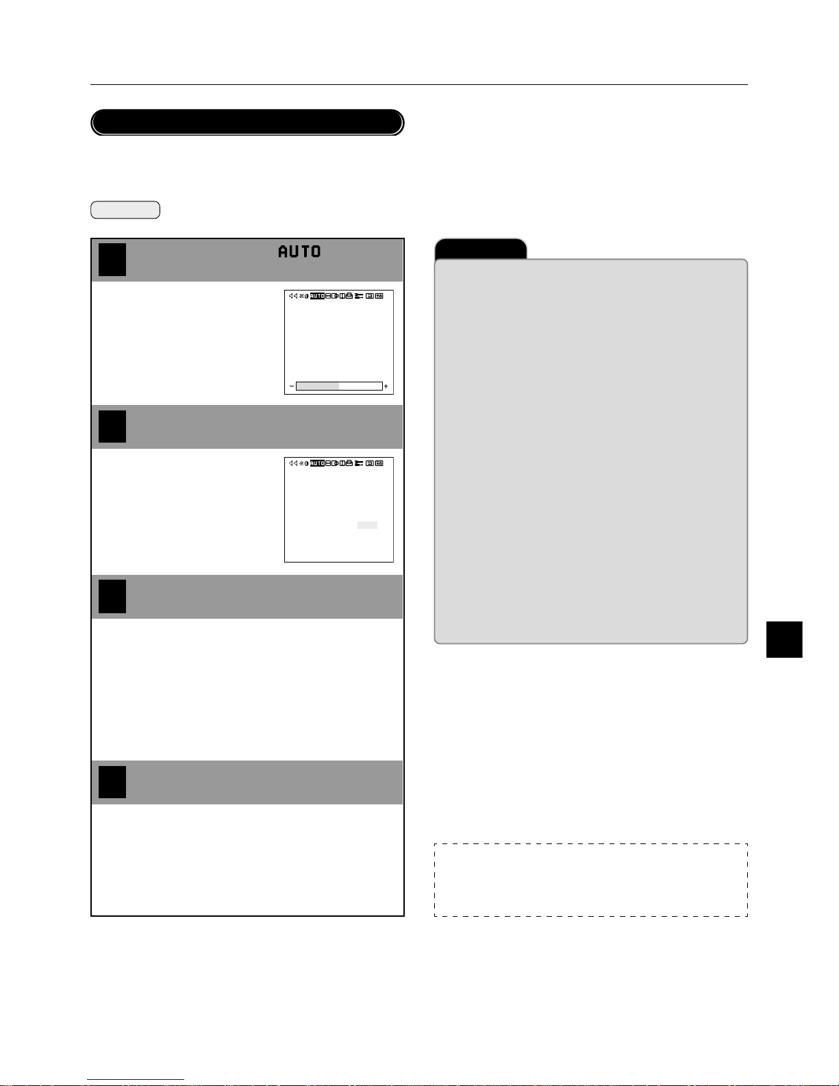
PLASMA MONITOR
† E-27
4
1
2
3
Important
Auto Picture/Wide Screen Settings (AUTO PICTURE)
This sets the wide screen display (to NORMAL, FULL, ZOOM, or STADIUM).
Preparation Press the PROCEED button to display the main menu.
Align the cursor with
Move the cursor left and right with
the POSITION/CONTROL
buttons.
Align the cursor with AUTO PICTURE
Set the wide screen mode with the
POSITION/CONTROL
buttons
Move the cursor up and down with
the POSITION/CONTROL ▲▼
buttons.
Press the EXIT button 2 times
Press the EXIT button one time to return to the main menu.
One further press removes the menu.
Wide Screen Setting (WIDE MODE)
[NORMAL] : This is the normal screen size (4:3).
[FULL] : Enlarges the picture left and right.
[ZOOM] : Enlarges the picture left to right and top to bot-
tom in the same proportion.
[STADIUM] : Enlarges each of the left to right and top to bot-
tom values in their respective ratios.
* Only [NORMAL] and [FULL] settings are available with an
RGB input screen.
■
Precautions in Normal Mode
There are marked differences in brightness between the display portions
and non-display portions (where there is no image) in [NORMAL] mode
which result in image burn-in due to the strong contrast. In view of this,
the following settings are strongly recommended.
Note that image burn-in will still occur, though somewhat later, even after
making these settings and that burn-in cannot be suppressed. The monitor should be used in [FULL] mode as much as possible.
1. Perform gray level settings to narrow the differences in brightness be-
tween display and non-display portions of the image. (See P.E-43)
2. Weaken the image adjustment contrast and brightness. (See P.E-25)
3. Perform the Long Life settings. (P.E-42)
■
Copyright
Please note that using this monitor for the purpose of commercial gain or
the attraction of public attention in a venue such as a coffee shop or hotel
and employing compression or expansion of the screen image with a
wide screen setting (of FULL, ZOOM, or STADIUM) raises concern about
the infringement of copyright rights which are protected by copyright law.
■
Screen Size and the Original Image
This monitor is equipped with a wide variety of wide screen settings. Selection of a screen size that differs with the image aspect ratio (i.e., the
ratio of the vertical and horizontal dimensions of the screen) of the video
tape or other software will produce differences in appearance with respect to the original image. Please keep this point in mind when selecting
the screen size.
Note:
■
Supported Input Signals and Resolutions
Please see Page E-62 for information about the input signals and resolutions that this monitor supports.
: OFF
: 4X3
: STILL
AUTO PICTURE
INPUT MODE
RGB MODE
WIDE MODE : FULL
: OFF
: 4X3
: STILL
AUTO PICTURE
INPUT MODE
RGB MODE
WIDE MODE : FULL
Page 99
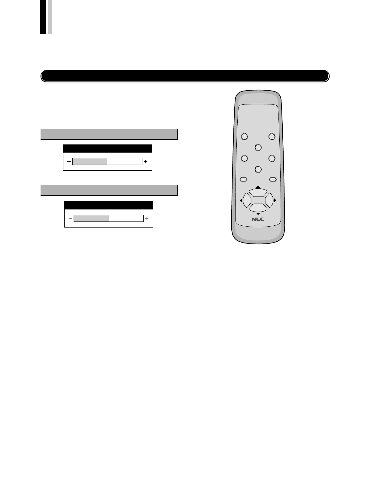
E-28
†
PLASMA MONITOR
Horizontal/Vertical Position Adjustments (H-POSITION and V-POSITION)
Horizontal and vertical position adjustments are available in 2 types. “Direct adjustment” makes adjustments simply by pressing the
buttons of the remote control and “Menu control adjustments” are made via menu display.
Direct Adjustment
Adjusts the horizontal position and the vertical position of the
screen.
A press of the button displays the adjustment screen. Release
your finger from the button after the adjustment is made. The display will disappear about 3 seconds later and the adjustment details will be stored.
Move left Move right
▼ Move down Move up ▲
Vertical position adjustment (POSITION/CONTROL
▲▼
)
Horizontal position adjustment (POSITION/CONTROL
)
POWER OFF
RGB 1
POWER ON
RGB 3
RGB 2/DVD/HD
VI DEO
EXI T
PROCEED
POSITION/CONTROL
RP-102
H-POSITION
V-POSITION
Page 100
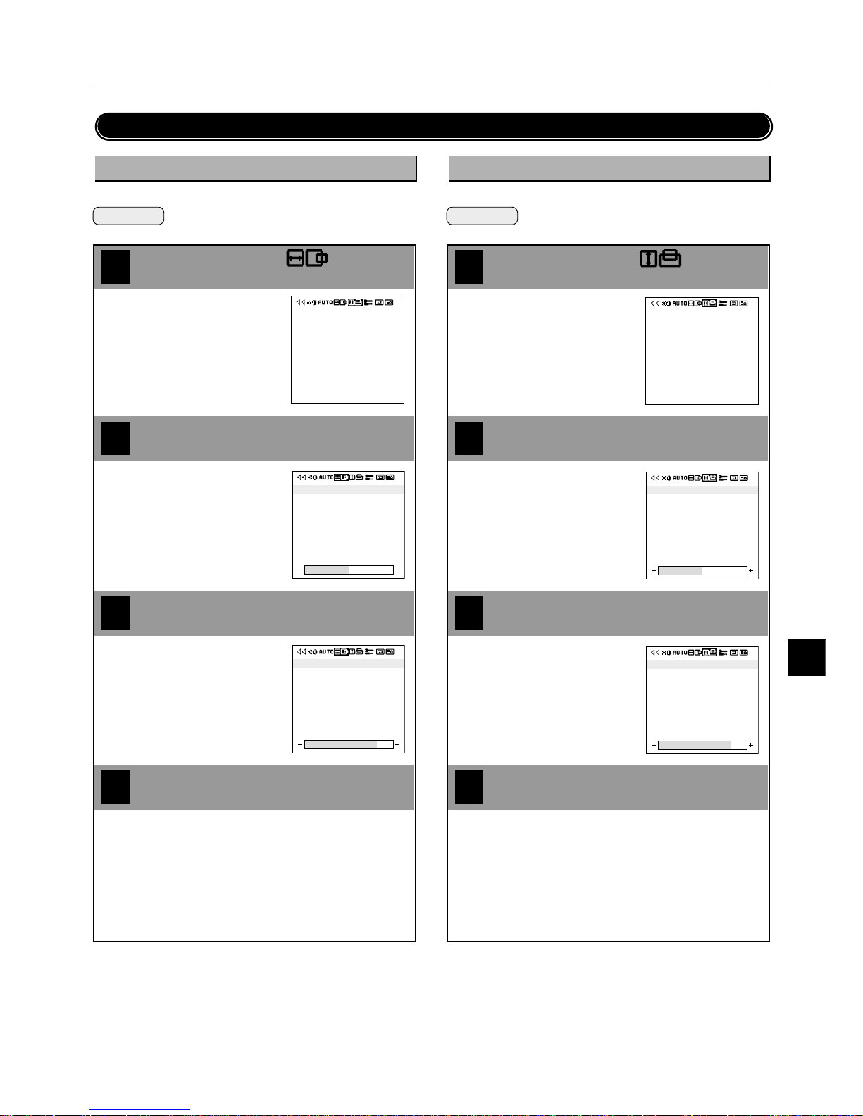
PLASMA MONITOR
† E-29
3
3
Horizontal/Vertical Position Adjustments (H-POSITION and V-POSITION)
Menu Adjustments
Adjusts the horizontal position and width of the screen.
Preparation Press the PROCEED button to display the main
menu.
4
1
Align the cursor with
2
Move the cursor left and right with
the POSITION/CONTROL
buttons.
• H-WIDTH is adjustable only in
multiple mode.
Align the cursor with the desired item
Move the cursor up and down with
the POSITION/CONTROL ▲▼
buttons.
Press the EXIT button 2 times
Press the EXIT button one time to return to the main menu.
One further press removes the menu.
Vertical position adjustment
Adjusts the vertical position and height of the screen.
Preparation Press the PROCEED button to display the main
menu.
4
1
Align the cursor with
2
Move the cursor left and right with
the POSITION/CONTROL
buttons.
• V-HEIGHT is adjustable only in
multiple mode.
V-POSITION
V-HEIGHT
V-POSITION
V-HEIGHT
Align the cursor with the desired item
Move the cursor up and down with
the POSITION/CONTROL ▲▼
buttons.
Press the EXIT button 2 times
Press the EXIT button one time to return to the main menu.
One further press removes the menu.
V-POSITION
V-HEIGHT
Horizontal position adjustment
H-POSITION
H-WIDTH
H-POSITION
H-WIDTH
V-POSITION
V-HEIGHT
Adjust with the POSITION/CONTROL
buttons
Adjust with the POSITION/CONTROL
buttons
 Loading...