

Page 1
PlasmaSync Plasma Monitor
PlasmaSync 42XM3
PX-42XM3G
Model Information
Modell-Informationen
Informations modèle
Información del modelo
Informazioni sul modello
нформация о модели
Page 2
E-1
Specifications
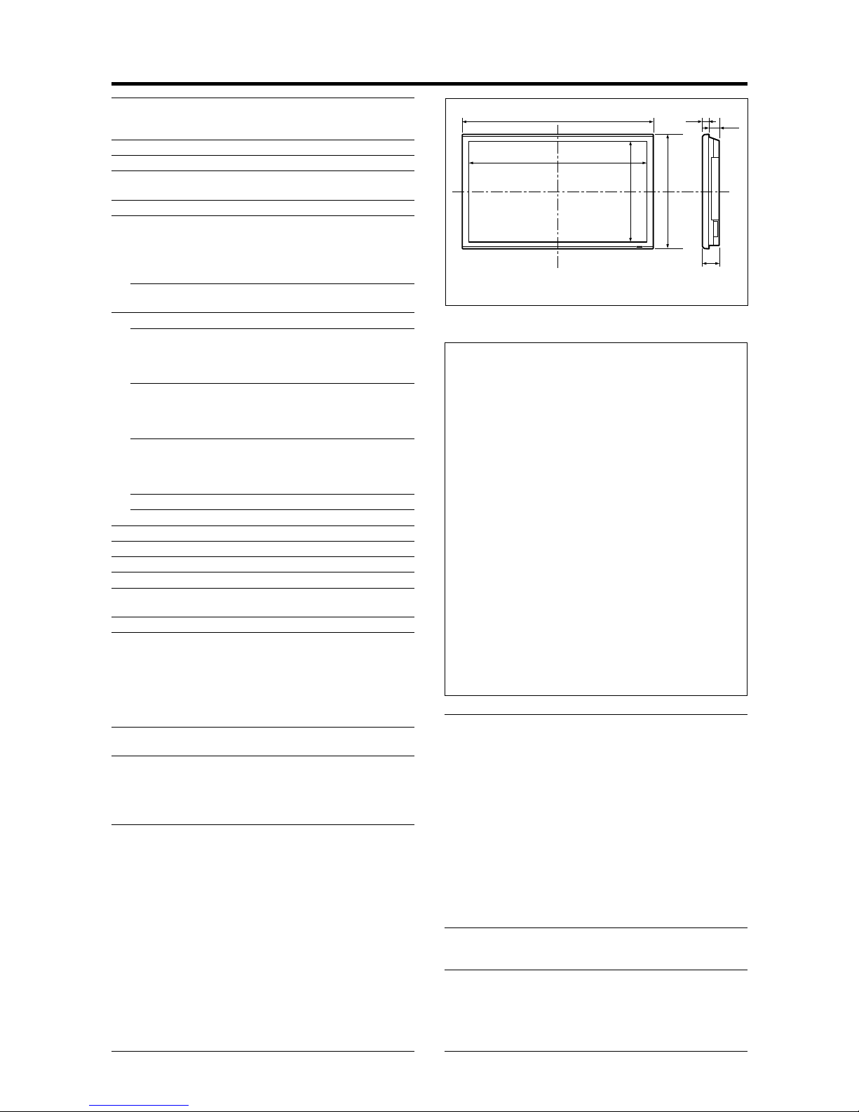
Screen Size 918(H)518(V) mm
36.1"(H)20.4"(V) inches
diagonal 42"
Aspect Ratio 16 : 9
Resolution 1024(H)768(V) pixels
Pixel Pitch 0.897(H)0.675(V) mm
0.036"(H)0.027"(V) inches
Color Processing 4,096 steps, 68.7 billion colors
Signals
Synchronization Range Horizontal : 15.5 to 110 kHz
(automatic : step scan)
Vertical : 50.0 to 120.0 Hz
(automatic : step scan)
Input Signals RGB, NTSC (3.58/4.43), P AL (B,G,M,N),
P AL60, SECAM, HD*
1
, DVD*1 , DTV*
1
Input Terminals (VIDEO1 and RGB1 can also be used as OUTPUT terminals)
RGB
Visual 1 (Analog) mini D-sub 15-pin1
Visual 2 (Analog) BNC (R, G, B, H/CS, V)1*
2
Visual 3 (Digital) DVI-D 24-pin1*
3
Video
Visual 1 BNC1
Visual 2 RCA-pin1
Visual 3 S-Video: DIN 4-pin1
DVD/HD/DTV
Visual 1 RCA-pin (Y, PB[CB], PR[CR])1*
1
Visual 2 BNC (Y, PB[CB], PR[CR])1*
1, *2
Visual 3 DVI-D 24-pin1*
3
Audio Stereo RCA3(Selectable)
External Control D-sub 9-pin1(RS-232C)
Sound output 8W+8W at 6 ohm
Power Supply AC100-240V 50/60Hz
Current Rating 5.2A (maximum)
Power Consumption 305W (typical)
Dimensions 1018 (W)610 (H)89(D) mm
40 (W)24 (H)3.5 (D) inches
Weight 29.5 kg / 65.0 lbs (without stand)
Environmental Considerations
Operating Temperature 0°C to 40°C / 32°F to 104°F
Humidity 20 to 80% (no condensation)
Altitude 0 to 2800 m / 0 to 9180 feet
Storage Temperature -10°C to 50°C / 14°F to 122°F
Humidity 10 to 90% (no condensation)
Altitude 0 to 3000 m / 0 to 9840 feet
Front Panel User Controls Power on/off, Input source select,
Volume up/down, OSM control
Remote Control Functions
Power on/off, Input source select, OSM
control,Volume up/down, Cursor (UP,
DOWN,LEFT, RIGHT), Pointer , Zoom up/
down, Off timer, Wireless/ Wired remote
control
OSM Functions
Picture (Contrast/Brightness/Sharpness/Color/Tint/
Picture mode/Noise reduction/Color temperature/
White balance/Gamma/Low tone/Color tune), Audio
(Bass/Treble/Balance/Audio input), Image Adjust
(Aspect mode/V-Position /H-Position/V-Height /HWidth/Auto Picture/Fine picture/Picture adjustment),
Option1 (OSM/BNC Input/D-Sub Input/RGB Select/
HD Select/Input Skip/All Reset), Option2 (Power
management/Cinema mode/Long life [PLE, Orbiter,
Inverse, White, Screen wiper, Soft focus]/Gray level/
S1/S2/DVI Set up), Option3 (Timer/Power on mode/
Control lock/IR Remote/Loop out/ID number/Video
wall [Divider, Position, Disp. mode, Auto ID, Image
adjust, Power on delay, PLE link, T imer]), Advanced
OSM, Language*, Color system, Source information
*English, German, French, Italian, Spanish, Swedish,
Chinese, Russian
The features and specifications may be subject to change without
notice.
*1HD/DVD/DTV input signals supported on this
system
480P (60 Hz) 480I (60 Hz)
525P (60 Hz) 525I (60 Hz)
576P (50 Hz) 576I (50 Hz)
625P (50 Hz) 625I (50 Hz)
720P (60 Hz) 1035I (60 Hz)
1080I (50 Hz) 1080I (60 Hz)
*
2
The 5-BNC connectors are used as RGB/PC2 and
HD/DVD2 input. Select one of them under “BNC
INPUT”.
*
3
Compatable with HDCP.
Supported Signals
• 640480P @ 59.94/60Hz • 19201080I @ 50Hz
• 1280720P @ 59.94/60Hz • 720576P @ 50Hz
• 19201080I @ 59.94/60Hz • 1440 (720)576P @ 50Hz
• 720480P @ 59.94/60Hz
• 1440 (720)480I @ 59.94/60Hz
Note: In some cases a signal on the plasma monitor may not be displayed
properly. The problem may be an inconsistency with standards from
the source equipment (DVD, Set-top box, etc...). If you do experience
such a problem please contact your dealer and also the manufacturer of
the source equipment.
Units are in mm
(inch)
89
(3.5")
35
(1.38")
54
(2.13")
1018 (40")
610 (24")
918 (36.1")
518 (20.4")
Other Features Motion compensated 3D Scan Converter (NTSC,
P AL, 480I, 576I, 525I, 625I, 1035I, 1080I), 2-3
pull down Converter (NTSC, 480I, 525I, 1035I,
1080I (60Hz)), 2-2 pull down Converter (P AL,
576I, 625I, NTSC, 480I, 525I), Digital Zoom
Function (100-900% Selectable), Video Wall 4-25
multi screen, Self Diagnosis, Image Burn
reduction tools (PLE LOCK1~3, INVERSE,
WHITE, ORBITER (Auto1,2/Manual), SCREEN
WIPER), Color T emperature select (high/mid/mid
low/low, user has 4 memories), Control lock
(Except power SW), Auto Picture, Input Skip,
Color Tune, Low Tone (3 mode), Auto ID,
Programmable Timer , Gamma Correction
(4 mode), Loop through interface, Plug and play
(DDC1, DDC2b, RGB3: DDC2b only)
Accessories Remote control with two AAA batteries, Power
cord, Manuals, Safety metal fittings, Ferrite cores,
Bands, Cable clamps
Regulations
Meets EMC Directive
(EN55022 Class A, EN55024, EN61000-3-2,
EN61000-3-3)
Meets Low Voltage Directive
(EN60950-1, IEC60950-1, SEMKO Approved)
Meets AS/NZS CISPR 22:2002 Class A
Bezel color is gray.
For the operation of your plasma monitor,
refer to “Operation Manual”.
Page 3
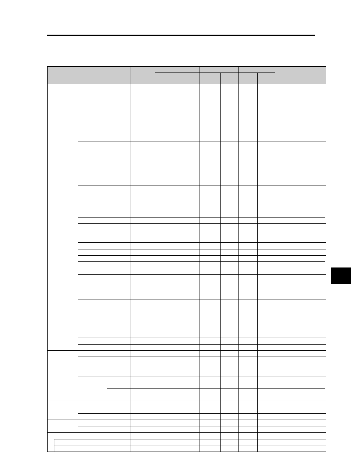
Table of Signals Supported
Supported resolution
• When the screen mode is NORMAL, each signal is converted to a 768 dots768 lines signal. (Except for *
2, *4
)
• When the screen mode is FULL, each signal is converted to a 1024 dots768 lines signal.
Computer input signals supported by this system
E-2
Screen mode
Dots lines
640400
640480
848480
852480*
1
800600
1024768
1152864
1280768
1280768*
9
1280800*
9
1280854*
9
1360765
1360768
1376768
12801024
16801050*
9
16001200
19201200*
9
19201200RB
*
9
640480
832624
1024768
1152870
1440900*
9
12801024
12801024
1152900
12801024
1024768
12801024
768576
640480
Vertical
frequency
(Hz)
70.1
59.9
72.8
75.0
85.0
100.4
120.4
60.0
60.0
56.3
60.3
72.2
75.0
85.1
99.8
120.0
60.0
70.1
75.0
85.0
100.6
75.0
56.2
59.8
69.8
60.0
60.0
60.0
60.0
59.9
60.0
75.0
85.0
100.1
60.0
60.0
65.0
70.0
75.0
85.0
60.0
60.0
66.7
74.6
74.9
75.1
60.0
60.0
71.2
72.0
66.0
76.0
76.1
60.0
60.0
50.0
59.9
Horizontal
frequency
(kHz)
31.5
31.5
37.9
37.5
43.3
51.1
61.3
31.0
31.7
35.2
37.9
48.1
46.9
53.7
63.0
75.7
48.4
56.5
60.0
68.7
80.5
67.5
45.1
48.0
56.0
49.7
53.1
47.7
47.7
48.3
64.0
80.0
91.1
108.5
65.3
75.0
81.3
87.5
93.8
106.3
74.6
74.0
35.0
49.7
60.2
68.7
56.0
64.6
75.1
78.1
61.8
71.7
81.1
49.7
63.9
31.4
31.5
NORMAL
(4:3)
YES*
2
YES
YES
YES
YES
YES
YES
– –
– –
YES
YES
YES
YES
YES
YES
YES
YES
YES
YES
YES
YES
YES
– –
– –
– –
– –
– –
– –
– –
– –
YES*
4
YES*
4
YES*
4
YES*
4
– –
YES
YES
YES
YES
YES
– –
– –
YES*
3
YES
YES
YES
– –
YES*
4
YES*
4
YES*
4
YES
YES
YES*
4
YES
YES*
4
YES*
7
YES*
7
FULL
(16:9)
YES
YES
YES
YES
YES
YES
YES
YES
YES
YES
YES
YES
YES
YES
YES
YES
YES*
3
YES*
3
YES*
3
YES*
3
YES*
3
YES
YES
YES
YES
YES
YES
YES
YES
YES
YES
YES
YES
YES
YES
YES
YES
YES
YES
YES
YES
YES
YES
YES
YES*
3
YES
YES
YES
YES
YES
YES
YES
YES
YES*
3
YES
YES*
7
YES*
7
RGB
select*
5
– –
STILL
– –
STILL
– –
– –
– –
WIDE2
WIDE1
STILL
STILL
– –
– –
– –
– –
– –
STILL
– –
STILL
– –
– –
STILL
WIDE1
WIDE3
WIDE1
WIDE1
WIDE2
WIDE1
WIDE1
WIDE2
STILL
– –
– –
– –
WIDE4
– –
– –
– –
– –
– –
WIDE2
WIDE3
– –
– –
WIDE1
WIDE1
– –
– –
– –
– –
– –
– –
– –
– –
– –
– –
MOTION
Apple
Macintosh*
6, *8
Horizontal
NEG
NEG
NEG
NEG
NEG
NEG
NEG
POS
NEG
POS
POS
POS
POS
POS
POS
POS
NEG
NEG
POS
POS
NEG
POS
POS
POS
NEG
NEG
NEG
POS
POS
NEG
POS
POS
POS
POS
NEG
POS
POS
POS
POS
POS
NEG
NEG
Sync on G
Sync on G
Sync on G
Sync on G
NEG
NEG
NEG
– –
C Sync
C Sync
C Sync
– –
– –
NEG
NEG
Work Station
(EWS4800)
*
8
Work Station (HP)
*
8
Work Station
(SUN)
*
8
Work Station
(SGI)
IDC-3000G
Signal Type
IBM PC/AT
compatible
computers*
8
Vertical
NEG
NEG
NEG
NEG
NEG
NEG
NEG
POS
NEG
POS
POS
POS
POS
POS
POS
POS
NEG
NEG
POS
POS
NEG
POS
POS
NEG
POS
NEG
NEG
POS
POS
POS
POS
POS
POS
POS
NEG
POS
POS
POS
POS
POS
NEG
NEG
Sync on G
Sync on G
Sync on G
Sync on G
NEG
NEG
NEG
– –
C Sync
C Sync
C Sync
– –
– –
NEG
NEG
Sync Polarity
Presence
Horizontal
YES
YES
YES
YES
YES
YES
YES
YES
YES
YES
YES
YES
YES
YES
YES
YES
YES
YES
YES
YES
YES
YES
YES
YES
YES
YES
YES
YES
YES
YES
YES
YES
YES
YES
YES
YES
YES
YES
YES
YES
YES
YES
– –
– –
– –
– –
YES
YES
YES
– –
– –
– –
– –
– –
– –
YES
YES
Vertical
YES
YES
YES
YES
YES
YES
YES
YES
YES
YES
YES
YES
YES
YES
YES
YES
YES
YES
YES
YES
YES
YES
YES
YES
YES
YES
YES
YES
YES
YES
YES
YES
YES
YES
YES
YES
YES
YES
YES
YES
YES
YES
– –
– –
– –
– –
YES
YES
YES
– –
– –
– –
– –
– –
– –
YES
YES
PAL625P
NTSC525P
Model
DVI
NO
YES
YES
YES
YES
YES
YES
YES
YES
YES
YES
YES
YES
YES
YES
YES
YES
YES
YES
YES
YES
YES
NO
YES
YES
YES
YES
NO
YES
YES
YES
YES
YES
NO
YES
YES
NO
NO
NO
NO
– –
YES
NO
NO
NO
NO
YES
YES
YES
YES
YES
YES
YES
YES
YES
NO
NO
Memory
4
5
7
8
9
41
42
19
17
11
12
13
14
15
43
44
24
25
26
27
45
51
52
80
66
21
37
22
22
53
29
30
40
47
38
54
55
56
57
58
81
88
6
16
28
39
89
29
48
59
60
61
30
62
29
31
32
Page 4
E-3
Warning
Apparatus shall not be exposed to dripping or splashing and
that no objects filled with liquids, such as vases, shall be
placed on apparatus.
T o reduce the risk of fire or electric shock, do not expose this
apparatus to rain or moisture.
This is a Class A product. In a domestic environment, this
product may cause radio interference in which case the user
may be required to take adequate measures.
Important Information
*1 Only when using a graphic accelerator board that is capable of displaying 852480.
*2 Display only 640 lines with the screen center of the vertical orientation located at the center.
*3 The picture is displayed in the original resolution. The picture will be compressed for other signals.
*4 Aspect ratio is 5:4. This signal is converted to a 720 dots768 lines signal.
*5 Normally the RGB select mode suite for the input signals is set automatically . If the picture is not displayed properly , set the RGB mode
prepared for the input signals listed in the table above.
*6 To connect the monitor to Macintosh computer, use the monitor adapter (D-Sub 15-pin) to your computer's video port.
*7 Other screen modes (ZOOM and ST ADIUM) are available as well.
*8 When viewing a moving picture at a vertical frequency greater than 65Hz, the picture may sometimes be unstable (jumpy). If this occurs,
please set the refresh rate of the external equipment to 60Hz.
To view 480I@60Hz (480 interlaced lines, 60Hz refresh rate) or 576I@50Hz (567 interlaced lines, 50Hz refresh rate) when sync polarity
is “Sync on Green”, set “RGB SELECT” to “MOTION”.
*9 CVT standard compliant.
NOTE:
• While the input signals comply with the resolution listed in the table above, you may have to adjust the position and size of the
picture or the fine pictur e because of errors in synchronization of your computer.
• This monitor has a resolution of 1024 dots768 lines. It is recommended that the input signal should be XGA, wide XGA, or
equivalent.
• With digital input some signals are not accepted.
• The sync may be disturbed when a nonstandard signal other than the afor ementioned is input.
• If you are connecting a composite sync signal, use the HD terminal.
What is HDCP/HDCP technology?
HDCP is an acronym for High-bandwidth Digital Content Protection. High bandwidth Digital Content Protection (HDCP) is a system for
preventing illegal copying of video data sent over a Digital V isual Interface (DVI).
If you are unable to view material via the DVI input, this does not necessarily mean the PDP is not functioning properly . W ith the implementation
of HDCP , there may be cases in which certain content is protected with HDCP and might not be displayed due to the decision/intention of the
HDCP community (Digital Content Protection, LLC).
•“IBM PC/AT” and “XGA” are registered trademarks of International Business Machines, Inc. of the United States.
•“Apple Macintosh” is a registered trademark of Apple Computer, Inc. of the United States.
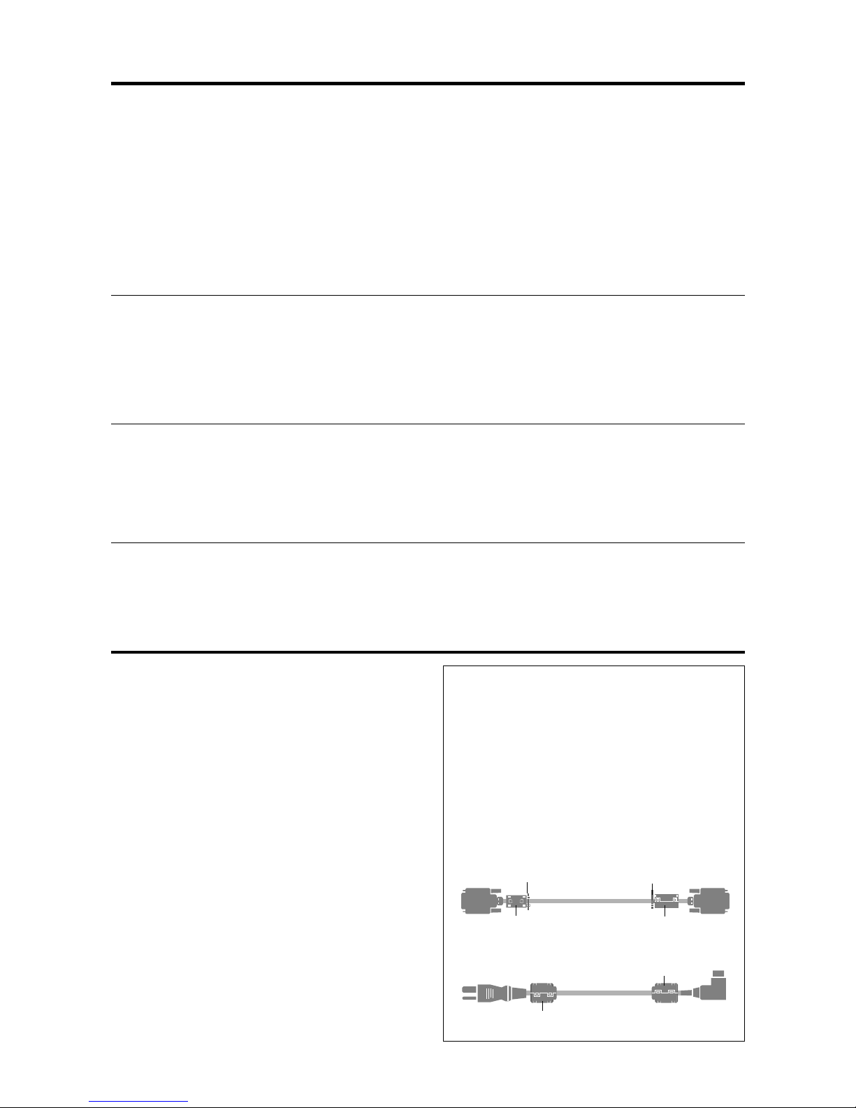
NOTE:
When you connect a computer to this monitor, use an RGB
cable including the ferrite core on both ends of the cable.
And regarding DVI and power cable, attach the supplied
ferrite cores. If you do not do this, this monitor will not
conform to mandatory CE or C-Tick standards.
Set the ferrite cores on both ends of the DVI cable (not
supplied), and both ends of the power cable (supplied).
Close the lid tightly until the clamps click.
Use the band to fasten the ferrite core (supplied) to the
DVI cable.
DVI cab le (not supplied)
core (small)
core (small)
Connector
band
band
Power cable (supplied)
core (large)
core (large)
Page 5

ENGLISH
DEUTSCH
FRANÇAIS
ESPAÑOL
ITALIANO
Operation Manual
(Enhanced split screen Model)
For the specifications of your plasma
monitor, refer to “Model Information”.
У
Page 6
E-2
Precautions
Please read this manual carefully before using your plasma monitor
and keep the manual handy for future reference.
CAUTION
RISK OF ELECTRIC SHOCK
DO NOT OPEN
CAUTION:
TO REDUCE THE RISK OF ELECTRIC
SHOCK, DO NOT REMOVE COVER. NO
USER-SERVICEABLE PARTS INSIDE.
REFER SERVICING TO QUALIFIED SERVICE
PERSONNEL.
This symbol warns the user that uninsulated
voltage within the unit may have sufficient
magnitude to cause electric shock. Therefore, it
is dangerous to make any kind of contact with
any part inside of this unit.
This symbol alerts the user that important
literature concerning the operation and
maintenance of this unit has been included.
Therefore, it should be read carefully in order to
avoid any problems.
WARNING
TO PREVENT FIRE OR SHOCK HAZARDS, DO NOT EXPOSE
THIS UNIT TO RAIN OR MOISTURE. ALSO DO NOT USE
THIS UNIT’S POLARIZED PLUG WITH AN EXTENSION CORD
RECEPTACLE OR OTHER OUTLETS, UNLESS THE
PRONGS CAN BE FULLY INSERTED. REFRAIN FROM
OPENING THE CABINET AS THERE ARE HIGH-VOLTAGE
COMPONENTS INSIDE. REFER SERVICING TO QUALIFIED
SERVICE PERSONNEL.
Warnings and Safety Precaution
This plasma monitor is designed and manufactured to provide
long, trouble-free service. No maintenance other than cleaning
is required. Please see the section “Plasma monitor cleaning
procedure” on the next page.
The plasma display panel consists of fine picture elements
(cells) with more than 99.99 percent active cells. There may
be some cells that do not produce light or remain lit.
For operating safety and to avoid damage to the unit, read
carefully and observe the following instructions.
To avoid shock and fire hazards:
1. Provide adequate space for ventilation to avoid internal heat
build-up. Do not cover rear vents or install the unit in a closed
cabinet or shelves.
If you install the unit in an enclosure, make sure there is adequate
space at the top of the unit to allow hot air to rise and escape. If
the monitor becomes too hot, the overheat protector will be
activated and the monitor will be turned off. If this happens,
turn off the power to the monitor and unplug the power cord. If
the room where the monitor is installed is particularly hot, move
the monitor to a cooler location, and wait for 60 minutes to cool
the monitor. If the problem persists, contact your dealer for
service.
2. Do not use this unit’s polarized plug with extension cords or
outlets unless the prongs can be completely inserted.
3. Do not expose the unit to water or moisture.
4. A void damage to the power cord, and do not attempt to modify
the power cord.
5. Unplug the power cord during electrical storms or if the unit
will not be used over a long period.
6. Do not open the cabinet which has potentially dangerous high
voltage components inside. If the unit is damaged in this way
the warranty will be void. Moreover, there is a serious risk of
electric shock.
7. Do not attempt to service or repair the unit. The manufacturer is
not liable for any bodily harm or damage caused if unqualified
persons attempt service or open the back cover. Refer all service
to authorized Service Centers.
To avoid damage and prolong operating life:
1. Use only with 100-240V 50/60Hz AC power supply . Continued
operation at line voltages greater than 100-240 Volts AC will
shorten the life of the unit, and might even cause a fire hazard.
2. Handle the unit carefully when installing it and do not drop.
3. Set the unit away from heat, excessive dust, and direct sunlight.
4. Protect the inside of the unit from liquids and small metal objects.
In case of accident, unplug the power cord and have it serviced
by an authorized Service Center.
5. Do not hit or scratch the panel surface as this causes flaws on
the surface of the screen.
6. For correct installation and mounting it is strongly recommended
to use a trained, authorized dealer.
7. As is the case with any phosphor-based display (like a CRT
monitor, for example) light output will gradually decrease over
the life of a Plasma Display Panel.
8. To avoid sulfurization it is strongly recommended not to place
the unit in a dressing room in a public bath or hot spring bath.
9. Do not use in a moving vehicle, as the unit could drop or topple
over and cause injuries.
10.Do not place the unit on its side, upside-down or with the screen
facing up or down, to avoid combustion or electric shock.
Plasma monitor cleaning procedure:
1. Use a soft dry cloth to clean the front panel and bezel area. Never
use solvents such as alcohol or thinner to clean these surfaces.
2. Clean plasma ventilation areas with a vacuum cleaner with a
soft brush nozzle attachment.
3. To ensure proper ventilation, cleaning of the ventilation areas
must be carried out monthly. More frequent cleaning may be
necessary depending on the environment in which the plasma
monitor is installed.
Recommendations to avoid or minimize phosphor burn-in:
Like all phosphor-based display devices and all other gas plasma
displays, plasma monitors can be susceptible to phosphor burn under
certain circumstances. Certain operating conditions, such as the
continuous display of a static image over a prolonged period of
time, can result in phosphor burn if proper precautions are not taken.
To protect your investment in this plasma monitor , please adhere to
the following guidelines and recommendations for minimizing the
occurrence of image burn:
* Always enable and use your computer’s screen saver function
during use with a computer input source.
* Display a moving image whenever possible.
* Change the position of the menu display from time to time.
* Always power down the monitor when you are finished using it.
If the plasma monitor is in long term use or continuous operation
take the following measures to reduce the likelihood of phosphor
burn:
* Lower the Brightness and Contrast levels as much as possible
without impairing image readability.
* Display an image with many colors and color gradations (i.e.
photographic or photo-realistic images).
* Create image content with minimal contrast between light and
dark areas, for example white characters on black backgrounds.
Use complementary or pastel color whenever possible.
* Avoid displaying images with few colors and distinct, sharply
defined borders between colors.
* Note: Burn-in is not covered by the warranty.
Contact your dealer for other recommended procedures that will
best suit your particular application needs.
Important Information
Page 7
E-3
Contents
Contents of the Package
䡺 Plasma monitor
䡺 Power cord
䡺 Remote control with two AAA Batteries
䡺 Manuals (Model Information and Operation)
䡺 Safety metal fittings*
䡺 Ferrite cores, bands
䡺 Cable clamps
* Contents will differ according to the model.
* These are fittings for fastening the unit to a wall to prevent
tipping due to external shock when using the stand
(optional). Fasten the safety fittings to the holes in the
back of the monitor using the safety fitting mount screws
(see page E-4).
Options
• Wall mount unit
• Ceiling mount unit
• Tilt mount unit
• Stand
• Attachable speakers
Installation .................................................... E-4
Ventilation Requirements for enclosure mounting ....... E-4
How to use the safety metal fittings and the screws for
safety metal fittings ............................................. E-4
Creating a video wall ............................................ E-5
Cable Management............................................... E-5
Caution on when the plasma monitor is installed vertically ....
E-6
How to use the remote control................................. E-6
Battery Installation and Replacement ....................... E-6
Using the wired remote control mode ...................... E-6
Operating Range ...................................................... E-6
Handling the remote control..................................... E-6
Part Names and Function ................................ E-7
Front View ........................................................... E-7
Rear View/ Terminal Board .................................... E-8
Remote Control ..................................................... E-9
Basic Operations ........................................... E-10
POWER ..............................................................E-10
To turn the unit ON and OFF: ................................ E-10
VOLUME ............................................................E-10
To adjust the sound volume:................................... E-10
MUTE .................................................................E-10
To mute the audio: ................................................. E-10
DISPLAY ..............................................................E-10
To check the settings:............................................. E-10
DIGITAL ZOOM ...................................................E-10
AUTO ADJUST .................................................... E-10
To adjust the size or quality of the picture
automatically:...................................................... E-10
OFF TIMER ..........................................................E-10
To set the of f timer:................................................ E-10
To check the remaining time: ................................. E-10
To cancel the off timer: .......................................... E-10
WIDE Operations ........................................... E-11
Wide Screen Operation (manual) .......................... E-11
When viewing videos or digital video discs ........... E-11
Wide Screen Operation with Computer Signals .......E-12
When “PICTURE SIZE” is set to “OFF”............... E-12
SPLIT SCREEN Operations ............................... E-13
Showing a couple of pictures on the screen at the
same time ........................................................E-13
Operations in the Side-by-side mode...................... E-13
Operations in the Picture-in-picture mode .............. E-14
Selecting the input signals to be displayed ............. E-14
Zooming up pictures .............................................. E-14
Adjusting the OSM controls................................... E-14
OSM (On Screen Menu) Controls ..................... E-15
Menu Operations ................................................. E-15
Menu Tree ...........................................................E-16
Picture Settings Menu............................................E-18
Adjusting the picture.............................................. E-18
Setting the picture mode according to the brightness
of the room .......................................................... E-18
Reducing noise in the picture ................................. E-18
Setting the color temperature ................................. E-18
Adjusting the color to the desired level .................. E-19
Changing the Gamma Curve .................................. E-19
Making the Low T one adjustments ........................ E-19
Adjusting the colors ............................................... E-19
Audio Settings Menu ............................................ E-20
Adjusting the treble, bass and left/right balance and
audio input select................................................. E-20
Setting the allocation of the audio connectors ........ E-20
Image Adjust Settings Menu .................................. E-20
Adjusting the Position, Size, Fine Picture, Picture Adj ....
E-20
Option1 Settings Menu .........................................E-21
Setting the on-screen menu .................................... E-21
Setting the BNC connectors ................................... E-21
Setting the RGB1 connector................................... E-21
Setting a computer image to the correct RGB select
screen .................................................................. E-21
Setting high definition images to the suitable screen size .....
E-22
Setting the Input Skip............................................. E-22
Resetting to the default values................................ E-22
Option2 Settings Menu .........................................E-23
Setting the power management for computer images ......
E-23
POWER/ST ANDBY indicator ............................... E-23
Setting the picture to suit the movie ....................... E-23
Reducing burn-in of the screen .............................. E-23
Setting the gray level for the sides of the screen ..... E-25
Setting the screen size for S1/S2 video input .......... E-25
Setting the picture size for RGB input signals ........ E-26
Setting the signal and black level for DVI signal.... E-26
Option3 Settings Menu .........................................E-26
Using the timer ...................................................... E-26
Setting the power on mode..................................... E-28
Enabling/disabling the front panel controls ............ E-28
Enabling/disabling remote control wireless
transmission ........................................................ E-28
Loop Out setting .................................................... E-28
ID number setting .................................................. E-29
Video Wall setting.................................................. E-29
Option4 Settings Menu .........................................E-32
Erasing the sub screen image when there is no input
signal................................................................... E-32
Displaying the entire image during DIGIT AL ZOOM
operations ............................................................ E-32
Displaying still images in the sub screen ................ E-32
Switching the input source quickly ........................ E-33
Advanced OSM Settings Menu ..............................E-33
Setting the menu mode .......................................... E-33
Language Settings Menu .......................................E-33
Setting the language for the menus......................... E-33
Color System Settings Menu ..................................E-34
Setting the video signal format............................... E-34
Source Information Menu ......................................E-34
Checking the frequencies, polarities of input signals,
and resolution ...................................................... E-34
External Control ...........................................E-35
Application .........................................................E-35
Connections ........................................................E-35
Type of connector: D-Sub 9-pin male .................... E-35
Communication Parameters ................................... E-35
External Control Codes (Reference) ........................ E-35
Pin Assignments ...........................................E-35
mini D-Sub 15-pin connector (Analog) ...................E-35
DVI-D 24-pin connector (Digital) ............................E-35
Troubleshooting ............................................ E-36
Page 8

E-4
50mm (2")
50
mm
(2") 50
mm
(2")
Wall
Wall
50mm (2")
50mm (2")
You can attach your optional mounts or stand to the plasma monitor in one of the following two ways:
* While it is upright. (See Drawing A)
* As it is laid down with the screen face down (See Drawing B). Lay the protective sheet, which was wrapped around the
monitor when it was packaged, beneath the screen surface so as not to scratch the screen face.
* Do not touch or hold the screen face when carrying the unit.
• This device cannot be installed on its own. Be sure to use a stand or original mounting unit. (Wall
mount unit, Stand, etc.)
* See page E-3.
• For correct installation and mounting it is strongly recommended to use a trained, authorized
dealer.
Failure to follow correct mounting procedures could result in damage to the equipment or injury
to the installer.
Product warranty does not cover damage caused by improper installation.
Drawing B
Drawing A
When installing or carrying, use
the handles attached to the upper
back of the display.
Ventilation Requirements for
enclosure mounting
T o allow heat to disperse, leave space between surrounding
objects as shown on the diagram below when installing.
Installation
How to use the safety metal fittings
and the screws for safety metal
fittings
These are fittings for fastening the unit to a wall to prevent
tipping due to external shock when using the stand
(optional). Fasten the safety fittings to the holes in the
back of the monitor using the safety fitting mount screws.
* Safety metal fittings will differ according to the model.
Screw hole
Wall
Table Top
Safty metal fittings
Screw for Safty metal
fittings
Metal chain
(Not supplied)
Screw or Hook etc.
(Not supplied)
Page 9
E-5
Note:
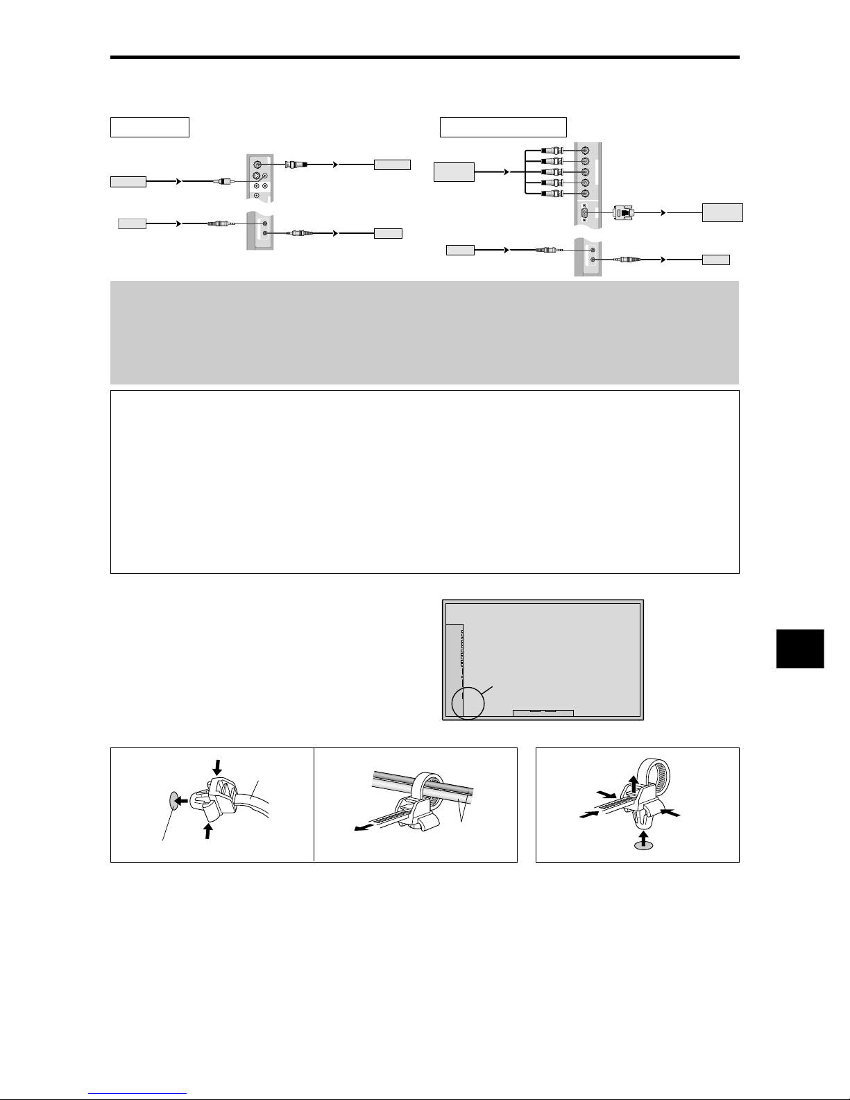
1. The VIDEO1 and RGB1 terminals can be used for either INPUT or OUTPUT.
When LOOP OUT is ON, do not connect an OUTPUT signal from another unit, that will place an extraordinary
load on the other unit and may damage it.
2. LOOP OUT can not be turned ON while signals are input to the RGB1 terminal.
3. LOOP OUT can be turned ON while signals are input to the RGB1 terminal if the POWER is switched ON.
Information
• To loop signals out to another plasma display, set the LOOP OUT to ON.
• To create a video wall, set the VIDEO WALL menu items properly.
• To connect monitors, please use a 1~2m (3.3~6.6 feet) BNC cable (any commercially available cable).
• If the image quality is poor, do not use the monitor’s out terminal. Use a distribution amplifier (any commercially
available distribution amplifier) to connect the split signals to the respective monitor INPUT terminals.
• Being used as a video wall function, maximaly 4-screen is rough-standard with lower than 1024768, 60Hz
signal.
• A distribution amplifier is particularly recommended when using 9-screen and over video wall.
• From the second monitor onward, connections require a BNC-RCA conversion cable or connector, a mini D-Sub
15 pin cable-BNC (5) cable or a conversion connector.
Creating a video wall
With built-in matrix display capability, you can create a 4-25 video wall.
• Connect signal cables and remote cables as shown below.
Video signal RGB/DVD/HD signal
VIDEO
(
IN/OUT
)
VIDEO
1
VIDEO
2
VIDEO
3
AUDIO
1
DVD
1
R
(
MONO
)
L
Y
IN OUT
REMOTE
BNC connector
RCA phono plug
OUT
VIDEO Signal
IN
IN
OUT
Remote
control
VIDEO Signal
Remote
control
RGB
2
/
DVD
2
/
HD
2
RGB
1
R/
VD
G/ B/
HD
(
IN/OUT
)
Cr/Pr Y Cb/Pb
IN OUT
REMOTE
BNC connector
RGB signal/
DVD/HD signal
IN
OUT
IN
OUT
Remote
control
RGB signal/
DVD/HD signal
Remote
control
Cable Management
Using the cable-clamps provided with the plasma display,
bundle at the back of the unit the signal and audio cables
connected to the display.
Back of the unit
mounting holes
To attach To detach
clamp
mounting hole
cables
1. 2.
Page 10
E-6
Approx.
7m/23ft
MENU/ENTER
INPUT SELECT
DOWN UP LEFT/-RIGHT/+/EXIT
VOLUME
MENU/ENTER
INPUT SELECT
DOWN UP LEFT/
-
RIGHT/
+
/EXIT
VOLUME
OPTION1
EXIT
OSM
BNC INPUT
D-SUB INPUT
RGB SELECT
HD SELECT
INPUT SKIP
ALL RESET
: RGB
: RGB
: AUTO
: 1080B
: OFF
: OFF
1024768
SEL.
RETURN
MENU/ENTER
OK
Top side
Bottom side
90°
Caution on when the plasma monitor is installed vertically
• Use the optional unit. Contact your store of purchase when installing.
• Rotate 90° clockwise as seen from the front when installing.
• After installing, check with the NEC logo mark as seen
from the front.
• Be sure to set “OSM ANGLE” to “V” when using.
* Failure to heed the above cautions may lead to malfunction.
How to use the remote control
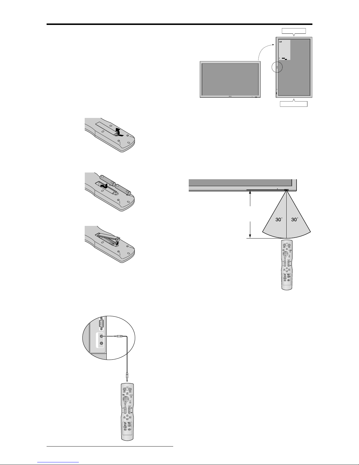
Battery Installation and Replacement
Insert the 2 “AAA” batteries, making sure to set them in
with the proper polarity.
1.Press and open the cover.
2.Align the batteries according to the (+) and (–) indication
inside the case.
3.Replace the cover.
Handling the remote control
• Do not drop or mishandle the remote control.
• Do not get the remote control wet. If the remote control
gets wet, wipe it dry immediately.
• Avoid heat and humidity.
• When not using the remote control for a long period,
remove the batteries.
• Do not use new and old batteries together, or use different
types together.
• Do not take apart the batteries, heat them, or throw them
into a fire.
• When using the remote control in the wireless condition,
be sure to unplug the remote cable from the REMOTE
IN terminal on the monitor.
Using the wired remote control mode
Connect the remote cable* to the remote control’s remote
jack and the “REMOTE IN” terminal on the monitor.
When the cable is connected, the mode automatically
switches to wired remote control. When the wired remote
control mode is used, the remote control can be operated
even if no batteries are loaded.
* The 1/8 Stereo Mini cable must be purchased separately .
External Control
IN OUT
REMOTE
Remote Control
Cable*
To Remote Jack
Operating Range
* Use the remote control within a distance of about 7 m/
23ft. from the front of the monitor’s remote control sensor
and at horizontal and vertical angles of up to approximately
30°.
* The remote control operation may not function if the
monitor’s remote control sensor is exposed to direct
sunlight or strong artificial light, or if there is an obstacle
between the sensor and the remote control.
Page 11
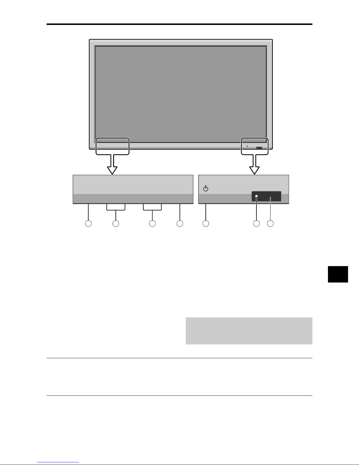
E-7
q Power
Turns the monitor’s power on and off.
w Remote sensor window
Receives the signals from the remote control.
e POWER/STANDBY indicator
When the power is on ............................. Lights green.
When the power is in the standby mode ... Lights red.
r INPUT SELECT / EXIT
Switches the input.
The available inputs depend on the settings of “BNC
INPUT”, “D-SUB INPUT”, “RGB SELECT” and
“DVI SET UP”.
Functions as the EXIT buttons in the On-Screen Menu
(OSM) mode.
Front View
MENU/ENTER
INPUT SELECT
DOWN UP LEFT/-RIGHT/+/EXIT
VOLUME
MENU/ENTER
INPUT SELECT
DOWN UP LEFT/-RIGHT/+/EXIT
VOLUME
4
5
6
7
1
3
2
t LEFT/– and RIGHT/+
Enlarges or reduces the image. Functions as the
CURSOR (
/ ) buttons in the On-Screen Menu
(OSM) mode.
y VOLUME DOWN and UP
Adjusts the volume. Functions as the CURSOR (▲/
▼) buttons in the On-Screen Menu (OSM) mode.
u MENU/ENTER
Sets the On-Screen Menu (OSM) mode and displays
the main menu.
WARNING
The Power on/off switch does not disconnect the plasma
display completely from the supply mains.
Part Names and Function
Note:
This plasma monitor has the capasity to display images when connected to European DVD players with a SCART
output signal, which is RGB with composite sync.
Your dealer can supply a special SCART cable, which will enable you to use the RGB with composite sync signal.
To obtain the special cable as well as for further information, please contact your dealer.
Please refer to page E-21 for selection of the corr ect mode in the on-screen manager.
Page 12
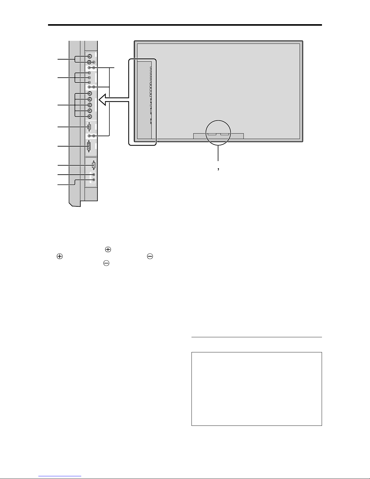
E-8
A AC IN
Connect the included power cord here.
B EXT SPEAKER L and R
Connect speakers (optional) here. Maintain the correct
polarity. Connect the
(positive) speaker wire to the
EXT SPEAKER terminal and the (negative)
speaker wire to the
EXT SPEAKER terminal on
both LEFT and RIGHT channels.
Please refer to your speaker’s owner’s manual.
C VIDEO1, 2, 3 (BNC, RCA, S-Video)
Connect VCR’s, DVD’s or Video Cameras, etc. here.
VIDEO1 can be used for Input or Output (see page E-
5).
D AUDIO1, AUDIO2, AUDIO3
These are audio input terminals.
The input is selectable. Set which video image to allot
them from the audio menu screen.
E DVD1 / HD1
Connect DVD’s, High Definition or Laser Discs, etc.
here.
F RGB2/ DVD2/ HD2
RGB2: Y ou can connect an analog RGB signal
and the syncronization signal.
DVD2/ HD2: You can connect DVDs, High
Definition sources, Laser Discs, etc.
here.
This input can be set for use with an
RGB or component source (see page
E-21)
G RGB1 (mini D-Sub 15pin)
Connect an analog RGB signal from a computer, etc.
here. This input can be used for Input or Output. (see
page E-5)
H RGB3
(DVI 24pin)
Connect a digital signal (TMDS) from a source with a
DVI output.
This input can be set for use with an RGB/PC3 (see
page E-26)
I EXTERNAL CONTROL
This terminal is used when operating and controlling
the monitor externally (by RS-232C).
J REMOTE IN
Connect the remote cable* to the remote control’s
remote jack to obtain wired remote control.
K REMOTE OUT
Connect the remote cable* to the REMOTE IN jack of
the other display monitor to obtain wired remote
control.
* The 1/8 Stereo Mini cable must be purchased separately .
Information
• For Y/CB/Cr, connect to the DVD1 or DVD2
terminals.
• For SCART, this unit provides three ways to connect:
· SCART1: Connect R/G/B to the DVD2 terminals
and composite sync. to the HD terminal.
· SCART2: Connect R/G/B to the DVD2 terminals
and composite sync. to the VIDEO1 terminal.
· SCART3: Connect R/G/B + composite sync. to the
RGB1 terminal.
VIDEO
VIDEO
1
VIDEO
2
VIDEO
3
AUDIO
1
DVD
1
/
HD
1
R
(
MONO
)
L
YCb/PbCr/Pr
RGB
2
/
DVD
2
/
HD
2
RGB
1
R/
VD
G/ B/
HD
DVI
(
Digital RGB
)
AUDIO
2
R
(
MONO
)
L
AUDIO
3
R
(
MONO
)
L
Cr/Pr Y Cb/Pb
RGB
3
AB
D
C
E
F
G
H
I
J
K
External Control
IN OUT
REMOTE
Rear View/ Terminal Board
Page 13
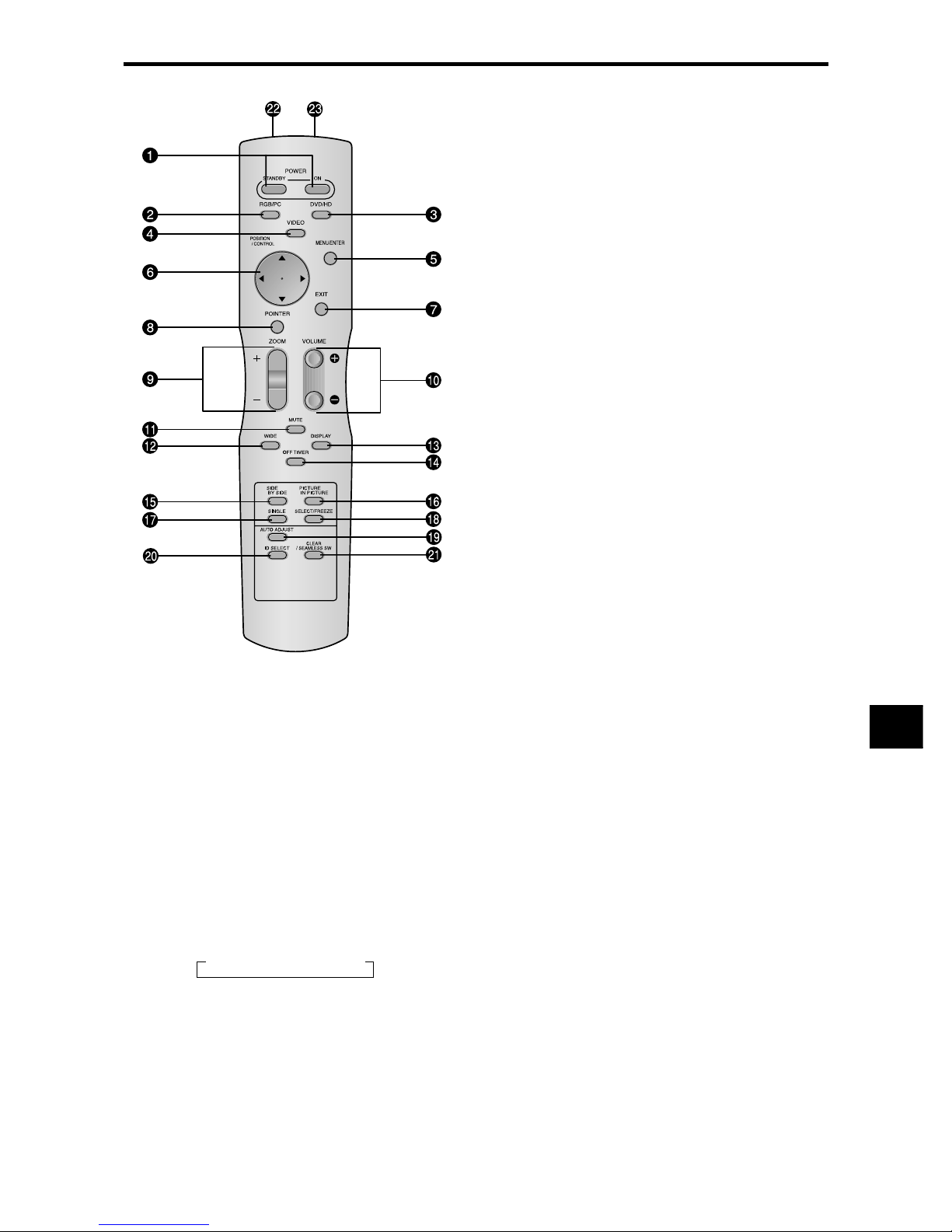
E-9
q POWER ON/STANDBY
Switches the power on/standby.
(This does not operate when POWER/STANDBY
indicator of the main unit is off.)
w RGB/PC
Press this button to select RGB/PC as the source.
RGB/PC can also be selected using the INPUT
SELECT button on the monitor.
e DVD / HD
Press this button to select DVD/HD as the source.
DVD/HD can also be selected using the INPUT
SELECT button on the monitor.
r VIDEO
Press this button to select VIDEO as the source.
VIDEO can also be selected using the INPUT SELECT
button on the monitor.
t MENU/ENTER
Press this button to access the OSM controls.
Press this button during the display of the main menu
to go to the sub menu.
y CURSOR (▲ / ▼ /
/ )
Use these buttons to select items or settings and to
adjust settings or switch the display patterns.
u EXIT
Press this button to exit the OSM controls in the main
menu. Press this button during the display of the sub
menu to return to the previous menu.
i POINTER
Press this button to display the pointer.
o ZOOM (+ /–)
Enlarges or reduces the image.
!0 VOLUME (+ /–)
Adjusts the audio volume.
!1 MUTE
Mutes the audio.
!2 WIDE
Automatically detects the signal and sets the aspect ratio.
Wide button is not active for all signals.
!3 DISPLAY
Displays the source settings on the screen.
!4 OFF TIMER
Activates the off timer for the unit.
!5 SIDE BY SIDE
Press this button to show a couple of pictures in the
side-by-side mode.
!6 PICTURE IN PICTURE
Press this button to show a couple of pictures in the
picture-in-picture mode.
!7 SINGLE
Cancels the split screen mode.
!8 SELECT/FREEZE
Press this button to select the active picture in a split
screen mode.
When the PIC FREEZE function is operating, this
button can be used to display still images on the sub
screen.
!9 AUTO ADJUST
Press this button to adjust Fine Picture, Picture ADJ,
Position, and Contrast automatically, or to switch the
screen size to ZOOM mode automatically with the
superimposed caption displayed fully only when the
picture contains dark areas above and below the picture.
@0 ID SELECT
Set the ID number in the remote control. The remote
control can then be used only for a display with the
same ID number. When several displays are used
together they can be controlled individually.
@1 CLEAR/SEAMLESS SW
Clears the number set by the ID SELECT button.
When the SEAMLESS SW function is operating, this
button can be used to switch the input source quickly.
@2 Remote control signal transmitter
Transmits the remote control signals.
@3 Remote Jack
Insert the plug of the remote cable (The 1/8 Stereo
Mini cable) here when using the supplied remote
control in the wired condition.
Remote Control
→ VIDEO1 → VIDEO2 → VIDEO3
Page 14
E-10
Basic Operations
POWER
To turn the unit ON and OFF:
1. Plug the power cord into an active AC power outlet.
2. Press the Power button (on the unit).
The monitor’s POWER/STANDBY indicator turns red
and the standby mode is set.
3. Press the POWER ON button (on the remote control) to
turn on the unit.
The monitor’s POWER/STANDBY indicator will light
up (green) when the unit is on.
4.
Press the POWER ST ANDBY button (on the remote control)
or the Power button (on the unit) to turn off the unit.
The monitor’s POWER/STANDBY indicator turns red
and the standby mode is set (only when turning off the
unit with the remote control).
VOLUME
To adjust the sound volume:
1. Press and hold the VOLUME button (on the remote
control or the unit) to increase to the desired level.
2. Press and hold the VOLUME
button (on the remote
control or the unit) to decrease to the desired level.
MUTE
To mute the audio:
Press the MUTE button on the remote control to mute the
audio; press again to restore.
DISPLAY
To check the settings:
1. The screen changes each time the DISPLAY button is
pressed.
2. If the button is not pressed for approximately three seconds,
the menu turns off.
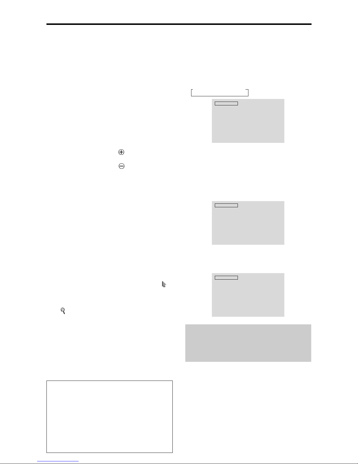
DIGITAL ZOOM
Digital zoom specifies the picture position and enlarges
the picture.
1. (Be sure ZOOM NAV is off.)
Press the POINTER button to display the pointer. ( )
To change the size of the picture:
Press the ZOOM+ button and enlarge the picture.
The pointer will change to resemble a magnifying glass.
(
)
A press of the ZOOM- button will reduce the picture
and return it to its original size.
To change the picture position:
Select the position with the ▲▼
buttons.
2. Press the POINTER button to delete the pointer.
AUTO ADJUST
To adjust the size or quality of the picture
automatically:
Press the AUT O ADJUST button.
Information
AUTO ADJUST ON setting
When RGB (still picture) input is selected:
Fine Picture, Picture ADJ, Position, and Contrast will
be adjusted automatically.
When RGB (motion picture), VIDEO, or Y/Pb/Pr
(component) input is selected: The screen size
switches to ZOOM mode automatically with the
superimposed caption displayed fully only when the
picture contains dark areas above and below the picture.
OFF TIMER
To set the off timer:
The off timer can be set to turn the power off after 30, 60,
90 or 120 minutes.
1. Press the OFF TIMER button to start the timer at 30
minutes.
2. Press the OFF TIMER button to the desired time.
3. The timer starts when the menu turns off.
→ 30 → 60 → 90 → 120 → 0
OFF TIMER 30
To check the remaining time:
1. Once the off timer has been set, press the OFF TIMER
button once.
2. The remaining time is displayed, then turns off after a few
seconds.
3. When five minutes remain the remaining time appears
until it reaches zero.
OFF TIMER 28
To cancel the off timer:
1. Press the OFF TIMER button twice in a row.
2. The off timer is canceled.
OFF TIMER 0
Note:
After the power is turned off with the off timer ...
A slight current is still supplied to the monitor. When you
are leaving the r oom or do not plan to use the system for a
long period of time, turn off the power of the monitor.
Page 15
E-11
WIDE Operations
Wide Screen Operation
(manual)
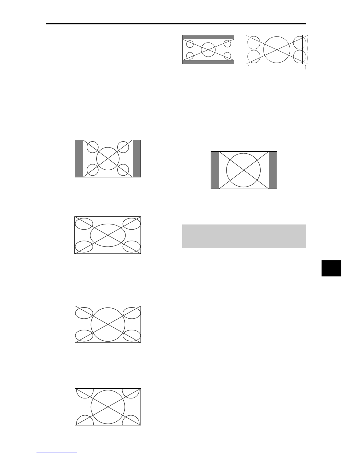
With this function, you can select one of six screen sizes.
When viewing videos or digital video discs
1. Press the WIDE button on the remote control.
2. Within 3 seconds ...
Press the WIDE button again.
The screen size switches as follows:
→ NORMAL → FULL → STADIUM → ZOOM → 2.35:1 → 14:9
When a 720P or 1080I signal is input:
FULL ↔ 2.35:1
When displaying enhanced split screen:
NORMAL ↔ FULL
NORMAL size screen (4:3)
The normal size screen is displayed.
* The picture has the same size as video pictures with a 4 : 3
aspect ratio.
FULL size screen
The image is expanded in the horizontal direction.
* Images compressed in the horizontal direction (“squeezed
images”) are expanded in the horizontal direction and
displayed on the entire screen with correct linearity.
(Normal images are expanded in the horizontal direction.)
STADIUM size screen
The picture is expanded in the horizontal and vertical
directions at different ratios.
* Use this for watching normal video programs (4:3) with a
wide screen.
ZOOM size screen
The picture is expanded in the horizontal and vertical
direction, maintaining the original proportions.
* Use this for theater size (wide) movies, etc.
2.35:1 size screen
The squeezed film image is expanded to fulfill the entire
screen at a ratio of 2.35:1. Black bands do not appear at
the top and bottom but information is lost on the left and
right margins.
• This feature is available when the input signal is video,
component (480I, 480P, 576I, 576P, 720P, 1080I) or RGB
(525P or 625P signal from a scan converter).
*
If black bands appear on the top and bottom in the full size
screen, select the 2.35:1 size screen to avoid phosphor burn-in.
14:9 size screen
The image is displayed at a 14:9 aspect ratio.
* This feature is available when the input signal is video,
component (480I, 480P , 576I, 576P) or RGB (525P or 625P
signal from a scan converter).
Note:
Do not allow the displayed in 4:3 mode for an extended
period. This can cause a phosphor burn-in.
Information is lost on both sides.
Original image
Page 16
E-12
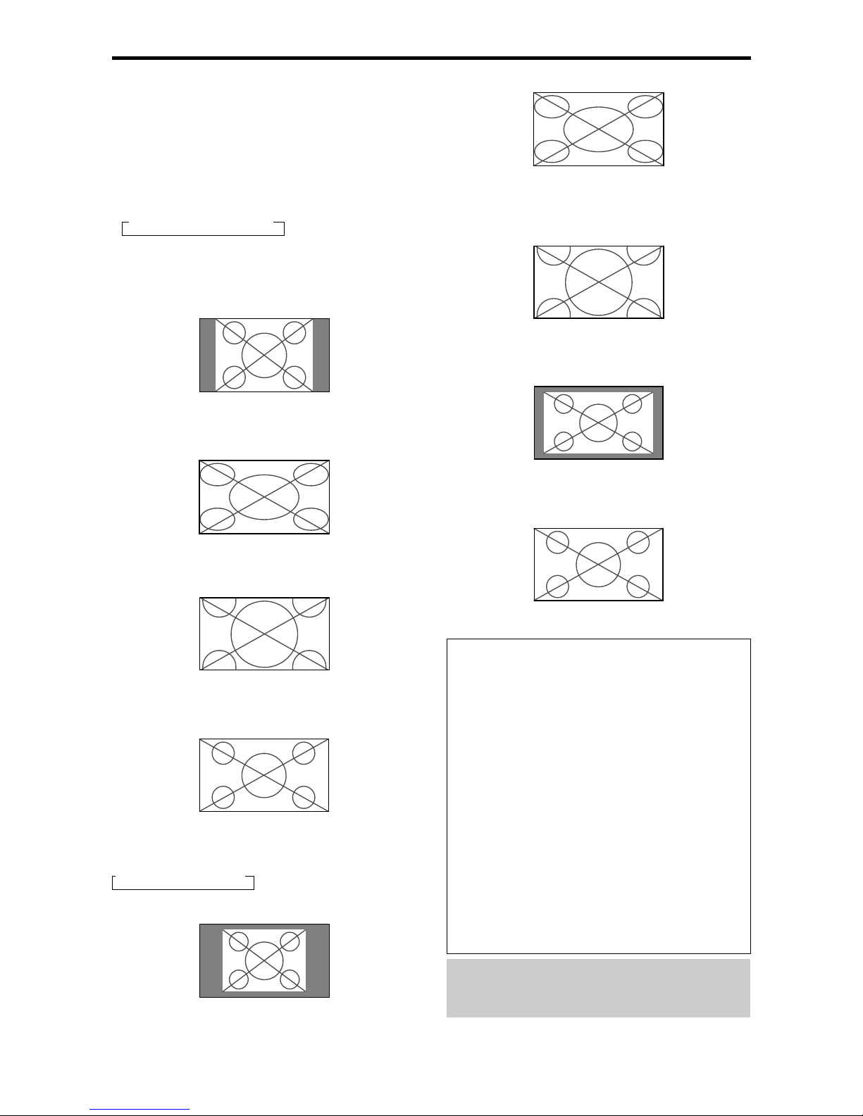
FULL size screen
The image is expanded in the horizontal and vertical
direction.
ZOOM size screen
When wide signals are input.
TRUE
The image is true resolution.
FULL
Information
Supported resolution
See page E-2 of Model Information for details on the
display output of the various VESA signal standards
supported by the monitor.
“PICTURE SIZE” setting
When the setting of “PICTURE SIZE” is OFF , the size
of RGB-input pictures will be TRUE in place of
NORMAL.
When 852 (848) dot 480 line wide VGA*
signals with a vertical frequency of 60 Hz and
horizontal frequency of 31.7 (31.0) kHz are input
Select an appropriate setting for RGB SELECT mode
referring to the“Table of Signals Supported” on page
E-2 of Model Information.
* “VGA”, “SVGA” and “SXGA” are registered
trademarks of IBM, Inc. of the United States.
Note:
Do not allow the displayed in 4:3 mode for an extended
period. This can cause a phosphor burn-in.
Wide Screen Operation with
Computer Signals
Switch to the wide screen mode to expand the 4 : 3 image
to fill the entire screen.
1.Press the WIDE button on the remote control.
2.Within 3 seconds ...
Press the WIDE button again.
The screen size switches as follows:
→ NORMAL → FULL → ZOOM
When displaying enhanced split screen:
NORMAL ↔ FULL
NORMAL size screen (4:3 or SXGA 5:4)
The picture has the same size as the normal computer image.
FULL size screen
The image is expanded in the horizontal direction.
ZOOM size screen
When wide signals are input.
FULL size screen
When “PICTURE SIZE” is set to “OFF”
The screen size switches as follows:
→ TRUE → FULL → ZOOM
TRUE size screen (VGA, SVGA 4:3)
The image is true resolution.
Page 17
E-13
Showing a couple of pictures on the
screen at the same time
* An RGB-input picture may not be displayed in these modes,
depending on the input signal specifications.
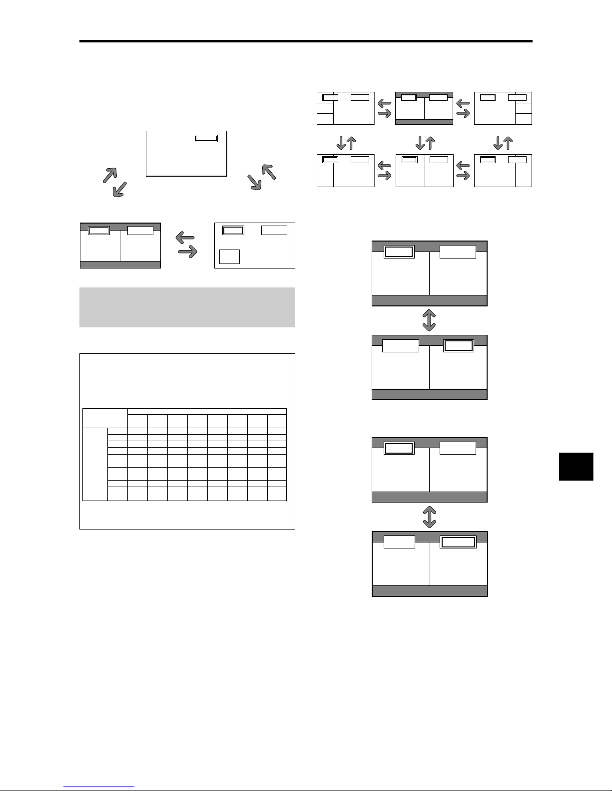
1. Press the button to select a screen mode from among single
mode, side-by-side, and picture-in-picture.
Note:
Picture A and B on the above screen ar e not always of the
same height.
Information
Split screen operations may not function depending on
the combination of input signals. In the table below,
“” means Yes, “” means No.
Split screen operations may not function
depending on the type of the RGB signals.
Operations in the Side-by-side mode
To change the picture size, press the cursor or
button.
To swap the picture on the right and the left, press the
cursor
button.
VIDEO1 RGB/PC1
AB
VIDEO1RGB/PC1
BA
To make the desired picture active, press the SELECT/
FREEZE button.
VIDEO1 RGB/PC1
AB
VIDEO1 RGB/PC1
AB
VIDEO1 RGB/PC2
A
B
VIDEO1 RGB/PC2
AB
VIDEO1 RGB/PC2
B
A
VIDEO1 RGB/PC2
A
B
VIDEO1 RGB/PC2
AB
VIDEO1 RGB/PC2
B
A
Side-by-Side2-R
Side-by-Side1 Side-by-Side2-L
Side-by-Side4-R
Side-by-Side3 Side-by-Side4-L
button
button
button
button
button
button
button
button
button
button
button
button
button
button
button
SPLIT SCREEN Operations
SELECT/FREEZE
button
VIDEO1
Sub
screen
Main screen
RGB/PC1
A
VIDEO1
VIDEO1 RGB/PC1
AB
SIDE BY SIDE
button
PICTURE IN PICTURE
button
SINGLE
button
PICTURE IN
PICTURE
button
SINGLE
button
SIDE BY SIDE
button
VIDEO1
VIDEO2
VIDEO3
HD/DVD1
HD/DVD2
RGB2
RGB/PC1
RGB3
SCART1~3
VIDEO1
VIDEO2
VIDEO3
HD/DVD1
HD/DVD2
RGB2
1,2:
3:
RGB/PC1
1,2:
3:
RGB3
Pictures
displayed on
the left/sub
screen
(Select2)
Pictures displayed on the right/main screen (Select1)
SCART1~3
1,2:
3:
1,2:
3:
Page 18
E-14
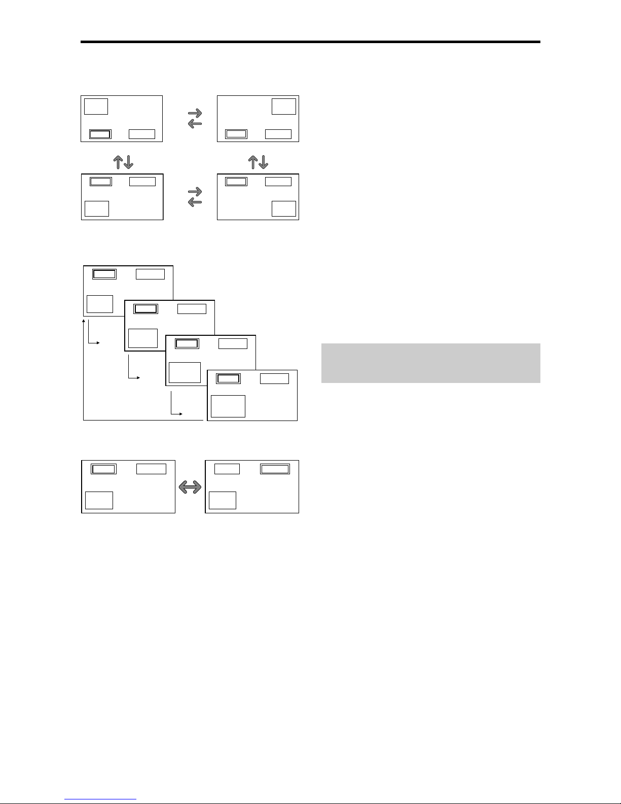
Operations in the Picture-in-picture mode
To move the position of the sub screen, press the cursor
or button.
To change the size of the sub screen, press the
button.
VIDEO1 RGB/PC1
A
B
VIDEO1 RGB/PC1
A
B
VIDEO1 RGB/PC1
A
B
VIDEO1 RGB/PC1
A
B
button
button
button
button
To make the desired picture active, press the SELECT/
FREEZE button.
Selecting the input signals to be displayed
1. Press the SELECT/FREEZE button to make the desired
picture active.
2. Press the RGB/PC, VIDEO, or DVD/HD button.
Each press of the button changes the selection of the input
signal.
The INPUT SELECT button on the monitor can also be
used to change the selection.
Zooming up pictures
1. Press the SELECT/FREEZE button to make the desired
picture active.
2. Use the POINTER button and the ZOOM/ button to
enlage the picture.
For details, see “DIGITAL ZOOM” on page E-10.
Adjusting the OSM controls
1. Press the SELECT/FREEZE button to make the desired
picture active.
2. Press the MENU/ENTER button to display the MAIN
MENU.
3. Adjust the setting to your preference.
For details, see “OSM (On Screen Menu) Controls” on
page E-15.
Note:
During enhanced split screen mode, some functions of
OSM controls ar e not available.
VIDEO1 RGB/PC2
A
B
VIDEO1 RGB/PC2
A
B
VIDEO1 RGB/PC2
A
B
VIDEO1 RGB/PC2
A
B
Bottom Left Bottom Right
button
button
button
button
Top Right
button
button
button
button
Top Left
VIDEO1 RGB/PC1
A
B
VIDEO1 RGB/PC1
A
B
SELECT/
FREEZE
button
Page 19
E-15
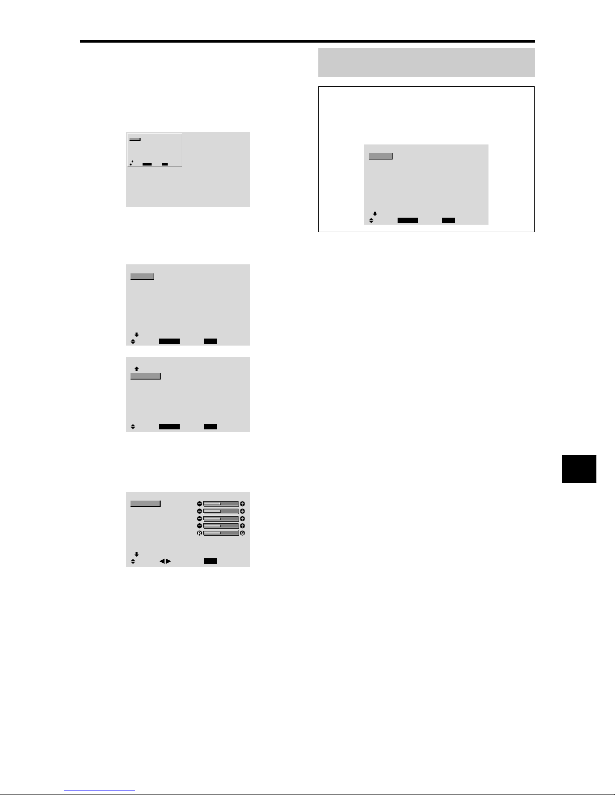
Menu Operations
The OSM window is displayed with respect to the
screen as shown on the diagram.
* Depending on the screen’s mode, the OSM may be
displayed differently .
In the explanation, the OSM section is shown close up.
MAIN MENU
1 / 2
MENU/ENTER
EXIT
PICTURE
AUDIO
IMAGE ADJUST
OPTION1
ADVANCED OSM
NEXT PAGE
: OFF
SEL.
EXIT
OK
The following describes how to use the menus and the
selected items.
1. Press the MENU/ENTER button on the remote control to
display the MAIN MENU.
MAIN MENU
1 / 2
MENU/ENTER
EXIT
PICTURE
AUDIO
IMAGE ADJUST
OPTION1
ADVANCED OSM
NEXT PAGE
: OFF
SEL.
EXIT
OK
MAIN MENU
2 / 2
MENU/ENTER
EXIT
PREVIOUS PAGE
LANGUAGE
COLOR SYSTEM
SOURCE INFORMATION
SEL.
EXIT
OK
2. Press the cursor buttons ▲ ▼ on the remote control to
highlight the menu you wish to enter.
3. Press the MENU/ENTER button on the remote control to
select a sub menu or item.
PICTURE
1 / 2
EXIT
CONTRAST
BRIGHTNESS
SHARPNESS
COLOR
TINT
PICTURE MODE
NR
NEXT PAGE
: NORMAL
: OFF
SEL.
RETURN
ADJ.
4. Adjust the level or change the setting of the selected item
by using the cursor buttons
on the remote control.
5. The adjustments or the settings that are stored in memory.
The change is stored until you change it again.
6. Repeat steps 2 – 5 to adjust an additional item, or press
the EXIT button on the remote control to return to the
main menu.
* When adjusting using the bar at the bottom of the screen,
press the
or button within 5 seconds. If not, the
current setting is set and the previous screen appears.
Note:
The main menu disappears by pressing the EXIT
button.
Information
Advanced menu mode
When “ADVANCED OSM” is set to “ON” in the main
menu (1/2), full menu items will be shown.
MAIN MENU
1 / 2
MENU/ENTER
EXIT
PICTURE
AUDIO
IMAGE ADJUST
OPTION1
OPTION2
OPTION3
OPTION4
ADVANCED OSM
NEXT PAGE
: ON
SEL.
EXIT
OK
OSM(On Screen Menu) Controls
Page 20
E-16
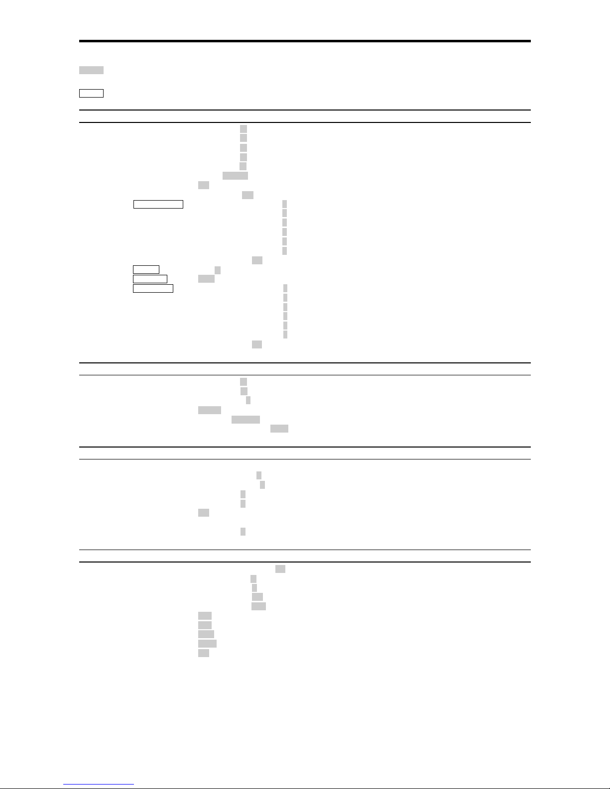
Main menu Sub menu Sub menu 2 Sub menu 3 Sub menu 4 RESET
REFERENCE
PICTURE CONTRAST ←→ 0←52→72 YES E-18
BRIGHTNESS ←→ 0←32→64 YES E-18
SHARPNESS ←→ 0←16→32 YES E-18
COLOR ←→ 0←32→64 YES E-18
TINT R←→G 0←32→64 YES E-18
PICTURE MODE BRIGHT/NORMAL/THEAT.1/THEAT.2/DEFAULT YES E-18
NR OFF/NR-1/NR-2/NR-3 YES E-18
COLOR TEMP LOW/MID LOW/MID/HIGH YES E-18
WHITE BALANCE GAIN RED ←→ 0←→70 YES E-19
GAIN GREEN ←→ 0←→70 YES E-19
GAIN BLUE ←→ 0←→70 YES E-19
BIAS RED ←→ 0←→70 YES E-19
BIAS GREEN ←→ 0←→70 YES E-19
BIAS BLUE ←→ 0←→70 YES E-19
RESET OFF←→ON YES E-19
GAMMA 1←→2←…→4 YES E-19
LOW TONE AUTO←→1←…→3 YES E-19
COLOR TUNE RED Y←→M0←→64 YES E-19
GREEN C←→Y0←→64 YES E-19
BLUE M←→C0←→64 YES E-19
YELLOW G←→R0←→64 YES E-19
MAGENTA R←→B0←→64 YES E-19
CYAN B←→G0←→64 YES E-19
RESET OFF←→ON YES E-19
Main menu Sub menu Sub menu 2 Sub menu 3 Sub menu 4 RESET
REFERENCE
AUDIO BASS ←→ 0←13→26 YES E-20
TREBLE ←→ 0←13→26 YES E-20
BALANCE L←→R -22←0→+22 YES E-20
AUDIO INPUT1 VIDEO 1-3 / HD/DVD 1-2 / RGB 1-3 YES E-20
AUDIO INPUT2 VIDEO 1-3 / HD/DVD 1-2 / RGB 1-3 YES E-20
AUDIO INPUT3 VIDEO 1-3 / HD/DVD 1-2 / RGB 1-3 YES E-20
Main menu Sub menu Sub menu 2 Sub menu 3 Sub menu 4 RESET
REFERENCE
IMAGE ADJUST ASPECT MODE NORMAL/FULL/STADIUM/ZOOM/2.35:1/14:9 — E-20
V-POSITION ←→ -64←0→+64 YES E-20
H-POSITION ←→ -128←0→+127 YES E-20
V-HEIGHT ←→ 0←→64 YES E-20
H-WIDTH ←→ 0←→64 YES E-20
AUTO PICTURE OFF←→ON*
2
NO E-20
FINE PICTURE*
1
←→*20←→64 YES E-20
PICTURE ADJ.*
1
←→*20←→128 YES E-20
Main menu Sub menu Sub menu 2 Sub menu 3 Sub menu 4 RESET
REFERENCE
OPTION1 OSM DISPLAY OSM OFF←→ON YES E-21
OSM ADJ. 1←…→6 YES E-21
OSM ANGLE H←→V YES E-21
OSM ORBITER OFF←→ON YES E-21
OSM CONTRAST LOW←→NORMAL YES E-21
BNC INPUT RGB←→COMP.←→SCART1←→SCART2 YES E-21
D-SUB INPUT RGB←→SCART3 — E-21
RGB SELECT AUTO/STILL/MOTION/WIDE1/WIDE2/WIDE3/DTV YES E-21
HD SELECT 1080B/1035I/1080A NO E-22
INPUT SKIP OFF←→ON YES E-22
ALL RESET OFF←→ON — E-22
:Shaded areas indicate the default value.
←→
: Press the
or button to adjust. The default value is at the center.
:Menu items in a ruled box are available when the ADVANCED OSM is set to ON.
Menu Tree
Page 21
E-17
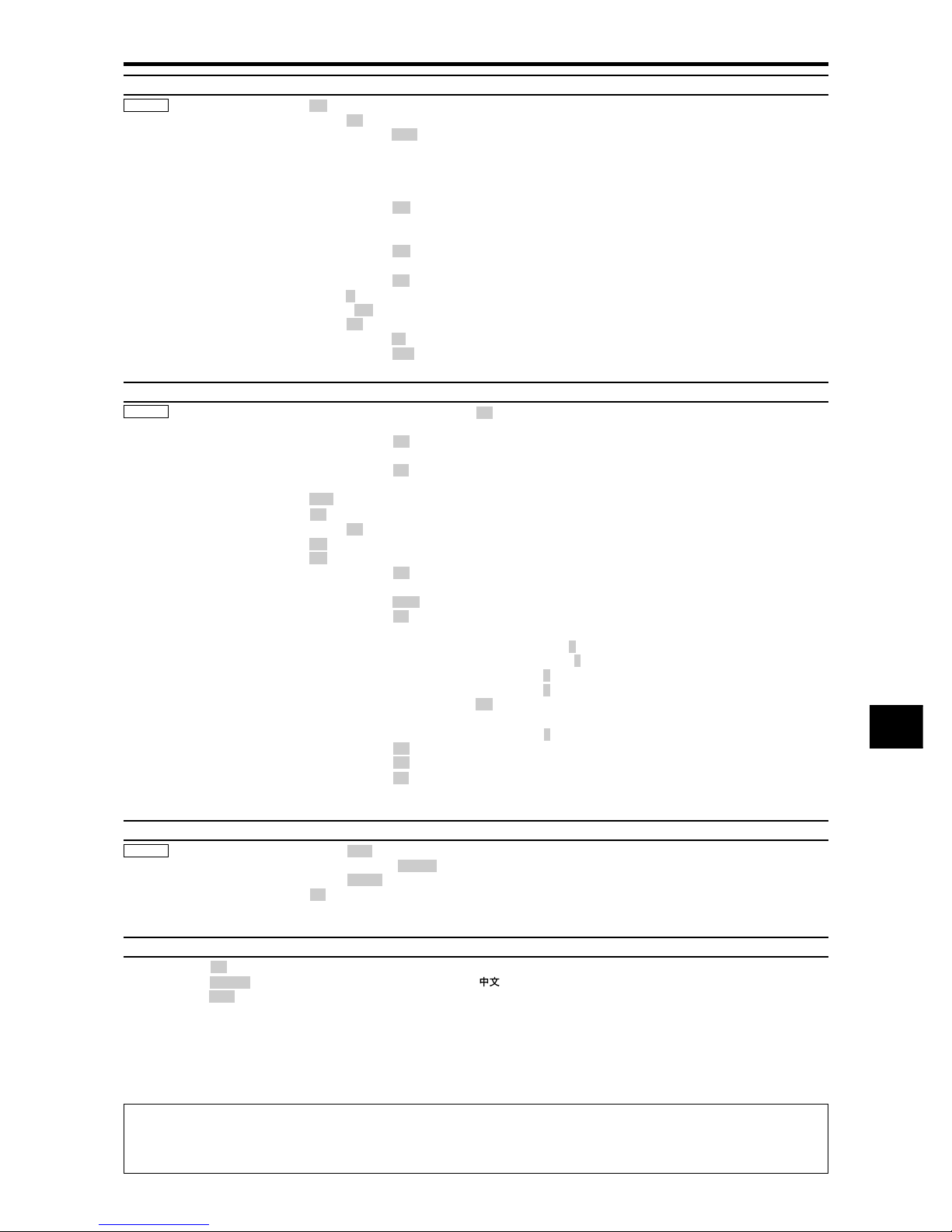
*1 Only when AUTO PICTURE is OFF
*2 RGB/PC only
Main menu Sub menu Sub menu 2 Sub menu 3 Sub menu 4 RESET
REFERENCE
OPTION2 PWR. MGT. OFF←→ON YES E-23
CINEMA MODE OFF←→ON YES E-23
LONG LIFE PLE AUTO/LOCK 1/LOCK 2/LOCK 3 YES E-23
ORBITER AUTO 1 YES E-24
AUTO 2 YES E-24
MANUAL H-DOT/V-LINE/TIME YES E-24
OFF YES E-24
INVERSE OFF YES E-24
ON WORKING TIME/WAITING TIME YES E-24
WHITE YES E-24
SCREEN WIPER OFF YES E-25
ON WORKING TIME/WAITING TIME/SPEED YES E-25
SOFT FOCUS OFF/1/2/3/4 YES E-25
GRAY LEVEL 0←…→3←…→15 YES E-25
S1/S2 AUTO←→OFF YES E-25
PICTURE SIZE OFF←→ON YES E-26
DVI SET UP PLUG/PLAY PC←→STB/DVD NO E-26
BLACK LEVEL LOW←→HIGH NO E-26
Main menu Sub menu Sub menu 2 Sub menu 3 Sub menu 4 RESET
REFERENCE
OPTION3 TIMER PRESENT TIME SUMMER TIME OFF←→ON NO E-26
DAY/HOUR/MINUTES NO E-26
PROGRAM OFF YES E-27
ON DATE/ON/OFF(HOUR, MINUTE)/INPUT/FUNCTION YES E-27
MULTI REPEAT OFF YES E-27
ON MULTI MODE/WORK TIME/INPUT MODE YES E-27
PWR. ON MODE LAST /MULTI/ VIDEO 1-3 / HD/DVD 1-2 / RGB 1-3 YES E-28
CONTROL LOCK OFF←→ON YES E-28
IR REMOTE OFF←→ON YES E-28
LOOP OUT OFF←→ON YES E-28
ID NUMBER ALL←→1←…→256 YES E-29
VIDEO WALL DIVIDER OFF/1/4/9/16/25 YES E-29
POSITION
No.1←…→No.4/No.7←…→No.15/No.16←…→No.31/No.32←…→No.56
— E-29
DISP. MODE SPLIT←→BLANK YES E-30
AUTO ID OFF←→ON YES E-30
IMAGE ADJUST ASPECT MODE NORMAL/FULL/STADIUM/ZOOM/2.35:1/14:9 — E-30
V-POSITION ←→ -64←0→+64 YES E-30
H-POSITION ←→ -128←0→+127 YES E-30
V-HEIGHT ←→ 0←→64 YES E-30
H-WIDTH ←→ 0←→64 YES E-30
AUTO PICTURE OFF←→ON*
2
NO E-30
FINE PICTURE*
1
←→*20←→64 YES E-30
PICTURE ADJ.*
1
←→*20←→128 YES E-30
P. ON DELAY OFF/ON/MODE1/MODE2 YES E-30
PLE LINK OFF←→ON YES E-31
REPEAT TIMER OFF YES E-31
ON DIVIDER/SOURCE/WORK TIME YES E-31
Main menu Sub menu Sub menu 2 Sub menu 3 Sub menu 4 RESET
REFERENCE
OPTION4 SUB P. DETECT OFF←→AUTO YES E-32
ZOOM NAV OFF←→S BY S←→BTM LFT←→BTM RGT←→TOP RGT←→TOP LFT YES E-32
PIC FREEZE OFF←→S BY S1←→S BY S2←→BTM LFT←→BTM RGT←→TOP RGT←→TOP LFT YES E-32
SEAMLESS SW OFF YES E-33
ON SELECT1/SELECT2 YES E-33
Main menu Sub menu Sub menu 2 Sub menu 3 Sub menu 4 RESET
REFERENCE
ADVANCED OSM OFF←→ON YES E-33
LANGUAGE ENGLISH/DEUTSCH/FRANÇAIS/ESPAÑOL/ITALIANO/SVENSKA/
/У NO E-33
COLOR SYSTEM AUTO/3.58NTSC/4.43 NTSC/PAL/PAL 60/PAL-N/PAL-M/SECAM NO E-34
SOURCE INFORMATION
— — E-34
Information
Restoring the factory default settings
Select “ALL RESET” under the OPTION1 menu. Note that this also restores other settings to the factory defaults.
Page 22
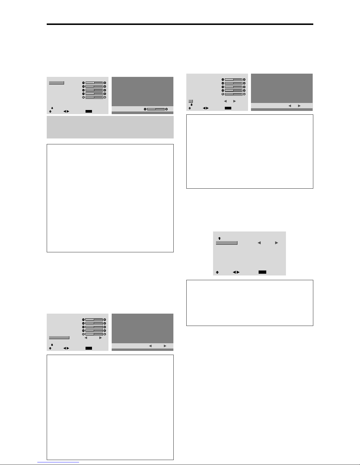
E-18
Picture Settings Menu
Adjusting the picture
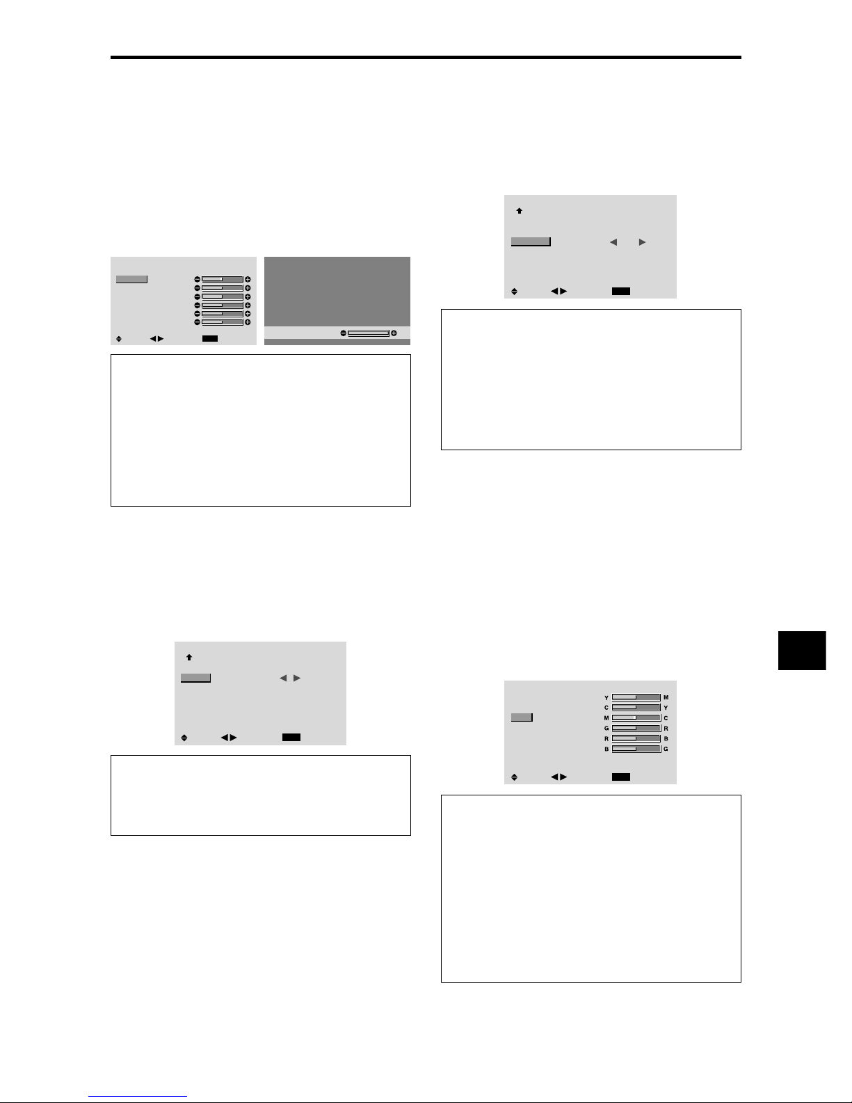
The contrast, brightness, sharpness, color and tint can be
adjusted as desired.
Example: Adjusting the contrast
On “CONTRAST” of “PICTURE” menu, adjust the contrast.
PICTURE
1 / 2
EXIT
CONTRAST
BRIGHTNESS
SHARPNESS
COLOR
TINT
PICTURE MODE
NR
NEXT PAGE
: NORMAL
: OFF
SEL.
RETURN
ADJ.
CONTRAST
52
Note:
If “CAN NOT ADJUST” appears ...
When trying to enter the PICTURE submenu, make sure
PICTURE MODE is not set to DEFAULT.
Information
Picture adjustment screen
CONTRAST: Changes the picture’s white level.
BRIGHTNESS: Changes the picture’s black level.
SHARPNESS: Changes the picture’s sharpness.
Adjusts picture detail of VIDEO display.
COLOR: Changes the color density.
TINT: Changes the picture’s tint. Adjust for natural
colored skin, background, etc.
Adjusting the computer image
Only the contrast and brightness can be adjusted when
a computer signal is connected.
Restoring the factory default settings
Select “DEFAULT” under the “PICTURE MODE”
settings.
Setting the picture mode according to the
brightness of the room
There are four picture modes that can be used effectively
according to the environment in which you are viewing
the display.
Example: Setting the “THEAT. 1” mode
On “PICTURE MODE” of “PICTURE” menu, select
“THEAT. 1”.
PICTURE
1 / 2
EXIT
CONTRAST
BRIGHTNESS
SHARPNESS
COLOR
TINT
PICTURE MODE
NR
NEXT PAGE
: NORMAL
: OFF
SEL.
RETURN
ADJ.
PICTURE MODE
: THEAT. 1
Information
Types of picture modes
THEA T. 1, 2: Set this mode when watching video in a
dark room.
This mode provides darker, finer pictures, like the
screen in movie theaters.
For a darker image, select THEAT. 2.
NORMAL: Set this mode when watching video in a
bright room.
This mode provides dynamic pictures with distinct
differences between light and dark sections.
BRIGHT: This mode provides brighter pictures than
NORMAL.
DEFAULT : Use this to reset the picture to the factory
default settings.
Reducing noise in the picture
Use these settings if the picture has noise due to poor
reception or when playing video tapes on which the picture
quality is poor.
Example: Setting “NR-3”
On “NR” of “PICTURE” menu, select “NR-3”.
PICTURE
1 / 2
EXIT
CONTRAST
BRIGHTNESS
SHARPNESS
COLOR
TINT
PICTURE MODE
NR
NEXT PAGE
: NORMAL
:
OFF
SEL.
RETURN
ADJ.
NR
: NR-3
Information
NR
* “NR” stands for Noise Reduction.
* This function reduces noise in the picture.
Types of noise reduction
There are three types of noise reduction. Each has a
different level of noise reduction.
The effect becomes stronger as the number increases
(in the order NR-1 → NR-2 → NR-3).
OFF: Turns the noise reduction function off.
Setting the color temperature
Use this procedure to set color tone produced by the plasma
display.
Example: Setting “HIGH”
On “COLOR TEMP .” of “PICTURE” menu, select “HIGH”.
PICTURE
2 / 2
EXIT
PREVIOUS PAGE
COLOR TEMP.
GAMMA
LOW TONE
COLOR TUNE
: HIGH
: 2
: AUTO
SEL.
RETURN
ADJ.
Information
Setting the color temperature
LOW: Redder
MID LOW: Slightly red
MID: Standard (slightly bluer)
HIGH: Bluer
Page 23
E-19
Adjusting the color to the desired level
Use this procedure to adjust the white balance for each
color temperature to achieve the desired color quality.
Example: Adjusting the “GAIN RED” of “HIGH” color
temperature
Set “ADVANCED OSM” to “ON” in the main menu (1/
2), then perform the following operations.
On “COLOR TEMP .” of “PICTURE” menu, select “HIGH”,
then press the MENU/ENTER button.
The “WHITE BALANCE” screen appears.
On “GAIN RED”, adjust the white balance.
WHITE BALANCE
COLOR TEMP. HIGH
EXIT
GAIN RED
GAIN GREEN
GAIN BLUE
BIAS RED
BIAS GREEN
BIAS BLUE
RESET : OFF
SEL.
RETURN
ADJ.
GAIN RED
70
Information
Adjusting the white balance
GAIN R/G/B: White balance adjustment for white level
BIAS R/G/B: White balance adjustment for black level
RESET: Resets settings to the factory default values.
Use
and buttons to select “ON”, then press the
MENU/ENTER button.
Restoring the factory default settings
Select “RESET” under the WHITE BALANCE menu.
Changing the Gamma Curve
This feature adjusts the brightness of the midtone areas
while keeping shadows and highlights unchanged.
Example: Setting “3”
Set “ADVANCED OSM” to “ON” in the MAIN MENU
(1/2), then perform the following operations.
On “GAMMA” of “PICTURE” menu, select “3”.
PICTURE
2 / 2
EXIT
PREVIOUS PAGE
COLOR TEMP.
GAMMA
LOW TONE
COLOR TUNE
: MID
: 3
: AUTO
SEL.
RETURN
ADJ.
Information
GAMMA settings
The picture becomes darker as the number increases
(in the sequence of 1, 2, 3, 4).
Making the Low Tone adjustments
This feature allows more detailed tone to be reproduced
especially in the dark area.
Example: Setting “2”
Set “ADVANCED OSM” to “ON” in the MAIN MENU
(1/2), then perform the following operations.
On “LOW TONE” of “PICTURE” menu, select “2”.
PICTURE
2 / 2
EXIT
PREVIOUS PAGE
COLOR TEMP.
GAMMA
LOW TONE
COLOR TUNE
: MID
: 2
: 2
SEL.
RETURN
ADJ.
Information
LOW TONE settings
AUTO: Will automatically appraise the picture and
make adjustments.
1: Will apply the dither method suitable for still pictures.
2: Will apply the dither method suitable for motion
pictures.
3: Will apply the error diffusion method.
Adjusting the colors
Use this procedure to adjust hue and color density for red,
green, blue, yellow, magenta and cyan.
Such adjustments will not affect the other colors.
You can accentuate the green color of trees, the blue of
the sky, etc.
Example: Adjusting the color tune for blue
Set “ADVANCED OSM” to “ON” in the MAIN MENU
(1/2), then perform the following operations.
On “PICTURE” menu, select “COLOR TUNE”, then press
the MENU/ENTER button.
The “COLOR TUNE” screen appears.
On “BLUE” of “COLOR TUNE”, adjust the color tune.
COLOR TUNE
EXIT
RED
GREEN
BLUE
YELLOW
MAGENTA
CYAN
RESET : OFF
SEL.
RETURN
ADJ.
Information
COLOR TUNE settings
RED: Makes red’s adjustment
GREEN: Makes green’s adjustment
BLUE: Makes blue’s adjustment
YELLOW: Makes yellow’s adjustment
MAGENTA: Makes magenta’s adjustment
CYAN: Makes cyan’s adjustment
RESET: Resets settings to the factory default value.
Use
and buttons to select “ON”, then press the
MENU/ENTER button.
Page 24
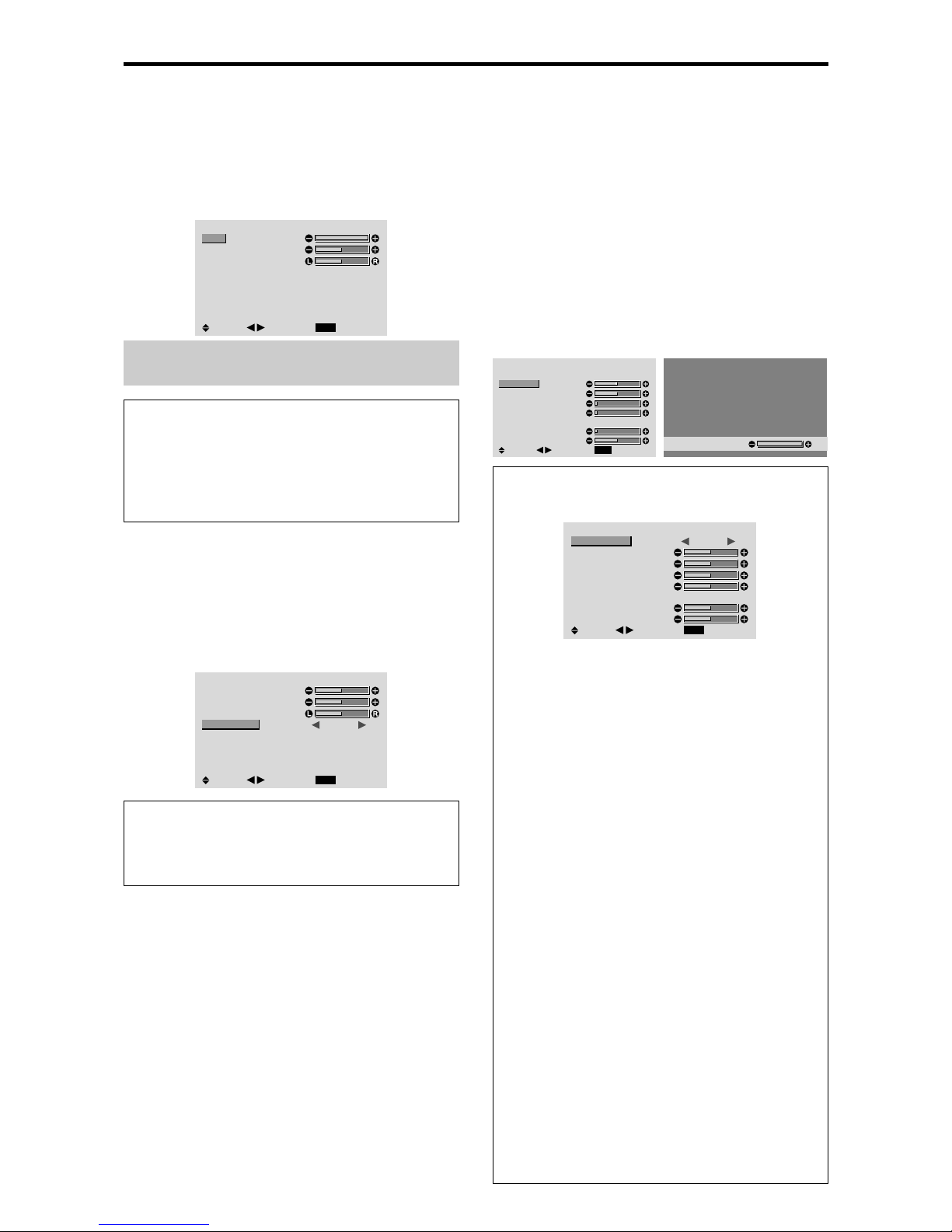
E-20
Audio Settings Menu
Adjusting the treble, bass and left/right
balance and audio input select
The treble, bass and left/right balance can be adjusted to
suit your tastes.
Example: Adjusting the bass
On “BASS” of “AUDIO” menu, adjust the bass.
AUDIO
EXIT
BASS
TREBLE
BALANCE
AUDIO INPUT1
AUDIO INPUT2
AUDIO INPUT3
: VIDEO1
: HD/DVD1
: RGB1
SEL.
RETURN
ADJ.
Note :
If “CAN NOT ADJUST” appears...
Set “AUDIO INPUT” on the AUDIO menu correctly.
Information
䡵 Audio settings menu
BASS: Controls the level of low frequency sound.
TREBLE: Controls the level of high frequency sound.
BALANCE: Controls the balance of the left and right
channels.
Setting the allocation of the audio connectors
Setting the AUDIO 1, 2, and 3 connectors to the desired
input.
Example: Setting “AUDIO INPUT1” to “VIDEO 2”
On “AUDIO INPUT1” of “AUDIO” menu, select
“VIDEO2”.
The available sources depend on the settings of input.
AUDIO
EXIT
BASS
TREBLE
BALANCE
AUDIO INPUT1
AUDIO INPUT2
AUDIO INPUT3
: VIDEO2
: HD/DVD1
: RGB1
SEL.
RETURN
ADJ.
Information
䡵 AUDIO INPUT
A single audio input cannot be selected as the audio
channel for more than one input terminal.
Image Adjust Settings Menu
Adjusting the Position, Size, Fine Picture, Picture Adj
The position of the image can be adjusted and flickering
of the image can be corrected.
Example: Adjusting the vertical position in the normal
mode
On “V -POSITION” of “IMAGE ADJUST” menu, adjust the
position.
The mode switches as follows each time the
䊴
or 䊳 button is
pressed:
NORMAL ↔ FULL
* The mode can also be switched by pressing the WIDE
button on the remote control.
* The settings on the IMAGE ADJUST menu are not preset
at the factory.
IMAGE ADJUST
EXIT
ASPECT MODE
V-POSITION
H-POSITION
V-HEIGHT
H-WIDTH
AUTO PICTURE
FINE PICTURE
PICTURE ADJ.
: NORMAL
: OFF
SEL.
RETURN
ADJ.
V-POSITION
+64
Information
䡵 When “AUTO PICTURE” is “OFF”
IMAGE ADJUST
EXIT
ASPECT MODE
V-POSITION
H-POSITION
V-HEIGHT
H-WIDTH
AUTO PICTURE
FINE PICTURE
PICTURE ADJ.
: FULL
: OFF
SEL.
RETURN
ADJ.
When Auto Picture is off, the Fine Picture and the
Picture ADJ. items are displayed so that you can adjust
them.
䡵 Adjusting the Auto Picture
ON: The Picture ADJ., Fine Picture and Position
adjustments are made automatically.
Not available for digital ZOOM.
OFF: The Picture ADJ., Fine Picture and Position
adjustments are made manually.
* If FINE PICTURE can’t be adjusted, set Auto Picture
to OFF and adjust manually.
䡵 Adjusting the position of the image
V-POSITION: Adjusts the vertical position of the
image.
H-POSITION: Adjusts the horizontal position of the
image.
V-HEIGHT: Adjusts the vertical size of the image.
(Except for STADIUM mode)
H-WIDTH: Adjusts the horizontal size of the image.
(Except for STADIUM mode)
FINE PICTURE*: Adjusts for flickering.
PICTURE ADJ.*: Adjusts for striped patterns on the
image.
* The Picture ADJ. and Fine Picture features are available
only when the “Auto Picture” is off.
* The AUTO PICTURE, FINE PICTURE and PICTURE
ADJ. are available only for RGB signals.
But, these features are not available for moving pictures
on VIDEO, HD/DVD or RGB.
Page 25
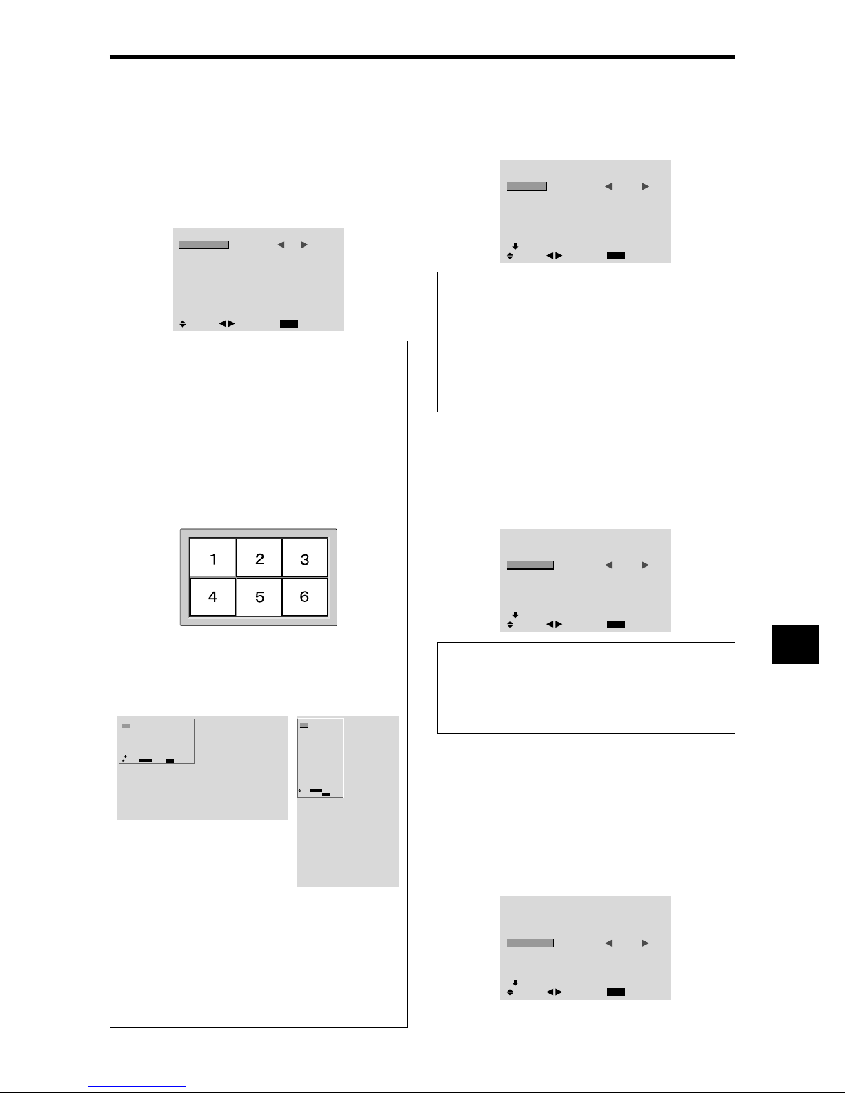
E-21
Option1 Settings Menu
Setting the on-screen menu
This sets the position of the menu, the display format
(horizontal or vertical) etc.
Example: Turning the DISPLAY OSM off
On “OPTION1” menu, select “OSM”, then press the MENU/
ENTER button.
The “OSM” menu appears.
On “DISPLAY OSM” of “OSM” menu, select “OFF”.
OSM
EXIT
DISPLAY OSM
OSM ADJ.
OSM ANGLE
OSM ORBITER
OSM CONTRAST
: OFF
: 1
: H
: OFF
: LOW
SEL.
RETURN
ADJ.
Information
䡵 DISPLAY OSM settings
ON: The on-screen menu appears.
OFF: The on-screen menu does not appear.
If you press the DISPLA Y button on the remote control
for more than 3 seconds the main menu will appear
and can be set (although it is not ON).
䡵 OSM ADJUST settings
Adjusts the position of the menu when it appears on
the screen.
The position can be set between 1 to 6.
䡵 OSM ANGLE settings
Sets the display format (landscape “H” or portrait “V”).
When the unit is installed vertically set the OSM
ANGLE at “V”.
“H”“V”
OPTION1
1 / 4
EXIT
OSM
BNC INPUT
D-SUB INPUT
RGB SELECT
HD SELECT
INPUT SKIP
ALL RESET
NEXT PAGE
: RGB
: RGB
: AUTO
: 1080B
: OFF
: OFF
SEL.
RETURN
MENU/ENTER
OK
䡵 OSM ORBITER settings
ON: The position of the menu will be shifted by eight
dots each time OSM is displayed.
OFF: OSM will be displayed at the same position.
䡵 OSM CONTRAST settings
NORMAL: OSM brightness is set to normal.
LOW: OSM brightness is set to lower.
OPTION1
EXIT
OSM
BNC INPUT
D-SUB INPUT
RGB SELECT
HD SELECT
INPUT SKIP
ALL RESET
: RGB
: RGB
: AUTO
: 1080B
: OFF
: OFF
1024ⴒ768
SEL.
RETURN
MENU/ENTER
OK
Setting the BNC connectors
Select whether to set the input of the 5 BNC connectors to
RGB, component or SCART1,2.
Example: Set the BNC INPUT mode to “COMP.”
On “BNC INPUT” of “OPTION1” menu, select “COMP.”.
OPTION1
1 / 4
EXIT
OSM
BNC INPUT
D-SUB INPUT
RGB SELECT
HD SELECT
INPUT SKIP
ALL RESET
NEXT PAGE
: COMP.
: RGB
: AUTO
: 1080B
: OFF
: OFF
SEL.
RETURN
ADJ.
Information
䡵 BNC INPUT Settings
RGB: Use the 5BNC terminals for RGB input.
COMP.: Use the 3BNC terminals for component input.
SCART1: Use the 4BNC terminals for RGB with
composite sync. See page E-8.
SCART2: Use the 3BNC terminals for RGB and the
VIDEO1 terminal for composite sync. See page E-8.
Setting the RGB1 connector
Select one of the signals being transmitted to the RGB1
terminal.
Example: Set the D-SUB INPUT mode to “SCART3”
On “D-SUB INPUT” of “OPTION1” menu, select
“SCAR T3”.
OPTION1
1 / 4
EXIT
OSM
BNC INPUT
D-SUB INPUT
RGB SELECT
HD SELECT
INPUT SKIP
ALL RESET
NEXT PAGE
: RGB
: SCART3
: AUTO
: 1080B
: OFF
: OFF
SEL.
RETURN
ADJ.
Information
䡵 D-SUB INPUT Settings
RGB: Use the D-SUB terminal for RGB input.
SCART3: Use the D-SUB terminal for RGB signal fed
from SCART. See page E-8.
Setting a computer image to the correct RGB
select screen
With the computer image, select the RGB Select mode
for a moving image such as (video) mode, wide mode or
digital broadcast.
Example: Setting the “RGB SELECT” mode to
“MOTION ”
On “RGB SELECT” of “OPTION1” menu, select
“MOTION”.
OPTION1
1 / 4
EXIT
OSM
BNC INPUT
D-SUB INPUT
RGB SELECT
HD SELECT
INPUT SKIP
ALL RESET
NEXT PAGE
: RGB
: RGB
: MOTION
: 1080B
: OFF
: OFF
SEL.
RETURN
ADJ.
Page 26
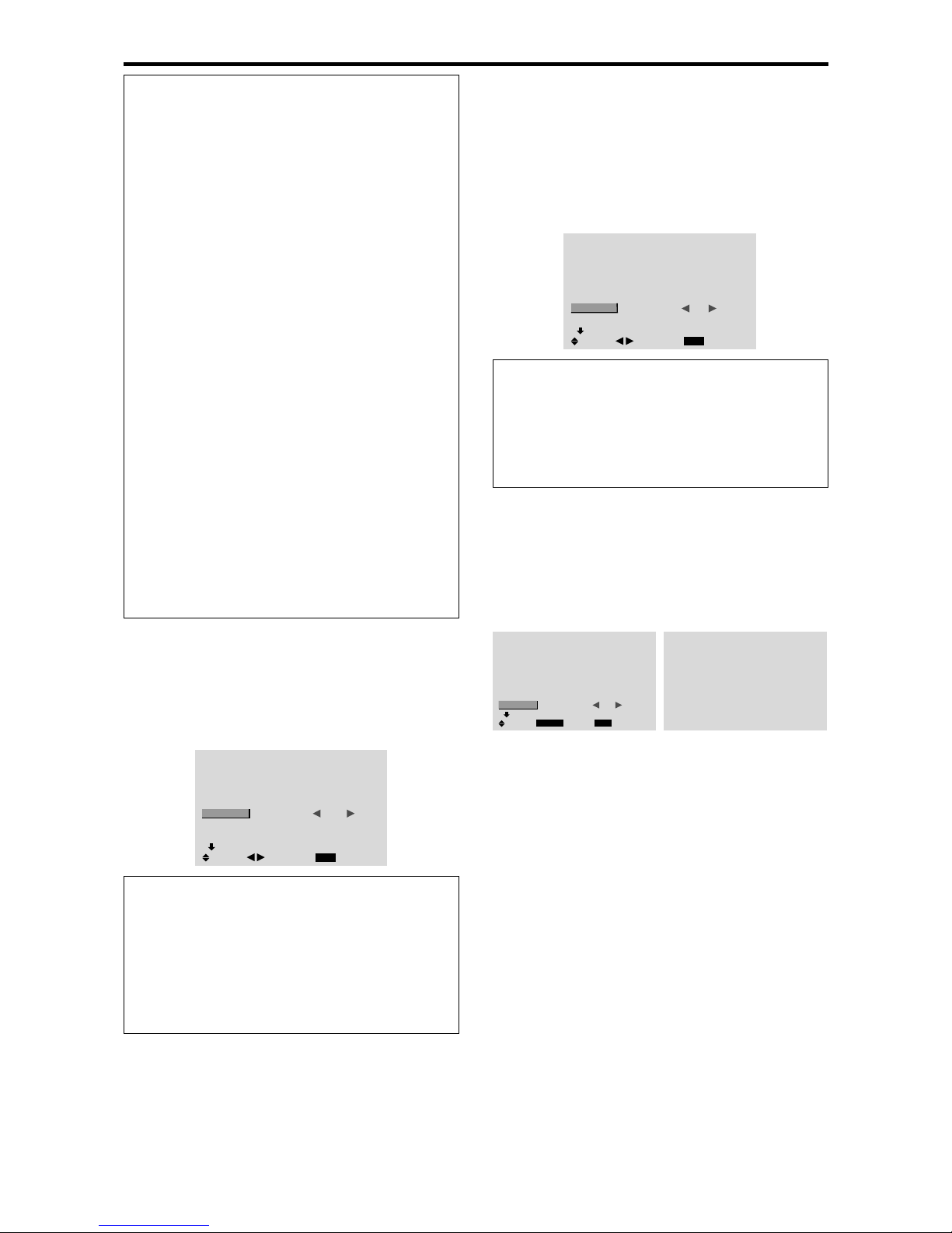
E-22
Information
䡵 RGB SELECT modes
One of these 7 modes must be selected in order to
display the following signals correctly.
AUTO: Select the suitable mode for the specifications
of input signals as listed in the table “Computer input
signals supported by this system” on page E-2 of Model
Information.
STILL: To display VESA standard signals. (Use this
mode for a still image from a computer.)
MOTION: The video signal (from a scan converter)
will be converted to RGB signals to make the picture
more easily viewable. (Use this mode for a motion
image from a computer.)
WIDE1: When an 852 dot⳯ 480 line signal with a
horizontal frequency of 31.7kHz is input, the image may
be compressed horizontally. To prevent this, set RGB
SELECT to WIDE1.
WIDE2: When an 848 dot⳯ 480 line signal with a
horizontal frequency of 31.0 kHz is input, the image
may be compressed horizontally. To prevent this, set
RGB SELECT to WIDE2.
WIDE3: When an 1920 dot⳯ 1200 line signal with a
horizontal frequency of 74.0 kHz is input, the image
may be compressed horizontally. To prevent this, set
RGB SELECT to WIDE3.
DTV: Set this mode when watching digital broadcasting
(480P).
See page E-2 of Model Information for the details of
the above settings.
Setting high definition images to the suitable
screen size
Use this procedure to set whether the number of vertical
lines of the input high definition image is 1035 or 1080.
Example: Setting the “1080B” mode to “1035I”
On “HD SELECT” of “OPTION1” menu, select “1035I”.
OPTION1
1 / 4
EXIT
OSM
BNC INPUT
D-SUB INPUT
RGB SELECT
HD SELECT
INPUT SKIP
ALL RESET
NEXT PAGE
: RGB
: RGB
: AUTO
: 1035
I
: OFF
: OFF
SEL.
RETURN
ADJ.
Information
䡵 HD SELECT modes
These 3 modes are not displayed in correct image
automatically.
1080B: Standard digital broadcasts
1035I: Japanese “High Vision” signal format
1080A: Special Digital broadcasts (for example :
DTC100)
Setting the Input Skip
When this is ON, signals which are not present will be
skipped over and only pictures whose signals are being
transmitted will be displayed.
This setting is valid only for the INPUT SELECT button
on the unit.
Example: Set to “ON”
On “INPUT SKIP” of “OPTION1” menu, select “ON”.
OPTION1
1 / 4
EXIT
OSM
BNC INPUT
D-SUB INPUT
RGB SELECT
HD SELECT
INPUT SKIP
ALL RESET
NEXT PAGE
: RGB
: RGB
: AUTO
: 1080B
: ON
: OFF
SEL.
RETURN
ADJ.
Information
䡵 INPUT SKIP settings
OFF: Regardless of the presence of the signal, scan
and display all signals.
ON: If no input signal is present, skip that signal.
* “SETTING NOW” will appear during the input search.
Resetting to the default values
Use these operations to restore all the settings (PICTURE,
AUDIO, IMAGE ADJUST, OPTION1~4, etc) to the
factory default values.
Refer to page E-16 for items to be reset.
On “ALL RESET” of “OPTION1” menu, select “ON”, then
press the MENU/ENTER button.
OPTION1
1 / 4
EXIT
OSM
BNC INPUT
D-SUB INPUT
RGB SELECT
HD SELECT
INPUT SKIP
ALL RESET
NEXT PAGE
: RGB
: RGB
: AUTO
: 1080B
: OFF
:
ON
SEL.
RETURN
MENU/ENTER
OK
ALL RESET
SETTING NOW
When the “SETTING NOW” screen disappears, then all the
settings are restored to the default values.
Page 27
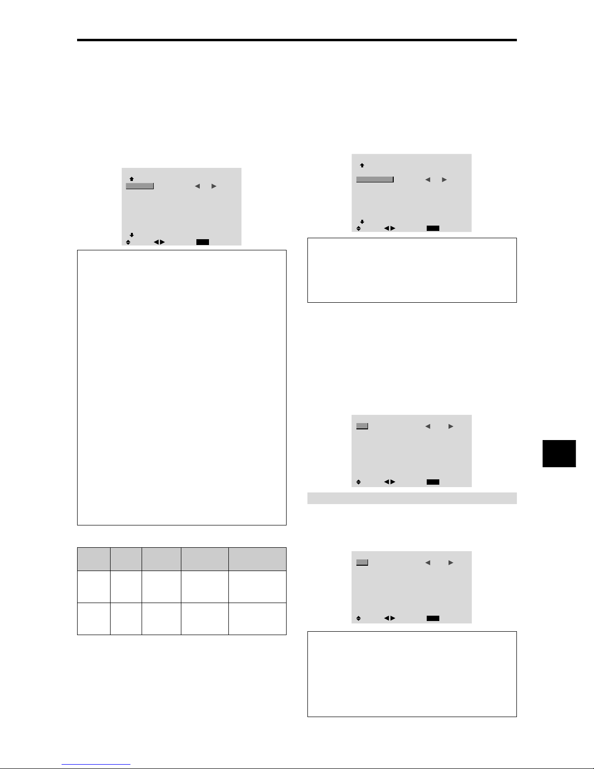
E-23
Option2 Settings Menu
Setting the power management for computer
images
This energy-saving (power management) function
automatically reduces the monitor’s power consumption
if no operation is performed for a certain amount of time.
Example:
Turning the power management function on
Set “ADVANCED OSM” to “ON” in the main menu (1/
2), then perform the following operations.
On “PWR. MGT .” of “OPTION2” menu, select “ON”.
OPTION2
2 / 4
EXIT
PREVIOUS PAGE
PWR. MGT.
CINEMA MODE
LONG LIFE
GRAY LEVEL
S1/S2
PICTURE SIZE
DVI SET UP
NEXT PAGE
: ON
: ON
: 3
: OFF
: ON
SEL.
RETURN
ADJ.
Information
䡵 Power management function
* The power management function automatically reduces
the monitor’s power consumption if the computer’s
keyboard or mouse is not operated for a certain amount
of time. This function can be used when using the
monitor with a computer.
* If the computer’s power is not turned on or if the
computer and selector tuner are not properly connected,
the system is set to the off state.
* For instructions on using the computer’s power
management function, refer to the computer’s operating
instructions.
䡵 Power management settings
ON: In this mode the power management function is
turned on.
OFF: In this mode the power management function is
turned off.
䡵 Power management function and POWER/
STANDBY indicator
The POWER/ST ANDBY indicator indicates the status
of the power management function. See below for
indicator status and description.
POWER/STANDBY indicator
Setting the picture to suit the movie
The film image is automatically discriminated and
projected in an image mode suited to the picture.
[NTSC, PAL, PAL60, 480I (60Hz), 525I (60Hz), 576I
(50Hz), 625I (50Hz), 1035I (60Hz), 1080I (60Hz) only]
Example: Setting the “CINEMA MODE” to “OFF”
Set “ADVANCED OSM” to “ON” in the main menu (1/
2), then perform the following operations.
On “CINEMA MODE” of “OPTION2” menu, select “OFF”.
OPTION2
2 / 4
EXIT
PREVIOUS PAGE
PWR. MGT.
CINEMA MODE
LONG LIFE
GRAY LEVEL
S1/S2
PICTURE SIZE
DVI SET UP
NEXT PAGE
: OFF
: OFF
: 3
: OFF
: ON
SEL.
RETURN
ADJ.
Information
䡵 CINEMA MODE
ON: Automatic discrimination of the image and
projection in cinema mode.
OFF: Cinema mode does not function.
Power
management
mode
On
Off
Turning the picture
back on
Picture already on.
Operate the keyboard or
mouse. The picture
reappears.
POWER/
STANDBY
indicator
Green
Red
Power
management
operating status
Not activated.
Activated.
Description
Horizontal and vertical
synchronizing signals
are present from the
computer.
Horizontal and/or
vertical synchronizing
signals are not sent
from the computer.
Reducing burn-in of the screen
The brightness of the screen, the position of the picture,
positive/negative mode and screen wiper are adjusted to
reduce burn-in of the screen.
Set “ADVANCED OSM” to “ON” in the main menu (1/
2), then perform the following operations.
On “OPTION2” menu, select “LONG LIFE”, then press the
MENU/ENTER button.
The “LONG LIFE” screen appears.
LONG LIFE
EXIT
PLE
ORBITER
INVERSE
SCREEN WIPER
SOFT FOCUS
: AUTO
: OFF
: OFF
: OFF
: OFF
SEL.
RETURN
ADJ.
PLE (Peak Luminance Enhancement)
Use this to activate the brightness limiter.
Example: Setting “PLE” to “LOCK1”
On “PLE” of “LONG LIFE” menu, select “LOCK1”.
LONG LIFE
EXIT
PLE
ORBITER
INVERSE
SCREEN WIPER
SOFT FOCUS
: LOCK1
: OFF
: OFF
: OFF
: OFF
SEL.
RETURN
ADJ.
Information
䡵 PLE settings
AUTO: The brightness of the screen is adjusted
automatically to suit the picture quality.
LOCK1, 2, 3: Sets maximum brightness.
The brightness level decreases in the order of LOCK
1, 2, 3. LOCK 3 provides minimum brightness.
Page 28
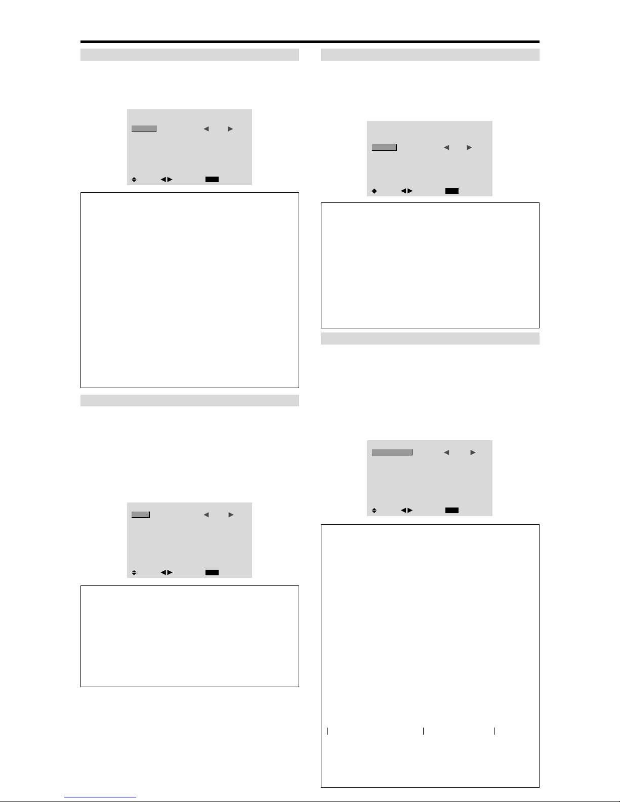
E-24
ORBITER
Use this to set the picture shift.
Example: Setting “ORBITER” to “AUTO1”
On “ORBITER” of “LONG LIFE” menu, select “AUTO1”.
LONG LIFE
EXIT
PLE
ORBITER
INVERSE
SCREEN WIPER
SOFT FOCUS
: AUTO
: AUTO1
: OFF
: OFF
: OFF
SEL.
RETURN
ADJ.
Information
䡵 ORBITER settings
OFF: Orbiter mode does not function.
This is the default setting when RGB is input.
AUTO1: The picture moves around the screen
intermittently, making the picture smaller. This is the
default setting when a V ideo or a DVD/HD/DTV signal
is input. Set to “OFF” when these signals are not used.
AUTO2: The picture moves around the screen
intermittently, making the picture bigger.
MANUAL: User can adjust the orbiter function
(Horizontal Dot, Vertical Line and Time) manually.
See the following explanation.
* When a Video or a DVD/HD/DTV signal is input, the
AUTO1 and 2 functions will affect only the moving
picture and will not make the screen smaller or bigger.
Adjust the ORBITER function manually
Set the amount of shift and the time between movement.
Example: Setting so that the picture moves 2 dots
horizontally and 3 lines vertically every 3 minutes.
On “ORBITER” of “LONG LIFE” menu, select
“MANUAL”, then press the MENU/ENTER button.
THE “ORBITER” screen appears.
Adjust the items.
ORBITER
EXIT
H-DOT
V-LINE
TIME
: 2 DOT
: 4 LINE
: 3 M
SEL.
RETURN
ADJ.
Information
䡵 ORBITER Function settings
H-DOT: Moves from 1 to 20 dots in the horizontal
direction.
V-LINE: Moves from 1 to 20 lines in the vertical
direction.
TIME: Interval of 1~5 minutes (1 horizontal dot or 1
vertical line per interval).
INVERSE
Use this to set the inverse mode or to display a white
screen.
Example: Setting “INVERSE” to “WHITE”
On “INVERSE” of “LONG LIFE” menu, select “WHITE”.
LONG LIFE
EXIT
PLE
ORBITER
INVERSE
SCREEN WIPER
SOFT FOCUS
: AUTO
: OFF
: WHITE
: OFF
: OFF
SEL.
RETURN
ADJ.
Information
䡵 INVERSE Settings
ON: The picture is displayed alternately between
positive image and negative image.
You can set the time by pressing the MENU/ENTER
button while “ON” is set.
OFF: Inverse mode does not function.
WHITE: The entire screen turns white.
You can set the time by pressing the MENU/ENTER
button while “ON” is set.
Setting the time for INVERSE/WHITE
Set a time duration.
Example: Setting to that the INVERSE mode starts
in 2 hours and proceeds for one hour and a half.
On “INVERSE” of “LONG LIFE” menu, select “ON”, then
press the MENU/ENTER button.
THE “INVERSE/WHITE” screen appears.
Adjust the times.
INVERSE/WHITE
EXIT
WORKING TIME
WAITING TIME
: 01H30M
: 02H00M
SEL.
RETURN
ADJ.
Information
䡵 Setting the time
WORKING TIME: Set the time duration for
“INVERSE/WHITE”.
When the WORKING TIME is set to “ON” the mode
will stay on.
WAITING TIME: Set the standby time until the
“INVERSE/WHITE” mode starts.
* The “WAITING TIME” can not be set when the
“WORKING TIME” is ON.
*
THE “WORKING TIME” and “WAITING TIME” can be
set for up to 12 hours and 45 minutes in units of 3 minutes.
* Ending a WORKING TIME function, the monitor will
be ST AND BY.
[Example]
WORKING TIME: 01H30M
WAITING TIME: 02H00M
䡵 To select “ON” for the “WORKING TIME”...
Set the hours of the working time to 0H and the minutes
to 0M. “ON” will be displayed.
←−−−− 2 H −−−−→←−− 1.5 H −−→←−−−−
Start INVERSE/WHITE Start STAND BY
Page 29
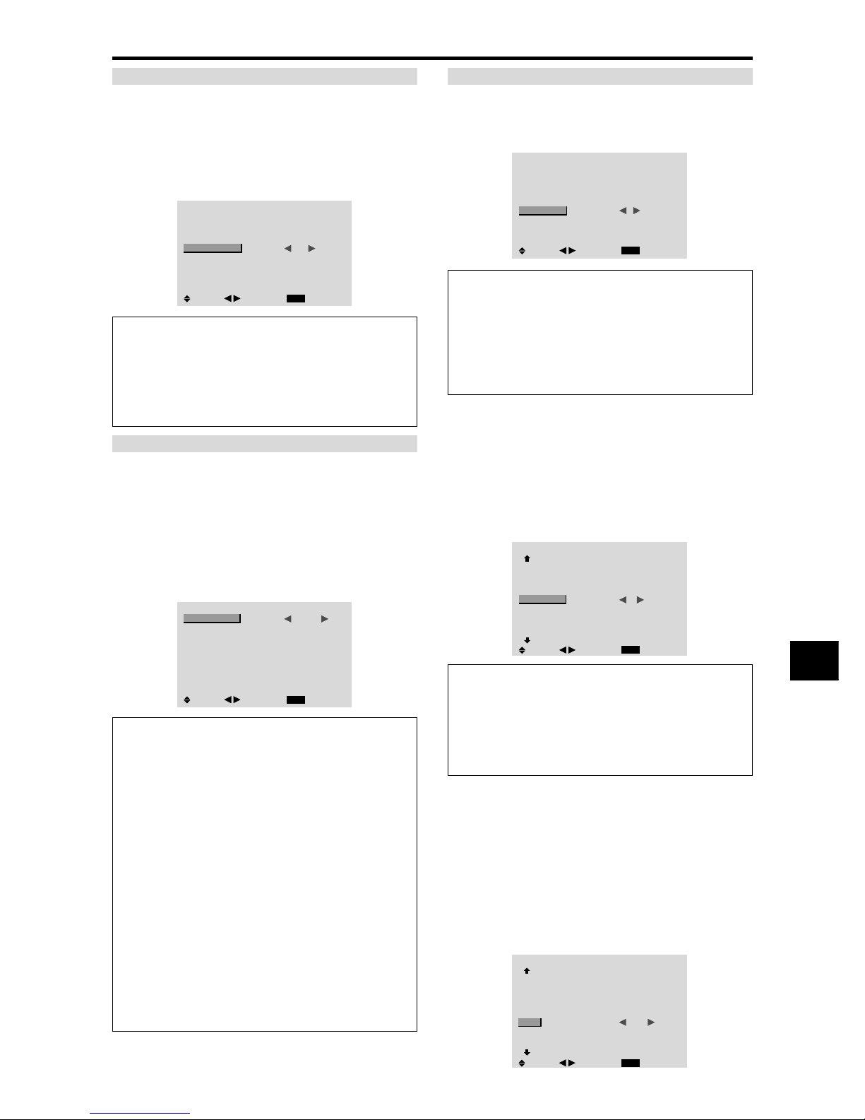
E-25
SCREEN WIPER
When this is set to ON, a white vertical bar moves
repeatedly from the left and of the screen to the right end
at a constant speed.
Example: Setting “SCREEN WIPER” to “ON”
On “SCREEN WIPER” of “LONG LIFE” menu, select
“ON”.
LONG LIFE
EXIT
PLE
ORBITER
INVERSE
SCREEN WIPER
SOFT FOCUS
: AUTO
: OFF
: OFF
: ON
: OFF
SEL.
RETURN
ADJ.
Information
䡵 SCREEN WIPER
ON: The white vertical bar appears.
You can set the time by pressing the MENU/ENTER
button while “ON” is set.
OFF: Screen wiper mode does not function.
Setting the time for SCREEN WIPER
Set a time duration and the speed.
Example: Setting so that the SCREEN WIPER mode
starts in 30 minutes and proceeds for one and a half
hours.
On “SCREEN WIPER” of “LONG LIFE” menu, select
“ON”, then press the MENU/ENTER button.
THE “SCREEN WIPER” screen appears.
Adjust the times and speed.
SCREEN WIPER
EXIT
WORKING TIME
WAITING TIME
SPEED
: 01H30M
: 00H30M
: 3
SEL.
RETURN
ADJ.
Information
䡵 Setting the time
WORKING TIME: Set the time duration for “SCREEN
WIPER”.
When the WORKING TIME is set to “ON” the mode
will stay on.
WAITING TIME: Set the standby time until the
“SCREEN WIPER” mode starts.
SPEED: Set the moving speed for the “SCREEN
WIPER”. The speed decreases as the number increases.
* The “WAITING TIME” can not be set when the
“WORKING TIME” is ON.
* THE “WORKING TIME” and “W AITING TIME” can
be set for up to 12 hours and 45 minutes in units of 3
minutes.
䡵 To select “ON” for the “WORKING TIME”...
Set the hours of the working time to 0H and the minutes
to 0M. “ON” will be displayed.
SOFT FOCUS
Reduces edges and softens the image.
Example: Setting “SOFT FOCUS” to “2”
On “SOFT FOCUS” of “LONG LIFE” menu, select “2”.
LONG LIFE
EXIT
PLE
ORBITER
INVERSE
SCREEN WIPER
SOFT FOCUS
: AUTO
: OFF
: OFF
: OFF
: 2
SEL.
RETURN
ADJ.
Information
䡵 SOFT FOCUS settings
OFF: Turns the SOFT FOCUS function off.
1, 2, 3, 4: Activates the SOFT FOCUS setting. The
higher numbers create a softer image.
“SHARPNESS” can not be adjusted in the “PICTURE”
menu.
Setting the gray level for the sides of the screen
Use this procedure to set the gray level for the parts on the
screen on which nothing is displayed when the screen is
set to the 4:3 size.
Example: Setting “GRAY LEVEL” to “5”
Set “ADVANCED OSM” to “ON” in the main menu (1/
2), then perform the following operations.
On “GRAY LEVEL” of “OPTION2” menu, select “5”.
OPTION2
2 / 4
EXIT
PREVIOUS PAGE
PWR. MGT.
CINEMA MODE
LONG LIFE
GRAY LEVEL
S1/S2
PICTURE SIZE
DVI SET UP
NEXT PAGE
: OFF
: ON
: 5
: OFF
: ON
SEL.
RETURN
ADJ.
Information
䡵 GRAY LEVEL settings
This adjusts the brightness of the black (the gray level)
for the sides of the screen.
The standard is 0 (black). The level can be adjusted
from 0 to 15. The factory setting is 3 (dark gray).
Setting the screen size for S1/S2 video input
If the S-video signal contains screen size information, the
image will be automatically adjusted to fit the screen when
this S1/S2 is set to AUTO.
This feature is available only when an S-video signal is
input via the VIDEO3 terminal.
Example: Setting the “S1/S2” to “AUTO”
Set “ADVANCED OSM” to “ON” in the main menu (1/
2), then perform the following operations.
On “S1/S2” of “OPTION2” menu, select “AUTO”.
OPTION2
2 / 4
EXIT
PREVIOUS PAGE
PWR. MGT.
CINEMA MODE
LONG LIFE
GRAY LEVEL
S1/S2
PICTURE SIZE
DVI SET UP
NEXT PAGE
: OFF
: ON
: 3
: AUTO
: ON
SEL.
RETURN
ADJ.
Page 30
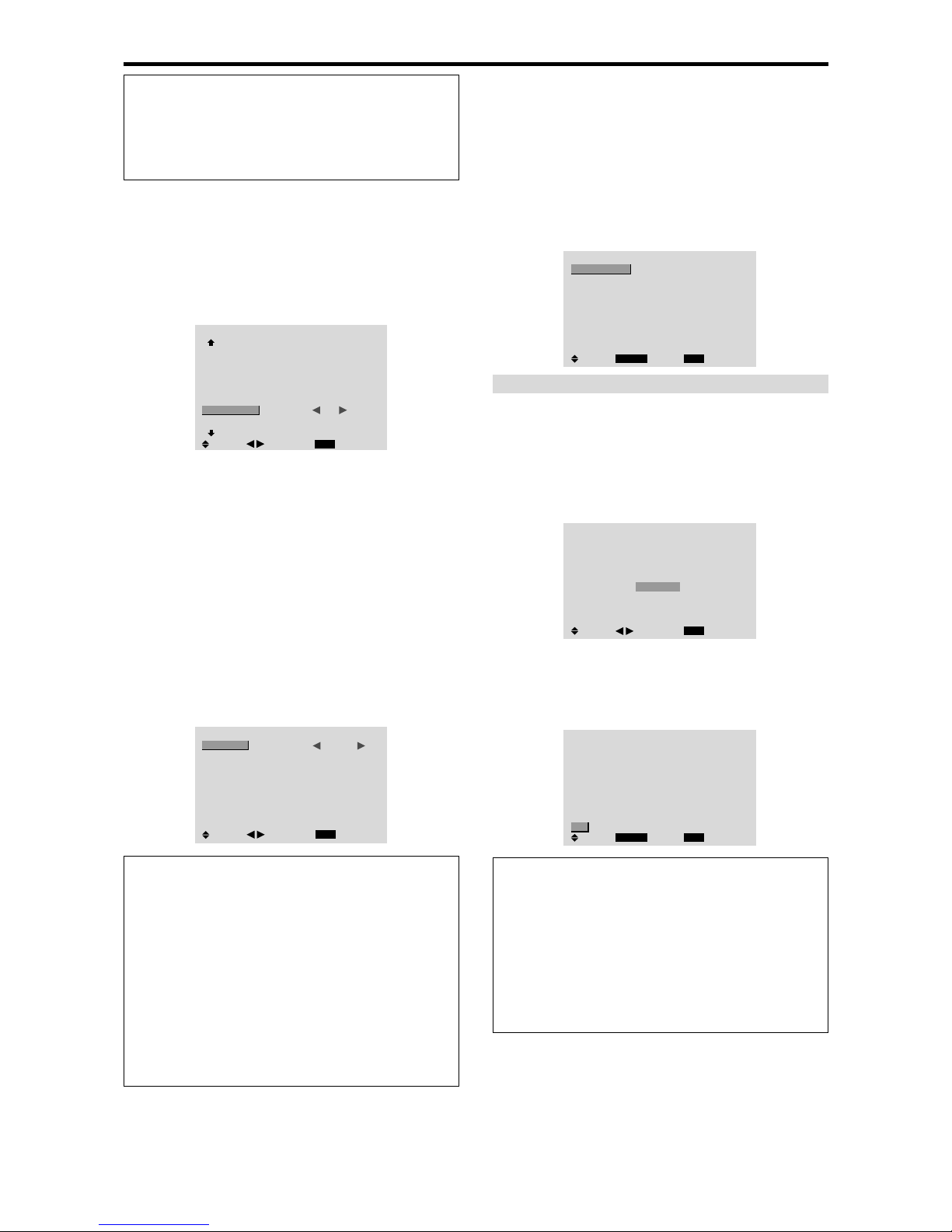
E-26
Setting the picture size for RGB input signals
Use this procedure to switch the setting to “ON” or “OFF”.
Example: Setting the “PICTURE SIZE” mode to
“OFF”
Set “ADVANCED OSM” to “ON” in the main menu (1/
2), then perform the following operations.
On “PICTURE SIZE” of “OPTION2” menu, select “OFF”.
OPTION2
2 / 4
EXIT
PREVIOUS PAGE
PWR. MGT.
CINEMA MODE
LONG LIFE
GRAY LEVEL
S1/S2
PICTURE SIZE
DVI SET UP
NEXT PAGE
: OFF
: ON
: 3
: OFF
:
OFF
SEL.
RETURN
ADJ.
Option3 Settings Menu
Using the timer
This function sets the monitor to turn ON/OFF
automatically at a set time.
Set “ADVANCED OSM” to “ON” in the main menu (1/
2), then perform the following operations.
On “OPTION3” menu, select “TIMER”, then press the
MENU/ENTER button.
The “TIMER” screen appears.
TIMER
EXIT
PRESENT TIME
PROGRAM
MULTI REPEAT
: OFF
: OFF
SEL.
RETURN
MENU/ENTER
OK
PRESENT TIME
This sets the day of the week and present time.
Example: Setting “WEDNESDAY”, “22:05”
On “TIMER” menu, select “PRESENT TIME”, then press
the MENU/ENTER button.
The “PRESENT TIME” screen appears.
Adjust the items.
EXIT
SEL.
RETURN
PRESENT TIME
WEDNESDAY
22 : 05 : 00
RETURN
SUMMER TIME
: OFF
ADJ.
Select “SET”, then press the MENU/ENTER button.
The adjustments are stored and return to the TIMER menu.
* If you press the EXIT button instead of the MENU/ENTER
button, the settings can not be made.
EXIT
SEL.
RETURN
PRESENT TIME
WEDNESDAY
22 : 05 : 00
: OFF
MENU/ENTER
OK
RETURN
SUMMER TIME
SET
Information
䡵 PRESENT TIME settings
SUMMER TIME: Use to set SUMMER TIME.
ON: The present time + 1 hour.
OFF: Cancelled
Day: Set the day of the week (e.g. Sunday).
Hour: Set the hour in the 24-hour format (range 00 to
23).
Minutes: Set the minutes (range 00 to 59).
Setting the signal and black level for DVI
signal
Choose the signal for the DVI connector (PC or STB/
DVD) and set the black level.
Example: Setting the “PLUG/PLAY” mode to “STB/
DVD”
Set “ADVANCED OSM” to “ON” in the main menu (1/
2), then perform the following operations.
On “OPTION2” menu, select “DVI SET UP”, then press the
MENU/ENTER button.
The “DVI SET UP” screen appears.
On “PLUG/PLAY” of “DVI SET UP” menu, select “STB/
DVD”.
DVI SET UP
EXIT
PLUG/PLAY
BLACK LEVEL
: STB/DVD
: HIGH
SEL.
RETURN
ADJ.
Information
䡵 PLUG/PLAY settings
PC: When connected to the PC signal.
BLACK LEVEL is set to “LOW” automatically.
STB/DVD: When connected to the SET TOP BOX,
DVD etc.
BLACK LEVEL is set to “HIGH” automatically.
䡵 BLACK LEVEL settings
LOW: When connected to the PC signal.
HIGH: When connected to the SET TOP BOX, DVD
etc. Change “HIGH” into “LOW” if the black level
appears gray.
Information
䡵 S1/S2 settings
AUTO: Adjusts the screen size automatically according
to the S1/S2 video signal.
OFF: Turns the S1/S2 function off.
Page 31
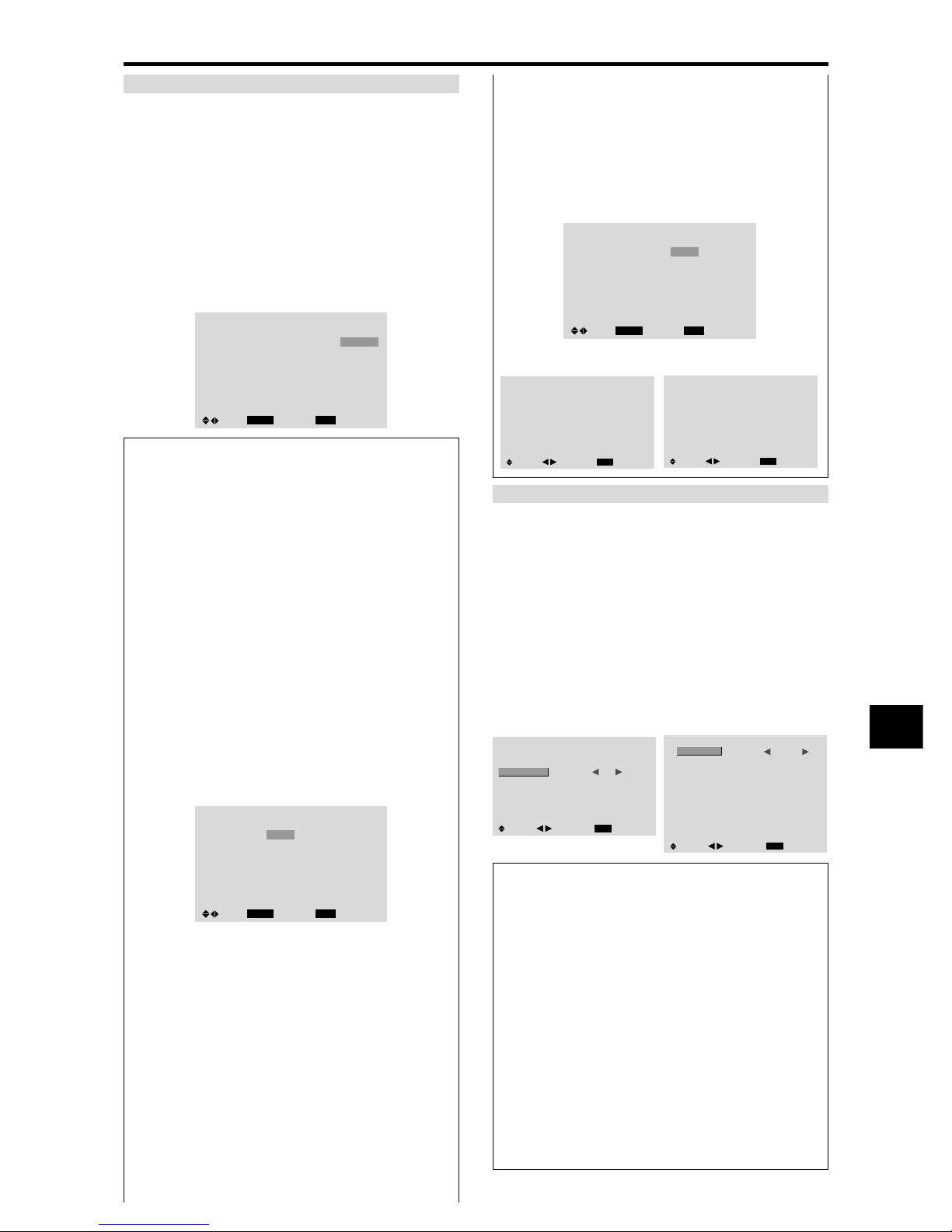
E-27
PROGRAM TIMER
This sets the day and time at which the power will be
switched ON/OFF as well as the input mode.
Example: Setting so that the power will be switched
on at 8:30 A.M., Monday, displaying RGB2 source,
and switched off at 10:30 A.M.
On “PROGRAM” of “TIMER” menu, select “ON”, then
press the MENU/ENTER button.
The “PROGRAM TIMER” screen appears.
Adjust the items.
Each mode switches each time the ZOOM Ⳮ/ⳮ button is
pressed.
PROGRAM TIMER
EXIT
DATE
MON
—
—
—
—
—
—
SEL.
RETURN
ADJ.ZOOM
ON
08 : 30
- - : - -
- - : - -
- - : - -
- - : - -
- - : - -
- - : - -
OFF
10 : 30
- - : - -
- - : - -
- - : - -
- - : - -
- - : - -
- - : - -
INPUT
RGB2
—
—
—
—
—
—
FUNCTION
INVERSE
—
—
—
—
—
—
Information
䡵 PROGRAM TIMER settings
DATE: Set the day of the week (e.g. Sunday).
ON (hour, minutes): Set the time at which the power
will be turned on in the 24-hour format.
OFF (hour, minutes): Set the time at which the power
will be turned off in the 24-hour format.
INPUT: Set the input mode that will be displayed when
the timer is on.
FUNCTION: Set the LONG LIFE function.
䡵 To reset the program
Align the cursor with the DATE field that you wish to
reset, then press the CLEAR/SEAMLESS SW button.
䡵 To reset the data
Align the cursor with the field (ON/OFF/INPUT/
FUNCTION) that you wish to reset, then press the
CLEAR/SEAMLESS SW button.
䡵 Special characters in the PROGRAM TIMER
screen
PROGRAM TIMER
EXIT
DATE
MON
TUE
SAT
*FRI
—
SAT
*
SEL.
RETURN
ADJ.ZOOM
ON
08 : 30
- - : - 08 : 30
08 : 30
- - : - 08 : 30
15 : 30
OFF
10 : 30
18 : 15
12 : 15
10 : 00
- - : - 12 : 15
16 : 00
INPUT
RGB2
—
VIDEO1
HD/DVD1
—
VIDEO1
RGB1
FUNCTION
INVERSE
—
WHITE
—
—
WHITE
—
• An asterisk “*” in the DATE field
An asterisk “*” means “every”. For example, “*FRI”
means every Friday and “*” means everyday.
• A hyphen “-” in the ON field or OFF field
If any hyphen remains in the ON field or OFF field, the
FUNCTION can not be set.
• A hyphen “-” in the FUNCTION field
A hyphen “-” means last mode (the mode that was last
selected at the time the power was switched off).
䡵 To set MULTI INPUT
• Set the INPUT button to “MULTI”, then press the
MENU/ENTER button.
The “MULTI SCREEN SETTING” will appear on
the screen.
• Use the ▲ and ▼ buttons to select “MUL TI MODE”,
then use the
䊴
and 䊳 buttons to choose from
“SINGLE”, “SIDE BY SIDE1~3” and “PICTURE
IN PICTURE (BOTTOM LEFT~TOP LEFT)”.
• Use the ▲ and ▼ buttons to select “MAIN”/ “SUB”
and “LEFT”/“RIGHT”, then use the
䊴
and 䊳 buttons
to choose from “VIDEO1~3”, “HD/DVD1~2” and
“RGB1~3”.
PROGRAM TIMER
EXIT
DATE
MON
TUE
SAT
*FRI
—
SAT
*
SEL.
RETURN
ADJ.ZOOM
ON
08 : 30
- - : - 08 : 30
08 : 30
- - : - 08 : 30
15 : 30
OFF
10 : 30
18 : 15
12 : 15
10 : 00
- - : - 12 : 15
16 : 00
INPUT
MULTI
—
VIDEO1
HD/DVD1
—
VIDEO1
RGB1
FUNCTION
INVERSE
—
WHITE
—
—
WHITE
—
PICTURE IN PICTURE SIDE BY SIDE
PROGRAM TIMER
MULTI SCREEN SETTING
EXIT
MULTI MODE
: BOTTOM LEFT
INPUT MODE
MAIN
SUB
SEL.
RETURN
ADJ.
: RGB/PC1
: VIDEO1
PROGRAM TIMER
MULTI SCREEN SETTING
EXIT
MULTI MODE
: SIDE BY SIDE1
INPUT MODE
LEFT
RIGHT
SEL.
RETURN
ADJ.
: RGB/PC1
: VIDEO1
MULTI REPEAT
Two repeat timers are available.
Each timer has MUL TI MODE, WORK TIME and INPUT
MODE functions.
Example:
TIMER1 is set to display RGB1 (MAIN) and VIDEO1
(SUB) for 4 hours in picute-in-picture mode.
TIMER2 is set to display RGB3 (LEFT) and HD/DVD1
(RIGHT) for 2.5 hours in side-by-side mode.
On “MULTI REPEAT” of “TIMER”, select “ON”, then
press the MENU/ENTER button.
The “MULTI REPEAT TIMER” screen appears.
Adjust the items.
TIMER
EXIT
PRESENT TIME
PROGRAM
MULTI REPEAT
: OFF
: OFF
SEL.
RETURN
ADJ.
MULTI REPEAT TIMER
EXIT
1 MULTI MODE
WORK TIME
INPUT MODE
MAIN
SUB
2 MULTI MODE
WORK TIME
INPUT MODE
LEFT
RIGHT
: BTM LFT
: 04H00M
: RGB/PC1
: VIDEO1
: S BY S1
: 02H30M
: RGB/PC3
: HD/DVD1
SEL.
RETURN
ADJ.
Information
䡵 MULTI REPEAT settings
MULTI MODE: Set the input mode to be displayed
while the timer is on.
WORK TIME: Set the time duration of the display.
Time range is from 1 minutes to 4 hours and 15 minutes.
INPUT MODE: Set the signal that will be displayed
within the selected screen.
Select “MAIN” or “SUB” for “PICTURE IN PICTURE
(BTM LFT~TOP LFT)” and “LEFT” or “RIGHT” for
“S BY S1~3”. Only one signal is selected for
“SINGLE”.
* The two repeat timers run consecutively, i.e., Timer1–
Timer2–Timer1–Timer2.
* When both PROGRAM TIMER and MUL TI REPEA T
TIMER are set, priority is given to PROGRAM TIMER.
Page 32
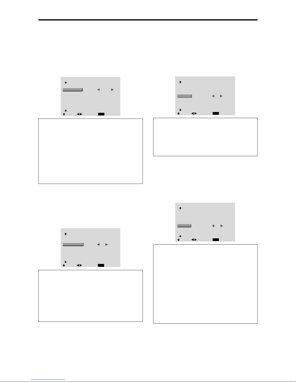
E-28
Setting the power on mode
This function sets the input mode at the time the power is
switched on.
Example: Setting “VIDEO2”
Set “ADVANCED OSM” to “ON” in the main menu (1/
2), then perform the following operations.
On “PWR. ON MODE” of “OPTION3” menu, select
“VIDEO2”.
The available sources depend on the settings of input.
OPTION3
3 / 4
EXIT
PREVIOUS PAGE
TIMER
PWR. ON MODE
CONTROL LOCK
IR REMOTE
LOOP OUT
ID NUMBER
VIDEO WALL
NEXT PAGE
: VIDEO2
: OFF
: ON
: OFF
: ALL
SEL.
RETURN
ADJ.
Information
䡵 PWR. ON MODE settings
LAST: Last mode (the input that was last selected at
the time the power was switched off).
VIDEO1, 2, 3: VIDEO input mode.
RGB1, 2, 3: RGB input mode.
HD/DVD1, 2: HD/DVD input mode.
DVD2, 3: DVD input mode.
MULTI: Multi screen mode.
Follow the procedure used for PROGRAM TIMER. See
page E-27.
Enabling/disabling the front panel controls
This function enables/disables the front panel controls.
Example: Setting “ON”
Set “ADVANCED OSM” to “ON” in the main menu (1/
2), then perform the following operations.
On “CONTROL LOCK” of “OPTION3” menu, select
“ON”, then press the MENU/ENTER button.
OPTION3
3 / 4
EXIT
PREVIOUS PAGE
TIMER
PWR. ON MODE
CONTROL LOCK
IR REMOTE
LOOP OUT
ID NUMBER
VIDEO WALL
NEXT PAGE
: LAST
: ON
: ON
: OFF
: ALL
SEL.
RETURN
ADJ.
Information
䡵 CONTROL LOCK settings
ON: Disables the buttons on the front panel.
OFF: Enables the buttons on the front panel.
* Even when the CONTROL LOCK is set, the POWER
switch will not be locked.
* This becomes effective when the on-screen menu goes
out.
Enabling/disabling remote control wireless
transmission
This function enables/disables remote control wireless
transmission.
Example: Setting “OFF”
Set “ADVANCED OSM” to “ON” in the main menu (1/
2), then perform the following operations.
On “IR REMOTE” of “OPTION3” menu, select “OFF”, then
press the MENU/ENTER button.
OPTION3
3 / 4
EXIT
PREVIOUS PAGE
TIMER
PWR. ON MODE
CONTROL LOCK
IR REMOTE
LOOP OUT
ID NUMBER
VIDEO WALL
NEXT PAGE
: LAST
: OFF
: OFF
: OFF
: ALL
SEL.
RETURN
ADJ.
Information
䡵 IR REMOTE settings
ON: Enables remote control wireless transmission.
OFF: Disables remote control wireless transmission.
Set “OFF” to avoid unwanted control from other remote
controls.
Loop Out setting
When this feature is set to ON, the received signal will be
looped out.
Example: Setting “ON”
Set “ADVANCED OSM” to “ON” in the main menu (1/
2), then perform the following operations.
On “LOOP OUT” of “OPTION3” menu, select “ON”.
OPTION3
3 / 4
EXIT
PREVIOUS PAGE
TIMER
PWR. ON MODE
CONTROL LOCK
IR REMOTE
LOOP OUT
ID NUMBER
VIDEO WALL
NEXT PAGE
: LAST
: OFF
: ON
: ON
: ALL
SEL.
RETURN
ADJ.
Information
䡵 LOOP OUT settings
ON: The received signal will be looped out via PC1
terminal or VIDEO1 terminal.
OFF: The received signal will not loop out.
* Even if LOOP OUT is ON, signals won’t be sent out if
POWER is being turned off.
䡵 To connect another display...
See page E-5.
䡵 If the RGB/PC1 signal is present at the time
the power switched on...
The RGB/PC1 input will be displayed regardless of the
setting of LOOP OUT.
Page 33
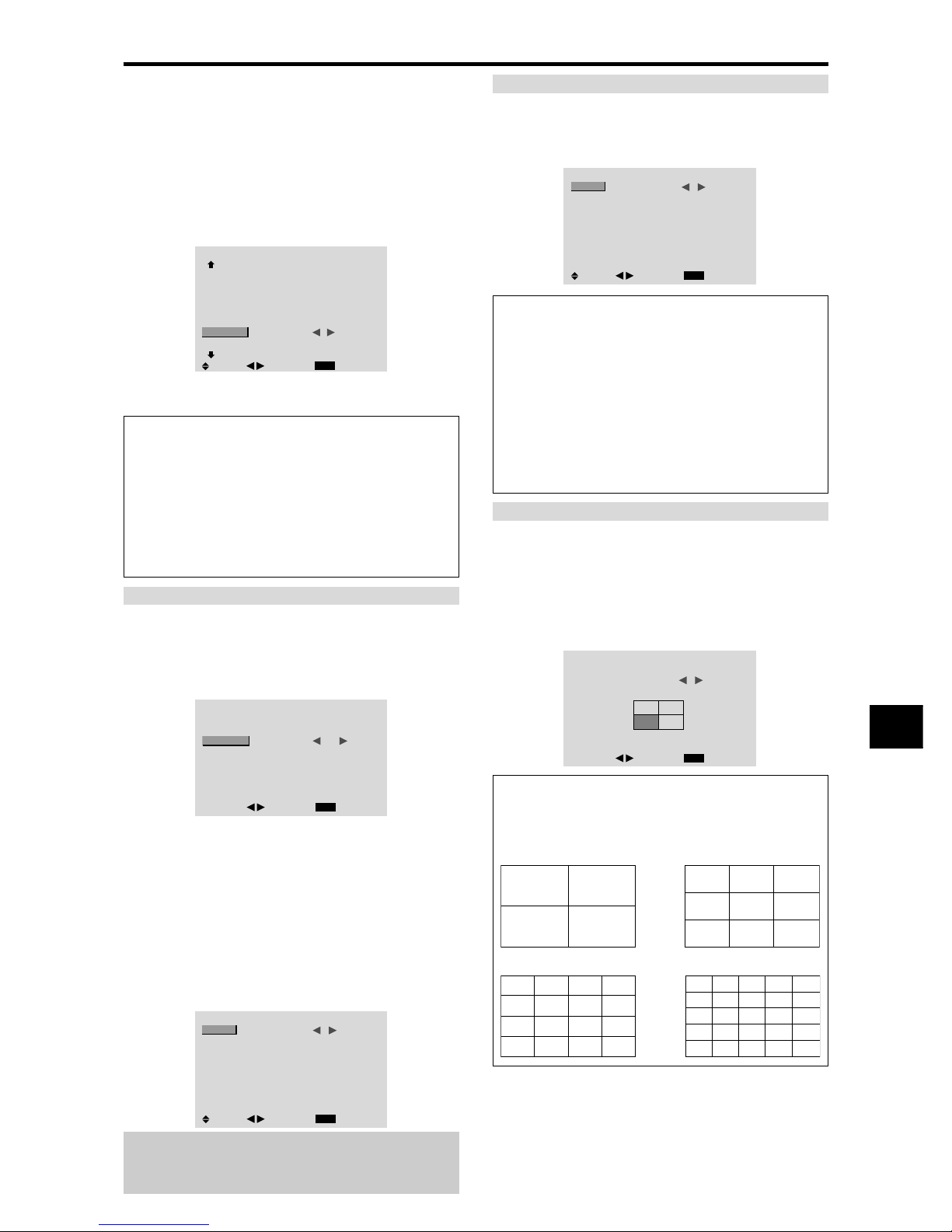
E-29
ID number setting
When using more than one of these displays, this function
sets ID numbers so that operation of the remote control
does not cause multiple monitors to operate at the same
time.
Example: Setting “2”
Set “ADVANCED OSM” to “ON” in the main menu (1/
2), then perform the following operations.
On “ID NUMBER” of “OPTION3” menu, select “2”.
OPTION3
3 / 4
EXIT
PREVIOUS PAGE
TIMER
PWR. ON MODE
CONTROL LOCK
IR REMOTE
LOOP OUT
ID NUMBER
VIDEO WALL
NEXT PAGE
: LAST
: OFF
: ON
: OFF
: 2
SEL.
RETURN
ADJ.
* T o reset back to ALL
Press the CLEAR/SEAMLESS SW button
Information
䡵 ID NUMBER settings
ALL: ID NUMBER will not be set.
1 to 256: ID NUMBER will be set.
䡵 When the ID NUMBER have been set
You can also set ID NUMBER for each remote control
to operate the plasma display individually. To do so,
see the following explanation.
To set the ID number for the remote control
Example: Setting “2”
Press the ID SELECT button on the remote control.
The “ID SELECT” screen appears.
On “ID NUMBER” of “ID SELECT” menu, select “2”.
ID SELECT
POSITION : 1
EXIT
: 2
RETURN
ADJ.
ID NUMBER
* T o reset back to ALL
Press the CLEAR/SEAMLESS SW button
Video Wall setting
Use this feature to configure a 4-25 video wall.
Set “ADVANCED OSM” to “ON” in the main menu (1/
2), then perform the following operations.
On “OPTION3” menu, select “VIDEO WALL”, then press
the MENU/ENTER button.
The “VIDEO WALL” screen appears.
VIDEO WALL
EXIT
DIVIDER
POSITION
DISP. MODE
AUTO ID
IMAGE ADJUST
P. ON DELAY
PLE LINK
REPEAT TIMER
: 1
: SPLIT
: OFF
: OFF
: OFF
: OFF
SEL.
RETURN
ADJ.
Note:
A contingency method of shutting off the electric
power should be used in cases of emergency during video
wall setup.
DIVIDER
Set the 4-25 video wall.
Example: Setting “4”
On “DIVIDER” of “VIDEO WALL” menu, select “4”.
VIDEO WALL
EXIT
DIVIDER
POSITION
DISP. MODE
AUTO ID
IMAGE ADJUST
P. ON DELAY
PLE LINK
REPEAT TIMER
: 4
: SPLIT
: OFF
: OFF
: OFF
: OFF
SEL.
RETURN
ADJ.
Information
䡵 DIVIDER settings
OFF, 1: 1 Screen (Matrix display function does not
work)
4: 4 Screens (2×2 video wall)
9: 9 Screens (3×3 video wall)
16: 16 Screens (4×4 video wall)
25: 25 Screens (5×5 video wall)
* When you select 4-25, set the VIDEO WALL
POSITION.
VIDEO WALL POSITION
Set the position of each display.
Example: Setting “4”
On “VIDEO WALL” menu, select “POSITION”, then press
the MENU/ENTER button.
The “VIDEO WALL POSITION” screen appears.
Select “NO. 4” of “POSITION NO.”.
VIDEO WALL POSITION
POSITION NO.
4
EXIT
RETURN
ADJ.
Information
䡵 VIDEO WALL POSITION settings
1 Screen: There is no need to set POSITION.
4 Screens 9 Screens
16 Screens 25 Screens
NO. 1
NO. 2
NO. 4
NO. 3
NO. 7
NO. 8
NO. 9
NO. 10
NO. 11
NO. 12
NO. 13
NO. 14
NO. 15
NO. 16 NO. 17 NO. 18 NO. 19
NO. 20 NO. 21 NO. 22 NO. 23
NO. 24 NO. 25 NO. 26 NO. 27
NO. 28 NO. 29 NO. 30 NO. 31
NO. 32 NO. 33 NO. 34 NO. 35 NO. 36
NO. 37 NO. 38 NO. 39 NO. 40 NO. 41
NO. 42 NO. 43 NO. 44 NO. 45 NO.46
NO. 47 NO. 48 NO. 49 NO. 50 NO. 51
NO. 52 NO. 53 NO. 54 NO. 55 NO. 56
Page 34
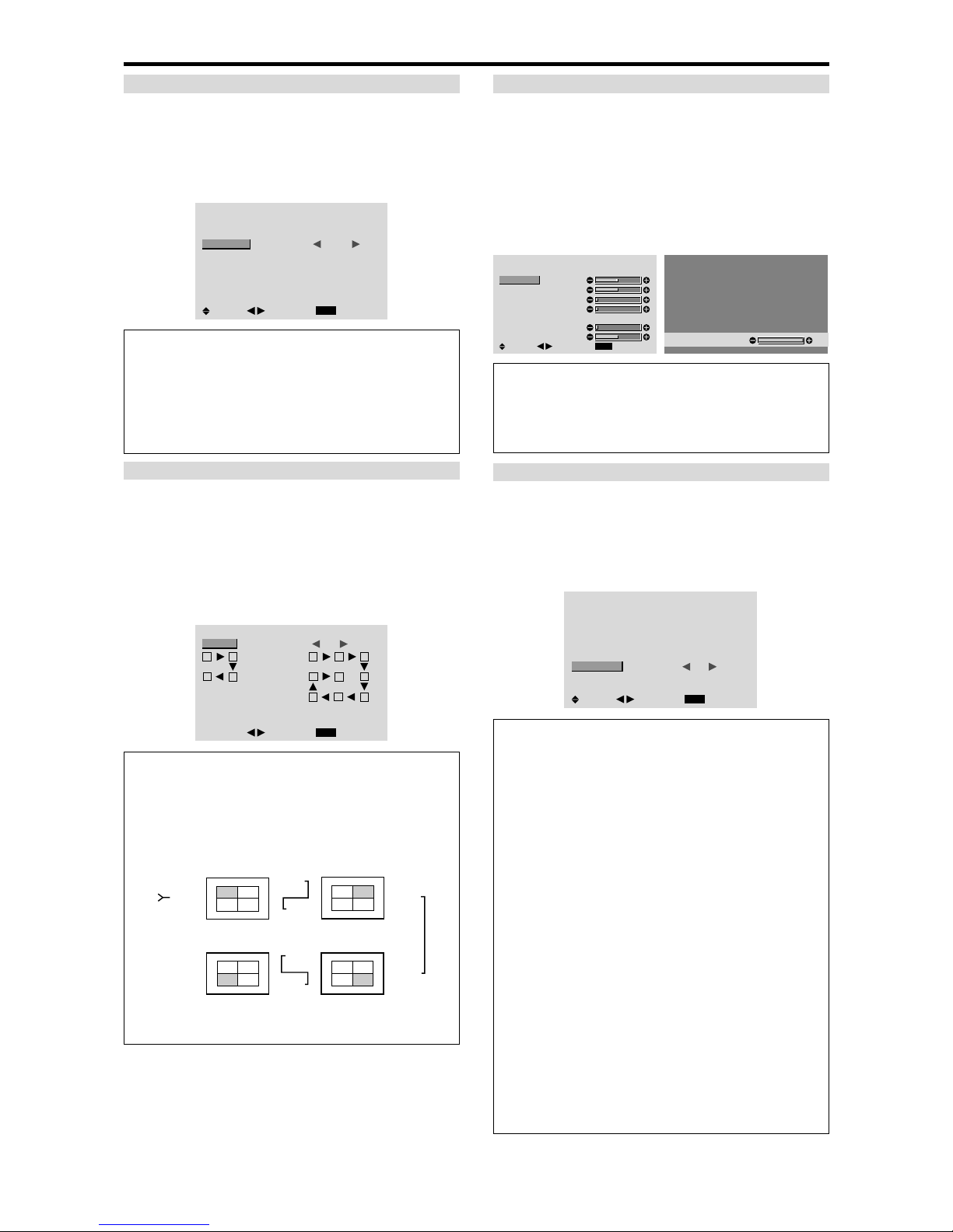
E-30
DISP. MODE
Select the screen mode from between two options
(Splitting, Blanking).
Example: Setting “BLANK”
On “DISP. MODE” of “VIDEO WALL” menu, select
“BLANK”.
VIDEO WALL
EXIT
DIVIDER
POSITION
DISP. MODE
AUTO ID
IMAGE ADJUST
P. ON DELAY
PLE LINK
REPEAT TIMER
: 1
: BLANK
: OFF
: OFF
: OFF
: OFF
SEL.
RETURN
ADJ.
Information
䡵 DISP. MODE settings
SPLIT: Combines enlarged screens and creates multiple
screens.
BLANK: Corrects misalignment of combined screen
portions and creates multiple screens
AUTO ID
This feature automatically sets the ID numbers of multiple
displays connected to each other.
Example: Setting “ON”
Set the ID number for the No. 1 display on ID NUMBER
menu.
On “AUTO ID” of “VIDEO WALL” menu, select “ON”,
then press the MENU/ENTER button.
AUTO ID
EXIT
AUTO ID : ON
RETURN
ADJ.
1
2
4
3
1
2
8
9
3
4
6
5
7
WIRED CABLE
CONNECTION TURN
Information
䡵 AUTO ID settings
ON: Enables Auto ID function. In the case shown below ,
display 1 will be set as ID 1, display 2 as ID2, etc.
This can be set only when a 2×2 or 3×3 video wall is
selected.
REMOTE
IN
REMOTE
IN
REMOTE
OUT
REMOTE
OUT
REMOTE
IN
REMOTE
OUT
REMOTE
OUT
REMOTE
IN
No.1
No.2
No.3No.4
No.1
No.2
No.3No.4
No.1
No.2
No.3No.4
No.1
No.2
No.3No.4
Display 1
Display 2
Display 4
Display 3
OFF: Disables Auto ID function.
IMAGE ADJUST
The position of the image can be adjusted and flickering
of the image can be corrected.
Example: Adjusting the vertical position
On “VIDEO W ALL” menu, select “IMAGE ADJUST”, then
press the MENU/ENTER button.
The “IMAGE ADJUST” screen appears.
On “V -POSITION” of “IMAGE ADJUST” menu, adjust the
position.
IMAGE ADJUST
EXIT
ASPECT MODE
V-POSITION
H-POSITION
V-HEIGHT
H-WIDTH
AUTO PICTURE
FINE PICTURE
PICTURE ADJ.
: NORMAL
: OFF
SEL.
RETURN
ADJ.
V-POSITION
+64
Information
䡵 IMAGE ADJUST settings
These are the same functions as the IMAGE ADJUST
menu on page E-20.
P. ON DELAY (Power on delay)
Use this function to activate power-on delay.
Turn on the AUTO ID before the following operations.
Example: Setting “ON”
On “P. ON DELAY” of “VIDEO WALL” menu, select
“ON”.
VIDEO WALL
EXIT
DIVIDER
POSITION
DISP. MODE
AUTO ID
IMAGE ADJUST
P. ON DELAY
PLE LINK
REPEAT TIMER
: 1
: SPLIT
: OFF
: ON
: OFF
: OFF
SEL.
RETURN
ADJ.
Information
䡵 P. ON DELAY settings
ON: Turns on the main power of each display after a
delay time.
OFF: Turns on the main power of all displays at the
same time.
(Only for 16 and 25 screens)
MODE1: Turns on the main power of each display
delayed.
MODE2: Turns on the main power of each display more
delayed.
* Once this function has been set to “ON”, POWER ON/
OFF button on the remote control does not function
except for the No.1 monitor.
By pressing the POWER ON button on the remote
control the No.1 monitor will turn on and the others
will be turned on one by one automatically.
* From the second monitor onward, neither the POWER
button on the unit nor the POWER ON button on the
remote control works. However, by pressing and holding
the POWER ON button for more than 3 seconds, the
monitor will be turned on.
Page 35
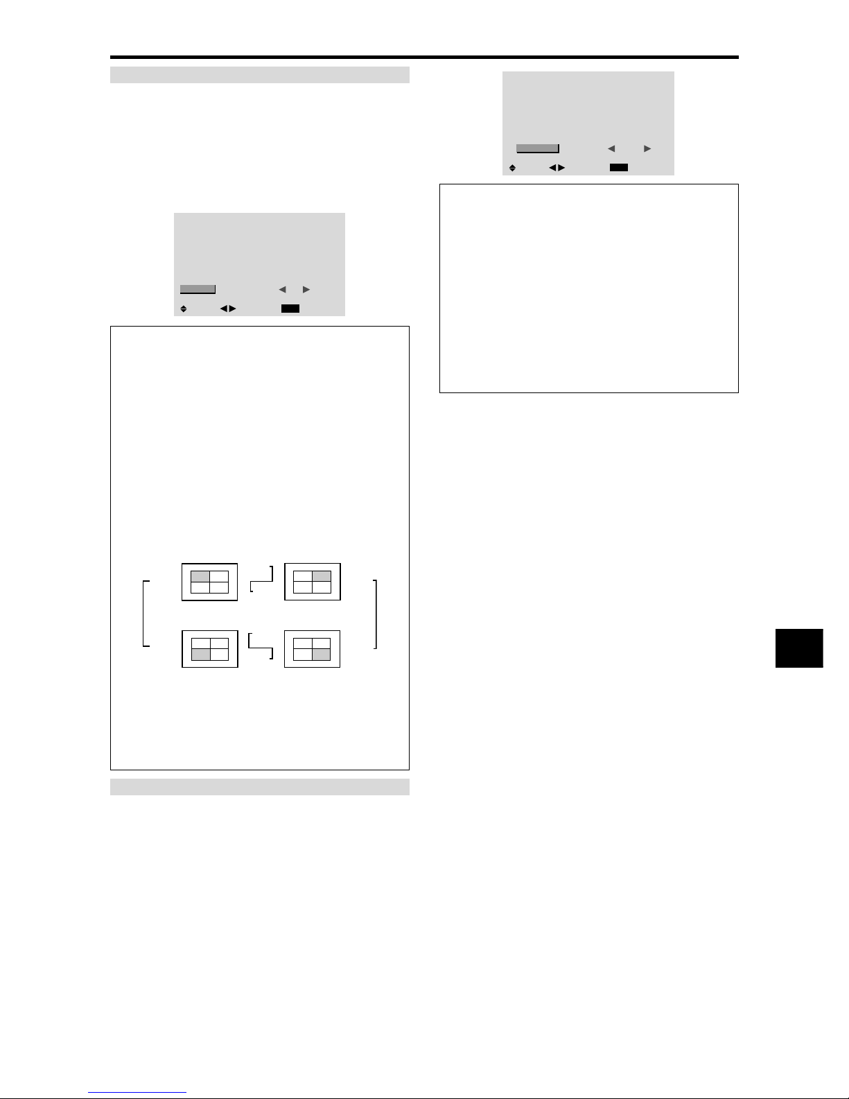
E-31
PLE LINK
Use this function to set a uniform brightness for each
display.
Turn on the AUT O ID and set the DIVIDER (at 1, 4 or 9)
before the following operations.
Example: Setting “ON”
On “PLE LINK” of “VIDEO WALL” menu, select “ON”,
then press the MENU/ENTER button.
VIDEO WALL
EXIT
DIVIDER
POSITION
DISP. MODE
AUTO ID
IMAGE ADJUST
P. ON DELAY
PLE LINK
REPEAT TIMER
: 1
: SPLIT
: OFF
: OFF
: ON
: OFF
SEL.
RETURN
ADJ.
Information
䡵 PLE LINK settings
ON: Sets a uniform brightness for each screen in a video
wall. This can be set only when a 2×2 or 3×3 video
wall is selected.
OFF: Sets the individual screen brightness for each
screen in a video wall.
* When this function is set “ON”, connect your plasma
displays with the remote cable (optional) in the order of
the position numbers for the 2×2 video wall. See the
drawing below.
* If there are changes in the DIVIDER or POSITION,
the PLE LINK will automatically turn OFF .
REMOTE
IN
REMOTE
IN
REMOTE
OUT
REMOTE
OUT
REMOTE
IN
REMOTE
OUT
REMOTE
OUT
REMOTE
IN
No.1
No.2
No.3No.4
No.1
No.2
No.3No.4
No.1
No.2
No.3No.4
No.1
No.2
No.3No.4
Display 1
Display 2
Display 4
Display 3
* With the 3×3 video wall, connect the final display to
the first display the same way as with 2×2 video wall.
Note:
The remote control can be operated unless the
IR REMOTE is set to “OFF”.
REPEA T TIMER
Use this to set two timers. Each timer can use the
DIVIDER, SOURCE and WORK TIME.
Turn on the AUT O ID and set the DIVIDER (at 1, 4 or 9)
before the following operations.
Example:
TIMER1...VIDEO1 will be displayed for 3 minutes.
TIMER2...RGB1 will be displayed for 6 minutes in a
2×2 video wall.
On “REPEAT TIMER” of “VIDEO WALL” menu, select
“ON”, then press the MENU/ENTER button.
The “REPEAT TIMER” screen appears.
Adjust the items.
REPEAT TIMER
EXIT
1 DIVIDER
SOURCE
WORK TIME
2 DIVIDER
SOURCE
WORK TIME
: 1
: VIDEO1
: 00H03M
: 4
: RGB1
: 00H06M
SEL.
RETURN
ADJ.
Information
䡵 REPEAT TIMER settings
DIVIDER: Divide the screen into 1, 4 or 9 sections.
SOURCE: Set the input mode to be displayed.
WORK TIME: Can be set to up to 4 hours 15 minutes
in units of 1 minute.
If you set both timers, Timer 1 and Timer 2 run
consecutively.
In the case of the V ideo wall, timer No.1 can be used to
control all the displays simultaneously.
* This becomes effective when the on-screen menu goes
out.
Page 36
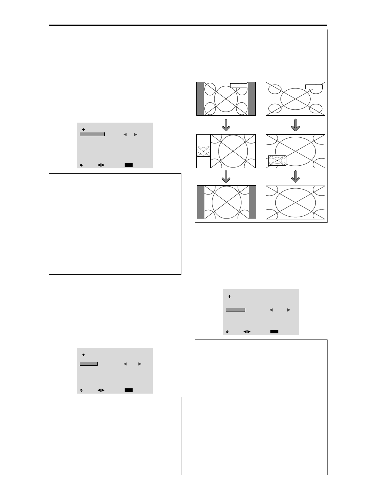
E-32
Option4 Settings Menu
Erasing the sub screen image when there is
no input signal
This function automatically erases the black frame of the
sub screen when there is no sub screen input signal.
This feature is available only when the picuture-in-picuture
mode is selected.
Example: Set to “OFF”
Set “ADVANCED OSM” to “ON” in the main menu (1/
2), then perform the following operations.
On “SUB. P DETECT” of “OPTION4” menu, select
“OFF”.
OPTION4
4 / 4
EXIT
PREVIOUS PAGE
SUB. P DETECT
ZOOM NAV
PIC FREEZE
SEAMLESS SW
SELECT1
SELECT2
: OFF
: BTM LFT
: S BY S
: OFF
: —
: —
SEL.
RETURN
ADJ.
Information
䡵 SUB. P DETECT Function
* The sub screen disappears when the input signal is lost.
* Loss of the input signal means a condition in which the
video signal and the sync signal are not present.
* Under conditions in which the sub screen has
disappeared, the ZOOM NAV, PIC FREEZE, and
SEAMLESS SW functions will not work. The WIDE
button will not function either.
䡵 SUB. P DETECT settings
AUTO: The black frame disappears 3 seconds after the
input signal is lost.
OFF: Turns off the SUB. P DETECT function.
RGB/PC1
RGB/PC1
Side-by-Side Picture-in-Picture
POINTER button
or
Zoom+/- button
POINTER button
Displaying still images in the sub screen
This feature enables display in the sub screen of still images
captured by pressing the SELECT/FREEZE button.
Example: Setting “PIC FREEZE” to “BTM LFT”
Set “ADVANCED OSM” to “ON” in the main menu (1/
2), then perform the following operations.
On “PIC FREEZE” of “OPTION4” menu, select “BTM
LFT”.
OPTION4
4 / 4
EXIT
PREVIOUS PAGE
SUB. P DETECT
ZOOM NAV
PIC FREEZE
SEAMLESS SW
SELECT1
SELECT2
: AUTO
: BTM LFT
: BTM LFT
: OFF
: —
: —
SEL.
RETURN
ADJ.
Information
䡵 PIC FREEZE Function
* This feature is available only for RGB1 or RGB2 input
signals.
* This feature does not function during split screen mode.
* Digital zoom is not available while this function is
operating.
* A further press of the SELECT/FREEZE button while
this function is operating will cancel this function.
* Providing a 2-screen display will cancel this function.
䡵 PIC FREEZE settings
OFF: Will not show the still image.
S BY S1, 2: The still images captured by pressing the
SELECT/FREEZE button will be shown on the sub
screen of side-by-side mode.
BTM LFT~TOP LFT: The still images captured by
pressing the SELECT/FREEZE button will be shown
on the sub screen of picture-in-picture mode.
䡵 ZOOM NAV settings
OFF: Will not show the entire image on the sub screen.
S BY S: Will show the entire image on the sub screen
of side-by-side mode.
BTM LFT~TOP LFT: Will show the entire image on
the sub screen of picture-in-picture mode.
Displaying the entire image during DIGITAL
ZOOM operations
Use this function to display the entire image within the
sub screen together with an enlarged image on the main
screen.
Example: Setting “ZOOM NAV” to “S BY S”
Set “ADVANCED OSM” to “ON” in the main menu (1/
2), then perform the following operations.
On “ZOOM NAV” of “OPTION4” menu, select “S BY S ”.
OPTION4
4 / 4
EXIT
PREVIOUS PAGE
SUB. P DETECT
ZOOM NAV
PIC FREEZE
SEAMLESS SW
SELECT1
SELECT2
: AUTO
: S BY S
: S BY S
: OFF
: —
: —
SEL.
RETURN
ADJ.
Information
䡵 ZOOM NAV Function
* This feature is available only for RGB1 or RGB2 input
signals.
* This feature does not function during split screen mode.
* This feature does not function while PIC FREEZE is
operating.
* Providing a 2-screen display will cancel this function.
Page 37
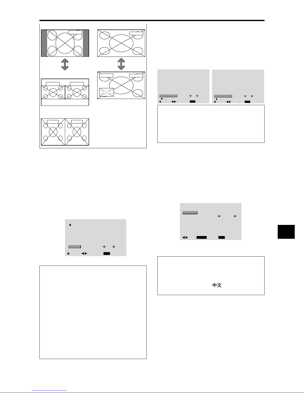
E-33
Switching the input source quickly
This feature enables quick input selection.
After setting ON, press the CLEAR/SEAMLESS SW
button for quick switching between the two selected input
signals.
Example: Set to switch quickly between RGB1 and
RGB2.
Set “ADVANCED OSM” to “ON” in the main menu (1/
2), then perform the following operations.
On “SEAMLESS SW” of “OPTION4” menu, select “ON”.
Select “RGB1” and “RGB2”.
OPTION4
4 / 4
EXIT
PREVIOUS PAGE
SUB. P DETECT
ZOOM NAV
PIC FREEZE
SEAMLESS SW
SELECT1
SELECT2
: AUTO
: BTM LFT
: S BY S
: ON
: RGB1
: RGB2
SEL.
RETURN
ADJ.
* The available sources depend on the settings of input.
Information
䡵 SEAMLESS SW Function
* This feature will not function for certain input
combinations. See the table on page E-13.
* After switching to the selected input, please operate this
function.
* This feature will not function during split screen mode.
* When SEAMLESS SW is first turned on, or when
signals being transmitted are changed, there may be a
slight delay due to signal analysis.
䡵 SEAMLESS SW settings
OFF: Turns off the SEAMLESS SW function.
ON: When the CLEAR/SEAMLESS SW button is
pressed, input signals will switch quickly according to
the setting of SELECT1 and SELECT2.
RGB/PC1
RGB/PC1
RGB/PC1
RGB/PC1
RGB/PC1
RGB/PC1
Side-by-Side Picture-in-Picture
SELECT/
FREEZE
button
Advanced OSM Settings Menu
Setting the menu mode
This allows you to access full menu items.
When P. ON DELAY or PLE LINK is ON, this won’t be
turned OFF.
Example: Setting “ON”
On “ADVANCED OSM” of “MAIN MENU”, select “ON”.
MAIN MENU
1 / 2
EXIT
PICTURE
AUDIO
IMAGE ADJUST
OPTION1
ADVANCED OSM
NEXT PAGE
:
OFF
SEL.
EXIT
ADJ.
MAIN MENU
1 / 2
EXIT
PICTURE
AUDIO
IMAGE ADJUST
OPTION1
OPTION2
OPTION3
OPTION4
ADVANCED OSM
NEXT PAGE
:
ON
SEL.
EXIT
ADJ.
Information
䡵 ADVANCED OSM settings
ON: All of the main menu items are available for
advanced users.
OFF: Some of the main menu items are not available
(e.g. OPTION2, OPTION3 and OPTION4).
Language Settings Menu
Setting the language for the menus
The menu display can be set to one of eight languages.
Example: Setting the menu display to “DEUTSCH”
On “MAIN MENU”, select “LANGUAGE”, then press the
MENU/ENTER button.
The “LANGUAGE” screen appears.
On “LANGUAGE”, select “ DEUTSCH”, then press the
MENU/ENTER button.
LANGUAGE
MENU/ENTER
EXIT
LANGUAGE
: DEUTSCH
RETURN
OK
ADJ.
The “LANGUAGE” is set to “DEUTSCH” and return to the
main menu.
Information
䡵 Language settings
ENGLISH ........English
DEUTSCH.......German
FRANÇAIS...... French
ESPAÑOL .......Spanish
ITALIANO ........Italian
SVENSKA .......Swedish
...................Chinese
У ............Russian
SELECT/
FREEZE
button
S BY S1
RGB/PC1
RGB/PC1
or
S BY S2
Page 38
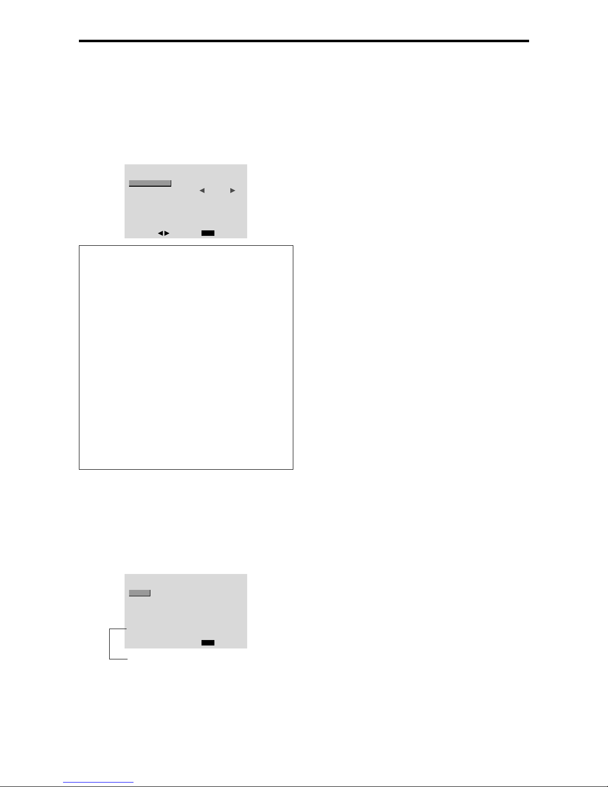
E-34
Color System Settings Menu
Setting the video signal format
Use these operations to set the color systems of composite
video signals or Y/C input signals.
Example: Setting the color system to “3.58 NTSC”
On the MAIN MENU, select “COLOR SYSTEM”, then press
the MENU/ENTER button.
The “COLOR SYSTEM” screen appears.
On “COLOR SYSTEM”, select “ 3.58NTSC ”.
COLOR SYSTEM
EXIT
COLOR SYSTEM
: 3.58NTSC
RETURN
ADJ.
Information
䡵 Video signal formats
Different countries use different formats for video
signals. Set to the color system used in your current
country.
AUTO: The color systems are automatically identified
and the format is set accordingly.
PAL: This is the standard format used mainly in the
United Kingdom and Germany.
SECAM: This is the standard format used mainly in
France and Russia.
4.43 NTSC, PAL60: This format is used for videos in
countries using PAL and SECAM video signals.
3.58 NTSC: This is the standard format used mainly
in the United States and Japan.
PAL-M: This is the standard format used mainly in
Brazil.
PAL-N: This is the standard format used mainly in
Argentina.
Source Information Menu
Checking the frequencies, polarities of input
signals, and resolution
Use this function to check the frequencies and polarities
of the signals currently being input from a computer, etc.
On “MAIN MENU”, select “SOURCE INFORMATION”,
then press the MENU/ENTER button.
The “SOURCE INFORMATION” is displayed.
SOURCE INFORMATION
EXIT
H. FREQ
V. FREQ
H. POLARITY
V. POLARITY
MEMORY
RESOLUTION
: 48.4KHZ
: 60.0HZ
: NEG.
: NEG.
: 24
: 1024×768
RETURN
PC: MEMORY will be displayed.
Others: MODE will be displayed.
Page 39
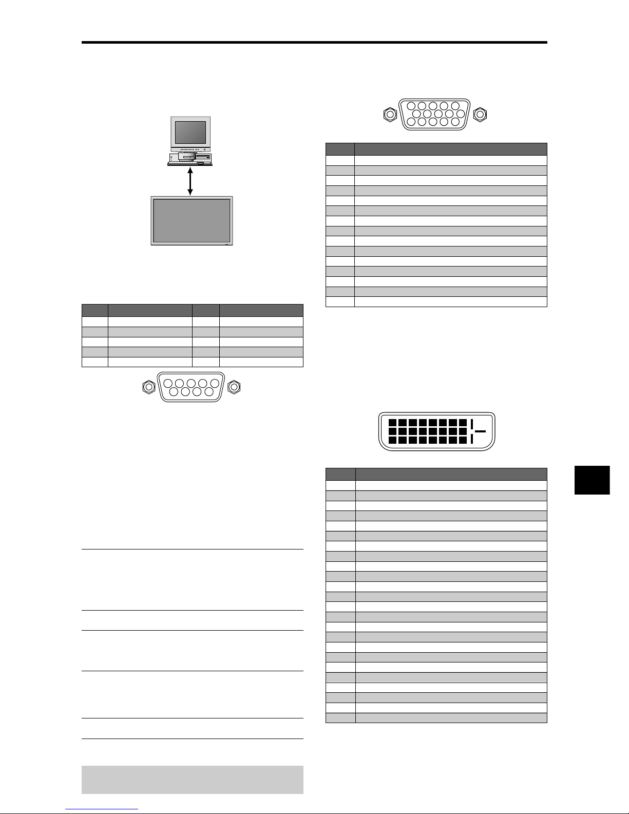
E-35
Application
These specifications cover the communications control of
the plasma monitor by external equipment.
Connections
Connections are made as described below.
Connector on the plasma monitor side: EXTERNAL
CONTROL connector.
Use a crossed (reverse) cable.
Type of connector: D-Sub 9-pin male
1
5
9
6
2
34
7
8
Communication Parameters
(1) Communication system Asynchronous
(2) Interface RS-232C
(3) Baud rate 9600 bps
(4) Data length 8 bits
(5) Parity Odd
(6) Stop bit 1 bit
(7) Communication code Hex
External Control Codes (Reference)
FUNCTION CODE DATA
Power ON 9FH 80H 60H 4EH 00H CDH
OFF 9FH 80H 60H 4FH 00H CEH
Input Switch Video1 (BNC) DFH 80H 60H 47H 01H 01H 08H
Video2 (RCA) DFH 80H 60H 47H 01H 02H 09H
Video3 (S-Video) DFH 80H 60H 47H 01H 03H 0AH
DVD1/HD1 (RCA) DFH 80H 60H 47H 01H 05H 0CH
DVD2/HD2 (BNC) DFH 80H 60H 47H 01H 06H 0DH
RGB1 (mini D-Sub 15-Pin) DFH 80H 60H 47H 01H 07H 0EH
RGB2 (5BNC) DFH 80H 60H 47H 01H 08H 0FH
RGB3 (DVI) DFH 80H 60H 47H 01H 0CH 13H
Audio Mute ON 9FH 80H 60H 3EH 00H BDH
OFF 9FH 80H 60H 3FH 00H BEH
Picture Mode NORMAL DFH 80H 60H OAH 01H 01H CBH
THEAT. 1 DFH 80H 60H OAH 01H 02H CCH
THEAT. 2 DFH 80H 60H OAH 01H 03H CDH
DEFAULT DFH 80H 60H OAH 01H 04H CEH
BRIGHT DFH 80H 60H OAH 01H 05H CFH
Screen Mode STADIUM DFH 80H 60H 51H 01H 02H 13H
ZOOM DFH 80H 60H 51H 01H 03H 14H
NORMAL DFH 80H 60H 51H 01H 04H 15H
FULL DFH 80H 60H 51H 01H 05H 16H
14 : 9 DFH 80H 60H 51H 01H 09H 1AH
2.35 : 1 DFH 80H 60H 51H 01H 0AH 1BH
Auto Picture ON DFH 80H 60H 7FH 03H 03H 09H 00H 4DH
OFF DFH 80H 60H 7FH 03H 03H 09H 01H 4EH
Cinema Mode ON DFH 80H 60H C1H 01H 01H 82H
OFF DFH 80H 60H C1H 01H 02H 83H
Note:
Contact your local dealer for a full list of the
External Control Codes if needed.
Display
External equipment
e.g., Personal computer
Pin Name
No Connection
RXD (Receive data)
TXD (Transmit data)
DTR (DTE side ready)
GND
Pin No.
1
2
3
4
5
Pin No.
6
7
8
9
Pin Name
DSR (DCE side ready)
RTS (Ready to send)
CTS (Clear to send)
No connection
5 4 3 2 1
15 14 13 12 11
10 9 8 7 6
RGB 1
Signal (Analog)
Red
Green or sync-on-green
Blue
No connection
Ground
Red ground
Green ground
Blue ground
No connection
Sync signal ground
No connection
Bi-directional DATA (SDA)
Horizontal sync or Composite sync
Vertical sync
Data clock
Pin No.
1
2
3
4
5
6
7
8
9
10
11
12
13
14
15
12345678
910111213141516
20191817 21 22 23 24
RGB 3
Pin No.
1
2
3
4
5
6
7
8
9
10
11
12
13
14
15
16
17
18
19
20
21
22
23
24
Signal (Digital)
T.M.D.S Data 2 T.M.D.S Data 2 +
T.M.D.S Data 2 Shield
No connection
No connection
DDC Clock
DDC Data
No connection
T.M.D.S Data 1 T.M.D.S Data 1 +
T.M.D.S Data 1 Shield
No connection
No connection
+5V Power
Ground
Hot Plug Detect
T.M.D.S Data 0 T.M.D.S Data 0 +
T.M.D.S Data 0 Shield
No connection
No connection
T.M.D.S Clock Shield
T.M.D.S Clock +
T.M.D.S Clock -
External Control
mini D-Sub 15-pin connector
(Analog)
DVI-D 24-pin connector (Digital)
The unit is equipped with a type of connector commonly
used for digital.
(This cannot be used for an analog input.)
(TMDS can be used for one link only.)
Pin Assignments
Page 40
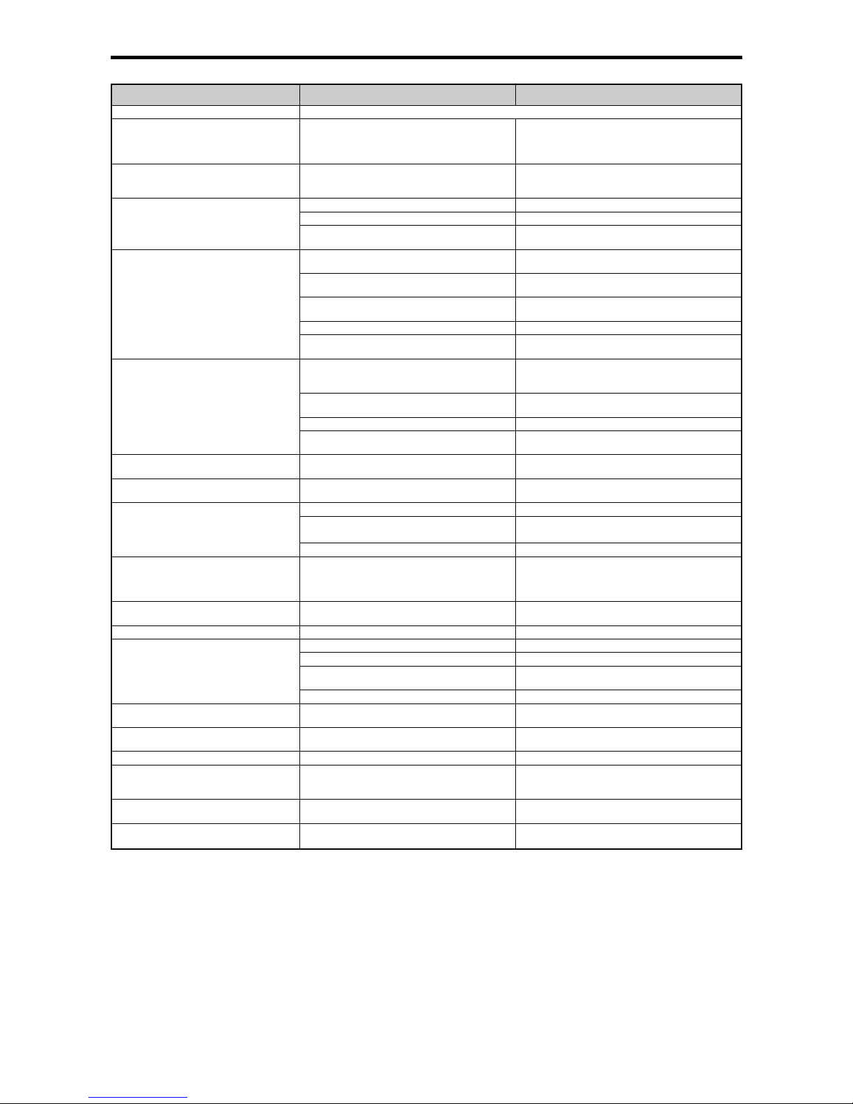
E-36
If the picture quality is poor or there is some other problem, check the adjustments, operations, etc., before requesting service.
Troubleshooting
*1 Overheat protector
If the monitor becomes too hot, the overheat protector will be activated and the monitor will be turned off. If this happens, turn off the power to the monitor
and unplug the power cord. If the room where the monitor is installed is particularly hot, move the monitor to a cooler location and wait for the monitor
to cool for 60 minutes. If the problem persists, contact your dealer.
*2 In the following case, power off the monitor immediately and contact your dealer or authorized Service Center.
The monitor turns off 5 seconds after powering on and then the POWER/STANDBY indicator blinks. It indicates that the power supply circuit, plasma
display panel, temperature sensor, or one or more fans have been damaged.
Remedy
• If there are no abnormalities in the image and sound,
the noise is caused by the cabinet reacting to
changes in temperature. This will not affect
performance.
• Leave some space between the display and the
connected components.
• Replace both batteries with new ones.
• Set IR REMOTE OFF on OPTION3 menu.
• Set an ID number with the ID SELECT button, or set
the ID number to ALL.
• Plug the monitor’s power cord into a power outlet.
• Press the power button on the monitor to turn on the
power.
• Replace both batteries with new ones.
• Set IR REMOTE ON.
• Set an ID number with the ID SELECT button, or set
the ID number to ALL.
• Point the remote control at the monitor’s remote
control sensor when pressing buttons, or remove the
obstacle.
• Eliminate the light by closing curtains, pointing the
light in a different direction, etc.
• Replace both batteries with new ones.
• Unplug the remote cable from the monitor.
• Set the Control Lock to OFF.
• Plug the monitor’s power cord into a power outlet.
• Increase the volume.
• Press the remote control’s MUTE button.
• Connect the speakers properly.
• Set AUDIO INPUT on the AUDIO menu correctly.
• Adjust picture control as needed.
Try another location for the monitor.
Be sure all connections are secure.
• Adjust picture controls as needed.
Check pin assignments and connections.
• Adjust the tint and color (under PICTURE).
• Turn on the computer’s power.
• Connect source to the monitor.
• Operate the computer (move the mouse, etc.).
• Set LOOP OUT OFF.
• Adjust the IMAGE ADJUST properly.
• Press the WIDE button on the remote control and
adjust properly.
• Set to the proper resolution.
• Check the input signal.
• Promptly switch off the power of the main unit and
wait until the internal temperature drops. See*1.
• Prompty switch off the power of the main unit. See
*2.
• Maybe the sound from the cooling fans used to prevent over heating.
Symptom
Mechanical sound is heard.
The unit emits a crackling sound.
Picture is disturbed.
Sound is noisy.
Remote control operates erroneously.
The remote control does not work.
Monitor’s power does not turn on when the
remote control’s power button is pressed.
Monitor does not operate when the remote
control’s buttons are pressed.
The front panel buttons of the main unit do
not function.
No sound or picture is produced.
Picture appears but no sound is produced.
Poor picture with VIDEO signal input.
Poor picture with RGB signal input.
Tint is poor or colors are weak.
Nothing appears on screen.
Part of picture is cut off or picture is not
centered.
Image is too large or too small.
Picture is unstable.
POWER/STANDBY indicator is lighted in red.
POWER/STANDBY indicator is blinking in
red.
POWER/STANDBY indicator is blinking in
green and red, or green.
Checks
• Are the image and sound normal?
• Is a connected component set directly in front or at
the side of the display?
• Are the remote control’s batteries worn out?
• Is IR REMOTE set to ON?
• Has an ID number been set for the main unit?
• Is the monitor’s power cord plugged into a power
outlet?
• Are all the monitor’s indicators off?
• Are the remote control’s batteries worn out?
• Is IR REMOTE set to OFF?
• Has an ID number been set for the main unit?
• Is the remote control pointed at the monitor, or is
there an obstacle between the remote control and
the monitor?
• Is direct sunlight or strong artificial light shining on
the monitor’s remote control sensor?
•
Are the remote control’s batteries worn out?
• The remote cable is plugged into the REMOTE IN
terminal (Wired).
• The front panel buttons do not function during
Control Lock.
• Is the monitor’s power cord plugged into a power
outlet?
• Is the volume set at the minimum?
• Is the mute mode set?
• Are the speakers properly connected?
• Is AUDIO INPUT set correctly?
• Improper control setting.
Local interference.
Cable interconnections.
Input impedance is not correct level.
• Improper control setting.
Incorrect 15 PIN connector pin connections.
• Are the tint and colors properly adjusted?
• Is the computer’s power turned on?
• Is a source connected?
• Is the power management function in the standby
or off mode?
• Is LOOP OUT set to ON?
• Is the position adjustment appropriate?
• Is the screen size adjustment appropriate?
• Is the computer’s resolution setting appropriate?
• Horizontal and / or vertical sync signal is not
present when the Intelligent Power Manager
control is on.
• The temperature inside the main unit has become
too high and has activated the protector.
——————
 Loading...