

NEC PlasmaSync 42XP10, PlasmaSync 50XP10, PlasmaSync 60XP10, P42XP10, P50XP10 User Manual
...Page 1

PlasmaSync 42XP10
PlasmaSync 50XP10
PlasmaSync 60XP10
EXIT MUTEINPUT
English
User’s Manual
Page 2

Package Contents
Plasma Monitor
Remote control and AA Batteries
Power cord
Users Manual (CD-ROM)
Start Up Guide (Paper / CD-ROM)
Main Power Switch cover and screw
Cable clamps
•
•
•
•
•
•
•
Page 3

Important Safety Instructions ..............................................................................................................English-1
Important Information ...........................................................................................................................English-2
Safety Precautions and Maintenance ...................................................................................................English-3
Recommended Use ....................................................................................................................................English-4
Installation
Using Optional Stands/Mounts ...............................................................................................English-6
Mounting Location ....................................................................................................................English-6
Mounting on Ceiling ..................................................................................................................English-7
Maintenance, Orientation, Cable Management ..................................................................English-7
Using the Remote ......................................................................................................................English-8
Part Names and Functions
Control Panel ..............................................................................................................................English-9
Terminal Panel ............................................................................................................................English-10
Remote Control Functions .......................................................................................................English-11
Power, Display, Digital Zoom, Pointer, Main Power Switch Cover .....................................English-12
Remote Control ID .....................................................................................................................English-13
On-Screen Display (OSD)
Using the OSD .............................................................................................................................English-14
OSD ................................................................................................................................................English-15
Operation
Picture Size Using Video Signals ............................................................................................English-19
Picture Size Using Computer Signals ....................................................................................English-20
Split Screen Mode .....................................................................................................................English-21
Picture in Picture Mode ...........................................................................................................English-22
Creating a Video Wall ................................................................................................................English-23
Using the Timer..........................................................................................................................English-24
Repeat Timer ..............................................................................................................................English-25
RS-232C .......................................................................................................................................................English-26
Troubleshooting.........................................................................................................................................English-30
Specifi cations
P42XP10 .......................................................................................................................................English-31
P50XP10 .......................................................................................................................................English-32
P60XP10 .......................................................................................................................................English-33
Supported Resolutions
P42XP10 .......................................................................................................................................English-34
P50XP10 .......................................................................................................................................English-36
P60XP10 .......................................................................................................................................English-38
Pin Assignment ..........................................................................................................................................English-40
Table of Contents
Page 4

English-1
Read Before Operating Equipment.
1. Read these instructions.
2. Keep these instructions.
3. Heed all warnings.
4. Follow all instructions.
5. Do not use this apparatus near water.
6. Clean only with a dry cloth.
7. Do not block any of the ventilation openings. Install in
accordance with the manufacturer's instructions.
8. Do not install near any heat sources such as radiators,
heat registers, stoves, or other apparatus (including
ampli ers) that produce heat.
9. Do not defeat the safety purpose of the polarized or
grounding-type plug. A polarized plug has two blades
with one wider than the other. A grounding type plug
has two blades and third grounding prong e wide
blade or third prong are provided for your safety. If the
provided plug does not t into your outlet, consult an
electrician for replacement of the obsolete outlet.
10. Protect the power cord from being walked on or
pinched particularly at plugs, convenience receptacles,
and the point where they exit from the apparatus.
11. Only use attachments/accessories speci ed by the
manufacturer
12. Use only with the cart, stand, tripod, bracket, or
table speci ed by the manufacturer, or sold with the
apparatus. When a cart is used, use caution when
moving the cart or apparatus combination to avoid
injury from tip-over.
13. Unplug this apparatus during lightning storms or when
unused for long periods of time
14. Refer all servicing to quali ed service personnel.
Servicing is required when the apparatus has been
damaged in any way, such as when the power-supply
cord or plug is damaged, liquid has been spilled or
objects have fallen into the apparatus, the apparatus
has been exposed to rain or moisture, does not operate
normally, or has been dropped
Additional Safety Information
15. is product may contain lead. Disposal of these
materials may be regulated due to environmental
considerations.
For disposal or recycling information, please contact
your local authorities or the Electronic Industries
Alliance: www.eiae org.
16. Damage Requiring Service - e appliance should be
serviced by quali ed service personnel when:
A. e power supply cord or the plug has been damaged;
or
B. Objects have fallen, or liquid has been spilled into
the appliance;
or
C. e appliance has been exposed to rain;
or
D. e appliance does not appear to operate normally or
exhibits a marked change in performance;
or
E. e appliance has been dropped, or the enclosure
damaged.
17. Tilt/Stability - All monitors must comply with
recommended international global safety standards for
tilt and stability properties of its cabinet design.
Do not compromise these design standards by applying
excessive pull force to the front, or top, of the cabinet
which could ultimately overturn the product.
Also, do not endanger yourself, or children, by placing
electronic equipment/toys on the top of the cabinet.
Such items could unsuspectingly fall from the top of the
set and cause product damage and/or personal injury.
18. Wall/Ceiling Mounting - e appliance should be
mounted to a wall/ceiling only as recommended by the
manufacturer.
19. Power Lines - An outdoor antenna should be located
away from power lines.
20. Outdoor Antenna Grounding - If an outside antenna is
connected to the receiver, be sure the antenna system
is grounded so as to provide some protection against
voltage surges and built up static charges.
Section 810 of the National Electric code. ANSI/NFPA
No.70-1984, provides information with respect to
proper grounding of the mats and supporting structure,
grounding of the lead-in wire to an antenna-discharge
unit, size of grounding connectors, location of antenna
discharge unit, connection to grounding electrodes and
requirements for the grounding electrode.
21. Objects and Liquid Entry - Care should be taken so that
objects do not fall and liquids are not spilled into the
enclosure through openings.
Apparatus shall not be exposed to dripping or splashing
and no objects lled with liquids, such as vases, shall be
placed on apparatus
WA R N I N G
To reduce t he risk of re or electric shock, do not expose
this apparatus to rain or moisture.
Important Safety Instructions
Page 5
English
English-2
WARNING
TO PREVENT FIRE OR SHOCK HAZARDS, DO NOT EXPOSE THIS UNIT TO RAIN OR MOISTURE. DO NOT USE THIS
UNIT’S POLARIZED PLUG WITH AN EXTENSION CORD RECEPTACLE OR OTHER OUTLETS UNLESS THE PRONGS
CAN BE FULLY INSERTED.
REFRAIN FROM OPENING THE CABINET AS THERE ARE HIGH VOLTAGE COMPONENTS INSIDE. REFER SERVICING
TO QUALIFIED SERVICE PERSONNEL.
CAUTION
CAUTION: TO REDUCE THE RISK OF ELECTRIC SHOCK, MAKE SURE POWER CORD IS UNPLUGGED FROM WALL
SOCKET. TO FULLY DISENGAGE THE POWER TO THE UNIT, PLEASE DISCONNECT THE POWER CORD
FROM THE AC OUTLET. DO NOT REMOVE COVER (OR BACK). NO USER SERVICEABLE PARTS INSIDE.
REFER SERVICING TO QUALIFIED SERVICE PERSONNEL.
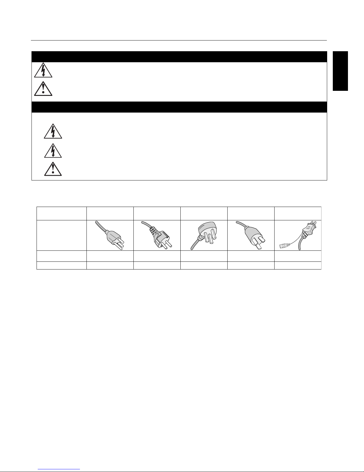
is symbol warns user that uninsulated voltage within the unit may have su cient magnitude to cause electric shock.
erefore, it is dangerous to make any kind of contact with any part inside this unit.
is symbol alerts the user that important literature concerning the operation and maintenance of this unit has been
included. erefore, it should be read carefully in order to avoid any problems.
Important Information
Canadian Department of
Communications Compliance Statement
DOC: is Class B digital apparatus meets all requirements of the Canadian
Interference-Causing Equipment Regulations.
C-UL: Bears the C-UL Mark and is in compliance with Canadian Safety
Regulations according to CAN/CSA C22.2
No. 60950-1.
FCC Information
1. Use the attached speci ed cables with the P426Y0(P42XP10),
P506Y1(P50XP10), or P606Y2(P60XP10) color monitor so as not to
interfere with radio and television reception.
(1) Please use the supplied power cord or equivalent to
ensure FCC compliance.
(2) Please use shielded video signal cable,
15-pin mini D-SUB to 15-pin mini D-SUB
with ferrite cores on both ends (not included).
2. is equipment has been tested and found to comply with the limits
for a Class B digital device, pursuant to part 15 of the FCC Rules. ese
limits are designed to provide reasonable protection against harmful
interference in a residential installation. is equipment generates, uses,
and can radiate radio frequency energy, and, if not installed and used
in accordance with the instructions, may cause harmful interference to
radio communications. However, there is no guarantee that interference
will not occur in a particular installation. If this equipment does cause
harmful interference to radio or television reception, which can be
determined by turning the equipment o and on, the user is encouraged
to try to correct the interference by one or more of the following
measures:
Reorient or relocate the receiving antenna.
Increase the distance between the equipment and
receiver.
Connect the equipment into an outlet on a circuit
di erent from that to which the receiver is connected.
Consult your dealer or an experienced radio/TV technician for help.
If necessary, the user should contact the dealer or an experienced radio/
television technician for additional suggestions. e user may nd the
following booklet, prepared by the Federal Communications Commission,
helpful: “How to Identify and Resolve Radio-TV Interference Problems.” is
booklet is available from the U.S. Government Printing O ce, Washington,
D.C., 20402, Stock No. 004-000-00345-4.
WA R N I N G
is product equipped with a three-wire grounding (earthed) plug - a plug
that has a third (grounding) pin. is plug only ts a grounding-type power
outlet. If you are unable to insert the plug into an outlet, contact a licensed
electrician to replace the outlet with a properly grounded one. Do not defeat
the safety purpose of the grounding plug.
•
•
•
•
CAUTION: Please use the power cord provided with this display in accordance with the table below. If a power cord is not
supplied with this equipment, please contact your supplier. For all other cases, please use a power cord that matches the AC
voltage of the power outlet and has been approved by and complies with the safety standard of your particular country.
Plug Type North America
European
Continental
U.K. Chinese Japanese
Plug Shape
Country
Voltage
U.S.A./Canada U.K. China JapanEU (except U.K.)
120* 230 220 100230
*When operating the PlasmaSync monitor with its AC 125-240V power supply, use a power supply cord that matches the power
supply voltage of the AC power outlet being used.
Page 6

English-3
Safety Precautions and Maintenance
Safety Precautions
and Maintenance
FOR OPTIMUM PERFORMANCE, PLEASE NOTE
THE FOLLOWING WHEN SETTING UP AND
USING THE MONITOR:
e plasma display's panel is made up of ne picture
elements (cells), of which more than 99.99 percent are active
cells. Some cells may not produce light or remain constantly
lit. For safe operation and to avoid damaging the unit, read
carefully and observe the following instructions.
DO NOT OPEN THE MONITOR. ere are no userserviceable parts inside and opening or removing covers
may expose you to dangerous shock hazards or other
risks. e manufacturer is not liable for any bodily harm
or damage caused if unquali ed persons attempt service
or open the back cover. Refer all servicing to quali ed
service personnel.
Do not spill any liquids into the cabinet or use your
monitor near water.
Do not insert objects of any kind into the cabinet slots,
as they may touch dangerous voltage points, which can
be harmful or fatal or may cause electric shock, re or
equipment failure.
Do not bend, crimp or otherwise damage the power cord.
Do not place any heavy objects on the power cord.
Damage to the cord may cause shock or re.
Do not place this product on a sloping or unstable cart,
stand or table, as the monitor may fall, causing serious
damage to the monitor.
Do not use in a moving vehicle, as the unit could drop or
topple over and cause injuries.
e power cable connector is the primary means of
detaching the system from the power supply. e
monitor should be installed close to a power outlet that
is easily accessible.
is equipment shall be connected to a MAIN outlet
with a protective earth-ground connection. Do not place
any objects onto the monitor and do not use the monitor
outdoors.
Do not use this unit’s polarized plug with an extension
cord or with outlets unless the prongs can be inserted
fully.
e power supply cord you use must have been approved
by and comply with the safety standards of your
country. (Type H05VV-F 3G 1mm2 should be used in
Europe)
In UK, use a BS-approved power cord with molded plug
having a black (13A) fuse installed for use with this
monitor.
Use only with 100 V to 240 V 50 Hz/60 Hz AC power
supply. Continued operation at line voltages greater than
100 V to 240 V AC will shorten the life of the unit, and
might even cause a re hazard.
•
•
•
•
•
•
•
•
•
•
•
•
Unplug the power cord during electrical storms or when
the unit will not be in use for a long period.
Do not use monitor in high temperature, humid, dusty,
or oily areas.
Do not cover vent on monitor.
Clean plasma ventilation areas using a vacuum cleaner
with a so brush nozzle attachment.
To ensure proper ventilation, cleaning the ventilation
areas must be carried out monthly. More frequent
cleaning may be necessary depending on the
environment in which the plasma monitor is installed.
Allow adequate ventilation around the monitor so that
heat can properly dissipate. Do not block ventilated
openings or place the monitor near a radiator or other
heat sources. Do not put anything on top of monitor.
Handle with care when transporting. Save packaging for
transporting.
As is the case with any phosphor-based display (like a
CRT monitor, for example) light output will gradually
decrease over the life of a Plasma Display Panel.
To avoid sulfurization it is strongly recommended not to
place the unit in a dressing room in a public bath or hot
spring bath.
CAUTION
Immediately unplug your monitor from the wall outlet and
refer servicing to quali ed service personnel under the
following conditions:
When the power supply cord or plug is damaged.
If liquid has been spilled on, or objects have fallen into
the monitor.
If the monitor has been exposed to rain or water.
If the monitor has been dropped or the cabinet
damaged.
If the monitor does not operate normally by following
operating instructions.
•
•
•
•
•
•
•
•
•
•
•
•
•
•
Page 7

English
English-4
CAUTION
CORRECT PLACEMENT AND ADJUSTMENT OF
THE MONITOR CAN REDUCE EYE, SHOULDER AND
NECK FATIGUE. CHECK THE FOLLOWING WHEN
POSITIONING THE MONITOR:
For optimum performance, allow 20 minutes for warmup.
Rest your eyes periodically by focusing on an object at
least 5 feet away. Blink o en.
Position the monitor at a 90 degree angle to windows
and other light sources to minimize glare and
re ections.
Clean the monitor surface with a lint-free, nonabrasive
cloth. Avoid using any cleaning solution or glass
cleaner.
Adjust the monitor’s brightness and contrast controls to
enhance readability.
Get regular eye checkups.
Ergonomics
To realize the maximum ergonomic bene ts, we recommend
the following:
Use the preset Size and Position controls with standard
signals.
Use the preset Color Setting.
Do not use primary color blue on a dark background, as
it is di cult to see and may produce eye fatigue due to
insu cient contrast.
is equipment is not for use at video display work
station according to Bildscharb V.
For more detailed information on setting up a healthy work
environment, refer to the following document:
American National Standard for Human Factors
Engineering of Visual Display Terminal Workstations
ANSI-HFS Standard No. 100-1988
Published by:
e Human Factors and Ergonomics Society
P.O. Box 1369, Santa Monica, California 90406.
•
•
•
•
•
•
•
•
•
•
Cleaning the Panel
When the panel becomes dusty or dirty, wipe gently
with so cloth.
Do not rub the panel with coarse material.
Do not apply pressure to the surface.
Do not use OA cleaner. OA cleaner will cause
deterioration or discolor the surface.
Cleaning the Cabinet
Unplug the power supply.
Gently wipe the cabinet with a so cloth.
To clean the cabinet, dampen the cloth with a neutral
detergent and water, wipe the cabinet and follow with a
dry cloth.
NOTE: e surface of the cabinet is composed of many
types of plastic.
DO NOT clean with benzene thinner, alkaline
detergent, alcoholic system detergent, glass cleaner,
wax, polish cleaner, soap powder, or insecticide.
Rubber or vinyl should not be in contact with
the cabinet for an extended period of time. ese
types of uids and materials can cause the paint to
deteriorate, crack or peel.
CLEANING THE VENT HOLES
Clean plasma ventilation areas using a vacuum cleaner
with a so brush nozzle attachment.
To ensure proper ventilation, cleaning the ventilation
areas must be carried out monthly. More frequent
cleaning may be necessary depending on the
environment in which the plasma monitor is installed.
•
•
•
•
•
•
•
•
•
Recommended Use
Page 8

English-5
To avoid or minimize image
retention:
Like all phosphor-based display devices and all other gas
plasma displays, plasma monitors can be susceptible to image
retention under certain circumstances. Certain operating
conditions, such as the continuous display of a static
image over a prolonged period of time, can result in image
retention if proper precautions are not taken. To protect
your investment in this plasma monitor, please adhere to the
following guidelines and recommendations for minimizing
the occurrence of image retention:
Always enable and use your computer’s screen saver
function during use with a computer input source.
Display a moving image whenever possible.
Change the position of the menu display from time to
time.
Always power down the monitor when you are nished
using it.
To reduce the likelihood of
image retention from long-term
use:
Lower the Brightness and Contrast levels as much as
possible without impairing image readability.
Display an image with many colors and color gradations
(i.e. photographic or photo-realistic images).
Create image content with minimal contrast between
light and dark areas. Use complementary or pastel colors
whenever possible.
Avoid displaying images with few colors and distinct,
sharply de ned borders between colors.
Plasma monitor driving sound
e panel of the Plasma monitor is composed of
extremely ne pixels and these pixels emit light
according to received video signals. is principle may
cause you to hear a buzz or electrical hum coming from
the Plasma monitor. Also note that the rotation speed
of the cooling fan motor increases when the ambient
temperature of the Plasma monitor becomes high. You
may hear the sound of the motor at that time.
NOTE: e following items are not covered by the
warranty.
• Image retention
• Panel generated sound. Examples: Fan motor
and electrical noises circuit humming /glass panel
buzzing.
•
•
•
•
•
•
•
•
•
OPERATING ENVIRONMENT
Operating environment temperature and humidity: 0 °C to
+40 °C (+32 °F to +104 °F); less than 80%RH (cooling vents
not blocked) Do not install this unit in a poorly ventilated
area, or in locations exposed to high humidity or direct
sunlight (or strong arti cial light)
WARNING
Not for use in a computer room as de ned in the Standard
for the Protection of Electronic Computer/Data Processing
Equipment ANSI/NFPA 75.
NOTE: Please use shielded video signal cable, 15-pin mini
D-SUB to 15-pin mini D-SUB with ferrite cores on
both ends (not included).
Recommended Use - continued
Page 9

English
English-6
Using Optional Stand/Mounts
An optional stand or mounting apparatus can be installed .
When stand or mounting apparatus is to be installed
while the unit is face-down (Figure 1), be sure to lay the
protective sheet (the foam sheet that the unit was wrapped
in) underneath the unit on order to prevent damage to the
screen.
is unit must be used with a stand or some type of
mounting apparatus. is unit is not designed for use
without additional support.
For correct Installation and Mounting it is
recommended to use a trained, authorized dealer.
Failure to follow correct mounting procedures could
result in dame to the unit or to the installer.
Product warranty does not cover damage caused by
improper installation.
CAUTION:
To install, follow those instructions included with the
stand or mounting apparatus. Use only those devices
recommended by the manufacturer.
Make sure to install stand or mounting apparatus to the
unit while on a surface that is strong and stable enough
to support the weight of the unit, such as a oor or
sturdy table.
Use the speci ed clasps for installation.
Take necessary steps to prevent the unit from tipping or
falling.
Mounting Location
e ceiling and wall must be strong enough to support the
monitor and mounting accessories.
DO NOT install in locations where a door or gate can hit
the unit.
DO NOT install in areas where the unit will be subjected
to strong vibrations and dust.
DO NOT install near where the main power supply
enters the building.
DO NOT install in where people can easily grab and
hang onto the unit or the mounting apparatus.
When mounting in an enclosure or in a recessed area, as
in a wall, leave at least 2 inches (50mm) of space between
the monitor and the wall for proper ventilation (Figure 2).
Allow adequate ventilation or provide air conditioning
around the monitor, so that heat can properly dissipate
away from the unit and mounting apparatus.
•
•
•
•
•
•
•
•
•
•
•
•
•
50mm (2")
50mm (2")
50mm (2")
50mm (2")
50mm (2")
Installation
Figure 2
Figure 1
Ta bl e
Optional table top stand
Protective Sheet
Page 10
English-7
Mounting on Ceiling
Ensure that the ceiling is sturdy enough to support the
weight of the unit and the mounting apparatus over
time, against earthquakes, unexpected vibrations, and
other external forces.
Be sure the unit is mounted to a solid structure within
the ceiling, such as a support beam. Secure the monitor
using bolts, spring lock washers, washer and nut.
DO NOT mount to areas that have no supporting
internal structure. DO NOT use wood screws or anchor
screws for mounting. DO NOT mount the unit to trim
or to hanging xtures.
Maintenance
Periodically check for loose screws, gaps, distortions,
or other problems that may occur with the mounting
apparatus. If a problem is detected, please refer to
quali ed personnel for service.
Regularly check the mounting location for signs of
damage or weakness that may occur over time.
Please note the following when
mounting on wall or ceiling.
When using mounting accessories other than those that
are NEC approved, they must comply with the VESAcompatible (FDMlv1) mounting method.
NEC strongly recommends
using size M8 screws
(16mm + thickness of
bracket in length). If using
screws longer than 16mm,
check the depth of the
hole.(Recommended Fasten
Force: 1125 - 1375N•cm)
NEC recommends
mounting interfaces that
comply with UL1678
standard in North America.
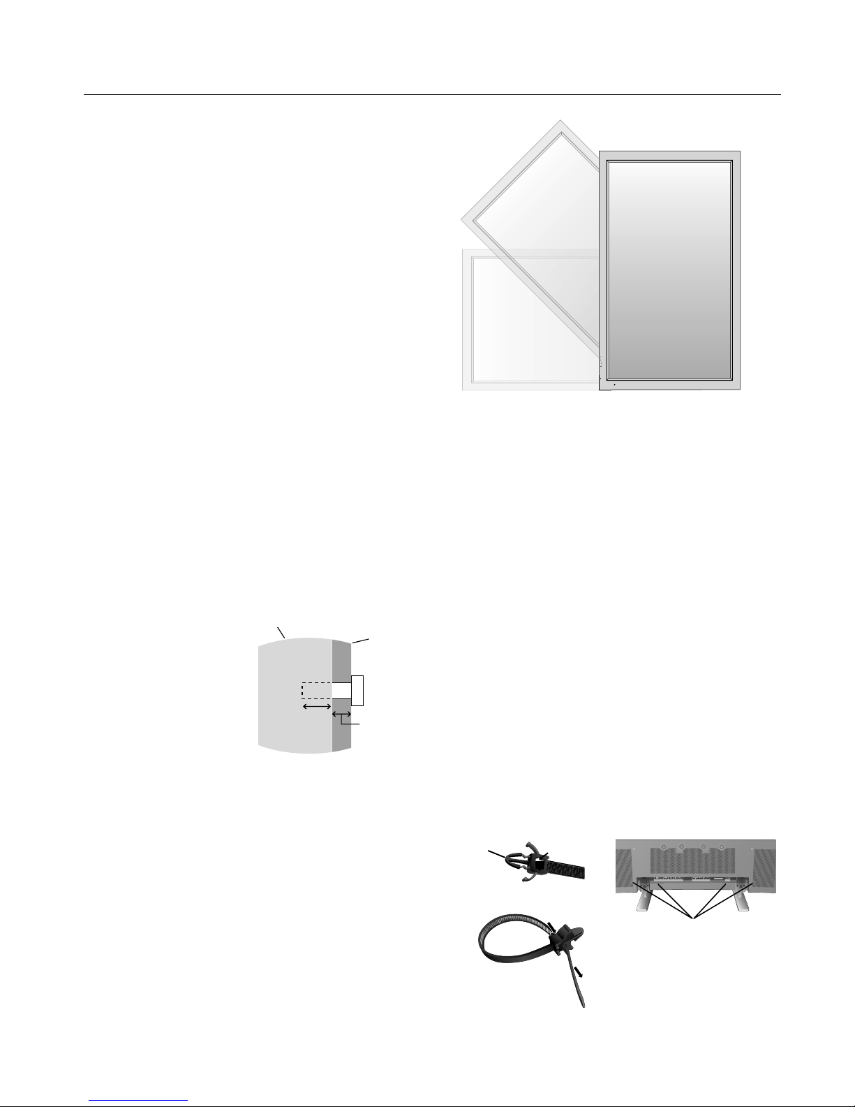
Orientation
When using the display in the portrait position, the monitor
should be rotated clockwise so that the le side is moved to
the top and the LED indicator light is on the bottom. is
will allow for proper ventilation and will extend the lifetime
of the monitor. Improper ventilation may shorten the
lifetime of the monitor.
When using the display in the portrait position, please turn
the Cooling Fan "ON" in the OPTION2 OSD menu.
•
•
•
•
•
•
•
MUTE
INPUT
EXIT MUTEINPUT
Cable Management
To conveniently manage cables, use the cable clamps
provided to bundle the power cord together with the signal
and audio cables at the back of the display.
To attach cable clamps:
1. Attach the cable clamps to the display. Insert the anchor of
the clamp into the hole on the back of the display. ere are 4
cable clamps and 4 clamp holes on the unit.
2. A er the cable clamp is positioned on the display, wrap the
end around the cables. Place the end of the clamp into the
slot near the anchor. Pull until cables are snug.
Clamps are designed to stay in place. Once in position, they
will be di cult to remove.
3. Cables can be routed to the right or le of the clamp. Use
the beaded bands to secure the cables together along their
length. Make sure the cables are fully supported.
To detach clamps:
Using pliers, twist the clamp 90 degrees and pull outward.
It is possible that the clamp can weaken over time and
removing it may cause damage to the clamp.
Installation - continued
Holes for Clamp
anchors
16mm
Anchor
Slot
Closed Clamp
Screw length should equal
depth of hole (16mm) + the
thickness of mounting bracket.
Unit
Mounting
Bracket
Screw
Thickness
of Bracket
Page 11
English
English-8
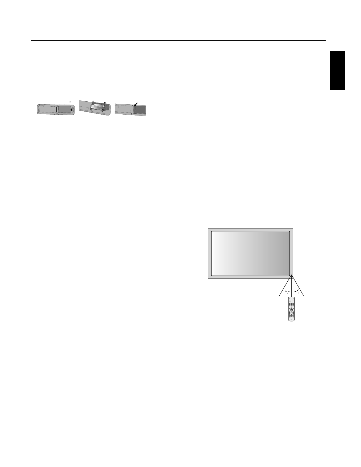
Using the Remote:
Install the remote control batteries.
e remote control is powered by AA batteries. To install or
replace batteries:
A. Press and slide to open the cover.
B. Align the batteries according to the (+)
and (–) indications inside the case.
C. Replace the cover.
CAUTION: Incorrect usage of batteries can result in leaks or
bursting. NEC recommends the following battery use:
Place “AA” size batteries matching the (+) and (-) signs
on each battery to the (+) and (-) signs of the battery
compartment.
Do not mix battery brands.
Do not combine new and old batteries, or mix brands.
is can shorten battery life or cause liquid leakage of
batteries.
Remove dead batteries immediately to prevent battery
acid from leaking into the battery compartment.
Do not touch exposed battery acid, it may injure skin.
Do not drop or mishandle the remote.
Do not get the remote control wet. If the remote does get
wet, wipe dry immediately.
Avoid excessive heat and humidity.
Do not dispose of batteries in re.
Please follow government regulations or public
environmental rules that apply in your country/area
when disposing of used batteries.
When replacing, use only conventional nonrechargeable alkaline or manganese batteries.
ere is a risk of explosion if batteries are replaced
incorrectly.
•
•
•
•
•
•
•
•
•
•
•
•
Operating Range for the Remote Control
Point the top of the remote control toward the monitor’s
remote sensor while pressing buttons. e remote control
can be used from the front of the monitor at a maximum
distance of 7 m/23 . from the front of the Plasma monitor’s
remote control sensor. e maximum horizontal and vertical
angle for use of the remote is 30 degree within a distance of
3.5 m/11.5 .
CAUTION
e remote control may not function when direct sunlight
or strong illumination strikes the remote control sensor of
the Plasma monitor, or when there is an object in the path of
the sensor.
Handling the Remote Control
Do not open the remote control other than to install
batteries. Do not allow water or other liquid to splash onto
the remote control. If the remote control gets wet, wipe it dry
immediately.
Avoid exposure to heat and steam.
NOTE: If you do not intend to use the Remote Control for a
long period of time, remove the batteries.
Installation - continued
EXIT MUTEINPUT
30
30
PICTURE
MEMORY
POWER ON
RGB DVD/HD VIDEO
PICTURE
MODE
DISPLAY
AUTO
SET UP
VOL
SPLIT SCREEN
REMOTEID
SWAP
SET RESET
REMOTE CONTROLLER RU-M113
SLEEP
SELECT/FREEZE
CAPTURE
PIP
S BY S SINGLE
MUTE
ZOOM
POINTER
EXIT
MENU
SIZE
STANDBY
123
456
7809
SET
+
++
Page 12
English-9
Part Names and Functions
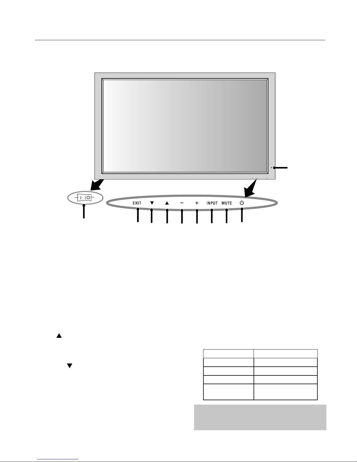
Control Panel
1) POWER
Switches the power on/standby.
2) MUTE
Switches the audio mute ON/OFF.
3) INPUT
Switches between input sources.
Acts as SET button within the OSD menu.
4) PLUS (+)
Increases the setting adjustment within OSD menu.
5) MINUS (-)
Decreases the setting adjustment within OSD menu.
6) UP ( )
Increases the volume level when the OSD is o .
Moves area up to select which setting to is to be adjusted
within OSD menu.
7) DOWN ( )
Decreases the volume level when the OSD is o .
Moves down to select which setting is to be adjusted within
OSD menu.
8) EXIT
Activates the OSD menu when the OSD menu is o .
Exits from the current menu being displayed to the
previous menu within the OSD.
9) Remote control sensor and Power indicator
Receives the signal when using the wireless remote control.
Glows green when the monitor is active. Glows red when
the monitor is in Standby mode. Glows Amber when the
monitor is in POWER SAVE mode.
A red blinking Power indicator means that the monitor has
detected a failure. Contact quali ed personnel in case of
failure.
10) Main Power Switch
Seesaw switch to turn the main power on/o .
Mode Status indicator light
Power On Green
Standby Red
Power save Amber
Diagnosis
(Detecting failure)
Red blinking
EXIT MUTEINPUT
1
9
2
3
45
6
7
8
OFFON
10
NOTE:
The POWER button does not completely turn off the
display. Use the Main Power Switch to completely turn off
the display.
Page 13
English
English-10
EXTERNAL CONTROL
OUT
2
IN
S-VIDEO IN
DVI AUDIO3
R
L
(MONO)
R
L
(MONO)
R
L
(MONO)
AUDIO2 AUDIO1VGA
HD VD
R/Cr/Pr G/Y B/Cb/pb
RGBHV / DVD/HD2
Y Cr/Pr Cb/Pb
DVD/HD1
IN
IN/OUT
VIDEO AC IN
RL
SPEAKER (S)
1
3 4 5 6 7 8 9
12
1110
13 14
Part Names and Functions
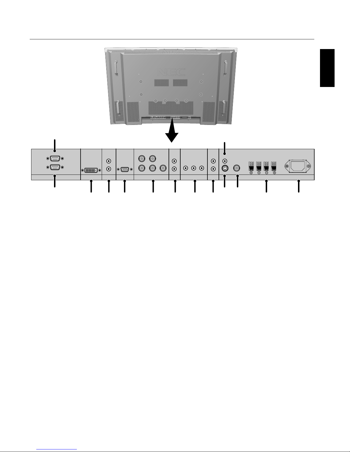
1) EXTERNAL CONTROL OUT (D-Sub 9 pin)
Connect RS-232C output to a second monitor.
2) EXTERNAL CONTROL (D-Sub 9 pin)
Connect RS-232C input to external equipment such as a
PC in order to control RS-232C functions.
3) DVI
Input digital RGB signals from a computer or HDTV
device having a digital RGB output.
4) AUDIO3
Input the audio signal from external equipment such as a
computer, VCR or DVD player.
5) VGA (Mini D-Sub 15 pin)
Analog computer input or output.
For proper operation select "D-SUB INPUT" in the
OPTION1 OSD menu.
6) RGBHV/DVD/HD2
RGBHV: Input RGB signals from RGB equipment.
A Sync-on-Green signal can be connected using the
G connector.
DVD/HD2: Connect equipment such as a DVD player,
HDTV device, or set-top box.
is input can be used with an RGB or component source.
For proper operation select "BNC INPUT" in the
OPTION1 OSD menu.
7) AUDIO2
Input the audio signal from external equipment such as a
computer, VCR or DVD player.
8) DVD/HD1
Connect equipment such as a DVD player, HDTV device,
or set-top box.
9) AUDIO1
Input the audio signal from external equipment such as a
computer, VCR or DVD player.
10) S-VIDEO in
Input S-video.
11) VIDEO1
Composite video input or output.
12) VIDEO2
Composite video input.
13) EXTERNAL SPEAKER (L and R) connector
Connects to optional speakers. Output the audio signal
from AUDIO 1, 2, and 3 to external speakers.
NOTE: Speaker Terminal is for 8W + 8W (8 ohm).
14) AC IN
Connects with the supplied power cord.
Information:
For Y/Cb/Cr connections, use the DVD/HD1 or DVD/HD2
terminals.
For SCART connections there are 3 ways to connect:
SCART1: Connect R/G/B to the DVD/HD2 terminals and
composite sync. to the HD terminal.
SCART2: Connect R/G/B to the DVD/HD2 terminals and
composite sync. to the VIDEO1 terminal.
SCART3: Connect R/G/B + composite sync. to the VGA
terminal.
Terminal Panel
Page 14
English-11
Part Names and Functions - continued
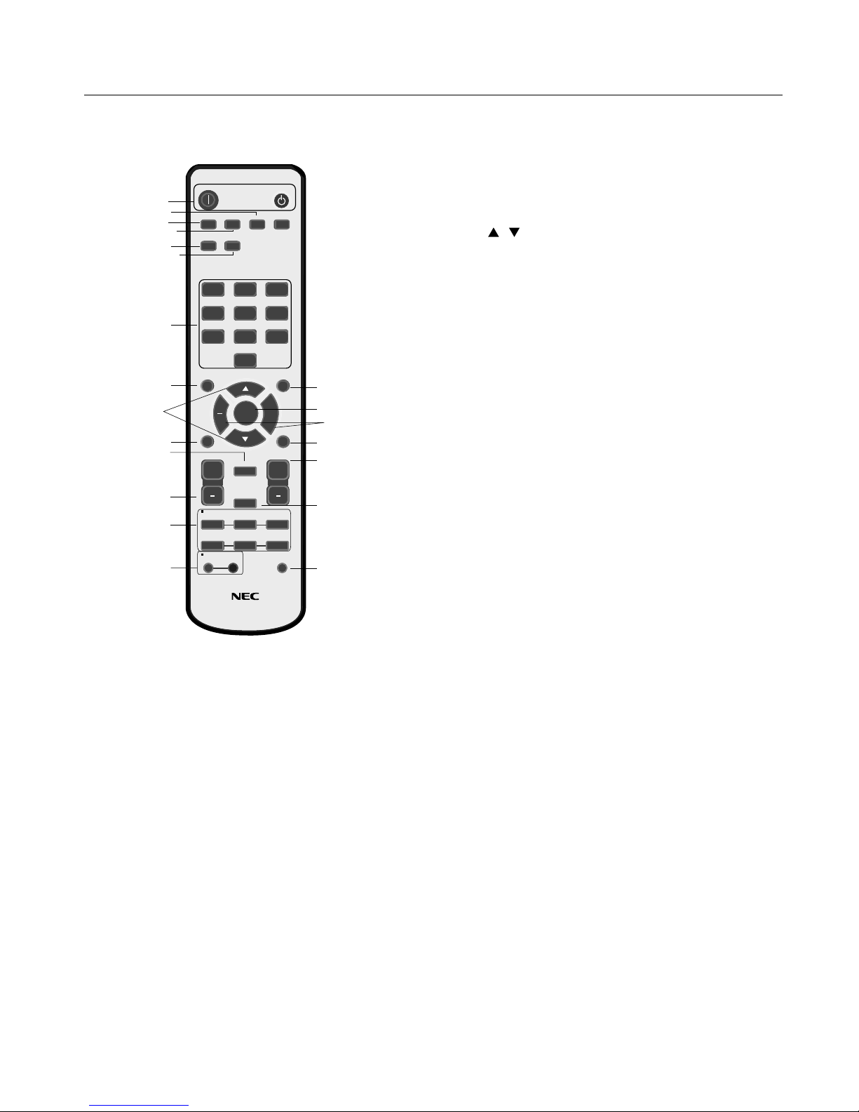
1) POWER ON/STANDBY
Switches the power on/standby.
*If the Power Indicator on the display is not glowing,
then no controls will work.
2) VIDEO
Switches the input signal to the VIDEO source.
3) RGB
Switches the input signal to the RGB source.
4) DVD/HD
Switches the input signal to the DVD/HD source.
5) PICTURE MODE
Selects Picture Mode: [STANDARD], [BRIGHT],
[CINEMA1], [CINEMA2], [DEFAULT].
STANDARD: for viewing in a bright room
BRIGHT: brighter picture than STANDARD
CINEMA1, 2: for viewing in a dark room, good for
movies
DEFAULT: factory default settings
6) SIZE
Set the aspect ratio of the image.
7) KEYPAD
Set REMOTE ID.
8) DISPLAY
Turn on/o the Information OSD.
9)
Move selection up or down
10) AUTO SETUP
Adjusts the CLOCK PHASE, CLOCK, and POSITION
settings automatically. (Analog RGB signal input only)
11) POINTER
Turn on/o the pointer.
12) VOLUME
Increases/Decreases sound level.
13) SPLIT SCREEN
PIP: Picture-in-Picture mode.
S BY S: Side-by-side mode.
SINGLE: Returns to normal mode.
SWAP: Swaps the Split Screen images.
When the QUICK SWAP function (see OSD OPTION4)
is ON, SWAP can be used to change signal input. (Single
screen mode)
SELECT/FREEZE: Selects which input is active when
in split screen mode.
When the PIC FREEZE function (see OSD Option4) is
operating, SELECT/FREEZE can be used to display still
pictures on the sub screen.
CAPTURE : Captures still picture.
14) REMOTE ID
Activates REMOTE ID function.
15) MENU
Turns ON/OFF menu mode.
16) SET
Makes selection.
17) - , +
Increases or decreases amount of adjustment.
18) EXIT
Goes to the previous menu.
19) ZOOM
Enlarges or reduces the picture.
20) MUTE
Mutes audio output.
21) SLEEP
Sleep timer.
NOTE: Any buttons without a corresponding explanation
will not work with the Plasmasync display.
PICTURE
MEMORY
POWER ON
RGB DVD/HD VIDEO
PICTURE
MODE
DISPLAY
AUTO
SET UP
VOL
SPLIT SCREEN
REMOTEID
SWAP
SET RESET
REMOTE CONTROLLER RU-M113
SLEEP
SELECT/FREEZE
CAPTURE
PIP
S BY S SINGLE
MUTE
ZOOM
POINTER
EXIT
MENU
SIZE
STANDBY
123
456
7809
SET
+
+
+
1
2
3
4
5
6
8
9
7
10
13
11
14
15
16
18
20
19
21
17
12
Remote Control Functions
Page 15
English
English-12
POWER
To turn the unit ON and OFF:
1. Plug the power cord into an AC outlet.
2. Press the Power button (on the unit).
e monitor's ON/STANDBY indicator turns red and the
unit will be in STANDBY mode.
3. Press the POWER ON button on the remote control. e
ON/STANDBY indicator will turn green when the unit is
active.
4. Press the STANDBY button (on the remote) or the Power
button (on the unit) to turn o the monitor.
DISPLAY
To check display settings press the DISPLAY button on the
remote. e screen changes each time the DISPLAY button is
pressed. Display information will disappear a er 3 seconds.
DIGITAL ZOOM
Digital zoom can change the picture position or enlarge the
image on the screen.
1. Be sure ZOOM NAV function is o . Press the ZOOM
button (+ or -) to display the magnifying glass.
Press the ZOOM + button to enlarge the image.
Press the ZOOM - button to reduce the image.
Press the UP and DOWN or PLUS and MINUS buttons to
reposition the picture.
2. Press the POINTER button to hide the pointer.
POINTER
Use the Pointer to point to a speci c area on the screen.
Press the UP and DOWN or PLUS and MINUS buttons to
reposition the Pointer.
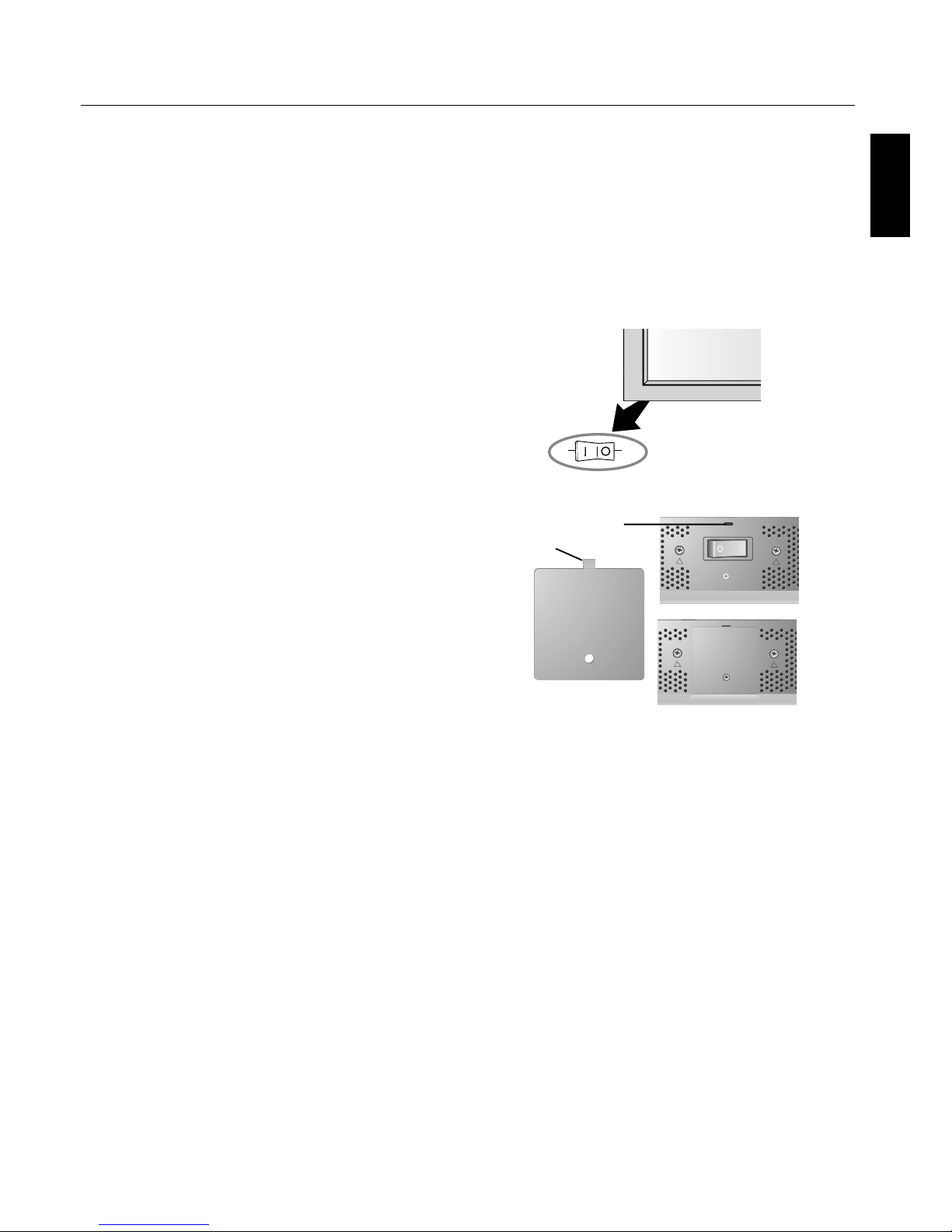
Main Power Switch Cover
Included with the display is a cover for the Main Power
Switch. Use this cover to prevent the unit from being
inadvertently powered o .
Place the tab on the cable cover into the rectangular slot on
the display.
en using the screw provided, secure the cover to the
display.
Part Names and Functions - continued
TAB
SLOT
OFFON
Main Power
Switch
Cover
Page 16
English-13
REMOTE CONTROL ID
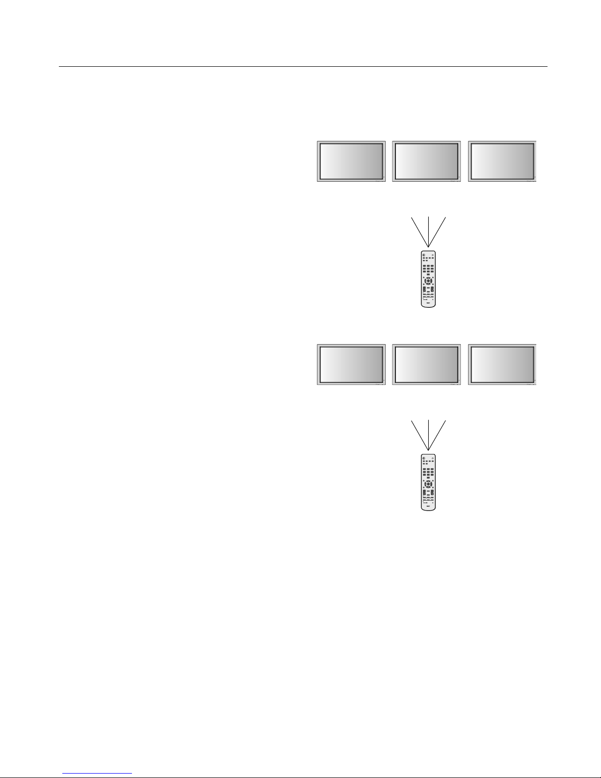
e remote control included with the display can be used
to control up to 26 individual monitors using what is
called the REMOTE CONTROL ID mode. e REMOTE
CONTROL ID mode works in conjunction with the Monitor
ID, allowing control of up to 26 individual monitors. For
example: if there are many monitors being used in the same
area, a remote control in normal mode would send signals to
every monitor at the same time Figure 1. Using the remote
in REMOTE CONTROL ID mode will only operate one
speci c monitor within the group Figure 2.
TO SET REMOTE CONTROL ID:
While holding down the REMOTE ID SET button on the
remote control, use the KEYPAD to input the Monitor ID
(1-26) of the display to be controlled via remote. e remote
can then be used to operate the monitor having that speci c
Monitor ID number.
When 0 is selected or when the remote control is in normal
mode, all monitors will be operated.
TO USE REMOTE CONTROL ID MODE
ID Mode - To enter ID Mode press the REMOTE ID SET
button and hold down for 2 seconds.
Normal Mode - To return to Normal Mode press the
REMOTE ID RESET button and hold down for 2 seconds.
In order for this feature to work properly, the display must
be assigned a Monitor ID number. e Monitor ID number
can be assigned under the OPTION3 menu in the OSD (See
page 17).
If monitor ID is set to “ALL” , monitor is controled by remote
control not depend on remote ID.
EXIT MUTEINPUT EXIT MUTEINPUT EXIT MUTEINPUT
PICTURE
MEMORY
POWER ON
RGB DVD/HD VIDEO
PICTURE
MODE
DISPLAY
AUTO
SET UP
VOL
SPLIT SCREEN
REMOTEID
SWAP
SET RESET
REMOTE CONTROLLER RU-M113
SLEEP
SELECT/FREEZE
CAPTURE
PIP
S BY S SINGLE
MUTE
ZOOM
POINTER
EXIT
MENU
SIZE
STANDBY
123
456
7809
SET
+
++
EXIT MUTEINPUT EXIT MUTEINPUT EXIT MUTEINPUT
PICTURE
MEMORY
POWER ON
RGB DVD/HD VIDEO
PICTURE
MODE
DISPLAY
AUTO
SET UP
VOL
SPLIT SCREEN
REMOTEID
SWAP
SET RESET
REMOTE CONTROLLER RU-M113
SLEEP
SELECT/FREEZE
CAPTURE
PIP
S BY S SINGLE
MUTE
ZOOM
POINTER
EXIT
MENU
SIZE
STANDBY
123
456
7809
SET
+
++
Monitor ID:1 Monitor ID:2
Remote does
not work
Remote does
not work
Figure 2
Remote set up to
use Remote ID:3
Monitor ID:1 Monitor ID:2
Remote works Remote works
Figure 1
Remote in Normal
mode or the REMOTE
ID is set to 0
Remote Control ID Function
Part Names and Functions - continued
Monitor ID:3
Remote works
Monitor ID:3
Remote works
Page 17
English
English-14
On-Screen Display (OSD)
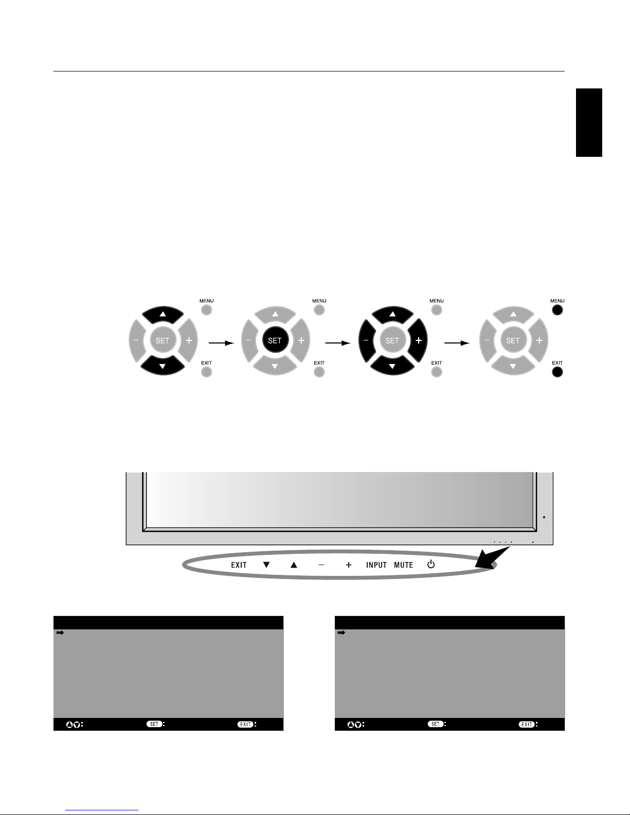
Using the OSD
Use the Remote Control or the control panel on the front
of the unit to enter the on-screen display menu to adjust
settings.
1. Press the MENU button on the remote or the EXIT button
on the Control Panel.
2. Use the up and down buttons to select the desired menu.
3. Press the SET button to select a sub-menu or item for
adjustment.
4. Change the setting or adjustment by pressing the + and
- buttons on the Control Panel or the Remote Control.
5. Press the EXIT button on the Remote Control, on the
Control Panel to return to the previous menu.
NOTE: Not all menu functions may be available. To access
all functions the Advanced OSD option must be turned on
in the ADVANCED OSD menu.
PICTURE
AUDIO
SCREEN
OPTION1
ADVANCED OSD OFF
NEXT PAGE
SEL. ENTER
MAIN MENU
1/2
EXIT
Press UP or DOWN
button to select
sub-menu.
Press SET. Press UP, DOWN, PLUS,
or MINUS to select the
function or setting to be
adjusted.
Press MENU or EXIT.
Press UP or DOWN
button to select.
Press INPUT
button to decide.
Press UP, DOWN, PLUS,
or MINUS to select.
Press EXIT.
Remote
Control
Control
Panel
OSD
Screen
EXIT MUTEINPUT
PICTURE
AUDIO
SCREEN
OPTION1
OPTION2
OPTION3
OPTION4
ADVANCED OSD ON
NEXT PAGE
SEL. ENTER
MAIN MENU 1/2
EXIT
ADVANCED OSD is OFF. Not all OSD functions will be
available when the ADVANCED OSD is off.
Advanced OSD is ON. All OSD functions are shown, but
some OSD functions may not be available.
Page 18
English-15
On-Screen Display (OSD)
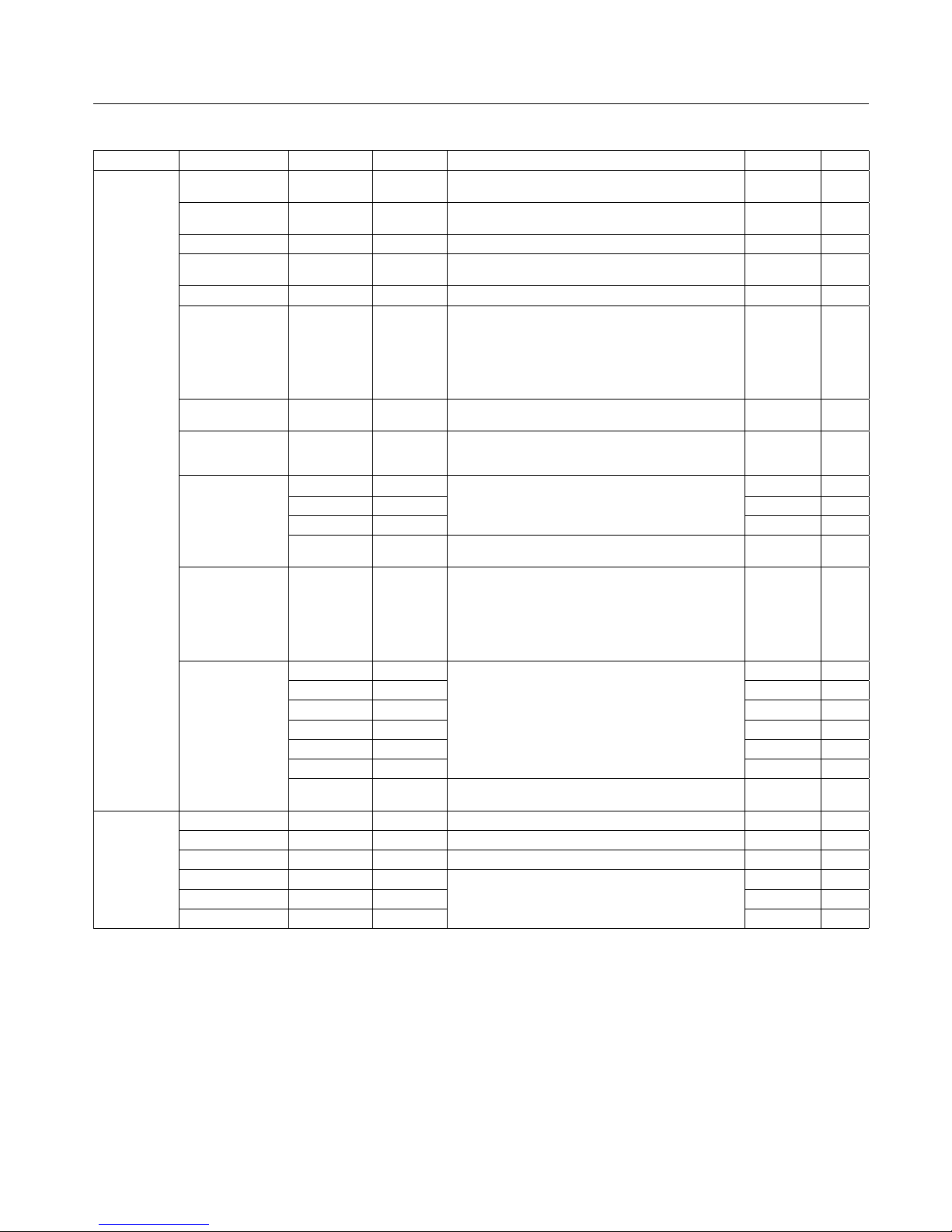
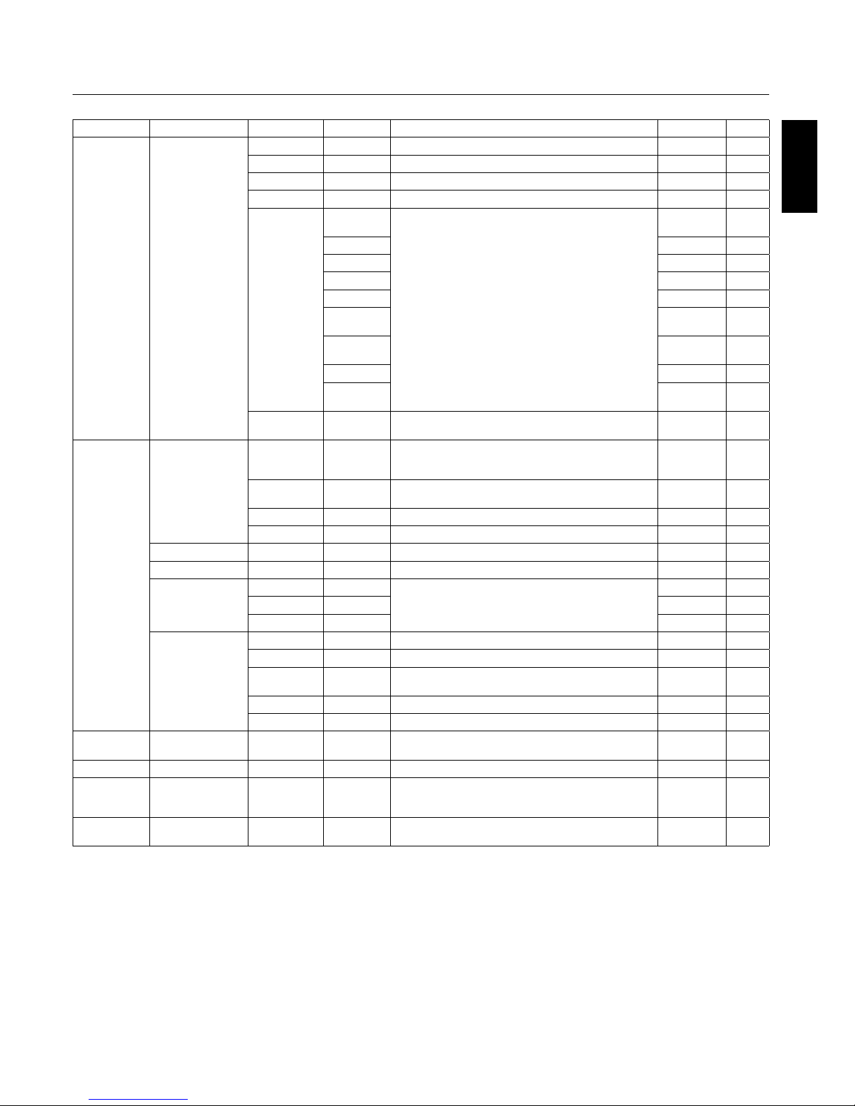
Main Menu Sub Menu Sub Menu2 Sub Menu3 Explanation Default Reset
PICTURE CONTRAST Adjusts the image brightness in relationship to the white
level. Pre ss + or - to adjust.
50 YES
BRIGHTNESS Adjusts the image brightness in relationship to the
background. Pr ess + or - to a djust .
50 YES
SHARPNESS Adjust s the crispness of the image. Pr ess + or - to a djust . 50 YES
COLOR Adjust s the color depth of the screen. Press + or - to
adjust.
50 YES
TINT Adjust s the tint of the screen. Press + or - to adjust. 50 YES
PICTURE MODE Selec ts picture mode, [BRIGHT ], [STANDARD] ,
[CINEMA1], [CINEMA2], [DEFAULT].
STANDARD: For watching in a bright room.
CINEMA1, 2: For watching in a dar k room, especially
good for m ovies.
BRIGHT: Brighter picture t han STANDARD.
DEFAULT: Resto res factor y default settings.
STANDARD YES
NR Adjust s the amo unt of noise reductio n. Pres s + or - to
adjust.
OFF YES
COLOR TEM P. Adjust s the color temperature of the entire s creen. A low
color temperature will make the screen reddish. A high
color temperature will make the screen bluish.
MID YES
WHITE BA LAN CE
Available only when
the Advanced OSD
function is enabled.
GAIN RED The "WHITE BAL ANCE" appears when the SE T button is
pressed on the "COLOR TEMP." OSD menu.
GAIN RED/GREEN /BLUE: Adjusts the white level of the
white balance.
50 YES
GAIN GREEN 50 YES
GAIN BLUE 50 YES
RESET Resets the factory default settings. Select "ON", then
press t he SET button to reset .
OFF YES
GAMMA
Available only when
the Advanced OSD
function is enabled.
Selec t a displ ay gamma for best picture qual ity.
2.1, 2.2, 2.3, 2.4: The picture become s darker as the
number increases.
S: Special gamma for certain types of movies. Raises
the dark parts and lowe rs the light parts of the image.
(S-Curve)
These va lues are approximate.
2.2 YES
COLOR CONTROL
Available only when
the Advanced OSD
function is enabled.
RED Adjust s the levels of the Red, Green, Blue, Yellow,
Magenta and Cyan.
VIDEO and DVD/ HD input only.
50 YES
GREEN 50 YES
BLUE 50 YES
YELLOW 50 YES
MAGENTA 50 YES
CYAN 50 YES
RESET Resets the factory default settings. Select "ON", then
press t he SET button to reset .
OFF YES
AUDIO BASS Adjust s the low freque ncy sound. Press + or - to adj ust. 0 YES
TREBLE Adjust s the hig h frequency sound. Pr ess + or - to adjust . 0 YES
BALA NCE Adjust s the bal ance of L /R volume. Pr ess + or - to adjust . 0 YES
AUDIO INPUT1 Se lect which audio inpu t to use with the video source. VID EO1 YES
AUDIO INPUT2 DVD/HD1 YES
AUDIO INPUT3 VGA YES
Page 19
English
English-16
On-Screen Display (OSD)
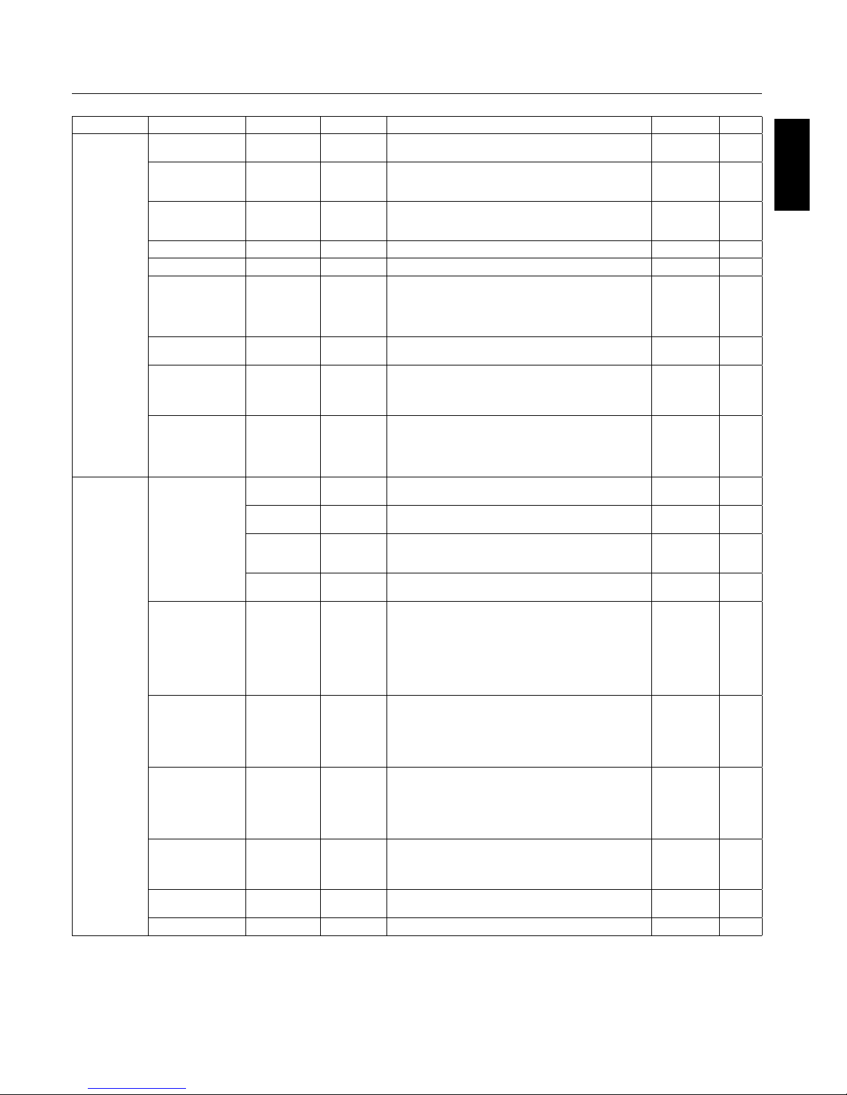
Main Menu Sub Menu Sub Menu2 Sub Menu3 Explanation Default Reset
SCREEN AS PECT MOD E Selects aspect ratio of the displayed image. Press + or
- to selec t.
V-POSITION Controls the vertical posi tion of the image within the
Display area of the PDP.
Press + to move up. Press - to move down.
0YES
H-POSITION Controls the horizontal position of the image within the
Display area of the PDP.
Press + to move right. Press - to move lef t.
0YES
V-HEIG HT Adjusts the vertical s ize of the image. 0 YES
H-WIDTH Adjust s the hor izont al size of the imag e. 0 YES
AUTO PICTU RE ON: H-Position, V-Position, Clock an d Clock Phase are
adjusted automatically.
OFF: H-Position, V-Position, Clock and Clock Phase are
adjusted manually.
VGA and RGBHV input only.
OFF NO
CLOCK PHASE Adjusts the visual “noise” on the image.
VGA and RGBHV input only.
0YES
CLOCK Pre ss + to expand the width of the image on the right of
the screen.
Press - to narrow the widt h of the image on the left.
VGA and RGBHV input only.
0YES
UNDER SCAN
Available only when
the Advanced OSD
function is enabled.
ON: UNDERSCAN is selec table in the ASPECT MODE
menu.
OFF: UNDERSCAN item is not selecta ble in the ASPECT
MODE menu.
Video signal input only.
OFF YES
OPTION1 OSD DISPLAY OSD ON: Information about inputs, screen size, etc. is shown.
OFF: No information is shown.
ON YES
OSD
POSITION
Change the position of t he menu b etween 1 and 6. Press
+ or - to adjust.
1YES
OSD ORBITER ON: The menu position intermittently shifts eight dots
while the OSD is being disp layed.
OFF: The menu p osition does not shif t.
OFF YES
OSD TRANSP. Adjust s the transparency level of the OSD.
Press + or - to adjus t.
70% YES
BNC INPU T Sel ects the input type when using 5BNC c onnectors .
RGB: For RGB input.
COMP.: For Component input ( 3BNC connector s) .
SCART1: For SCART input ( 4BNC co nnectors ).
SCART2 : For SCART input (3BNC con necto rs and V IDEO1
input).
SCART1, SCART2 available for Europe and World-Wide
models only.
RGB YES
D-SUB INPUT Selects the input type when using a mini D-SUB
connector.
RGB: For RGB input.
SCART3 : for SCART inp ut.
SCART3 available for Europe and World-Wide models
only.
RGB YES
RGB SELECT If there is a problem with signa l detec tion, this function
forces the monitor to dis play the signal at the desired
resolution.
If no problem is detecte d, the only available option will be
“AUT O”.
VGA and RGBHV input only.
AUTO YES
HD SELECT Manually s elects signal output when s imila r 1080I signal
are detected.
1080B: Standard digital broadcasts.
1080A: Special digital b roadc asts ( ex. DTC100 ).
108 0B NO
INPUT SK IP Skips to next input if present input signal i s not dete cted.
This function is valid only for INPUT key on the display.
OFF YES
ALL RESET Resets setti ngs bac k to factory default values. OFF
Page 20
English-17
On-Screen Display (OSD)
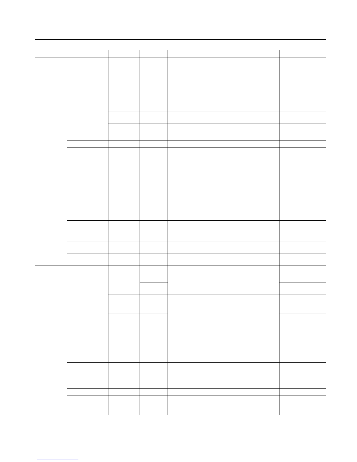
Main Menu Sub Menu Sub Menu2 Sub Menu3 Explanation Default Reset
OPTION2
Available only
when the
Advanced OSD
function is
enabled.
POWER SAVE Sets how long the monitor waits before going into power
save mode after a signal is lost.
VGA, RGBHV, and DVI input and Separate HV Sync. only.
OFF YES
FILM MODE S elects Film mo de. ON Y ES
SCREEN SAVER Use SCREEN SAVER functions to reduce the risk of image
retention.
PLE PLE: The brightness is decreased in order of Lock mode.
(the hi gher nu mber is darker )
AUTO YES
ORBITER ORBITER: The scr een image moves and is slightly
squeezed or expanded.
AUTO1 YES
INVERSE
WORKING TIME
/WAITING TIME
INVERSE: The scr een image is displayed alternately
between positive image and negative image, or t he screen
image is displayed full white.
OFF YES
COOLIN G FAN Cooling fan re duces the temperature of the display. AUTO NO
SIDE MASK Adjus ts the co lor of the side mask when a 4 :3 image is
displayed.
Press + button, the bar will become lighter.
Press - button, the bar will become dar ker.
3YES
PICTURE SIZE When it is set to "OFF", TRUE of picture size a ppears only
RGB signals.
ON YES
DVI MODE PLUG/PLAY Choose the DVI mode base d on the input devi ce
connected via DVI connector and set the black level.
When a PC or similar equipment is connected, the PLUG/
PLAY setting should be "DV I-PC" and the B LACK LEVEL
setting should be "LOW".
When a DVD p layer or s imila r equip ment is c onnected,
PLUG/ PLAY set ting should be "DVI-HD" and t he BLACK
LEVEL setting should be "HIGH".
DVI-PC NO
BLACK LEVEL LOW NO
PROTOCOL SET Sets protocol setting for use with RS-232C connection.
OFF: When NEC protocol is used (normal).
ON: When special protocol is used.
Consult dealer for details of protocol.
OFF YES
CLOSED CAPTION
U.S. models only
Choose the clos ed caption setting . OFF YES
CAPTION CONT
U.S. models only
Chooses the brightness of the closed captions. NORMAL YES
OPTION3
Available only
when the
Advanced OSD
function is
enabled.
TIMER PRESENT
TIME
DAYLIGHT
SAVING
TIME
Sets the date, tim e, and daylight s aving region.
Day & time must be set in orde r for the “TIMER ” function
to operate.
OFF NO
DAY/HOUR/
MINUTE
NO
TIMER Create s a working schedule for t he monitor to use. S ee
page 24 for instr uctio ns.
OFF YES
INPUT DE TECT INPUT Sets the input mode and the sound volume when the
power is tur ned on.
LAST: Uses the input that was last selected when the
power was tu rned off.
MULTI to DVI: Fixed input mode.
AUTO: Automatically searches for the inpu t signa l.
PRIORITY: Sets which input ha s priority when using the
AUTO setting.
LAST YES
VOLUME LAST YES
CONTRO L LOCK This function comple tely locks out ac cess to a ll Control
Key functions. W hen thi s item is set to "ON", the front
panel is disab led as soon as th e on-screen menu goes off.
OFF YES
IR REMOTE When "OFF", prevents the monitor from being controlled
by wireless remote controller. The remote beco mes
ineffective disabled as soon as the o n-screen menu goes
off. To retur n to normal operation, pres s the “DISPL AY”
button on the re mote controller for 5 se conds.
ON YES
LOOP OUT Change the loop out setting. OFF YES
MONITOR ID Sets the Monitor ID to a number from 1-26 and o r to ALL. ALL YES
RS232C CONTROL Selects the mode of the mo nitor when using the RS -232C
daisy chain.
NORMAL YES
Page 21
English
English-18
Main Menu Sub Menu Sub Menu2 Sub Menu3 Explanation Default Reset
OPTION3
(continued)
VIDEO WALL Sets the confi guration of video wall.
DIVIDER Sets the video wall. OFF YES
POSITION Sets the position of each display.
DISP. MODE Sets the mode of se am processing for each display. SPLIT YES
SCREEN ASPECT
MODE
Adjusts detail position.
V-POSITION 0YES
H-POSITION 0YES
V-HEIG HT 0YES
H-WIDTH 0YES
AUTO
PICTURE
OFF YES
CLOCK
PHASE
0YES
CLOCK 0YES
UNDER
SCAN
OFF YES
P.ON DELAY Adjust s the del ay time be tween being in “standby” mode
and entering “power on” mode.
OFF YES
OPTION4
Available only
when the
Advanced OSD
function is
enabled.
SUB PICTURE Automatically de tects i f there is an input signal for the sub
scree n. This feature is available only picture-in-picture
mode.
SUB P.
DETECT
Automatically detec ts sub screen. AUTO YES
DISPLAY Sets the appearance of the sub screen. NORMAL YES
SUB P. RATE Sets the tr ansparency of the sub screen. 100% YES
ZOOM NAV Sets the position of the zo om navigation image. BTM LFT YES
PIC FREEZE Sets the position of the captured still picture. S BY S1 YES
QUICK SWAP Enables quick swapping of input.
Sets which inpu t termi nals are used.
OFF YES
SELECT1 VIDEO1 YES
SELECT2 VGA YES
TEXT INSERT Allows text insertion within main screen. OFF YES
INPUT Sets the input of text image of the VGA, RGBHV, and DVI. VGA YES
SUB P.
DETECT
Automatically detec ts sub screen. AUTO YES
DISPLAY Sets the appearance of the sub screen. NORMAL YES
SUB P. RATE Sets the tr ansparency of the sub screen. 100% YES
ADVANCED
OSM
ON: All menu items are show n for adva nced users.
OFF: Some of the advanc ed menu items ar e not shown.
OFF YES
LANGUAGE Select the language used by the OSD. ENGLISH NO
COLOR
SYSTEM
The Color Syste m that is u sed depends on the video
format of the input sign al.
VIDEO input only.
AUTO NO
SOURCE
INFORMATION
Display information about the display: frequencies,
polarities, etc.
On-Screen Display (OSD)
Page 22
English-19
Operation
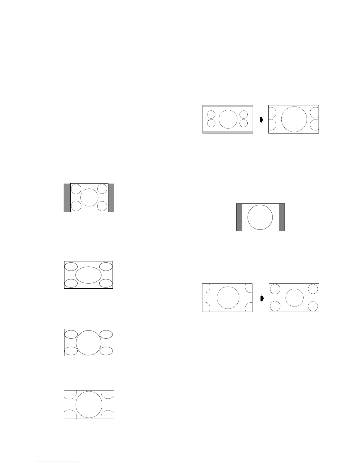
Picture Size Using Video Signals
Select one of seven picture sizes manually.
While viewing videos or digital video discs, perform the
following actions:
1. Press the SIZE button on the remote control.
2. To switch the screen sizes, press the SIZE button again
within 3 seconds. e available sizes are NORMAL, FULL,
DYNAMIC, ZOOM, 2.35:1, 14:9, and UNDERSCAN.
If a 720p, 1080i, or 1080p signal is displayed, the available
sizes are FULL, 2.35:1, DYNAMIC, and UNDERSCAN.
If displaying an enhanced split-screen, the available sizes are
NORMAL and FULL.
NORMAL (4:3)
Images with a 4:3 (Normal) aspect ratio are displayed.
FULL
Horizontally expands anamorphic signals to display the
correct linearity.
Normal (4:3) images are horizontally expanded to ll the
entire screen.
DYNAMIC
Vertically and horizontally expands the picture but at
di erent aspect ratios.
ZOOM
Vertically and horizontally expands the picture while
maintaining the correct aspect ratio.
2.35:1
Image is expanded at a 2.35:1 ratio to ll the entire screen.
e screen is lled vertically; however, some information
will be lost on the le and right sides of the image.
Available for the following inputs:
Video, Component, or RGB input (480I, 480P, 576I, 576P,
720P, 1080I, 1080P)
To avoid image retention, use the 2.35:1 image size if black
bars are displayed at the top and bottom of the screen
showing the displayed image.
14:9
Image is displayed at a 14:9 aspect ratio.
Available for the following inputs:
Video, Component, or RGB input (480I, 480P, 576I, 576P)
UNDERSCAN
Standard televisions crop (Underscan) images. Utilize the
UNDERSCAN function in the SCREEN menu to display the
entire image.
NOTE: Depending on the type of component used, black
borders or signal noise may appear near the screen
edges while in UNDERSCAN mode.
Over a period of time, image ghosting, shadowing,
or burn-in may result from continuous display of
underscanned images. While in UNDERSCAN
mode, the brightness may change if a Macrovision
signal is input.
NOTE: Do not display 4:3 content in NORMAL mode for
extended periods of time to avoid image ghosting,
shadowing, or burn-in.
Page 23
English
English-20
Operation - continued
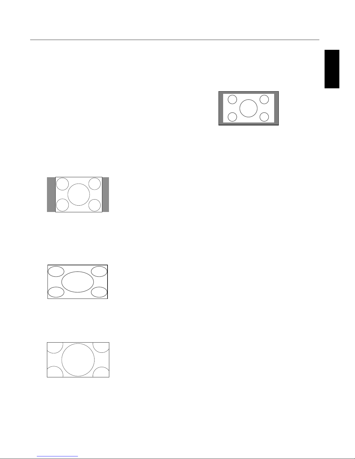
Picture Size Using Computer
Signals
To expand a 4:3 image to ll the entire screen, switch to the
widescreen mode.
While viewing videos or digital video discs, perform the
following actions:
1. Press the SIZE button on the remote control.
2. To switch the screen sizes, press the SIZE button again
within 3 seconds. e available sizes are NORMAL, FULL,
and ZOOM.
If an enhanced split-screen is displayed, the available sizes
are NORMAL and FULL.
NORMAL (4:3 or SXGA 5:4)
Images are displayed normally.
FULL
Horizontally expands anamorphic signals to display the
correct linearity.
Normal (4:3) images are horizontally expanded to ll the
entire screen.
ZOOM
Vertically and horizontally expands the picture, while
maintaining the correct aspect ratio.
TRUE
e image is displayed at the native resolution.
When using a VGA or SVGA signal, PICTURE SIZE in the
OPTION 2 OSD menu should be set to OFF to select TRUE
mode.
Information:
Supported resolutions: For further information on the
display output of the various VESA signal standards
supported by the unit, see pages 34 - 39.
When 1360 dot x 768 line wide XGA signals with a vertical
frequency of 60 Hz and a horizontal frequency of 47.7 kHz
are input:
1. Select an appropriate setting for the RGB SELECT mode.
2. Refer to the Resolutions Supported section of Model
Information on pages 34 - 39.
NOTE: Do not display 4:3 content in NORMAL and TRUE
mode for extended periods of time to avoid image
shadowing, ghosting, or burn-in.
Page 24
English-21
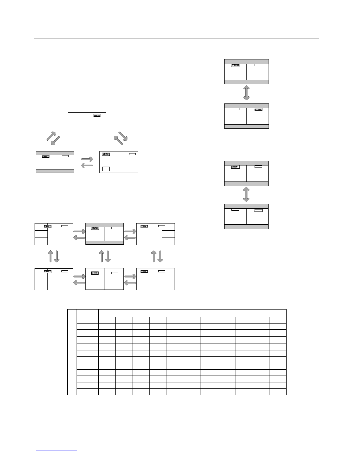
Split Screen Mode
To display multiple pictures on the screen, perform the
following actions:
1. Press the desired SPLIT SCREEN function button on the
remote (PIP, S BY S, SINGLE).
Only certain RGB signals are supported.
Split Screen mode works according to the table below.
Side by Side Mode
Press the -, +, p or q buttons to change the picture size.
Press the SWAP button to swap pictures.
Press the SELECT/FREEZE button to change the active
picture.
Operation - continued
Picture displayed on the Left / Sub screen
Picture displayed on the Right / Main screen
VIDEO1 VIDEO2 S-VIDEO DVD/HD1 DVD/HD2 SCART1 SCART2 SCART3 VGA RGBHV DVI
VIDEO1 — YES YES YES YES — — — YES YES YES
VIDEO2
YES — YES YES YES — — — YES YES YES
S-VIDEO
YES YES — YES YES — — — YES YES YES
DVD/HD1 YES YES YES — YES — — — YES YES YES
DVD/HD2 YES YES YES YES — — — — YES — YES
SCART1 — — — — — — — — — — YES
SCART2 — — — — — — — — — — YES
SCART3 — — — — — — — — — — YES
VGA YES YES YES YES YES — — — — — YES
RGBHV YES YES YES YES — — — — — — YES
DVI YES YES YES YES YES YES YES YES YES YES —
AB
VGA
BA
VGA
SWAP
AB
VGA
AB
VIDEO1
VGA
SELECT/FREEZE
VIDEO1 is active.
VGA is active.
S BY S
button
A
AB
VGA
A
VGA
B
S BY S
button
SINGLE
button
PIP
button
PIP
button
SINGLE
button
B
A
VGA
A
B
VGA
A
B
VGA
B
A
VGA
AB
VGA
A
B
VGA
Side by Side4-R Side by Side3 Side by Side4-L
q
button
p
button
q
button
p
button
q
button
p
button
+
button
-
button
Side by Side2-R Side by Side1 Side by Side2-L
+
button
-
button
+
button
-
button
+
button
-
button
Page 25
English
English-22
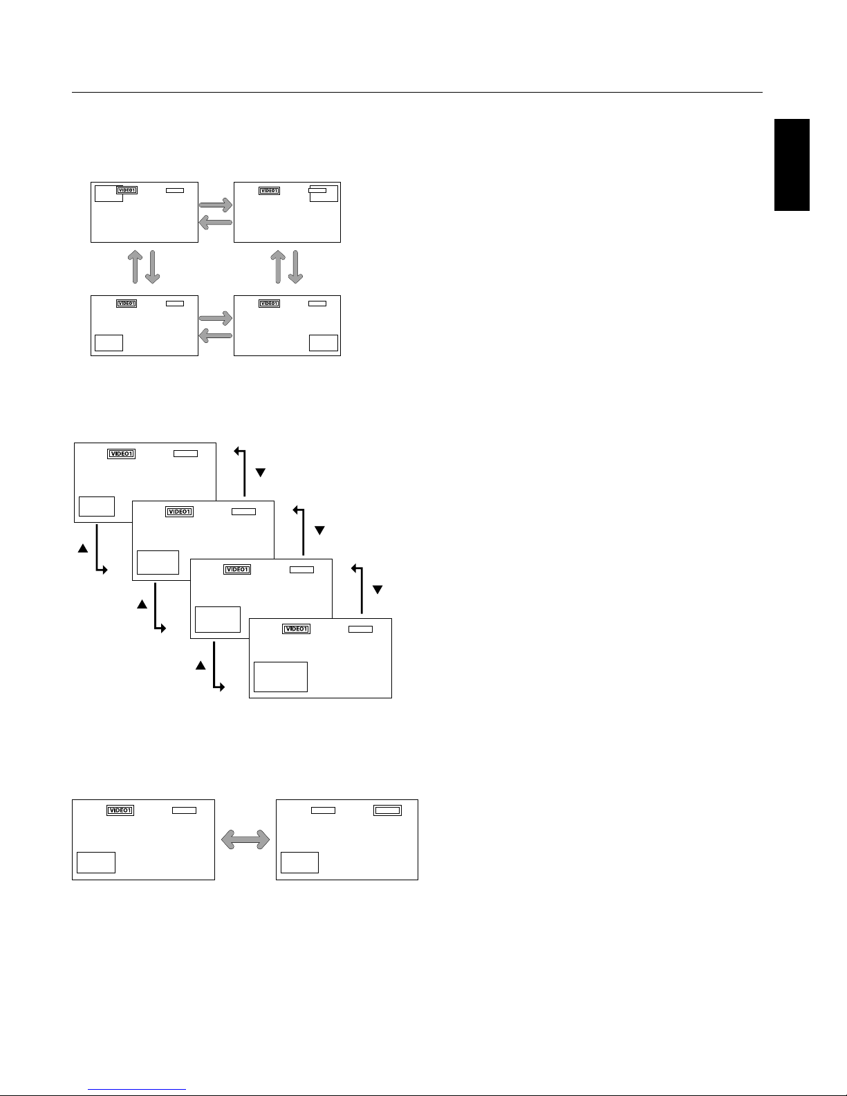
Picture-in-Picture Mode
Press the + and - buttons to change the position of the subpicture.
Press the p and q buttons to change the size of the subpicture.
Press the SELECT/FREEZE button to change the active
picture.
Displaying Input Signal
1. To make the desired picture active, press the SELECT/
FREEZE button.
2. To change the active signal, press the VIDEO, DVD/HD,
or RGB button.
e input selection may also be changed by pressing the
INPUT button on the front of the unit.
Adjusting the OSD controls
1. To make the desired picture active, press the SELECT/
FREEZE button.
2. To display the main menu, press the MENU button.
3. Adjust the settings as desired.
NOTE: Some OSD functions may not be available in Split-
Screen mode.
Operation - continued
A
VGA
A
VGA
A
B
B
VGA
A
VGA
B
B
-
button
+
button
+
button
-
button
+
button
-
button
-
button
+
button
A
B
VGA
A
B
VGA
A
B
VGA
A
B
VGA
button
button
button
button
button
button
A
B
VGA
A
B
VIDEO1
VGA
Page 26
English-23
Operation - continued
Creating a Video Wall
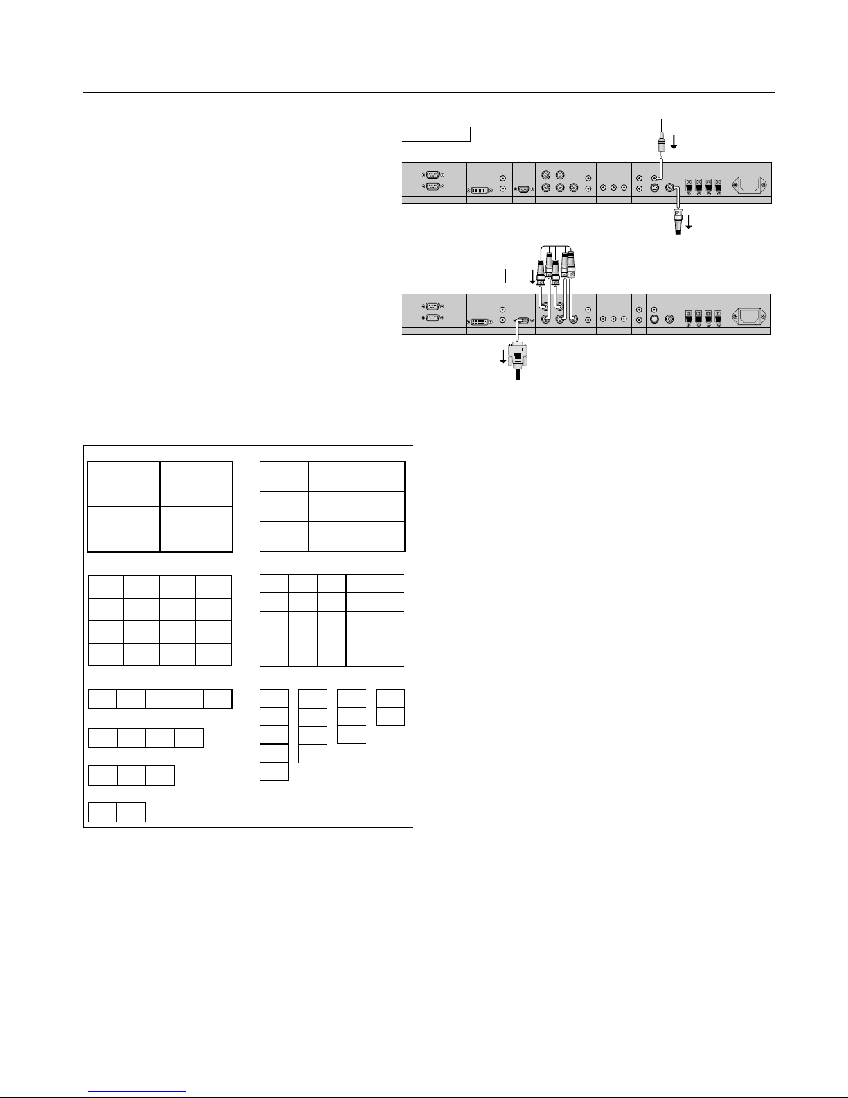
You can create a video wall consisting of up to 25 individual
monitors with the built-in matrix display capability. Your
Video Wall can have any of the following con gurations:
2x2, 3x3, 4x4, 5x5, 5x1, 4x1, 3x1, 2x1, 1x2, 1x3, 1x4, or 1x5.
Connect the signal cables as shown:
1. Select VIDEO WALL in the OPTION 3 OSD menu, then
press the SET button.
2. Select the desired video wall con guration in the
DIVIDER eld.
3. Select POSITION in the VIDEO WALL menu, then press
the SET button. Appearing on the OSD is the current video
wall con guration. Select the position of the monitor for the
video wall.
NOTE: Each individual monitor within the video wall must
have its own set position.
EXTERNAL CONTROL
OUT
IN
S-VIDEO IN
DVI AUDIO3
R
L
(MONO)
R
L
(MONO)
R
L
(MONO)
AUDIO2 AUDIO1VGA
HD VD
R/Cr/Pr G/Y B/Cb/pb
RGBHV / DVD/HD2
Y Cr/Pr Cb/Pb
DVD/HD1
IN
IN/OUT
VIDEO
AC IN
RL
SPEAKER (S)
Video Signal
RCA Phono Plug
(IN)
BNC connector
(OUT) to another
display
EXTERNAL CONTROL
OUT
IN
S-VIDEO IN
DVI AUDIO3
R
L
(MONO)
R
L
(MONO)
R
L
(MONO)
AUDIO2 AUDIO1VGA
HD VD
R/Cr/Pr G/Y B/Cb/pb
RGBHV / DVD/HD2
Y Cr/Pr Cb/Pb
DVD/HD1
IN
IN/OUT
VIDEO AC IN
RL
SPEAKER (S)
RGB/DVD/HD Signal
BNC connector
(IN)
VGA connector
(OUT) to
another
display
NO. 16 NO. 17 NO. 18 NO. 19
NO. 20 NO. 21 NO. 22 NO. 23
NO. 24 NO. 25 NO. 26 NO. 27
NO. 28 NO. 29 NO. 30 NO. 31
NO. 5NO. 4NO. 3NO. 1 NO. 2
NO. 32 NO. 33 NO. 34 NO. 35 NO. 36
NO. 37 NO. 38 NO. 39 NO. 40 NO. 41
NO. 42 NO. 43 NO. 44 NO. 45 NO. 46
NO. 47 NO. 48 NO. 49 NO. 50 NO. 51
NO. 52 NO. 53 NO. 54 NO. 55 NO. 56
NO. 7 NO. 8 NO. 9
NO. 10 NO. 11 NO. 12
NO. 13 NO. 14 NO. 15
NO. 1 NO. 2
NO. 4 NO. 3
2 x 2 3 x 3
4 x 4 5 x 5
5 x 1
NO. 4NO. 3
NO. 3
NO. 1 NO. 2
4 x 1
NO. 1
NO. 2
NO. 3
NO. 4
NO. 5
1 x 5
NO. 1
NO. 2
3 x 1
NO. 1 NO. 2
2 x 1
NO. 1
NO. 2
NO. 3
NO. 4
1 x 4
NO. 1
NO. 2
NO. 3
1 x 3
NO. 1
NO. 2
1 x 2
Video Wall Confi gurations
NOTE: 1. e VIDEO 1 and VGA terminals may be used
either for INPUT or OUTPUT.
Do not connect an OUTPUT signal from another
unit when LOOP OUT in the OPTION 3 OSD is set
to ON, as it may damage the other unit due to an
extraordinary load.
2. While signals are input to the VGA terminal,
LOOP OUT should not be turned ON.
Information:
Set the LOOP OUT in OPTION3 to ON to loop signals out
to another plasma display.
Set the VIDEO WALL options properly when creating a
video wall.
Use the appropriate (length and e ciency) BNC cable to
connect monitors.
If the image quality is poor, do not use the monitor out
terminal to link to another monitor. Use a commercially
available distribution ampli er to connect the split signal
to the appropriate monitor INPUT terminals.
For a resolution of 1024x768 at 60 Hz (or lower), the
maximum recommended size for a viewing wall is 4
displays.
A distribution ampli er is highly recommended when
setting up a 3 x 3 (or greater) video wall.
When looping from plasma to plasma, an appropriate
(length and e ciency) 15-pin male mini D-Sub - 5BNC
conversion cable is required.
•
•
•
•
•
•
Page 27

English
English-24
USING THE TIMER
Turn the “ADVANCED OSD” to “ON” in the MAIN MENU
to access the TIMER feature in OPTION3.
To user the TIMER feature the rst set the internal clock and
the day of the week. e display can also be programmed to
turn on or o at preset times, and which input the display
will use at those times. e Program Timer which turns on
or o the power at the day of the week, time and the input
mode you want, or Repeat Timer which displays two input
modes alternately can each be set also. In the “OPTION3”
OSD menu, select “TIMER”, then press the SET button. e
“TIMER” screen appears.
PRESENT TIME
is sets the day of the week and present time. Example:
Setting “WEDNESDAY”, “22:05” In the “TIMER” menu,
select “PRESENT TIME”, then press the SET button.
e “PRESENT TIME” screen appears. Set the items.
Turn DAYLIGHT SAVING TIME on if daylight
savings is observed.
Select the day of the week.
Set the clock using the 24-hour (HH/MM) format.
To accept PRESENT TIME settings, highlight “SET”* in the
PRESENT TIME OSD menu, then press the SET button to
store the settings.
* If you press the EXIT button instead of the SET button,
Timer settings will not be accepted.
PROGRAM TIMER
e PROGRAM TIMER feature allows a series of scheduled
operation times to be set. e display can be programmed to
run on a particular day and time while using a desired input
source. Under the Function setting (FUNC.) either a Screen
Saver setting (ORBITER, INVERSE, WHITE) or a REPEAT
TIMER program can be set for the monitor to use during the
scheduled power-on time.
NOTE: When a REPEAT TIMER program is selected as
the Function setting, the Program Timer's Input option
is not available. e input used will use the input that is
programmed for the Repeat Timer program.
Up to 10 individual PROGRAM TIMER schedules can be
set. When schedules are set to perform functions at the same
time, the schedule with the lower number has priority. For
example schedule #1 has priority over schedule #10. When
schedules overlap, each action is sequentially executed.
Using special characters in the PROGRAM TIMER
setting.
Using an asterisk (*) alone in the DAY eld means that the
programmed schedule will run every day.
Using the asterisk (*) and the name of the day means the
programmed schedule will run only on that day. For example
"*FRI" means that the schedule will run every Friday.
A hyphen (-) in either the ON or OFF elds means that a
time is not set. In order to use the Program Timer, at least
either an ON or OFF time has to be set.
A hyphen (-) in the INPUT or that the monitor will use the
previously used display mode for that particular schedule.
If a Repeat Timer sequence is selected in the FUNC. eld,
the Input eld will show a hyphen (-).
Setting the PROGRAM TIMER using multiple inputs
Set the INPUT eld to “MULTI”, then press the SET button.
e “MULTI SCREEN SETTING” will appear on the screen.
Use the p and q buttons to select “MULTI MODE”, then
use the + and - buttons to choose from “S BY S1, 2R, or
2L” and “PICTURE IN PICTURE MODE (BOTTOM
LEFT~TOP LEFT)”.
Use the p and q buttons to select “MAIN”/“SUB” and
“LEFT”/“RIGHT”, then use the + and - buttons to choose
from “VIDEO1 to "DVI”.
To set “REP.1~3” as the FUNC.
Set the FUNC. eld to “REP.1”, “REP.2” or “REP.3”, then press
the SET button. e “REPEAT TIMER” menu will appear on
the screen.
Use the - and + buttons to choose from “SINGLE”, “S BY S 1,
2R or 2L” and “PICTURE IN PICTURE MODE (BTM LFT
to TOP LFT)”, then adjust the items.
Operation - continued
Page 28

English-25
Operation - continued
REPEAT TIMER
e Repeat Timer allows the display to alternate between
inputs at user-determined intervals.
For example the display can be programmed to show the
signal from "VIDEO1" for 10 minutes and then switch to
showing the signal from the DVI input for 10 minutes.
To set the Repeat Timer select "REPEAT" in the Timer
menu, then press the SET button. To enter the REPEAT
TIMER OSD screen. en make the desired settings.
STATE Settings
ere are 4 possible state settings to use. When all four
STATES are set to "ON, the repeat timer schedules will
operate consecutively (State1, State2, State3, State4, State1,
State2, State3...).
When a STATE setting is set to OFF, i.e. STATE1-ON,
STATE2-ON, STATE3-OFF, STATE4-ON, the repeat timer
schedules use all but STATE3 (State1, State2, State4, State1,
State2...).
Repeat Timer activates when the OSD menu is exited.
For SINGLE display con gurations
WORK TIME: Set the time duration of the schedule. Time
range is from 1 minute to 24 hours.
INPUT MODE: Choose the signal that will be used.
MULTI settings
MODE: Select the input mode to be displayed as “SINGLE”,
“S BY S 1, 2R or 2L” or “PICTURE IN PICTURE MODE
(BTM LFT~TOP LFT)”.
WORK TIME: Set the time duration of the schedule. Time
range is from 1 minute to 24 hours.
INPUT MODE: Choose the signal that will be used.
Select “MAIN” or “SUB” for “PICTURE IN PICTURE
MODE (BTM LFT~TOP LFT)” and “LEFT” or “RIGHT” for
“S BY S1, 2R or 2L”.
Only one signal is selected for “SINGLE”.
Page 29
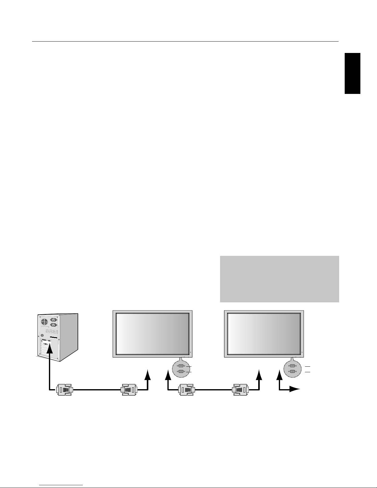
English
English-26
is monitor uses RXD, TXD and GND
lines for RS-232C control.
e reverse type cable (null modem cable)
should be used for RS-232C control.
is Plasma monitor can be controlled via personal
computer using an RS-232C connection.
MONITOR ID and RS-232C CONTROL
Up to 26 individual monitors can be controlled through a
daisy chain via RS-232C connection.
1. Connect PC to the monitor.
Connect a PC’s RS-232C control output to the monitor's
RS-232C input. You can then connect the
RS-232C output from this monitor to another monitor’s
RS-232C input. Up to 26 monitors can be connected
using RS-232C.
2. Set Monitor ID and RS-232C Control mode.
For proper operation, the Monitor ID should be set
in the OSD menu of each monitor that is in the chain.
e Monitor ID can be set under the “OPTION3”
menu in the OSD. e Monitor ID number can be set
within a range from 1 to 26 or set to "ALL". No two
monitors should share the same Monitor ID number.
It is recommended to number each monitor in a daisy
chain sequentially from 1. e rst monitor in the daisy
chain is designated as the primary monitor. Subsequent
monitors with the chain are secondary monitors.
In the “OPTION3” menu on the rst monitor in the
RS-232C daisy chain set the "RS232C CONTROL" to
"NORMAL". Set the "RS232C CONTROL" to “2ND”
on all other monitors.
Functions that can be controlled via RS-232C:
Powering ON or OFF
Switching input signals
NOTE: If your PC (IBM or IBM compatible) is equipped
only with a 25-pin serial port connector, a 25-pin
serial port adapter is required. Contact your dealer
for details.
NOTE: In order to function, the RS-232C OUT terminal
can only be connected to another monitor of the
same model. Do not connect to other types of
equipment.
•
•
RS-232C
EXIT MUTEINPUT EXIT MUTEINPUT
PC
(Out)
RS-232C Cable RS-232C Cable
RS-232C (IN)
RS-232C (OUT)
IN
OUT
IN
OUT
RS-232C (IN)
RS-232C (OUT)
Page 30
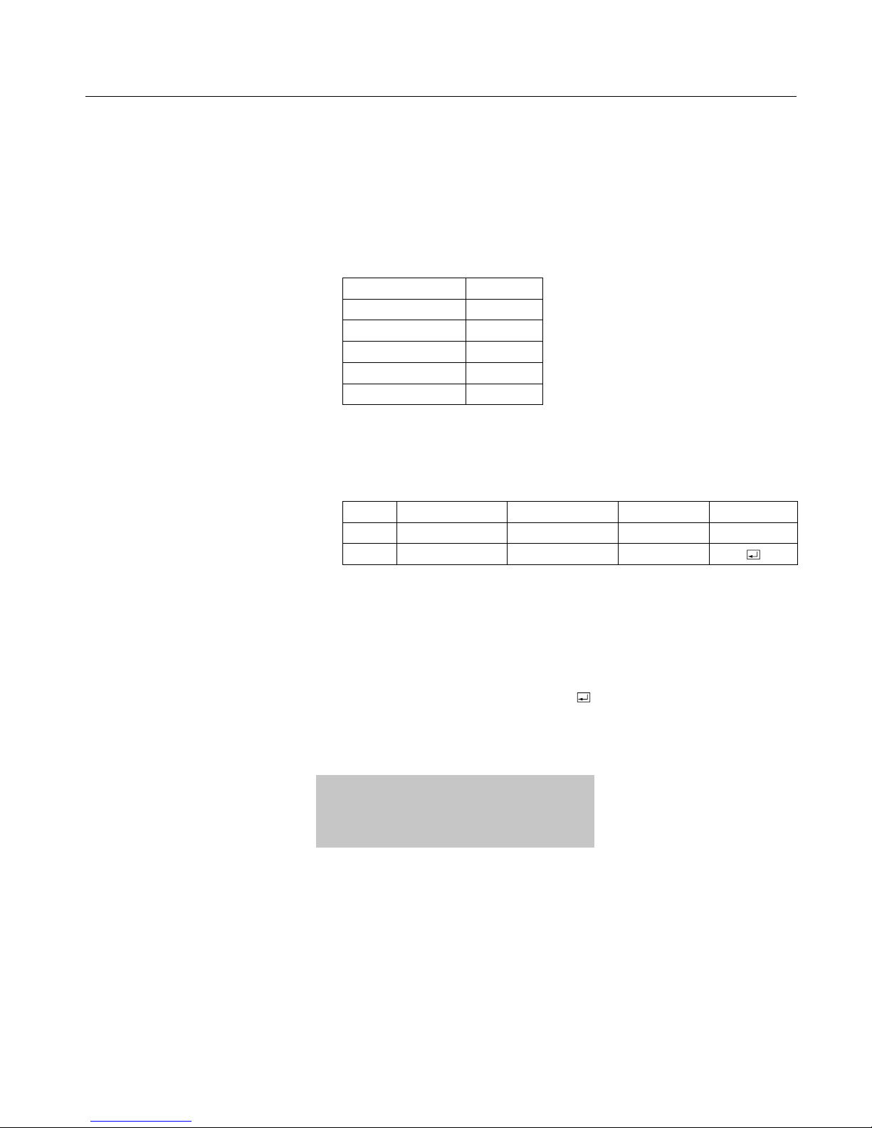
English-27
RS-232C - continued
e following control sequence is used for a single monitor
When using the following control commands, all of the daisy-chained monitors
can be controlled at the same time from the primary monitor. However, reply and
status commands will only pertain to the primary monitor, and not to the secondary
monitors.
1) Interface
PROTOCOL RS-232C
BAUD RATE 9600 [bps]
DATA LENGTH 8 [bits]
PARITY BIT NONE
STOP BIT 1 [bit]
FLOW CONTROL NONE
2) Control command diagram
e command is structured by the address code, function code, data code and end
code. e length of the command is di erent for each function.
Address Code Function Code Data Code End Code
HEX 30h 30h Function Data 0Dh
ASCII '0' '0' Function Data
[Address code] 30h 30h (In ASCII code, '0' '0') xed.
[Function code] A code of each xed control move.
[Data code] A code of each xed control data (number) and
not always indicated.
[End code] 0Dh (In ASCII code,
'' ) xed.
To control multiple monitors that are daisychained together please use the extended control
command.
Page 31
English
English-28
RS-232C - continued
3) Control sequence
1) e command from a computer to the Plasma monitor will take 400ms.
2) e Plasma monitor will send a return command 400ms* a er it has received
an encode. If the command is not received correctly,
the Plasma monitor will not send the return command.
3) e personal computer checks the command and con rms if the
command which has been sent has been executed or not.
4) is Plasma monitor sends various codes other than the return code. When
sending a control sequence via RS-232C, other codes from personal
computers will be ignored.
* e sending time of the return command may be delayed depending on the
monitor’s current activity (changing of the input signal, etc.).
[Example] Turn the power ON. (' ' is for ASCII code)
Sending commands
from the PC etc.
Status code from
Plasma monitor
Meaning
30 30 21 0D
'0' '0' '!' ' '
Command for
POWER ON
30 30 21 0D
'0' '0' '!' ' '
Command received
(Command echo back)
4) Operation commands
Operation commands execute the basic operation setting of this Plasma
monitor. It may not operate when changing the signal:
Operation ASCII HEX
POWER ON ! 21h
POWER OFF " 22h
INPUT VIDEO1 _v1 5Fh 76h 31h
INPUT VIDEO2 _v4 5Fh 76h 34h
INPUT S-VIDEO _v3 5Fh 76h 33h
INPUT DVD/HD1 _v2 5Fh 76h 32h
INPUT DVD/HD2 _v5 5Fh 76h 35h
INPUT SCART3 _v6 5Fh 76h 36h
INPUT VGA _r2 5Fh 72h 32h
INPUT RGBHV _r3 5Fh 72h 33h
INPUT DVI _r1 5Fh 72h 31h
POWER OFF command should not be used less than 1 minute a er the power is
turned on.
POWER ON command should not be used less than 1 minute a er the power is
turned o .
•
•
Page 32
English-29
Structure of the Read-command
ASCII HEX
Function Data Function Data
POWER ON vP 1 76h 50h 31h
POWER OFF vP 0 76h 50h 30h
INPUT VIDEO1 vI v1 76h 49h 76h 31h
INPUT VIDEO2 vI v4 76h 49h 76h 34h
INPUT S-VIDEO vI v3 76h 49h 76h 33h
INPUT DVD/HD1 vI v2 76h 49h 76h 32h
INPUT DVD/HD2 vI v5 76h 49h 76h 35h
INPUT SCART3 vI v6 76h 49h 76h 36h
INPUT VGA vI r2 76h 49h 72h 32h
INPUT RGBHV vI r3 76h 49h 72h 33h
INPUT DVI vI r1 76h 49h 72h 31h
Picture Mode BRIGHT vM p1 76h 4Dh 70h 31h
Picture Mode STANDARD vM p2 76h 4Dh 70h 32h
Picture Mode CINEMA1 vM p3 76h 4Dh 70h 33h
Picture Mode CINEMA2 vM p4 76h 4Dh 70h 34h
Picture Mode DEFAULT vM p5 76h 4Dh 70h 35h
5) Read command
Host computer sends the command without Data-code to monitor.
A er receiving this command, the monitor returns the command with Data-code
of current status to host computer.
<ex> When the Host computer checks the Power status of monitor, the status of
monitor is powered-on.
Command from
computer
Command from
Monitor
Detail of command
30 30 76 50 0D
‘0’’0’’v’’P’[enter]
Ask about the power
status of monitor.
30 30 76 50 31 0D
‘0’’0’’v’'P'’1’[enter]
Monitor is powered-on.
RS-232C - continued
Page 33

English
English-30
Troubleshooting
No picture
e signal cable should be properly connected to the display
card/computer.
e display card should be properly seated in its slot.
Front Power Switch and computer power switch should be in
the ON position.
Check to make sure that a supported mode has been selected
on the display card or system being used. (Please consult
display card or system manual to change graphics mode.)
Check the monitor and your display card with respect to
compatibility and recommended settings.
Check the signal cable connector for bent or pushed-in pins.
Power Button does not respond
Unplug the power cord of the monitor from the AC outlet to
turn o and reset the monitor.
Image persistence
Please be aware that Plasma Technology may experience a
phenomena known as Image Persistence. Image Persistence
occurs when a residual or “ghost” image of a previous image
remains visible on the screen. Unlike CRT monitors, Plasma
monitors’ image persistence is not permanent, but constant
images being displayed for a long period of time should be
avoided. To alleviate image persistence, turn o the monitor
for as long as the previous image was displayed. For example,
if an image was on the monitor for one hour and a residual
image remains, the monitor should be turned o for one hour
to erase the image.
NOTE: As with all personal display devices, NEC DISPLAY
SOLUTIONS recommends displaying moving images and
using a moving screen saver at regular intervals whenever the
screen is idle or turning o the monitor when not in use.
Image is unstable, unfocused or
swimming is apparent
Signal cable should be properly attached to the Plasma
monitor, computer, or other input device.
Use the OSD screen controls to focus and adjust display by
increasing or decreasing the clock phase total. When the
display mode is changed, the OSD Image Adjust settings may
need to be readjusted.
Check the monitor and your display card with respect to
compatibility and recommended signal timings.
Image of component signal is greenish
Check to see if the DVD/HD input connector is selected.
LED on monitor is not lit
(no green or red color can be seen)
Main Power Switch should be in the ON position and power
cord should be connected.
Red LED on monitor is blinking
A certain failure might have occurred, please contact your
nearest authorized NEC DISPLAY SOLUTIONS service
facility.
•
•
•
•
•
•
•
•
•
•
•
•
•
•
Display image is not sized properly
Use the OSD screen controls to increase or decrease the clock
total.
Check to make sure that a supported mode has been selected
on the display card or system being used. (Please consult
display card or system manual to change graphics mode.)
Selected resolution is not displayed properly
Use OSD information to enter Information menu and con rm
that the appropriate resolution has been selected. If not, select
appropriate resolution.
No Sound
Check to see if speaker cable is properly connected.
Check to see if mute is activated.
Check to see if volume is set at minimum.
NOTE: It is possible to play audio from a source that is di erent
from the video source.
RS-232C does not work
Check the PROTOCOL SET in the OPTION2 menu.
Remote Control does not work
Make sure the batteries are inserted properly.
Test the batteries for strength/life.
Make sure to point the remote directly at the sensor on the
monitor.
Check if the remote is in Remote ID mode.
e remote control may not function when in direct sunlight
or when there is strong illumination on the remote sensor of
the monitor.
Check the IR REMOTE setting in the OPTION3 menu.
•
•
•
•
•
•
•
•
•
•
•
•
•
Page 34
English-31
Specifi cations P42XP10
PDP Module Diagonal: 42 "/1058 mm
Pixel Pitch 0.900 mm (W)/0.676 mm (H)
Resolution 1024 x 768
Frequency Horizontal ANALOG: 15.625/15.734kHz, 31.0kHz - 108.5kHz
DIGITAL: 15.625/15.734kHz, 31.0kHz - 91.1kHz
Vertical 24Hz to 120.4Hz
Panel Display Size 922 mm (W) x 519 mm (H)
36.3 in (W) x 20.4 in (H)
Input Signals DVI DVI-D 24pin Digital RGB DVI (HDCP)
VGA60, SVGA60, XGA60, WXGA60, SXGA60, UXGA60*, 1920X1080*
VGA 15pin Mini D-sub Analog RGB 0.7V p-p, Input Impedance 75 ohm
VGA60, SVGA60, XGA60, WXGA60, SXGA60, UXGA60*
Sync Separate: TTL level (Pos./Neg.)
Composite sync on Green Video: 0.3Vp-p Neg
RGBHV BNC (R,G,B,H,V) Analog RGB 0.7V p-p, Input Impedance 75 ohm
GA60, SVGA60, XGA60, WXGA60, SXGA60, UXGA60*
Sync Separate: TTL level (Pos./Neg.)
Composite sync on Green Video: 0.3Vp-p Neg.
DVD/HD RCA (Y, Cb/Pb, Cr/Pr) Component Y : 1.0Vp-p/75ohm, Cb/Cr (Pb/Pr) : 0.7Vp-p/75 ohm
HDTV/DVD:1080p*, 1080i*, 720p@50Hz/60Hz,
576p@50Hz, 480p@60Hz, 576i@50Hz, 480i@60Hz
VIDEO1 BNC Composite 1.0V p-p Input Impedance 75 ohm
NTSC/PAL(B, G, M, N)/SECAM/4.43NTSC/PAL60
VIDEO2 RCA Composite 1.0V p-p Input Impedance 75 ohm
NTSC/PAL(B, G, M, N)/SECAM/4.43NTSC/PAL60
S-VIDEO DIN 4 pin S-VIDEO Y: 1.0Vp-p/75ohm C: 0.286Vp-p/75 ohm(NTSC),
0.3Vp-p/75ohm(PAL/SECAM)
NTSC/PAL(B, G, M, N)/SECAM/4.43NTSC/PAL60
Output Signal (VIDEO1
and VGA can also be used
as OUTPUT terminals)
VGA 15pin Mini D-sub Analog RGB Analog RGB Video: 0.7V p-p with 75 ohm terminated
Separate HV sync: TTL level (Pos / Neg)
VIDEO1 BNC Composite Composite 1.0V p-p with 75 ohm terminated
Audio AUDIO Input RCA (L/R) X3 Analog Audio Stereo L/R 0.5Vrms
Speaker Output External Speaker Jack 8W + 8W (8 ohm)
External Control RS-232C: IN 9 Pin D-sub
RS-232C: OUT 9 Pin D-sub (daisy chain)
Power Supply 4.4-1.8A@100-240V AC, 50/60Hz
Operational Environment Temperature 0˚ to 40˚C / 32˚ F to 104˚ F
Humidity 20% to 80% (without condensation)
Storage Environment Temperature -10˚C to 50˚C / 14˚ F to 122˚F
Humidity 10 - 90% (without condensation)/ 90% - 2% x (Temp - 40°C) regarding over 40°C
Dimensions Net 1036mm(W) x 644mm(H) x 127mm(D) / 40.8"(W) x 25.4"(H) x 5.0"(D)
Gross 1220mm(W) x 900mm(H) x 360mm(D) / 48.0"(W) x 35.4"(H) x 14.2"(D)
Wei g h t
(without speaker and stand )
Net 33.5 kg / 73.9 lbs
Gross 41.5 kg / 91.5 lbs
VESA compatible arm
mounting interface
700mm x 300mm 4 Holes (screw M8 Depth 16mm)
Complied Regulatory
and Guidelines
UL 60950-1/CSA C22.2 No.60950-1/EN60950-1/IEC60950-1
FCC-B/DOC-B/EN55022-B/EN55024/EN61000-3-2/EN61000-3-3/CE/C-Tick
Power Management VESA DPM (Separate HV Sync. only)
Plug & Play VESA DDC2B
Accessories Remote control, AA Batteries, Power cord, Users Manual (CD-ROM),
Start Up Guide (Paper / CD-ROM), Main Power Switch cover and screw, Cable clamps
*Compressed Image
Page 35
English
English-32
Specifi cations P50XP10
PDP Module Diagonal: 50"/1269 mm
Pixel Pitch 0.81 mm (W)/0.81 mm (H)
Resolution 1365 x 768
Frequency Horizontal ANALOG: 15.625/15.734kHz, 31.0kHz - 108.5kHz
DIGITAL: 15.625/15.734kHz, 31.0kHz - 91.1kHz
Vertical 24Hz to 120.4Hz
Panel Display Size 1106 mm (W) x 622 mm (H)
43.5 in (W) x 24.5 in (H)
Input Signals DVI DVI-D 24pin Digital RGB DVI (HDCP)
VGA60, SVGA60, XGA60, WXGA60, SXGA60, UXGA60*, 1920X1080*
VGA 15pin Mini D-sub Analog RGB 0.7V p-p, Input Impedance 75 ohm
VGA60, SVGA60, XGA60, WXGA60, SXGA60, UXGA60*
Sync Separate: TTL level (Pos./Neg.)
Composite sync on Green Video: 0.3Vp-p Neg
RGBHV BNC (R,G,B,H,V) Analog RGB 0.7V p-p, Input Impedance 75 ohm
VGA60, SVGA60, XGA60, WXGA60, SXGA60, UXGA60*
Sync Separate: TTL level (Pos./Neg.)
Composite sync on Green Video: 0.3Vp-p Neg.
DVD/HD RCA (Y, Cb/Pb, Cr/Pr) Component Y : 1.0Vp-p/75ohm, Cb/Cr (Pb/Pr) : 0.7Vp-p/75 ohm
HDTV/DVD:1080p*, 1080i*, 720p@50Hz/60Hz,
576p@50Hz, 480p@60Hz, 576i@50Hz, 480i@60Hz
VIDEO1 BNC Composite 1.0V p-p Input Impedance 75 ohm
NTSC/PAL(B, G, M, N)/SECAM/4.43NTSC/PAL60
VIDEO2 RCA Composite 1.0V p-p Input Impedance 75 ohm
NTSC/PAL(B, G, M, N)/SECAM/4.43NTSC/PAL60
S-VIDEO DIN 4 pin S-VIDEO Y: 1.0Vp-p/75ohm C: 0.286Vp-p/75 ohm(NTSC),
0.3Vp-p/75ohm(PAL/SECAM)
NTSC/PAL(B, G, M, N)/SECAM/4.43NTSC/PAL60
Output Signal (VIDEO1
and VGA can also be used
as OUTPUT terminals)
VGA 15pin Mini D-sub Analog RGB Analog RGB Video: 0.7V p-p with 75 ohm terminated
Separate HV sync: TTL level (Pos / Neg)
VIDEO1 BNC Composite Composite 1.0V p-p with 75 ohm terminated
Audio AUDIO Input RCA (L/R) X3 Analog Audio Stereo L/R 0.5Vrms
Speaker Output External Speaker Jack 8W + 8W (8 ohm)
External Control RS-232C: IN 9 Pin D-sub
RS-232C: OUT 9 Pin D-sub (daisy chain)
Power Supply 6.0-2.6A@100-240V AC, 50/60Hz
Operational Environment Temperature 0˚ to 40˚C / 32˚ F to 104˚ F
Humidity 20% to 80% (without condensation)
Storage Environment Temperature -10˚C to 50˚C / 14˚ F to 122˚F
Humidity 10 - 90% (without condensation)/ 90% - 2% x (Temp - 40°C) regarding over 40°C
Dimensions Net 1221mm(W) x 743mm(H) x 127mm(D) / 48.1"(W) x 29.3"(H) x 5.0"(D)
Gross 1400mm(W) x 980mm(H) x 360mm(D) / 55.1"(W) x 38.6"(H) x 14.2"(D)
Wei g h t
(without speaker and stand )
Net 47.5 kg / 104.7 lbs
Gross 57.5 kg / 126.8 lbs
VESA compatible arm
mounting interface
700mm x 300mm 4 Holes (screw M8 Depth 16mm)
Complied Regulatory
and Guidelines
UL 60950-1/CSA C22.2 No.60950-1/EN60950-1/IEC60950-1
FCC-B/DOC-B/EN55022-B/EN55024/EN61000-3-2/EN61000-3-3/CE/C-Tick
Power Management VESA DPM (Separate HV Sync. only)
Plug & Play VESA DDC2B
Accessories Remote control, AA Batteries, Power cord, Users Manual (CD-ROM),
Start Up Guide (Paper / CD-ROM), Main Power Switch cover and screw, Cable clamps
*Compressed Image
Page 36
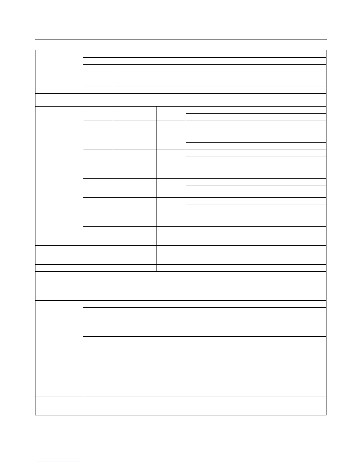
English-33
Specifi cations P60XP10
PDP Module Diagonal: 60"/1514 mm
Pixel Pitch 0.966 mm (W)/0.966 mm (H)
Resolution 1366 x 768
Frequency Horizontal ANALOG: 15.625/15.734kHz, 31.0kHz - 108.5kHz
DIGITAL: 15.625/15.734kHz, 31.0kHz - 91.1kHz
Vertical 24Hz to 120.4Hz
Panel Display Size 1320 mm (W) x 742 mm (H)
51.9 in (W) x 29.2 in (H)
Input Signals DVI DVI-D 24pin Digital RGB DVI (HDCP)
VGA60, SVGA60, XGA60, WXGA60, SXGA60, UXGA60*, 1920X1080*
VGA 15pin Mini D-sub Analog RGB 0.7V p-p, Input Impedance 75 ohm
VGA60, SVGA60, XGA60, WXGA60, SXGA60, UXGA60*
Sync Separate: TTL level (Pos./Neg.)
Composite sync on Green Video: 0.3Vp-p Neg
RGBHV BNC (R,G,B,H,V) Analog RGB 0.7V p-p, Input Impedance 75 ohm
VGA60, SVGA60, XGA60, WXGA60, SXGA60, UXGA60*
Sync Separate: TTL level (Pos./Neg.)
Composite sync on Green Video: 0.3Vp-p Neg.
DVD/HD RCA (Y, Cb/Pb, Cr/Pr) Component Y : 1.0Vp-p/75ohm, Cb/Cr (Pb/Pr) : 0.7Vp-p/75 ohm
HDTV/DVD:1080p*, 1080i*, 720p@50Hz/60Hz,
576p@50Hz, 480p@60Hz, 576i@50Hz, 480i@60Hz
VIDEO1 BNC Composite 1.0V p-p Input Impedance 75 ohm
NTSC/PAL(B, G, M, N)/SECAM/4.43NTSC/PAL60
VIDEO2 RCA Composite 1.0V p-p Input Impedance 75 ohm
NTSC/PAL(B, G, M, N)/SECAM/4.43NTSC/PAL60
S-VIDEO DIN 4 pin S-VIDEO Y: 1.0Vp-p/75ohm C: 0.286Vp-p/75 ohm(NTSC),
0.3Vp-p/75ohm(PAL/SECAM)
NTSC/PAL(B, G, M, N)/SECAM/4.43NTSC/PAL60
Output Signal (VIDEO1
and VGA can also be used
as OUTPUT terminals)
VGA 15pin Mini D-sub Analog RGB Analog RGB Video: 0.7V p-p with 75 ohm terminated
Separate HV sync: TTL level (Pos / Neg)
VIDEO1 BNC Composite Composite 1.0V p-p with 75 ohm terminated
Audio AUDIO Input RCA (L/R) X3 Analog Audio Stereo L/R 0.5Vrms
Speaker Output External Speaker Jack 8W + 8W (8 ohm)
External Control RS-232C: IN 9 Pin D-sub
RS-232C: OUT 9 Pin D-sub (daisy chain)
Power Supply 7.8-3.2A@100-240V AC, 50/60Hz
Operational Environment Temperature 0˚ to 40˚C / 32˚ F to 104˚ F
Humidity 20% to 80% (without condensation)
Storage Environment Temperature -10˚C to 50˚C / 14˚ F to 122˚F
Humidity 10 - 90% (without condensation)/ 90% - 2% x (Temp - 40°C) regarding over 40°C
Dimensions Net 1447(W)mm x 871mm(H) x 127mm(D) / 57.0"(W) x 34.3"(H) x 5.0"(D)
Gross 1620mm(W) x 1100mm(H) x 360mm(D) / 63.8"(W) x 43.3"(H) x 14.2"(D)
Wei g h t
(without speaker and stand )
Net 68.5 kg / 151.0 lbs
Gross 81.0 kg / 178.6 lbs
VESA compatible arm
mounting interface
700mm x 300mm 4 Holes (screw M8 Depth 16mm)
Complied Regulatory
and Guidelines
UL 60950-1/CSA C22.2 No.60950-1/EN60950-1/IEC60950-1
FCC-B/DOC-B/EN55022-B/EN55024/EN61000-3-2/EN61000-3-3/CE/C-Tick
Power Management VESA DPM (Separate HV Sync. only)
Plug & Play VESA DDC2B
Accessories Remote control, AA Batteries, Power cord, Users Manual (CD-ROM),
Start Up Guide (Paper / CD-ROM), Main Power Switch cover and screw, Cable clamps
*Compressed Image
Page 37
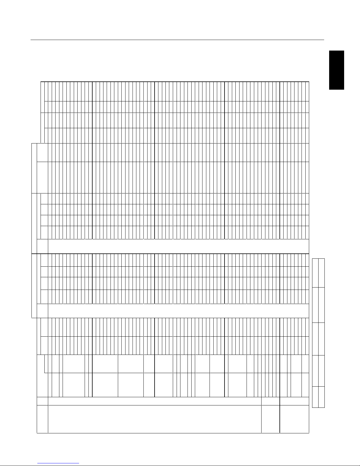
English
English-34
Specification of the signal
Sig.
EURT
M
O
OZL
LU
FLA
MR
O
N
TU
P
N
I
E
U
RT
M
O
O
Z
L
LUF
L
A
MR
O
N
T
U
P
N
I
.
q
e
r
f
H
.
q
e
r
fVnoi
t
u
l
o
s
eR
no. m
e
tI
.
o
N.r
G
VH
)L
A
E
R(
)
9
:
61
(
)
3
:
4
(l
a
n
i
m
r
e
t
)
L
A
E
R
(
)
9
:6
1
(
)
3
:
4
(
l
animret)z
H
k
(
)ZH
(
epyTlan
g
i
S
H X V
IBM PC/AT 1
640 X 400 400line 70.1 31.5
VGA
-- Yes -- - - DVI
-- -- -- - -
Yes Yes
Neg. Neg. 1 640X400
Compatible
2 720 X 400 400line 70.1 31.5
RGBHV -- Yes -- Yes (DVI-PC)
-- Yes -- Yes Yes Yes
Neg. Neg. 1 720X400
Computers s
e
Y-
-
s
e
Y
--
s
e
Y-
-s
eY
-
-
9
.
7
3
58
3
Yes Yes
Neg. Pos. - - - -
4 720 X 350 350line s
e
Y-
-s
eY--
s
e
Y--
s
eY
-
-
5
.
1
3
1
.07 Yes Yes
Neg. Neg. 1 720X350
5 640 X 480 VGA 59.9 31.5 Yes Yes Yes Yes Yes Yes Yes Yes
Yes Yes
Neg. Neg. 2 640X480
se
Y
s
e
Y
s
eY
s
e
Y
se
Y
s
eYs
e
Y
s
e
Y9.738.276
Yes Yes
Neg. Neg. - - - -
s
e
Y
s
e
Y
s
eY
s
e
Yse
Y
s
e
Y
s
e
Y
se
Y
5
.
7
3
5
77 Yes Yes
Neg. Neg. - - - -
s
e
Y
s
eYse
Y
seYs
e
Y
se
Yse
Y
seY3.34588 Yes Yes Neg. Neg. - - - -
se
Y
s
e
Y
s
eY
s
e
Y
s
eY
s
e
Y
se
Ys
e
Y1.154.0019 Yes Yes
Neg. Neg. - - - -
s
e
Y
s
eY
s
eY
s
e
Y
se
Y
s
eYs
e
Y
s
e
Y3.1
6
4
.02101 Yes Yes
Neg. Neg. - - - -
11 848 X 480 Wide-VGA
s
e
Y-
-s
eY
-
-
s
e
Y-
-s
e
Y
--13
0
6
Yes Yes
Pos. Pos. 2 848X480
12
852 X 480 Wide-VGA s
e
Y--
s
e
Y-
-s
e
Y-
-s
e
Y-
-7.1306 Yes Yes
Neg. Neg. 2 852X480
13
800 X 600 SVGA 56.3 35.2 Yes Yes Yes Yes Yes Yes Yes Yes
Yes Yes
Pos. Pos. - - - -
se
Y
s
eY
se
Y
se
Y
se
Ys
e
Y
se
Y
se
Y9.
7
3
3.
0
64
1 Yes Yes
Pos. Pos. - - - -
s
e
Yse
Y
s
e
Y
s
e
Y
se
Y
se
Yse
Y
s
eY1.842.2751
Yes Yes
Pos. Pos. - - - -
s
e
Y
s
e
Y
s
e
Y
s
eY
s
e
Y
s
eYs
eY
seY
9
.645761
Yes Yes
Pos. Pos. - - - -
s
e
Y
se
Y
s
eY
s
e
Y
se
Ys
e
Y
s
e
Y
se
Y
7.3
5
1
.
5
8
71
Yes Yes
Pos. Pos. - - - -
se
Y
s
e
Yse
Y
s
e
Y
se
Y
se
YseY
s
eY
3
68.
9
98
1
Yes Yes
Pos. Pos. - - - -
s
e
Y
s
e
Yse
Y
s
e
Y
s
e
Y
s
eY
seYs
e
Y7
.
57
0
219
1
Yes Yes Pos. Pos. - - - -
20 1024 X 768 XGA 60 48.4 Yes Yes Yes - - Yes Yes Yes - -
Yes Yes
Neg. Neg. 3 1024X768
--
s
eYs
e
Y
s
e
Y
--
s
eY
s
eYseY
5
.651.0712
Yes Yes
Neg. Neg. 5 1024X768
--
s
e
Y
s
eY
s
e
Y--
se
Ys
e
Y
seY
9.75
9.1722
Yes Yes
Neg. Neg. 6 1024X768
-
-
s
e
Yse
Y
s
e
Y
-
-
s
e
Yse
Y
s
e
Y06
5732
Yes Yes
Pos. Pos. - - - -
-
-
s
e
Yse
Y
s
eY-
-
s
eYs
eY
se
Y7.865842
Yes Yes
Pos. Pos. - - - -
-
-
s
e
Y
s
eY
s
e
Y
-
-se
Y
s
eY
se
Y
5
.086
.001
52
Yes - -
Neg. Neg. - - - -
-
-
s
e
Y
se
Y
s
e
Y
--seYs
e
Yse
Y
5.594
.91
162 Yes - -
Neg. Neg. - - - -
27 1152 X 864 XGA 60 53.7 Yes Yes Yes - - Yes Yes Yes - -
Yes Yes Pos. Neg. - - - -
-
-s
eY
s
e
Y
s
e
Y
--
se
YseYseY9.462782
Yes Yes
Pos. Neg. - - - -
-
-
s
e
Yse
Y
s
eY
--
s
eYseY
se
Y5.765792
Yes Yes
Pos. Pos. - - - -
30
1280 X 768 Wide-XGA -----
-
--
-
--
-
seY
-
-1
.
5
4
2
.
6
5
Yes Yes
Pos. Pos. - - - -
-
-
-
-
seY------seY--8
48.9513
Yes Yes
Pos. Neg. 3 1280X768-1
-
-
-
-
seY--
-
---seY
-
-8
.
7
4
9
.
9
52
3
Yes Yes
Neg. Pos. 3 1280X768-2
-
-
-
-
s
e
Y
-
--
-
--
s
eY-
-
6
58.
9
63
3
Yes Yes
Neg. Pos. 5 1280X768
-
--
-
s
e
Y--
---
-
seY--8.75274
3 Yes Yes
Neg. Pos.
6 1280X768
35
1280 X 800 Wide-XGA
-
-
-
-
s
e
Y
-
----
-
s
e
Y--
7
.94
8
.95 Yes Yes
Neg. Pos. 4 1280X800
36 1280 X 854 Wide-XGA
-
-
-
-s
e
Y------seY--1.3506 Yes Yes
Neg. Neg. - - - -
37
1280 X 960 Wide-XGA --
s
e
Ys
e
Yse
Y--
s
e
Y
seYseY
0
606 Ye s Yes
Pos. Pos. - - - -
-
-seYseYseY--2*seY
2*seY2*seY9
.58588
3 Yes - - Pos. Pos. - - - -
39
1360 X 768 Wide-XGA -
-
-
-se
Y
-
--
--
-
s
e
Y
-
-
7.
7
40
6 Yes Yes
Pos. Pos. 3 1360X768
40
1376 X 768 Wide-XGA -
-
-
-
s
e
Y
-
-
--
-
-se
Y
--3
.
8
4
9
.
9
5 Yes Ye s Neg. Pos. 3 1376X768
41
1280 X 1024 SXGA
60 64 Yes *1 Yes Yes - - Yes *1 Yes Yes - - Ye s Yes
Pos. Pos. 9 1280X1024
--seY
s
e
Y
1*se
Y-
-se
Y
s
e
Y1
*
s
e
Y
08
5724
Yes - - Pos. Pos. - - - -
--seYseY1*seY--2
*
s
e
Y2*s
e
Y2*1*s
e
Y1.1958
3
4 Yes - - Pos. Pos. - - - -
-
-
-
-
-
-
-
-
-
-
2*seY
2
*
s
e
Y
2
*
1*seY
5
.8011.0014
4
Yes - - Pos. Pos. - - - -
45
1400 X 1050 SXGA+
--
se
YseYse
Y
-
-
s
e
Yse
Y
seY460
6
Yes - -
Neg. Pos. 9 1400X1050
-
-
se
Ys
e
Yse
Y
--
se
YseY
s
eY3.560664
Yes - -
Neg. Pos. 7 1400X1050
--seY
s
eYseY--2*seY2*
s
eY2*
se
Y3
.28
9.
4
774 Yes - - Neg. Pos. - - - -
-
-
-
------
-
2*seY
2
*
s
e
Y2
*
se
Y9.
3
9
5
8
8
4 Yes - -
Neg. Pos. - - - -
49
1680 X 1050 Wide-SXGA
--
-
-seY-----
-
s
e
Y
-
-
3
.5606 Yes - - Neg. Pos. 7 1680X1050
50
1600 X 1200 UXGA
60 75 Yes *2 Yes *2 Yes *2 - - Yes Yes Yes - - Yes - - Pos. Pos. 8 1600X1200
----------2
*
s
e
Y2*s
e
Y2*se
Y3.1856
15 Yes - -
Pos. Pos. - - - -
---
-
-
-
--
--2*s
e
Y2*seY2*se
Y
5
.780725 Yes - - Pos. Pos. - - - -
------
-
---2*seY2*seY2*seY8.3957
3
5 Yes - - Pos. Pos. - - - -
-
-
--
-
--
---2
*
s
e
Y2*s
e
Y2*se
Y3.
6
0
1
5
8
4
5 Yes - - Pos. Pos. - - - -
55
1920 X 1080
----seY-----
-
----2.6505 Yes - - Pos. Pos. - - - -
---
-
seY
-
--
-
-----
-5
.
7
60
6
65 Yes - - Pos. Pos. - - - -
57 1920 X 1200 Wide-UXGA -
--
-
-
--
-
----2*seY--6.
4
79.
9
5
Yes - -
Neg. Pos. 8 1920X1200
58 1920 X 1200RB Wide-UXGA ----seY-
-----2*seY--4706 Yes - - Neg. Pos. - - - -
Apple Macintosh®
81
640 X 480 Mac13" ---------
-
s
e
Ys
e
Y
s
eY53
7
.
6
6 Yes Ye s Sync on G Sync on G - - - -
82 832 X 624 Mac16" 74.6 49.7 Yes Yes Yes - - - - - - - - - -
Yes Yes
Sync on G Sync on G - - - -
83
1024 X 768 Mac19"
74.9 60.2 Yes Yes Yes - - - - - - - - - - Yes Yes Sync on G Sync on G - - - -
84
1152 X 870 Mac21" 75.1 68.7 Yes Yes Yes -- -- -- -- - - Yes Yes Sync on G Sync on G - - - -
85 1440 X 900 Apple17 ----
s
eY--
-
-
-
-seY--9
.55
9
.95 Yes Yes Neg. Pos. - - - -
EWS Series
91
Work Station EWS4800 60 64.6 Yes *1 Yes Yes - - Yes *1 Yes Yes - - Ye s - - Neg. Neg. - - - -
92 1280 X 1024
71.2 75.1 Yes *1 Yes Yes - - Yes *1 Yes Yes - - Yes - - Neg. Neg. - - - -
93
1280 X 1024 HP
72 78.1 Yes *1 Yes Yes - - Yes *1 Yes Yes - - Yes - - - - - - - -
94
1152 X 900 SUN
66 61.8 Yes Yes Yes - - Yes Yes Yes - -
Yes Yes C Sync C Sync - - - -
95
1152 X 900
76 71.7 Yes Yes Yes - - Yes Yes Yes - - Yes Yes
C Sync C Sync - - - -
96 1280 X 1024
76.1 81.1 Yes *1 Yes Yes - - Yes *1 Yes Yes - -
Yes - - C Sync C Sync - - - -
97
1024 X 768 SGI 60 49.7 Yes Yes Yes - - Yes Yes Yes - - Yes - - - - 4 1024X768
98
1280 X 1024
60 63.9 Yes *1 Yes Yes - - Yes *1 Yes Yes - -
Yes - - - - - - - -
l
at
i
g
i
Dgolan
A
TEXT INSERT
Sync polarity RGB select
E
ZI
S
E
ZIS
TOP1-3/MID HIGH/
MID LOW/BOTTOM1-3
Left/Right
P42XP10 Supported Resolutions (PC)
- - NOR MAL (4:3 ) FULL (16:9) ( *1) ( *2)
Not Suppor ted 768 pixels x 768 l ines 102 4 pixels x 768 lines A spect ratio is 5 :4 (720x768 ) Rough Samp ling
Page 38
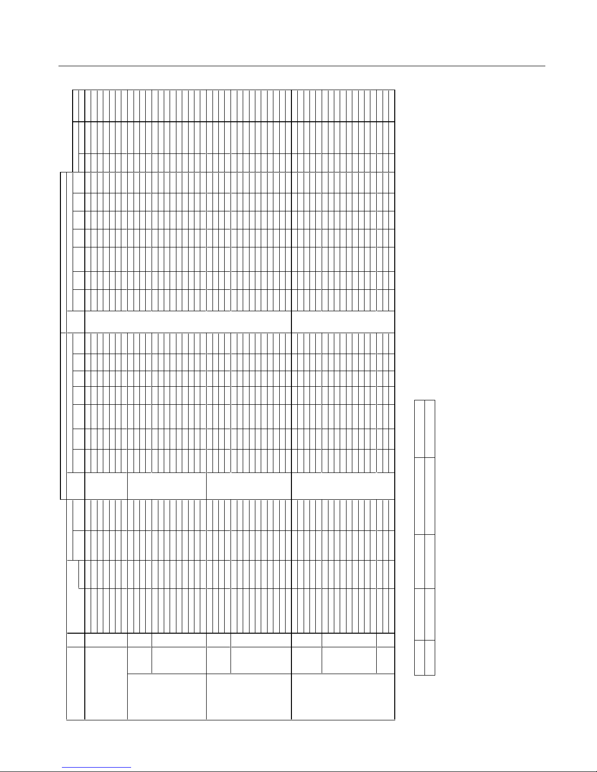
English-35
P42XP10 Supported Resolutions (Video)
Specification of the signal
Sig.
tc
e
le
s
D
H
R
ED
NU
1
:
5
3
.
2
9
:
4
1
M
OO
Z
C
I
MANY
D
L
L
U
FL
A
MR
O
N
TUP
N
I
REDN
U
1
:
5
3
.
2
9
:
41M
O
O
Z
C
I
M
A
N
Y
D
L
L
U
F
L
A
MR
O
N
T
U
P
N
I
.
q
er
f
H.
q
e
r
f
V
n
o
i
t
ulo
s
eR
no.
H X V Signal Type (Hz) (kHz) terminal (4:3) (16:9)
(non-linear)
SCAN terminal (4:3) (16:9)
(non-linear)
SCAN Gr. No. Item Item
Video 101 3.58NTSC
59.9 15.8
Video1
Yes Yes Yes Yes Yes Yes Yes *3 -- -- -- -- -- -- -- -- -- - -
Composite / S 102
4.43NTSC
59.9 15.8 Video2
Yes Yes Yes Yes Yes Yes Yes *3 -- -- -- -- -- -- -- -- -- - -
103 PAL
50 15.6
S-Video
Yes Yes Yes Yes Yes Yes Yes *3 -- -- -- -- -- -- -- -- -- - -
104 PAL60 -
-
-
--
-
-
-
-
-
--
--
-
-
-
-
--
3*se
Y
se
Y
s
eY
s
e
Yse
Y
s
e
Y
s
eY
8.5
1
9
.
9
5
105
PAL-N -
-
---
-
---
--
-
-
-
-
-
-
-
--
3*s
e
Y
s
e
Y
s
eY
s
eYs
e
Ys
e
Y
s
eY
6
.
5
10
5
106 PAL-M -
-
-
--
-
--
-
-
--
-
-
-
-
-
-
-
-
3*s
e
Y
s
e
Y
s
eY
s
e
Yse
Y
s
eY
seY8.5
1
9.95
107 SECAM -
-
--
--
--
--
-
-
-
-
-
-
-
-
--
3*s
e
Y
s
e
Y
s
eY
s
e
Y
s
eYse
Ys
eY
6
.
5
1
0
5
Y,Pb(Cb),Pr(Cr) SD 111 480I 59.9 15.8
DVD/HD1 Yes Yes Yes Yes Yes Yes Yes *3 - - - - - - - - - - - - - - - - - - - -
112 576I 50 15.6
DVD/HD2
Yes Yes Yes Yes Yes Yes Yes *3 -- -- -- -- -- -- -- -- -- - -
113 480P --
-
---
-
-
--
-
-
------
-
-
3
*
s
eYse
Y
se
Y
s
e
Y
s
eYse
Yse
Y
5
.
1
3
9
.95
114
576P -
-
-
--
-
--
-
-
-
-
---
-
-
-
-
-
3
*
s
eYseYseYs
e
Y
s
eYs
eYs
eY3.1305
HD
115 720P ---
--
-
--
-
-
-
-
-------
-
3
*
s
eY
s
eY-
-
-
-s
eYse
Y
-
-
5.
7
3
0
5
116
720P -----
-
-
-
--
-
--
-
------3
*s
eY
s
eY--
--
s
eYse
Y
-
-5
4
0
6
117 1080I
------
-
-
--
-
-
------
-
-
3
*
s
eY
s
eY
-
-
-
-s
eYs
eY
--
1
.
8
2
0
5
118 1080I
-
-
-
---
-
-
--
--
-
-
-
-
-
-
-
-
3
*
s
eY
s
eY-
--
-s
eYs
e
Y
-
-
8.
330
6
119 1080P --
-
--
-
--
-
-
-
-
------
-
-
3
*
s
eYse
Y-
-
--
s
eYse
Y
--3.65
0
5
120 1080P
-
------
-
------
-
-
-
---3*se
Y
seY----
s
eYse
Y
--5.7606
121 1080P
-
-
--
--
-
-
--
-
-
--
-
-
-
-
--
3*se
Y
se
Y-
-
-
-se
YseY-
-
8.
3
303
122 1080P
-
-
-
--
-
--
-
-
--
-
-
-
-
-
-
--
3
*
se
Y
se
Y
--
-
-se
Y
seY-
-7242
123 1080P
-
-
-
--
-
-
--
-
--
-
-
-
-
-
-
-
-
3*s
e
Y
s
e
Y-
-
--seYs
eY
--8
2
5
2
RGB(Video signal) SD 131
480I *4 59.9 15.8 VGA
Yes Yes Yes Yes Yes Yes Yes *3 -- -- -- -- -- -- -- -- -- - -
132 576I *4 50 15.6 RGBHV Yes Yes Yes Yes Yes Yes Yes *3 - - - - - - - - - - - - - - - - - - - -
133 480P 59.9 31.5 (SCART1-3) Yes Yes Yes Yes Yes Yes Yes *3 - - - - -- - - - - - - - - 2 480P - -
134 576P
-
-
-
-
-
-
--
-
-
--
-
-
-
-
-
-
-
-
3
*
s
eYseY
s
e
Y
s
e
Yse
Y
seY
s
eY3
.
1
3
0
5
HD 135
720P
-
-
-
--
-
--
-
-
-
-
---
-
-
-
-
-
3
*seYse
Y-
-
--
s
eYs
e
Y--5.7
3
05
136
720P -------
-
--
-
---------
3
*
s
e
Y
s
eY-
-
--se
Y
s
e
Y--5
4
0
6
137
1080I -
-
-
---
--
--
--
-
-
-
-
-
-
-
-
3
*
s
eY
s
e
Y-
-
-
-
s
e
Y
s
e
Y--1
.
8
2
0
5
138 1080I B0
8
0
1
-
---
-
-
--
-
-
------
-
-
3
*
s
eYse
Y
-
---seYse
Y
-
-
8.
3
306
139
1080P --
-
----
-
--
-
-------
-
-3*seYse
Y
---
-
s
e
Y
s
e
Y
-
-3
.
6
5
0
5
140
1080P
-
-
--
--
--
--
-
-
-
-
-
-
-
-
--
3*s
e
Y
s
e
Y--
-
-seY
s
eY
-
-
5
.760
6
141
1080P
-
-
---
-
-
--
--
-
--
-
-
-
-
--
3*se
Y
se
Y---
-s
eYs
e
Y-
-
8.33
0
3
142
1080P
-
-
-
--
-
-
--
-
-
-
--
-
-
-
-
-
-
3*se
Y
se
Y-
-
--
s
eYs
e
Y
--7242
143 1080P -------
-
------------
3
*seYseY----seYseY--8252
144
1080A/540P RCA STB
A
08
0
1
---
--
--
-
-
-
-
-
----
-
-
3*se
Y
s
eY
-
-
-
-
s
e
Y
s
e
Y
-
-8
.
3
3
0
6
Digital SD
161
640 X 480P 59.9 / 60.0 31.5 / 31.5 - - - - - - - - - - - - - -
DVI
Yes *3 Yes *3 Yes *3 Yes *3 Yes *3 Yes *3 Yes *3 - - - - - -
(EIA/CEA-861)
162
720 (1440) X 480I 59.9 / 60.0 15.7 / 15.8 - - - - - - - - - - - - - -
(DVI-HD) Yes Yes Yes Yes Yes Yes Yes *3 - - -- - -
163
720 X 480P 59.9 / 60.0 31.5 / 31.5 -- -- -- -- -- -- -- Yes Yes Yes Yes Yes Yes Yes *3 -- -- - -
164 720 (1440) X 576I
-
-
-
-
-
-
3*s
e
Y
se
Y
s
e
Y
se
Y
s
e
Y
s
e
Ys
eY
-
---
-
-
-
-
--
-
--
-
6.
5
1
0
5
165 720 X 576P
-
-
-
---
3*se
Y
se
Y
se
Y
s
e
Y
s
eY
se
Y
s
eY-
-
-
-----------3.1305
HD 166
1280 X 720P
59.9 / 60.0 45.0 / 45.0 -- -- -- -- -- -- -- -- Yes Yes -- -- Yes Yes *3 -- -- - -
167 1920 X 1080I 59.9 / 60.0 33.7 / 33.8 - - - - - - - - - - - - - - - - Yes Yes - - - - Yes Yes *3 - - - - - -
168 1920 X 1080P 59.9 / 60.0 67.4 / 67.5 - - - - - - - - - - - - - - - - Yes Yes - - - - Yes Yes *3 - - - - - -
169 1280 X 720P -
-
-
--
-
3
*
s
eY
s
e
Y
-
-
-
-
se
Y
s
eY
-
-
-
--
-
-
-
-
-
--
-
--
-
5.73
0
5
170
1920 X 1080I -----
-
3*s
eY
s
eY
-
--
-se
Ys
e
Y
------
-
---
-
--
--
-1
.
8
2
0
5
171 1920 X 1080P ---
--
-
3*s
e
Y
s
eY-
-
-
-se
Y
s
eY
-
-
-
-----
-
-
--
-
--
-
3.
6
5
0
5
172 1920 X 1080P
-
-----3*seYseY----s
e
YseY----
------------8.3303
173 1920 X 1080P
-
-
-
--
-
3*se
Y
s
eY-
--
-s
e
Y
s
eY--
-
---
-
---
-
-
--
--7
2
4
2
174 1920 X 1080P -
-
---
-
3*se
Y
s
eY
-
--
-s
e
Ys
eY
-----------
-----8252
Native
191
1366 X 768
-
---
-
-
-
--
-
-
-
-
-
-
-
3*se
Y----------------3
.74
06
Resolution 192 1024 X 768 -
-
-
-
-
-
-
--
-
-
-
-
--
-
3*
se
Y
-
---
-
-----------3.7406
193 853 X 480 -
--
-
-
-
-
--
-
-
-
-
--
-3
*
seY
---
-
-------
--
---0306
SIZE SIZE
RGB select
A
nal
o
g
Digita
l
- - NORMAL(4:3) FULL(16:9) (*3) (*4)
Not Suppor ted 768 pixels x 768 l ines 102 4 pixels x 768 lines Di splayed by Under scan mode (100% ) SCAR T input available
Page 39
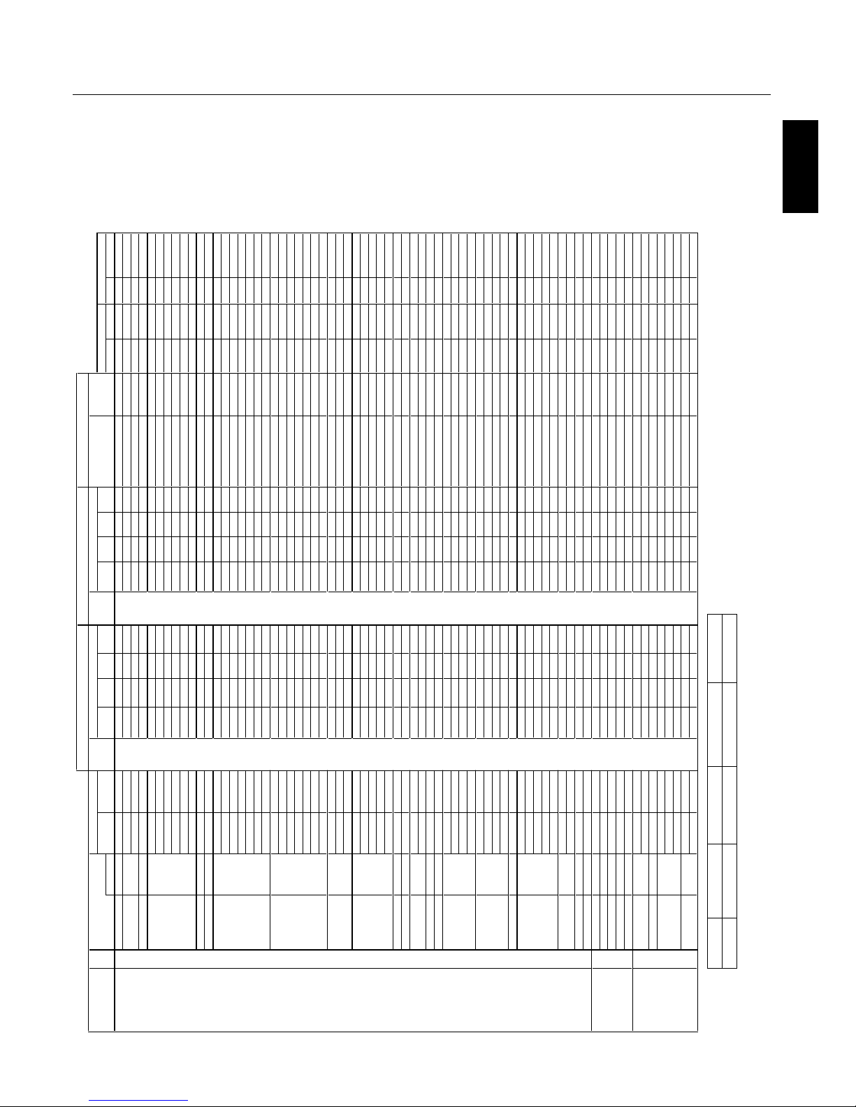
English
English-36
Specification of the signal
Sig.
E
U
R
TMOO
Z
L
L
UFL
A
M
RONT
U
P
N
I
E
U
R
T
MOO
ZL
LUF
L
A
M
RO
N
T
UP
N
I
.
q
er
f
H
.
q
er
fV
n
oitul
o
seR
no.
m
e
t
I
.
o
N
.
rG
VH)
L
AE
R
(
)
9
:
6
1(
)
3
:
4
(
l
a
n
i
mr
e
t)
L
A
E
R
(
)
9
:
6
1
()
3
:
4
(
l
a
n
i
mr
e
t)
z
H
k
(
)Z
H
(
e
p
yTl
a
ng
i
S
H X V
IBM PC/AT
1
640 X 400 400line
70.1 31.5
VGA -- Yes -- - - DVI
-- -- -- - -
Yes Yes
Neg. Neg. 1 640X400
Compatible 2 720 X 400 400line 70.1 31.5 RGBHV -- Yes -- Yes
(DVI-PC)
-- Yes -- Yes
Yes Yes
Neg. Neg. 1 720X400
Computers
385
s
e
Y
--s
e
Y
-
-
s
e
Y
-
-
s
e
Y
--
9
.
7
3 Yes Yes
Neg. Pos.
- - - -
4
720 X 350 350line
s
e
Y
--
s
e
Y
--
s
e
Y
-
-
s
e
Y
--
5
.1
31.0
7
Yes Yes
Neg. Neg. 1 720X350
5 640 X 480 VGA
59.9 31.5 Yes Yes Yes Yes Yes Yes Yes Yes Ye s Yes
Neg. Neg. 2 640X480
seY
s
e
Y
s
e
YseY
se
Y
s
e
Y
se
Yse
Y9.
738.
2
76 Yes Yes
Neg. Neg. - - - -
se
Y
se
Ys
e
Y
se
Y
se
Y
se
Y
s
e
Y
se
Y
5
.735
7
7 Yes Yes
Neg. Neg. - - - -
s
e
Y
se
Ys
e
Y
se
Ys
e
Y
se
Y
se
Yse
Y
3
.345
88
Yes Yes
Neg. Neg. - - - -
seY
se
Ys
e
YseY
s
eYs
e
Y
s
eYse
Y
1.154.0019
Yes Yes
Neg. Neg. - - - -
seYse
Ys
e
Y
s
e
Yse
Y
se
Y
se
Y
se
Y
3.
16
4
.0210
1
Yes Yes
Neg. Neg. - - - -
11 848 X 480 Wide-VGA
s
e
Y
--
s
e
Y
-
-
seY
-
-
s
e
Y
--
1
30
6
Yes Yes Pos. Pos. 2 848X480
12
852 X 480 Wide-VGA
s
e
Y
--
s
e
Y
-
-
se
Y
-
-
s
e
Y--
7
.1306
Yes Yes
Neg. Neg. 2 852X480
13 800 X 600 SVGA 56.3 35.2 Yes Yes Yes Yes Yes Yes Yes Yes Yes Yes Pos. Pos. - - - -
se
Yse
Y
s
e
Y
s
eY
se
Y
se
Y
se
YseY9.733
.0641 Yes Yes Pos. Pos. - - - -
se
Ys
e
Y
s
e
Ys
eY
se
Y
se
Y
se
Y
s
e
Y1
.
842
.2751
Yes Yes Pos. Pos. - - - -
se
Y
se
Ys
e
Yse
Yse
Yse
Y
se
Y
s
e
Y9
.
6457
61 Yes Yes Pos. Pos. - - - -
se
Y
se
Ys
e
Y
se
Y
seYseYs
eYs
e
Y
7
.3
51
.5871
Yes Yes Pos. Pos. - - - -
se
Yse
Y
s
e
Y
se
Y
s
e
Y
se
YseYs
e
Y368.9981 Ye s Yes Pos. Pos. - - - -
se
Yse
Ys
e
Y
se
Y
se
Y
se
Y
seYs
e
Y7
.
57021
91
Yes Yes Pos. Pos. - - - -
20 1024 X 768 XGA 60 48.4 Yes Yes Yes - - Yes Yes Yes - -
Yes Yes
Neg. Neg. 3 1024X768
-
-
seY
s
e
Y
s
eY
-
-se
Y
seYse
Y5.
651.
0
71
2
Yes Yes
Neg. Neg. 5 1024X768
22 71.9 57.9 Yes Yes Yes - - Yes Yes Yes - -
Yes Yes
Neg. Neg.
6 1024X768
23
--
s
e
Y
seY
s
e
Y--seYseYseY0657
Yes Yes Pos. Pos. - - - -
24 85 68.7 Yes Yes Yes - - Yes Yes Yes - - Yes Yes Pos. Pos. - - - -
25 100.6 80.5 Yes Yes Yes - - Yes Yes Yes - - Yes - -
Neg. Neg. - - - -
26 119.4 95.5 Yes Yes Yes - - Yes Yes Yes - -
Yes - -
Neg. Neg. - - - -
27
1152 X 864 XGA 60 53.7 Yes Yes Yes - - Yes Yes Yes - - Yes Yes Pos. Neg. - - - -
28 72 64.9 Yes Yes Yes - - Yes Yes Yes - - Yes Yes Pos. Neg. - - - -
29 75 67.5 Yes Yes Yes - - Yes Yes Yes - -
Yes Yes Pos. Pos. - - - -
30
1280 X 768 Wide-XGA
--
--
--
--
--
--seY-
-1
.542.65 Yes Yes Pos. Pos. - - - -
8
4
8.9
5
1
3 -- Yes -- -- -- Yes -- - -
Yes Yes Pos. Neg.
3 1280X768-1
8.749.9523 -- Yes -- -- -- Yes -- - - Yes Ye s
Neg. Pos. 3 1280X768-2
33
--
--s
eY
------seY--658.96
Yes Yes
Neg. Pos. 5 1280X768
34
72 57.8 -- Yes -- -- -- Yes -- - - Yes Yes
Neg. Pos. 6 1280X768
35
1280 X 800 Wide-XGA -
-
-
-
seY
--
--
--seY
--7
.948
.
95
Yes Yes
Neg. Pos. 4 1280X800
36 1280 X 854 Wide-XGA
---
-seY-
-
--
--
s
e
Y
--1
.3
5
06 Yes Yes
Neg. Neg. - - - -
37 1280 X 960 Wide-XGA
--
s
e
Ys
e
Y
s
eY
--s
e
Y
s
eYs
e
Y0
60
6
Yes Yes Pos. Pos. - - - -
38
85 85.9 Yes *2 Yes *2 Yes *2 - - Yes Yes Yes - -
Yes - - Pos. Pos. - - - -
39 1360 X 768 Wide-XGA
--
--se
Y--
-
--
-
seY
--
7
.
7406 Yes Yes Pos. Pos. 3 1360X768
40
1376 X 768 Wide-XGA
----
seY
--
--
--seY
--
3
.
849
.
95 Yes Ye s
Neg. Pos. 3 1376X768
41 1280 X 1024 SXGA 60 64 Yes *1 Yes Yes - - Yes *1 Yes Yes - - Yes Yes Pos. Pos. 9 1280X1024
42 75 80 Ye s *1 Yes Yes - - Ye s *1 Ye s Yes - -
Yes - - Pos. Pos. - - - -
43
85 91.1 Yes *1 *2 Yes *2 Yes *2 - - Yes *1 Yes Yes - -
Yes - - Pos. Pos. - - - -
44
100.1 108.5 Yes *1 *2 Yes *2 Yes *2 - - - - - - - - - - Yes - - Pos. Pos. - - - -
45
1400 X 1050 SXGA+ 60 64
Yes Yes Yes - - Yes Ye s Yes - -
Yes - -
Neg. Pos. 9 1400X1050
3.
5
60
6
64 Yes Yes Yes - - Yes Ye s Yes - - Ye s - -
Neg. Pos.
7 1400X1050
47 74.9 82.3 Yes *2 Yes *2 Yes *2 - - Yes Yes Yes - -
Yes - -
Neg. Pos. - - - -
48
85 93.9 Yes *2 Yes *2 Yes *2 - - - - - - - - - -
Yes - -
Neg. Pos. - - - -
49 1680 X 1050 Wide-SXGA
----
seY------seY--3.560
6
Yes - - Neg. Pos. 7 1680X1050
50 1600 X 1200 UXGA
60 75 Yes *2 Yes *2 Yes *2 - - Yes Yes Yes - - Ye s - - Pos. Pos. 8 1600X1200
51
65 81.3 Yes *2 Yes *2 Yes *2 - - - - - - - - - - Yes - -
Pos. Pos. - - - -
52 70 87.5 Yes *2 Yes *2 Yes *2 - - - - - - - - - - Yes - -
Pos. Pos. - - - -
53 75 93.8 Yes *2 Yes *2 Yes *2 - - - - - - - - - -
Yes - - Pos. Pos. - - - -
54 85 106.3 Yes *2 Yes *2 Yes *2 - - - - - - - - - - Yes - - Pos. Pos. - - - -
55
1920 X 1080
----seY
-
---
-
--
-
--
2
.
6505
Yes - -
Pos. Pos. - - - -
56
----
s
e
Y-
-
---
-
--
--
5
.
7606
Yes - - Pos. Pos. - - - -
57 1920 X 1200 Wide-UXGA --------
--
--
2*se
Y--
6.
4
79.
9
5
Yes - -
Neg. Pos. 8 1920X1200
58 1920 X 1200RB Wide-UXGA ----seY------2*se
Y-
-
4
7
0
6 Yes - -
Neg. Pos. - - - -
Apple Macintosh®
81
640 X 480 Mac13"
-
-
-
-
---
---seYs
e
YseY5
3
7.66 Yes Yes Sync on G Sync on G - - - -
82 832 X 624 Mac16" 74.6 49.7 Yes Yes Yes -- -- -- -- - - Yes Yes Sync on G Sync on G - - - -
83 1024 X 768 Mac19"
74.9 60.2 Yes Yes Yes - - - - - - - - - -
Yes Yes Sync on G Sync on G - - - -
84 1152 X 870 Mac21" 75.1 68.7 Yes Yes Yes -- -- -- -- - - Yes Yes Sync on G Sync on G - - - -
85
1440 X 900 Apple17
-
-
-
-seY------s
eY
--9.5
59
.9
5
Yes Yes Neg. Pos. - - - -
EWS Series 91 Work Station EWS4800 60 64.6 Yes *1 Yes Yes - - Yes *1 Yes Yes - - Yes - - Neg. Neg. - - - -
92
1280 X 1024
71.2 75.1 Yes *1 Yes Yes - - Yes *1 Yes Yes - - Yes - - Neg. Neg. - - - -
93 1280 X 1024 HP 72 78.1 Yes *1 Yes Yes - - Yes *1 Yes Yes - -
Yes - -
- - - - - -
94 1152 X 900 SUN
66 61.8 Yes Yes Yes - - Yes Yes Yes - -
Yes Yes C Sync C Sync - - - -
95 1152 X 900 76 71.7 Yes Yes Yes - - Yes Yes Yes - - Yes Yes
C Sync C Sync - - - -
96 1280 X 1024
76.1 81.1 Yes *1 Yes Yes - - Yes *1 Yes Yes - -
Yes - - C Sync C Sync - - - -
97
1024 X 768 SGI 60 49.7 Yes Yes Yes - - Yes Yes Yes - - Yes - -
- - 4 1024X768
98 1280 X 1024
60 63.9 Yes *1 Yes Yes - - Yes *1 Yes Yes - - Yes - -
- - - - - -
RGB select
EZ
IS
EZ
I
S
TOP1-3/MID HIGH/
MID LOW/BOTTOM1-3
Left/Right
l
a
t
igi
D
gol
anA
TEXT INSERT
Sync polarity
P50XP10 Supported Resolutions (PC)
- - NOR MAL (4:3 ) FULL (16: 9) (*1) (*2)
Not Suppor ted 1024 pixels x 768 lin es 1365 pixel s x 768 lines Aspect r atio is 5:4 ( 960x768) Ro ugh Sampling
Page 40
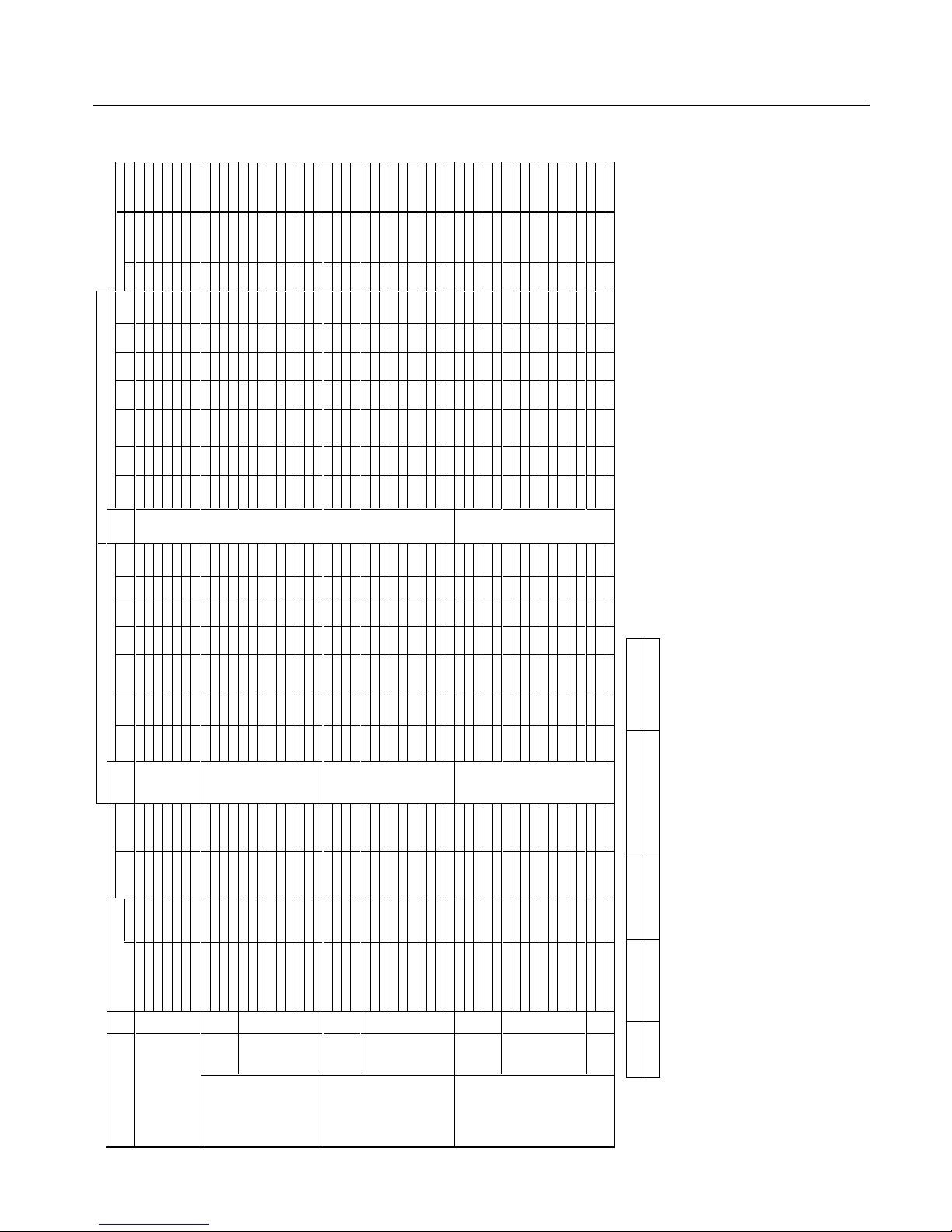
English-37
P50XP10 Supported Resolutions (Video)
Specification of the signal
Sig. t
c
e
l
e
s
D
H
R
E
D
N
U
1
:
5
3
.
29:4
1
M
O
O
Z
C
I
MA
N
Y
DLLU
F
LA
M
R
ON
T
U
P
N
I
RE
D
N
U1
:
53.
2
9
:
41
M
O
O
Z
C
I
M
A
N
Y
DL
L
U
FL
A
MR
O
N
TUP
N
I.
q
er
f
H
.
qe
r
fVnoitu
l
oseR
no.
H X V Signal Type (Hz) (kHz) terminal (4:3) (16:9)
(non-linear)
SCAN terminal (4:3) (16:9)
(non-linear)
SCAN Gr. No. Item Item
Video 101 3.58NTSC 59.9 15.8
Video1
Yes Yes Yes Yes Yes Yes Yes *3 -- -- -- -- -- -- -- -- -- - -
Composite / S 102
4.43NTSC 59.9 15.8 Video2 Yes Yes Yes Yes Yes Yes Yes *3 -- -- -- -- -- -- -- -- -- - -
103 PAL
50 15.6
S-Video
Yes Yes Yes Yes Yes Yes Yes *3 -- -- -- -- -- -- -- -- -- - -
104 PAL60 -
-
-
-
---
--
--
---
-
-
---
-
3
*
s
e
Y
s
eYseY
s
e
Ys
e
Yse
Y
s
e
Y
8
.
5
1
9
.95
105
PAL-N -
---
-
-
-
----
--
-
--
-
-
-
-
3
*
s
e
Y
se
Ys
eY
se
Y
s
e
Y
s
e
Y
s
e
Y6.5
1
0
5
106 PAL-M -
-
-
-
---
----
---
--
-
--
-
3
*
s
e
Y
s
eYseY
s
eYseY
se
Y
s
eY
8
.
5
1
9.95
107 SECAM
-
-
-
---
-
--
--
--
-
-
-
----
3*s
e
Y
s
e
Ys
e
Ys
e
Ys
e
Y
s
eYs
eY
6
.5
10
5
Y,Pb(Cb),Pr(Cr) SD
111
480I 59.9 15.8 DVD/HD1
Yes Yes Yes Yes Yes Yes Yes *3 -- -- -- -- -- -- -- -- -- - -
112 576I
50 15.6
DVD/HD2
Yes Yes Yes Yes Yes Yes Yes *3 -- -- -- -- -- -- -- -- -- - -
113
480P
-
-
-
---
-
--
----
-
---
--
-
3*s
e
Y
s
e
Ys
e
Y
se
Y
s
e
Ys
eYs
e
Y
5
.
1
39
.
9
5
114 576P
50
31.3
Yes Yes Yes Yes Yes Yes Yes *3 -- -- -- -- -- -- -- -- -- - -
HD 11 5
720P -
-
-
---
-
--
-
----
-
--
--
-
3
*
se
Y
seY-
-
-
-
s
e
Y
s
e
Y
-
-5.73
0
5
116
720P ---
--
-
----
-
---
-
-
-
---
3
*
se
Y
s
eY-
-
-
-se
Ys
eY-
-
5406
117 1080I
-
-
-
---
-
---
---
--
--
--
-
3
*
se
Y
se
Y-
-
-
-
se
YseY--1.8205
118 1080I
--
-
--
-
---
-
-
--
-
-
--
---
3
*
se
Y
seY-
-
--s
eY
s
e
Y
-
-
8
.
3
3
0
6
119 1080P -
-
-
---
-
-
--
----
-
-
-
-
-
-
3
*
s
e
Y
s
eY-
-
-
-
s
eY
s
e
Y
-
-
3
.
6
5
0
5
120
1080P
---
---
--
-
-
-
---
-
-
-
---
3
*
se
Y
s
e
Y-
-
-
-s
e
Ys
e
Y
-
-5
.760
6
121 1080P
-
--
--
-
-
---
---
-
-
--
---
3
*
s
eYse
Y-
-
-
-
s
eY
s
e
Y
-
-
8.3303
122 1080P 24 27 -- Yes Yes -- -- Yes Yes *3 -- -- -- -- -- -- -- -- -- - -
123
1080P 25 28
-- Yes Yes -- -- Yes Yes *3 -- -- -- -- -- -- -- -- -- - -
RGB(Video signal) SD 131 480I *4 59.9 15.8 VGA Yes Yes Yes Yes Yes Yes Yes *3 -- -- -- -- -- -- -- -- -- - -
132
576I *4
50 15.6 RGBHV Yes Yes Yes Yes Yes Yes Yes *3 -- -- -- -- -- -- -- -- -- - -
133 480P 59.9 31.5
(SCART1-3)
Yes Yes Yes Yes Yes Yes Yes *3 -- -- -- -- -- -- -- 2 480P - -
134 576P 50 31.3 Yes Yes Yes Yes Yes Yes Yes *3 -- -- -- -- -- -- -- -- -- - -
HD
135
720P --
-
-
-
----
--
----
-
---
-
3
*
s
eYseY----se
Y
seY--5.7305
136 720P
-
---
-
-
-
----
--
-
--
-
--
-
3
*
s
e
Y
s
eY-
-
-
-
s
eYseY--5406
137
1080I -
-
-
-
---
--
--
---
-
-
---
-
3
*
se
Y
seY---
-s
eYs
e
Y
-
-1.82
0
5
138
1080I B080
1
--
-
------
--
--
-
-
---
3
*
se
Y
s
eY----seYseY--8.33
0
6
139
1080P
-
-
--
--
-
--
--
---
-
-
---
-
3
*
se
Y
seY-
-
-
-
s
e
Y
s
e
Y
-
-3.65
0
5
140 1080P
-
--
-
-
-
-
---
-
--
-
--
---
-
3
*
se
Y
s
eY-
-
-
-seYseY--5.
7
606
141 1080P -
-
-
-
---
----
--
-
--
-
--
-
3
*
se
Y
se
Y-
---seYseY--8.
3
303
142
1080P 24 27
-- Yes Yes -- -- Yes Yes *3 -- -- -- -- -- -- -- -- -- - -
143
1080P 25 28
-- Yes Yes -- -- Yes Yes *3 -- -- -- -- -- -- -- -- -- - -
144 1080A/540P RCA STB
A0
8
0
1
--
-
----
--
--
-
-
-
-
---
3*se
Y
s
e
Y--
-
-seYseY--
8
.3306
Digital SD
161 640 X 480P 59.9 / 60.0 31.5 / 31.5 - - - - - - - - - - - - - - DVI Yes *3 Yes *3 Yes *3 Yes *3 Yes *3 Yes *3 Yes *3 - - - - - -
(EIA/CEA-861)
162
720 (1440) X 480I 59.9 / 60.0 15.7 / 15.8 - - - - - - - - - - - - - -
(DVI-HD)
Yes Yes Yes Yes Yes Yes Yes *3 - - - - - -
163
720 X 480P 59.9 / 60.0 31.5 / 31.5 - - - - - - - - - - - - - - Yes Yes Yes Yes Yes Yes Yes *3 - - - - - -
164
720 (1440) X 576I
--
-
-
-
-
3
*
s
e
Y
se
Y
se
Y
s
e
Y
s
e
Ys
eYs
e
Y
-
--
--
-
-
----
-
-
-6.5105
165 720 X 576P
--
-
-
--
3*se
Y
s
eYs
e
Y
s
e
Y
s
e
Yse
Y
s
e
Y
-
--
-
----------3.1305
HD 166 1280 X 720P 59.9 / 60.0 45.0 / 45.0 -- -- -- -- -- -- -- -- Yes Yes -- -- Yes Yes *3 -- -- - -
167 1920 X 1080I 59.9 / 60.0 33.7 / 33.8 - - - - - - - - - - - - - - - - Yes Yes - - - - Yes Yes *3 - - - - - -
168 1920 X 1080P 59.9 / 60.0 67.4 / 67.5 -- -- -- -- -- -- -- -- Yes Yes -- -- Yes Yes *3 -- -- - -
169 1280 X 720P -
-
-
-
--
3*s
eY
s
eY-
---s
e
Ys
e
Y
-
--
--
--
-
---
--
-
-
-5.
7
3
0
5
170 1920 X 1080I -
---
-
-
3*s
e
Y
seY-
--
-
se
Yse
Y
--
-
--
--
-
---
--
---1.
8
2
0
5
171
1920 X 1080P --
--
-
-3
*
s
e
Y
s
e
Y---
-
s
e
Ys
e
Y
-
--
--
--
-
-
--
-
----
3
.6505
172
1920 X 1080P
-
---
-
-3*se
Y
seY--
--
seYs
e
Y---
-
---
----
--
-
-
-8.
3
3
0
3
173 1920 X 1080P 24 27 -- -- -- -- -- -- -- -- Yes Yes -- -- Yes Yes *3 -- -- - -
174 1920 X 1080P 25 28
-- -- -- -- -- -- -- -- Yes Yes -- -- Yes Yes *3 -- -- - -
Native 191 1366 X 768 -
-
-
--
--
-
-
--
--
-
-
-
3*
seY
-
---
-
-------
----3.7406
Resolution 192 1024 X 768
-
-----
-
---------3*seY----------------3.7406
193
853 X 480
60 30
-- -- -- -- -- -- -- -- Yes *3 -- -- -- -- -- -- -- - -
SIZE SIZE
RGB select
A
na
l
o
g
Digi
t
a
l
- - NOR MAL (4:3 ) FULL (16: 9) (*3 ) (*4)
Not Suppor ted 1024 pixels x 768 lin es 1365 pixel s x 768 lines Display ed by Underscan m ode (100%) SCART in put available
Page 41
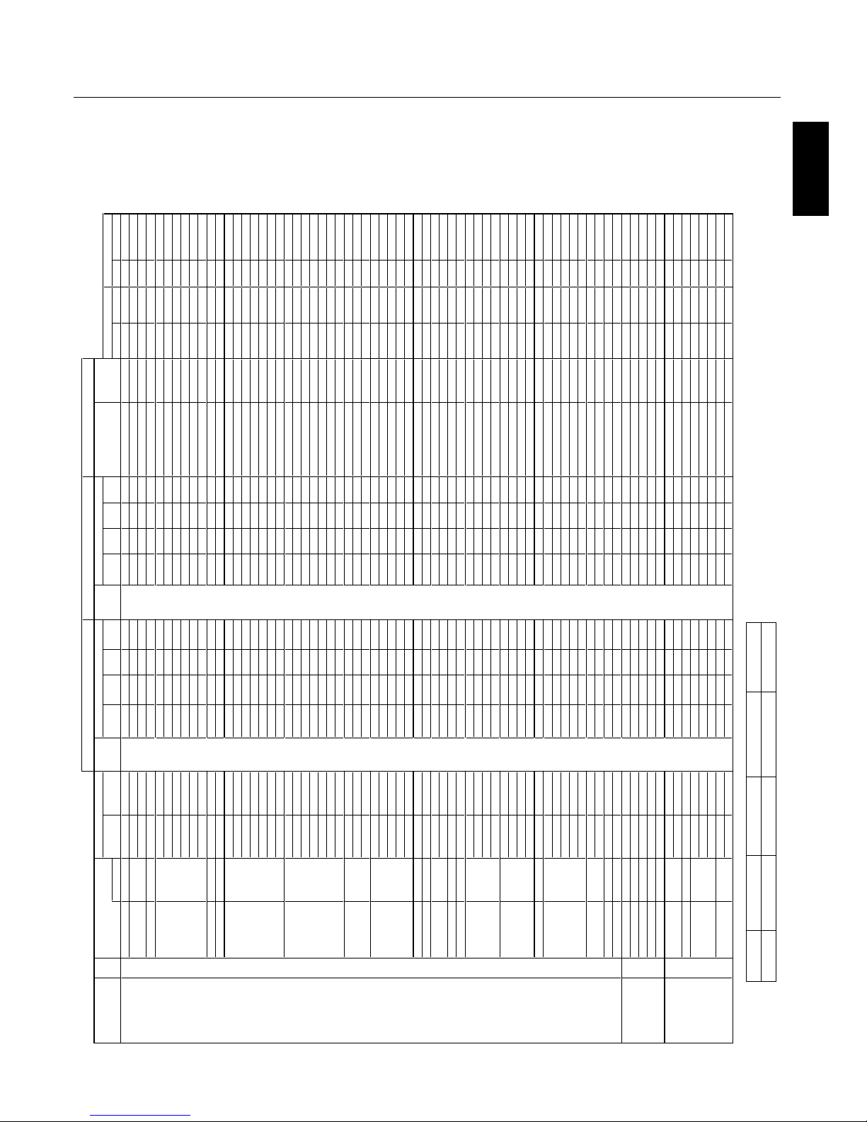
English
English-38
P60XP10 Supported Resolutions (PC)
Specification of the signal
Sig.
E
URT
M
O
OZL
L
UF
L
A
MR
O
NT
U
PN
IE
U
R
TM
O
OZ
L
LU
F
LA
M
R
ON
TU
PNI
.
q
erf
H
.
q
e
r
f
VnoituloseR
no. metI.
o
N
.
r
G
V
H)LA
E
R
(
)9:
6
1
(
)
3
:
4
(
l
a
n
im
ret
)
LA
E
R
()9:6
1
()
3
:
4
(
l
an
im
ret)
z
H
k
(
)
Z
H
(e
p
y
T
l
a
ngi
SH X V
IBM PC/AT
1
640 X 400 400line 70.1 31.5 VGA
-- Yes -- - -
DVI
-- -- -- - -
Yes Yes
Neg. Neg. 1 640X400
Compatible 2 720 X 400 400line 70.1 31.5 RGBHV
-- Yes -- Yes
(DVI-PC)
-- Yes -- Yes
Yes Yes
Neg. Neg. 1 720X400
Computers s
e
Y--s
eY--
s
e
Y
-
-
s
e
Y
--9
.
7
3
5
8
3 Yes Yes
Neg. Pos. - - - -
4 720 X 350 350line 70.1 31.5 - - Yes - - Yes - - Yes - - Yes Yes Yes Neg. Neg. 1 720X350
5 640 X 480 VGA
59.9 31.5 Yes Yes Yes Yes Yes Yes Yes Yes
Yes Yes
Neg. Neg. 2 640X480
se
Y
s
e
Y
s
eYs
eY
se
Y
s
eYs
e
Y
s
e
Y
9.738.
27
6 Yes Yes Neg. Neg. - - - -
se
Y
s
eYse
Y
s
eY
se
Yse
Ys
e
Y
s
e
Y
5.7
3
577
Yes Yes
Neg. Neg. - - - -
se
Y
s
eYse
Y
s
e
Y
s
e
Y
s
e
Ys
e
Y
s
e
Y3.3
4
588
Yes Yes
Neg. Neg. - - - -
se
Y
s
eYse
Y
s
e
Y
s
e
Y
s
e
Ys
e
Y
s
e
Y
1
.1
5
4.0019
Yes Yes
Neg. Neg. - - - -
s
e
Y
s
e
Y
s
eY
s
e
Ys
eYs
e
Ys
e
Y
s
e
Y
3.164.02101
Yes Yes
Neg. Neg. - - - -
11 848 X 480 Wide-VGA s
eY-
-s
e
Y
--
s
eY
-
-
s
eY--13
0
6
Yes Yes
Pos. Pos. 2 848X480
12
852 X 480 Wide-VGA
60 31.7 - - Yes - - Yes - - Yes - - Yes
Yes Yes
Neg. Neg. 2 852X480
13 800 X 600 SVGA 56.3 35.2 Yes Yes Yes Yes Yes Yes Yes Yes
Yes Yes
Pos. Pos. - - - -
s
e
Y
s
e
Y
s
e
Y
se
Ys
e
Ys
eY
s
eYseY9.733.0641 Yes Yes Pos. Pos. - - - -
s
e
Y
s
eYse
Y
se
Ys
e
Y
s
e
Y
s
e
Y
seY
1
.842.
2
751
Yes Yes
Pos. Pos. - - - -
se
Y
s
e
Y
se
Y
s
eY
se
Yse
Ys
e
Y
s
e
Y9.6
4
5761 Yes Yes Pos. Pos. - - - -
s
e
Y
s
e
Y
s
e
Y
s
e
Ys
eYs
eYse
Y
s
e
Y7
.
3
5
1
.
5
871
Yes Yes
Pos. Pos. - - - -
s
eYse
Y
s
e
Y
s
e
Ys
eY
s
e
Y
se
Y
s
e
Y
36
8
.
9
9
8
1 Yes Ye s Pos. Pos. - - - -
se
Y
s
e
Y
s
e
Yse
Ys
eYs
eY
seYse
Y
7.5702191
Yes Yes Pos. Pos. - - - -
20 1024 X 768 XGA 60 48.4 Yes Yes Yes - - Yes Yes Yes - -
Yes Yes Neg. Neg. 3 1024X768
-
-
s
eYse
Y
s
e
Y
--se
Y
s
eYseY
5
.651
.07
12 Yes Yes Neg. Neg. 5 1024X768
--s
eYse
Y
s
e
Y
-
-
se
Y
s
eYseY9.759
.17
22
Yes Yes
Neg. Neg.
6 1024X768
--
s
e
Y
s
eYs
eY
--
seYse
Y
seY065
7
32 Yes Yes Pos. Pos. - - - -
--
s
e
Y
s
e
Ys
eY--seYse
Y
se
Y
7
.86
5
8
42
Yes Yes
Pos. Pos. - - - -
-
-
s
e
Y
s
e
Y
s
e
Y--se
Y
se
Y
se
Y5.086
.001
52 Yes - -
Neg. Neg. - - - -
-
-
s
e
Y
s
e
Y
s
eY--seYseYseY5.594.91162 Yes - -
Neg. Neg. - - - -
27 1152 X 864 XGA 60 53.7 Yes Yes Yes - - Yes Yes Yes - -
Yes Yes
Pos. Neg. - - - -
--s
eYse
Y
s
eY
--
s
eYse
Y
se
Y9.46
2
7
82
Yes Yes
Pos. Neg. - - - -
--
s
e
Y
s
e
Ys
eY--se
Y
seYse
Y
5
.7
6
57
92
Yes Yes
Pos. Pos. - - - -
30
1280 X 768 Wide-XGA 56.2 45.1 - - Yes - - - - - - - - - - - -
Yes Yes
Pos. Pos. - - - -
---
-s
e
Y
--
-
--
-
seY--84
8
.9513 Yes Yes
Pos. Neg. 3 1280X768-1
---
-s
e
Y
-
-
--
-
-seY--
8
.74
9
.952
3 Yes Ye s
Neg. Pos. 3 1280X768-2
-
--
-s
eY
--
-
--
-
seY-
-
6
58
.9633 Yes Yes
Neg. Pos. 5 1280X768
-
--
-seY-
-----seY--8.752743 Yes Ye s Neg. Pos. 6 1280X768
35 1280 X 800 Wide-XGA
59.8 49.7 -- Yes -- -- -- Yes -- - - Yes Yes
Neg. Pos. 4 1280X800
36 1280 X 854 Wide-XGA 60 53.1 - - Yes - - - - - - Yes - - - - Ye s Ye s
Neg. Neg. - - - -
37 1280 X 960 Wide-XGA 60 60 Yes Yes Yes - - Yes Yes Yes - -
Yes Yes
Pos. Pos. - - - -
--se
Y
seY
s
eY--2*seY2*
s
eY2*seY9.58588
3
Yes - - Pos. Pos. - - - -
39 1360 X 768 Wide-XGA 60 47.7 -- Yes -- -- -- Yes -- - -
Yes Yes
Pos. Pos. 3 1360X768
40 1376 X 768 Wide-XGA 59.9 48.3 - - Yes - - - - - - Yes - - - -
Yes Yes
Neg. Pos. 3 1376X768
41 1280 X 1024 SXGA 60 64 Yes *1 Yes Yes - - Yes *1 Yes Yes - - Ye s Ye s Pos. Pos. 9 1280X1024
--seYseY1*
s
eY
--seYse
Y
1*s
e
Y085724 Yes - -
Pos. Pos. - - - -
-
-
seYseY1*
se
Y
-
-
2
*
s
e
Y
2
*
s
e
Y
2
*
1*se
Y1.19
58
34 Yes - - Pos. Pos. - - - -
-
--
--
----
-
2*seY
2
*
s
e
Y
2*1*se
Y
5
.8011.00
1
4
4
Yes - -
Pos. Pos. - - - -
45 1400 X 1050 SXGA+ 60 64 Yes Yes Yes - - Yes Yes Yes - -
Yes - -
Neg. Pos. 9 1400X1050
--se
Y
seYseY--seYseYseY3.56066
4
Yes - -
Neg. Pos.
7 1400X1050
--seYseYseY-
-
2*seY
2
*
s
e
Y
2*
se
Y3
.28
9.4774 Yes - - Neg. Pos. - - - -
-
----
-
----2*seY2*seY
2*seY9.395884 Yes - -
Neg. Pos. - - - -
49
1680 X 1050 Wide-SXGA
60 65.3 - - Yes - - - - - - Yes - - - - Ye s - -
Neg. Pos. 7 1680X1050
50 1600 X 1200 UXGA 60 75 Yes *2 Yes *2 Yes *2 - - Yes Yes Yes - - Yes - -
Pos. Pos. 8 1600X1200
-
-----
-
-
-
-
2
*
s
e
Y
2
*
s
e
Y
2*s
eY3.
1
8
5
615 Yes - - Pos. Pos. - - - -
-
----
--
-
-
-
2
*
s
e
Y
2
*
s
e
Y
2*
seY5
.
7
8
0
7
25 Yes - -
Pos. Pos. - - - -
--
--
--
-
-
--2*s
e
Y2*
s
eY2*s
e
Y
8.
3
9
5
7
35
Yes - -
Pos. Pos. - - - -
-
---
-
-----2*seY2*seY2*seY3.60158
4
5
Yes - -
Pos. Pos. - - - -
55 1920 X 1080 50 56.2 - - - - - - - - - - Yes - - - - Yes - - Pos. Pos. - - - -
---
-s
eY-
-
--
------5
.
7
60
665
Yes - -
Pos. Pos. - - - -
57
1920 X 1200 Wide-UXGA
59.9 74.6 -- Yes *2 -- -- -- -- -- - -
Yes - -
Neg. Pos. 8 1920X1200
58 1920 X 1200RB Wide-UXGA ----seY----
-
-2*seY--
4
706 Yes - -
Neg. Pos. - - - -
Apple Macintosh® 81
640 X 480 Mac13"
66.7 35 Yes Yes Yes -- -- -- -- - - Yes Yes
Sync on G Sync on G - - - -
82 832 X 624 Mac16"
74.6 49.7 Yes Yes Yes - - - - - - - - - -
Yes Yes
Sync on G Sync on G - - - -
83 1024 X 768 Mac19" 74.9 60.2 Yes Yes Yes - - - - - - - - - -
Yes Yes Sync on G Sync on G - - - -
84 1152 X 870 Mac21" 75.1 68.7 Yes Yes Yes - - - - - - - - - - Ye s Yes Sync on G Sync on G - - - -
85 1440 X 900 Apple17 59.9 55.9 - - Yes - - - - - - Yes - - - - Yes Yes Neg. Pos. - - - -
EWS Series 91
Work Station EWS4800
60 64.6 Yes *1 Yes Yes - - Yes *1 Yes Yes - -
Yes - - Neg. Neg. - - - -
92
1280 X 1024
71.2 75.1 Yes *1 Yes Yes - - Yes *1 Yes Yes - - Yes - - Neg. Neg. - - - -
93
1280 X 1024 HP
72 78.1 Yes *1 Yes Yes - - Yes *1 Yes Yes - - Ye s - - - - - - - -
94 1152 X 900 SUN 66 61.8 Yes Yes Yes - - Yes Yes Yes - -
Yes Yes
C Sync C Sync - - - -
95 1152 X 900 76 71.7 Yes Yes Yes - - Yes Yes Yes - - Yes Yes
C Sync C Sync - - - -
96
1280 X 1024
76.1 81.1 Yes *1 Yes Yes - - Yes *1 Yes Yes - - Yes - -
C Sync C Sync - - - -
97
1024 X 768 SGI
60 49.7 Yes Yes Yes - - Yes Yes Yes - - Yes - -
- - 4 1024X768
98 1280 X 1024 60 63.9 Yes *1 Yes Yes - - Yes *1 Yes Yes - - Yes - -
- - - - - -
l
atig
iDgol
an
A
TEXT INSERT
t
c
e
l
e
s
B
GR
y
t
ir
a
l
o
p
c
n
y
S
E
ZI
SE
ZI
S
TOP1-3/MID HIGH/
MID LOW/BOTTOM1-3
Left/Right
- - NOR MAL (4:3 ) FULL (16: 9) (*1) ( *2)
Not Suppor ted 1024 pixels x 768 lin es 1366 pixel s x 768 lines Aspect r atio is 5:4 ( 960x768) Ro ugh Sampling
Page 42
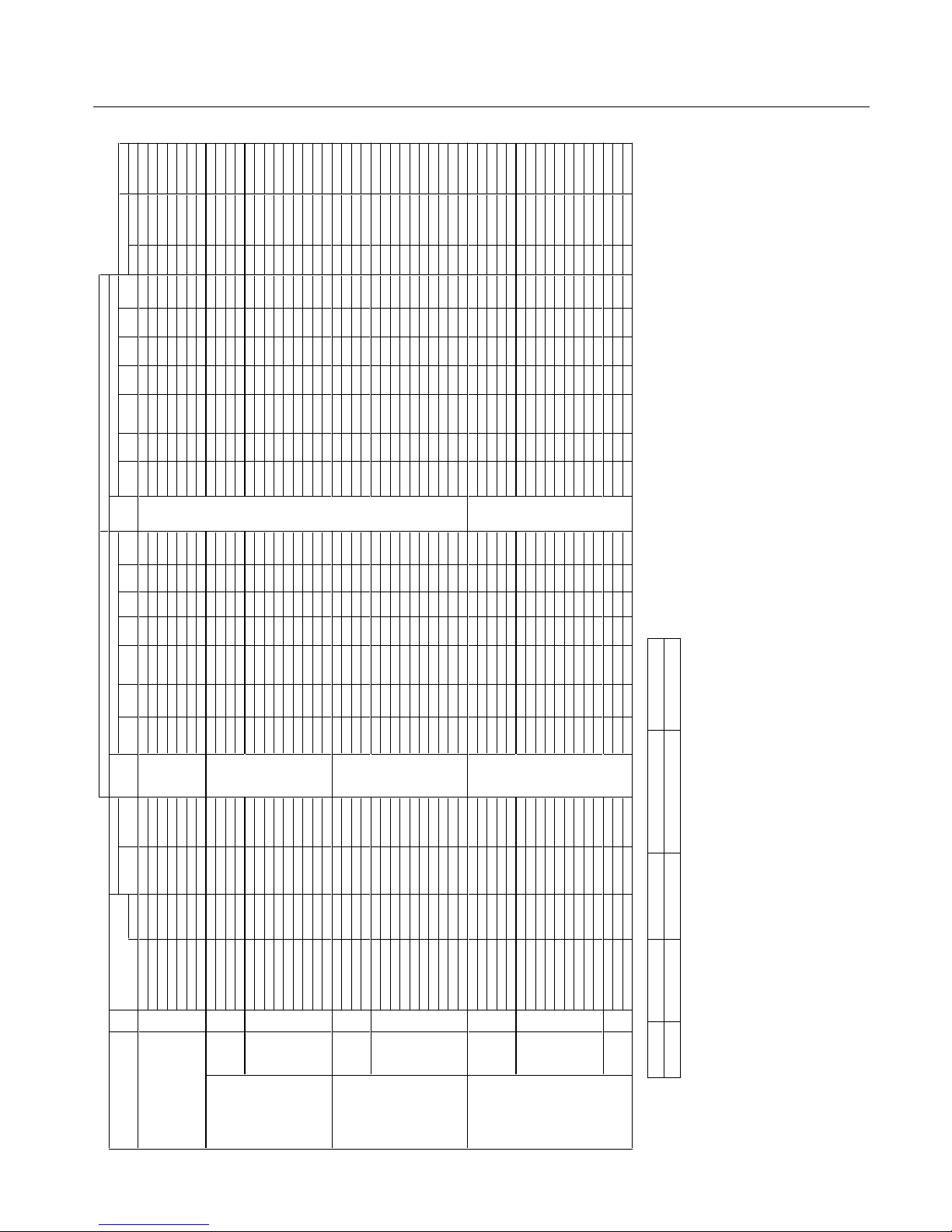
English-39
P60XP10 Supported Resolutions (Video)
Specification of the signal
Sig. t
c
e
l
e
s
D
H
R
ED
NU
1
:
5
3
.
2
9:4
1
MO
O
ZCI
M
ANYDL
L
U
FL
A
MR
O
N
T
U
PNIREDN
U
1:5
3
.
2
9:4
1
M
OO
Z
C
I
M
A
NY
D
L
L
U
F
L
A
M
R
ON
T
U
P
N
I
.
q
e
r
f
H
.
qe
rf
V
n
o
i
t
u
l
o
s
e
R
no.
H X V Signal Type (Hz) (kHz) terminal (4:3) (16:9)
(non-linear)
SCAN terminal (4:3) (16:9)
(non-linear)
SCAN Gr. No. Item Item
Video
101 3.58NTSC 59.9 15.8
Video1
Yes Yes Yes Yes Yes Yes Yes *3 -- -- -- -- -- -- -- -- -- - -
Composite / S 102 4.43NTSC
59.9 15.8
Video2
Yes Yes Yes Yes Yes Yes Yes *3 -- -- -- -- -- -- -- -- -- - -
103 PAL
50 15.6 S-Video Yes Yes Yes Yes Yes Yes Yes *3 -- -- -- -- -- -- -- -- -- - -
104 PAL60
-
---
-
----
-
-
-
-
-
-
--
-
-
-
3
*s
eYse
Y
s
eY
s
eYs
e
Y
s
eY
s
e
Y
8
.
519
.
95
105
PAL-N
-
--
-
-
-
-
-
-
-
-
----
--
-
-
-
3*se
Y
s
e
Y
s
eY
s
eYs
e
Ys
e
Y
seY
6
.
5
1
05
106 PAL-M -
---
-
----
-
-
-
-
-
-
-
-
-
--3*s
e
Y
se
Y
s
eY
se
Y
se
Y
s
e
Y
s
e
Y8
.
5
19.
9
5
107 SECAM
-
-
---
-
-
-
-
-
-
-
-
--
--
-
--3*s
e
Y
s
eYs
e
Y
s
eYs
e
Ys
eY
s
e
Y
6.
5
10
5
Y,Pb(Cb),Pr(Cr) SD
111
480I 59.9 15.8
DVD/HD1
Yes Yes Yes Yes Yes Yes Yes *3 -- -- -- -- -- -- -- -- -- - -
112 576I 50 15.6 DVD/HD2 Yes Yes Yes Yes Yes Yes Yes *3 -- -- -- -- -- -- -- -- -- - -
113
480P -
---
-
----
-
-
-
-
-
-
--
-
--3*seYse
Y
s
e
Y
s
eYs
e
Y
s
eY
s
eY
5
.
139.95
114 576P
-
-
-
-
-
-
-
--
-
-
-
-
-
-
--
-
-
-
3*s
eY
s
e
Y
s
eY
s
e
Y
s
e
Ys
eY
s
eY3.
1
30
5
HD 115 720P ---
-
---
-
-
-
-
-
-
-
------3*se
Y
seY
-
--
-
se
Ys
e
Y
-
-
5
.73
0
5
116 720P --------
--
-
-
-
-
-
-
--
-
-3
*
se
Y
s
e
Y
-
-
-
-
se
Ys
e
Y
-
-5406
117
1080I
-
-
-
-
-
-
-
-
-
-
-
-
-
----
-
--3*s
e
Y
s
eY--
-
-
s
e
Y
se
Y
--1.
8
20
5
118 1080I
---
-
---
--
-
-
-
-
-
-
---
-
-
3
*
seYseY--
-
-
s
e
Ys
e
Y
-
-
8
.3306
119
1080P
-
--
-
-
-
-
-
-----
--
--
--
-
3*se
Y
s
eY-
--
-
se
Ys
e
Y
-
-3.
6
50
5
120
1080P
---
-
---
-
-
-
---
-------3*se
Y
se
Y
--
-
-
s
e
Y
s
e
Y
--5.7606
121
1080P
-
--
-
-
--
-----
-
-
-
--
---3*se
Y
s
e
Y
-
-
-
-
s
e
Y
se
Y
--
8.
3
30
3
122 1080P
-
---
-
-
-
-------
-
-
-
-
-
-
3
*
seYseY--
-
-
se
Ys
e
Y
-
-7242
123
1080P -
--
--
-
-
-
-
-------
-
-
-
-
3
*
s
e
Y
s
e
Y
-
-
-
-
s
eY
s
eY
-
-8
2
5
2
RGB(Video signal) SD
131 480I *4 59.9 15.8
VGA
Yes Yes Yes Yes Yes Yes Yes *3 -- -- -- -- -- -- -- -- -- - -
132 576I *4 50 15.6 RGBHV Yes Yes Yes Yes Yes Yes Yes *3 -- -- -- -- -- -- -- -- -- - -
133 480P
59.9 31.5 (SCART1-3) Yes Yes Yes Yes Yes Yes Yes *3 -- -- -- -- -- -- -- 2 480P - -
134 576P
-
-
-
-
-
-
-
--
-
-
--
-
-
--
-
-
-
3*s
e
Y
s
e
Y
s
eY
se
Y
seYseYseY3.1305
HD 135 720P ---
-
---
-
-
-
-
-
-
-
-
-
----3*se
Y
seY
-
-
-
-
s
e
Y
se
Y
--5
.
7
3
05
136 720P --------
--
-
-
-
-
-
-
--
-
-3
*
se
Y
s
e
Y
-
-
-
-
se
Ys
e
Y--5406
137
1080I -
--
--
-
-
-
-------
--
-
--
3
*
se
Y
s
eY-
-
--s
e
Ys
e
Y
--1
.
8
20
5
138 1080I B
0
8
01------
-
-
-
-
-
-
-
-----3*se
Y
seY
--
-
-s
e
Y
se
Y
--8
.
3
3
06
139
1080P --
-
-----
---
-
-
-
-
---
-
-
3*s
e
Y
seY-
--
-
s
e
Ys
e
Y
-
-
3
.
6
5
05
140 1080P ---
--
-
-
-
-------
----
-
3*se
Y
se
Y
----s
e
Ys
e
Y-
-
5.
7
60
6
141
1080P
--------
-
-
-
-
-
-
-
-----3*se
Y
seY--
-
-
s
e
Ys
e
Y
--8.3
3
03
142
1080P
--------
-
-
-
-
-
-
-
-
-
-
-
-3
*s
eYs
e
Y
-
---s
e
Ys
e
Y
-
-7242
143
1080P
-
--
--
-
-
--
--------
-
-
-
3
*s
eYs
eY
-
--
-
s
eY
s
eY-
-8
2
5
2
144 1080A/540P RCA STB
A
0
80
1
-
-
-
----
----
-
-
--
-
-
-
3*s
e
Y
s
e
Y-
--
-s
e
Ys
e
Y
--8
.
3
3
0
6
Digital SD 161
640 X 480P
59.9 / 60.0 31.5 / 31.5 - - - - - - - - - - - - - - DVI Yes *3 Yes *3 Yes *3 Yes *3 Yes *3 Yes *3 Yes *3 - - - - - -
(EIA/CEA-861) 162 720 (1440) X 480I 59.9 / 60.0 15.7 / 15.8 - - - - - - - - - - - - - -
(DVI-HD)
Yes Yes Yes Yes Yes Yes Yes *3 - - - - - -
163
720 X 480P
59.9 / 60.0 31.5 / 31.5 - - - - - - - - - - - - - - Yes Yes Yes Yes Yes Yes Yes *3 - - - - - -
164 720 (1440) X 576I -
-
-
-
-
-3*s
e
Ys
eYs
e
Y
se
Y
se
Y
se
Y
s
e
Y
-
-
-
-----
-
-----6.
5
105
165
720 X 576P
------3*se
Yse
Ys
eY
se
Y
s
e
Y
se
Y
s
eY-
-
-
--
--
-
-
--
---3
.
1
3
05
HD
166
1280 X 720P 59.9 / 60.0 45.0 / 45.0 -- -- -- -- -- -- -- -- Yes Yes -- -- Yes Yes *3 -- -- - -
167
1920 X 1080I
59.9 / 60.0 33.7 / 33.8 - - - - - - - - - - - - - - - - Yes Yes - - - - Yes Yes *3 - - - - - -
168 1920 X 1080P
59.9 / 60.0 67.4 / 67.5 - - - - - - - - - - - - - - - - Yes Yes - - - - Yes Yes *3 - - - - - -
169 1280 X 720P
-
---
-
-3*s
eY
s
e
Y----se
Y
seY-----------
--
---5
.
7
3
05
170 1920 X 1080I
-
--
-
-
-
3
*s
e
Y
s
e
Y-
-
-
-
s
e
Y
s
e
Y--
-
-
-
--
--
----
--
-
1
.82
0
5
171 1920 X 1080P
-
--
--
-3*se
Ys
eY----se
Y
seY-------------
--
-3.6505
172
1920 X 1080P
-
---
-
-
3
*
s
eY
s
e
Y----s
e
Y
se
Y
-
-
-
-
-
--
---
-
----
-
8.
3
30
3
173 1920 X 1080P
-
--
-
-
-
3*s
e
Y
s
e
Y-
-
-
-se
Y
s
e
Y-------
-
-----
-
--7
2
4
2
174 1920 X 1080P ------
3
*
se
YseY-
-
-
-
se
Y
s
e
Y-
---
-
------
-----8252
Native 191 1366 X 768 ---
-
---
-
-
-
-
-
-
-
--3*seY
-
-
-
-
-
-----
-
----
-
3
.74
06
Resolution 192
1024 X 768
-
--
-
-
-
-
------
-
-
-
3*se
Y
--------
-
-
-
----
-
3
.74
06
193 853 X 480
-
-
-
-
-
-
-
---
-
-
-
-
--
3*se
Y
----
-
--
-
---
-
---
-03
06
SIZE SIZE
RGB select
A
na
l
o
g
Digi
ta
l
- - NOR MAL (4:3 ) FULL (16: 9) (*3 ) (*4)
Not Suppor ted 1024 pixels x 768 lin es 1366 pixel s x 768 lines Display ed by Underscan m ode (100%) SCART in put available
Page 43
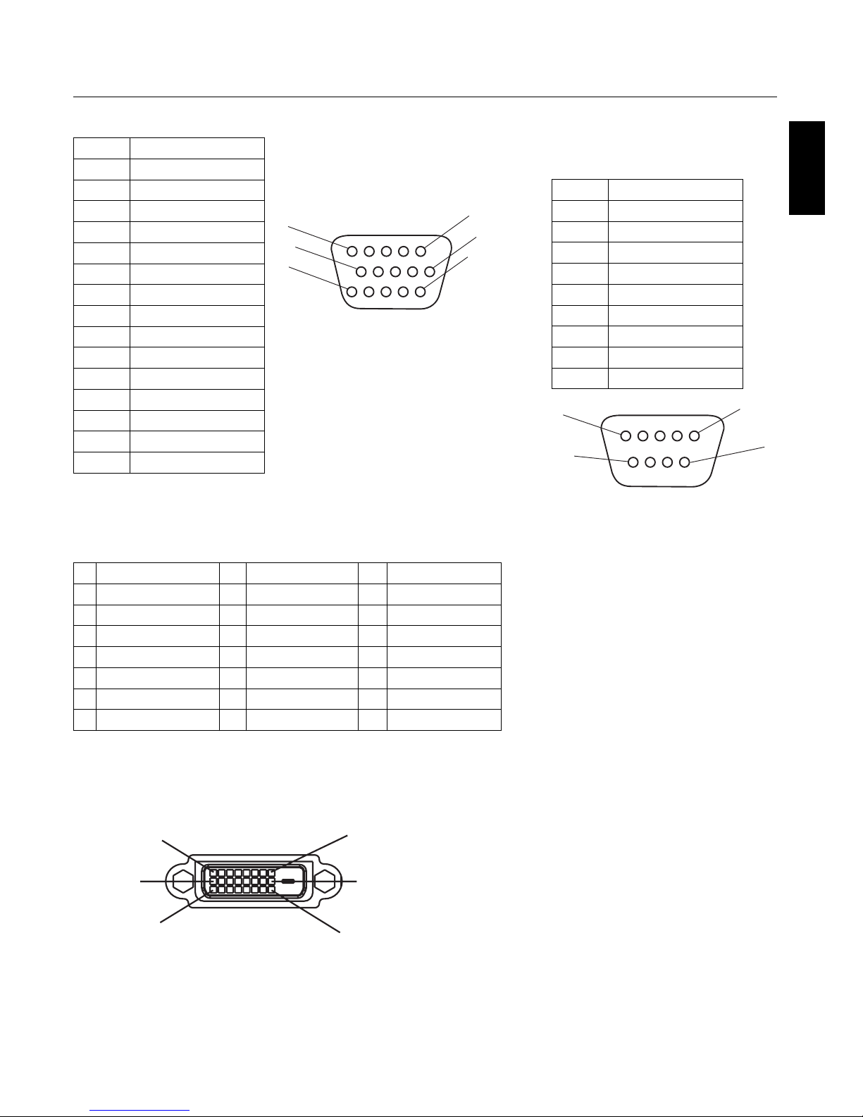
English
English-40
Pin Assignment
1) Analog RGB Input (Mini D-SUB 15P) VGA
Pin No. Name
1 Video Signal Red
2 Video Signal Green
3 Video Signal Blue
4 GND
5 DDC-GND
6 Red-GND
7 Green-GND
8 Blue-GND
9 +5V (DDC)
10 SYNC-GND
11 GND
12 DDC-SDA
13 H-SYNC
14 V-SYNC
15 DDC-SCL
2) Digital RGB Input (DVI-D) DVI
1 TX2- 9 TX1- 17 TX0-
2 TX2+ 10 TX1+ 18 TX0+
3 Shield (TX2/TX4) 11 Shield (TX1/TX3) 19 Shield (TXP/TX5)
4NC 12NC 20NC
5NC 13NC 21NC
6 DDC-Serial Clock 14 +5 power 22 Shield (TXC)
7 DDC-Serial Data 15 Ground (+5V) 23 TXC+
8 NC 16 Hot Plug Detect 24 TXC-
1
6
11
15
10
5
1
9
17
8
16
24
3) RS-232C Input
(D-SUB 9P)
Pin No. Name
1 Connected to 7 & 8
2 RXD
3 TXD
4 Connected to 6
5 GND
6 Connected to 4
7 Connected to 1 & 8
8 Connected to 1 & 7
9NC
5
9
6
1
D-SUB 9P
DVI-D
Mini D-SUB 15P
Page 44
DECLARATION OF CONFORMITY
is device complies with Part 15 of FCC Rules. Operation is subject to the following two
conditions. (1) is device may not cause harmful interference, and (2) this device must accept
any interference received, including interference that may cause undesired operation.
U.S. Responsible Party: NEC Display Solutions of America, Inc.
Address: 500 Park Blvd. Suite 1100
Itasca, IL 60143
Tel. No.: (630)467-3000
Type of Product: Computer Monitor
Equipment Classi cation: Class B Peripheral
Model: PlasmaSync 42XP10 (P426Y0)
PlasmaSync 50XP10 (P506Y1)
PlasmaSync 60XP10 (P606Y2)
We hereby declare that the equipment speci ed above
conforms to the technical standards as speci ed in the FCC Rules.
Windows is a registered trademark of Microso Corporation. NEC is a registered trademark of
NEC Corporation. All other brands and product names are trademarks or registered trademarks
of their respective owners.
Declaration of the Manufacturer
We hereby certify that the color monitor
P426Y0, P506Y1 or P606Y2 is in compliance
with Council Directive 73/23/EEC:
– EN 60950-1
Council Directive 89/336/EEC:
— EN 55022
— EN 61000-3-2
— EN 61000-3-3
— EN 55024
and marked with
NEC Display Solutions Ltd.
4-13-23, Shibaura,
Minato-Ku
Tokyo 108-0023, Japan
WEEE Mark (European Directive 2002/96/EC)
Within the European Union
EU-wide legislation, as implemented in each Member State, requires that waste electrical and electronic products
carrying the mark (le ) must be disposed of separately from normal household waste. is includes monitors and
electrical accessories, such as signal cables or power cords. When you need to dispose of your NEC display products,
please follow the guidance of your local authority, or ask the shop where you purchased the product, or if applicable,
follow any agreements made between yourself and NEC. e mark on electrical and electronic products only applies
to the current European Union Member States.
e mark on electrical and electronic products only applies to the current European Union Member States.
Outside the European Union
If you wish to dispose of used electrical and electronic products outside the European Union, please contact your
local authority so as to comply with the correct disposal method.
 Loading...