

Page 1
INSTALLATION INSTRUCTIONS
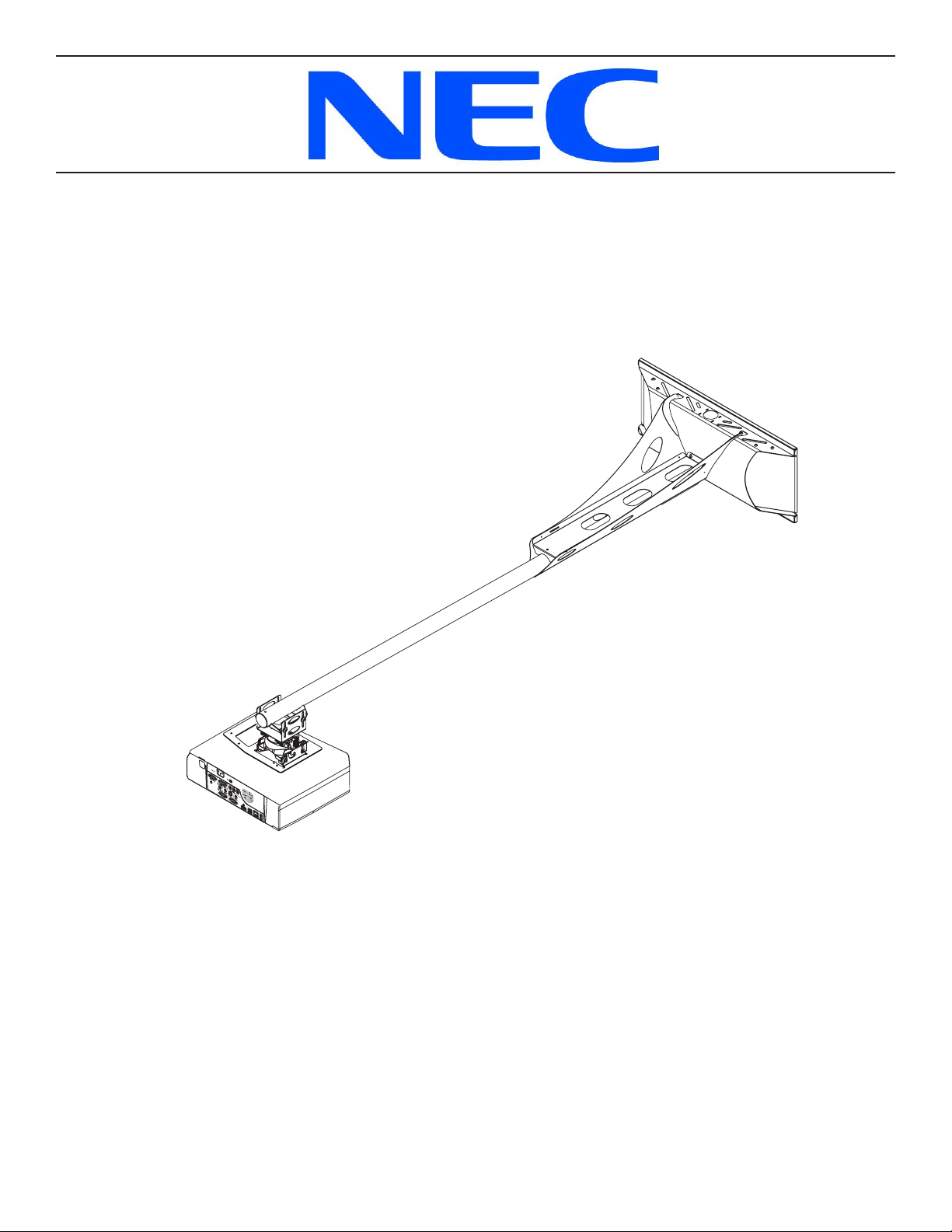
Short Throw Projector Arm
Model: NPLTWM
Page 2
NPLTWM
Table of Contents
Weight Capacity ..................................................................................... . 2
Warning Statements .................................................................................. . 2
Installation Tools ..................................................................................... . 3
Parts List ........................................................................................... . 3
Projector Mount Features .............................................................................. . 5
Determining the Installation Height ....................................................................... . 6
Wood Stud Installation ................................................................................. . 7
Attaching the Projector Arm ............................................................................. . 8
Throw Distance Calculation ............................................................................. . 9
Attaching the Projector Mount ........................................................................... . 10
Extension Arm Installation (Optional) ..................................................................... . 11
Adjustable Mounting Bracket Installation. . . . . . . . . . . . . . . . . . . . . . . . . . . . . . . . . . . . . . . . . . . . . . . . . . . . . . . . . . . . . . . . . . . . 12
Attaching the Projector Bracket .......................................................................... . 13
Lock-It™ Security Hardware Pack. . . . . . . . . . . . . . . . . . . . . . . . . . . . . . . . . . . . . . . . . . . . . . . . . . . . . . . . . . . . . . . . . . . . . . . . . 13
Alignment & Fine-Tuning ............................................................................... . 15
Locking in the Adjustments ............................................................................. . 16
Utilizing the Storage Feature ............................................................................ . 16
Cable Management ................................................................................... . 17
Technical Specications ................................................................................ 18
Disclaimer .......................................................................................... . 19
Weight Capacity
Maximum projector weight:
Warning Statements
PRIOR TO THE INSTALLATION OF THIS PRODUCT, THE INSTALLATION INSTRUCTIONS SHOULD BE READ AND COMPLETELY UNDERSTOOD. THE INSTALLATION INSTRUCTIONS MUST BE READ TO PREVENT PERSONAL INJURY AND PROPERTY DAMAGE. KEEP
THESE INSTALLATION INSTRUCTIONS IN AN EASILY ACCESSIBLE LOCATION FOR FUTURE REFERENCE.
NEC DOES NOT WARRANT AGAINST DAMAGE CAUSED BY THE USE OF ANY NEC PRODUCT FOR PURPOSES OTHER THAN THOSE
FOR WHICH IT WAS DESIGNED OR DAMAGE CAUSED BY UNAUTHORIZED ATTACHMENTS OR MODIFICATIONS, AND IS NOT RESPONSIBLE FOR ANY DAMAGES, CLAIMS, DEMANDS, SUITS, ACTIONS OR CAUSES OF ACTION OF WHATEVER KIND RESULTING
FROM, ARISING OUT OF OR IN ANY MANNER RELATING TO ANY SUCH USE, ATTACHMENTS OR MODIFICATIONS.
SAFETY MEASURES MUST BE PRACTICED AT ALL TIMES DURING THE ASSEMBLY OF THIS PRODUCT. USE PROPER
SAFETY GEAR AND TOOLS FOR THE ASSEMBLY PROCEDURE TO PREVENT PERSONAL INJURY.
At least two qualied people should perform the assembly procedure. Injury and/or damage can result from dropping or mishandling the
projector.
If mounting to studs, make sure that the mounting screws are anchored into the center of the studs. Use of an edge-to-edge stud nder is
recommended.
Be aware of the mounting environment. If drilling and/or cutting into the mounting surface, always make sure that there are no electrical wires in
wall. Cutting/drilling into an electrical line may cause serious injury.
Make sure there are no water lines inside the wall where the mount is to be located. Cutting/drilling into a water line may cause severe water
damage to the mounting surface.
50 lb.
THE WALL STRUCTURE MUST BE CAPABLE OF HOLDING FIVE
(5) TIMES THE WEIGHT OF THE PROJECTOR. IF NOT, THEN THE
WALL STRUCTURE MUST BE REINFORCED.
This product is intended for indoor use only. Use of this product outdoors could lead to product failure and personal injury.
Do not install near sources of high heat. Do not install on a structure that is prone to vibration, movement or chance of impact
Contact NEC with any questions
(800) 368-9700
techsupport@mounts.com
Page 2
Installation Instructions
Page 3
NPLTWM
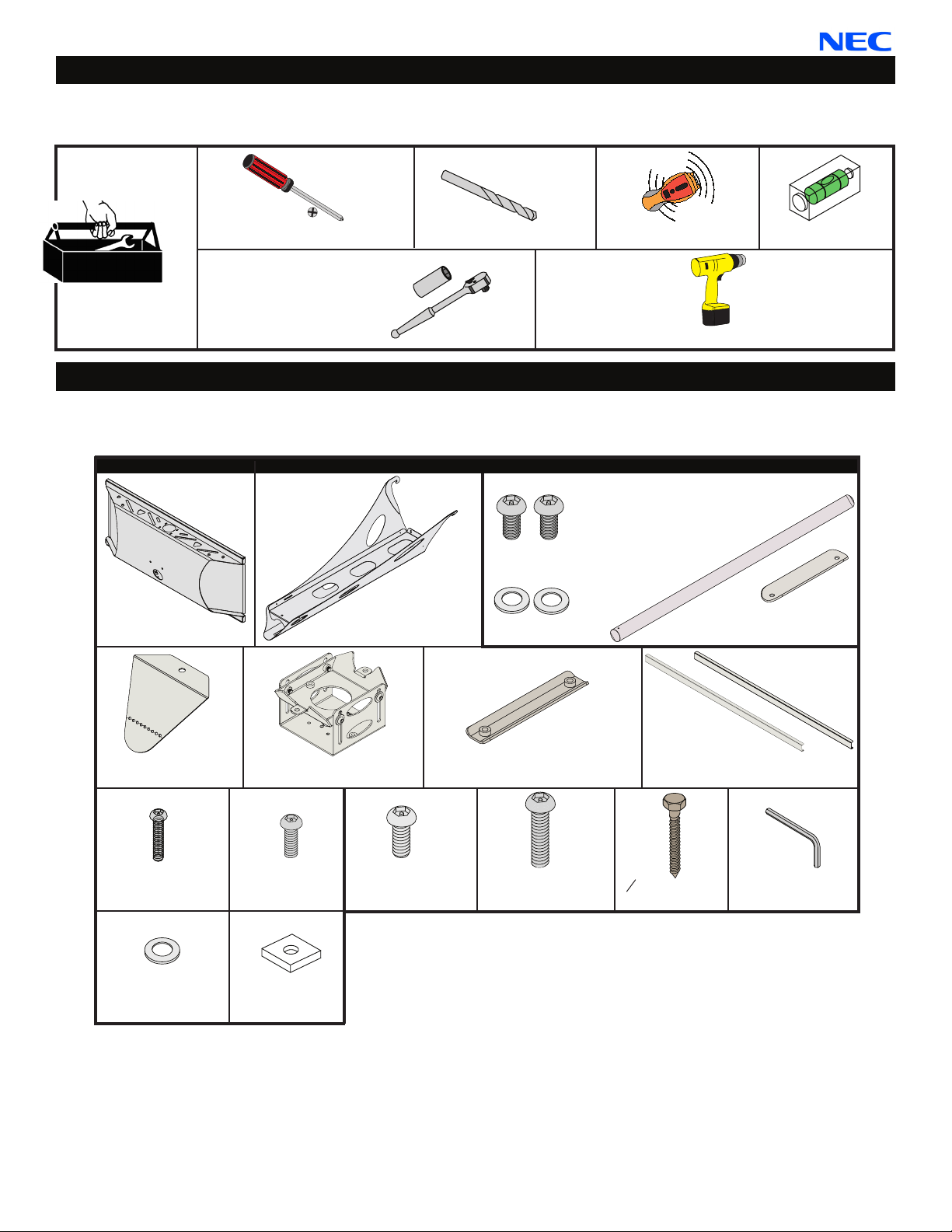
Installation Tools
The following tools may be required depending upon your particular installation. They are not included.
Phillips Screwdriver
½˝ Socket and Socket
Wrench
¼˝ Drill Bit
Electronic Stud Finder
Drill
Level
Parts List
Make sure your NEC product has the following hardware and components before beginning installation. If there are parts
missing and/or damaged, stop the installation and call NEC at (800) 368-9700.
Wall Plate
(Qty 1)
Projector Mount Hardware
Arm Assembly
(Qty 1)
Extension Hardware Pack
M6 x 12mm Security
Screws (pre-assembled)
(Qty 2)
M6 Flat Washer
(Qty 2)
Extension Arm - Optional (Qty 1)
External Slide Plate
(Qty 1)
End Cover
(Qty 1)
M4 x 10mm
Security Screws (Qty 4)
¼˝ Nylon Spacer
(Qty 2)
Installation Instructions
Adjustable Mounting Assembly
- Pre-Assembled (Qty 1)
M5 x 8mm Security
Screws (Qty 7)
Square Washers
(Qty 4)
M6 x 12mm Security
Screw (Qty 4)
Internal Slide Plate
(Qty 1)
M6 x 16mm Security
Screw (Qty 2)
5
˝ x 3˝ Lag Bolts
16
(Qty 4)
Back Plate Covers
(Qty 2)
M5 Allen Wrench
(Qty 1)
Page 3
Page 4
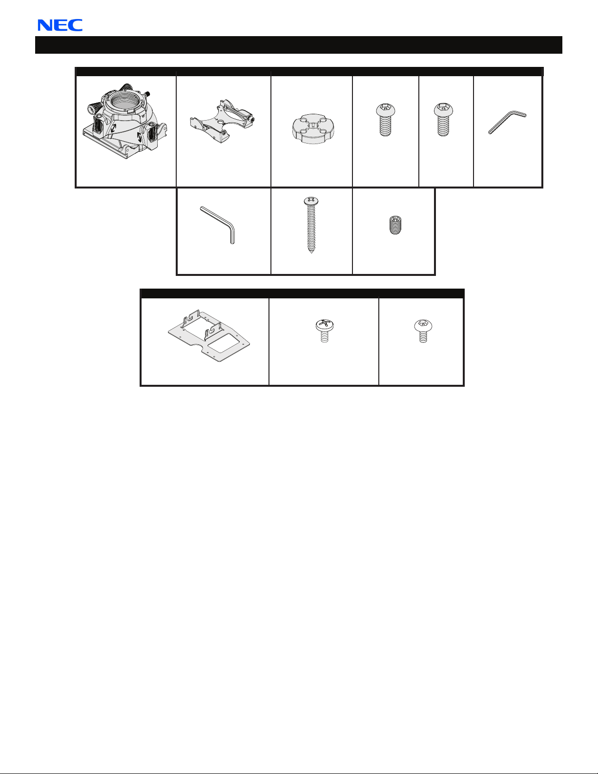
Parts List (cont’d)
NPLTWM
FTP Hardware
FTP Dome
(Qty 1)
Quick Set Base
(Qty 1)
M5 Allen Wrench
(Qty 1)
Projector Bracket (Qty 1)
Installation Disk
(Qty 1)*
#14 x 3” Wood Screw
(Qty 1)*
Projector Bracket Hardware
M4 x 10mm
Pan Phillips Screw
(Qty 4)
M5 x 12mm
Security Screw
(Qty 1)
M6 x 6mm
Set Screw (Qty 1)*
M4 x 10mm Lock-It™
Security Screw
(Qty 4)
M6 x 8mm
Security
Screw
(Qty 4)
*Note: Depending on your
installation, these parts
may not be needed.
M3 Allen Wrench
(Qty 1)
Page 4
Installation Instructions
Page 5
NPLTWM
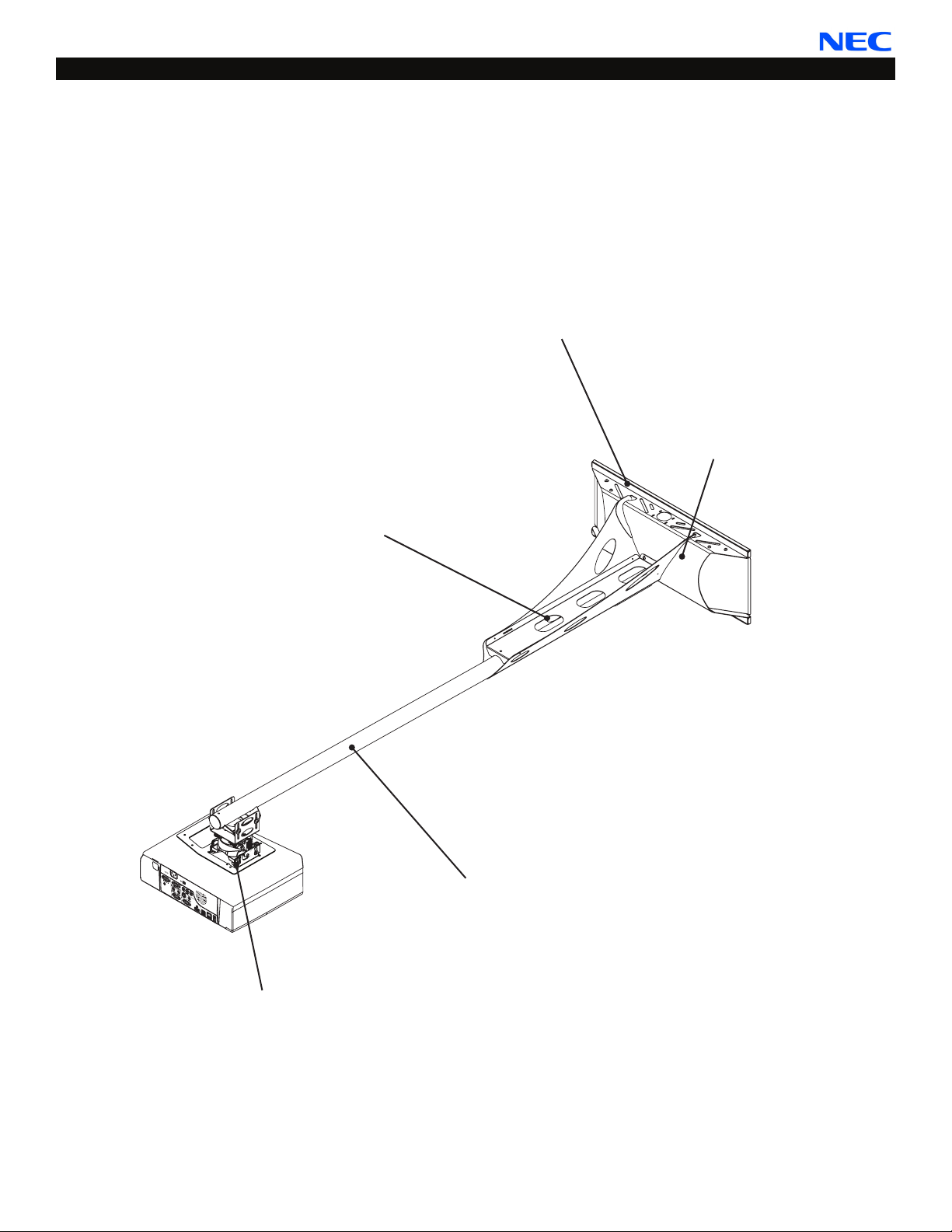
Projector Mount Features
The short-throw projector arm (NPLTWM) is one of the most exible and installer-friendly short-throw arms on the market.
It is designed specically for the NEC M300W and M300WS projectors. The mount easily adjusts from 7” to 67” from the
wall if used with the extension arm. Its ne-tune controls lets the installer adjust pitch, roll, and yaw independently. After
aligning the projectors image to the nal projection settings, the mount can be locked in position with one thumb screw.
To make installations even easier, an array of mounting points at the top and bottom of the GearBox™ allows you to
mount the NPLTWM off-center from the stud spacing, if needed. The NPLTWM mounts to dual studs at 16”, 18” or 24”
spacing.
Flexible Mounting Options
Mounts to dual wood studs (16”,
18” or 24” spacing)
A/V Equipment Security
Patent-pending GearBox™ for
PC, Mac mini™ or control
modules is secured with Lock-It™
security hardware.
Cable routing
Discreetly manage signal and
power cables through the arm and
into the GearBox™
Model-Specic Mount
The mount is specically designed
for the NEC M300W and M300WS
projectors and features
independent ne-tune controls
Installation Instructions
Optional Arm Extension
Extends the projector up to 67”
from the wall
Page 5
Page 6
NPLTWM
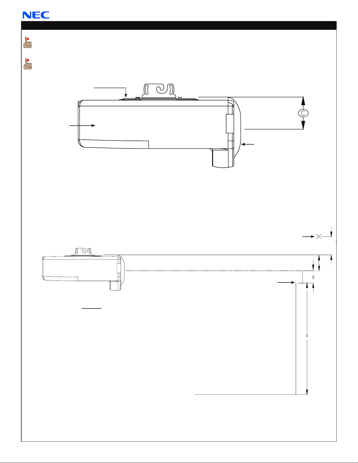
Determining the Installation Height
In order to determine the installation height and throw distance, the projector bracket must be mounted
to the projector. Please refer to the projector bracket installation instructions (page 15) prior to performing the
following steps.
Refer to the projector’s User Manual to determine the offset of the projector lens to the top of the
screen/whiteboard (B).
Projector Bracket
Projector
Lens
Measure distance from center of lens to the top of the projector mounting bracket (C).
➊
Add the distance from the ground to the top of the screen (A). Add the projector manufacturers recommended
➋
offset from the projector manual (B), then add the measurement from Step 1 (C). Lastly, add 3.8” to the total.
(Example: A + B + C + 3.8˝= ?)
Add the measurements to determine the mounting height mark. Place a mark at the top of the total calculated
➌
height measurement starting from the ground up. This mark will represent the lower edge of the wall plate.
Legend
A - Distance from ground to the top of the
screen/whiteboard (viewable area).
B - Manufacturers recommended offset
measurement. This measurement will
be listed in the Users Manual.
C - Center of the lens to the top of the
projector bracket.
This total distance will be the location for
the bottom rail on the wall plate.
Mark
+2.5"/+2.8"/+3.8"
Top of Screen
Ground
Proceed to the “Wood Stud Installation”
section.
Page 6
Installation Instructions
Page 7

NPLTWM
Wood Stud Installation
Do NOT over-tighten lag bolts when attaching the mount to the wall. Improper installation may result in personal
injury or damage to property.
THE EXACT CENTER OF THE STUD MUST BE LOCATED FOR CORRECT AND SAFE INSTALLATION.
Step 1
Use an electronic stud nder (not supplied) to
locate the center of the stud that is in the wall.
Stud nder
Wood Stud
Step 2
Use a pencil to mark the rst mounting point, just
above your height mark (from page 6).
Step 3
Use the level to make sure the wall plate is level from
➊
side to side.
Place the wall plate over the rst mounting point mark
➋
and use a pencil to mark the rest of the mounting
points.
Four (4) mounting points must be used. Two (2)
upper mounting points and two (2) lower mounting
points.
Wood Stud
Mounting Point
Mark
Height
Mark
(from page 6)
Marking
Step 4
Once the mounting points have been marked, use a
¼˝ drill bit and portable drill to drill the pilot holes.
Installation Instructions
Drill
Wall
Plate
Marking
Page 7
Page 8

Step 5
After the pilot holes have been drilled, use four (4)
5
˝ x 3˝ lag bolts and four (4) square washers to
16
mount the wall plate to the wooden studs.
Use a ½˝ socket and socket wrench to nish this step.
Step 6
Insert and gently tap the upper and lower back plate
covers into place.
Proceed to the “Attaching the Projector Arm”
section.
NPLTWM
Lag Bolt and Square Washer
Socket
Wall
Plate
Back Plate Covers
Attaching the Projector Arm
Step 1
Locate the mounting hook cutout on the top of the
➊
wall plate.
Tilt the arm slightly and gently insert the mounting
➋
hooks into the mounting hook cutouts.
Slowly lower and let the projector arm rest against
➌
the wall plate.
If using the storage feature of the product, it
may be easier to route any wiring at this time
(please see page 16).
MAKE SURE THE PROJECTOR ARM IS FULLY
SEATED BEFORE RELEASING THE UNIT.
Mounting Hook Cutout
Mounting Hooks
Wall Plate
Projector Arm
Page 8
Installation Instructions
Page 9

NPLTWM
Step 2
Locate the two (2) lock mounting points on the
➊
projector arm. These two points will be aligned with
the lock mounting points on the wall plate.
Using a security wrench, insert and tighten two (2)
➋
M5 x 8mm security head screws.
Do NOT overtighten these screws.
Proceed to the “Throw Distance
Calculation” section.
Lock Mounting
Point
M5 x 8mm Security
Head Screw
Security Wrench
Throw Distance Calculation
Please review the Operator’s Manual that came packaged with your projector before attaching the upper
mounting bracket. The correct throw distance (the distance from the projector to the screen) must be
determined prior to mounting the projector.
Refer to the projectors Users Manual to
➊
determine the distance from the lens to
the front of the screen (X).
Measure the distance from the front of
➋
the lens to the center of the projector (Y).
Measure the distance from the wall to the
➌
face of the whiteboard/screen (Z).
Add all measurements (X + Y + Z) to
➍
determine projector placement on the
arm assembly. This measurement
will determine where the center of the
mount bracket will be located on the
arm assembly. Please make note of this
measurement.
The NPLTWM can be also used as
a wall-mounted standard projector mount as
well as a short throw projector mount. Align
the projector facing the opposite direction
from the wall plate to project the image
across the room. Please take into account
the projectors throw capabilities prior to
mounting in the projector opposite direction
Calculations
X = Manufacturers recommended
throw distance
Z = Distance from wall to face of
whiteboard/screen
Front Lens Throw Distance =
(X + Y + Z)
Front Lens
Proceed to the “Attaching the Projector
Mount” section.
Installation Instructions
Page 9
Page 10

Attaching the Projector Mount
Attach the FTP Dome to the mounting assembly before
attaching the projector itself.
Detach the upper half of the mounting assembly from
➊
the lower half.
Following the “A” mounting-hole pattern (Figure 1),
➋
use four (4) M4 x 10mm security screws to attach the
FTP projector mount to the lower half of the mounting
assembly (Figure 2). Do not overtighten.
Use the four mounting holes on the collar of the FTP.
Re-attach both components of the mounting
➌
assembly.
Are you attaching an extension arm?
If yes, continue to the “Extension Arm Installation
(Optional)” section on page 11.
If no, proceed to the “Adjustable Mounting
Bracket Installation” section on page 12.
A
A
Bottom view of the adjustable
mounting assembly
NPLTWM
A
A
Figure 1
Projector not shown
M4 x 10mm security screw
Figure 2
Page 10
Installation Instructions
Page 11

NPLTWM
Extension Arm Installation (Optional)
Please see the Operator’s Manual to determine the correct throw distance (the distance from the projector to the
screen). The throw distance must be determined prior to mounting the projector (Page 8).
The end cover must be removed prior to installing the extension arm.
Slide the extension arm into the open end of the
➊
NPLTWM (the front of the mount).
Adjust length so that the center of the adjustable
➋
mounting bracket matches the throw distance
calibration.
Line up the mounting holes on the extension arm
➌
with the mounting slots on the NPLTWM.
Using a screwdriver, insert and tighten two (2)
➍
M6 x 12mm security head screws and M6 at
washers through the external slide plate and
tighten.
Security Wrench
Extension Arm
(Optional)
NPLTWM
External Slide
Plate
M6 Flat
Washers
M6 x 12
Security
Screw
Proceed to the “Adjustable Mounting Bracket
Installation” section.
Adjustable
Mounting
Bracket
Installation Instructions
Page 11
Page 12

Adjustable Mounting Bracket Installation
If you are not using the extension arm,
➊
insert the inner slide plate into the
projector arm.
Determine which adjustment slot best
➋
matches your throw distance
calculation (above).
Raise the adjustable mounting bracket
➌
into position.
Align the mounting holes of the upper
➍
mounting plate with the mounting holes
of the inner slide plate or extension arm.
Two (2 - one per screw) ⅛˝ nylon
washers must be placed between the
adjustable mounting bracket and the
projector arm (see inset to the right).
Secure and nger-tighten two (2)
➎
M6 x 16mm security head screws.
NPLTWM
Projector Arm
Adjustment
Slot
Inner Slide
Plate
Upper Mounting
Plate
Adjustable
Mounting
Bracket
Calculated
Throw
Distance
⅛˝ Nylon
Washer
If needed, determine the Throw Distance
➏
again.
Once the correct throw distance has been
➐
determined, use the security wrench
(supplied) to tighten the mounting screws.
If the adjustable mounting bracket needs
to be adjusted, the four (4) M6 x 12mm
security screws may be loosened so that
the bracket can be moved ±2˝. Once the
desired height has been achieved,
re-tighten the hardware.
M6 x 16mm
Security
Screw
Security
Wrench
Do NOT overtighten these screws.
Proceed to the “Attaching the Projector
Bracket” section.
Page 12
Installation Instructions
Page 13

NPLTWM
Attaching the Projector Bracket
Lock-It™ Security Hardware Pack
Your projector bracket comes with the option of using
Lock-It™ Security Screws. Simply replace any of the
Phillips head screws with the corresponding sized LockIt™ Security screws and tighten using the appropriate
Security Allen wrench.
When you see these graphics associated with a step, you
have the option of using the standard mounting hardware
or the Lock-It™ Security hardware.
Step 1
Invert the projector and place it on a soft, at surface.
➊
Remove any foot levelers that might prevent bracket
➋
installation.
Locate the mounting points on the projector.
➌
Place the bracket on the projector (Figure 1).
➍
Bottom of projector shown is
for example purposes only.
Step 2
Align the mount holes on the bracket with the
➊
mounting points on the projector.
If you are using the NEC M300W projector, use the
mount holes labeled “A”. If you are using the NEC
M300WS projector, use the mount holes labeled “B”.
See Figure 2.
Insert one (1) M4 x 10mm pan Phillips screw or one
➋
(1) M4 x 10mm Lock-It™ security screw into each
mounting point.
Tighten the mounting hardware.
➌
Do not overtighten the mounting screws.
Figure 1
Figure 2
A
A
B
B
A
B
B
A
Installation Instructions
Page 13
Page 14

Attaching the Projector Bracket (cont’d)
Step 3
NPLTWM
Slide the quick set base into the projector plate and hook
the projector plate over the quick set base hinge pins
(Figure 1).
Step 4
Quick Set Base
Figure 1
Insert one (1) M6 x 8mm security screw into each of
➊
the indicated locations. See Figure 2.
Proceed to the “Attaching the Projector Mount”
➋
section.
Step 5
Hand tighten the captive screw.
➊
Insert one (1) M5 x 12mm security screw into location
➋
“B” to tighten the Quick Set Base to the FTP Dome
(Figure 3).
Figure 2
Captive
Screw
B
Proceed to the “Attaching the Projector Mount”
➌
section.
Page 14
Figure 3
Installation Instructions
Page 15

NPLTWM
Alignment & Fine-Tuning
Yaw
Yaw can be adjusted up to 20° left and 20° right from center.
Adjust the projector’s yaw by
turning control ...
...clockwise to pivot the front
to the right.
...counter-clockwise to pivot
the front to the left.
Each full revolution of the
control adjusts the yaw
by 4°.
Pitch
Pitch can be adjusted 15° down and 5° up from level.
Adjust the projector’s pitch
by spinning control ...
...right to pitch the front
down.
...left to pitch the front up.
Each full revolution of the
control adjusts the pitch
by 1°.
Roll
Roll can be adjusted up to 5˚ to either side from level.
Adjust the projector’s roll by
spinning control ...
...left to roll the right side
up.
...right to roll the right side
down.
Installation Instructions
Each full revolution of the
control adjusts the roll by 1°.
Page 15
Page 16

Locking in the Adjustments
NPLTWM
After you have nalized your yaw, pitch, and roll
adjustments, you can lock them in to prevent them from
being accidentally changed.
Finger-tighten the knurl knob until it makes rm
➊
contact with the FTP Support Sphere (Figure 1).
The M6 set screw on the front of the FTP Dome
provides tension for the roll, pitch and yaw
adjustments. This is a factory setting which you
should not change (Figure 2).
Figure 2
FTP Support Sphere
Figure 1
Utilizing the Storage Feature
The storage feature may be used to store electronic
components. There is an accessible door on each side of the
storage enclosure. It may be securely held shut with the use of
four (4) M5 x 8mm security head screws. It may be easiest to
pre-wire all cables down the arm (or extension) at this time.
Open the storage door that is located on the
➊
side of the wall plate.
Place the electronic components inside the
➋
storage enclosure.
Make all electronic connections at this time.
➌
Close the storage door and secure using two
➍
(2; 1 upper and 1 lower) M5 x 8mm security
head screws. Tighten using a security wrench.
Repeat this process for the other side as well.
Proceed to the “Cable Management” section.
Electronic
Components
Door
Security
Wrench
M5 x 8mm
Security Screw
Page 16
Installation Instructions
Page 17

NPLTWM
Cable Management
The cable access holes are located at the end of the
➊
short throw mount and on the wall plate.
Route the cables through one end of the NPLTWM
➋
and out the other end.
Attach the end cover with an M5 x 8mm security
➌
head screw.
You may direct the cables out the end of the
NPLTWM. The end cover has a
perforated tab to allowcables to pass out the end.
Pliers must be used to bend the perforated tab. If
the cables will not t, the end cover may be
removed by loosening and extracting the
M5 x 8mm security screw.
NPLTWM
Cable Opening
Electronic
Components
Cables
Cable Opening
Projector
Connections
NPLTWM
M5 x 8mm
Security Screw
End Cover
Extension Bracket
Installation Instructions
Perforated Tab
Page 17
Page 18

Technical Specications
All measurements are in inches(mm).
NPLTWM
Page 18
Installation Instructions
Page 19

NPLTWM
Disclaimer
NEC intends to make this manual accurate and complete. However, NEC makes no claim that the information
contained herein covers all details, conditions or variations, nor does it provide for every possible contingency in
connection with the installation or use of this product. The information contained in this document is subject to change
without notice or obligation of any kind. NEC makes no representation of warranty, expressed or implied, regarding
the information contained herein. NEC assumes no responsibility for accuracy, completeness or sufciency of the
information contained in this document.
Installation Instructions
Page 19
 Loading...