

Page 1
NEC DISPLAY SOLUTIONS OF AMERICA, INC.
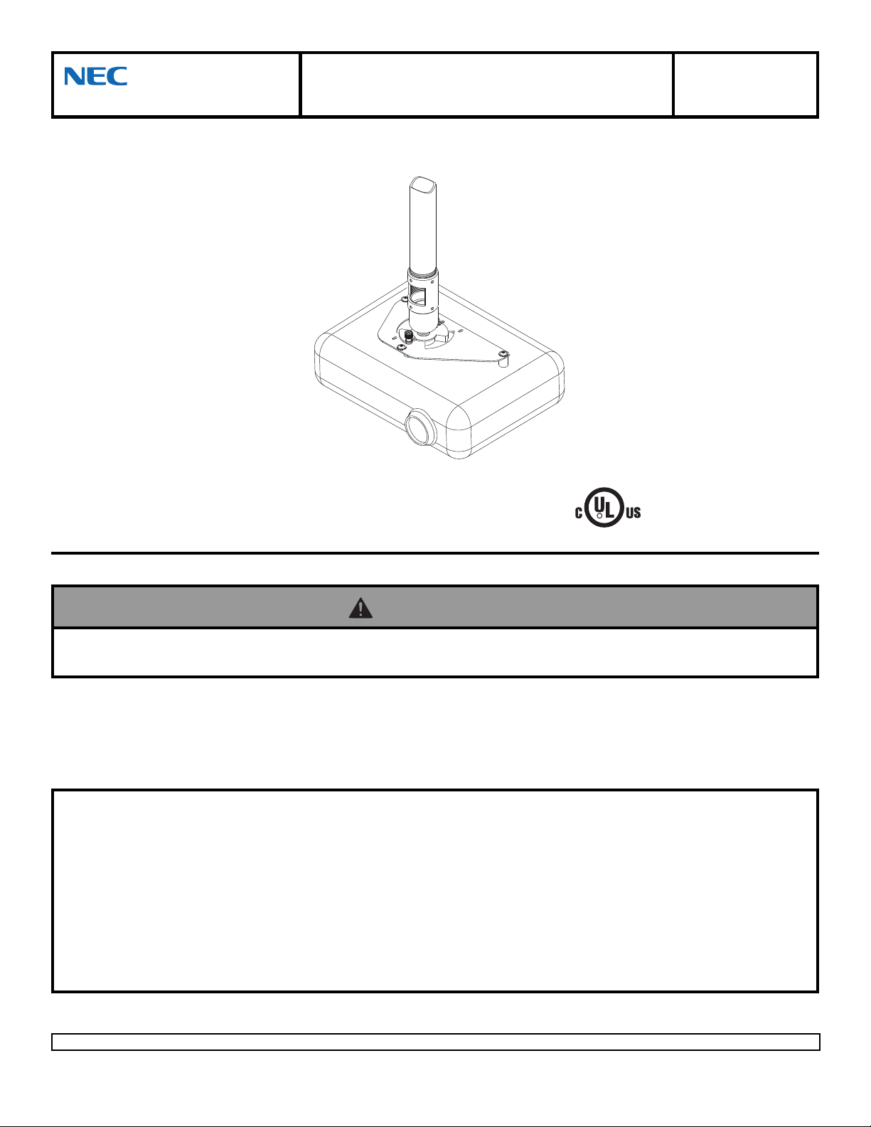
Installation and Assembly -Ceiling Mount for
NEC NP 40/41/50/60/61/62/100/200 Projectors
Model: NP40CM
This product is intended for use with UL
R
Listed products and must be installed by a
qualified professional installer.
Maximum Load Capacity: 50 lb (22.7 kg)
Read instruction sheet before you start inst allation and assembly.
WARNING
• Make sure that the supporting surface will safely support the combined load of the equipment and all attached hardware and
components.
IMPORT ANT! Be sure not to touch the projector while tightening the set screw on the
ball and socket mount. This may cause the image to be unaligned when you let go.
IMPORT ANT! T urn to the appropriate page for your ceiling inst allation.
Applications:
Flush Mount.................................................................................................................................................. page 5
Extension Column............................................................................................................... ......................... page 6
Installations:
To Wood Joist Finished Ceilings,
Exposed Wood Joists, or Wood Beam Ceilings........................................................................................page 3
T o Concrete Ceilings.................................................................................................................................... page 4
Visit the Peerless Web Site at www.peerlessmounts.com
1 of 8
For customer care call 1-800-729-0307 or 708-865-8870.
ISSUED: 11-01-06 SHEET #: 055-9478-6 01-14-09
Page 2
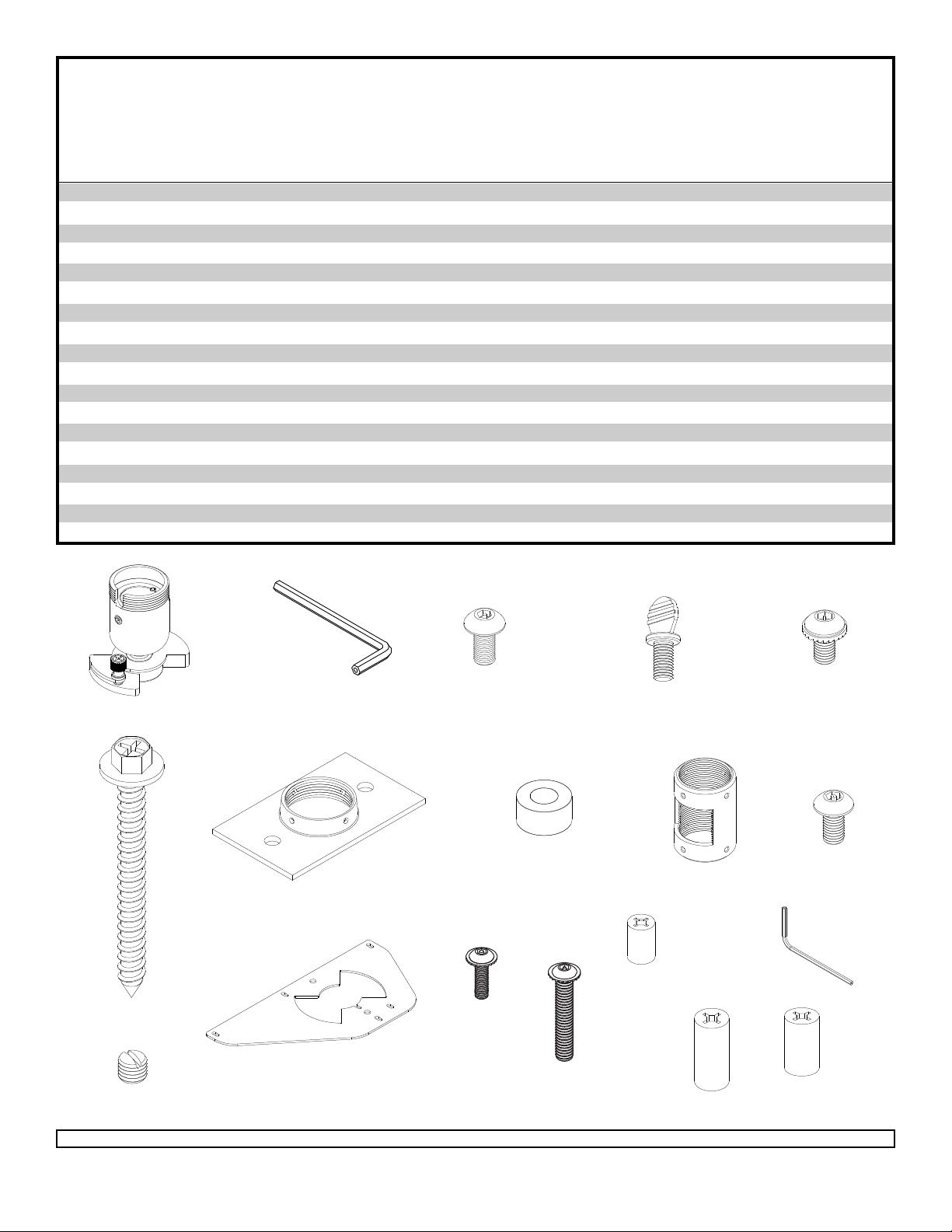
Before you start check the parts list to insure all of the parts shown are included.
Description Qty. Part Number
A ball and socket mount 1 055-0016
B 4 mm security allen wrench 1 560-9646
C M5 x .8 x 10 mm socket pin type F screw 1 520-2031
D #10-32 x 3/8" spade thumb screw 1 560-2107
E #10-32 x 3/8" serrated washer head socket pin screw 1 520-2151
F #14 x 2.5 phillips hex head wood screw 2 5S1-015-C04
G ceiling plate 1 580-4042
H .25" ID x .56" OD x .26 spacer 2 590-2071
I extension column connector with cord management 1 580-4025
J #10-32 x 3/8" socket pin screw 2 520-2084
K #10-32 x 3/16" slotted set screw 3 520-2187
L adapter plate 1 055-4808
M M3 x 16 mm serrated socket pin screw 1 510-2083
N M3 x 25 mm serrated socket pin screw 3 510-2127
O .156 x .375 retaining spacer 1 590-2140
P .198 x .750 retaining spacer 3 590-2134
Q 2 mm security allen wrench 1 560-1097
R .198 x .313 x .688 H retaining spacer 3 590-2131
Parts List
A
B
C
H
G
F
L
K
Note: Actual parts may appear slightly different than illustrated.
Visit the Peerless Web Site at www.peerlessmounts.com
M
N
2 of 8
For customer care call 1-800-729-0307 or 708-865-8870.
D
E
I
J
O
P
ISSUED: 11-01-06 SHEET #: 055-9478-6 01-14-09
Q
R
Page 3
Installation To Wood Joist Finished Ceilings,
Exposed Wood Joists, or Wood Beam Ceilings
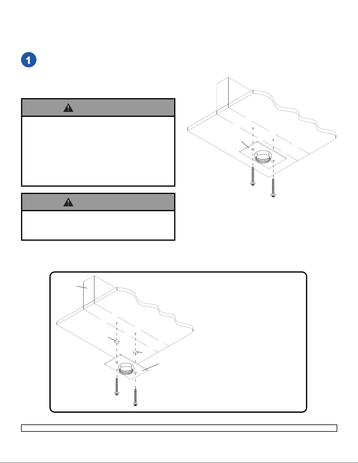
Drill two 5/32" (4 mm) dia. holes to a minimum
depth of 2.5" (64 mm). Attach ceiling plate (G)
with two #14 x 2.5" (6 mm x 65 mm) wood
screws (F) as shown using 3/8" (10 mm) socket
wrench.
Skip to step 2.
WOOD
JOIST
WARNING
• Tighten wood screws (F) so that ceiling plate (G) is
firmly attached, but do not overtighten. Overtightening
can damage the screws, greatly reducing their holding
power.
• Never tighten in excess of 80 in • lb (9 N.M.).
• Make sure that mounting screws are anchored into the
center of the studs. The use of an "edge to edge" stud
finder is highly recommended.
WARNING
• It is the responsibility of the installer to verify that the
supporting surface will safely support the combined
load of all attached hardware and components.
IMPORTANT: Be sure to drill holes into the
joist CENTER!
CEILING
G
F
F
WOOD
JOIST
CEILING
H
F
Visit the Peerless Web Site at www.peerlessmounts.com
F
H
G
3 of 8
For optional Cord Management,
install two spacers (H) between ceiling
plate (G) and ceiling.
ISSUED: 11-01-06 SHEET #: 055-9478-6 01-14-09
For customer care call 1-800-729-0307 or 708-865-8870.
Page 4
WARNING
• When installing Peerless mounts on concrete, verify that you have a minimum of 1 5/8" of actual concrete surface in
the 1/4" diameter hole to be used for the concrete anchors. Do not drill into mortar joints! Concrete must meet ASTM
C-90 specifications.
• Concrete must be 2000 psi density minimum. Lighter density concrete may not hold concrete anchor .
• Make sure that the supporting surface will safely support the combined load of the equipment and all attached hardware and components.
• Never exceed the Maximum UL Load Capacity of 50 lb (27 kg).
Installation to Concrete Ceilings
ACC 203 (Alligator® concrete anchors) are recommended.
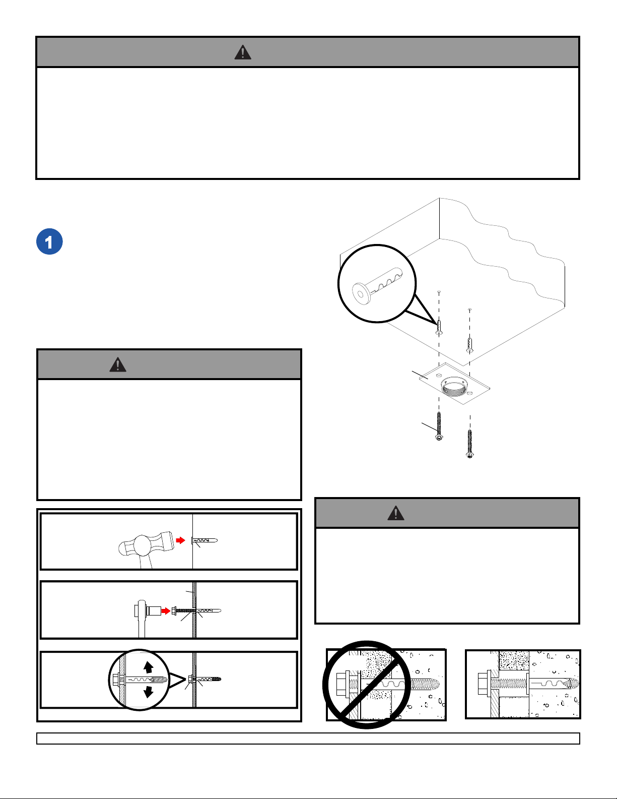
Drill two 1/4" (6 mm) dia. holes to a minimum depth of
2.5" (64 mm). Attach ceiling plate (G) using two
concrete anchors and #14 x 2.5" wood screws (F) as
shown in Illustration A and 1, 2, and 3 (below).
Tighten all fasteners.
IMPORTANT: It is the responsibility of the installer
to verify that the ceiling will safely support the
combined load of all attached hardware and
components.
concrete
anchor
CONCRETE CEILING
WARNING
• Tighten wood screws so that ceiling plate is firmly
attached, but do not overtighten. Overtightening can
damage the screws, greatly reducing their holding
power.
• Never tighten in excess of 80 in • lb (9 N.M.).
• Make sure that mounting screws are anchored into the
center of the studs. The use of an "edge to edge" stud
finder is highly recommended.
1
Drill hole and insert anchor
2
G
F
Place ceiling plate over anchor and secure with screw
3
concrete
ceiling
concrete
anchor
concrete
anchor
G
F
Illustration A
WARNING
• FOR DIRECT ATT ACHMENT T O LOAD BEARING
CONCRETE ONL Y! Concrete expansion anchors are
not intended for attachment to concrete ceilings
covered with a layer of plaster, drywall, or other
finishing material. If mounting to concrete ceiling
covered with plaster / drywall is unavoidable, plaster /
drywall must be counterbored as shown below.
metal
bracket
INCORRECT
concrete
metal
bracket
CORRECT
concrete
concrete
F
After repeating step one tighten all fasteners
Visit the Peerless Web Site at www.peerlessmounts.com
anchor
4 of 8
CUT AW A Y VIEW
plaster/
dry wall
ISSUED: 11-01-06 SHEET #: 055-9478-6 01-14-09
For customer care call 1-800-729-0307 or 708-865-8870.
plaster/
dry wall
Page 5
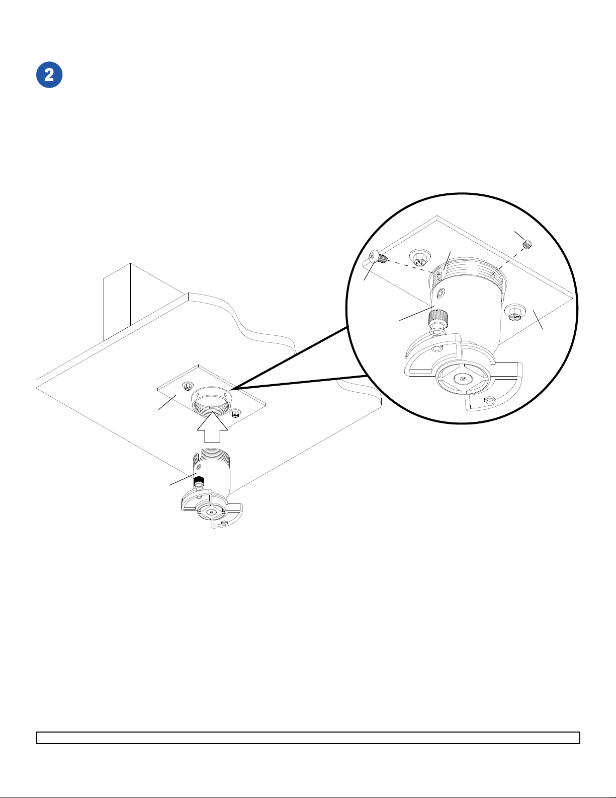
Flush Mount Application
Screw ball and socket mount (A) into ceiling plate (G). Align the notch with one of the four holes of the ceiling plate
(G) and secure ball and socket mount (A) with a M5 x 10 mm socket pin screw (C) using security allen wrench (B)
as shown in detail 1.
Note: Slotted set screw (K) is used to jam against the threads of the ball and socket mount to prevent any excess
movement of the ball and socket mount (A). Do not overtighten screw; overtightening screw will damage threads
making it difficult to separate the products.
Skip to step 3.
K
NOTCH
CEILING
WOOD
G
A
C
A
G
DETAIL 1
Visit the Peerless Web Site at www.peerlessmounts.com
5 of 8
ISSUED: 11-01-06 SHEET #: 055-9478-6 01-14-09
For customer care call 1-800-729-0307 or 708-865-8870.
Page 6
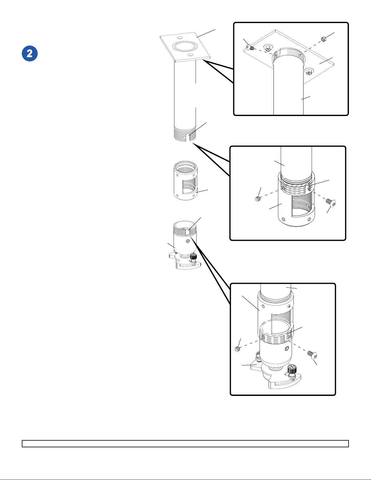
Installation to
Extension Column
G
C
K
Screw extension column to ceiling plate (G).
Align the notch with one of the four holes in
the ceiling plate (G) and secure extension
column with a M5 x 10 mm socket pin
screw (C) using security allen wrench (B).
See detail 4.
Screw extension column connector (I) to
extension column. Align slot in extension
column with one of the top holes in
extension column connector (I). Insert and
tighten one #10-32 x 3/8" socket pin screw
(J) through extension column connector (I)
into slot on extension column using security
allen wrench (B). See detail 5.
Screw ball and socket mount (A) to
extension column connector (I). Align slot in
ball and socket mount (A) to one of the
bottom holes in extension column connector
(I). Insert and tighten one #10-32 x 3/8"
socket pin screw (J) through extension
column connector into slot in ball and
socket mount (A) using security allen
wrench (B). See detail 6.
EXTENSION COLUMN
(UL Listed EXT or ADJ
Series)
Sold Separately
SLOT
I
SLOT
EXTENSION
COLUMN
K
I
G
EXTENSION
COLUMN
DETAIL 4
SLOT
J
Note: Slotted set screws (K) are used to
jam against the threads of each connecting
joint to prevent any excess movement. Do
not overtighten screws; overtightening
screws will damage threads making it
difficult to separate the products.
A
I
A
DETAIL 5
EXTENSION
COLUMN
SLOT
K
J
DETAIL 6
Visit the Peerless Web Site at www.peerlessmounts.com
6 of 8
ISSUED: 11-01-06 SHEET #: 055-9478-6 01-14-09
For customer care call 1-800-729-0307 or 708-865-8870.
Page 7
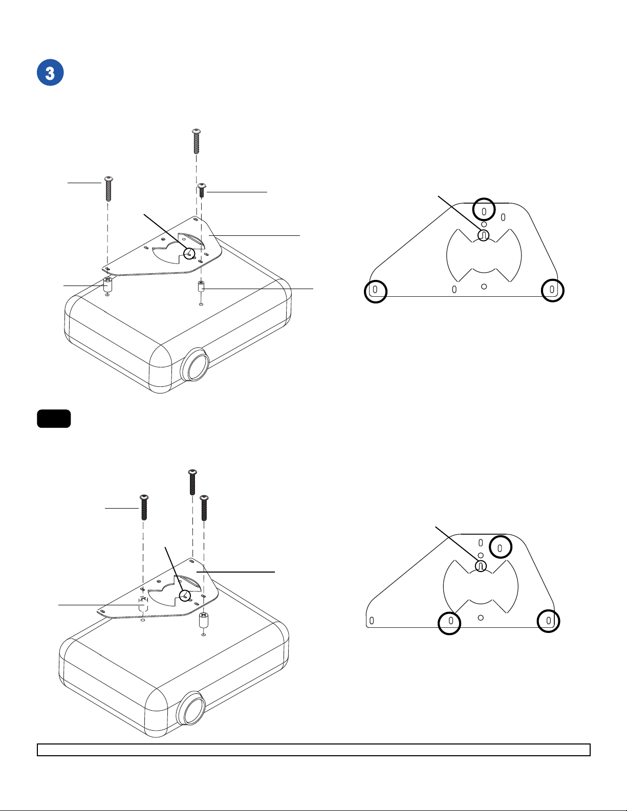
Find your projector from the models listed below
*Notch indicates front of projector.
Flip projector upside down and remove feet from bottom of projector. Fasten two M3 x 25 mm socket pin
screws (N) and two .198 x .750 retaining spacers (P) into the threaded inserts as indicated below . Fasten one
M3 x 16 mm socket pin screw (M) and one .156 x .375 retaining spacer (O) into the threaded insert as indicated below. Finish tightening screws (N, M) using 2 mm security allen wrench (Q).
N
P
3-1
M
*
*
L
O
A. NEC NP40/41/50/60/61/62
*Notch indicates front of projector.
Flip projector upside down and fasten three M3 x 25 mm socket pin screws (N) and three .198 x .313 x .688
retaining spacers (R) into the threaded inserts as indicated below . Finish tightening M3 x 25 mm socket pin
screws (N) using 2 mm security allen wrench (Q).
N
*
R
Visit the Peerless Web Site at www.peerlessmounts.com
L
7 of 8
*
B. NEC NP100/200
ISSUED: 11-01-06 SHEET #: 055-9478-6 01-14-09
For customer care call 1-800-729-0307 or 708-865-8870.
Page 8
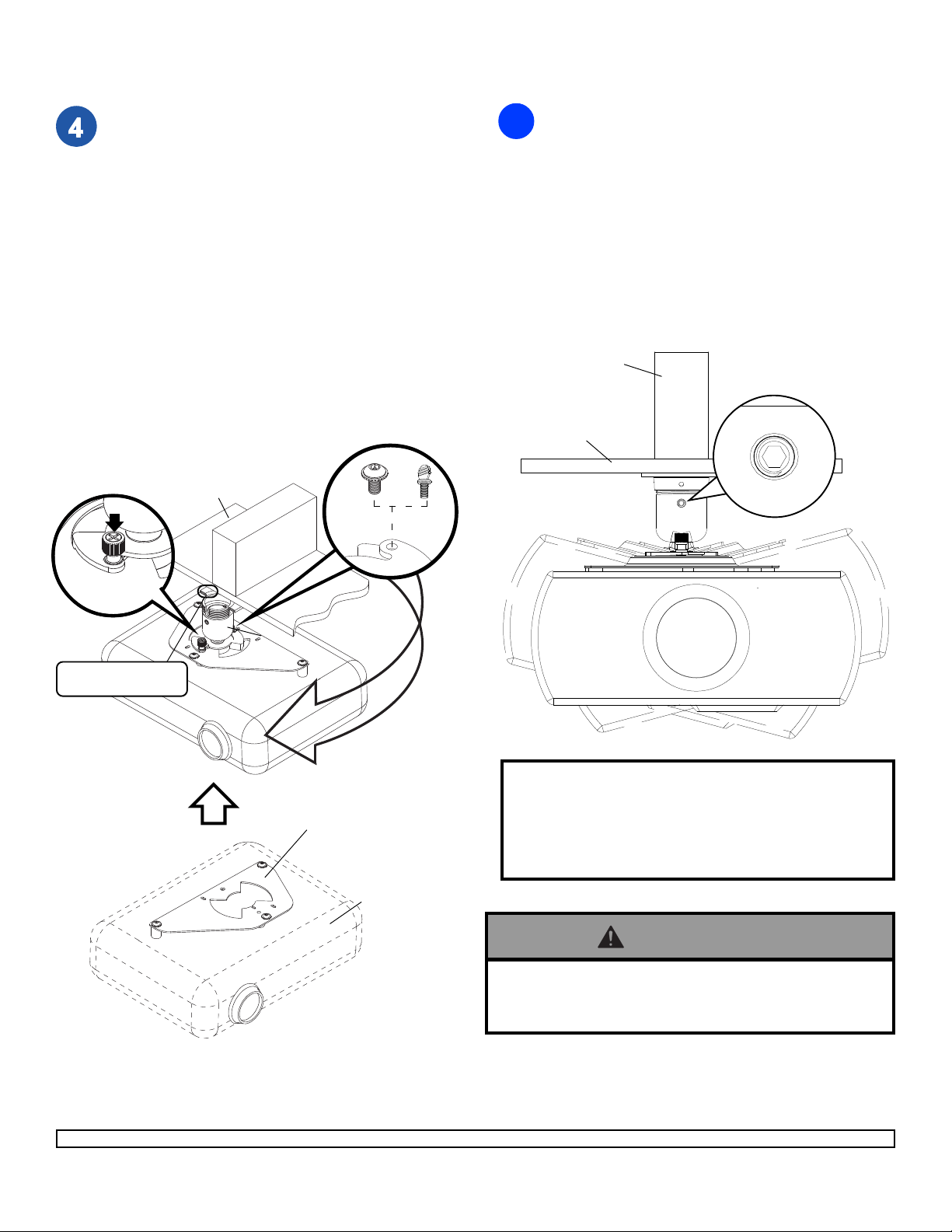
Note: The projector adapter plate and projector you are installing may differ in appearance from the sample
illustrated below.
Attach projector, with adapter plate already on it, to the
ball and socket mount (A) by inserting the ball and
socket mount (A) into the adapter plate connection and
twisting until the adapter plate will no longer turn
(about 75°). The spring loaded captive screw should
line up with a corresponding hole on the adapter plate
(this should line up automatically when the two are
connected). Push down and tighten the spring loaded
captive screw to secure the adapter plate to the mount.
If not using the optional security feature, fasten thumb
screw (D) in the hole opposite the spring loaded
captive screw.
™
OPTIONAL: For Armor Lock
washer head socket pin security screw (E) in the hole
opposite the spring loaded captive screw. Tighten with
security allen wrench (B). This will prevent the
projector from being removed.
Note: Be sure to only use the #10-32 x 3/8" screw (E)
(or the thumb screw (D)) opposite the spring loaded
captive screw.
CEILING
CAPTIVE
SCREW
security, insert serrated
E
WOOD
JOIST
A
D
To adjust roll, pitch, and yaw loosen the set screw
5
(shown below) using security allen wrench (B) or
standard 4 mm allen wrench. You should be able to
just slightly loosen the screw so that your adjustments
can be set without having to hold the projector. Move
projector to desired position and slowly tighten set
screw.
Note: Be sure not to touch the projector while
tightening the set screw. This may cause the image
to be unaligned when you let go.
IMPORTANT: Allen wrench is your key for projector
removal. Store it in a safe place.
WOOD
JOIST
CEILING
SET SCREW
PROJECTOR
CUTA W AY VIEW OF
CEILING PLATE ( G)
1
2
PROJECTOR ADAPTER PLATE
(UL Listed PAP Series)
Sold Separately
PROJECTOR
Peerless offers several Projector Mounts to fit various
projectors. New Projector Mounts are continually being
developed to meet the demands of a growing projector
market. To find out if a mount is available for your particular
projector, call Peerless customer service at 1-800-7290307 or 1-708-865-8870.
WARNING
• Do not lift more weight than you can handle! Use
additional man power or mechanical lifting equipment
to safely handle placement of the projector!
Visit the Peerless Web Site at www.peerlessmounts.com
8 of 8
For customer care call 1-800-729-0307 or 708-865-8870.
All other brand and product names are trademarks or registered trademarks of their respective owners.
ISSUED: 11-01-06 SHEET #: 055-9478-6 01-14-09
© 2008, Peerless Industries, Inc. All rights reserved.
 Loading...