

Page 1

()
■ ■ ■ ■ ■ ■ ■
■ ■ ■ ■ ■ ■ ■
■ ■ ■ ■ ■ ■ ■
■ ■ ■ ■ ■ ■ ■
■ ■ ■ ■ ■ ■ ■
■ ■ ■ ■ ■ ■ ■
■ ■ ■ ■ ■
■ ■
■ ■ ■ ■ ■ ■ ■
■ ■ ■ ■ ■ ■ ■
■ ■ ■ ■ ■ ■ ■
■ ■ ■ ■ ■ ■ ■
■ ■ ■ ■ ■ ■ ■
■ ■ ■ ■ ■ ■ ■
■ ■ ■ ■ ■ ■ ■
User Guide
NovaScale R630
Page 2

Proprietary Notice and Liability Disclaimer
The information disclosed in this document, including all designs and related materials, is
the valuable property of NEC Computers and/or its licensors. NEC Computers and/ or its
licensors, as appropriate, reserve all patent, copyright and other proprietary rights to this
document, including all design, manufacturing, reproduction, use, and sales rights thereto,
except to the extent said rights are expressly granted to others.
To allow for design and specification improvements, the information in this document is
subject to change at any time, without notice. Reproduction of this document or portions
thereof without prior written approval of NEC Computers is prohibited.
The Bull product(s) discussed in this document are warranted in accordance with the terms
of the Warranty Statement accompanying each product. However, actual performance of
each product is dependent upon factors such as system configuration, customer data, and
operator control. Since implementation by customers of each product may vary, the
suitability of specific product configurations and applications must be determined by the
customer and is not warranted by Bull.
rev 1.0 October 2007
Copyright 2007
NEC Computers S.A.S.
All Rights Reserved
Page 3
iii
Keep this User's Guide handy for quick reference when necessary.
SAFETY INDICATIONS
To use Server series safely, follow the instructions in this User's Guide.
This guide explains components that pose a danger, types of dangers, and actions taken to prevent them; such
components are labeled warning.
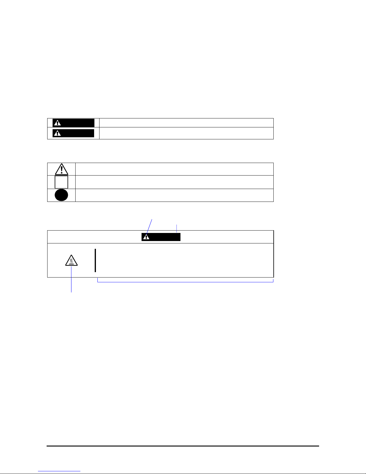
This guide and warning labels use “WARNING” and “CAUTION” to indicate a danger depending on the degree. These
terms are defined as follows:
WARNING
Indicates a danger that could lead to a death or serious injury.
CAUTION
Indicates a danger that could lead to a burn, other injuries or damage to
physical assets.
This guide uses the following three types of symbols to give indications and precautions against a danger. They are
defined as follows:
Indicates that there is a risk of danger. Each image symbolizes a particular type of
danger. (Attention)
Indicates what you must not do. Each image symbolizes a particular type of
prohibition. (Prohibited actions)
Indicates what you must do. Each image symbolizes a particular type of action
necessary to avoid a danger. (Mandatory actions)
(Example)
Symbol to draw attention
Term indicating a degree of danger
CAUTION
High temperature.
Immediately after the power-off, system components such as hard disk are
very hot. Wait the server to cool down completely before adding/removing
some component.
Symbol indicating a prohibited
action (may not always be
indicated)
Description of a danger
Page 4
iv
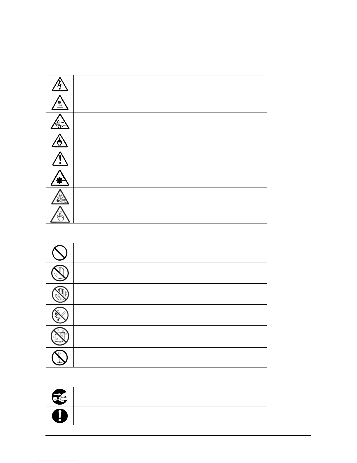
SYMBOLS USED IN THIS USER'S GUIDE AND WARNING LABELS
Attention
Indicates a risk of an electric shock.
Indicates a risk of a personal injury due to heat.
Indicates a risk of catching your fingers.
Indicates a risk of a fire or smoke.
Indicates a general precaution or warning that is not defined herein.
Indicates a risk of losing eyesight due to laser beam.
Indicates a risk of an explosion.
Indicates a risk of a personal injury.
Prohibited actions
Indicates a general prohibition that is not defined herein.
Do no touch the indicated area. There is a risk of an electric shock or fire.
Do not touch with wet hands. There is a risk of an electric shock.
Keep from flame. There is a risk of a fire.
Avoid using water or liquid nearby. If it spills on the equipment, there is a risk of an
electric shock or fire.
Do not disassemble, repair, or modify the equipment. There is a risk of an electric
shock or fire.
Mandatory actions
Unplug the server. There is a risk of an electric shock or fire.
Indicates a general action to take that is not defined herein. Make sure to follow the
instructions.
Page 5
v
NOTE: This equipment has been tested and found to comply with the limits for a Class A digital device, pursuant to
Part 15 of the FCC Rules. These limits are designed to provide reasonable protection against harmful interference when
the equipment is operated in a commercial environment. This equipment generates, uses, and can radiate radio
frequency energy and, if not installed and used in accordance with the instruction manual, may cause harmful
interference to radio communications. Operation of this equipment in a residential area is likely to cause harmful
interference in which case the user will be required to correct the interference at his own expense.
This class A digital apparatus meets all requirements of the Canadian Interference-Causing Equipment
Regulations.
Cet appareil numérique de la classe A respecte toutes les exigences du Règlement sur le matériel brouilleur du Canada.
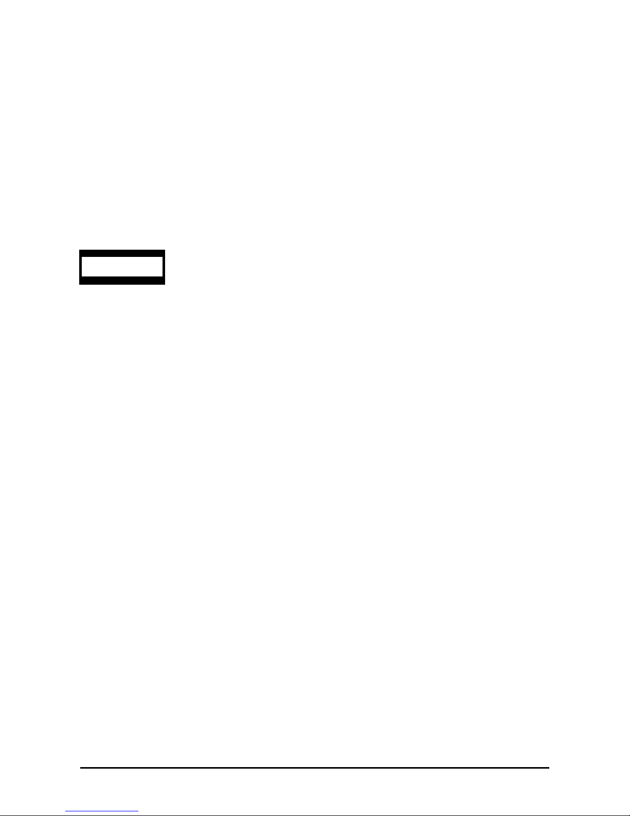
This system is classified as a CLASS 1 LASER PRODUCT. This label id located on the internal
DVD-ROM installed in your system.
NOTE: This product provides resistance against hardware faults with its redundant hardware modules. However, this
does not mean complete fault-tolerance is assured. For example, there is a risk of system down when:
– A fatal fault occurs in software.
– Both modules within a redundant hardware pair break down.
– A fatal fault occurs in a non-redundant component, such as the clock generator circuitry or the interconnect
backplane.
– The entire system is cut off from AC power.
CLASS 1
LASER PRODUCT
Page 6

vi
Trademarks and Patents
EXPRESSBUILDER and NEC ESMPRO are trademarks of NEC Corporation.
Microsoft, and Windows are registered trademarks of Microsoft Corporation in the United States and other countries.
All other product, brand, or trade names used in this publication are the trademarks or registered trademarks of their
respective trademark owners.
Microsoft Windows Server 2003 R2 Standard x64 Edition operating system, Microsoft Windows Server 2003 R2
Enterprise x64 Edition operating system, Microsoft Windows Server 2003 Standard x64 Edition operating system, and
Microsoft Windows Server 2003 Enterprise x64 Edition operating system are called Windows Server x64 Edition for
short.
Microsoft Windows Server 2003 R2 32-bit Standard Edition operating system, Microsoft Windows Server 2003 R2
32-bit Enterprise Edition operating system, Microsoft Windows Server 2003 Standard Edition operating system and
Microsoft Windows Server 2003 Enterprise Edition operating system are called Windows Server 2003 for short.
Microsoft Windows 2000 Server operating system, Microsoft Windows 2000 Advanced Server operating system and
Microsoft Windows 2000 Professional operating system are called Windows 2000 for short. Microsoft Windows Vista
Business operating system is called Windows Vista for short. Microsoft Windows XP Professional x64 Edition
operating system is called Windows XP x64 Edition for short. Microsoft Windows XP Home Edition operating system
and Microsoft Windows XP Professional op erating system is called Windows XP for short. Microsoft Windows NT
Server network operating system version 3.51/4.0 and Microsoft Windows NT Workstation operating system version
3.51/4.0 are called Windows NT for short. Microsoft Windows Millennium Edition Operating System is called
Windows Me for short. Microsoft Window s 98 operating system is called Windows 98 for short. Microsoft Windows 95
operating system is called Windows 95 for short.
Names used with sample applications are all fictitious. They are unrelated to any existing product names, names of
organizations, or individ ual n ames.
To prevent voltage sag:
This product may be affected by voltage sag caused due to lightning. To prevent voltage sag, you are recommended to
use an AC uninterruptible power supply (UPS) unit.
Page 7

vii
PREFACE
Welcome to the Fault Tolerant Server series.
Fault Tolerant Server series is a “fault-tolerant (ft)” server focusing on “high reliability” in terms of fault-tolerance, in
addition to “high performance,” “scalability,” and “general versatility” provided by Server series. In the event of trouble,
its dual configuration will allow the system to instantaneously isolate the failed parts to assure non-stop running;
operation will be moved smoothly from one module to the other, minimizing damage to it. You can use this Fault
Tolerant Server series in a mission-critical system where high availability is required. By the use of Windows Server
2003 operating system, it also provides outstanding openness for general-purpose applications, etc.
To make the best use of these features, read this User's Guide thoroughly to understand how to operate Fault Tolerant
Server series.
Page 8

viii
ABOUT THIS USER'S GUIDE
This User's Guide helps a user to properly setup and use the product.
Consult this guide to ensure safety as well as to cope with trouble during a system setup and daily operation.
Keep this manual handy.
This User's Guide is intended for users who have a good knowle dge on the basic use of Windows operating systems and
general I/O devices such as a keyboard and mouse.
How to Use This User's Guide
This guide consists of eight chapters and appendices. To help you find a solution quickly, the guide contains the
following information:
For descriptions on setting up this product, see the separate volume “User’s Guide (Setup).”
Read “Precautions for Use” first.
Before going on to main chapters, be sure to read “Precautions for Use.” These precaution s are very important for using
the product safely.
Chapter 1 Precautions for Use
This chapter describes precautions necessary to use the product safely and properly. Be
sure to read this chapter before using the product. It also provides information on user
support. It will be helpful when you need maintenance service, support, etc.
Chapter 2 General Description
This chapter describes what you should know about the product: its component names,
functions, operating procedures as well as handling of devices and other parts.
Chapter 3 Windows Setup and Operation
This chapter describes setup and operation specific to the product when it is on
Windows.
Chapter 4 System Configuration
This chapter describes how to make settings of built-in basic input/output system. It also
describes factory-shipped parameters.
Chapter 5 Installing and Using Utilities
This chapter describes features and operating procedures of a standard utility
“EXPRESSBUILDER.” It also describes procedures to install and operate various
software programs contained in its CD-ROM.
Chapter 6 Maintenance
This chapter describes maintenance procedures and use of maintenance tools. If you
need to move the product for maintenance purposes, follow the steps provided in this
chapter.
Chapter 7 Troubleshooting
If the product does not work properly, see this chapter before deciding that it is a
breakdown.
Chapter 8 System Upgrade
This chapter describes procedures to add options and precautions. See also this chapter
when you replace failed components.
Appendix A Specifications
This appendix lists specifications of the product.
Appendix B I/O Port Addresses
This appendix lists factory-assigned I/O port addresses.
Page 9

ix
Additional symbols
The following symbols are used throughout this User's Guide in addition to the caution symbols describe at the
beginning.
IMPORTANT:
Important points or instructions to keep in mind when using the
server or software
CHECK:
Something you need to make sure when using the server of
software
TIPS:
Helpful information, something useful to know
Accessories
This product is shipped with various accessories. See the packing list to make sure everything is included and check the
individual items. If some component is missing or damaged, contact your sales agent.
Keep the accessories in a safe place. You will need them when you perform setup, addition of options, or
replacement of failed components.
To check EXPRESSBUILDER components, see the attached list.
Be sure to fill out and mail the software registration card that is attached to your operating system.
Make backup copies of included floppy disks, if any. Keep the original disks as the master disks; use these
copies in operation.
Improper use of an included floppy disk or CD-ROM may alter your system environment. If you find
something unclear, stop using them and contact your sales agent.
Page 10

x
CONTENTS
PREFACE...................................................................................................................................... vii
ABOUT THIS USER'S GUIDE...................................................................................................viii
Chapter 1 ...........................................................................................................................1-1
Precautions for Use.......................................................................................................... 1-1
PRECAUTIONS FOR SAFETY..................................................................................................1-2
General.....................................................................................................................................1-2
Use of Power Supply and Power Cord.....................................................................................1-3
Installation, Relocation, Storage and Connection....................................................................1-4
Cleaning and Handling of Internal Devices.............................................................................1-6
During Operation.....................................................................................................................1-7
Rack-mount Model..................................................................................................................1-8
For Proper Operation...............................................................................................................1-9
DISPOSAL OF EQUIPMENT AND CONSUMABLES........................................................... 1-10
IF SYSTEM TROUBLE IS SUSPECTED................................................................................1-11
ABOUT REPAIR PARTS...........................................................................................................1-11
ABOUT OUR WEB SERVICE.................................................................................................1-11
Chapter 2 ...........................................................................................................................2-1
General Description..........................................................................................................2-1
STANDARD FEA T URES............................................................................................................2-2
How the Operating System Sees the CPU Modules.....................................................................2-5
How CPU modules appear on Device Manager....................................................................... 2-5
How CPU modules appear on Task Manager ..........................................................................2-6
NAMES AND FU NCTI O NS OF C OMP ON ENTS.....................................................................2-7
Front View...............................................................................................................................2-8
Rear View.............................................................................................................................. 2-10
DVD-ROM drive...................................................................................................................2-12
CPU/IO Module.....................................................................................................................2-13
Mother Board.........................................................................................................................2-14
LEDs......................................................................................................................................2-15
BASIC OPERATION.................................................................................................................2-18
Installing/removing the front bezel........................................................................................2-18
Power ON ..............................................................................................................................2-19
Power OFF...................................................................................................................... ....... 2-20
POST Check ..........................................................................................................................2-20
Floppy Disk Drive (Option)...................................................................................................2-23
DVD-ROM drive...................................................................................................................2-25
Chapter 3 ...........................................................................................................................3-1
Windows Setup and Operation ....................................................................................... 3-1
DISK OPERATIONS................................................................................................................... 3-2
Disk Operations Using the RDR (Rapid Disk Resync) Function ............................................3-2
Replacing Failed Hard Disk Drives.......................................................................................3-16
CHANGE DRIVE LETTER......................................................................................................3-19
DUAL LAN CONFIGURATION..............................................................................................3-20
Overview................................................................................................................................3-20
Rules of Dual Configuration on Fault Tolerant Server series ................................................3-20
Configuring Dual LAN..........................................................................................................3-21
Removing Dual LAN............................................................................................................. 3-25
CHECK THE DUPLICATING OPERATION OF MODULES.................................................3-26
Evaluate Startup and Stop of PCI Modules............................................................................3-26
Evaluate Start and Stop of CPU Modules..............................................................................3-29
Fault Tolerant Server series SERVICE PROGRAM CONFIGURATION .................................3-31
Chapter 4 ...........................................................................................................................4-1
Page 11

xi
System Configuration ......................................................................................................4-1
SYSTEM BIOS ~ SETUP ~.........................................................................................................4-2
Starting SETUP Utility............................................................................................................4-3
Description of On-Screen Items and Key Usage.....................................................................4-4
Configuration Examples ..........................................................................................................4-6
Menu and Parameter Descriptions...........................................................................................4-8
SAS BIOS ~Adaptec SAS/SATA Configuration Utility~......................................................4-25
FORCED SHUTDOWN AND CLEAR.....................................................................................4-33
Forced Shutdown................................................................................................................... 4-33
Clear CMOS/Password ..............................................................................................................4-33
Clear CMOS/Password ..............................................................................................................4-34
How to Clear Passwords ............................................................................................................4-36
Chapter 5 ...........................................................................................................................5-1
Installing and Using Utilities............................................................................................5-1
EXPRESSBUILDER ...................................................................................................................5-2
Start Menu................................................................................................................................5-2
EXPRESSBUILDER Top Menu..............................................................................................5-3
Master Control Menu...............................................................................................................5-5
Configuration Diskette Creator................................................................................................5-6
NEC ESMPRO Agent AND Manager..........................................................................................5-8
Overview..................................................................................................................................5-8
NEC ESMPRO Agent............................................................................................................5-13
NEC ESMPRO Manager .......................................................................................................5-19
Maintenance of Fault Tolerant Server series..........................................................................5-37
Active Upgrade ..........................................................................................................................5-64
Introduction............................................................................................................................5-64
Overview................................................................................................................................5-64
Preparing for the Active Upgrade Process .............................................................................5-71
Configuring the Active Upgrade Process............................................................................... 5-91
Performing the Upgrade.......................................................................................................5-107
Troubleshooting...................................................................................................................5-130
Chapter 6 ...........................................................................................................................6-1
Maintenance...................................................................................................................... 6-1
DAILY MAINTENANCE............................................................................................................6- 2
Checking Alert.........................................................................................................................6-2
Checking STATUS LEDs.........................................................................................................6-2
Making Backup Copies............................................................................................................6-3
Cleaning...................................................................................................................................6-3
SYSTEM DIAGNOSTICS...........................................................................................................6-6
Test Items.................................................................................................................................6-6
Startup and Exit of System Diagnostics...................................................................................6-6
OFF-LINE MAINTENANCE UTILITY .....................................................................................6-9
Starting the Off-line Maintenance Utility................................................................................6-9
Features of Off-line Maintenance Utility.................................................................................6-9
RELOCATING/STORING THE Fault Tolerant Server series...................................................6-10
Chapter 7 ...........................................................................................................................7-1
Troubleshooting................................................................................................................7-1
TO LOCATE THE ERRORS....................................................................................................... 7-2
Error Messages by LED Indication..........................................................................................7-3
POST Error Messages..............................................................................................................7-4
Windows Server 2003, Enterprise Edition Error Messages.....................................................7-8
Server Management Application Error Message .....................................................................7-9
SOLVING PROBLEMS.............................................................................................................7-10
Problems with Fault Tolerant Server series............................................................................7-10
Page 12

xii
Event Log...............................................................................................................................7-17
Problems with EXPRESSBUILDER.....................................................................................7-19
Problems with Master Control Menu..................................................................................... 7-20
Problems with Configuration Diskette Creator......................................................................7-21
Problems with NEC ESMPRO ..............................................................................................7-22
COLLECTION OF TROUBLE LOGS......................................................................................7-29
Collection of Event Logs.......................................................................................................7-29
Collection of Configuration Information...............................................................................7-30
Collection of Diagnostic Information by Dr. Watson.............................................................7-30
COLLECTION OF THE MEMORY DUMP............................................................................. 7-31
Chapter 8 ...........................................................................................................................8-1
System Upgrade ...............................................................................................................8-1
SAFETY PRECAUTIONS ..........................................................................................................8-2
ANTI-STATIC MEASURES........................................................................................................8-3
PREPARING YOUR SYSTEM FOR UPGRADE.......................................................................8- 4
3.5-INCH HARD DISK DRIVE..................................................................................................8-5
Installing 3.5-inch Hard Disk Drive.........................................................................................8-6
Removing 3.5-inch Hard Disk Drive.......................................................................................8-8
Replacing 3.5-inch Hard Disk Drive........................................................................................8-9
CPU/IO Module .........................................................................................................................8-10
Precautions.............................................................................................................................8-10
Removing CPU/IO Module ...................................................................................................8-11
Installing CPU/IO Module.....................................................................................................8-14
DIMM ........................................................................................................................................8-15
Precautions.............................................................................................................................8-16
Installing DIMM....................................................................................................................8-17
Removing DIMM ..................................................................................................................8-19
Replacing DIMM...................................................................................................................8-21
PROCESSOR (CPU)..................................................................................................................8-22
Installing CPU........................................................................................................................8-23
Removing CPU......................................................................................................................8-26
PCI BOARD...............................................................................................................................8-27
Installing PCI Board ..............................................................................................................8-29
Removing PCI Board............................................................................................................. 8-32
Replacing PCI Board .............................................................................................................8-33
Setup of Optional PCI Board.................................................................................................8-34
Appendix A........................................................................................................................A-1
Specifications ...................................................................................................................A-1
Appendix B........................................................................................................................B-1
I/O Port Addresses ...........................................................................................................B-1
Page 13

1-1
Chapter 1
Precautions for Use
This chapter includes information necessary fo r pr o per a n d safe ope rat i o n of the ser ver.
Page 14
1-2
PRECAUTIONS FOR SAFETY
This section provides precautions for using the server safely. Read this section carefully to ensure proper and safe use of
the server. For symbol meanings, see "SAFETY INDICATIONS" described in the previous section.
General
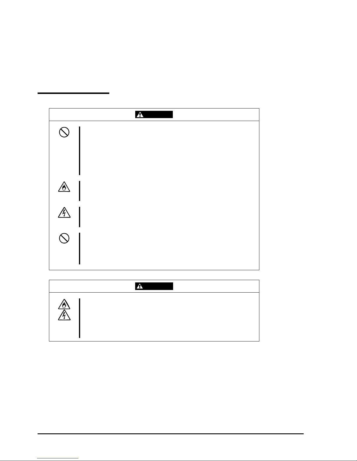
WARNING
Do not use the equipment in an operation where human lives are involved or
high reliability is required.
This equipment is not intended for use in controlling or use with facilities or
systems where human lives are involved or high reliability is required, including
medical devices or nuclear, aerospace, transportation, and traffic control
facilities. the manufacturer assumes no liability for any accidents or damage to
physical assets resulting from the use of this equipment in such systems or
facilities.
Do not continue to use the equipment if you detect smoke, odor, or noise.
If the equipment emits smoke, odor, or noise, immediately flip off the POWER
switch, unplug the cord, and contact your sales agent. There is a risk of a fire.
Do not insert a wire or metal object.
Do not insert a wire or metal objects into a vent or disk drive slot. There is a risk
of an electric shock.
Do not use the equipment in an unsuitable place.
Do not install a server rack in an unsuitable environment.
Other systems also may be affected, and the rack may fall over to cause a fire
or injuries. For details about installation environment and quake-resistant
engineering, see the attached manual or contact your sales agent.
CAUTION
Prevent water or foreign objects from getting into the equipment.
Do not let water or foreign objects (e.g., pins or paper clips) enter the
equipment. There is a risk of a fire, electric shock, and breakdown. When such
things accidentally enter the equipment, immediately turn off the power and
unplug the cord. Contact your sales agent instead of trying to disassemble it
yourself.
Page 15

1-3
Use of Power Supply and Power Cord
WARNING
Do not handle a power plug with a wet hand.
Do not plug/unplug a power cord with a wet hand. There is a risk of an electric
shock.
Do not connect the ground wire to a gas pipe.
Never connect the ground wire to a gas pipe. There is a risk of a gas explosion.
CAUTION
Do not plug the attached cord in a nonconforming outlet.
Use a wall outlet with specified voltage and power type. There is a risk of a fire
or current leakage.
Avoid installing the equipment where you may need an extension cord. If the
cord that does not meet the power specifications, there is a risk of overheating
that could lead to a fire.
Do not plug too many cords in a single outlet.
If the rated current is exceeded, there is a risk of overheating that could lead to
a fire.
Do not plug the cord insecurely.
Insert the plug firmly into an outlet. There is a risk of heat or fire due to poor
contact. If dust settles on the slots and it absorbs moisture, there is also a risk
of heat or fire.
Do not use nonconforming power cords.
AC cord is to spend the thing of the next specifications.
You also have to observe the following prohibitions about handling and
connecting interface cables.
Do not pull on the cord.
Do not pinch the cord.
Do not bend the cord.
Keep chemicals away from the cord.
Do not twist the cord.
Do not tread on the cord.
Do not place any object on the cord.
Do not use cords as bundled.
Do not alter, modify, or repair the cord.
Do not staple the cord.
Do not use any damaged cord. (Replace it with a new one of the same
specifications. For replacement procedures, contact your sales agent.)
Page 16
1-4
Installation, Relocation, Storage and Connection
WARNING
Disconnect the power cord(s) before installing or removing the equipment.
Be sure to power off the equipment and unplug its power cords from the wall
outlet before installation/relocation. All voltage is removed only when the power
cords are unplugged.
CAUTION
Do not install or store the equipment in an unsuitable place.
Install or store the equipment in such a place as specified in this User's Guide.
Avoid the following, or there is a risk of a fire.
a dusty place
a humid place located near a boiler, etc
a place exposed to direct sunlight
an unstable place
Be careful not to hurt your fingers.
Exercise great care not to hurt your fingers on the rail when you
mount/dismount the equipment into/from the rack.
Do not use or store this product in corrosive environment.
Avoid the usage or storage of this product in an environment which may be
exposed to corrosive gases, such as those including but not limited to:
sulfur dioxide, hydrogen sulfide, nitrogen dioxide, chlorine, ammonia and/or
ozone.
Avoid installing this product in a dusty environment or one that may be exposed
to corrosive materials such as sodium chloride and/or sulfur.
Avoid installing this product in an environment which may have excessive metal
flakes or conductive particles in the air.
Such environments may cause corrosion or short circuits within this product,
resulting in not only damage to this product, but may even lead to be a fire
hazard.
If there are any concerns regarding the environment at the planned site of
installation or storage, please contact your sales agent.
Page 17
1-5
CAUTION
Do not connect any interface cable with the power cord of the server plugged to
a power source.
Make sure to power off the server and unplug the power cord from a power
outlet before installing/removing any optional internal device or
connecting/disconnecting any interface cable to/from the server. If the server is
off-powered but its power cord is plugged to a power source, touching an
internal device, cable, or connector may cause an electric shock or a fire
resulted from a short circuit.
Do not use any non-designated interface cable.
Use only interface cables designated by the manufacturer; identif y which
component or connector to attach beforehand. If you use a wrong cable or
make a wrong connection, there is a risk of short-circuit that could lead to a fire.
You also have to observe the following prohibitions about handling and
connecting interface cables:
Do not use any damaged cable connector.
Do not step on the cable.
Do not place any object on the cable.
Do not use the equipment with loose cable connections.
Do not use any damaged cable.
Page 18
1-6
Cleaning and Handling of Internal Devices
WARNING
Do not disassemble, repair, or alter the server.
Unless described herein, never attempt to disassemble, repair, or alter the
equipment. There is a risk of an electric shock or fire as well as malfunction.
Do not look into the DVD-ROM drive.
The DVD-ROM drive uses a laser beam. Do not look or insert a mirror inside
while the system is on. A laser beam is invisible; if your eyes get exposed to it,
there is a risk of losing eyesight.
Do not detach a lithium battery yourself.
This equipment has a lithium battery. Do not detach it yourself. If the battery is
exposed to fire or water, it could explode.
When the lithium battery is running down and the equipment doesn’t work
correctly, contact your sales agent instead of disassembling, replacing or
recharging it yourself.
Disconnect the power plug before cleaning the server.
Make sure to power off the server and disconnect the power plug from a power
outlet before cleaning or installing/removing internal optional devices. Touching
any internal device of the server with its power cord connected to a power
source may cause an electric shock even if the server is off-powered.
Disconnect the power plug from the outlet occasionally and clean the plug with
a dry cloth. Heat will be generated if condensation is formed on a dusty plug,
which may cause a fire.
CAUTION
High temperature
Immediately after powering off the system, system components such as hard
disk may be very hot. Wait for the server to cool down completely before
adding/removing components.
Make sure to complete installation.
Firmly install all power cords, interface cables and/or boards. An incompletely
installed component may cause a contact failure, resulting in fire and/or smoke.
CAUTION
Protect the unused connectors with the protective cap.
The unused power cord connectors are covered with the protective cap to
prevent short circuits and electrical hazards. When removing the power cord
connector from the internal devices, attach the protective cap to the connector.
Failure to follow this warning may cause a fire or an electric shock.
Page 19
1-7
During Operation
CAUTION
Do not pull out a device during operation.
Do not pull out or remove a device while it works. There is a risk of malfunction
and injuries.
Do not touch the equipment when it thunders.
Unplug the equipment when it threatens to thunder. If it starts to thunder before
you unplug the equipment, do not touch the equipment and cables. There is a
risk of a fire or electric shock.
Keep animals away.
Animal’s waste or hair may get inside the equipment to cause a fire or electric
shock.
Do not place any object on top of the server.
The object may fall off to cause injuries, damage to hardware and/or a fire.
Do not leave the DVD tray ejected.
Dust may get in the equipment to cause malfunction. The ejected tray may also
become a cause of injuries.
Page 20
1-8
Rack-mount Model
CAUTION
Do not install the equipment on a nonconforming rack.
Install the equipment on a 19-inch rack conforming to the EIA standard. Do not
use the equipment without a rack or install it on a nonconforming rack. The
equipment may not function properly, and there is a risk of damage to physical
assets or injuries. For suitable racks, contact your sales agent.
Do not attempt to install the server yourself.
To avoid a risk of injuries, users should not attempt to install the equipment into
a rack. Installation should be performed by trained maintenance personnel.
< For Maintenance Personnel Only >
Do not install the equipment in such a manner that its weight is imposed on a
single place.
To distribute the weight, attach stabilizers or install two or more racks. It may
fall down to cause injuries.
Do not assemble parts alone.
It takes at least two people to mount doors and trays to a rack. You may drop
some parts to cause a breakage or injuries.
Do not pull a device out of the rack if it is unstable.
Before pulling out a device, make sure that the rack is fixed (by stabilizers or
quake-resistant engineering).
Do not leave two or more devices pulled out from the rack.
If you pull out two or more devices the rack may fall down. You can only pull out
one device at a time.
Do not install excessive wiring.
To prevent burns, fires, and damage to the equipment, make sure that the rated
load of the power branch circuit is not exceeded. For more information on
installation and wiring of power-related facilities, contact your electrician or local
power company.
Page 21

1-9
For Proper Operation
Observe the following instructions for successful operation of the server. Failure to observe them could lead to
malfunction or breakdown.
Do not use a cellular phone or pager around the equipment. Turn off your cellular phone or pager when you use
the equipment. Their radio waves may cause the equipment to malfunction.
Perform installation in a place where the system can operate correctly. For details, see the separate volume
“User’s Guide (Setup).”
Before turning off the power or ejecting a disk, make sure that the access LED is off.
When you have just turned off the power, wait at least 30 seconds before turning it on again.
Once you have turned on the server, do not turn it off until the full screen logo appears on the screen.
After plugging in the power cord, do not turn on the power of the equipment for 30 seconds.
For safe operation, it is recommended to reboot the OS after duplication is completed.
Before you move the equipment, turn off the power and unplug the cord .
This server shall not assure reproduction of copy-protect CDs using reproduction equipment if such disks do not
comply with CD standards.
Clean the equipment regularly. (For procedures, see Chapter 6.) Regular cleaning is effective in preventing
various types of trouble.
Lightning may cause voltage sag. As a preventive measure, it is recommended to use UPS (uninterruptible power
supply).
This equipment does not support the connection through an UPS serial port (RS-232C) or the control using
PowerChutePlus.
Check and adjust the system clock before operation in the following conditions:
- After transporting the equipment
- After storing the equipment
- After the equipment halt under the conditions which is out of the guranteed environment conditions
(T emperature: 10 to 35
°C, Humidity: 20 to 80%).
Check the system clock once in a month. It is recommended to operate the system clock using a time server
(NTP server) if it is installed on the system which requires high level of time accuracy. If the system clock goes
out of alignment remarkably as time goes by, though the system clock adjustment is performed, contact your
sales agent.
When you store the equipment, keep it under storage environment conditions (Temperature: -10 to 55°C,
Humidity: 20 to 80%, non-condensing).
If Fault Tolerant Server series, the built-in optional devices, and the media set for the backup devices (tape
cartridges) are moved from a cold place to a warm place in a short time, condensation will occur and cause
malfunctions and breakdown when these are used in such state. In order to protect important stored data and
assets, make sure to wait for a sufficient period of time to use the server or components in the operating
environment.
Reference: Length of the time effective at avoiding condensation in winter (more than 10°C differences
between room temperature and atmospheric temperature)
Disk devices: Approximately 2-3 hours
Tape media: Approximately 1 day
Make sure that the optional devices are attachable and connectable to the equipment. There is a risk of
malfunctions that could lead to a breakdown of the equipment even if you could attach and connect.
Make sure that your options are compatible with the system. If you attach any incompatible option, there is a risk
of malfunction that could lead to a breakdown.
It is recommended to use genuine option products purchased from the manufacturer. Some competitors’ products
are compatible with this server. However, servicing for trouble or damage resulting from such a product will be
charged even within the warranty period.
Page 22
1-10
DISPOSAL OF EQUIPMENT AND CONSUMABLES
When you dispose of the main unit, hard disk drives, floppy disks, CD-ROMs, optional boards, etc., you need to
observe your local disposal rules.
Dispose the attached power cable along with the equipment to avoid being used
with other equipment.
For details, ask your municipal office.
IMPORTANT:
For disposal (or replacement) of batteries on the motherboard, consult with your sales agent.
If data remains on the hard disk, backup data cartridges, floppy disks, or other writable media (such as
CD-R and CD-RW), it could be restored and reused by outsiders. The cu stomer is responsible for wiping out
such data before disposal. You need to exercise sufficient care to protect privacy and confidential
information.
Some of the system components have limited lifetime (e.g., cooling fans, built-in batteries, built-in DVD-ROM
drive, floppy disk drive and mouse). For stable operation, it is recommended to replace them regularly. For
lifetime of individual components and replacing procedures, ask your sales agent.
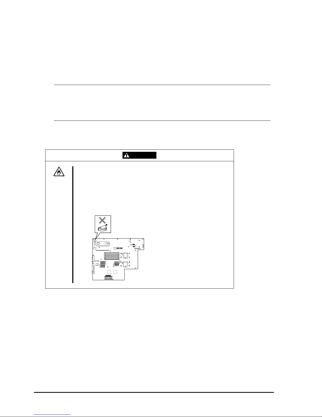
WARNING
Do not detach a lithium battery yourself.
This equipment has a lithium battery. Do not detach it yourself. If the battery is
exposed to fire or water, it could explode.
RISK OF EXPLOSION IF BATTERY IS REPLACED WITH INCORRECT TYPE.
DISPOSE OF USED BATTERIES ACCORDING TO THE INSTRUCTIONS.
When the lithium battery is running down and the equipment doesn’t work
correctly, contact your sales agent instead of disassembling, replacing or
recharging it yourself.
Page 23

1-11
IF SYSTEM TROUBLE IS SUSPECTED
Before sending the equipment for repair, try the following:
1. Check if its power cord and connection cables are attached correctly.
2. See “Error Messages” in Chapter 7 to check if there is a relevant symptom. If yes, take measures as instructed.
3. Certain software programs are required for operation of Fault Tolerant Server series. Check if these programs
are properly installed.
4. Use a commercially available anti-virus program to check the server.
If the problem isn’t solved by the above actions, stop using the server and consult with your sales agent. In this case,
check LED indications of the server and alarm indications on the display, which will serve as helpful information at the
time of repair.
ABOUT REPAIR PARTS
The minimum duration of holding repair parts of this equipment may be different for each country, so contact your sales
representatives.
If the period is not specified, the repair parts are kept for 5 years after di sco nti nuance of the product.
ABOUT OUR WEB SERVICE
Information on Fault Tolerant Server series including modification modules is also available at the manufacturer’s web
site.
Page 24

1-12
Advice for Your Health
Prolonged use of a computer may affect your health. Keep in mind the
following to reduce stresses on your body:
Sit in a good posture
Sit on your chair with your back straight. If the desk height is appropriate,
you will slightly look down at the screen and your forearms will be parallel to
the floor. This “good” work posture can minimize muscle tension caused by
sedentary work.
If you sit in a “bad” posture—for example, sit round-shouldered or with you
face too close to the display—you may easily suffer fatigue or have your
eyesight affected.
Adjust the installation angle of Display
Most types of displays allow you to adjust the angle vertically and
horizontally. This adjustment is ver y important to prevent the reflection of
light as well as to make the screen more comfortable to see. Without this
adjustment, it is difficult to maintain a “good” work posture and may get tired
soon. Be sure to adjust the angle before using the display.
Adjust Brightness and Contrast
Displays allow you to adjust brightness and contrast. Optimum brightness
and contrast vary depending on the individual, age, brightness of the room,
etc; you need to make an adjustment accordingly. If the screen is too bright
or too dark, it is bad for your eyes.
Adjust the installation angle of Keyboard
Some types of keyboards allow you to adjust the angle. If you adjust the
angle to make the keyboard more comfortable to use, you can greatly
reduce stresses on your shoulders, arms, and fingers.
Clean the Equipment
Cleanliness of the equipment is very important not only for reasons of
appearance but also from the viewpoints of function and safety. Especially,
you need to regularly clean the display, which gets unclear due to the
accumulation of dirt.
Take a break when you get tired
If you feel tired, you are recommended to refresh yourself by taking a short
break or doing a light exercise.
Page 25

2-1
Chapter 2
General Description
This chapter describes what you need to know to use the Fault Tolerant Server series. Refer to this chapter when you
want to know about certain components and how to operate them.
Page 26

2-2
STANDARD FEATURES
The Fault Tolerant Server series is the server that has hardware for two servers.
High performance
Intel
®
XeonTM Processor
High-speed Ethernet interface
(1000Mbps/100Mbps/10Mbps supported)
High-speed disk access (SAS (Serial
Attached SCSI))
Expandability
Three slots (low profile (133MHz) x 1, full
size/full height (100MHz) x 2) of PCI-X
bus
Large capacity memory (max: 12 GB)
USB interface
High-reliability Various Features
Graphic accelerator "
ES1000" supported
DVD Combo
Self-diagnosis
Memory monitoring feature (1-bit error
correction/ 2-bit error detection)
Bus parity error detection
Error notification
BIOS password feature
Power On Self-Test (POST)
Test and Diagnosis (T&D) Utility
Management Utilities Maintainability
NEC ESMPRO
Off-line Maintenance Utility
Ready-to-use Easy and Fine Setup
Quick cableless connection: hard disk,
CPU/IO module
EXPRESSBUILDER (system setup
utility)
SETUP (BIOS setup utility)
Fault-tolerant Feature
Redundant modules achieved within a
system
Higher hardware availability by isolation
of failed module
Page 27

2-3
Fault Tolerant Server series is a highly fault-tolerant Windows server that achieves continuous computing operations,
data storage mirror, and continuous network connection. It allows you to run Windows Server 2003-based applications.
Fault Tolerant Server series achieves continuous computing operations for the Windows server and server-based
applications with its redundant CPU processing and redundant memory. It assures data redundancy through duplication
of server data on an independent storage system. These features eliminate server downtime that is usually caused by
network disconnection or trouble with the I/O controller, Ethernet adapter or disk drive, and support operation of the
network and server applications continuously. While being transparent to application software, Fault Tolerant Server
series achieves high fault-tolerance.
Fault Tolerant Server series detects status changes, errors and other events and notifies the Windows Event Log of these
events. If you use an alarm notification tool, you can configure Fault Tolerant Server series to notify you when certain
events occur.
NEC ESMPRO is installed on the system as a server management solution. NEC ESMPRO, a GUI-based management
tool, allows you to monitor, view, and conf igur e Fault Tolerant Server series. This tool also supports both local and
remote management of Fault Tolerant Server series.
Fault Tolerant Server series mainly provides the following advantages:
Highly fault-tolerant processing and I/O subsystems
Fault Tolerant Server series use redundant hardware and software to assure server operation even if one
module suffers trouble with its processor, memory, I/O (including trouble related to the I/O controller), disk
drive, or Ethernet adapter.
Continuous network connection
Fault Tolerant Server series maintains continuous network connection by detecting any trouble with the
network adapter, connection, etc. If trouble occurs, the standby network connection will take over all network
traffic processing and thus securely maintain the network system connection of Fault Tolerant Server series
without losing network traffic or client connection.
Support of multiple network connections
Since Fault Tolerant Server series can support multiple Ethernet connections, you can add network redundant
control or network traffic control.
Industry standard hardware platform
Fault Tolerant Server series uses IA (Intel Architecture)-based system hardware.
No need to modify applications
You can run Windows Server 2003-compliant applications on Fault Tolerant Server series. Thus, unlike other
highly fault-tolerant products, special API or scripts are not necessary.
Automati c mi rroring
Fault Tolerant Server series automatically maintains data as the current data.
Automatic detection and notification of faults
Fault Tolerant Server series detects and sorts out all events such as general status changes and faults, and
notifies Windows Event Log of these events.
Transparent migration
Fault Tolerant Server series constantly monito rs events. If trouble occurs on Fault Tolerant Server series’
server module, it will transparently use a redundant module of the failed module. This feature maintains data
and user access without losing application service.
Automatic reconfiguration
When the failed module restarts after the trouble is corrected, Fault Tolerant Server series will perform
reconfiguration automatically, and if necessary, resynchronize the affected modules. Reconfiguration can
include CPU processing (e.g., CPU memory), server's operating system (and related applications), and system
data stored on the hard disks. In most cases, Fault Tolerant Server series automatically restores redundancy of
the server modules after recovery.
Page 28
2-4
Local and remote management
Fault Tolerant Server series uses NEC ESMPRO as a server management tool. This tool uses a GUI that
enables monitoring and setting of Fault Tolerant Server series. NEC ESMPRO can be used both locally and
remotely on work station PCs or server PCs.
Event notification function
When trouble or other events are detected on Fault Tolerant Server series, they will be notified to Windows
Event Log and saved. Therefore, you can view the log items locally or remotely by a usual Windows
procedure. Since an Fault Tolerant Server series events use unique IDs, they are easy to distinguish.
In-service repairing
You can repair or replace a failed module even if Fault Tolerant Server series is operating.
Partition structure
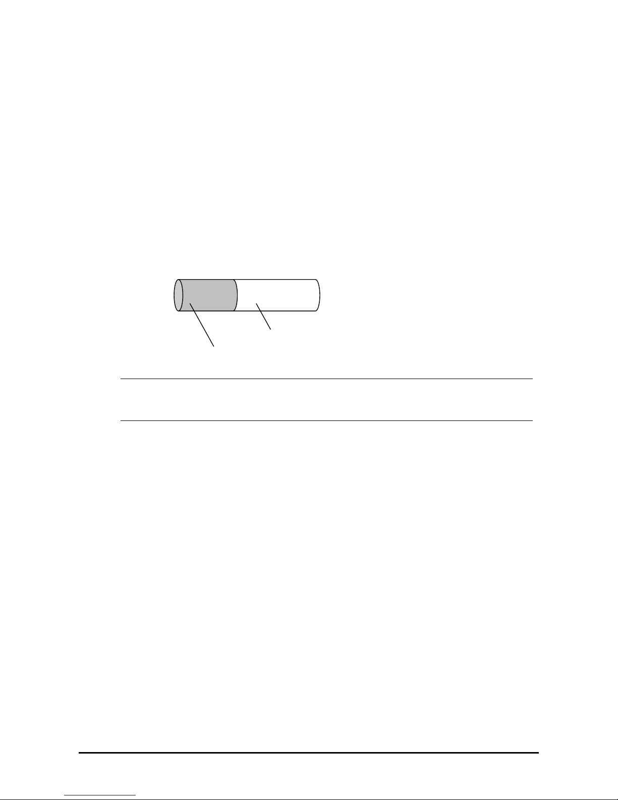
On this product, the first logical drive will be in the following state when the setup by EXPRESSBUILDER is
complete:
* The size varies depending on the specification at setup.
CHECK:
The partition for operating system is not mirrored at the time of EXPRESSBUILDER setup completion.
Mirror the partition separately.
Windows OS and media
The Windows OS media used on Fault Tolerant Server series are not specifically processed for it. The
standard operating methods of Windows are same as general.
Partition for operating system (*)
Free area (*)
Page 29
2-5
HOW THE OPERATING SYSTEM SEES THE CPU MODULES
On Fault Tolerant Server series, the CPU modules are redundantly con figured and all processors installed on this serve r
are shown.
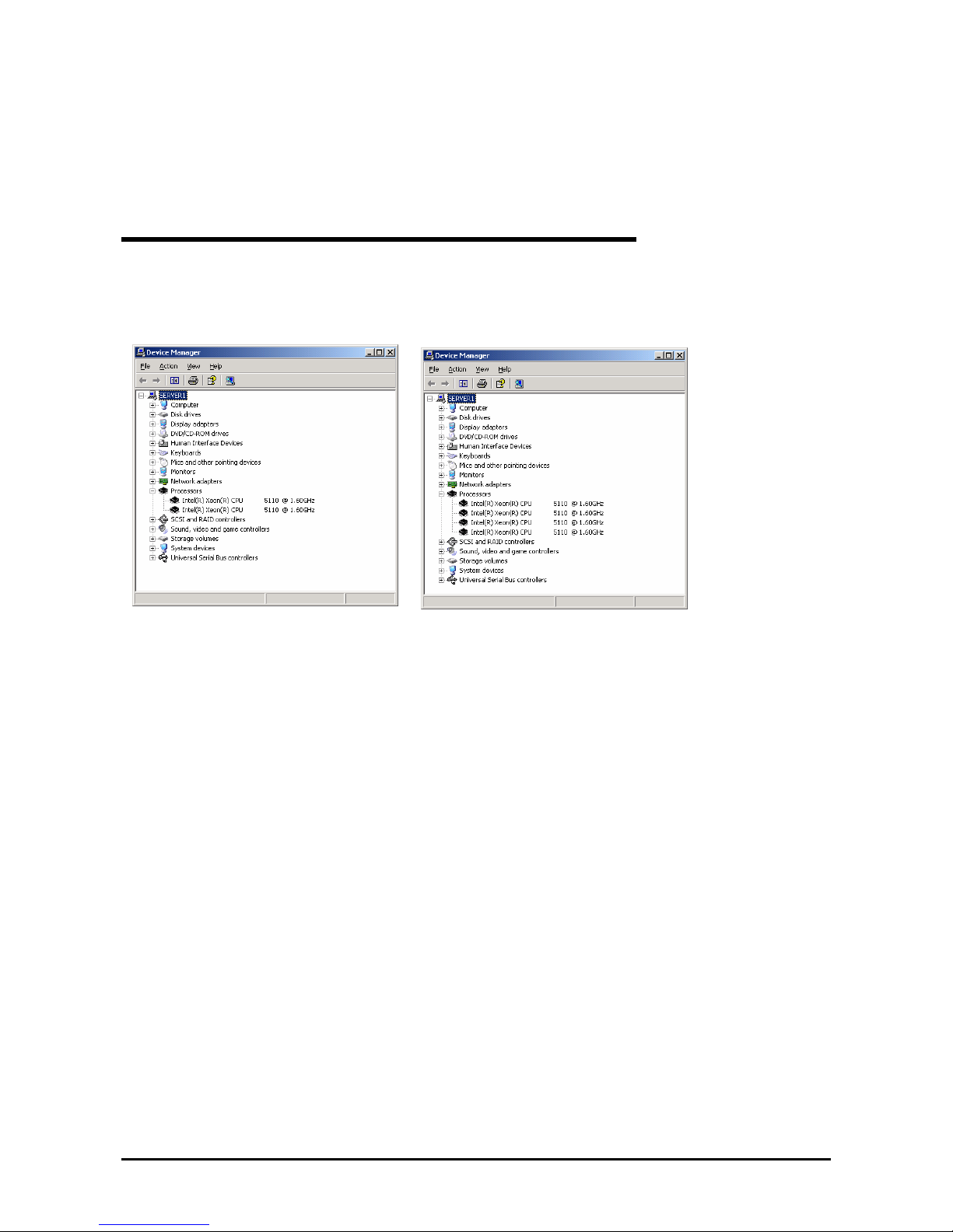
How CPU modules appear on Device Manager
As shown below, logical CPUs are displayed as many as there are. For multi-processor, the number of displayed CPUs
is the number of physical processors on one CPU/IO module multiplied by the number of cores per processor.
System with one CPU (Dual-Core) System with two CPUs (Dual-Core)
Page 30
2-6
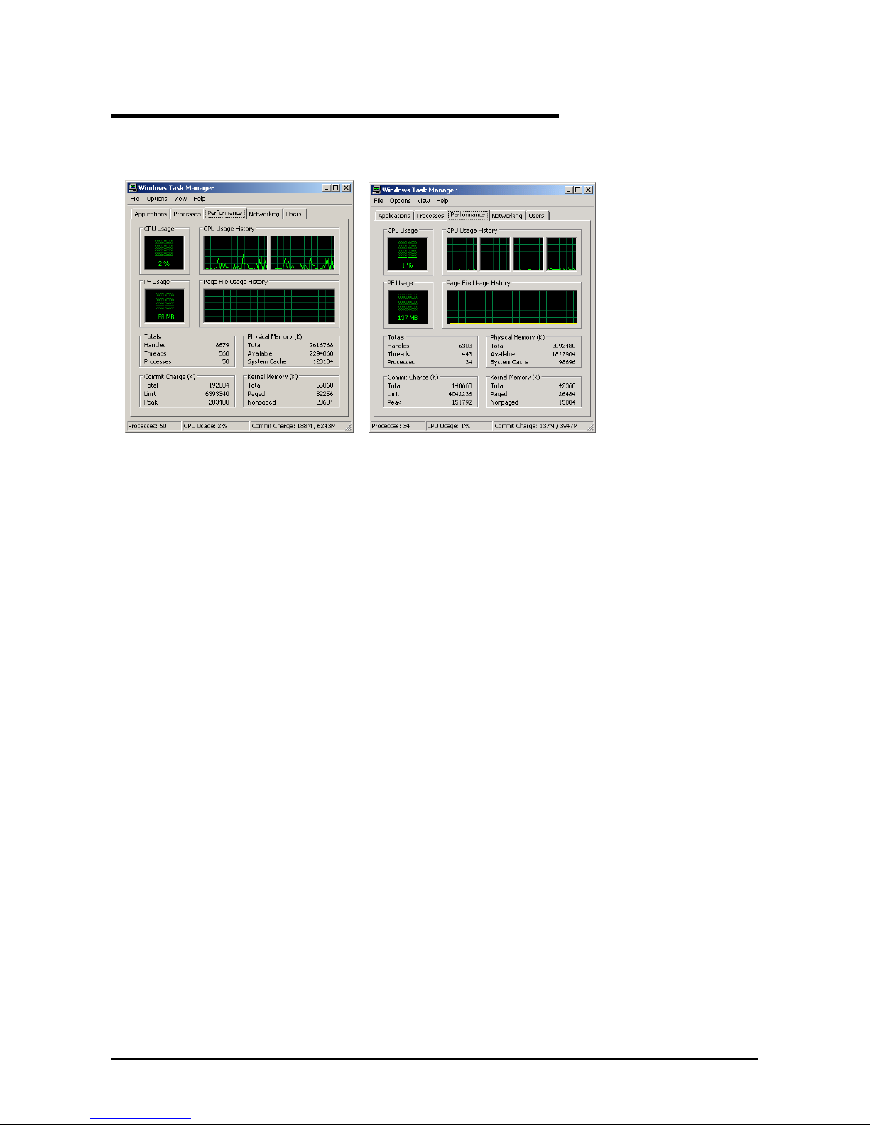
How CPU modules appear on Task Manager
As with Device Manager, logical CPUs are displayed as many as there are.
System with one CPU (Dual-Core)
System with two CPUs (Dual-Core)
Page 31
2-7
NAMES AND FUNCTIONS OF COMPONENTS
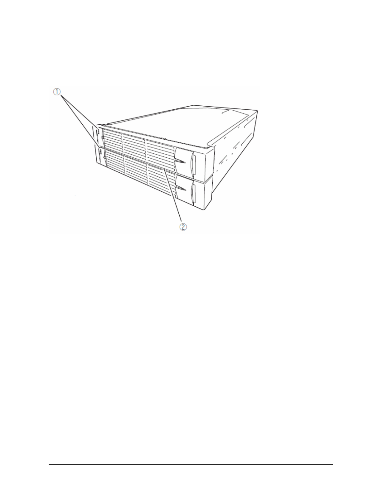
Names and functions of components are shown below:
(1) LEDs
For more information see the description on the front view (page 2-8).
(2) Front bezel
The cover to protect devices in the front.
Page 32
2-8
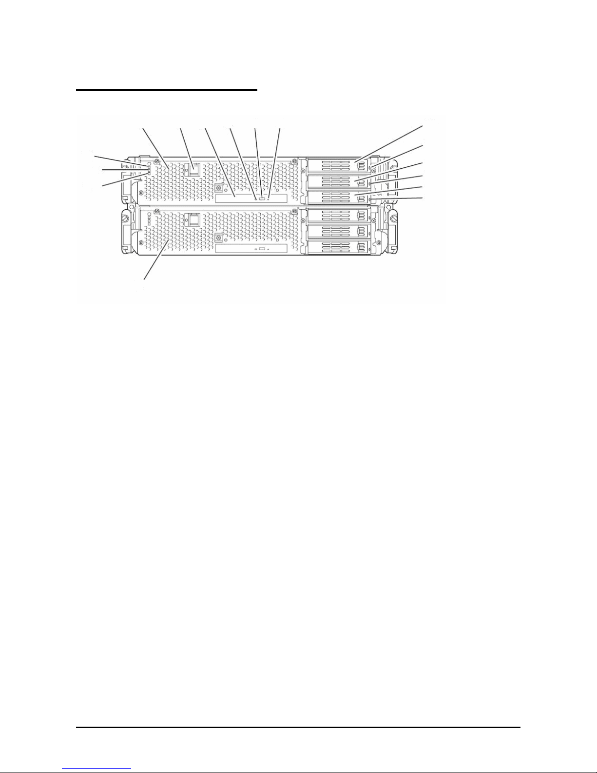
Front View
(1) CPU/IO module 0
This is a module with a set of CPU (processor), memory (DIMM), PCI board, cooling fan unit, and hard disk drive.
(2) POWER switch
This switch is used to power on/off the server. The in-built LED illuminates for the primary CPU/IO module,
showing that it is primary. (The secondary POWER LED (off) cannot be used. If the switch is pressed once, the
server is powered on. If the switch is pressed again, the server is powered off. If the switch is pressed for more than 4
seconds, the server is forcibly shut down.
(3) DVD-ROM drive
This device is used to read data from CD-ROMs.
(4) DISK ACCESS LED
This LED illuminates when the set optical disks are accessed.
(5) T r ay eject button
This button ejects the tray.
(6) Forcible eject hole
This is the hole for forcibly eject by inserting a metal pin.
(7) Hard disk drive bay
This is the bay to mount the hard disk drive. The number after the parenthesized number indicates a slot number.
With the front bezel removed
(11)
(10)-1
(10)-2
(1) (2) (3)
(4) (5) (6)
(7)-3
(8)
(7)-2
(8)
(7)-1
(8)
(9)
Page 33

2-9
(8) CPU/IO module DISK ACCESS LED (green/amber)
This LED illuminates in green when the internal hard disk drives are accessed. If any internal hard disk drive is
failing, the LED illuminates in amber.
(9) CPU/IO module 1
This is a module with a set of CPU (processor), memory (DIMM), PCI board, cooling fan unit, and hard disk drive.
(10)-1 CPU/IO module status LED 1 (amber)
This LED indicates the status of the CPU/IO module. When the module is successfully running, the LED is powered
off. If a module has a problem, the LED illuminates in amber.
(10)-2 CPU/IO module status LED 2 (green)
This LED indicates the status of the CPU/IO module. When both of the CPU/IO modules are running, the LED
illuminates in green. When one of the modules is running, the LED blinks in green or is powered off.
(11) CPU/IO module POWER LED (green)
When the power is turned on, the LED illuminates in green.
Page 34
2-10
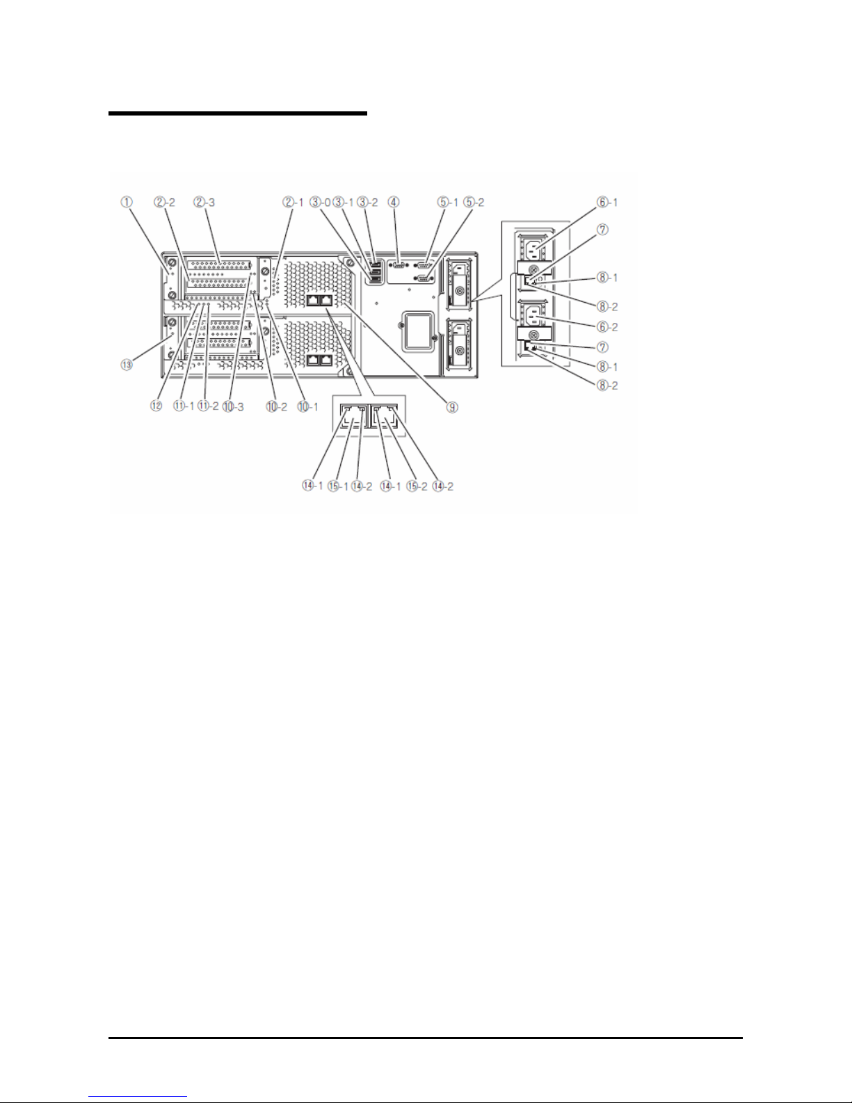
Rear View
(1) CPU/IO module 0
This is a module with a set of CPU (processor), memory (DIMM), PCI board, and cooling fan unit.
(2)-1, 2, 3 PCI-X slots 1, 2, 3
(2)-1 is the slot on which the low profile type PCI board is mounted (64 bit 133MHz 3.3V PCI-X).
(2)-2, 3 are the slots on which the FullSize and FullHight types PCI boards are mounted (64bit 100MHz 3.3V
PCI-X).
(3)-0, 1, 2 USB connector 0, 1, 2
This connector is connected with the system that supports the USB2.0 interface.
(4) Monitor connector
This connector is used to connect a display device.
(5)-1, 2 serial port 1, 2 connector
This connector is connected to the system with the serial interface. It cannot be used for this server.
(6)-1 AC inlet A connector
A power cord is connected to this socket (for the CPU/IO module 0). If you want make the CPU/IO module 0
primary, connect a power cord to this inlet first.
(6)-2 AC inlet B connector
A power cord is connected to this socket (for the CPU/IO module 1). If you want to make the CPU/IO module 1
primary, connect a power cord to this inlet first.
(7) LAN connector (VTM)
Use only for Active Upgrade.
(8)-1 LINK/ACT LED (VTM)
This LED indicates the access status of LAN (VTM).
(8)-2 Speed LED (VTM)
This LED indicates the transfer speed of LAN(VTM).
Page 35

2-11
(9) DUMP (NMI) switch
This is the switch to perform a memory dump.
TIPS:
Press the DUMP switch on the primary CPU/IO module, whose POWER LED has been blinking, for four to eight
seconds. Use something sharp, such as curved clips to press the DUMP switch on CPU/IO module 1.
(10)-1, 2 PCI slot status LED (Slot 1, 2, 3)
This is the LED to display the status of the PCI slot. The status is shown by the display combination of the 2 LEDs.
(11)-1 CPU/IO module status LED 1 (amber)
This LED indicates the status of the CPU/IO module. When the module is successfully running, the LED is powered
off. If a module has a problem, the LED illuminates in amber.
(11)-2 CPU/IO module status LED 2 (green)
This LED indicates the status of the CPU/IO module. When both modules are operating, the LED illuminates in
green. When one module is operating, the LED blinks in green or is powered off.
(12) CPU/IO module POWER LED (green)
This Led illuminates in green when the system is powered on.
(13) CPU/IO module 1
This is a module with a set of CPU (processor), memory (DIMM), PCI board, and cooling fan unit.
(14)-1 LINK/ACT LED
This is the LED to indicates the access status of the LAN connector.
(14)-2 Speed LED
The LED indicates the transfer speed of the LAN connector.
(15)-1, 2 LAN connector 1, 2
This is the connector to support 1000BASE-T/100BASE-TX/10BASE-T. This is connected to the network system on
LAN.
Page 36
2-12
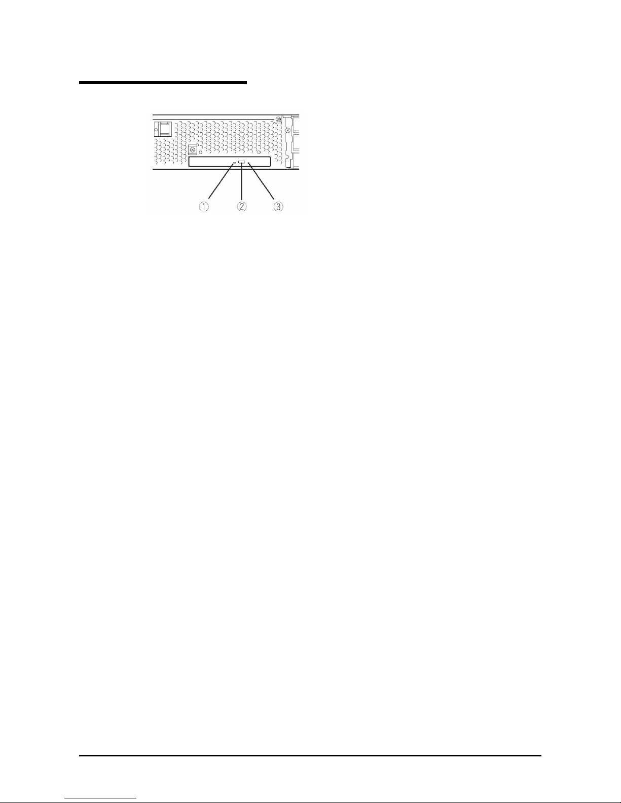
DVD-ROM drive
(1) Status LED
An LED that stays on while the loaded CD-ROM is accessed.
(2) Tray eject button
A button for ejecting the tray.
(3) Manual release hole
When the eject button does not work, insert a metal pin into this hole to forcefully eject the tray.
Page 37
2-13
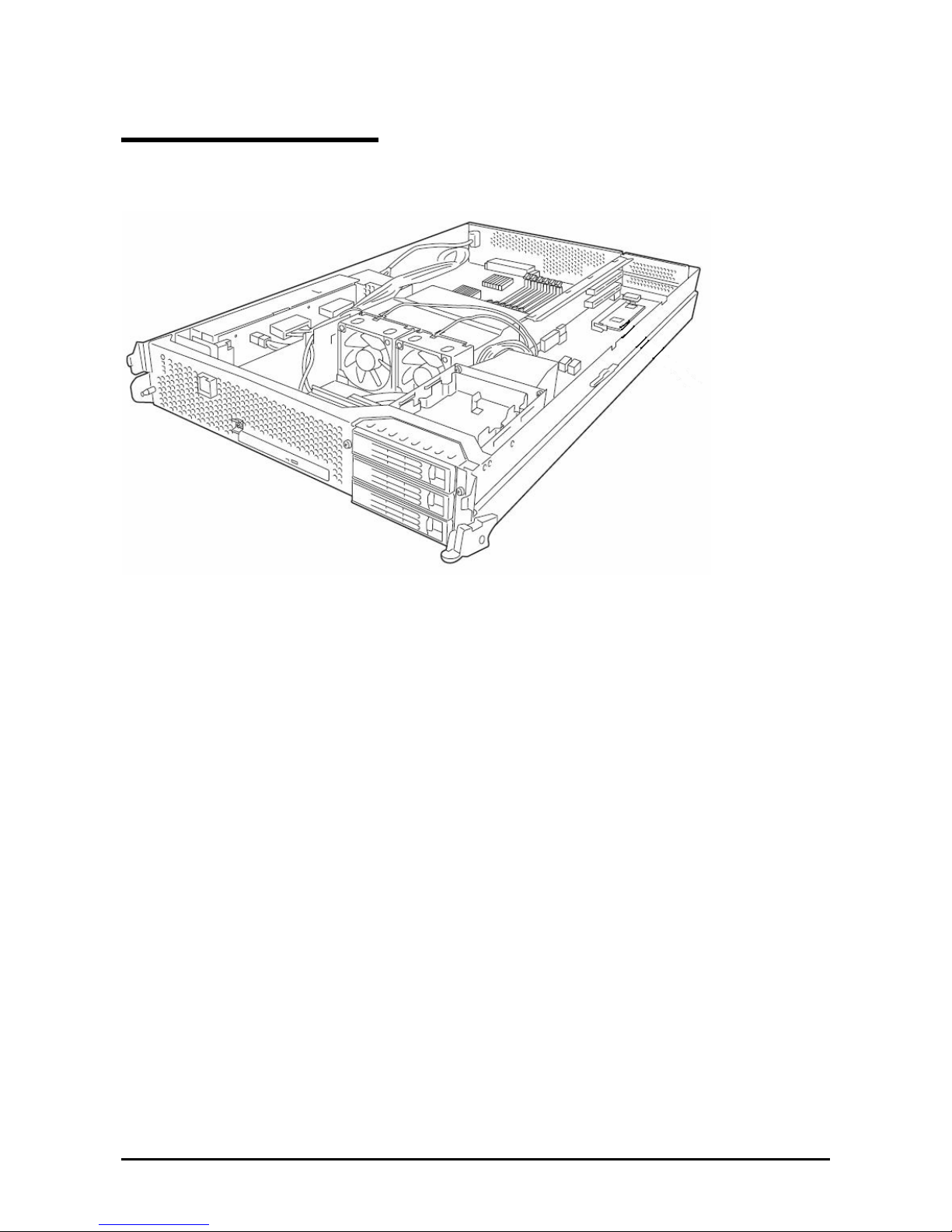
CPU/IO Module
CPU/IO module
Page 38
2-14
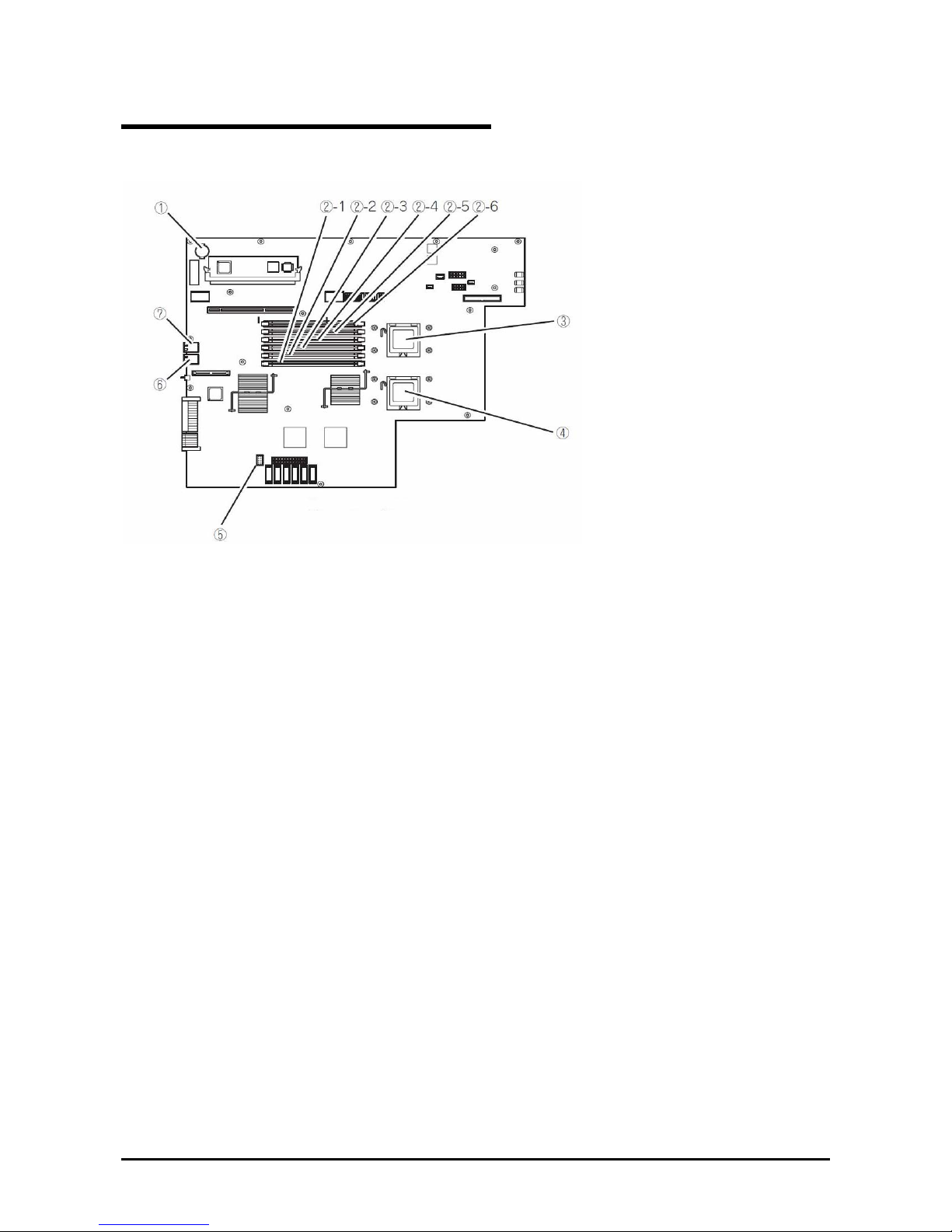
Mother Board
(1) Lithium battery
(2) DIMM slot ((2)-1 from the bottom)
(2)-1 DIMM CH0 Slot 0
(2)-2 DIMM CH0 Slot 1
(2)-3 DIMM CH0 Slot 2
(2)-4 DIMM CH1 Slot 0
(2)-5 DIMM CH1 Slot 1
(2)-6 DIMM CH1 Slot 2
(3) Processor 0 socket (CPU0)
(4) Processor 1 socket (CPU1)
(5) Jumper switch for clearing CMOS/password
(6) LAN 2 connector
(7) LAN 1 connector
CPU/IO module mother board
Page 39

2-15
LEDs
POWER LED
The POWER switch of the CPU/IO module has an in-built LED. If the AC power is supplied, the LED of the primary
POWER switch illuminates (only the primary POWER switch functions). Also, the CPU/IO module has the POWER
LED to show the status of the module power status.
CPU/IO Module POWER LED
LED indication Description Action
Not on Power supply is off. Check that the status LED 1
on both CPU/IO modules is
powered off, and then press
the POWER LED to power on
the system.
On Power supply is on.
CPU/IO Module Status LED 1, 2
There are two kinds of LEDs that indicate the module status on the front and back sides of the CPU/IO module. The
display combination of the two LEDs indicates the CPU/IO module status.
Status
LED1
Status LED2 Description Action
Not on Power supply is off.
When the system is starting, the
initialization process is performed.
Wait for a while; the LED
will illuminate in green.
Blinking in
green
If the OS is running, duplex
configuration is not made for one
of the components in the CPU/IO
modules.
Check that the cable is
firmly connected. If the LED
does not illuminate in green
after a while, record the
status LED status, and
contact a maintenance
service company.
Not on
Green The device is duplexed and
running normally.
After the AC power is supplied, the
device running in the standby
power mode is being initialized.
Wait for a while. The status
LED 1 will be powered off,
and the POWER switch will
be enabled.
When the system is starting, the
initialization process is performed.
Wait for a while; the status
LED 1 is powered off.
Amber
Not on
When the OS is running, the
CPU/IO module has a problem.
Check that the cable is
firmly connected. If the LED
does not illuminate in green
after a while, record the
status LED status, and
contact a maintenance
service company.
Page 40
2-16
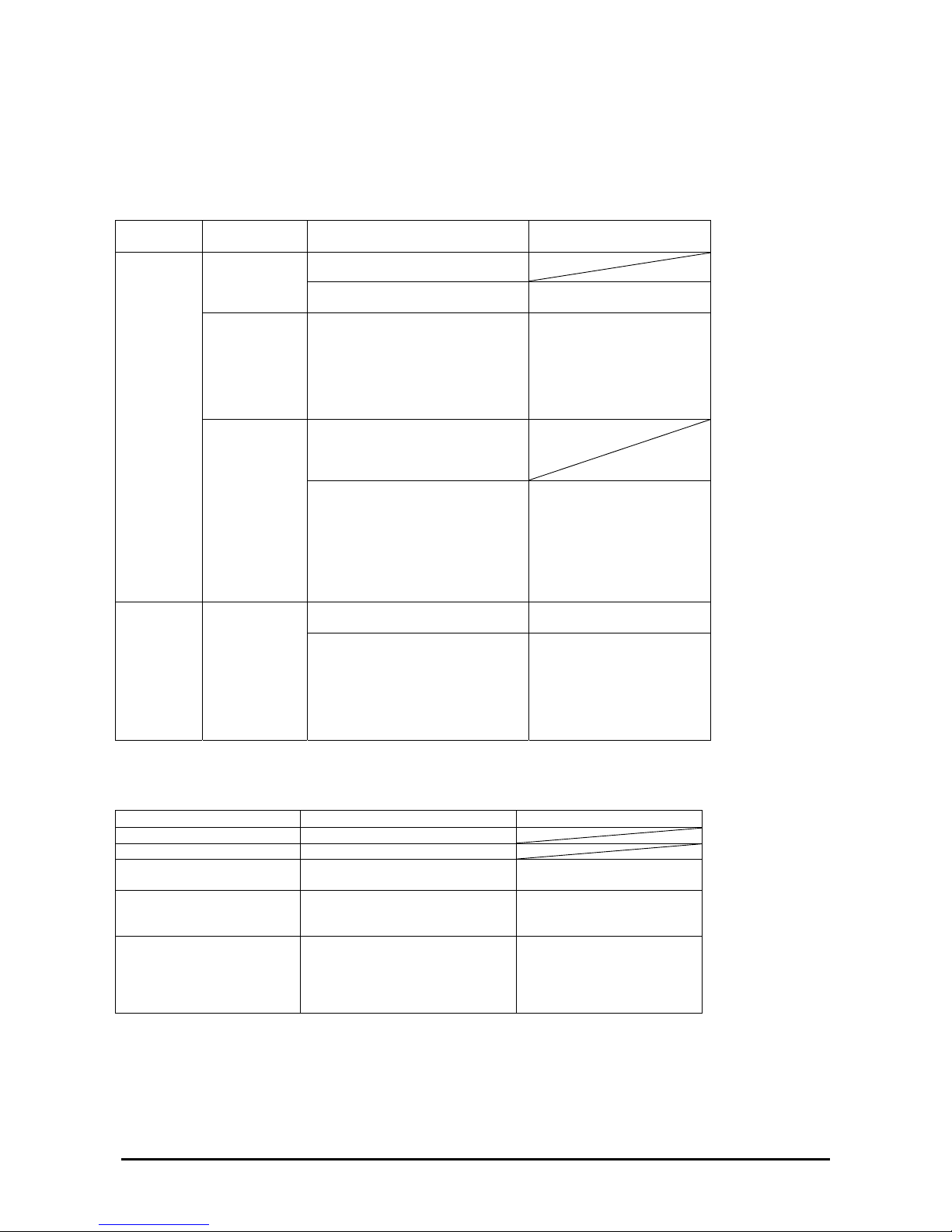
PCI Slot status LED 1, 2
There are two kinds of LEDs that indicate the PCI slot status on the back of the CPU/IO module. The PCI slot status is
indicated by the display combination of the two LEDs.
Status
LED1
Status LED2 Description Action
Power supply is off. Not on
When the system is starting, the
initialization process is performed.
Wait for a while; the LED
illuminates in white.
Blinking in
white
If the OS is running, it is in the
Simplex mode, and the PCI slot of
the other CPU/IO module is
degenerated.
Check that the cable is
firmly connected. If the LED
does not illuminate in white
after a while, record the
status LED status, and
contact a maintenance
service company.
If the PCI slot status LED 2 of the
other CPU/IO module is on, the
device is successfully running in
the Duplex mode.
Not on
White
If the PCI slot status LED 2 of the
other CPU/IO module is lit, the
cable may be disconnected, or the
option PCI board of the slot has a
problem.
Check that the cable is
connected securely. If the
PCI slot status LED 2 of the
other CPU/IO module does
not illuminate white, record
the status of the status LED,
and call your maintenance
service company.
When the system is starting, the
initialization process is performed.
Wait for a while; the status
LED 1 is powered off.
Amber
Not on
When the OS is running;
1) The optional PCI board of the
slot has a problem.
2) The CPU/IO module has a
problem.
Check that the cable is
firmly connected. If the LED
does not illuminate in white
after a while, record the
status LED status, and
contact a maintenance
service company.
Hard Disk Drive LED
Hard Disk LED Description Action
Not on The disk is in the idle state.
Green Accessing the disk
Amber Disk failure Contact a maintenance
service company.
Blinking in amber
(Illuminate in green when
accessing the disk)
The mirror of the disk is
disconnected.
Perform mirroring.
Blinking in green and amber
in turn
The hard disk drive configuration
(rebuild) is on going.
Wait for a while; the LED
blinks in green after rebuild
finishes. If the rebuild fails,
the LED illuminates in
amber.
Page 41

2-17
Access LED on the DVD-ROM drive
This LED illuminates when the installed CD-ROM is being accessed.
LAN Connector LED
• LINK/ACT LED
The LINK/ACT LED shows the status of a standard network port. It is green if power is supplied to the main unit
and hub, and they are connected correctly (“LINK”). It blinks green while the network port sends or receives data
(ACT).
When the LED does not illuminate during “LINK,” check the condition and connection of network cables. If there
is nothing wrong with the cables, a defect is suspected in the network (LAN) controller. In this case, contact your
sales agent.
• Speed LED
This LED indicates the network interface of the communication mode used by a network port.
1000BASE-T and 100BASE-TX are the supported LAN port types. When this LED illuminates in amber, the port is
operating on 1000BASE-T. When the LED illuminates in green, the port is operating on 100BASE-TX.
Page 42
2-18
BASIC OPERATION
This section describes basic operation procedures of Fault Tolerant Server series.
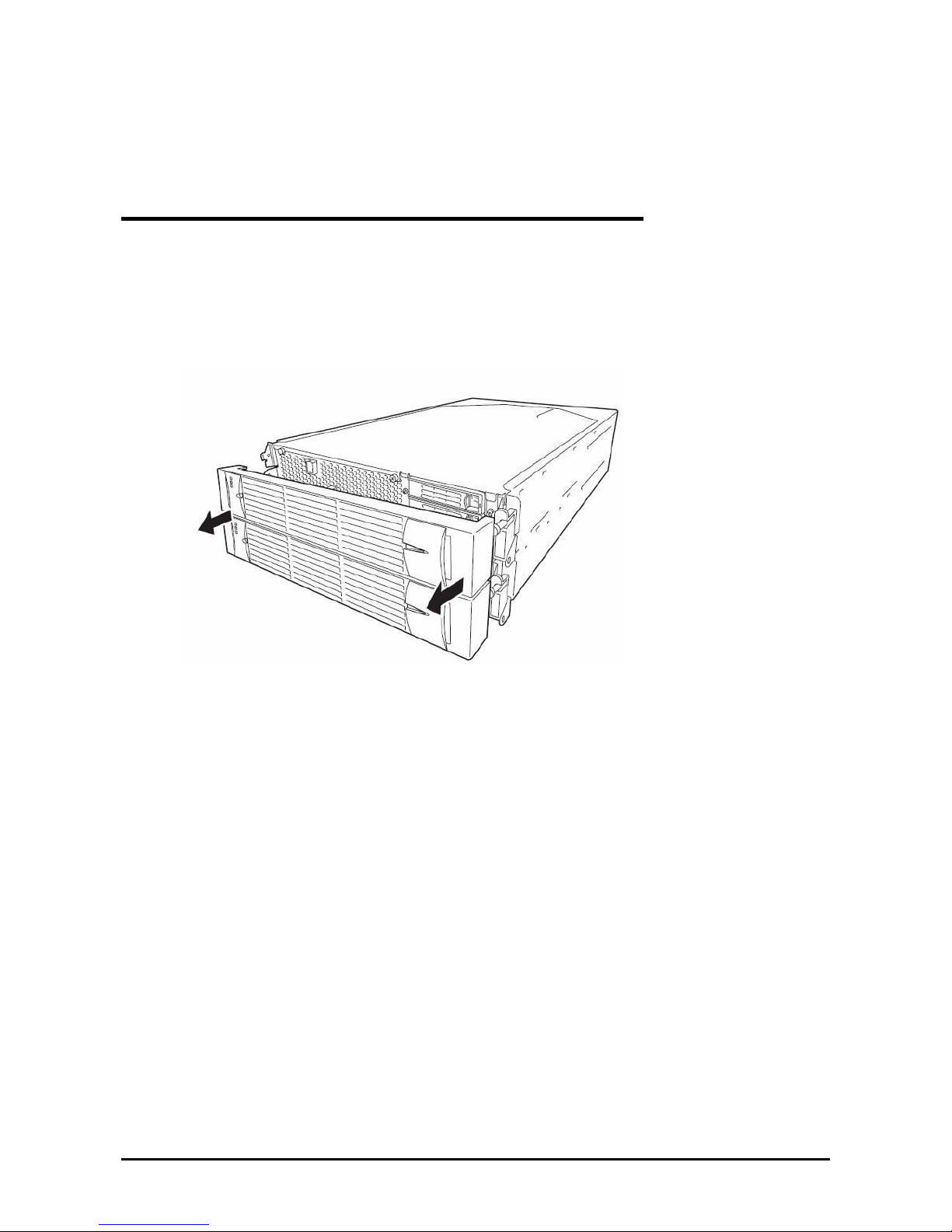
Installing/removing the front bezel
When you power on/off the server, handle the DVD-ROM drive, or remove/install a hard disk drive or
CPU/IO module, remove the front bezel.
(1) Lightly hold the front bezel and pull it out.
When installing the front bezel, install it while holding both sides of the front bezel.
Page 43
2-19
Power ON
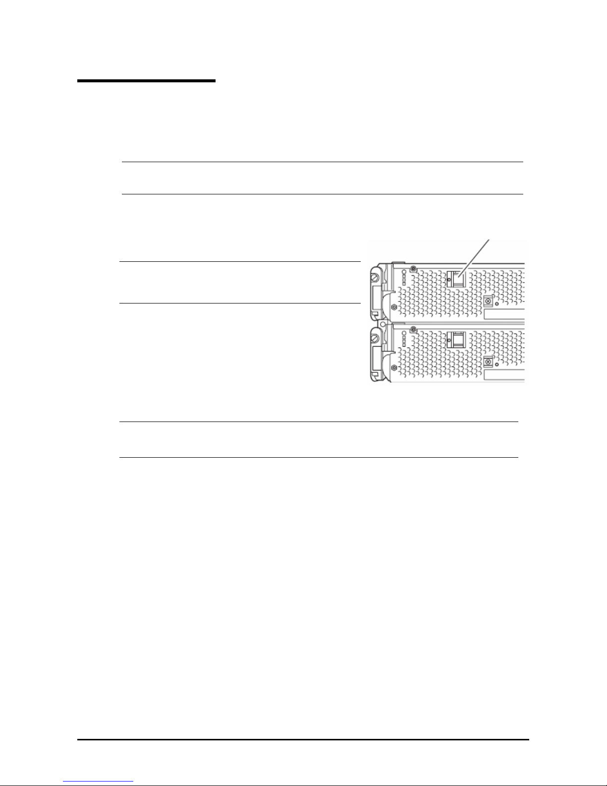
To power on Fault Tolerant Server series, press the POWER switch (the one whose in-built LED is illuminating).
Follow the steps below to turn on the power.
1. Power on the display unit and other peripheral devices connected to the server.
CHECK:
If the power cord is connected to a power controller like a UPS, make sure that it is powered on.
2. Remove the front bezel.
3. Press the power switch located on the front of the front panel.
After a while, a full-screen logo will appear on the screen.
IMPORTANT:
Do not turn off the power before you see the logo and a
character below the logo.
While the logo is displayed on the screen, Fault Tolerant Server
series is performing a power-on self test (POST) to check itself.
For details, see "POST Check" described later in this chapter. Upon the completion of POST, Windows Server
2003 will start.
CHECK:
If the server finds errors during POST, it will interrupt POST and display the error message. See Chapter
7.
Power switch
Page 44

2-20
Power OFF
Follow the steps below to turn off the power. If Fault Tolerant Server series is plugged to a UPS, see manuals included
with the UPS or the application that controls the UPS.
1. Perform a normal shutdown from Windows Server 2003.
The system will be powered off automatically. (Note: the POWER switch on the primary side will remain
illuminating when AC power is supplied.)
2. Power off all peripheral devices.
POST Check
POST (power-on self test) is a self-test function stored on the motherboard of Fault Tolerant Server series.
When you power on the server, POST will start automatically to check the motherboard, ECC memory modules,
CPU/IO modules, keyboard, mouse, etc. It also shows startup messages for various BIOS setup utilities.
According to the factory default settings, a full-screen logo appears on the display while POST is being performed. (To
view POST’s details, press Esc.)
TIPS:
You can view POST details from the beginning without the need to press Esc when the BIOS menu is
displayed: select [System Configuration] - [Advanced], and set [Boot-time Diagnostic Screen] to "Enabled"
(see Chapter 4).
You can view the test items and details from a management PC where NEC ESMPRO Manager is installed.
You do not always need to check POST details. You will need to check messages when:
You install a new Fault Tolerant Server series.
A failure is suspected.
You hear several beeps between the time of the power-on and OS start-up.
The display unit shows an error message.
Page 45

2-21
Flow of POST
This section walks you through how POST is performed.
1. When you power on the system, one selected CPU/IO module will start up.
POST will be performed on this selected CPU/IO module.
2. Memory check starts.
A message appears at the upper left of the screen to show that the basic and expanded memories are being
counted. The memory check may take a few minutes to complete depending on the server’s memory size.
Likewise, it may take about one minute for the screen to appear when the server is rebooted.
3. The server starts processor check, IO check, and initialization.
Several messages appear: they show the ID of the selected CPU/IO modules, information on the processor,
detection of the keyboard and mouse, etc.
4. A message appears at the lower left of the screen, prompting for startup of the BIOS setup utility “SETUP.”
Press <F2> to enter SETUP
You will need to start it when you want to modify the configuration for using the server. Unless this message
appears together with an error message, you do not need to start the utility to modify the configuration. (If you
wait for a few seconds, POST will go on automatically.)
To start the SETUP utility, press F2 while the above message is displayed. For setting and parameter
functions, see the section of BIOS setup.
When SETUP is completed, the server will reboot itself automatically and perform POST.
5. A m essage appears prompting for startup of SAS BIOS setup utility.
When a built-in SAS controller is detected, a message will appear prompting for startup of SAS BIOS setup
utility. (If you wait for a few seconds, POST will go on automatically.)
If you press Ctrl + A, the SAS BIOS setup utility will start. However, you usually do not need to use the
setup utility. For setting and parameter functions, see “SAS BIOS” (page 4-33).
When SETUP is complete, the server will reboot automatically and perform POST from the start again.
6. The screen shows the ID numbers of the connected disk drive.
7. Upon completion of POST, the password entry screen appears prior to OS startup.
The password entry screen will appear after the normal termination of POST only if you have set a password
in the BIOS setup utility “SETUP.”
You can enter a password up to three times. If you enter an incorrect password three times, the startup will be
unsuccessful. In this case, turn off the power and then turn it on again after waiting 30 seconds to boot the
server.
IMPORTANT:
Do not set a password before installing the OS.
8. Upon completion of POST, the OS will start up.
Behavior at Occurrence of Error
If POST or OS startup does not finish normally, the server will reboot itself automatically.
At the time of reboot, it will select the other CPU/IO module and run POST or OS startup.
Page 46

2-22
In this manner, the server retries POST or OS startup with different combinations of CPU/IO modules. If POST does
not finish normally with any combinations, the server will stop with the state of DC OFF or Post end with an error
message displayed.
While performing retries, the server displays or registers the error types.
For details of error messages, see Chapter 7 “Troubleshooting.”
POST Error Messages
When the server detects an error during POST, it will notify you of the occurrence in the following manners:
Displays an error message on the display unit.
These notification methods are described in “POST Error Messages” (Page 7-4).
IMPORTANT:
Before you contact your sales agent, write down the error messages. They will serve as helpful information at the
time of maintenance.
CPU/IO Module Status
The CPU/IO module (0 or 1) started first is managed as primary, and the module started later is managed as secondary.
If one CPU/IO module is disconnected because of the failure and others, the other module becomes primary.
The CPU/IO module to be started first is selected depending on the primary/secondary status of modules when the
server was shut down the last time.
The following devices are connected to the primary CPU/IO module by the hardware switch, although those can be
connected to both CPU/IO modules 0 and 1. When one CPU/IO module is disconnected because of a failure, those are
switched to the other module automatically and continue operating.
VGA (display)
USB device (keyboard, mouse, floppy disk drive)
TIPS:
As for DVD-ROM drive, the DVD-ROM drive of both CPU/IO modules 0 and 1 can be accessed. If one CPU/IO
module is disconnected because of the failure, only the DVD-ROM of the other module can be accessed
.
IMPORTANT:
If the optional floppy disk drive is connected, the drive letter may change from A to B by switching
CPU/IO modules.
The drive letter of the DVD-ROM drive is allocated again automatically. The letter which is not used is
allocated to the drive in the order of D to Z. If you want to set the fixed drive letter to the DVD-ROM, specify
the drive letter which is not allocated in the order of D to Z after setting the hard disk drive letter.
Page 47

2-23
Floppy Disk Drive (Option)
If you want to use a floppy disk drive with this server, connect USB FDD UNIT, which are available optionally to a
USB connector.
This server supports 3.5-inch 2HD (1.44 MB) and 2DD (720KB) floppy disks.
IMPORTANT:
When using a USB floppy disk drive, the access to the floppy disk is delayed on rare occasions if the display graphic
load is high because a moving picture is being played. In such a case, retry the operation w ith the floppy disk inside the
floppy disk drive.
Insert/Remove Floppy Disk
Before inserting a floppy disk into the drive, make sure that Fault Tolerant Server series is on (the POWER LED
illuminates).
Insert a floppy disk into the drive firmly until it snaps in place. The eject button of the drive is then raised slightly.
CHECK:
You cannot use 1.2 MB-formatted disks.
If you insert an unformatted disk, you will see a message that the disk cannot be read or that needs
formatting. To format a floppy disk, see your OS manual.
If you power on or restart Fault Tolerant Server series with a floppy disk left in the drive, the server will access
the floppy disk to start the system. Unless a system exits on the FD, the server will be unable to start.
To remove a floppy disk from the drive, press the eject button.
CHECK:
Before removing a floppy disk, make sure that the floppy disk access LED is off. If you eject a
floppy disk while the LED is on, the stored data could be damaged.
When using a USB floppy disk drive, the access to the floppy disk is delayed on rare occasions if the
display graphic load is high because a moving picture is being played. In such a case, retry the
operation with the floppy disk inside the flo p py dis k drive.
Use of Floppy Disk
You may need to store important data on floppy disks. Since the floppy disk is a very delicate mediu m, you must handle
it with extra care:
Push the floppy disk gently into place.
Attach the label on a proper position.
Do not use a pencil or ballpoint pen to write on the floppy disk.
Do not open the protective shutter.
Do not use the floppy disk in a dusty place.
Do not place anything on the floppy disk.
Do not leave the floppy disk in a place that is subject to direct sunlight or high temperatures (e.g., near a
heater).
Keep away from cigarette smoke.
Do not leave the floppy disk near water or chemicals.
Keep away from magnetic objects.
Do not clip disks. Be careful not to drop.
Page 48
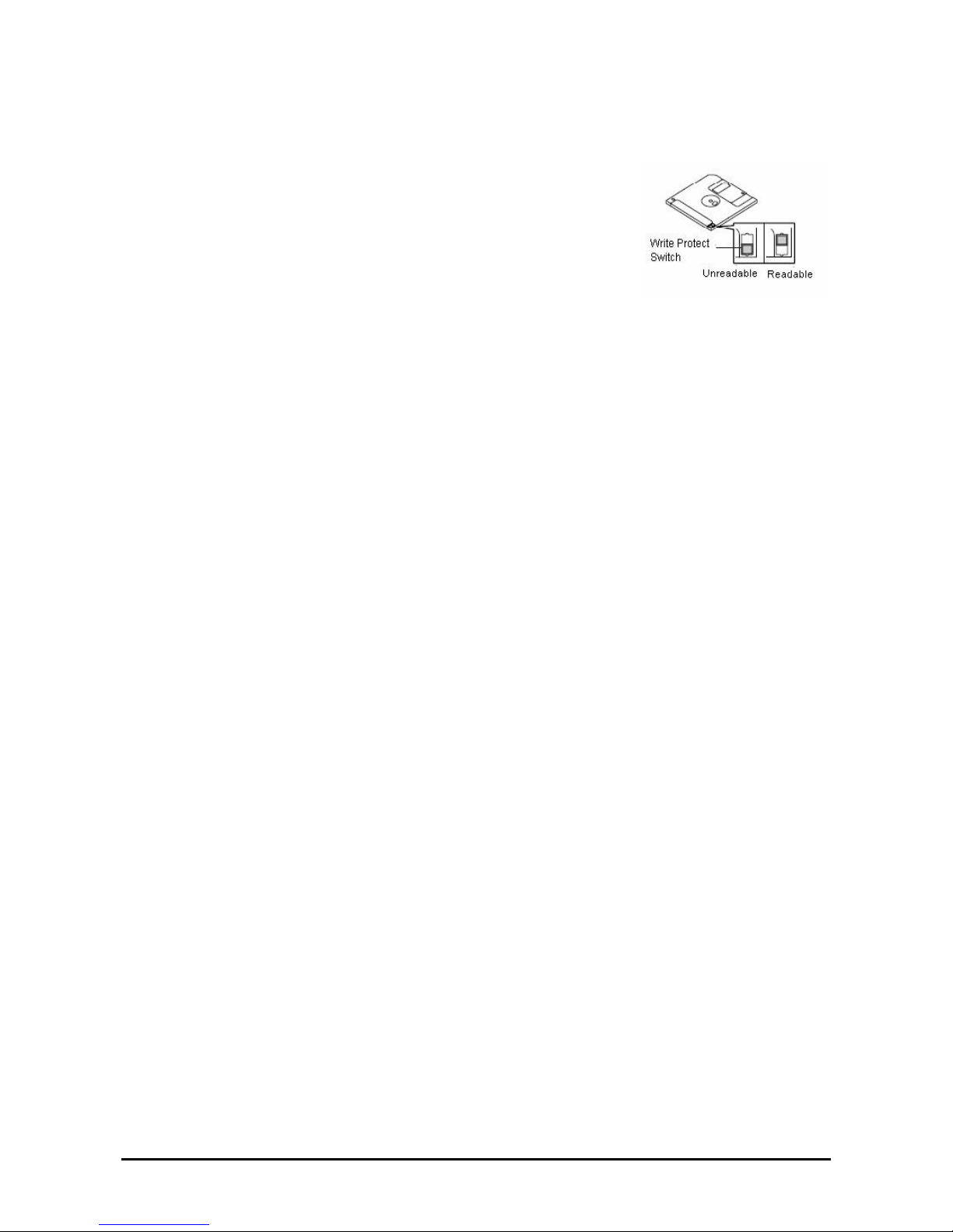
2-24
Store floppy disks in a protective case where they are kept away from magnetic waves or dust.
To prevent data from being erased accidentally, the floppy disk has a
write-protect notch. When the disk is write-protected, you can read data, but
you cannot write the data or format the disk. It is recommendable to
write-protect floppy disks that contain important data except when you write
data to the floppy disk. To write-protect a 3.5-inch floppy disk, slide the
write-protect notch located on its back.
The floppy disk is a very delicate storage medium. Dust or changes in
temperature could cause data to be lost. Data loss could also be caused by
faulty operation and computer trouble. To avoid such possible data loss, it is
recommendable to back up important data regularly. (Be sure to make back-up copies of the floppy disks that
are included with Fault Tolerant Server series.)
Page 49
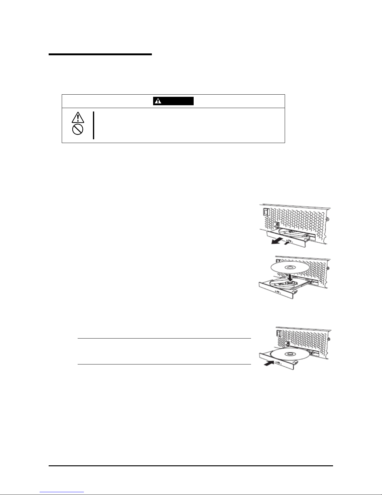
2-25
DVD-ROM drive
Fault Tolerant Server series has a DVD-ROM drive on the front panel. It is a device used to read data from an optical
disk (compact disc read-only memory). Compared to a floppy disk, an optical disk allows for larger volume and fast
data readout.
CAUTION
Observe the following instructions to use the server safely. There are risks of a
burn, injury, or damage to physical assets. For details, see “PRECAUTIONS
FOR SAFETY” in Chapter 1.
Do not leave the DVD-ROM drive tray ejected.
Insert/Remove DVD-ROM
Follow the steps below to set an optical disk.
1. Before you insert an optical disk, make sure that the server is powered on. When the server is powered on, the
LED illuminates in green.
2. Press the tray-eject button located in the front of the DVD-ROM drive. The
tray is then ejected.
3. Hold the optical disk with its signaling side facing the tray.
4. As shown in the figure on the right, place the optical disk on the tray and
press lightly on the center to lock.
5. Push the front side of the tray gently to the drive-closed position.
IMPORTANT:
If you hear noise while running the DVD-ROM drive, reset the optical
disk.
Page 50
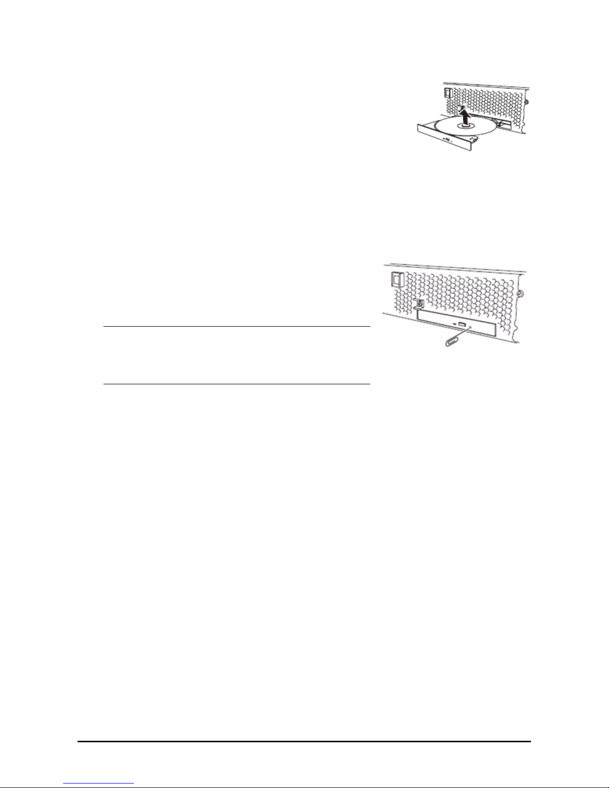
2-26
To remove the optical disk, press the tray-eject button as you did in setting the optical
disk.
When the access LED illuminates in orange, it indicates the optical disk is being
accessed. Make sure the access LED is not illuminating in orange before you press the
tray-eject button.
Press the locking part in the center of the tray and pick the optical disk gently. When
you have removed the optical disk, push the tray to the drive-closed position.
When you cannot eject a CD-ROM
When you cannot eject the optical disk from the server even by pressing the eject button, follow the steps below to eject
it:
1. Press the POWER switch to power off this server (i.e. the POWER LED is off).
2. Use a metal pin of about 1.2 mm in diameter and 100 mm long
(alternatively, you can use a fairly large paper clip after straightening).
Insert it gently into the manual release hole located at the low front side
of the server until the tray is ejected.
IMPORTANT:
Do not use a toothpick, plastic pin, or other breakable objects.
If you cannot eject the CD-ROM by following the steps above,
contact your sales agent.
3. Hold the tray and pull it out.
4. Take out the optical disk .
5. Push the tray back.
Page 51

2-27
Handling optical disks
Observe the following when you use an optical disk on Fault Tolerant Server series:
As for a disk such as a noncompliant “copy-protected CD,” we shall not guarantee that you can use a CD
player to play it with this server.
Be careful not to drop the optical disk.
Do not bend or place anything on the optical disk.
Do not attach labels on the optical disk.
Do not touch the signal side (blank side).
Place the optical disk gently on the tray with the printed side up.
Do not scratch, or use a pencil or ballpoint pen to write on the optical disk.
Keep away from cigarette smoke.
Do not leave the optical disk in a place that is subject to direct sunlight or high temperatures (e.g., due to a
heater).
If the optical disk gets dirty with dust or fingerprints, wipe it gently from its center to edge with a dry soft
cloth.
When you clean the optical disk, use the cleaner expressly meant for it. Do not use a record cleaner (spray),
benzine, or thinner.
Store the optical disk in a protective case when not in use.
Page 52

Chapter 3
Windows Setup and Operation
This chapter describes setup procedures to make Fault Tolerant Server series ready for use. CPU/IO module has a
processor function part and IO function part. In utilities in this chapter, the processor function part is referred to as CPU
module and IO function part PCI module.
3-1
Page 53
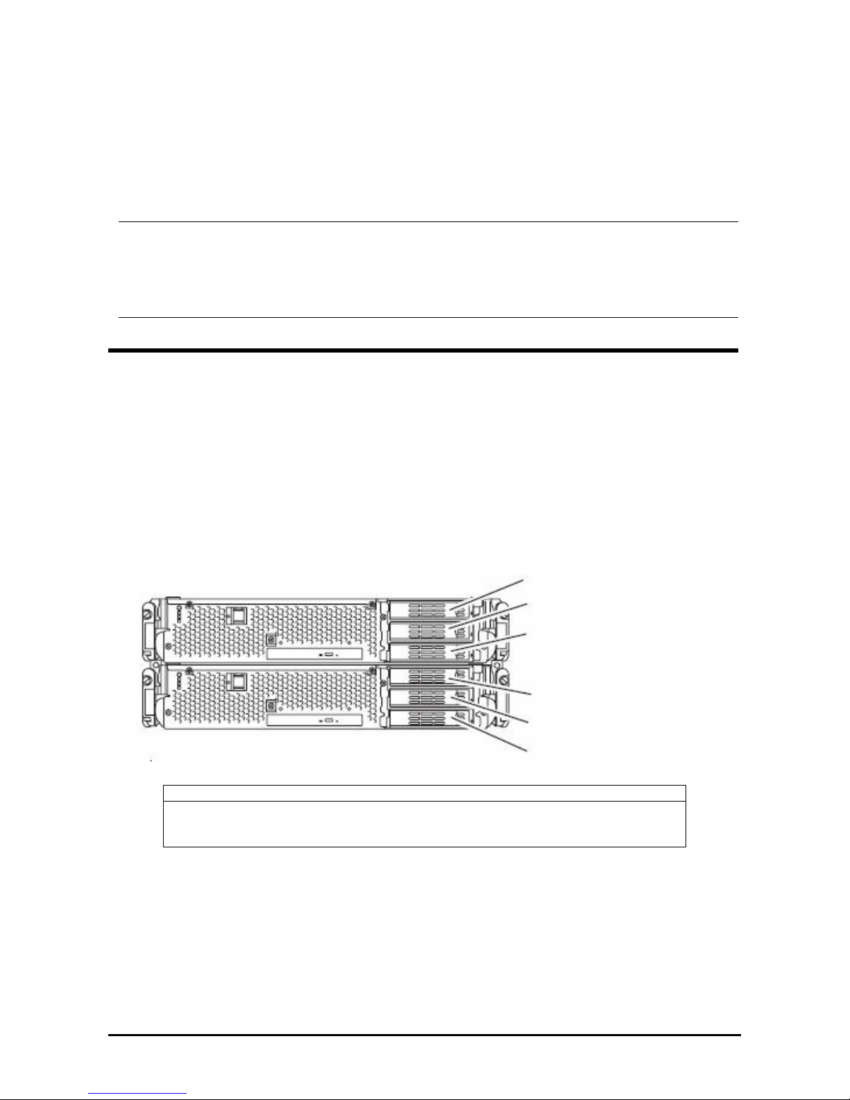
DISK OPERATIONS
This section explains the disk operation by the RDR (Rapid Disk Resync) function.
Fault Tolerant Server series duplicates disks to secure data by using “Rapid Disk Resync (RDR) function”. This section
describes operations such as configuration of dual settings to disks and replacement of disks.
IMPORTANT:
On the disks containing the OS, it is recommended to create only the system partition. To create a partition other than
a system partition on the disk with the OS, note the following:
If you reinstall the OS, the entire disk will be cleared. If there is any data partition other than the system partition, the
data must be backed up before reinstalling the OS.
Disk Operations Using the RDR (Rapid Disk Resync) Function
RDR (Rapid Disk Resync)
RDR function of ft control software secures reliability by making disks dup lexed per d isk. Dup lexing disk s by th e RDR
function enables the disks to be resynchronized in a short period of time when their mirror has been broken due to
causes such as PCI module replacement.
Setting RDR to disks duplicates the disks of paired slots as shown in the figure below and Windows (ex. Disk
Management and Device Manager) recognizes paired disks as a single virtual disk.
[Corresponding slots]
Slot 3
Slot 2
Slot 1
Slot 3
Slot 2
Slot 1
Slots corres
p
onding the mirroring process
Corresponding slots
PCI module 0 Slot 1 Ù PCI module 1 Slot 1
PCI module 0 Slot 2 Ù PCI module 1 Slot 2
PCI module 0 Slot 3 Ù PCI module 1 Slot 3
Note: In the above table, the PCI module names correspond to the following modules:
PCI module (for CPU/IO module 0): PCI module 0
PCI module (for CPU/IO module 1): PCI module 1
[Cautions for using the RDR function]
1. RDR can be set only to the disks inserted into the built-in slots of Fault Tolerant Server series.
2. Be sure to specify RDR to all disks inserted to the built-in slots and make dup lex settings.
3. RDR can be set only to basic disks.
If a span volume or stripe volume is needed, make settings of RDR to a basic disk and then change the disk to a
dynamic disk from [Disk Management].
3-2
Page 54
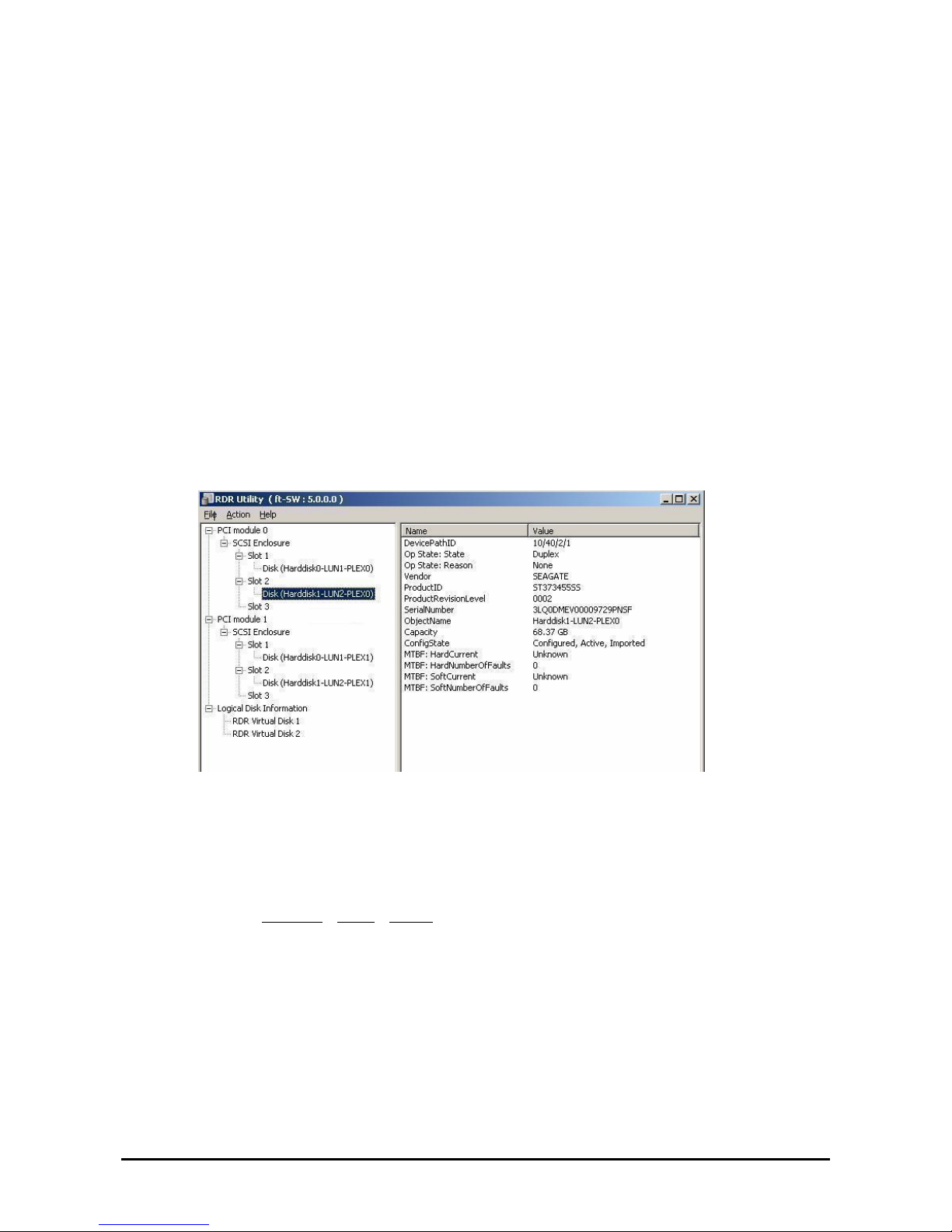
4. The disks to set RDR must have the same capacity and must be new or physically formatted.
(For physical format, refer to “SAS BIOS” in Chapter 4 and perform Format Disk using Disk Utilities.)
5. If the system is shut down (or restarted) while the mirror is broken, or a long time (30 hours or longer) has passed
after the mirror is broken, the mirror resynchronization target will be the entire disk.
For example, if the mirroring has been broken due to a PCI module failure, when you shut down the system and
replace the PCI module in such a state, the entire area of the disk needs to be resynchronized.
6. You must insert a new disk or replace a disk while the server is powered on.
Configuring and Removing Duplexed Setting of Disks by the RDR Function
This section describes how to make disks duplex and how to remove the settings by using the RDR function. To use the
RDR function, use [RDR Utility].
About RDR Utility
z Starting RDR Utility
From [Start], select [All Programs] then [RDR] and click [RDR Utility] to start [RDR Utility].
z Screen
[Left pane]
The tree shows disks inserted to the built-in slots and virtual disks (RDR Virtual Disks) created by RDR.
Right-click a disk on the tree to display the menu for setting RDR. By looking at the tree, you can know which
disk corresponds to which disk of the Windows’ [Disk Management] and whether RDR is set to the disk.
For example, in the case of the disk highlighted in the figure above:
Disk (
Harddisk1-LUN2-PLEX0)
(1) (2) (3)
(1) Corresponds to the number of Windows’ [Disk Management]. In this example, this disk is th e Disk1 on
[Disk Management].
(2) Corresponds to the number of a virtual disk created by RDR setting. In this example, this disk is a disk
which makes up the RDR Virtual Disk 2 (only appears for disks with RDR setting).
(3) This section appears only for disks with RDR setting.
[Right pane]
The properties of the disk selected in the left pane is shown.
In the figure above, the properties of the disk inserted to the Slot 2 of the PCI module 0.
3-3
Page 55
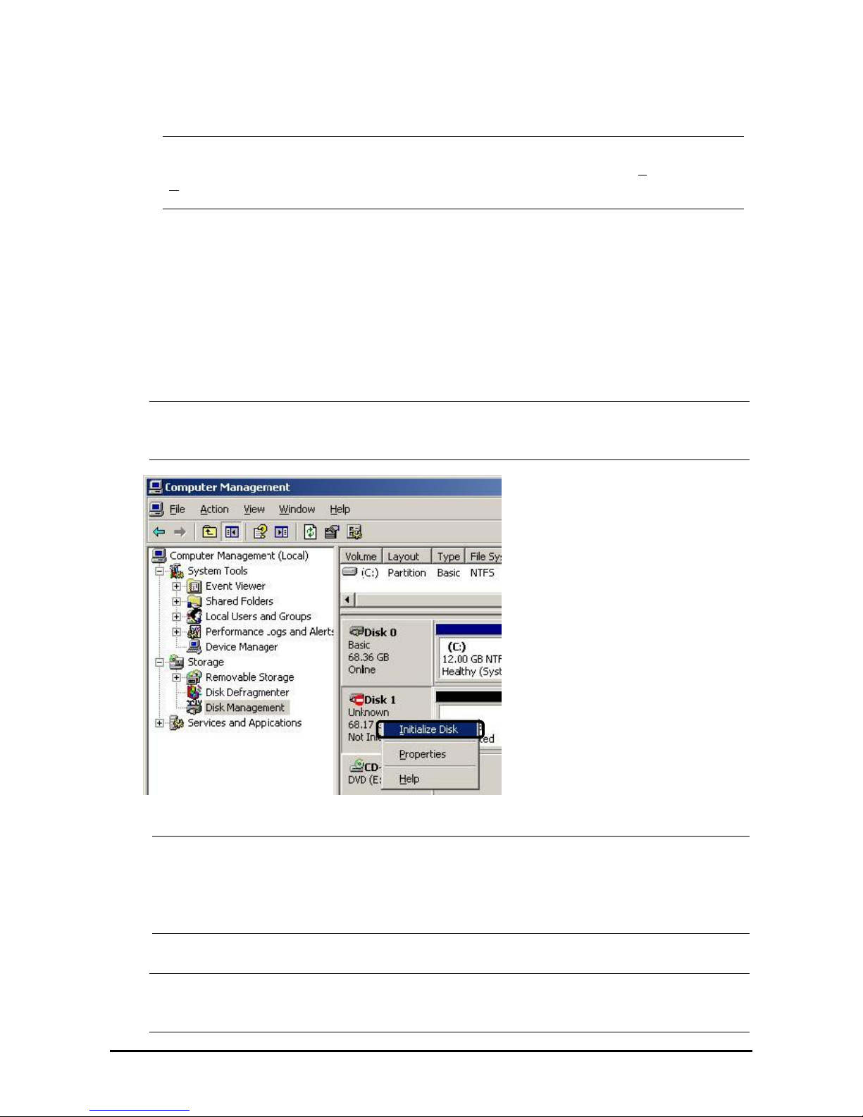
IMPORTANT:
The [RDR Utility] display is not updated automatically. Therefore, update it by clicking [Refresh] from
[
Action] on the menu or pressing F5 after performing operations to disk such as inserting/removing a disk,
specifying/removing the RDR setting.
Making disks duplex by RDR
The following describes the procedure to set duplex configurat i on to disk s by RDR.
In this example, the disks of the Slot 2 of the PCI modules 0 and 1 are duplexed.
1. Insert a new disk to a built-in slot.
(In this example, a disk is inserted to the Slot 2 of the PCI module 0.)
2. From [Start], select [Control Panel] then [Administrative Tools] and start [Computer Management]. On the tree in
the left pane, click [Disk Management].
If the inserted disk is indicated as [Not Initialized] in the right pane, right-click the disk and initialize it.
IMPORTANT:
When a disk is inserted or initialized, a popup window asking for rebooting the system may be displayed, but
there is no need to reboot it. Select [No] and close the popup window.
3.
Start RDR Utility.
IMPORTANT:
If the inserted disk does not appear on the tree, from the menu of RDR Utility, select [Action] and click
[Refresh] or press F5 to update the display after awhile.
The display of RDR Utility is not updated automatically. Therefo re, update it every time after you perform
disk operations described below.
4. On the left tree of RDR Utility, right-click a disk to set RDR and click [Create RDR Virtual Disk].
IMPORTANT:
Depending on the disk condition, RDR setting may take some time and RDR Utility may pause for a few
minutes. There is no error, so wait until the process is completed.
3-4
Page 56
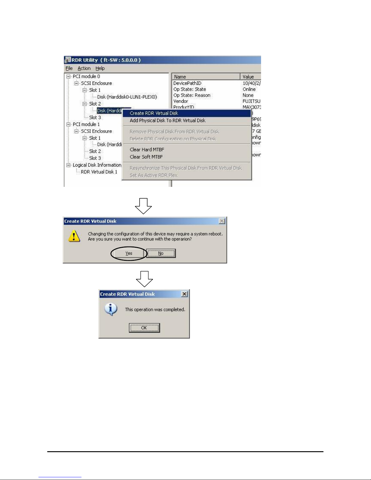
3-5
Page 57
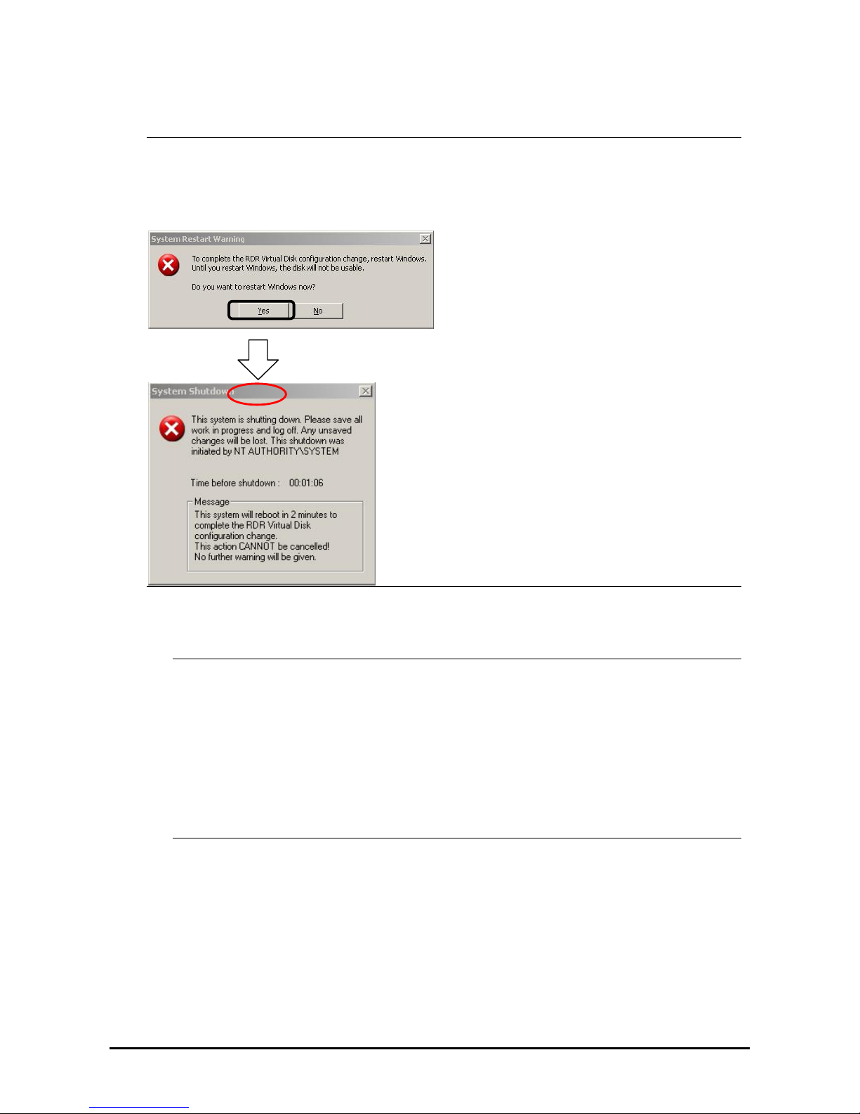
IMPORTANT:
If RDR is specified to a disk which contains the system partition or partition which cannot be unmounted, the
following pop-up message appears. If you click [Yes], the system is restarted in two minutes automatically. Go
on to 5. when the system is restarted.
5.
Insert a disk to set duplex configuration into the corresponding slot.
(In this example, a disk is inserted into the Slot 2 of the PCI module 1.)
IMPORTANT:
When a disk is inserted, a popup window asking for rebooting the system may be displayed, but there
is no need to reboot it. Select [No] and close the popup window.
For a disk to be inserted, use a new or physically formatted disk which has the same capacity as the
synchronization source. If such a disk is not used, disks are not duplicated successfully.
For physical format, see “SAS BIOS ~ Adaptec SAS/SATA Configuration Utility ~” in Chapter 4 “System
Configuration” and perform Format Disk with Disk Utilities. When performing Format Disk, on BIOS
Setup Utility, click [Server], [Monitoring Configuration] and disable [Option ROM Scan Monitoring]. For
how to set up, see “SYSTEM BIOS ~ SETUP ~” on Chapter 4 “System Configuration.”
3-6
Page 58
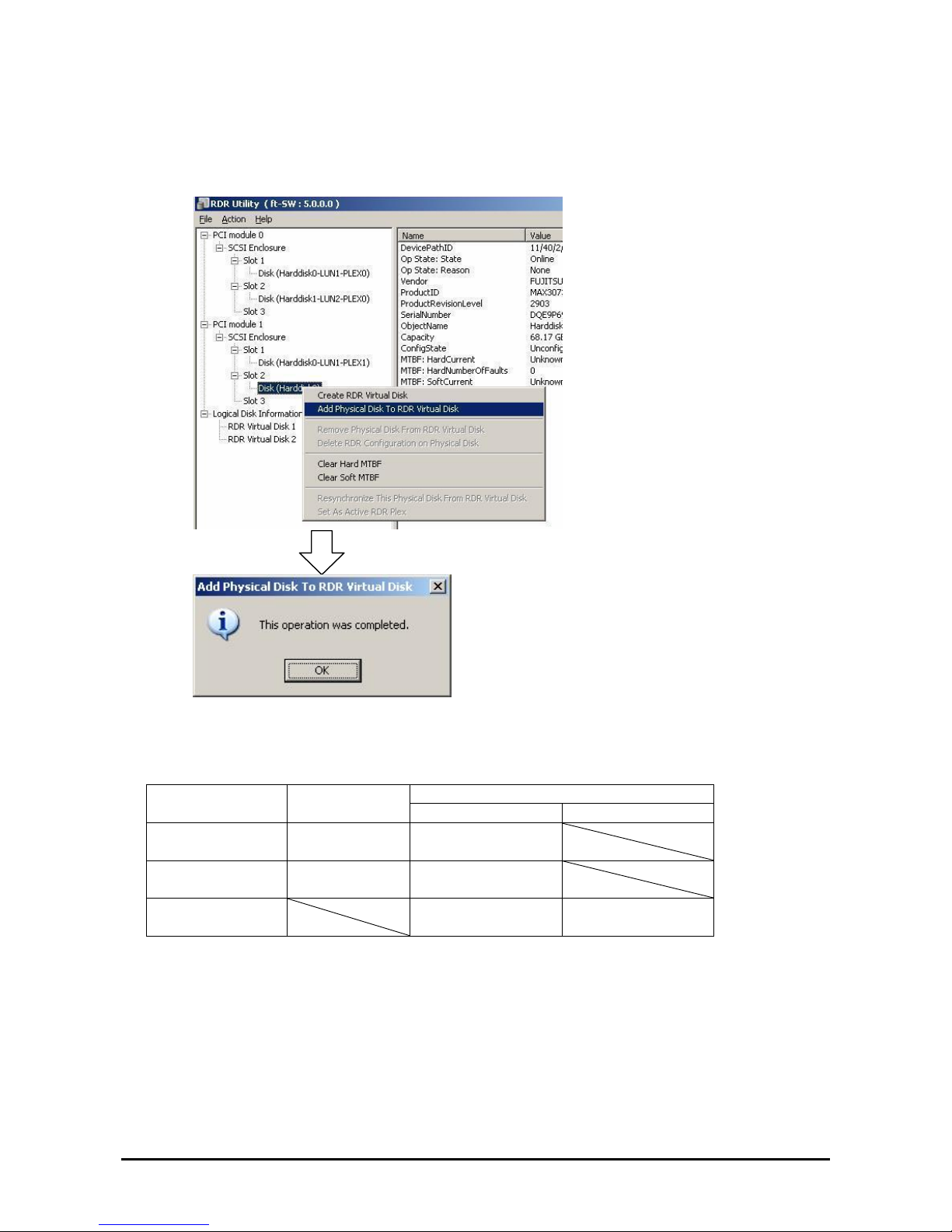
6.
On the left tree of RDR Utility, right-click a disk to set RDR and click [Add physical Disk To RDR Virtual
Disk].
7. Confirm that synchronizing disks are started and the DISK ACCESS LEDs and the display of RDR utility
change as shown below:
Synchronizing
RDR Utility
DISK ACCESS
LED
Op State: State Status
Source disk Amber
(Blinking)
Simplex
Destination disk Amber
(Blinking)
Syncing
RDR Virtual Disk
Simplex
Resync x percent
(x=0, 10, 20, ..., 90)
3-7
Page 59
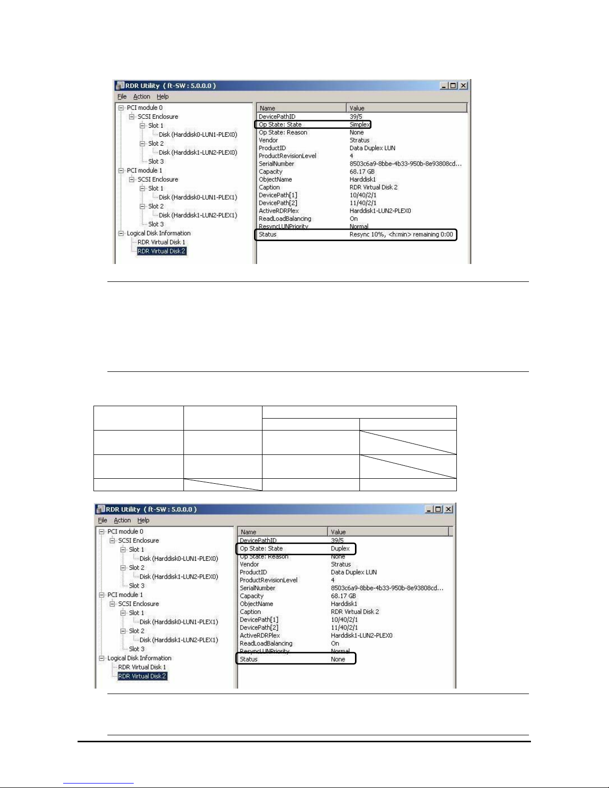
IMPORTANT:
The time required for synchronization varies depending on the partition size on the d isk.
For 18GB partition, it takes about 16 minutes.
If there is no partition, synchronization may complete in a short period of time and the disk may become
synchronized after RDR is set.
If the system is rebooted during synchronization, the process cannot be completed. Do not restart the system
until the synchronization is completed.
Synchronization completed
RDR Utility
DISK ACCESS
LED
Op State: State Status
Source disk Green
(Blinking)
Duplex
Destination disk Green
(Blinking)
Duplex
RDR Virtual Disk Duplex None
IMPORTANT:
When a new partition is created on the disk where RDR is set, the created partition area is synchronized
3-8
automatically.
Page 60

re RDR is set is converted to a dynamic disk, the area which has not been synchronized When the disk whe
(the area where no partition exists) will be synchronized.
dows properly, for example, by pressing the power When the system is shut down without shutting down Win
button, the entire area of the synchronized disks will be resynchronized after the system is restarted.
3-9
Page 61
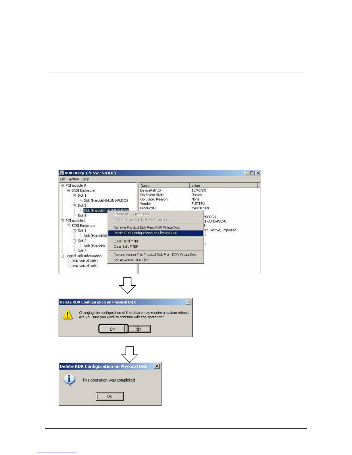
Removing duplex configuration of RDR disks
This section describes how to remove duplex configuration from the disk with RDR setting.
In the example below, the duplication setting of the disks in the Slot 2 of the PCI modules 0 and 1 is removed.
IMPORTANT:
After executing the command, RDR settings will be cancelled but other data will remain.
You cannot release the duplex setting of the following disks:
・ Disk containing page files
・ Dynamic disk
To release the dual disk setting including the boot partition/volume, return the disk status to the Simplex first
and then release the setting.
The display of RDR Utility is not updated automatically. Therefore, update it every time you check the status of
disks by clicking [Refresh] from [Action] on the menu or pressing F5.
1. Start the RDR Utility, right-click a disk you want to cancel RDR from the tree in the left pane, and select [Delete
RDR configuration on Physical Disk].
3-10
Page 62
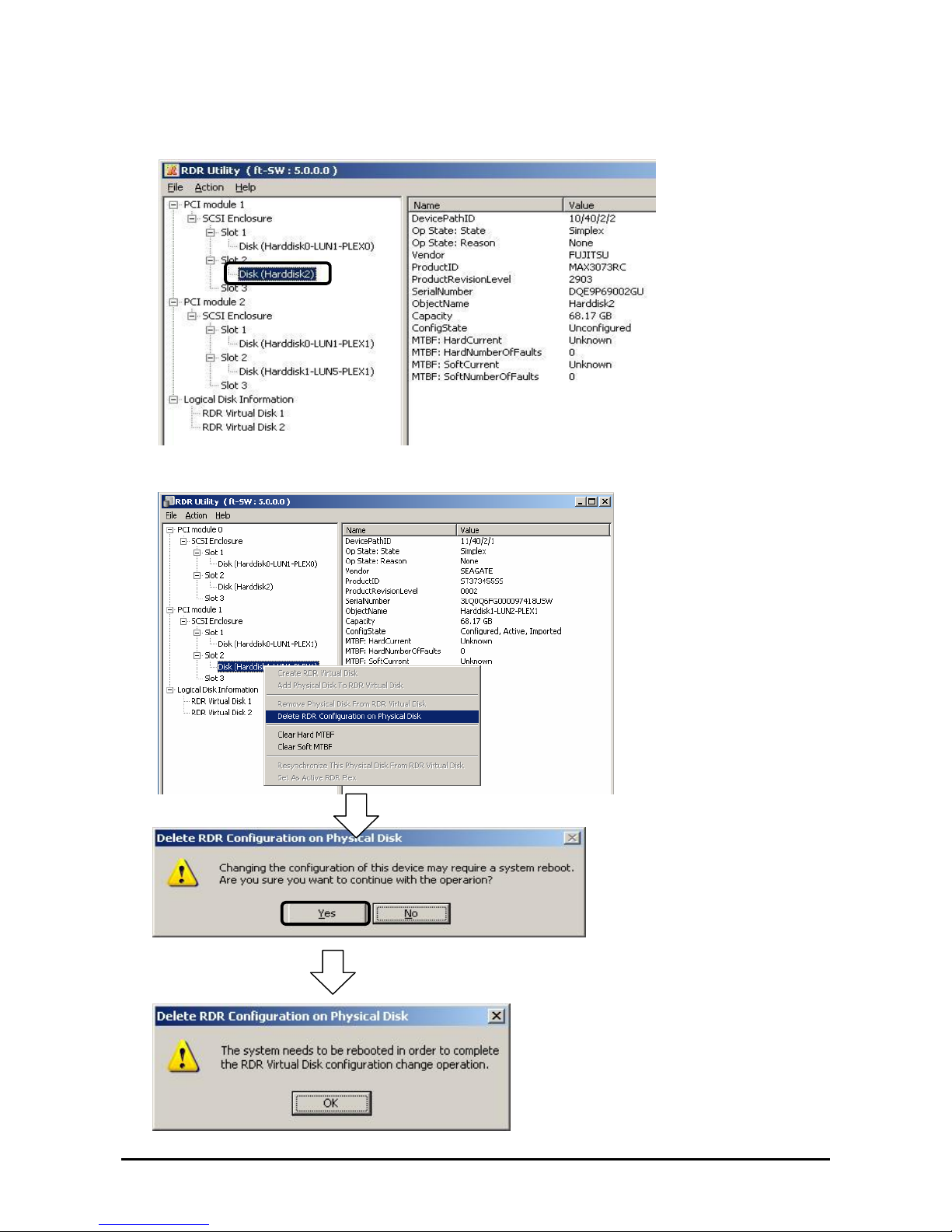
2. Confirm that RDR of the disk is cancelled.
3. Cancel the disk of the corresponding slot in the same manner.
3-11
Page 63
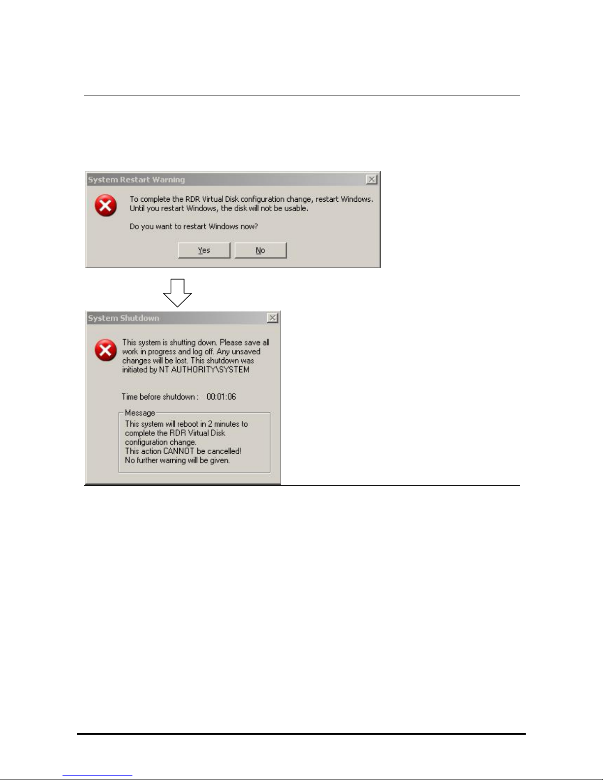
IMPORTANT:
A partition on the disk where the RDR setting is removed is not assigned a drive letter. To use the partition,
assign a drive letter using [Disk Management].
If the disk contains a partition which cannot be unmounted, the OS needs to be restarted when canceling RDR.
In that case, the following pop-up message appears. If you click [Yes], the OS is restarted after two minutes
automatically:
3-12
Page 64
Other functions of RDR Utility
<Commands for physical disks>
Remove Physical Disk From RDR Virtual Disk
All data including RDR settings on a physical disk can be deleted.
IMPORTANT:
After executing the command, the physical disk becomes an empty basic disk without RDR settings.
This command can only be executed to physical disks in Duplex/Syncing state.
1. Start RDR Utility and right-click a target disk on the tree in the left pane, and click [Remove Physical Disk from
RDR Virtual Disk].
2. In the [Remove Physical Disk From RDR Virtual Disk] dialog box, click [Yes].
3. In the [Remove Physical Disk From RDR Virtual Disk] dialog box, click [OK].
Clear Hard MTBF
When a hardware failure occurs to a disk, the mean time between failures (MTBF) is counted and the value is saved. In
RDR Utility, the value is displayed at [MTBF: HardCurrent] and [MTBF:HardNumberOfFaults].
These MTBF values can be cleared by the [Clear Hard MTBF] command.
1. Start RDR Utility and right-click a target disk on the tree in the left pane, and click [Clear Hard MTBF].
2. In the [Clear Hard MTBF] dialog box, click [OK].
Clear Soft MTBF
When a software failure occurs to a disk, the mean time between failures (MTBF) is counted and the value is saved. In
RDR Utility, the value is displayed at [MTBF: SoftCurrent] and [MTBF:SoftNumberOfFau lts].
These MTBF values can be cleared by the [Clear Soft MTBF] command.
1. Start RDR Utility and right-click a target disk on the tree in the left pane, and click [Clear Soft MTBF].
2.
In the [Clear Soft MTBF] dialog box, click [OK].
Resynchronize This Physical Disk From RDR Virtual Disk
Disks whose synchronization by RDR is cancelled for reasons including a failure can be resynchronized.
1. Start RDR Utility and right-click a target disk in the left pane and click [Resynchronize This Physical Disk From
RDR Virtual Disk].
2. In the [Resynchronize This Physical Disk From RDR Virtual Disk] dialog box, click [OK].
3. Confirm that the resynchronization starts and the status of disks changes as shown below:
Resynchronizing
RDR Utility
DISK ACCESS
LED
Op State: State Status
Source disk Amber
(Blinking)
Simplex
Destination disk Amber
(Blinking)
Syncing
RDR Virtual Disk
Simplex
Resync x percent
(x=0, 10, 20, ..., 90)
3-13
Page 65
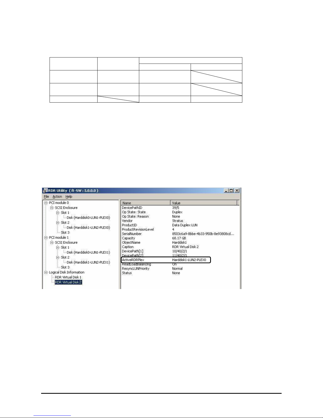
Synchronization completed
RDR Utility
DISK ACCESS
LED
Op State: State Status
Source disk Green
(Blinking)
Duplex
Destination disk Green
(Blinking)
Duplex
RDR Virtual Disk Duplex None
Set As Active RDR Plex
A physical disk can be set as “Active RDR Plex” by a command.
Active RDR Plex is the disk on which data reading process is performed when Load Balancing of RDR Virtual Disk is
off.
1. Start RDR Utility and right-click a target disk in the left pane and click [Set As Active RDR Disk].
2. In the [Set As Active RDR Plex] dialog box, click [OK].
Active RDR Plex can be viewed from [Active RDR Plex] of RDR Virtual Disk. (In the image below, the disk in the slot
2 of PCI module 0 is set to Active RDR Plex among physical disks constructing RDR Virtual Disk 2.)
<Commands for RDR Virtual Disk>
3-14
Page 66
Verify RDR Virtual Disk
Whether the synchronization by RDR is performed normally can be checked.
1. Start RDR Utility and right-click [RDR Virtual Disk x] in the left pane and click [Verify RDR Virtual Disk].
2. In the [Verify RDR Virtual Disk] dialog box, click [OK].
The progress of verification can be viewed using RDR Utility.
Verifying Verification completed
[Status] of RDR Virtual Disk x
Verify x percent
(x=0, 10, 20, …, 90)
None
TIPS:
The verification process is automatically performed every 1 week.
The time required for verification depends on the disk size and load.
Stop Verifying RDR Virtual Disk
Verification of RDR virtual disk in progress can be stopped.
1. Start RDR Utility and right-click [RDR Virtual Disk x] in the left pane and click [Stop Verify RDR Virtual Disk].
2. In the [Stop Verify RDR Virtual Disk] dialog box, click [OK].
Set Resync Priority
Priority of synchronization by RDR can be specified. By changing the priority, I/O load during synchronization can be
reduced.
1. Start RDR Utility, right-click [RDR Virtual Disk x] in the left pane and click [Set Resync Priority].
2. When a dialog box appears, select Low, Normal or High (a default is Normal) and click [OK].
3. In the [Set Resync Priority] dialog box, click [OK].
Set RDR LUN Load Balancing
On or off of load balancing can be specified.
When the load balancing is on (default), the read process is performed alternately from two physical disks forming the
RDR Virtual Disk to improve performance. When it is off, the read process is performed from the physical disk
specified as Active RDR Plex.
1. Start RDR Utility, right-click [RDR Virtual Disk x] in the left pane to chang e the priority and click [Set RDR
LUN Load Balancing].
2. When a dialog box appears, select On or Off (a default is On) and click [OK].
3. In the [Set RDR LUN Load Balancing] dialog box, click [OK].
3-15
Page 67
Replacing Failed Hard Disk Drives
The following describes how to locate and replace the failed hard disk. The failed hard disk should be replaced
with the server powered on.
How to Locate Failed Disks
1. From [Start], select [All Programs], [RDR] and click [RDR Utility] to start RDR Utility.
2. From the tree on the left pane of [RDR Utility], select each disk and check the values of [MTBF: Current]
and [MTBF:NumberOfFaults] in the right pane.
TIPS:
For RDR Utility, see “About RDR Utility” on pag e 3-3.
[Description of each MTBF value]
Property name Description Normal value*
MTBF: HardCurrent Mean time between hardware failures. Unknown
MTBF: SoftCurrent Mean time between software failures. Unknown
* The normal value denotes the value of when no error has occurred.
If either of the values is different from the normal value, the disk has an error.
Procedures to Replace Failed Disks
This section describes a procedure for replacing a disk when a failure occurs to a d isk that is duplicated by the RDR
function.
IMPORTANT:
The display of RDR Utility is not updated automatically. Therefore, update it every time you check the status of disks
by clicking [Refresh] from [Action] on the menu or pressing F5. Do not update RDR Utility frequently immediately
after inserting a disk.
Here, an example that a failure of the disk in slot 2 of the PCI module 0 is determined as described in “
How to Locate
Failed Disks
” is explained.
1. From [Start], click [All Programs], point to [RDR], and select [RDR Utility] to start RDR Utility.
2. Remove the disk in the slot 2 of the PCI module 0.
3. Insert a new disk to the slot 2 of the PCI module 0.
RDR is automatically set to the inserted disk and synchronization starts.
3-16
Page 68
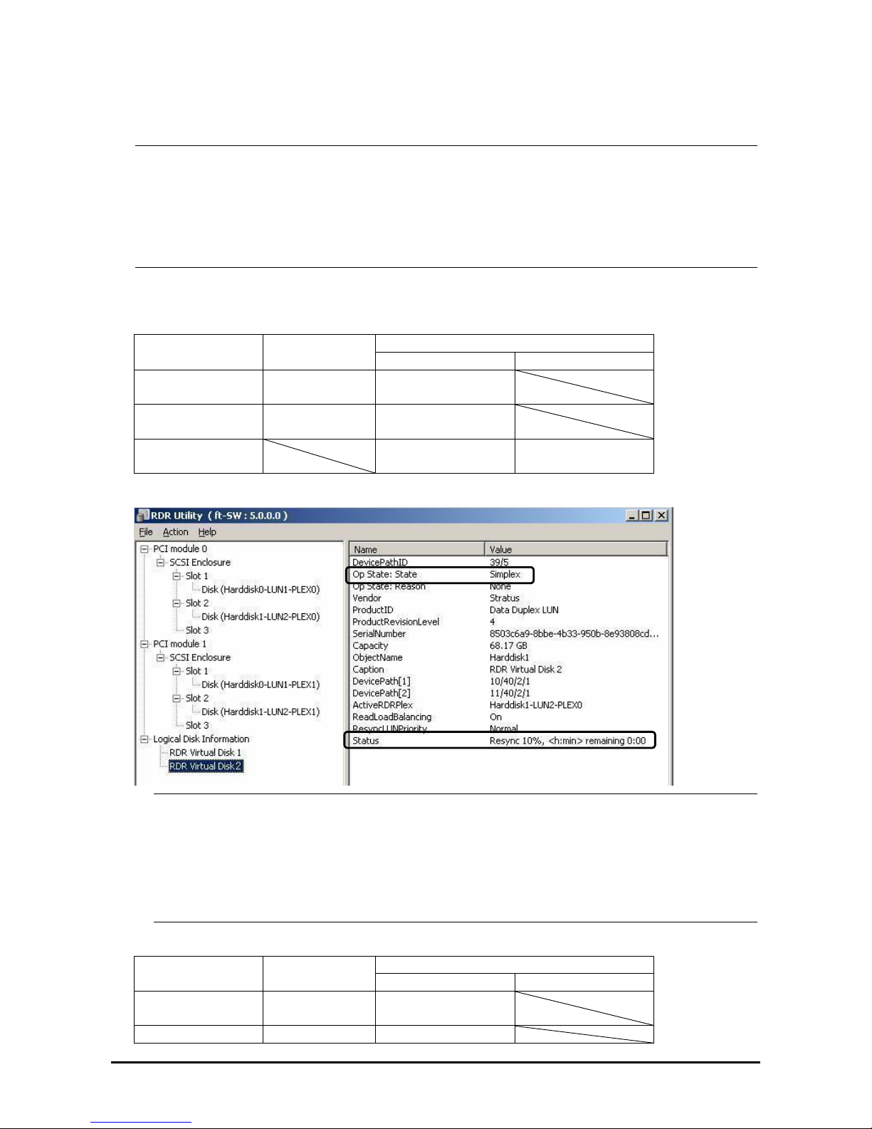
IMPORTANT:
For a disk to be inserted, use a new or physically formatted disk which has the same capacity as the disk of
the corresponding slot (in this example, the disk in slot 2 of the PCI module 0)
When a disk is inserted, a popup window asking for rebooting the system may be displayed, but there is no
need to reboot it. Select [No] and close the popup window.
Insert the replacement disk after waiting for 15 seconds or more after removing a disk.
4.
Confirm that the DISK ACCESS LEDs and the display of RDR Utility change as shown below:
Synchronizing
RDR Utility
DISK ACCESS
LED
Op State: State Status
Source disk Amber
(Blinking)
Simplex
Destination disk Amber
(Blinking)
Syncing
RDR Virtual Disk
Simplex
Resync x percent
(x=0, 10, 20, ..., 90)
IMPORTANT:
The time required for synchronization varies depending on the partition size on the d isk.
For 18GB partition, it takes about 16 minutes.
If there is no partition, synchronization may complete in a short period of time and the disk may become
synchronized after RDR is set.
If the system is rebooted during synchronization, the process cannot be completed. Do not restart the system
until the synchronization is completed.
Synchronization completed
RDR Utility
DISK ACCESS
LED
Op State: State Status
Source disk Green
(Blinking)
Duplex
Destination disk Green Duplex
3-17
Page 69
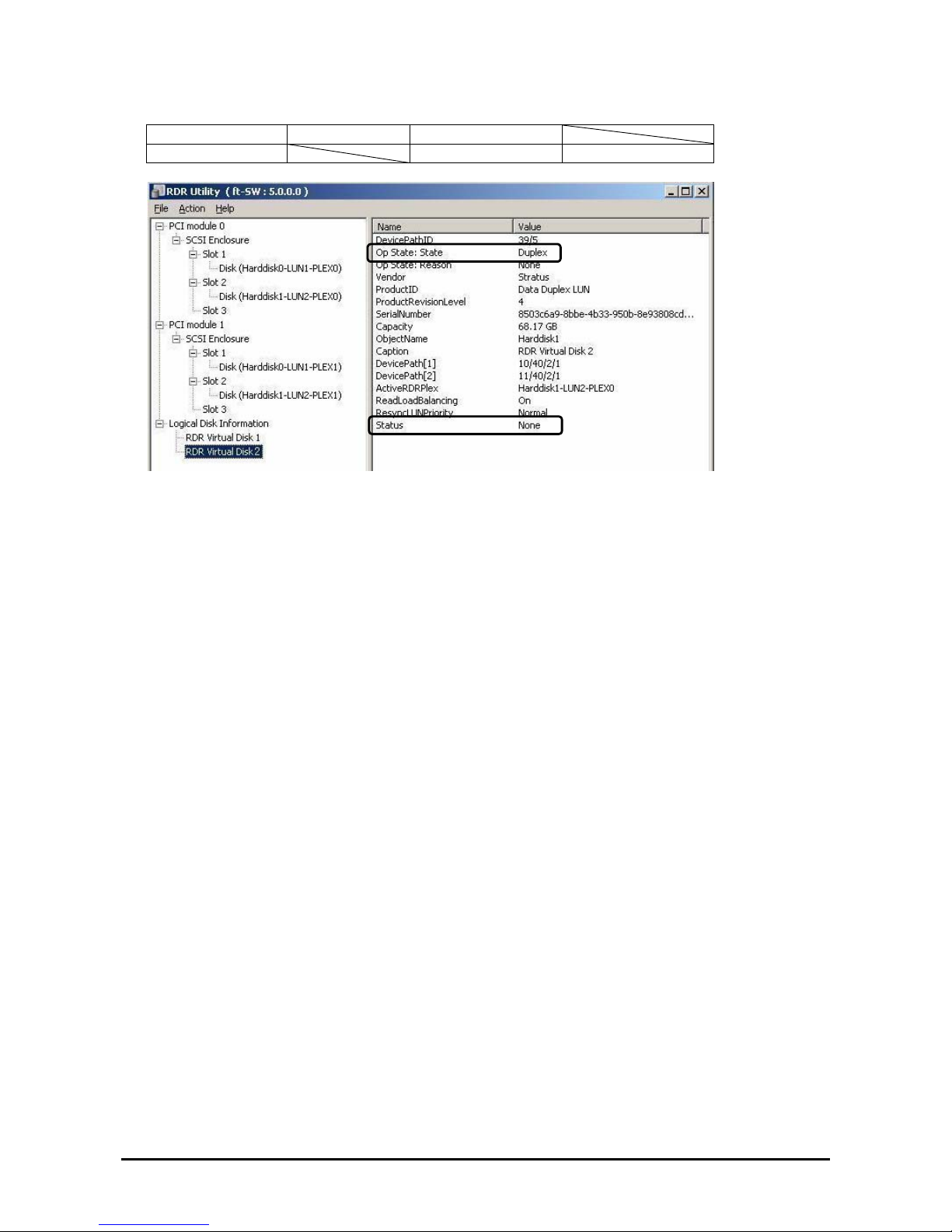
(Blinking)
RDR Virtual Disk Duplex None
3-18
Page 70

CHANGE DRIVE LETTER
To add , change or delete drive letters, follow the steps below. Before making any changes, thoroughly read the Fault
Tolerant Server series-specific precautions and general precautions for Windows.
1. Select [Start] - [Control Panel] - [Administrative Tools] and open [Computer Management].
2. In the console tree of [Computer Management], click [Disk Management].
3. Right-click a target partition, logical drive or volume and click [Change Drive Letter and Paths…].
4. Perform one of the following:
z To assign a drive letter, click [Add…], a drive letter to use, then [OK].
z To change a drive letter, click the drive letter to change, [Change…], a drive letter to use, then [OK].
z To delete a driv e letter, click the drive letter to delete then [Remove].
IMPORTANT:
<Fault Tolerant Server series-specific precautions>
When connecting an optional floppy disk drive, drive letters may change from A to B by switching CPU/IO
modules.
<General precautions for Windows>
Drive letter of system volume or boot volume cannot be changed.
Up to 26 dr ive letter s can be used on a co mputer . “A” and “B” are drive letters for floppy disk drives. G enerally,
hard disk drives are assigned “C” to “Z”, but for network drives, drive letters are assigned in a reverse order (“Z”
to “C”).
Because many of Windows programs refer to specific drive letters, cautions are required for assigning drive
letters. For example, the Path environment variable specifies a program name and a specific drive letter.
For perf orming the procedure above, you need to be a member of Backup Operators group or Administrators
group, or you need to have appropriate authorization.
3-19
Page 71
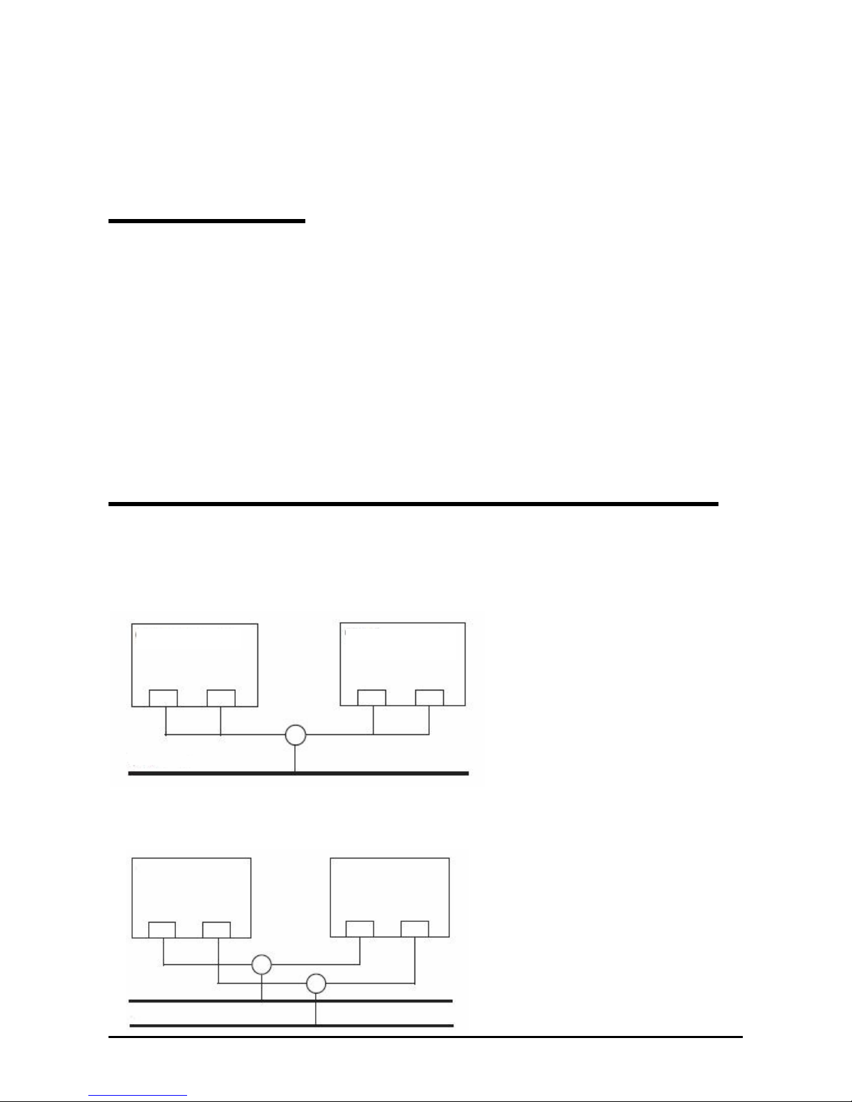
DUAL LAN CONFIGURATION
The Fault Tolerant Server series builds a dual LAN configuration by using “Stratus emb-EB 2-Port Gigabit Adapter,”
mounted as standard on the CPU/IO module and “Intel(R) PRO/1000 MT Server Adapter” and “Intel(R) PRO/1000 MF
Server Adapter” inserted in the extended PCI slots, .
Overview
The dual LAN configuration is of two types as described below:
Adapter Fault Tolerance (AFT)
Adapter Fault Tolerance (AFT) is a feature that places more than one LAN controller on the same LAN (same
segment), and automatically switches the process of the primary controller to the backup controller when any
trouble occurred on the primary.
Adaptive Load Balancing (ALB)
Adaptive Load Balancing (ALB) is a feature that connects more than one LAN controller to the same hub and
enhances the throughput by operating packet transmission from the server.
Receive Load Balancing (RLB) is enabled by default. When RLB is enabled, the receiving throughput is enhanced.
The other modes, “Static Link Aggregation” and “IEEE 802.3ad Link Aggregation,” do not contribute to enhancement
against a fault. When a fault occurs, the communication performed on the controller with the fault is not taken over by
the backup controller but lost.
Rules of Dual Configuration on Fault Tolerant Server series
Be sure to make the setting of dual network configuration on the server.
When building dual configuration, be sure to use at least one adapter of CPU/IO module 0 and of 1 individually.
Example1) Configure the dual network which enhances the service life by using all adapters.
CPU/IO module 1
CPU/IO module 0
Network
Example 2) Configure the dual network which corresponds to multiple LAN connection.
Network 2
Network 1
CPU/IO module 1 CPU/IO module 0
3-20
Page 72
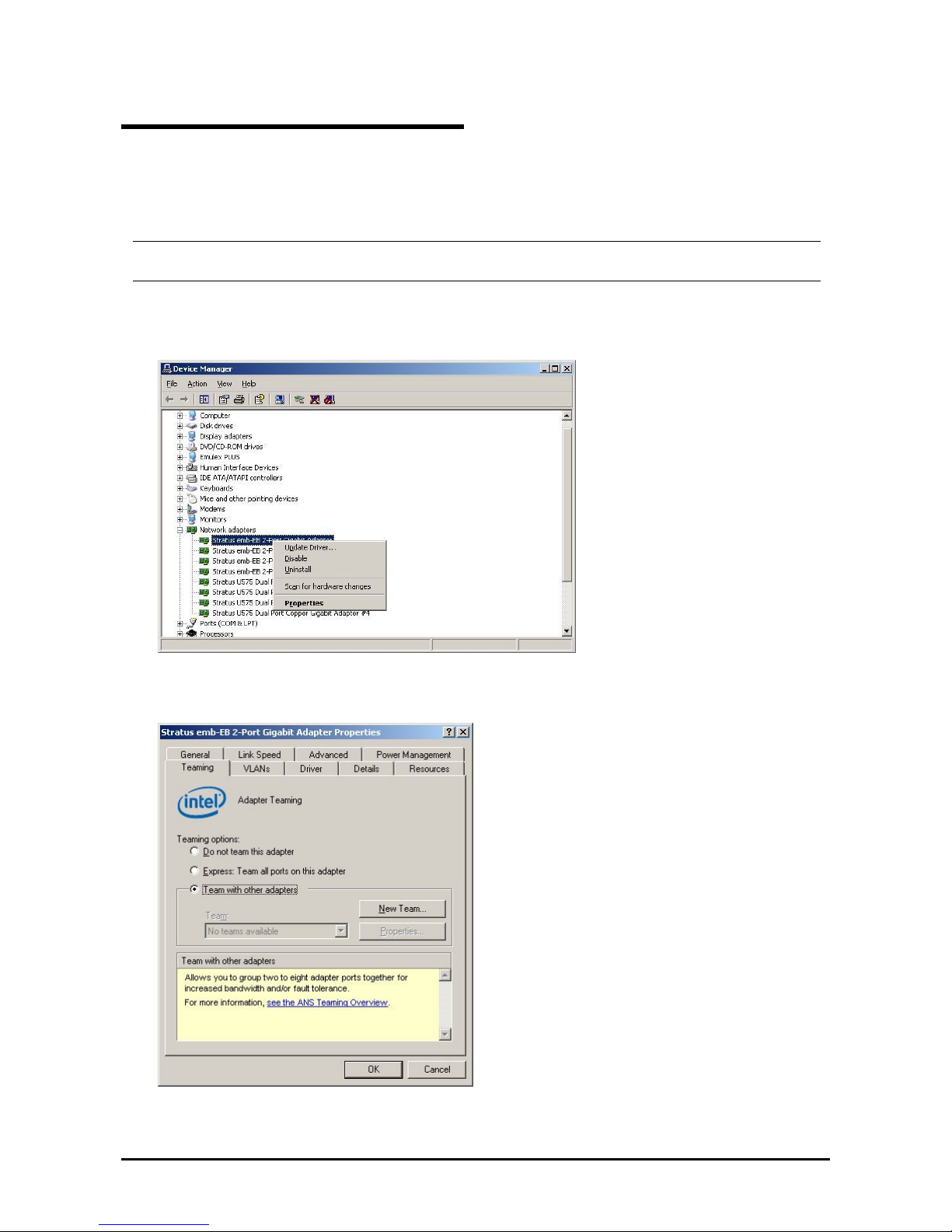
Configuring Dual LAN
This section describes how to configure dual LAN.
The following explains how to configure dual LAN regarding to the example shown in “
Rules of Dual Configuration
on Fault Tolerant Server series
.”
IMPORTANT:
Log on as "Administrator" or a member of the group "Administrators."
1. Start [Device Manager].
2. Select a target Network Adapter. Right-click on it and select [Properties] from the menu displayed to show the
properties dialog box.
3. Select the [Teaming] tab on the properties dialog box. Select the [Team with other adapters], and then click the
[New Team…] button.
4.
Enter the team name and click [Next].
3-21
Page 73
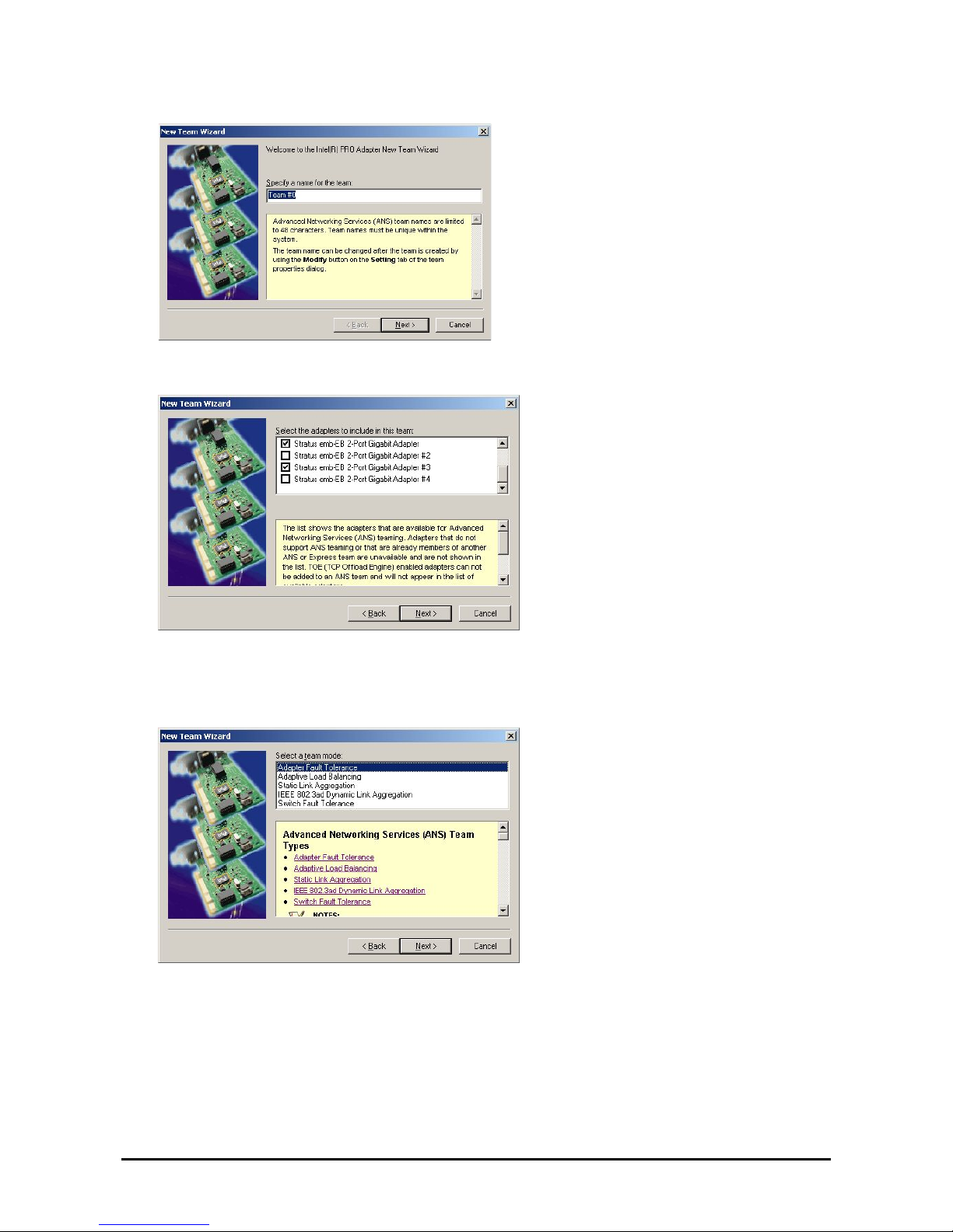
5. Select the adapters to include in the team and click [Next].
6.
Select [Adapter Fault Tolerance] or [Adaptive Load Balancing] as a team mode (Usually select [Adapter Fault
Tolerance]).
Click [Next].
3-22
Page 74
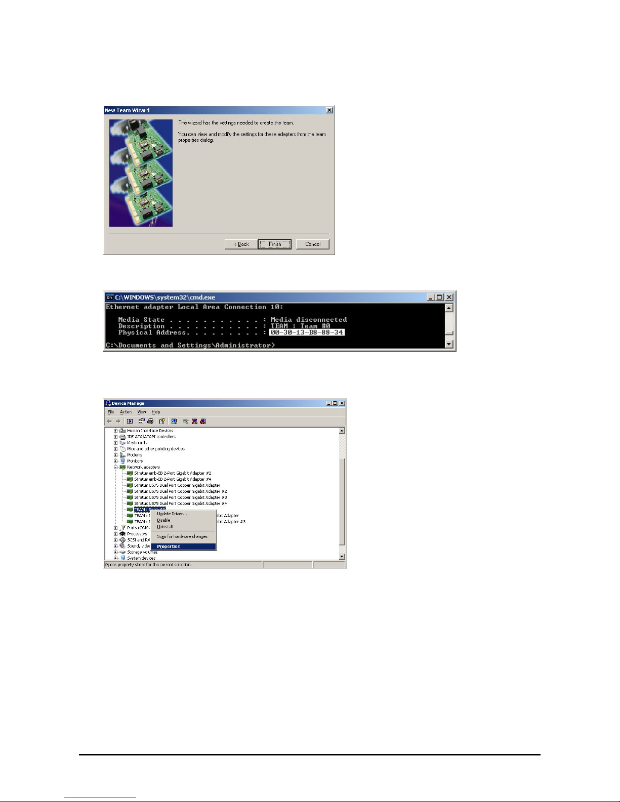
7. Click [Finish].
8. Start Command prompt to check the physical MAC address set on ipconfig/all.
9. Select the Team Adapter you have set. Right-click on it and select [Properties] from the menu disp layed to show
the properties dialog box.
3-23
Page 75
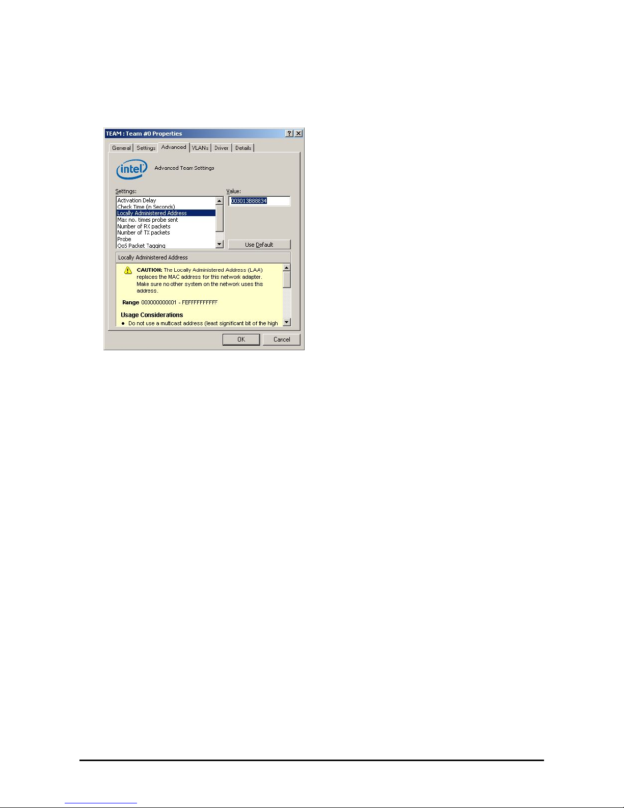
10. Select the [Advanced] tab on the properties dialog box. Select [Locally Administered Address] from the [Settings]
list box, and then enter the MAC address of a Team Adapter, which you have checked, in the [Value] text box.
Click [OK].
3-24
Page 76
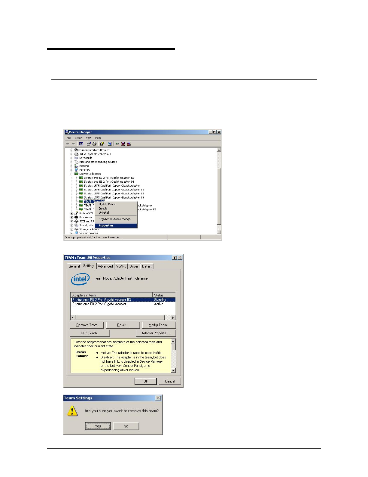
Removing Dual LAN
This section describes how to remove dual LAN.
IMPORTANT:
Log on as "Administrator" or a member of the group "Administrators.”
1. Start [Device Manager].
2. Select the Team Adapter of which you want to remove dual LAN. Right-click on it, and then select [Properties]
from the menu displayed to show the properties dialog box.
3.
Select the [Settings] tab in the properties dialog box and click the [Remove Team] button.
4.
The confirmation dialog box appears. Click [Yes] but t on.
3-25
Page 77
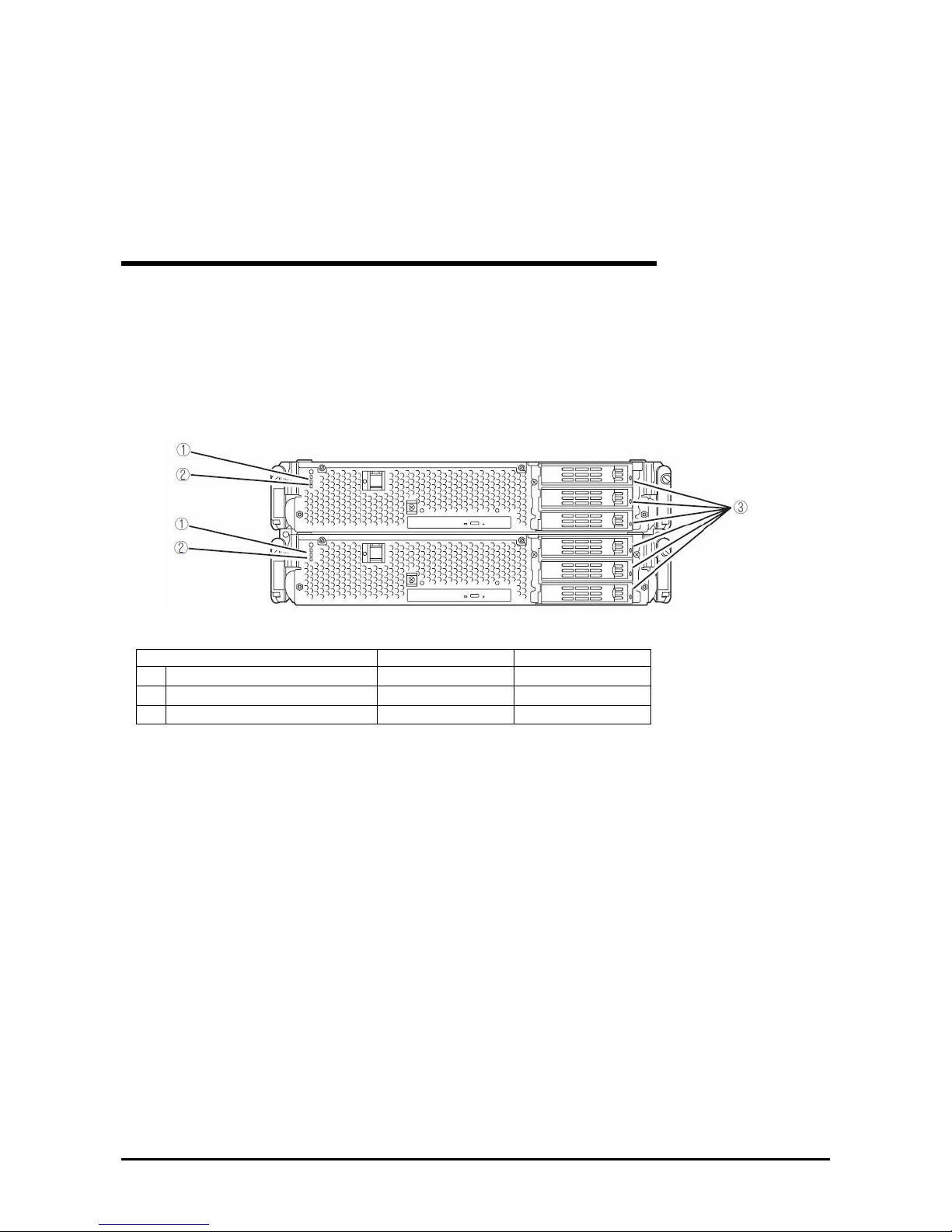
CHECK THE DUPLICATING OPERATION OF MODULES
This section describes how to check if the system runs properly after system installation or reinstallation. CPU/IO
module has a processor function part and IO function part. Each part is monitored and managed by the
module. In this section, the processor function part is referred to as CPU module and IO function part PCI
module.
Evaluate Startup and Stop of PCI Modules
This section describes how to confirm the continuous system operation by failover after stopping the primary PCI
module.
1.
Check which is the primary PCI module.
The PCI module with the POWER switch illuminated is the primary module.
2.
Check whether the PCI modules are duplicated.
To check if the PCI modules are duplicated, see the CPU/IO modules’ status LEDs.
[
Indications of the status LEDs when PCI modules are duplicated]
LED Primary Secondary
1
CPU/IO module status LED1 - -
2
CPU/IO module status LED2 Green Green
3
DISK ACCE SS LED Green blinking Green blinking
* The numbers in the table correspond to the numbers in the above figure.
The DISK ACCESS LED (3) lights when the hard disk drive is accessed.
3-26
Page 78
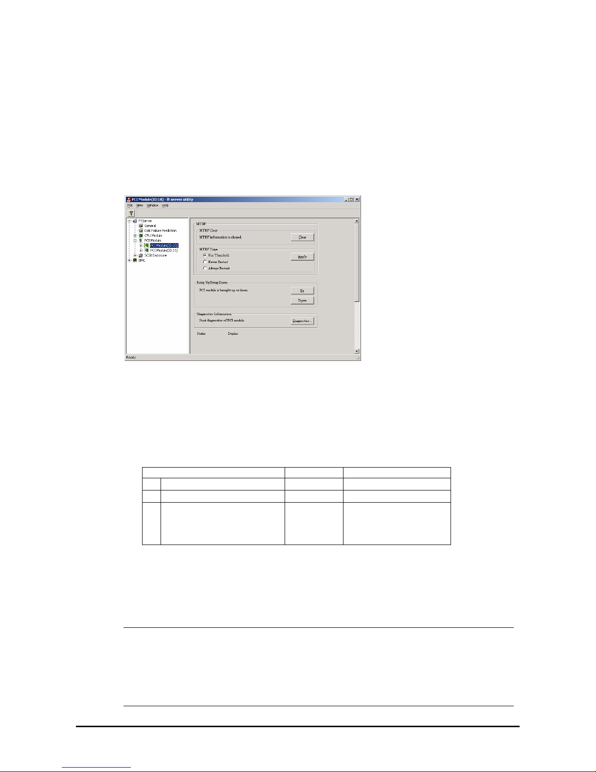
3. Stop the operation of a PCI module using the ft server utility.
Select [Start] - [All Programs] - [NEC ESMPRO Agent] - [ft server utility] to start the ft server utility.
Then, from the ft server utility, select [PCI Module] and then the primary PCI module (*) from the
[FTSever] tree on the left pane, and click [Down] of [Bring Up/Bring Down].
* As for the primary PCI module (*), if the PCI module 0 is primary select [PCI Module(ID:10)]. If the
PCI module 1 is primary, select [PCI Module (ID:11)].
When you stop the operation of the primary PCI module, a failover occurs and the secondary PCI module
becomes the primary module.
The following events or changes occur when stopping the primary PCI module and the module fails over:
z The screen temporarily blacks out and then displayed again.
z The following message will appear from the taskbar:
Windows - FT Orphaning: A disk that is part of a fault-tolerant volume can no longer be accessed.
* The message denotes that the mirror volumes of the hard disk stored in the disconnected PCI
module are released.
* The message will not appear if disks are duplicated by the RDR function.
z Indications of PCI modules’ status LEDs change as follows:
[Indications of status LEDs]
LED Secondary* Primary*
1
CPU/IO module status LED1 Amber -
2
CPU/IO module status LED2 - Green blinking
3
DISK ACCESS LED - Amber or Green blinking
(when the disk is
accessed, this LED
illuminates in green)
* The primary and secondary modules after failover
4.
Restart the PCI module.
From the ft server utility, click [Up] of [Bring Up/Bring Down] to the PCI module which was stopped in
the step 3, and the PCI module will be started. Once the PCI module is started, PCI module diagnosis,
mirror volume duplication and PCI module duplication are performed.
IMPORTANT:
If BrightStor ARCserve 2000 or Backup Exec is in st alled, the tape will not be recognized due to the
failover of the PCI module. Thus be sure to stop the services before starting the PCI module.
1. Start [Services] from [Administrative Tools] of [Control Panel].
2. Select a service of backup software.
3-27
Page 79
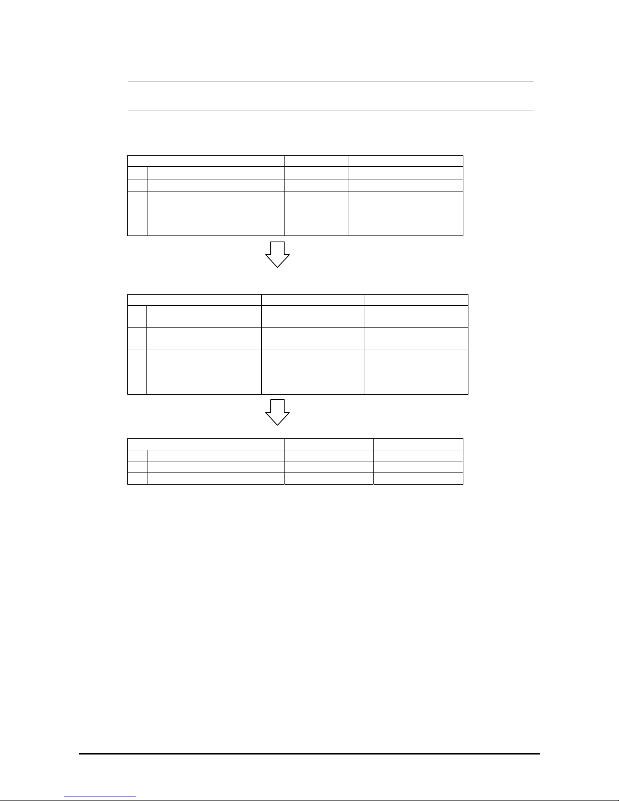
3. Choose “Stop” from the “Action” menu.
4. Repeat 2 and 3 for all services of the backup software.
The PCI modules’ status LEDs changes as shown below:
[Indications of the status LEDs]
Immediately after the PCI module startup until the completion of diagnosis
LED Secondary Primary
1
CPU/IO module status LED1 - -
2
CPU/IO module status LED2 - Green blinking
3
DISK ACCESS LED - Amber or Green blinking
(when the disk is accessed,
this LED illuminates in
green)
When duplication of disks is started after the completion of PCI module diagnosis
* The status of LEDs varies depending on the method of disk d upl i cat i on.
LED Secondary Primary
1 CPU/IO module status
LED1
-
-
2 CPU/IO module status
LED2
Green blinking Green blinking
3 DISK ACCESS LED Amber or Green
blinking (when the disk
is accessed, this LED
illuminates in green)
Amber or Green
blinking (when the disk
is accessed, this LED
illuminates in green)
After the completion of disk duplication and when the PCI modules are duplicated
LED Secondary Primary
1 CPU/IO module status LED1 - 2 CPU/IO module status LED2 Green Green
3 DISK ACCESS LED Green blinking Green blinking
3-28
Page 80
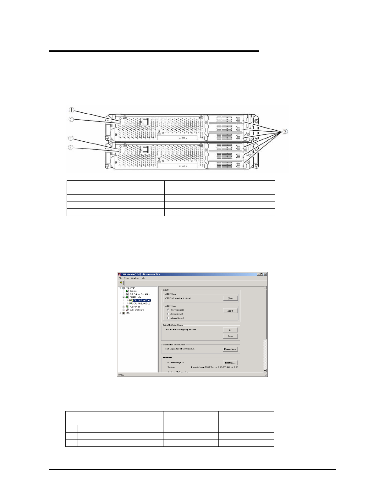
Evaluate Start and Stop of CPU Modules
This section describes how to confirm the continuous system operation after stopping one of the CPU modules.
1.
Confirm that the CPU modules are duplicated.
To check if the CPU modules are duplicated, see the status LEDs of the CPU modules.
[Indicat[Indications of status LEDs when CPU modules are duplicated]
CPU module 0
LED
(Operating)
CPU module 1
(Operating)
1 CPU/IO module status LED1 - 2 CPU/IO module status LED2 Green Green
3 DISK ACESSS LED Green blinking Green blinking
2.
Use the ft server utility to stop the operation of a CPU module to remove.
From [Start], select [All Programs], [NEC ESMPRO Agent] then [ft server utility] to start the ft server utility.
Then, from the ft server utility, select [CPU Module] then the CPU module to stop (*) from the [FTSever] tree on
the left pane, and click [Down] of [Bring Up/Bring Down].
* As for the CPU module to stop, select [CPU Module(ID:0)] to stop CPU module 0, select [CPU Module(ID:1)]
to stop CPU module 1.
When you stop the operation of a CPU module, the indications of the status LEDs change as follows. Below
denotes that the only one CPU module is operating.
[Indications of status LEDs]
CPU module 1
LED
(Stopped)*
CPU module 2
(Operating)
1 CPU/IO module status LED1 Amber 2 CPU/IO module status LED2 - Green blinking
3 DISK ACCESS LED Green blinking Green blinking
z As an example, the indications of when CPU module 0 is stopped are shown.
3-29
Page 81
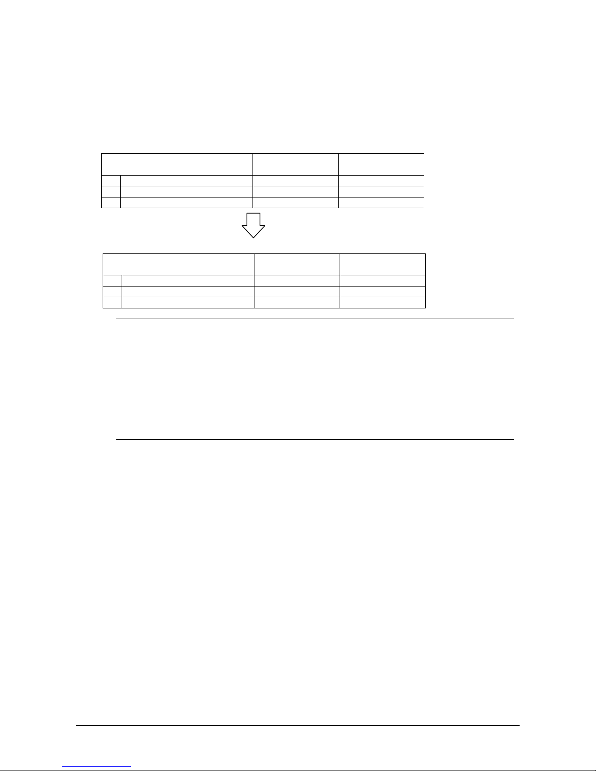
3. Press the start button of the CPU module stopped by ft server utility.
In the ft server utility, select the stopped CPU module and click [Up] of [Bring Up/Bring Down].
Once the CPU module is started, hardware diagnosis and then synchronization of memory (memory copy) are
performed, and the duplication process is completed.
Note that the system is paused temporarily for copying memory during memory synchronization.
[Indications of status LEDs during diagnosis]
LED
CPU module 0
(Started)
CPU module 1
(Operating)
1 CPU/IO module status LED1 - 2 CPU/IO module status LED2 - Green blinking
3 DISK ACCESS LED Green blinking Green blinking
[Indications of status LEDs after completion of duplication]
CPU module 0
LED
(Operating)
CPU module 1
(Operating)
1 CPU/IO module status LED1 - 2 CPU/IO module status LED2 Green Green
3 DISK ACCESS LED Green blinking Green blinking
IMPORTANT:
After duplication is completed, the status of memory will be checked.
Wait until th is process ends to perform the next step (evaluation of start and stop of PCI and CPU modules).
When the process is complete, the following event log will be output:
Source: srabid
Type: Information
Event ID: 4137
Description: Memory consistency check has completed memory scan.
3-30
Page 82

Fault Tolerant Server series SERVICE PROGRAM
CONFIGURATION
Fault Tolerant Server series achieves the duplex system using the following service programs, in addition to dedicated
drivers.
Service program names shown in [Services]:
z Stratus ER Service
z ftSys eService
z ftSys Maintenance and Diagnostics (MAD)
z ftSys RAS
z ftSys RPC Provider
z ftSys SSN
z Windows Management Instrumentation
z SNMP Service
z Alert Manager Main Service
z ESMFSService
z ESMCommonService
z ESRAS Utility Service
z ESMLANService
z ESMPS
The above programs are necessary for the Fault Tolerant Server series operation. Do not stop these services.
When minimizing the number of operating service programs temporarily is required, the following service programs
may be stopped:
Services that can be stopped:
z ESRAS Utility Service
Services required to keep operating
z Stratus ER Service
z ftSys eService
z ftSys Maintenance and Diagnostics (MAD)
z ftSys RAS
z ftSys RPC Provider
z ftSys SSN
z Windows Management Instrumentation
z SNMP Service
z Alert Manager Main Service
z ESMFSService
z ESMCommonService
z ESMLANService
z ESMPS
Make sure to restart the operations of stopped service programs immediately after the backup processes are completed.
3-31
Page 83

Chapter 4
System Configuration
This chapter describes Basic Input Output System (BIOS) configuration.
When you install the Fault Tolerant Server series for the first time or install/remove optional devices, thoroughly read
this chapter for better understanding and correct setups.
4-1
Page 84

SYSTEM BIOS ~ SETUP ~
The SETUP utility is provided to make basic hardware configuration for the server. This utility is pre-installed in the
flash memory of the server and ready to run.
The server is configured with the correct parameters using the SETUP utility and shipped in the best conditions. Thus,
you do not need to use the SETUP utility in most cases. However, you might wish to use the SETUP utility in the cases
described below.
IMPORTANT:
The SETUP utility is intended for system Administrator use only.
The SETUP utility allows you to set a password. The server is provided with two levels of password:
Supervisor and User. With the Supervisor password, you can view and change all system parameters of the
SETUP utility. With the User password, system parameters available for viewing and changing are limited.
Do not set any password before installing the OS.
The server contains the latest version of the SETUP utility. Dialog boxes appearing on your SETUP utility, thus,
may differ from descriptions in this User's Guide. If you find anything unclear, see the online help or ask your
sales agent.
4-2
Page 85
Starting SETUP Utility
Powering on the server starts POST (Power On Self-Test) and displays its check results. If the full screen logo is
displayed, press Esc.
After a few seconds, either of the following messages appears at bottom left on the screen depending on your system
configuration.
Press <F2> to enter SETUP
Press <F2> to enter SETUP or Press <F12> to boot from Network
You may see either of the following messages at bottom left on the screen when POST terminates.
Press <F1> to resume, <F2> to SETUP
Press
F2 to start the SETUP utility and display its Main menu.
If you have previously set a password with the SETUP utility, the password entry screen appears. Enter the password.
Enter password:[ ]
Up to three password entries will be accepted. If you fail to enter the password correctly for three consecutive times, the
server halts. (You can no longer proceed.) Power off the server.
TIPS:
The server is provided with two levels of password: Supervisor and User. With the Supervisor password, you can
view and change all system configurations. With the User password, the system configurations you can view or
change are limited.
4-3
Page 86
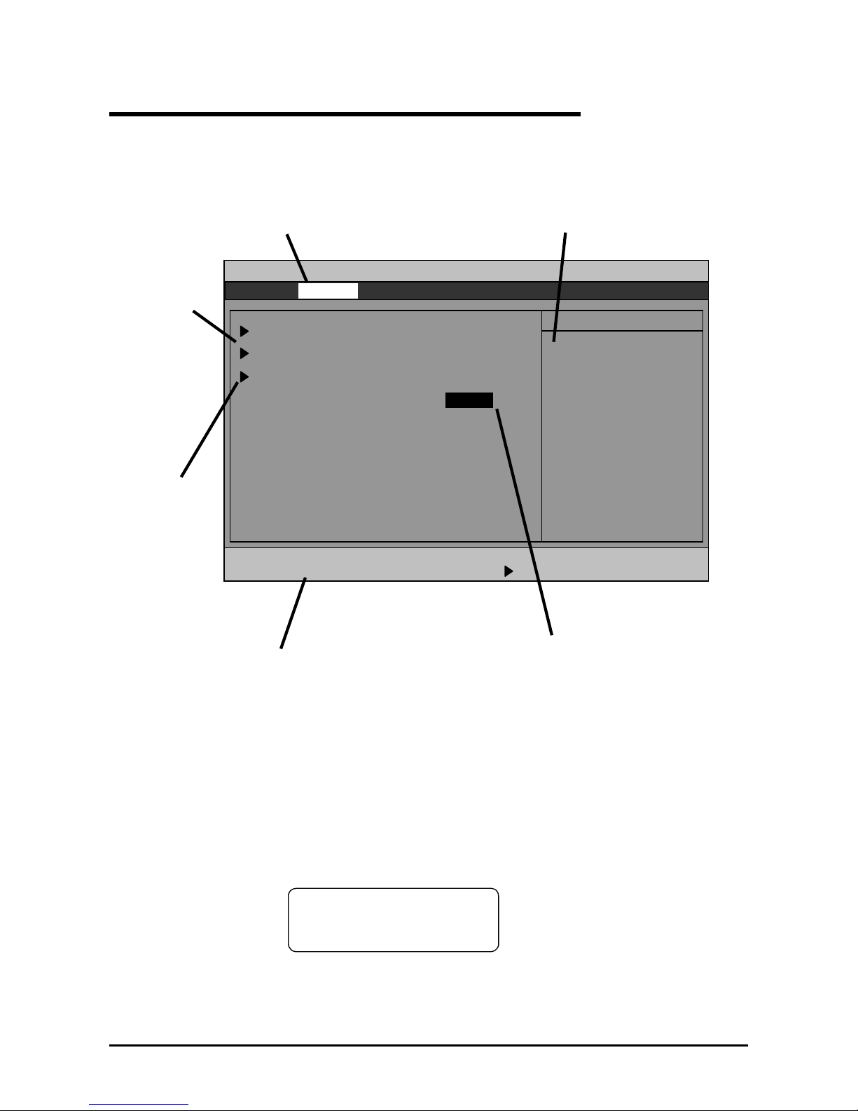
Description of On-Screen Items and Key Usage
Use the following keyboard keys to work with the SETUP utility. (Key functions are also listed at the bottom of the
screen.)
Shows the current menu.
Options to be
configured
Denotes there are
submenus
Online help window
Parameters (selected parameters are
highlighted)
Explanation of keys
Main Advanced Security Server Boot Exit
ftServer Setup
F1 Help ↑↓ Select Item -/+ Change Values F9 Setup Defaults
Esc Exit ←→ Select Menu Enter Select Sub Menu F10 Save and Exit
Advanced Processor Configuration
I/O Device Configuration
Option ROM Configuration
Item Specific Help
Advanced Processor
settings
Boot-time Diagnostic Screen: [Disabled]
HPET [Disabled]
Selects an item on the screen. The highlighted item is currently
selected.
Cursor (↑, ↓):
Selects the Main, Advanced, Security, System Hardware, Boot, or
Exit menu.
Cursor (←, →):
– Changes the value (parameter) of the selected item to the
previous value.
Changes the value (parameter) of the selected item to next value.
+
Enter
Displays a submenu or chooses the selected parameter.
Esc
Displays the previous screen.
Press F1 when you need help on SETUP operations. The help
screen for SETUP operations appears. Press Esc to return to the
previous screen.
F1:
F9:
Shows the following:
Setup Confirmation
Load default configuration now?
[Yes] [No]
If you select “Yes” and then press the Enter key, all items in the
setup are set to default values. If you select “No” and then press
either the
Enter
or Esc key, the status before pressing the F9
key is restored.
4-4
Page 87

Shows the following:
F10:
If you select “Yes” and then press the Enter key, the setup will
complete with all changes you have made saved. If you select
“No” and then press either the
Enter or Esc key, the status
before pressing the F10 key is restored.
4-5
Page 88

Configuration Examples
The following describes examples of configuration required to use software-link features or for system operations.
UPS
To link power supply with the UPS
To power on the server when power is supplied from the UPS
Select [Server] - [AC-LINK] - [Power On].
To keep the server off-powered even when power is supplied from the UPS if the POWER switch was used to
power off
Select [Server] - [AC-LINK] - [Last State].
To keep the server off-powered even when power is supplied from the UPS
Select [Server] - [AC-LINK] - [StayOff].
Keyboard
To set Num Lock and key repeat
Select [Advanced] - [I/O Device Configuration] - [NumLock]
Security
To set passwords on the BIOS level
Select [Security] - [Set Supervisor Password] and enter a password.
Select [Security] - [Set User Password] and enter a password.
Set Supervisor password first, then User password.
Optional PCI–related devices
To enable Option ROM of the PCI card (option) installed on the server
Select [Advanced] - [Option ROM Configuration] - [PCI Slot n (….)] - [Enabled].
n: Slot number to install the board
Boot
To change the boot order of devices connected to the server
Select [Boot] and specify the boot order.
To display POST check results
Select [Advanced] - [Boot-time Diagnostic Screen] - [Enabled].
You can also press
Esc while the logo is on the screen to display POST check results.
To control from the HW console
Remote operation via Serial
Select [Server] - [Console Redirection], and make necessary settings.
4-6
Page 89

Memory
To check the installed memory (DIMM) status:
Select [Advanced] - [System Memory] and [Extended Memory] and check the status indications.
Saving the Configuration Data
To save the BIOS configuration data
Select [Exit] - [Exit Saving Changes]
To discard changes to the BIOS configuration data
Select [Exit] - [Exit Discarding Changes]
To restore the default BIOS configuration data (the data may differ from the factory-setting)
Select [Exit] - [Load Setup Defaults].
4-7
Page 90
Menu and Parameter Descriptions
The SETUP utility has the following six major menus:
Main
Advanced
Security
Server
Boot
Exit
To configure detailed settings of functions, select a submenu from the above menus. Below describes configurable
functions and parameters and the factory settings displayed in the screen for each menu.
Main
Start the SETUP utility to display the Main menu.
When you select a menu with the “►” mark and press the Enter key, its submenu appears.
<Example>
Main Advanced Security Server Boot Exit
ftServer Setup
F1 Help ↑↓ Select Item -/+ Change Values F9 Setup Defaults
Esc Exit ←→ Select Menu Enter Select Sub Menu F10 Save and Exit
System Time: [16:54:28]
System Date: [05/07/2007]
CPU Speed 2.70 GHz
Physical CPUs 1
System Memory 640 KB
Extended Memory 2047 MB
Cache Ram 4096 KB
SATA AHCI Enable [Disabled]
Item Specific Help
<Tab>, <Shift-Tab>, or
<Enter> selects field.
4-8
Page 91
Available options in the Main and descriptions are listed below.
Option Parameter Description
System Time HH:MM:SS Specify the system time.
System Date MM/DD/YYYY Specify the system date.
CPU Speed XXXX MHz Displays the processor clock frequency.
Physical CPUs X Displays the number of processor installed.
System Memory XXXX KB Displays the size of system memory.
Extended Memory XXXX MB Displays the size of extended memory.
Cache Ram XXXX KB Displays the capacity of LS cache.
SATA AHCI
Enable
[Disabled]
Enabled
Specify whether or not to enable AHCI mode.
[ ] factory - set
IMPORTANT:
Check and adjust the system clock before operation in the following conditions.
- After transporting the equipment
- After storing the equipment
- After the equipment halt under the conditions which is out of the guranteed environment conditions (Temperature:
10 to 35°C, Humidity: 20 to 80%).
Check the system clock once in a month. It is recommended to operate the system clock using a time server (NTP
server) if it is installed on the system which requires high level of time accuracy. If the system clock goes out of
alignment remarkably as time goes by, though the system clock adjustment is performed, contact your sales agent.
Do not change [SATA AHCI Enable] to [Enabled]. If [Enabled] is specified, BIOS version might not be displayed in
the ft server utility.
4-9
Page 92
Advanced
Move the cursor onto "Advanced" to display the Advanced menu.
There is no configurable item on the Advanced menu screen below. Display each sub menu and make settings on the
sub menu screen. Select an option with the "►" mark and press
Enter to display its submenu.
Main Advanced Security Server Boot Exit
ftServer Setup
F1 Help ↑↓ Select Item -/+ Change Values F9 Setup Defaults
Esc Exit ←→ Select Menu Enter Select Sub Menu F10 Save and Exit
Advanced Processor Configuration
I/O Device Configuration
Option ROM Configuration
Boot-time Diagnostic Screen: [Disabled]
HPET [Disabled]
Item Specific Help
Advanced Processor
settings
See the table below for setup options on the screen.
Option Parameter Description
Boot-time
Diagnostic Screen
Specify whether to display the Power On Self-Test (POST)
screen at start-up. If "Disabled" is selected, the logo appears
while POST is in progress. (To display POST check results,
press Esc.)
[Disabled]
Enabled
HPET [Disabled]
Specify whether or not to enable High Precision Event Timer
feature.
Enabled
[ ]: factory-set
4-10
Page 93
Advanced Processor Configuration
When you select “Advanced Processor Configuration” in the Advanced menu, the following screen appears.
Main Advanced Security Server Boot Exit
ftServer Setup
F1 Help ↑↓ Select Item -/+ Change Values F9 Setup Defaults
Esc Exit ←→ Select Menu Enter Select Sub Menu F10 Save and Exit
Advanced Processor Configuration
Item Specific Help
Execute Disable Bit: [Enabled]
Intel(R) Virtualization Tech. [Enabled]
PECI Interface: [Enabled]
Refer to the table below for information on options.
Option Parameter Description
Execute Disable Bit Specify whether or not to enable Execute
Disable Bit feature.
[Enabled]
Disabled
Intel(R) Virtualization Tech Specify whether or not to enable Intel
Virtualization Technology feature.
[Enabled]
Disabled
PECI Interface Specify whether or not to enable Platform
Environment Control Interface feature.
[Enabled]
Disabled
[ ]: factory-set
4-11
Page 94
I/O Device Configuration
When you select “I/O Device Configuration” in the Advanced menu, the following screen appears. If you select a menu
with the “►” mark and press Enter, its submenu appears.
Main Advanced Security Server Boot Exit
ftServer Setup
F1 Help ↑↓ Select Item -/+ Change Values F9 Setup Defaults
Esc Exit ←→ Select Menu Enter Select Sub Menu F10 Save and Exit
I/O Device Configuration Item Specific Help
Configure Serial Port 1
using options:
[Disabled]
No configuration
[Enabled]
User configuration
[Auto]
BIOS or OS chooses
configuration
NOTE:
Serial Port 1 may not
be routed to the Modem
if a VTM is present.
Serial Port1: [Enabled]
Base I/O address: [3F8/IRQ 4]
Serial Port 1 Connection: [Serial Connector]
Serial Port2: [Enabled]
Base I/O address: [2F8/IRQ 3]
Serial Port2 Sharing [Disabled]
Keyboard Features:
NumLock: [Off]
Refer to the table below for information on options.
Option Parameter Description
Serial Port 1 Specify whether or not to enable Serial Port 1.
Enabled
[Disabled]
Auto
Base I/O address Specify the I/O address and IRQ of Serial Port 1.
[3F8/IRQ4]
2F8/IRQ3
3E8/IRQ4
2E8/IRQ3
Specify Serial Connector or Internal Modem for
Serial Port 1 connection.
Serial Port 1 Connection
[Serial
Connector]
Internal
Modem
Serial Port 2 Specify whether or not to enable Serial Port 2.
Enabled
[Disabled]
Auto
Base I/O address Specify the I/O address and IRQ of Serial Port 2.
3F8/IRQ4
[2F8/IRQ3]
3E8/IRQ4
2E8/IRQ3
Serial Port 2 Sharing Specify whether or not to use Serial Port 2 in
BMC.
Enabled
[Disabled]
Keyboard Features Display only.
NumLock Specify whether or not to enable NumLock at
system startup.
AUTO
On
[Off]
[ ]: factory-set
4-12
Page 95
Option ROM Configuration
When you select “Option ROM Configuration” in the Advanced menu, the following screen appears.
Main Advanced Security Server Boot Exit
ftServer Setup
F1 Help ↑↓ Select Item -/+ Change Values F9 Setup Defaults
Esc Exit ←→ Select Menu Enter Select Sub Menu F10 Save and Exit
Option ROM Configuration Item Specific Help
Enables Embedded SAS
Option ROM to boot
from the device.
Default state: ENABLED
Embedded SAS Option ROM: [Enabled]
Embedded PXE#1 Option ROM: [Enabled]
Embedded PXE#2 Option ROM: [Enabled]
Refer to the table below for information on options.
Option Parameter Description
PCI Slot 1 (upper) Option ROM Enabled
[Disabled]
If “Enabled” is selected, the extended ROM of
the PCI card installed on PCI Slot 3 is initialized.
Note: this option is displayed only when a PCI
card is installed.
PCI Slot 2 (lower) Option ROM Enabled
[Disabled]
If “Enabled” is selected, the extended ROM of
the PCI card installed on PCI Slot 2 is initialized.
Note: this option is displayed only when a PCI
card is installed.
PCI Slot 3 (onboard) Option ROM Enabled
[Disabled]
If “Enabled” is selected, the extended ROM of
the PCI card installed on PCI Slot 1 is initialized.
Note: this option is displayed only when a PCI
card is installed.
Embedded SAS Option ROM [Enabled]
Disabled
If “Enabled” is selected, SAS extended ROM
that is embedded in the motherboard will be
initialized.
Embedded PXE#1 Option ROM [Enabled]
Disabled
If “Enabled” is selected, the extended ROM of
LAN #1 that is embedded in the motherboard
will be initialized.
Embedded PXE#2 Option ROM [Enabled]
Disabled
If “Enabled” is selected, the extended ROM of
LAN #2 that is embedded in the motherboard
will be initialized.
[ ]: factory-set
4-13
Page 96
Security
Move the cursor onto "Security" to display the Security menu.
Main Advanced Security Server Boot Exit
ftServer Setup
F1 Help ↑↓ Select Item -/+ Change Values F9 Setup Defaults
Esc Exit ←→ Select Menu Enter Select Sub Menu F10 Save and Exit
Supervisor Password Is: Unset
User Password Is: Unset
Set Supervisor Password [Enter]
Set User Password [Enter]
Password on boot [Disabled]
Item Specific Help
Supervisor Password
controls access to the
setup utility.
Select "Set Supervisor Password" or "Set User Password" and press Enter to display the following pop-up screen. The
screen below shows when "Set Supervisor Password" is selected.
Set a password on this pop-up screen. Enter a password of up to seven alphanumeric characters and symbols from the
keyboard.
4-14
Page 97
Main Advanced Security Server Boot Exit
ftServer Setup
F1 Help ↑↓ Select Item -/+ Change Values F9 Setup Defaults
Esc Exit ←→ Select Menu Enter Select Sub Menu F10 Save and Exit
Supervisor Password Is: Unset
User Password Is: Unset
Set Supervisor Password [Enter]
Set User Password [Enter]
Password on boot [Disabled]
Item Specific Help
Supervisor Password
controls access to the
setup utility.
Set Supervisor Password
Enter New Password [ ]
Confirm New Password [ ]
IMPORTANT:
User password setup is not available before Supervisor password setup.
Do not set any password before installing the OS.
If you forget your password, contact your sales agent.
See the table below for setup options on the screen.
Option Parameter Description
Indicates Supervisor password setup status (view
only).
Supervisor
Password Is
Unset
Set
User Password
is
Unset Indicates User password setup status (view only).
Set
Press Enter to display the supervisor password
entry screen. This option is available only when
you log into the SETUP utility with the supervisor
password.
Set Supervisor
Password
[Enter]
Press Enter to display the user password entry
screen. With a user password, accessing the
SETUP menus is restricted.
Set User
Password
[Enter]
Password on
boot
Specify whether to request a password entry at
boot-up. User password setup is required
beforehand.
[Disabled]
Enabled
[ ]: factory-set
IMPORTANT:
If you have logged in SETUP by using the Supervisor Password, you can check and change all settings. If you have
logged in SETUP by using User Password, you see the settings but cannot make changes on the settings except
System Time, System Date and User Password of Main.
4-15
Page 98
Server
Move the cursor onto [Server] to display the Server menu.
The following describes options you can configure in the Server menu and their functions.
Select an option with the "►" mark and press Enter to display its submenu.
Refer to the table below for information on options.
Main Advanced Security Server Boot Exit
ftServer Setup
F1 Help ↑↓ Select Item -/+ Change Values F9 Setup Defaults
Esc Exit ←→ Select Menu Enter Select Sub Menu F10 Save and Exit
System Management
Console Redirection
Event Log Configuration
Monitoring Configuration
Post Error Pause: [Enabled]
AC-LINK: [Last State]
Power On Delay Time: [180]
Item Specific Help
Additional setup
menu to view
server management
features.
Option Parameter Description
Post Error
Pause
Set whether or not to pause POST at the end
of POST if an error has occurred during
POST execution.
Disabled
[Enabled]
Specify the AC LINK feature by selecting the
status of the power supply unit of the server
when the AC power supply restarts. (See the
following table for details.)
AC LINK Stay Off
[Last State]
Power On
Configure the DC ON delay time if AC LINK
is set to “Power On” or “Last State” (unit:
second).
Power ON
Delay Time
[180]-255(s)
[ ]: factory-set
The table below lists how selections for "AC LINK" determine the power status of the server when the power supply to
the server restarts.
Parameter
State before powered off
Stay Off Last State Power On
In service Off On On
Out of service (DC power: Off) Off Off On
Forced shutdown * Off Off On
* Pressing the POWER switch for over four seconds shuts down the power to the server.
System Management
Select "System Management" on the Server menu and press
Enter to display the following screen.
4-16
Page 99
〈Example〉
Main Advanced Security Server Boot Exit
ftServer Setup
F1 Help ↑↓ Select Item -/+ Change Values F9 Setup Defaults
Esc Exit ←→ Select Menu Enter Select Sub Menu F10 Save and Exit
System Management Item Specific Help
All items on this menu
cannot be modified in
user mode. If any
items require changes,
please consult your
system Supervisor.
BIOS Version: 2.1:44
Board Part #: 243-632791
Board Serial #: 113108030768
System Part #: XXXXX-XXXX
System Serial #: 9072543618
Chassis Part #: 243-535509
Chassis Serial #: 01
BMC Device ID: 26
BMC Device Rev: 01
BMC Firmware Rev: 0E.25
SDR Rev: SDR Version 00.10
PIA Rev: 01.10
ASIC Rev: 2023
SMM Rev: 00.25
See the table below for setup options on the screen.
Option Parameter Description
BIOS Version Displays the BIOS version.
Board Part Number Displays the board information.
Board Serial Number Displays the board information.
System Part Number Displays the system information.
System Serial Number Displays the system information.
Chassis Part Number Displays the chassis information.
Chassis Serial Number Displays the chassis information.
BMC Device ID
Displays the BMC information.
BMC Device Revision
Displays the BMC information.
BMC Firmware Revision
Displays the BMC information.
SDR Revision
Displays the revision of SDR (sensor
device information).
PIA Revision
Displays the PIA (plat form information)
revision.
ASIC Rev
Displays the firmware information of the
fault-tolerant chipset.
Displays the firmware information of
System Management.
SMM Rev
[ ]: factory-set
4-17
Page 100
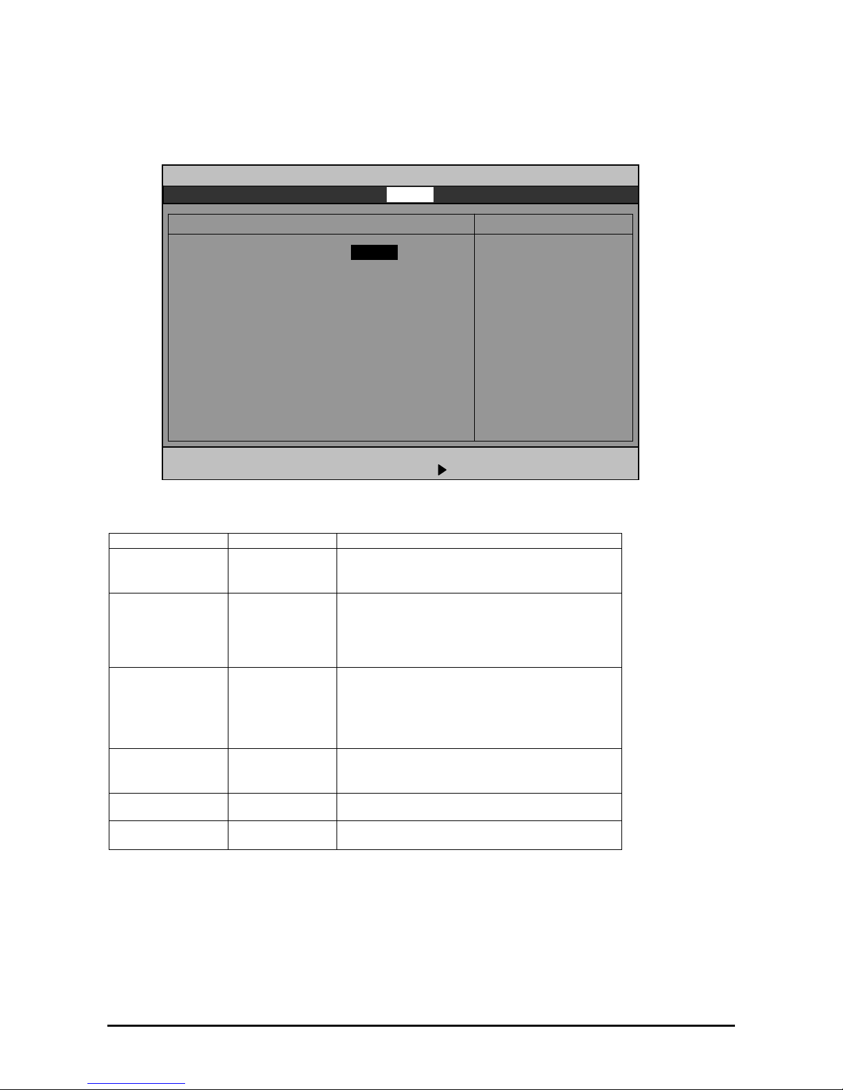
Console Redirection
Select "Console Redirection" on the Server menu and press
Enter to display the following screen.
Main Advanced Security Server Boot Exit
ftServer Setup
F1 Help ↑↓ Select Item -/+ Change Values F9 Setup Defaults
Esc Exit ←→ Select Menu Enter Select Sub Menu F10 Save and Exit
Console Redirection Item Specific Help
If enabled, it will
use a port on the
motherboard.
Com Port Address [Disabled]
Baud Rate [19.2K]
Console Type [PC ANSI]
Flow Control [CTS/RTS]
Console connection: [Direct]
Continue C.R. after POST: [Off]
See the table below for setup options on the screen.
Option Parameter Description
Com Port Address
[Disabled] Select a serial port.
Serial Port1
Serial Port2
Select a port rate used for the interface with a
hardware console to be connected.
Baud Rate* 9600
[19.2K]
38.4K
57.6K
115.2K
VT100
Select a console type.
Console Type*
VT100, 8bit
PC-ANSI, 7bit
[PC-ANSI]
VT100+
VT-UTF8
Flow Control* None
Select a flow control method.
XON/XOFF
[CTS/RTS]
[Direct] Select a connector.
Console Connection
Via modem
[Off] Specify whether or not to continue Console
Redirection after OS is loaded.
Continue C.R. after
POST
On
[ ]: factory-set
4-18
 Loading...