

Page 1

()
■ ■ ■ ■ ■ ■ ■
■ ■ ■ ■ ■ ■ ■
■ ■ ■ ■ ■ ■ ■
■ ■ ■ ■ ■ ■ ■
■ ■ ■ ■ ■ ■ ■
■ ■ ■ ■ ■ ■ ■
■ ■ ■ ■ ■ ■
■
■ ■ ■ ■ ■ ■ ■
■ ■ ■ ■ ■ ■ ■
■ ■ ■ ■ ■ ■ ■
■ ■ ■ ■ ■ ■ ■
■ ■ ■ ■ ■ ■ ■
■ ■ ■ ■ ■ ■ ■
■ ■ ■ ■ ■ ■ ■
User Guide
NovaScale R480 E1
Page 2

2
PROPRIETARY NOTICE AND LIABILITY DISCLAIMER
The information disclosed in this document, including all designs and related materials, is the valuable
property of NEC Computers and/or its licensors. NEC Computers and/ or its licensors, as appropriate,
reserve all patent, copyright and other proprietary rights to this document, includi ng all design,
manufacturing, reproduction, use, and sales rights thereto, except to the extent said rights are expressly
granted to others.
To allow for design and specification improvements, the information in this document is subject to change at
any time, without notice. Reproduction of this document or portions thereof without prior written approval of
NEC Computers is prohibited.
The Bull product(s) discussed in this document are warranted in accordance with the terms of the Warranty
Statement accompanying each product. However, actual performance of each product is dependent upon
factors such as system configuration, customer data, and operator control. Since implementation by
customers of each product may vary, the suitability of specific product configurations and applications must
be determined by the customer and is not warranted by Bull.
rev 1.0 October 2007
Copyright 2007
NEC Computers S.A.S.
All Rights Reserved
Page 3

3
CONTENTS
Chapter 1 ...........................................................................................................................1-1
Notes on Using Your Server............................................................................................1-1
Warning Labels ............................................................................................................................1-2
Safety Notes.................................................................................................................................1-3
General.....................................................................................................................................1-3
Notes on Installing and Accessing the Rack Cabinet...............................................................1-4
Power Supply and Power Cord Use.........................................................................................1-5
Installation, Relocation, Storage, and Connection...................................................................1-6
Cleaning and Working with Internal Devices..........................................................................1-8
During Operation.....................................................................................................................1-9
For Proper Operation..................................................................................................................1-10
Third party Transfer................................................................................................................... 1-11
Consumables.............................................................................................................................. 1-12
Disposal of the Server................................................................................................................ 1-12
User Support...............................................................................................................................1-14
Chapter 2 ...........................................................................................................................2-1
General Description..........................................................................................................2-1
Overview......................................................................................................................................2-2
T op View..................................................................................................................................2-3
Front View...............................................................................................................................2-4
Front View (with Front Bezel Removed)................................................................................. 2-5
Front View (Switches and LEDs)............................................................................................ 2-6
Rear Vie w ................................................................................................................................2-7
Internal View............................................................................................................................2-8
Base Board...............................................................................................................................2-9
Memory Board.......................................................................................................................2-10
I/O Riser Board......................................................................................................................2-10
SAS Riser Board....................................................................................................................2-11
Standard Features.......................................................................................................................2-12
Power Supplies ......................................................................................................................2-13
Peripheral Bays......................................................................................................................2-13
Memory Mirroring Feature....................................................................................................2-14
System Cooling......................................................................................................................2-15
System Board Features ..........................................................................................................2-15
Security..................................................................................................................................2-18
EXPRESSBUILDER.............................................................................................................2-19
NEC ESMPRO ......................................................................................................................2-20
Maintenance T ools................................................................................................................. 2-20
System Diagnostic Utility......................................................................................................2-20
NEC DianaScope...................................................................................................................2-20
Using Y our Server......................................................................................................................2-21
Front Bezel.............................................................................................................................2-21
POWER/SLEEP Switch.........................................................................................................2-22
POST......................................................................................................................................2-23
Floppy Disk Drive .................................................................................................................2-26
CD-RW/DVD-ROM Drive....................................................................................................2-26
Chapter 3 ...........................................................................................................................3-1
Setting Up Your Server.....................................................................................................3-1
Page 4

4
Setup Flow ...................................................................................................................................3-2
Selecting a Site.............................................................................................................................3-3
Installing or Removing the Server into/from the Rack............................................................3-6
Checking Components.............................................................................................................3-7
Required T o ols......................................................................................................................... 3-7
Installation Procedure..............................................................................................................3-8
Removal Procedure................................................................................................................ 3-15
Connecting Peripheral Devices.................................................................................................. 3-17
Connecting the Power Cord .......................................................................................................3-19
Turning On the Server................................................................................................................3-21
Installing the Operating System.................................................................................................3-23
Installing the Utilities.................................................................................................................3-23
Making Backup Copies of the System Information................................................................... 3-23
Chapter 4 ...........................................................................................................................4-1
Configuring Y our Server.................................................................................................. 4-1
System BIOS ~ SETUP ~.............................................................................................................4-1
Starting the SETUP Utility.......................................................................................................4-2
Description on On-Screen Items and Key Usage.....................................................................4-3
Configuration Examples ..........................................................................................................4-4
Menus and Parameters Descriptions........................................................................................4-9
RAID System Configuration......................................................................................................4-35
RAID......................................................................................................................................4-35
Features of the Onboard RAID Controller (MegaRAID ROMB)..........................................4-41
Before Using WebBIOS.........................................................................................................4-46
Using W ebBIOS.....................................................................................................................4-48
Configuring a Virtual Disk.....................................................................................................4-59
Operation of the Various Features..........................................................................................4-75
WebBIOS and Universal RAID Utility..................................................................................4-84
Onboard RAID Controller Battery (MegaRAID ROMB)......................................................4-86
Configuring the Base Board Jumpers.........................................................................................4-87
Clearing CMOS Data............................................................................................................. 4-88
Clearing Password .................................................................................................................4-88
Chapter 5 ...........................................................................................................................5-1
Installing the Operating System with Express Setup...................................................5-1
About Express Setup....................................................................................................................5-2
Microsoft Windows Server 2003..................................................................................................5-3
Notes on the Windows Installation ..........................................................................................5-3
Setup Flow...............................................................................................................................5-6
Installing Windows Server 2003..............................................................................................5-7
Installing and Setting the Device Drivers.............................................................................. 5-15
Solving Problems Settings.....................................................................................................5-21
Installing Maintenance Utilities.............................................................................................5-24
Updating the System - Applying Service Pack -.................................................................... 5-24
Making Backup Copies of System Information.....................................................................5-24
Installing with the OEM-FD for Mass Storage Device.......................................................... 5-25
Chapter 6 ...........................................................................................................................6-1
Installing and Using Utilities............................................................................................6-1
EXPRESSBUILDER ...................................................................................................................6-2
Autorun Menu..........................................................................................................................6-4
Parameter File Creator .................................................................................................................6-5
Parameters File ........................................................................................................................6-5
Page 5

5
NEC ESMPRO........................................................................................................................... 6-15
Functions and Features ..........................................................................................................6-15
NEC DianaScope........................................................................................................................6-16
Universal RAID Utility.............................................................................................................. 6-17
Setup with Express Setup.......................................................................................................6-17
Manual Setup.........................................................................................................................6-17
Using the Universal RAID Utility via the Network............................................................... 6-17
Chapter 7 ...........................................................................................................................7-1
Maintenance......................................................................................................................7-1
Making Backup Copies................................................................................................................7-1
Cleaning .......................................................................................................................................7-2
Cleaning the Server..................................................................................................................7-2
Cleaning the Inside ..................................................................................................................7-3
Cleaning the Keyboard/Mouse.................................................................................................7-4
Cleaning the Optical Disc Drive..............................................................................................7-5
Maintenance T ools.......................................................................................................................7-6
Starting Maintenance Tools......................................................................................................7-6
Function of Maintenance Tools................................................................................................7-8
Maintenance T ools with Remote Console................................................................................7-9
System Diagnostics.................................................................................................................... 7-10
Test Items...............................................................................................................................7-10
Startup and Exit of System Diagnostics.................................................................................7-10
Relocating/Storing the Server.....................................................................................................7-13
Chapter 8 ...........................................................................................................................8-1
Troubleshooting................................................................................................................8-1
System V iewers............................................................................................................................ 8-2
LED..............................................................................................................................................8-3
POWER/SLEEP LED.............................................................................................................. 8-3
STATUS LED ..........................................................................................................................8-4
DISK ACCESS LED................................................................................................................8-6
LAN ACCESS LED................................................................................................................. 8-6
UID LED .................................................................................................................................8-7
Power Unit LED ......................................................................................................................8-8
Fan Error LED......................................................................................................................... 8-9
Access LED ...........................................................................................................................8-10
Hard Disk Drive LED (DISK LED).......................................................................................8-11
LAN Connector LEDs ...........................................................................................................8-12
PCI Slot LEDs .......................................................................................................................8-13
Error Messages........................................................................................................................... 8-14
Error Messages after Power-on..............................................................................................8-14
POST Error Messages............................................................................................................8-15
Beep Codes............................................................................................................................ 8-26
Error Messages on the V irtual LCD.......................................................................................8-27
Solving Problems .......................................................................................................................8-40
Problems with the Server.......................................................................................................8-40
Problems with Windows........................................................................................................ 8-47
Problems with EXPRESSBUILDER.....................................................................................8-50
Problems with Express Setup.................................................................................................8-51
Error Message during RAID System Configuration.............................................................. 8-52
Error with the Battery of the Onboard RAID Controller (MegaRAID ROMB)....................8-53
Problems with Windows Autorun Menu................................................................................ 8-54
Collecting the Event Log............................................................................................................8-55
Collect the Configuration Information.......................................................................................8-56
Collecting Dr. Watson Diagnostic Information..........................................................................8-57
Page 6

6
Memory Dump...........................................................................................................................8-57
Preparing for Memory Dumping............................................................................................8-57
Saving the Dump File............................................................................................................8-58
Recovery for Windows Ser v er 2003 x64 Editions and Windows Server 2003 ..........................8-58
Remote Management Feature.....................................................................................................8-59
Changing the Management LAN Settings.............................................................................8-59
Resetting the Server ...................................................................................................................8-60
Forced Shutdown........................................................................................................................8-61
Chapter 9 ...........................................................................................................................9-1
Upgrading Y our Serv er.....................................................................................................9-1
Safety Notes.................................................................................................................................9-1
Anti-static Measures.....................................................................................................................9-2
Preparing for Installation and Removal........................................................................................9-2
Device Installation or Removal Procedure...................................................................................9-3
2.5-inch Hard Disk Drive.........................................................................................................9-3
Power Supply Unit...................................................................................................................9-8
Server ~ Pulling Out from the Rack Cabinet ~......................................................................9-10
Top Cover ..............................................................................................................................9-12
5-inch Device .........................................................................................................................9-14
PCI Board ..............................................................................................................................9-16
Memory Board.......................................................................................................................9-41
DIMM....................................................................................................................................9-45
Processor................................................................................................................................ 9-53
Appendix A........................................................................................................................A-1
Specifications ...................................................................................................................A-1
Appendix B........................................................................................................................B-1
Other Precautions.............................................................................................................B-1
Transfer Rate of the On-board LAN Controller...................................................................... B-1
Server Management Software................................................................................................. B-1
Floppy Disk............................................................................................................................. B-1
Using a Client Machine Which Has a CD Drive .................................................................... B-1
CD/DVD-ROM....................................................................................................................... B-2
Tape Media ............................................................................................................................. B-2
Keyboard................................................................................................................................. B-3
Mouse ..................................................................................................................................... B-3
Appendix C........................................................................................................................C-1
IRQ and I/O Port Address.................................................................................................C-1
Appendix D........................................................................................................................D-1
Installing Windows Server 2003 x64 Editions................................................................D-1
Before Installing Windows Server 2003 x64 Editions................................................................ D-1
Optional Boards Supported by EXPRESSBUILDER.............................................................D-1
Updating the System...............................................................................................................D-1
Re-installing to the Hard disk drive which has been upgraded to Dynamic Disk................... D-1
MO Device..............................................................................................................................D-1
Media such as DAT.................................................................................................................D-1
Page 7

7
About the System Partition Size.............................................................................................D-2
Installing Windows Server 2003 x64 Editions............................................................................ D-3
Creating "Windows Server 2003 x64 Edition OEM-Disk for EXPRESSBUILDER"............ D-3
Windows Server 2003 x64 Editions Clean Installation........................................................... D-5
Updating the System - Applying Service Pack -.....................................................................D-7
Driver Installation and Advanced Settings................................................................................ D-11
PROSet ................................................................................................................................. D-11
Network Driver.....................................................................................................................D-12
Optional Network Board Driver
(1000BASE-T 2ch/1000BASE-T 4ch/1000BASE-T/10GbE).............................................. D-13
Adapter Fault Tolerance (AFT)/Adaptive Load Balancing (ALB).......................................D-14
Graphics Accelerator Driver................................................................................................. D-15
Installing the Disk Array Controller Drive r (LSILOGIC MEGARAID SAS 8480E)...........D-15
Installing the SAS Controller Driver (LSISAS3443E-R)..................................................... D-15
About Windows Activation...................................................................................................D-16
Settings for the Memory Dump collection (Debug Information).............................................. D-18
Appendix E........................................................................................................................E-1
Installing Windows Server 2003......................................................................................E-1
Before Installing Windows Server 2003.......................................................................................E-1
Optional Boards Supported by EXPRESSBUILDER..............................................................E-1
Installing Service Pack.............................................................................................................E-1
Updating System......................................................................................................................E-1
Re-installing to the Hard disk drive which has been upgraded to Dynamic Disk....................E-1
MO Device...............................................................................................................................E-2
Media such as DAT..................................................................................................................E-2
About the Upgrade to Windows Server 2003 R2.....................................................................E-2
About the System Partition Size..............................................................................................E-2
Installing Windows Server 2003..................................................................................................E-4
Creating "Windows Server 2003 OEM-Disk for EXPRESSBUILDER".................................E-4
Windows Server 2003 Clean Installation.................................................................................E-6
Updating the System - Applying Service Pack -......................................................................E-8
Driver Installation and Advanced Settings.................................................................................E-12
PROSet ..................................................................................................................................E-12
Network Driver......................................................................................................................E-13
Installing Disk Array Controller Driver (LSILOGIC MEGARAID SAS 8480E) .................E-14
Installing SAS Controller Driver (LSISAS3443E-R)............................................................E-14
About Windows Activation....................................................................................................E-15
Available Switch Options for Windows Server 2003 Boot.ini file.........................................E-17
Settings for the Memory Dump collection (Debug Information)...............................................E-18
Appendix F ........................................................................................................................F-1
Product Configuration Record Table..............................................................................F-1
Hardware..................................................................................................................................F-1
Software...................................................................................................................................F-4
Preface........................................................................................................................................ 0-12
About This User's Guide ............................................................................................................0-13
In the Package............................................................................................................................ 0-14
Page 8
8
Keep this User’s Guide at hand for quick reference at anytime necessary.
SAFETY INDICATIONS
Follow the instructions in this User’s Guide for your safety to use the server.
The server contains components with possible danger and hazards that may caused by ignoring warnings. Preventive
actions can be taken against such hazards.
Server components potentially dangerous are indicated with a warning label placed on or around them, and described in
this User’s Guide.
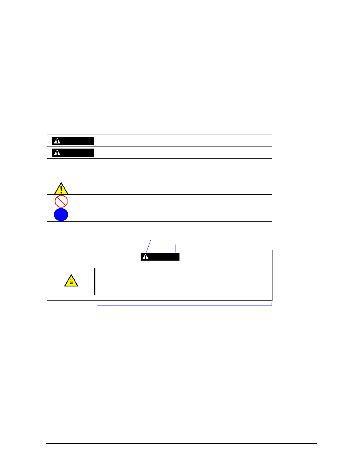
In the User’s Guide or warning labels, "WARNING" or "CAUTION" is used to indicate a degree of danger. These terms
are defined as follows:
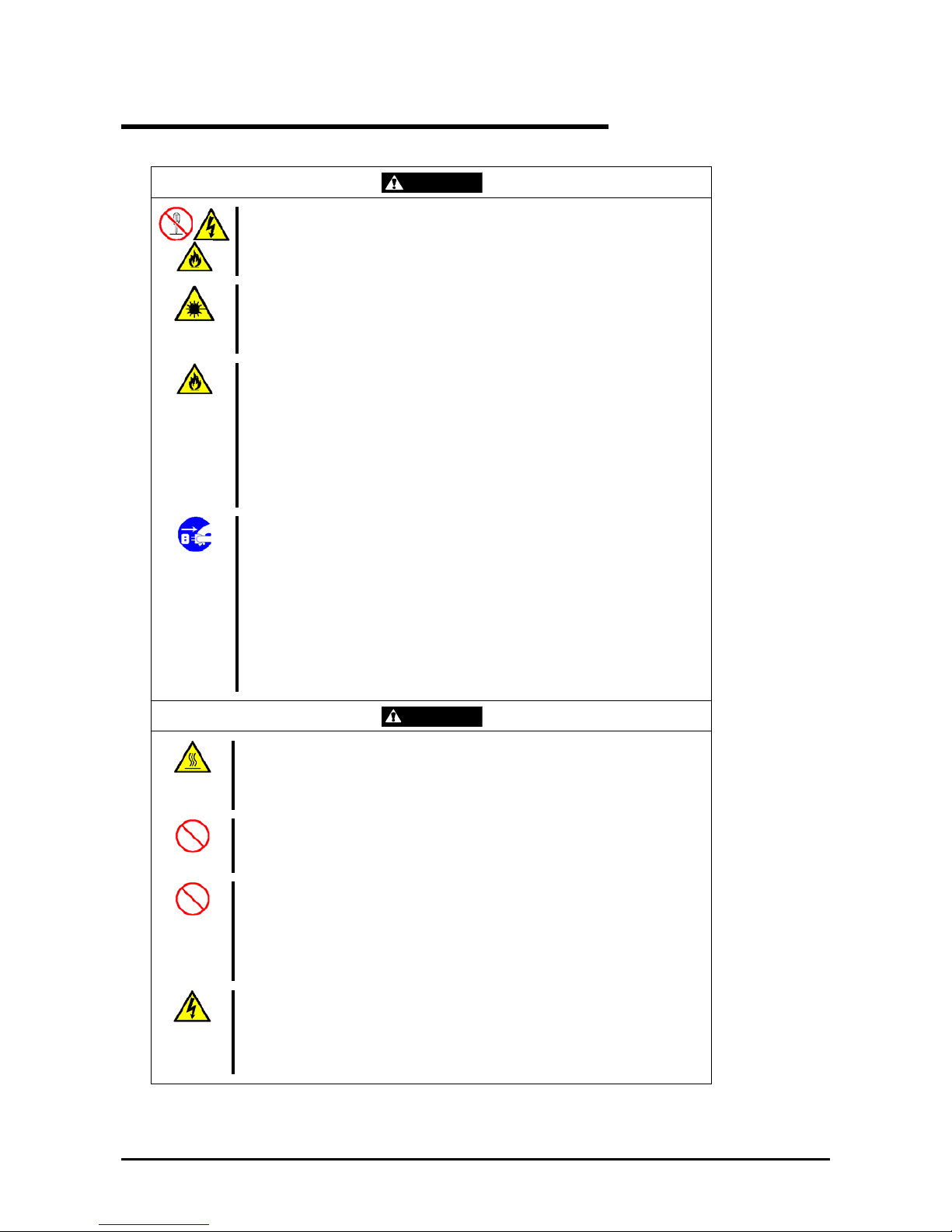
WARNING
Indicates the presence of a hazard that may result in death or serious
personal injury.
CAUTION
Indicates the presence of a hazard that may cause minor personal injury,
including burns, or property damage.
Precautions and notices against hazards are presented with one of the following three symbols. The individual symbols
are defined as follows:
This symbol indicates the presence of a hazard.
An image in the symbol illustrates the hazard type. (Attention)
This symbol indicates prohibited actions. An image in the symbol illustrates a
particular prohibited action. (Prohibited Action)
This symbol indicates mandatory actions. An image in the symbol illustrates a
mandatory action to avoid a particular hazard. (Mandatory Action)
(Example)
Symbol to draw attention
Term indicating a degree of danger
CAUTION
High temperature.
Immediately after the server is powered off, its internal components such as
hard disk drives are very hot. Leave the server until its internal components
fully cool down before installing/removing any component.
Symbol indicating a prohibited
action (may not always be
indicated)
Description of a danger
Page 9
9
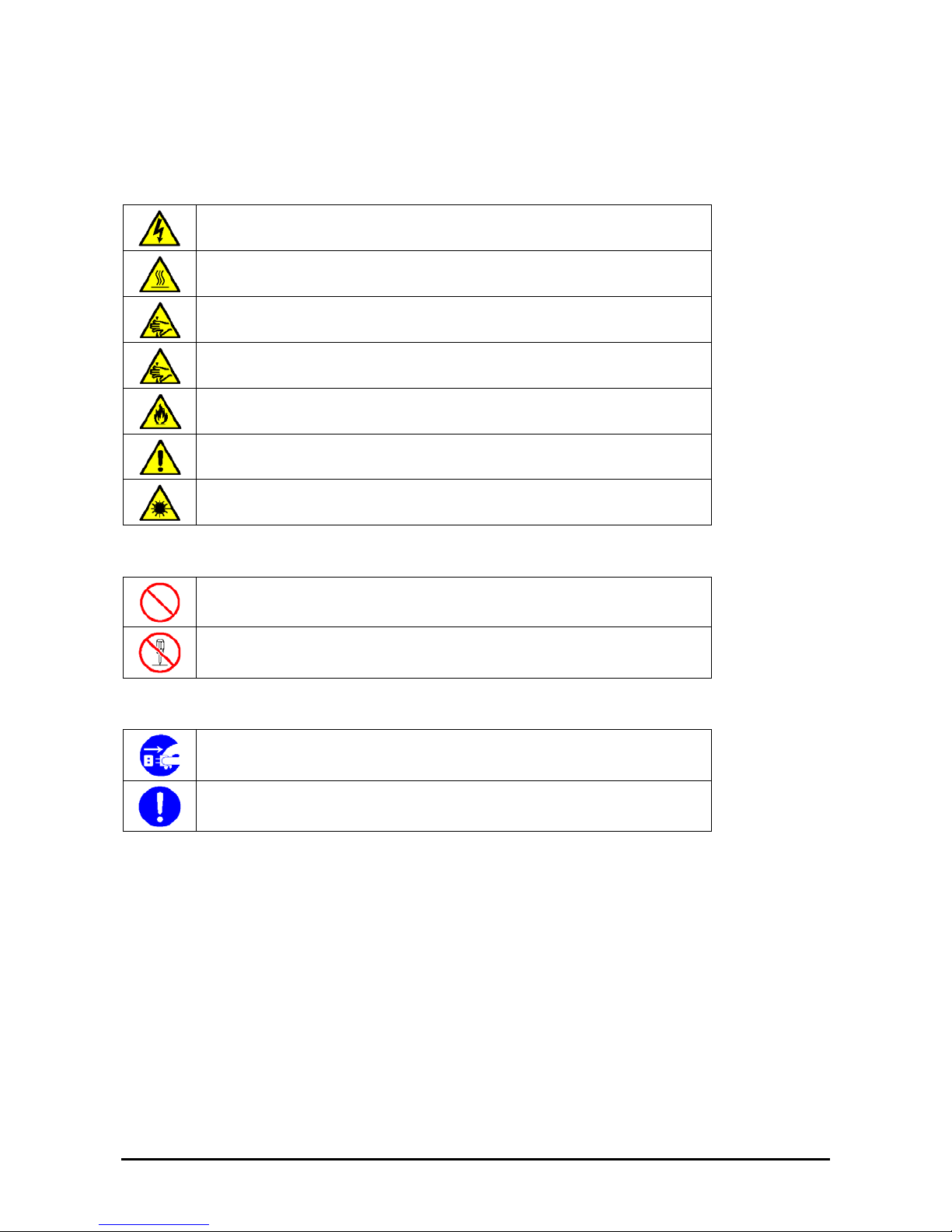
SYMBOLS USED IN THIS USER'S GUIDE AND WARNING LABELS
Attentions
Indicates that improper use may cause an electric shock.
Indicates that improper use may cause personal injury.
Indicates that improper use may cause fingers to be caught.
Indicates that improper use may cause the clip of a hand.
Indicates that improper use may cause fumes or fire.
Indicates a general notice or warning that cannot be specifically identified.
Indicates that improper use may cause loss of eyesight due to laser beam.
Prohibited Actions
Indicates a general prohibited action that cannot be specifically identified.
Do not disassemble, repair, or modify the server. Otherwise, an electric shock or fire
may be caused.
Mandatory Action
Unplug the power cord of the server. Otherwise, an electric shock or fire may be
caused.
Indicates a mandatory action that cannot be specifically identified. Make sure to follow
the instruction.
Page 10

10
SAFETY INDICATIONS BY COLOR OF THE PARTS
Only green areas are available for hot swap or hot plug operation. To avoid electric shock, disconnect all AC cords
before accessing to other parts especially blue area inside the system.
NOTE: This equipment has been tested and found to comply with the limits for a Class A digital device, pursuant to
Part 15 of the FCC Rules. These limits are designed to provide reasonable protection against harmful interference when
the equipment is operated in a commercial environment. This equipment generates, uses, and can radiate radio
frequency energy and, if not installed and used in accordance with the instruction manual, may cause harmful
interference to radio communications. Operation of this equipment in a residential area is likely to cause harmful
interference in which case the user will be required to correct the interference at his own expense.
CE Statement
Warning: This is a Class A product. In domestic environment this product may cause radio interference in which case
the user may be required to take adequate measures (EN55022).
BSMI Statement
CLASS 1
LASER PRODUCT
This system is classified as a CLASS 1 LASER PRODUCT. This label
is located on the internal CD-RW/DVD-ROM drive installed in your
system.
Page 11

11
Trademarks
NEC ESMPRO and EXPRESSBUILDER are trademarks of NEC Corporation.
Microsoft, Windows, Windows Server, and MS-DOS are registered trademarks or trademarks of Microsoft Corporation in the United States and other
countries.
Intel, Pentium, and Xeon are registered trademarks of Intel Corporation.
PCI Express is a trademark of Peripheral Component Interconnect Special Interest Group.
Datalight is a registered trademark of Datalight, Inc.
ROM-DOS is a registered trademark of Datalight, Inc.
AT is a registered trademark of International Business Machines Corporation in the United States and other countries.
Adaptec and its logo is a registered trademark of Adaptec, Inc. of United States.
SCSISelect is a trademark of Adaptec, Inc. of the United States.
LSI, the LSI logo design, iBBU, MegaRAID, and WebBIOS are trademarks or registered trademarks of LSI Corporation of United States.
Adobe, Adobe logo, and Acrobat are trademarks of Adobe Systems Incorporated.
DLT and DLTtape are trademarks of Quantum Corporation of the United States.
All other product, brand, or trade names used in this publication are the trademarks or registered trademarks of their respective trademark owners.
Windows Vista stands for Microsoft® Windows Vista® Business operating system. Windows Server 2003 x64 Editions stands for Microsoft®
Windows® Server 2003 R2, Standard x64 Edition Operating system and Microsoft® Windows® Server 2003 R2, Enterprise x64 Edition operating
system, or Microsoft® Windows® Server 2003, St andard x64 Edition operating system and Microsoft® Windows® Server 2003, Enterprise x64
Edition operating system. Windows Server 2003 stands for Microsoft® Windows® Server 2003 R2, Standard Edition operating system and
Microsoft® Windows® Server 2003 R2, Enterprise Edition operating system, or Microsoft® Windows® Server 2003, Standard Edition operating
system and Microsoft® Windows® Server 2003, Enterprise Edition operating system. Windows XP x64 Edition stands for Microsoft® Windows®
XP Professional x64 Edition operating system. Windows XP stands for Microsoft® Windows® XP Home Edition operating system and Microsoft®
Windows® XP Professional operating system. W i ndows 2000 stands for Microsoft® Windows® 2000 Server operating system and Microsoft®
Windows® 2000 Advanced Server operating system, and Microsoft® Windows® 2000 Professional operating system. Windows NT stands for
Microsoft® Windows NT® Server network operating system version 3.51/4.0 and Microsoft® Windows NT® Workstation operating system version
3.51/4.0. Windows Me stands for Microsoft® Windows® Millennium Edition operating system. Windows 98 stands for Microsoft® Windows®98
operating system. Windows 95 stand s for Microsoft® Windows®95 opera ting system. WinPE stands for Microsoft® Windows® Preinstallation
Environment.
Momentary voltage drop prevention:
This product may be affected by a momentary voltage drop caused by lightning. To prevent a momentary voltage drop,
an AC unint erruptible power supply (UPS) uni t sh ould be used.
Notes:
(1) No part of this manual may be reproduced in any form without the prior written permission of NEC Corporation.
(2) The contents of this User's Guide may be revised without prior notice.
(3) The contents of this User’s Guide shall not be copied or altered without the prior written permission of NEC
Corporation.
(4) All efforts have been made to ensure the accuracy of all information in this User’s Guide. If you notice any part
unclear, incorrect, or omitted in this User’s Guide, contact the service representative where you purchased this
product.
(5) The manufacturer assumes no liability arising from the use of this product, nor any liability for incidental or
consequential damages arising from the use of this User’s Guide regardless of Item (4).
Page 12

12
PREFACE
Welcome to the NovaScale R480 E1 server.
The NovaScale R480 E1 server holds powerful performance and employs the latest technology to implement a
computer for the next generation. With its potential capabilities, the server may be used as the workstation PC that
configures a client-server system and provides high-speed processing and superior reliability.
Read this User’s Guide thoroughly to fully understand the handling of the server and appreciate its functions to the
maximum extent.
Page 13

13
ABOUT THIS USER'S GUIDE
This User’s Guide is a guide for proper setup and use of the server.
This User’s Guide also covers useful procedures for dealing with difficulties and problems that may arise during setup
or operation of the server. Keep this manual for future use.
The following describes how to proceed with this User’s Guide.
How to Use This User's Guide
To help you find the information quickly, this User’s Guide contains the following information:
Chapter 1 Notes on Using Your Server
includes information that requires attention when using the server. Make sure to read this
chapter before setting up and using the server.
Chapter 2 General Description
includes information necessary to use the server, such as names and functions of its
components, handling of the floppy disk and CD-RW/DVD-ROM drives. It also includes
requirements and advisory information for transfer and disposal of the server.
Chapter 3 Setting Up Your Server
tells you how to select a site, unpack the system, assemble the rack-mount subsystem,
make the cable connections, and power on your system.
Chapter 4 Configuring Your Server
tells you how to configure the system and provides instructions for running the BIOS Setup
Utility and the RAID Configuration Utility, which is used to configure the SAS devices in
your system. This chapter also provides information on the base board and I/O riser board
jumper settings.
Chapter 5 Installing the Operating System with Express Setup
describes how to install the operating system.
Chapter 6 Installing and Using Utilities
describes how to install the utilities for the server. It also includes information on using the
attached "EXPRESSBUILDER" DVD.
Chapter 7 Maintenance
provides you with all the information necessary to maintain successful operation of the
server. This chapter also includes a description on relocating and storing the server.
Chapter 8 Troubleshooting
contains helpful information for solving problems that might occur with your system.
Chapter 9 Upgrading Your Server
provides you with instructions for upgrading your system with an additional processor,
optional memory, optional add-in cards, hard disk drives, peripheral devices, and power
supply.
Appendix A Specification
provides specifications for your server.
Appendix B Other Precautions
provides supplementary notes on using the server.
Page 14

14
Appendix C IRQ and I/O Port Address
provides a list of factory-set IRQs and I/O port addresses assigned.
Appendix D Installing Windows Server 2003 x64 Editions
describes how to install Microsoft Windows Server 2003 x64 Editions without using Express
Setup. Using the Express Setup tool is recommended for installing Windows Server 2003
x64 Editions. See Chapter 5 for details.
Appendix E Installing Windows Server 2003
describes how to install Microsoft Windows Server 2003 without using Express Setup.
Using the Express Setup tool is recommended for installing Windows Server 2003. See
Chapter 5 for details.
Appendix F Product Configuration Record Table
provides a table to be filled with your server configuration.
Text Conventions
The following conventions are used throughout this User’s Guide. For safety symbols, see "SAFETY INDICATIONS"
provided earlier.
IMPORTANT:
Items that are mandatory or require attention when using the server.
NOTE:
Notes give important information about the material being
described.
IN THE PACKAGE
The carton contains various accessories, as well as the server itself. See the packing list to make sure that you have
everything and that individual components are not damaged. If you find that any component is missing or damaged,
contact your service representative.
Store the provided accessories in a designated place for your convenience. You will need them to install an
optional device or troubleshoot the server, as well as to set it up.
Make a backup copy of each provided floppy disk, if any. Store the original disk as the master disk in a
designated place, and use its copy.
Improper use of any provided floppy disk or DVD-ROM may alter your system environment. If you find
anything unclear, immediately ask your service representative for help.
Page 15

1-1
Chapter 1
Notes on Using Your Server
This chapter includes the information necessary for the proper and safe operation of your server.
Page 16
1-2
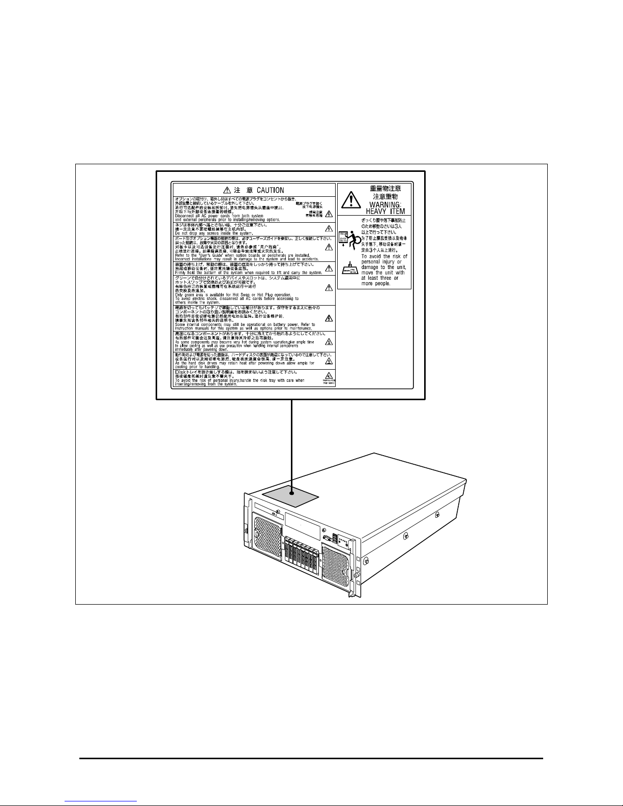
WARNING LABELS
A warning label is attached to the potentially dangerous components or their vicinity in your server to inform the user
that a hazardous situation may arise when operating the server. (Do not intentionally remove or damage any of the
labels.)
If you find any labels totally/partially removed or illegible due to damage, contact your sales representative.
Page 17
1-3
SAFETY NOTES
This section provides notes on using your server safely. Read this section carefully to ensure proper and safe use of the
server. For symbols, see "SAFETY INDICATIONS" provided earlier.
For part names described in the safety instruction chapter in this guide, refer to "Features and Controls" in Chapter 2.
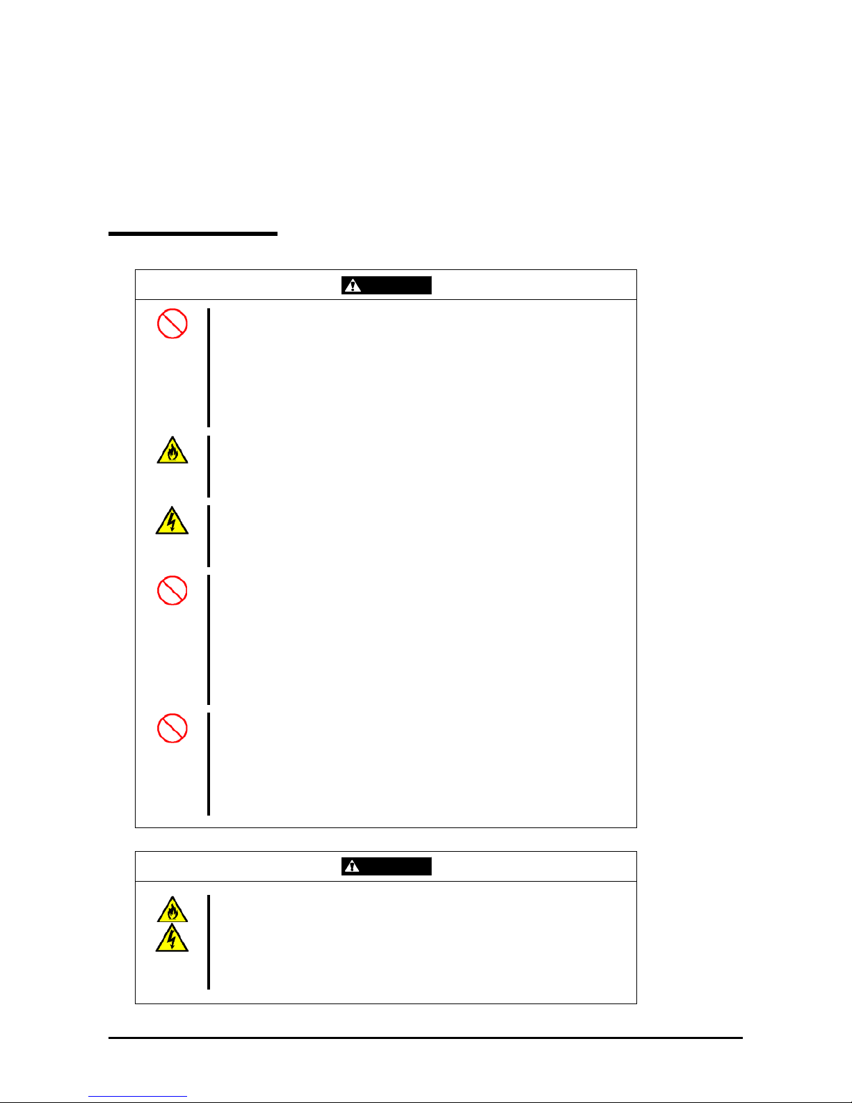
General
WARNING
Do not use the server for services where critical high availability may directly
affect human lives.
Your server is not intended to be used with or control facilities or devices
concerning human lives, including medical devices, nuclear facilities and
devices, aeronautics and space devices, transportation facilities and devices;
and facilities and devices requiring high reliability. The manufacturer assumes
no liability for any accident resulting in personal injury, death, or property
damage if the server has been used in the above conditions.
Do not use the server if any smoke, odor, or noise is present.
If smoke, odor, or noise is present, immediately power off the POWER/SLEEP
switch, disconnect the power plug from the outlet, then contact your service
representative. Using the server in such conditions may cause a fire.
Keep needles or metal objects away from the server.
Do not insert needles or metal objects into the ventilation holes in the server or
the openings in the floppy disk or CD-RW/DVD-ROM drive. Doing so may
cause an electric shock.
Do not use the server in any unapproved place.
Install the server in a standard EIA 19-inch rack cabinet. Do not install the rack
containing the server in an inappropriate environment.
Failure to follow these instructions may cause interferences of various nature to
the server and the other systems installed on the rack. Fires or personal injuries
due to the rack fall may occur. For more information on the place where your
server should be installed and the earthquake-resistant construction for the
rack, refer to the manual attached to the rack or contact your service
representative.
Always install the server in a rack conforming to the relevant standard.
Install the server on a rack conforming to the EIA standard for the server to be
used. Do not use the server if it is installed in any other rack than the standard
EIA 19-inch rack or if it is not installed in a proper rack. Failure to follow these
instructions may cause your server to operate incorrectly and/or personal injury
or damages of the surrounding devices to occur. Contact your service
representative for the racks available for your server.
CAUTION
Keep water or foreign matter away from the server.
Do not let any form of liquid (water etc.) or foreign matter (e.g., pins or paper
clips) enter the server. Failure to follow this warning may cause an electric
shock, a fire, or a failure of the server. When such things accidentally enter the
server, immediately power off the power and disconnect the power plug from
the outlet. Do not disassemble the server. Contact your service representative.
Page 18
1-4
Notes on Installing and Accessing the Rack Cabinet
CAUTION
Do not carry or install the rack cabinet only by a single person.
More than one person is required to carry or install the rack. Failure to follow this
instruction may cause the rack to fall, resulting in personal injuries and/or
surrounding devices to be broken. In particular, a high rack (such as 44U rack) is
unstable if it is not secured using stabilizers.
Make sure that the load is not concentrated in a specific point.
Install stabilizers on the rack so that the total load of the rack and devices mounted
on the rack is not concentrated on a single point, or join several racks together to
distribute the load. Failure to follow this instruction may cause the rack to fall,
resulting in personal injuries.
Do not install components on the rack cabinet only by a single person.
More than one person is required to install parts such as the rack doors and trays.
Failure to follow this instruction may cause some parts to fall, resulting in personal
injuries and/or devices to be broken.
Do not pull out a device from the rack if the rack is unstable.
Always make sure of the stability of the rack before pulling out a device.
Do not leave more than one device pulled out from the rack at the same time.
Pulling out several devices from the rack may cause the rack to fall.
Make sure the wiring of the server does not exceed the rating of the power supply.
To prevent burns, fires, and device damages, the power supplied to the server must
not exceed the rating load of the power branch circuit. The server requires at least
two power cords or up to four power cords (depending on your configuration).
Connect each power cord to each appropriate wall outlet provided with 20A branch
circuit. Contact your electric constructor or the local power company for the
requirements on the wiring and installation of electric facilities.
Maintain reliable earthing
Reliable earthing of the rack-mounted equipment must be maintained. Particular
attention should be given to supply connections other than direct connection to the
branch circuit (e.g. use of power strips).
Page 19
1-5
Power Supply and Power Cord Use
WARNING
Do not hold the power plug with a wet hand.
Do not disconnect/connect the plug if your hands are wet. Failure to follow this
warning may cause an electric shock.
CAUTION
Plug in to a proper power source.
Use a grounded wall outlet of the specified voltage. Using an improper power
source may cause a fire or a power leak.
Do not install the server in a place where you need an extension cord. Using a
cord that does not meet the power specifications of your server may heat up the
cord and cause a fire.
Do not connect the power cord to an outlet that has an illegal number of
connections.
The electric current exceeding the rated flow overheats the outlet, and may
cause a fire.
Insert the power plug into the outlet as far as it goes.
Heat generation resulting from a halfway inserted power plug (imperfect contact)
may cause a fire. Heat will also be generated if cond ensa ti on fo rms on the dusty
blades of the halfway inserted plug, increasing the possibility of fire.
Use only the authorized power cord.
Use only the power cord that comes with your server. Using an unauthorized
power cord may cause a fire if the electric current exceeds the rated flow.
Also observe the following to prevent an electric shock or fire caused by a
damaged cord.
Do not stretch the cord harness.
Do not pinch the power cord.
Do not bend the power cord.
Keep chemicals away from the power cord.
Do not twist the power cord.
Do not place any object on the power cord.
Do not bundle power cords.
Do not alter, modify, or repair the power cord.
Do not secure the power cord with staples or equivalents.
Do not use a damaged power cord. (Replace a damaged power cord with a
new one of the same specifications. Ask your service representative for
replacement.)
Do not use the attached power cord for any other devices or usage.
The power cord that comes with your server is specifically to be connected with
this server, and its safety has been tested. Do not use the attached power cord
for any other purpose. Doing so may cause a fire or an electric shock.
Page 20
1-6
Installation, Relocation, Storage, and Connection
CAUTION
Never attempt to lift the server only by yourself.
Your server weighs 47 kg (depending on its hardware configuration). Carrying
the server only by yourself may strain your back. Hold the server firmly by its
bottom with at least three persons to carry it. Do not hold the front bezel to lift
the server. The front door may disengage from the server, causing personal
injury.
Do not install your server on a rack without its cover.
Failure to follow this instruction may reduce the cooling effect in the server,
resulting in some malfunction and/or dust entering the server, and resulting in a
fire or electric shock.
Do not pinch your finger with rails or other components.
Use a screwdriver or any other tool to press the safety latch release lever on
the rack slide rail. Pressing the levers with your finger may cause an injury.
Do not apply any load on the server when it is pulled out from the rack.
Doing so bends the frame of the server, and consequently, the server cannot
be pushed back into the rack. Placing an object on the server may also cause a
personal injury if the server should fall.
Do not install the server in any place other than the ones specified.
Do not install the server in the following places or any places other than the
ones specified in this manual. Failure to follow this instruction may cause a fire.
a dusty place
a humid place such as near a boiler
a place exposed to direct sunlight
an unstable place
Do not use the equipment in a place where corrosive gases exist.
Make sure not to locate or use the server in the place where corrosive gases
(sulfur dioxide, hydrogen sulfide, nitrogen dioxide, chlorine, ammonia, ozone,
etc) exist.
Also, do not set it in the environment where the air (or dust) includes
components accelerating corrosion (ex. sulfur, sodium chloride) or conductive
metals. There is a risk of a fire due to the corrosion and shorts of an internal
printed board.
Page 21
1-7
CAUTION
Do not connect any interface cable with the power cord of the server plugged to
a power source.
Make sure to power off the server and unplug the power cord from the power
outlet before installing/removing any optional internal device or
connecting/disconnecting any interface cable to/from the server. If you do not
do so, touching an internal device, cable, or connector may cause an electric
shock or a fire resulted from a short circuit.
Do not use any unauthorized interface cable.
Use only the interface cables provided by the manufacturer and locate a proper
device and connector before connecting a cable. Using an authorized cable , or
connecting a cable to an improper destination may cause a short circuit,
resulting in a fire.
Also observe the following notes when using and connecting an interface cable.
Do not use any damaged cable connector.
Do not step on the cable.
Do not place any object on the cable.
Do not use the server with loose cable connections.
Page 22
1-8
Cleaning and Working with Internal Devices
WARNING
Do not disassemble, repair, or alter the server.
Never attempt to disassemble, repair, or alter the server on any occasion other
than the ones described in this manual. Failure to follow this instruction may
cause an electric shock or fire, as well as malfunctions of the server.
Do not look into the CD-RW/DVD-ROM drive.
The laser beam used in the CD-RW/DVD-ROM drive can be harmful to the
eyes. Do not look into or insert a mirror into the drive while the drive is
powered on. The laser beam is invisible, but you may lose your eyesight.
Do not remove the lithium and NiMH batteries.
Your server contains lithium and NiMH batteries. Do not remove or replace the
batteries. If the battery is incorrectly replaced, it may cause an explosion.
Placing the battery close to a fire or in the water may also cause an explosion.
If the server does not operate appropriately because the batteries are dead,
contact your service representative to replace the batteries only with the same
or equivalent type recommended by the manufacturer. Do not disassemble the
server in order to replace or recharge the battery yourself.
Disconnect all the power plugs before accessing the inside of the server or
connecting the peripherals.
The server has two power cords.
Make sure to power off the server and disconnect all the power plugs from a
power outlet before cleaning or installing/removing internal optional devices.
Touching any internal device of the server with its power cords connected to a
power source may cause an electric shock even of the server is powered off.
Disconnect all the power plugs regularly from the outlet and clean them with a
dry cloth. Heat will be generated if condensation forms on a dusty plug, and
may cause a fire.
CAUTION
Hot surface
Immediately after the server is powered off, some of its internal components,
such as the hard disk drives are very hot. Let the internal components fully cool
down before installing/removing any components.
Make sure to complete the board installation.
Always install a board firmly. An incompletely installed board may cause a
contact failure, resulting in smoke or fire.
Protect the unused connectors with the protective cap.
The unused power supply cable connectors are covered with a protective cap
to prevent short circuits and electrical hazards. When removing the power
supply cable connector from the internal devices, attach the protective cap to
the connector. Failure to follow this warning may cause a fire or an electric
shock.
Do not touch any electrical components inside the server during a hot-swap
replacement.
Power flows inside the server while the hot-swap replaceable components (PCI
add-in cards, hard disk drive, cooling fan, and power supply). Do not touch the
electrical components inside the server to avoid an electric shock.
Page 23
1-9
During Operation
CAUTION
Avoid contact with the server during thunderstorms.
Disconnect all the power plugs from the outlet when a thunderstorm is
approaching. If it starts thundering before you disconnect the all power plugs,
do not touch any part of the server including the cables. Failure to follow this
warning may cause a fire or an electric shock.
Keep animals away from the server.
Failure to follow this warning may cause a fire or an electric shock.
Do not place any object on top of the server.
An object placed on top of the server may fall down, resulting in damage to your
property around the server.
Do not remove the cooling fans.
Only a service technician authorized by the manufacturer can remove the
cooling fans from the server.
Page 24

1-10
FOR PROPER OPERATION
Observe the following notes for successful operation of the server. Using the server while ignoring the notes will cause
malfunctions or failures of the server.
Install the server in a place that meets the requirements for successful operation. For more information, see
Chapter 3, "Setting Up Your Server."
Make sure to power off the server before connecting or disconnecting cables between the server and
peripheral devices.
Make sure that the access LED on the server is unlit before turning off the server or ejecting the floppy disk.
The server management logic on your system boa rd monitors and logs system voltage changes. When
plugging the power cord to the system, you may experience a 10 seconds delay between power on and the
time you pressed the POWER/SLEEP switch on the front panel. This is normal system operation and is
required by the server management logic.
If you power off the server, wait at least 30 seconds before powering it back on.
Do not power off the server until characters following the full screen logo have appeared on the screen. It may
take one to five minutes depending on your configuration.
Power off the power and unplug the power cord from the outlet before relocating the server.
Some software include a command allowing you to eject the CD-RW/DVD-ROM drive tray. Make sure that
the front bezel is removed before running the command. Running this command with the front bezel installed
may cause the CD-RW/DVD-ROM drive tray or the media to hit the front bezel, resulting in a failure of the
server
Clean the server on a regular basis. (See Chapter 7 for cleaning.) Regular cleaning proactively can prevent
various failures of the server.
Lightning may cause a momentary voltage drop. To prevent this problem, we recommend you use an
uninterruptible power supply unit.
Check and adjust the system clock before the operation if any of the following conditions is applicable.
– After carrying of the server
– After storage of the server
– After the server entered into the pause state under the following environmental conditions (temperature:
10°C - 35°C, humidity: 20% - 80%)
Check the system clock roughly once per month. If the system clock is installed in a system requir ing high
time precision, we recommended you use a time server (NTP server).
If the system clock is delayed or advanced as time goes by in spite of adjustment, contact your sales agent and
request a maintenance operation.
Store the unit under the approved storage conditions (temperature: -10°C - 55°C, humidity: 20% - 80%,
without condensation) to allow the built-in devices and the unit to operate correctly in the next operation.
Make sure to use the optional devices supported by the server. Some non-supported devices may be physically
installed/connected but cause failures of the server as well as malfunctions of the server.
We recommend you use our genuine products. Some third-party products claim that th ey support our server.
However, repairing the server due to a failure or damage resulting from the use of such third-party products
will be charged.
Playback of disks which do not conform to the CD or DVD standard is not guaranteed.
Power off any cellular phone or pager. Radio interferences may cause malfunctions of the server.
Page 25

1-11
THIRD PARTY TRANSFER
The following must be observed when you transfer (or sell) the server or software provided with the server to a third
party:
Server
Make sure to provide this manual along with the server to a third party.
IMPORTANT: About dat a on the hard disk drive
Be sure to take appropriate measures not to leak important data (e.g., customers'
information or companies' management information) on the removed hard disk drive to any
third parties.
Data seems to be erased when you empty the Windows "Recycle Bin" or execute a "format"
command of the operating system. However, the actual data remains written on the hard
disk drive, and may be restored by special software and used for unexpected purposes.
We strongly recommend that a software or service (both available at stores) for data erasure
is used in order to avoid the troubles explained above. For more information on data erasure,
ask your sales representative.
Provided software
To transfer or sell any software application that comes with the server to a third party, the following requirements must
be satisfied:
All the provided software applications must be transf erred and no backup copies must be retained.
The transfer requirements listed in the "Software License Agreement" that comes with each software
application must be satisfied.
The software applications that are not approved for transfer must be uninstalled before transferring the server.
Page 26

1-12
CONSUMABLES
Your server contains some components that are only good for a limited period of time and require replacement, such as
batteries, fans, the internal CD-RW/DVD-ROM drive, the floppy disk drive, and the mouse. For stable operation of the
server, we recommend you replace these components on a regular basis. Ask your service representative for
replacement or more information on the product lifespan.
DISPOSAL OF THE SERVER
Dispose of the server, all the internal devices, floppy disks, and DVD/CD-ROMs according to your national laws and
regulations. Also dispose of the power cord provided with the server so that it cannot be used with other devices.
IMPORTANT: For disposal (or replacement) of the battery on the baseboard of the server,
consult with your service representative.
NOTE: If the real-time clock battery on the base board has reached the end of its life, the
following message appears on the display while running the POST. Contact your service
representative to replace the battery.
0250 System battery is dead –Replace and run SETUP
Page 27
1-13
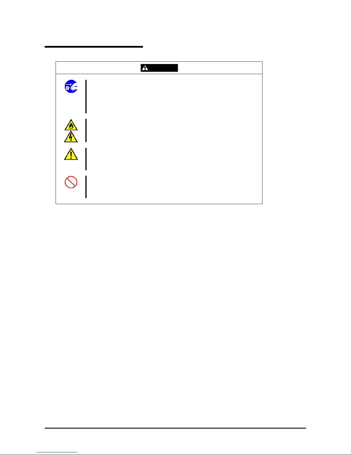
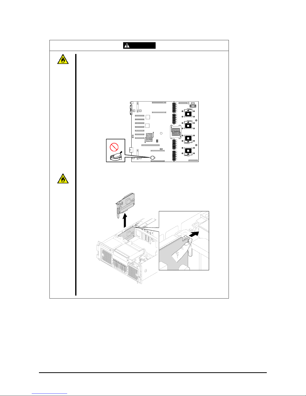
WARNING
Do not remove the lithium and NiMH batteries.
Your server contains lithium and NiMH batteries. Do not remove the battery.
There is a danger of explosion if the battery is incorrectly replaced. Placing the
lithium or NiMH battery close to a fire or in the water may cause an explosion.
When the server does not operate appropriately due to the failure of lithium and
NiMH batteries, contact your service representative to replace only with the
same or equivalent type recommended by the manufacturer. Do not
disassemble the server to replace or recharge the battery by yourself.
Base board
The onboard or optional RAID Controller (Disk Array Controller) also contains a
Ni-MH battery.
To dispose of the Ni-MH battery, remove the RAID Controller (Disk Array
Controller), and then remove the battery from the board.
For the battery location of the optional RAID Controller (Disk Array Controller),
refer to the manual coming with the RAID Controller (Disk Array Controller).
Lithium battery
Page 28

1-14
USER SUPPORT
When the server requires after-sales service, check if the warranty is still valid, and determine which service is
necessary as indicated on the "Certificate".
Before Asking for Repair , do the following when the server appears to fail:
1. Check if the power cord and the cables to other devices are properly connected.
2. See Chapter 8 to find if your problem fits one of the descriptions. If it does, take the recommended measure to
try and correct the issue.
3. Check if the software required for the operation of the server is properly installed.
4. Check the server using a computer virus detection program. Computer virus detection programs are available
for purchase in stores.
If the server still appears to fail after you have checked the above points, consult with your service representative. Take
notes on LED indications of the server and alarm indications on the display unit before calling, these may provide a
significant help to your service representative.
When your server will be repaired
Prepare the following when having your server repaired:
Certificate
Notes of the messages displayed on the display unit
Error information*
Records of the server and peripheral equipments
* Error information in cludes the Error Message shown in Chapter 8.
Prepare the error information only when required by your service representative.
Page 29
1-15
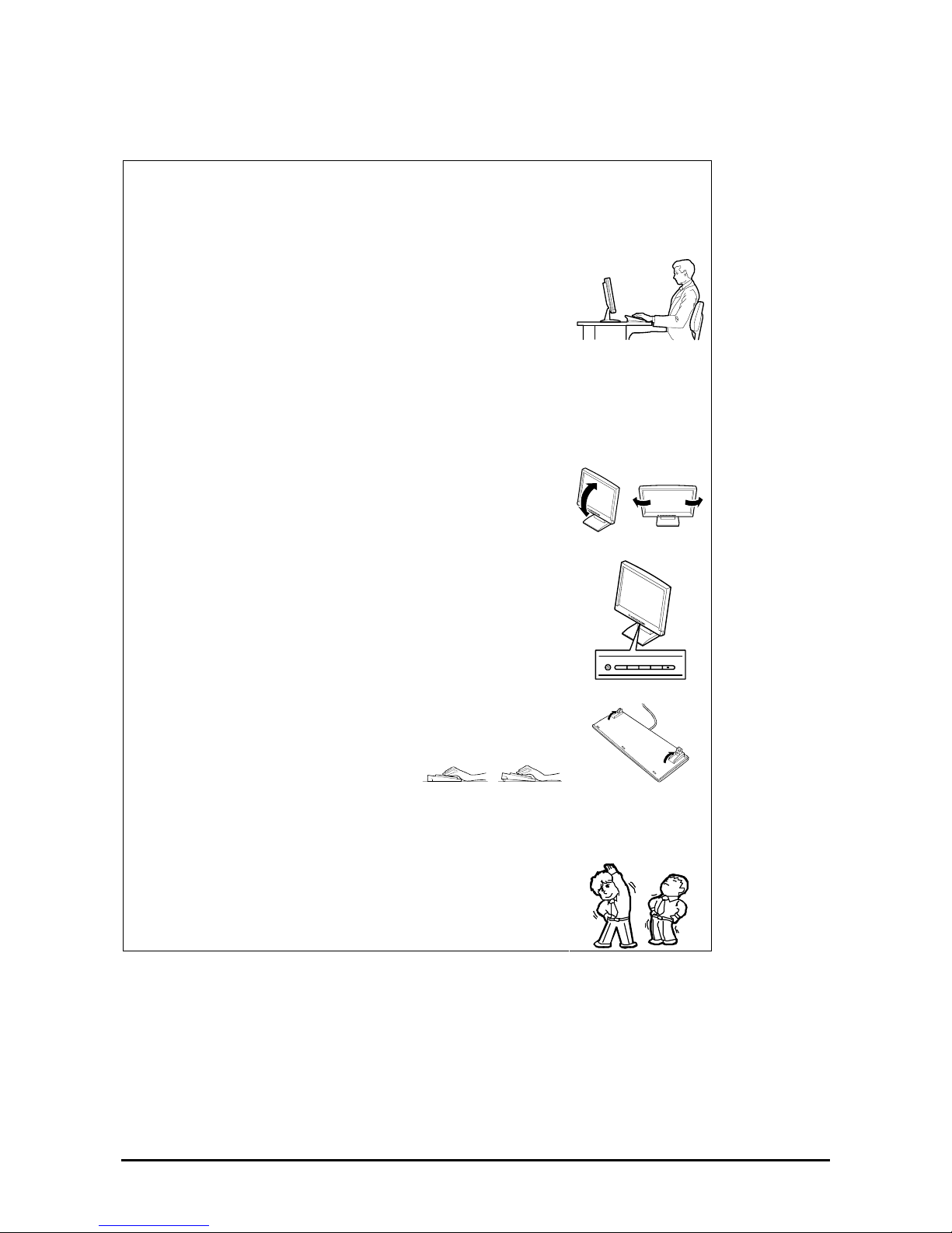
Advice for Health
The longer you keep using the computer equipment, the more you
become tired, which may cause disorders of your body. When you use a
computer, observe the following to keep yourself from getting tired:
Good Working Posture
Your working posture is good if the following are satisfied when you use a
computer:
• You sit on a chair with your back straight.
• Your hands are parallel with the floor when you put them on the
keyboard.
• You look at the screen slightly lower than your eye height.
No part of your body must be under excessive strain, your muscles must
be relaxed.
Your posture is bad when you sit with your back hunched up or you
operate a display unit with your face close to the screen. A bad working
posture may cause eye strain or poor eyesight.
Adjustment of the Display Unit Angles
Most display units are designed for adjustment of the horizontal and
vertical angles. This adjustment is important to prevent the screen from
reflecting bright lights and to make the display contents easy to see. You
will not be able to keep a "good working posture" and you will feel more
tired than you should if you operate a display unit without adjusting
horizontal and vertical angles.
Adjustment of Screen Brightness and Contrast
The display unit has brightness and contrast adjustment functions. The
most suitable brightness and contrast adjustment depends on the
individual and on the working environment (well-lighted room or
insufficient light). Adjust brightness and contrast so that the screen is easy
to see. An extremely bright or dark screen will have cause eye troubles.
Adjustment of the Keyboard Angle
The keyboard provided with the server is designed for adjustment to a
certain angle. Adjust the keyboard at an angle at which the keyboard is
easy to operate. The adjustment assists in reducing strain on your
shoulders, arms, and fingers.
Cleaning the Equipment
Clean the equipment regularly. It is difficult to see the display contents on
a dusty screen. Keeping your equipment clean is also important for your
sight.
Fatigue and Rest
If you feel tired, you should stop working and do light exercises.
Page 30

2-1
Chapter 2
General Description
This chapter provides information that you should be familiar with before using the server. It includes names and
functions of the components and features of the server.
Page 31

2-2
OVERVIEW
Your server is a highly reliable, high-powered, fault-tolerant, high-capacity, multiprocessing server based on the
Quad-Core Intel® Xeon® Processor 7300 series or Dual-Core Intel® Xeon® Processor 7200 series. It is a solid
performer and offers the latest technology. The combination of computng performance, memory capacity, and integrated
I/O provides a high performance environment for many server market applications. These range from large corporations
supporting remote offices, to small companies looking to obtain basic connectivity capability such as file and print
services, e-mail, web access, web site server, etc.
Your server is housed and available as a rack-mount system. Your server conveniently installs into a standard EIA
19-inch rack cabinet.
Your server includes a CD-RW/DVD-ROM drive, a 2.5-inch hard disk drive bay, and removable media device bay
(Option). The 2.5-inch hard disk drive bay can contain up to eight hard disk drives.
As application requirements increase, you can expand your server with an additional processor, additional memory,
add-in boards and peripheral devices: tape devices, DVD-ROM, and hard di sk drives .
Page 32

2-3
Top View
1 Top cover
Open the top cover to install or remove optional memory boards, DIMMs, PCI boards, and
fans.
1
Page 33

2-4
Front View
1 Key hole
Insert the security key to lock/unlock the front bezel
2 Front bezel
Open the front bezel to access the POWER/SLEEP switch, 5.25-inch device (option), or
CD-RW/DVD-ROM drive, or to install or remove the USB floppy disk drive, hard disk drive,
processor, memory board, DIMM, PCI board, and fan.
1
2
LEDs
(See Chapter 8 for details.)
Page 34

2-5
Front View (with Front Bezel Removed)
Refer to Chapter 8 for more information on the LEDs indications.
1 CD-RW/DVD-ROM drive
The CD-RW/DVD-ROM drive reads data from the inserted CD/DVD-ROM.
1-1: Access LED (lights orange during the access)
1-2: CD/DVD tray eject button
1-3: Emergency hole
2 5-inch device bay
Install a 5-inch device into this slot.
3 Monitor connector (only for maintenance use)
Do not connect any display unit. This connector is exclusively used for maintenance.
4 DUMP switch
Press this switch to collect a memory dump if the memory dump feature is enabled on the
operating system (see Chapter 8).
5 Front USB1 (top) / Front USB2 (middle) / Front USB3 (bottom) connectors
Connect a device supporting the USB 2.0 (Hi-speed) interface.
6 Front fan box
7 2.5-inch device bay
Install a 2.5-inch hard disk drive. The last digit represents the slot number.
8 DISK Access LED
9 DISK Error LED
1 1-1 1-2 1-3 2 3 4 5
8 9
6 6 7-0 7-1 7-2 7-3 7-4 7-5 7-6 7-7
Page 35

2-6
Front View (Switches and LEDs)
Refer to Chapter 8 for more information on the LEDs indications.
1 RESET switch
Press this switch to reset the server.
2 DISK Access LED
3 LAN1/2 access LED
4 LAN3/4 access LED
5 STATUS LED
6 POWER/SLEEP LED
7 UID (Unit ID) LED
8 UID (Unit ID) switch
Use this switch to turn on or off the ID LED located on the front and rear panels of the server.
Pressing this switch once turns on the UID LED, and pressing it again turns it off.
9 POWER/SLEEP switch
Use this switch to power on/off the server.
If you press the switch once, the POWER/SLEEP LED goes on and the power is turned on.
If you press the switch again, the power is turned off.
The system is forcibly shut down when the power switch is pressed continuously for four
seconds or longer.
When the sleep feature is enabled:
¾ pressing this switch once places the server in sleep (power saving) mode,
¾ and pressing this switch again resumes the normal state (supported in Windows
Server 2003).
1
2
3 4 5 6 7
8
9
Page 36

2-7
Rear View
Refer to Chapter 8 for more information on the LEDs indications.
1 PCI Express slot (#1 to #7 from left)
Slots 1 and 2: Hot-plug PCI Express (x8)
Slots 3 and 4: Non-hot-plug PCI Express (x8)
Slots 5, 6, and 7: Non-hot-plug PCI Express (x4) (Can contain x8 board.)
2 Keyboard connector
Connects to the optional keyboard.
3 Mouse connector
Connects to the optional mouse.
4 Management LAN port
Upper LED: LINK/ACT LED Lower LED: 100/10 LED
5 LAN connector
Connects to a network system on LAN. The last digit represents the port number.
Enabling [Shared BMC LAN] in BIOS SETUP allows port 3 to be used for management LAN
as well as the standard LAN. However, the network performance may be reduced because
the data of both LANs must be transmitted or received (see Chapter 4).
6 1000/100/10 LED
7 UID (Unit ID) LED
8 UID (Unit ID) switch
9 AC inlet
Used to connect with the power cord of the server. To use 200 to 240 VAC power, the setting
must be changed.
10 LINK/ACT LED
11 Pow er supply unit LED
12 Power supply unit
The power supply unit supplies DC power to the server. The last digit represents the slot
number.
13 Serial port B connector
The serial port B connector is connected to a device with a serial interface.
The server cannot directly be connected to a leased line through the connector.
14 Monitor connector
Connects to the display unit.
15 Rear USB1 (top), Rear USB2 (bottom) co nnectors
Connects to the devices accepting the USB 2.0 interface (Hi-speed).
1
2 3 4 5-4 5-3
5-1
5-2
6
7
8
9
10
11-1 11-2 11-3
12-2
9
11-1 11-2 11-3
12-1
13
14
15
Page 37

2-8
Internal View
1 5-inch device bay
2 Memory board
3 Rear fan bay
4 Non-hot-plug PCI slot
5 Hot-plug PCI slot
1
2
3
4 5 3
2
Page 38

2-9
Base Board
1 Rear fan connector
The last digit represents the port number.
2 Memory board connector
The last digit represents the port number.
3 Front panel connector
4 Power BP interface connector
5 Power connector
6 Processor socket
The last digit represents the port number.
7 SAS riser connector
8 SATA connector
9 Internal USB connector
10 Lithium battery
11 Conn ectors for external devices
12 I/O riser connector
13 Jumper switch for clearing password
14 Jumper switch for clearing CMOS
15 Internal serial port A
16 PCI Express board slot (PCI #1 to #7 from top)
16-1: PCI #1 and #2 (Hot-plug PCI Express x8)
16-2: PCI #3 and #4 (Non-hot-plug PCI Express x8)
16-3: PCI #5, #6, and #7 (Non-hot-plug PCI Express x4)
1-2 1-1 2-B 2-A
3
5
6-1
6-2
6-3
6-4
11
16-1
16-2
16-3
14
13
12
11
1-4 1-3 2-C 10 2-D 9 8
4
7
15
Page 39

2-10
Memory Board
1 DIMM slot (The last digit represents the slot number.)
I/O Riser Board
1 Mouse connector
2 Keyboard connector
3 Management LAN connector
4 L AN connector #4
5 L AN connector #3
6 Baseboard interface connector
1-8
1-7
1-6
1-5
1-4
1-3
1-2
1-1
1
2
3
4
5
6
Page 40

2-11
SAS Riser Board
1 SAS port A
2 SAS port B
3 DIMM connector for RAID
4 RAID activation key
5 Ni-MH battery for RAID
FRONT
REAR
1
4
3
5
2
Page 41

2-12
STANDARD FEATURES
High performance Expandability
Intel® Xeon® Processor 7300/7200
series
– E7210 (Clock speed: 2.40GHz,
Secondary cache: 2x4MB)
– X7350 (Clock speed: 2.93GHz,
Secondary cache: 2x4MB
High-speed memory access
(Supports DDRII 667 FB DIMM
-compliant interleaved memory)
High-speed 1000BASE-T/
100BASE-TX/10BASE-T interface
(4 ports)
(1000Mbps/100Mbps/10Mbps
supported)
Wide variety of optional I/O slots
4 PCI Express (x8) slots
(2 slots support hot-plug)
3 PCI Express (x4) slot
(x8 board can be installed)
Large memory of up to 128 GB
2.5-inch hard disk drive bay holding 8 hard
disk drives
Remote power-on feature
Up to four multi-processors are available for
upgrade.
USB 2.0 interface
Backup device bay
Many Available Features
El Torito Bootable CD-ROM (no emulation
mode) format support
POWER switch mask
Software power-off
Remote power-on feature
AC-LINK feature
Intelligent Platform Management Interface
(IPMI) feature
Baseboard Management Controller (BMC)
Remote console feature
High-reliability Self-diagnosis
Power On Self-Test (POST)
Test and Diagnosis (T&D)
Maintenance Features
Off-line Maintenance Utility
Memory dump feature using the DUMP
switch
Power Saving Feature
Sleep feature (available for Windows Server
2003)
Easy and Fine Setup
EXPRESSBUILDER (system setup utility)
Express Setup
SETUP (BIOS setup utility)
RAID Configuration Utility
Management Utilities
Memory mirroring feature
Online sparing memory feature
Memory monitoring feature (error
correction/error detection)
Memory chipkill feature supported
Memory/processor degradation
feature
(logical isolation of a failed device)
Bus parity error detection
Thermal sensor
Error notification
Internal cooling fan monitoring
feature
Internal voltage monitoring feature
BIOS password feature
Security feature (security lock)
Redundant power supply (for 200 to
240 VAC power or partially for 100 to
120 VAC)
RAID system (Onboard RAID
Controller)
NEC ESMPRO
NEC DianaScope
Remote Management Feature
Page 42

2-13
Power Supplies
The server can continue its operation without interruption even if a single power supply unit fails (power redundant
configuration).
In addition, if the AC power of each power supply unit is divided into two lines, the server can continue its operation
without power interruption even if one of the AC power line fails (AC power redundant configuration).
If the power cord is disconnected from the power supply unit immediately after it is connected, the event "power
degraded" may not be registered in the OS event log, and only the event "power recovered" is registered.
Redundant Power Configuration
Your server is configured with the 100 VAC non-redundant power supply system at the factory.
To use your server with the redundant power system (100 VAC or 200 VAC), update the Platform Information Area
(PIA) and Sensor Data Record (SDR) in the server firmware.
Contact your supplier to obtain the latest firmware.
Peripheral Bays
The server is equipped with one slot to install a backup device such as a magnetic tape drive.
Available Devices
The 5-inch device slot can contain a single-height SCSI device.
Setting the SCSI ID
When connecting the 5-inch device with the optional SCSI controller, refer to the manual that comes with the
SCSI controller.
– Setting the terminator
Set the terminator to "OFF".
Page 43

2-14
Memory Mirroring Feature
Memory Mirroring Feature
The memory mirroring feature sets a memory board as spare memory in standby state. If the current memory board
encounters an uncorrectable error, the memory mirroring feature switches to the standby memory board. When this
feature is used, the current memory board and the standby memory board should be combined. Available combinations
are:
Mirroring with a pair of memory boards A and B and a pair of memory boards C and D
To enable the memory mirroring feature, the combined memory boards must have DIMMs of same size and capacities.
Setting the BIOS
Start SETUP and select [Advanced] → [Memory Configuration] → [Memory RAS Feature] perform the following
settings:
To enable the memory mirroring feature: Select [Mirror].
Others
Memory capacity displayed on the OS = total capacity of physically installed memory – capacity for standby
memory
Memory mirroring feature: 1/2 of actually installed memory capacity
Enabling the memory mirroring feature does not influence the applications operations.
The mirroring feature is automatically disabled when an error message is displayed:
The following indicates that the memory mirroring feature is in use:
a) The failing DIMM group is degraded when the server restarts.
b) If the NEC ESMPRO Agent has been installed, the following log is registered as a system log of Event
Viewer:
Source name: ESMCommonService
Event ID: 2313
Explanation: Part of the DIMM was isolated due to a memory error.
Memory number: XX
Date/time: XX
c) If a report setting is specified through the NEC ESMPRO Agent, a Manager reporting and ALIVE
reporting are performed. The report contents are as follows:
Explanation: Part of the DIMM was isolated due to a memory error.
Memory number: XX
Date/time: XX
Page 44

2-15
System Cooling
The chassis top cover must be installed for proper system cooling. Cooling components must be hot-swapped within
two minutes. This time period applies only to the time that the cooling component is physically removed, not from the
time of failure.
The cooling subsystem consists of hot-swap, redundant (7+1) fans. In a redundant configuration, the system supports
one fault at a time, either one fan fault or one power supply fault, and it supports the hot swapping of one component at
a time. If a cooling component fails, the system cooling is maintained and the system continues to operate while the
component is hot swapped.
System Board Features
The following subsections describe the system board major components.
Processor
The processor board accommodates one to four Intel® Xeon® Pr ocessor 7300/7200 series in the FC-PGA2 package.
DIMM Memory
To install or remove the DIMM, remove the memory board first. One memory board is factory-installed in the server.
Up to four memory boards (128GB maximum) can be installed in the server.
Install the DIMM (Dual Inline Memory Module) to the DIMM socket on the memory board in the server. DIMMs are
installed in the ascending order of the DIMM socket number s in the unit of t wo m od ule s.
Onboard Video
The baseboard incorporates a Pilot II graphics accelerator with 16MB of video SDRAM. The onboard video can be
disabled through the BIOS Setup or when a video card is installed in any of the PCI Express slots.
Page 45

2-16
LSI MegaRAID™ SAS PCI EXPRESS™ ROMB
The SAS riser card includes the LSI MegaRAID™ SAS PCI EXPRESS™ ROMB (called "On Board RAID
(MegaRAID ROMB)" hereafter) The On Board RAID (MegaRAID ROMB) supports the following features:
Dual-channel SAS interface (CH0 and CH1)
Connect the HDD cage to CH0 and CH1.
RAID levels 0, 1, 5, 6, 10, and 50
512MB of cache memory
Battery-backup cache memory (option)
Network Interface Controllers
NOTE:
To ensure EMC product regulation compliance, the system must be used with
shielded LAN cables.
The base board includes Intel 82563EB Physical Layer Transceiver (PHY), and the I/O riser card includes the Intel
82575EB Network Interface Controller (NIC). Both chips support the following features:
Two channels of 10Base-T, 100Base-TX, and 1000BASE-T networks.
The both chips provide the standard IEEE 802.3 Ethernet Interface for 1000Base-T, 100Base-TX, and
10Base-T (802.3, 802.3u, 802.3ab).
Page 46

2-17
Remote Management
The server may be monitored and managed via LAN/WAN by using EXPRESSSCOPE Engine 2 and the NEC
DianaScope utility stored in the EXPRESSBUILDER DVD.
The EXPRESSSCOPE Engine 2 uses the BMC (Baseboard Management Controller) as a system management LSI.
The EXPRESSSCOPE Engine 2 provides the following features:
Monitoring of the power supply un it
Monitoring of the temperature, voltage, fans, and electric power status
Generation of SEL (system event log) at occurrence of a hardware failure
Monitoring of the system management watchdog timer
Monitoring of the periodic SMI timer
Remote management using a Web browser (e.g., resetting the server, power on/off, viewing System Event Log
(SEL))
Remote KVM and remote device features (A separately priced remote management license is required.)
Remote management via LAN/WAN by using NEC DianaScope and centralized management of several
systems
For more information about the remote management using the Web browser, remote KVM feature, and remote device
feature, refer to the "EXPRESSSCOPE Engine 2 User's Guide" stored in the EXPRESSBUILDER DVD.
NOTE: The measured value of temperature, voltage, fan, or electric power may contain an
error depending on the operating environment.
Degradation Feature
The degradation feature automatically isolates a failed DIMM, processor, or cooling fan to assure continuous operation
of the server when it is detected by the POST (Power On Self-Test, self-diagnosis program after power on).
Failed DIMMs, processors, and cooling fan may be identified on the screen that the POST displays, or with the BIOS
setup utility, "SETUP." They may also be identified on a system on which NEC ESMPRO installed.
Remote Power-On Feature (Wake On LAN/PME)
The remote power-on function powers on the server through a network. It sends a special packet from the management
computer to power on a remote server that is powered off.
To enable this feature, you must select "Enabled" for "Wake On LAN/PME" in the Advanced Chipset Control of the
Advanced menu of the BIOS setup utility, "SETUP." (See Chapter 4.)
The remote power-on feature is not available in the following cases. Press the POWER/SLEEP switch once to start the
OS, and turn off the server using an appropriate procedure.
Abnormal previous system shut-down
No power supply to the server (d ue to turned-off breaker, disconnected power cord, power blackout, etc.)
NOTE: Wake On LAN feature is supported in 100BASE-TX/1000BASE-T adapter on the
base board and I/O riser board.
AC-LINK Feature
When the power cord of the server is connected to an uninterruptible power supply (UPS) unit, the server supports the
Page 47

2-18
power linkage feature that enables control over the power supply from the UPS to the server. AC-LINK feature can be
enabled or disabled with "AC-LINK" in the Server menu of the BIOS setup utility, "SETUP." (See Chapter 4.)
Security
T o help prevent unauthorized entry or use of the system, the system includes a full lockable front panel and a Server
Management software that monitors the system intrusion switches.
Security with Mechanical Locks and Monitoring
The front bezel of the server features a mechanical lock to prevent access to the front of the computer chassis.
The computer chassis includes an intrusion switch for the top cover. When this cover is opened, the switch transmits an
alarm signal to the system board, where server management software processes the signal.
Software Locks via the System Setup Utility
The BIOS SETUP Utility provides a number of security features to prevent unauthorized or accidental access to the
system. Once the security measures are enabled, access to the system is allowed only after the user enters the correct
password(s). For example:
Enable the keyboard lockout timer so that the server requires a password to reactivate the keyboard and
mouse after a specified time-out period – 1 to 120 minutes.
Set and enable an administrative password.
Set and enable a user password
Set a secure mode to prevent keyboard or mo use input and to prevent use of the front panel reset, power and
sleep switches.
Activate a hot-key combination to enter the secure mode quickly.
Disable writing to the floppy disk drive when the secure mode is set.
Page 48

2-19
EXPRESSBUILDER
The EXPRESSBUILDER helps you install the Operating System, the Management software or use the maintenance
utilities.
Refer to Chapter 6 for details.
The functions of the EXPRESSBUILDER are:
To install the Operating System.
"Express Setup" helps you install the Windows. (See Chapter 5.)
To diagnose the system.
EXPRESSBUILDER includes the test and diagnostics to check your server. (See Chapter 6.)
To create the drivers disks*.
Use this function to create the OEM-Disk which is used at the Windows manual installation. (See Chapter 6.)
To update the BIOS.
Use this function to update the system BIOS or firmware of the server. (See Chapter 6.)
To update the Windows System*.
"Update the system" in the Autorun Menu updates several Windows resources. (See Chapter 6.)
To install the applications*.
You can install several Windows applications from the Autorun Menu. (See Chapter 6.)
To read the documents*
You can access the documents from the Autorun Menu. (See Chapter 6.)
* These functions are available under Windows system.
Page 49

2-20
NEC ESMPRO
NEC ESMPRO is a server management software that runs on the OS. NEC ESMPRO includes the NEC ESMPRO
Manager for the server monitoring terminal and the NEC ESMPRO Agent for the server.
NOTE: For more information on the major functions of NEC ESMPRO, system
configuration and setups done with NEC ESMPRO, see Chapter 6.
Available functions depend on the OS you install. Ask your service representative for
details.
Maintenance Tools
The Maintenance Tools is used for maintenance and fault analysis of the server. This tool is usually used by the service
representative.
See Chapter 7 for details.
System Diagnostic Utility
The system diagnostic utility contained in the EXPRESSBUILDER is useful to detect the hardware failures. See
Chapter 7 for details.
NEC DianaScope
The NEC DianaScope is a software for the remote management of the server.
The NEC DianaScope can control the managed server even if the OS is not running on the managed server.
See Chapter 6 and online document in the EXPRESSBUILDER.
Page 50

2-21
USING YOUR SERVER
This section describes basic operations of your server, including how to use devices such as the CD-RW/DVD-ROM
drive. See Appendix B for notes on using DVD/CD-ROM, and accessories including the keyboard and the mouse.
Front Bezel
Remove the front bezel to power on/off the server, to access the CD-RW/DVD-ROM drive, and to install/remove hard
disk drives to/from the 2.5-inch hard disk drive bay.
IMPORTANT: To open the front bezel, you must unlock the door with the provided
security key.
Installing or Removing the Front Bezel
You must remove the front bezel when powering on/off the server, accessing the CD-RW/DVD-ROM drive,
installing/removing a hard disk drive to/from the 2.5-inch hard disk drive bay, or removing the top cover.
1. Insert the attached security key into the key slot, press slightly on the key and turn it one quarter to the left to
release the lock.
2. Hold the right end of the front bezel lightly and pull it toward you.
3. Slide the front bezel to the left a little to remove the tab from the frame and then rem ove the front bezel from
the server.
2
1
To install the front bezel, latch the tab at the left side of the front bezel on the server frame. After the
installation, lock the front bezel by using the key for security.
Frame
Tabs
Unlock Lock
Page 51

2-22
POWER/SLEEP Switch
Use the POWER/SLEEP switch to turn on/off the server.
Power On
Press the POWER/SLEEP switch on the front of the computer chassis.
The POWER/SLEEP LED lights in green.
IMPORTANT:
If the power cord is connected to a power control device such as a UPS (Uninterruptive
Power Supply), make sure that the power control device is powered.
If the power cord is connected to the server, an initial diagnosis of the hardware starts.
The POWER/SLEEP switch does not work during this diagnosis. Wait for about 30
seconds, and press the POWER/SLEEP switch.
Do not power off the server until the characters following the full-screen logo appear on
the screen. Depending on your configuration, it may take three to five minutes.
Sleep
The POWER/SLEEP switch allows you to save almost all power of the server (power-saving mode or sleep mode).
NOTE: To use the SLEEP switch, an OS supporting the sleep feature is required.
(Available in W indows Server 2003)
Provide the settings for power saving on the operating system, then press the POWER/SLEEP switch on the front of the
server to place the server in the power-saving mode. (The POWER/SLEEP LED blinks.) In the power-saving mode, the
server retains the memory data and the status of the previous operations.
To resume the original state, press the POWER/SLEEP switch. (It may take a little time to resume the original state.)
NOTE: The operational level in the power-saving mode depends on the OS in use.
(Available in W indows Server 2003.)
IMPORTANT: Do not change the system configuration while in a power-saving mode,
you might fail to resume the original state.
POWER/SLEEP LED
POWER/SLEEP switch
POWER/SLEEP LED
POWER/SLEEP switch
Page 52

2-23
POST
The POST (Power On Self-Test) is the self-diagnosis feature saved in the base board of the server.
When the power of the server is turned on, the POST automatically runs to check the base board, I/O riser board,
memory board, processor, keyboard, and mouse. During the POST, messages indicating that several BIOS setup utilities
are started may also appear.
At the shipment of the server, it is set to have a full screen logo appear on the display unit during POST. Pressing Esc
allows the information to be displayed during the POST execution.
NOTE: The POST results can be automatically displayed (without pressing the Esc key).
To achieve this, open the BIOS Setup Menu, and change the "Boot-time Diagnosis Screen"
setting from "Advanced" to "Enabled".
It may not always be necessary to check the POST results. Check the POST messages in the following cases:
Installation of the server
Suspicion of failure
Abnormal number of beeps in the period between power-on and OS start
Error message on the display unit
POST Flow
The flow of the operations executed by POST is sequentially described below:
IMPORTANT: Depending on the system configuration, the message "Press Any Key"
may appear on the display screen for an installed optional board. Refer to the option manual
and press any key.
1. After power-on, the POST is activated to start the memory check. The message indicating the counted size of
the base memory and that of the additional memory appears at the upper left corner of the display screen. In
addition, the following message appears at the bottom of the screen.
Press <F2> to enter SETUP or <F12> Network
NOTE: If you change the factory-default for [Extended RAM Step] in [Advanced] menu
of BIOS SETUP and execute the memory test, pressing Space skips the m em ory test.
It may take several minutes to complete the memory check depending on the size of the memory installed in
the server. Similarly, it may take about a minute to display the proper information on the screen at rebooting.
2. If optional boards, such as a RAID Controller are installed, the POST displays a message prompting the start
of the BIOS setup utility for the optional board.
Refer to the manual that comes with the option board for more information.
When you press Ctrl and any other key at the same time to start the setup utility of the optional board, a
subsequent key entry may sometime fails (e.g., key entry is not accepted or incorrectly recognized). In this
case, press Ctrl again to recover.
3. The POST displays the SCSI ID numbers used by the connected SCSI devices on the screen.
4. The POST detects the Onboard RAID Controller and displays the message prompting the start of the
WebBIOS (if no keyboard key is pressed, the POST automatically continues). If necessary, press the keys
according to the screen display.
Page 53

2-24
LSI MegaRAID SAS-MFI BIOS Version XXXX (Build MMM DD, YYYY)
Copyright (c) 2007 LSI Logic Corporation
HA -X (Bus X Dev X) MegaRAID SAS PCI Express(TM) ROMB
FW package: X.X.X-XXXX
X Logical Drive(s) found on the host adapter.
X Logical Drive(s) handled by BIOS
Press <Ctrl> <H> for WebBIOS
Now press Ctrl + H. The utility starts upon the POST completion.
NOTES:
Using WebBIOS allows you to build or change the RAID configuration with internal
SAS hard disk drives.
To build or change RAID configuration with SAS hard disk drives connected to the
LSILogic MegaRAID SAS 8480E Disk Array Controller, use the Universal RAID
Utility. WebBIOS does not support this feature.
The Onboard RAID Controller (MegaRAID ROMB) has a factory-installed battery. See
Chapter 8 for error messages related to the battery. See also "Battery for Onboard RAID
Controller (MegaRAID ROMB)" in Chapter 4.
5. Displays the message notifying you of the detection of the processor and of the connected keyboard and
mouse.
6. Displays any of the following messages.
Pattern 1:
Press <F2> to enter SETUP or <F12> to Network
Pattern 2:
Press <F1> to resume, <F2> to enter Setup, <F12> to Network
* The displayed message varies depending on the device status.
Page 54

2-25
NOTE: The operation or utility to be started at each key entry is described below. These
operations or utilities may not always be started.
F2
Press F2 to start the BIOS setup utility. Start the utility to change the settings of the
server in order to fit the environment in which the server is used. In general, the setting
require no changes, except when an error message is displayed. See Chapter 4 for more
information.
F12
Press F12 to run the network boot.
F1
If message "Press <F1> to resume" appears, an error has been detected during POST.
See "Error messages during POST" for the information on the messages and the proper
actions to take to solve the errors. If an error message appears, pressing F1 allows the
BIOS setup utility to be started.
7. When a password is set in the BIOS setup utility SETUP, the screen prompting you to enter the password
appears after the normal termination of POST.
The password can be entered for up to three times. After three wrong entries, the server cannot be started. In
this case, power off the server, wait for about 10 seconds, and then power on the server again.
IMPORTANT: Set the password only after the OS installation.
8. The OS starts at the end of the POST.
POST Error Messages
When the POST detects an error, it displays an error message on the display unit screen. See Chapter 8 for POST error
codes.
IMPORTANT: Note the messages displayed before consulting with your service
representative. Alarm messages are useful information for maintenance.
Power Off
Follow the procedure below to power off the server. If the power cord of the server is connected to a UPS, refer to the
manual that comes with the UPS or the manual for the application that controls the UPS.
IMPORTANT: Always allow the POST to complete before powering off the server.
1. Shut down the OS.
2. Press the POWER/SLEEP switch on the front of the server.
The POWER/SLEEP LED goes off.
3. Power off the peripheral devices.
Page 55

2-26
Floppy Disk Drive
Your server is not equipped with a floppy disk drive. Use the optional USB floppy disk drive if necessary.
CD-RW/DVD-ROM Drive
Your server is equipped with a CD-RW/DVD-ROM drive on its front to read data from a CD/DVD-ROM. The
CD/DVD-ROM provides larger and faster data read than the floppy disk.
CAUTION
Observe the following instructions to use the server safely. Failure to follow
these instructions may cause a fire, personal injury, or property damage. See
pages 1-3 to 1-8 for details.
Do not leave the tray ejected from the CD-RW/DVD-ROM drive.
Setting/Removing the CD/DVD-ROM
1.
Confirm that the server is powered on (and the POWER/SLEEP LED lit) before setting the CD/DVD-ROM
on the CD-RW/DVD-ROM drive.
2. Press the media tray eject button on the front of the CD-RW/DVD-ROM drive. The tray comes out. Put the
CD/DVD-ROM on the tray carefully and securely with the label facing upward.
CD/DVD tray eject button
Page 56

2-27
3. Press the CD/DVD tray eject button or push the front of the tray lightly to retract it into the drive.
IMPORTANT: If a noisy sound is emitted by the CD-RW/DVD-ROM drive after setting a
CD/DVD-ROM, and set it again correctly.
To take out the media from the CD-RW/DVD-ROM drive, press the CD/DVD tray eject button to eject the tray. (If the
access LED is lit orange, the CD/DVD-ROM is being accessed and the CD/DVD tray eject button is disabled.) Some
OS have a command to eject a tray.
After taking out the CD/DVD-ROM, retract the tray into the drive.
If you fail to eject the CD/DVD-ROM tray with the CD/DVD-ROM tray eject button, follow the procedure below.
1. Press the POWER/SLEEP switch to power off the server. (The POWER/SLEEP LED goes off.)
2. Insert a metal pin of approximately 1.2 mm in diameter and 100 mm in length (a straightened large paper clip
will make a substitute) into the emergency hole on the upper front of the CD-RW/DVD-ROM drive and
gently push it in until the tray is ejected.
Page 57

2-28
IMPORTANT:
Do not use a toothpick or a plastic stick that could break easily.
If the above procedure does not let you take out the CD/DVD-ROM, contact your
service representative.
3. Hold the tray and pull it out.
4. Take out the CD/DVD-ROM.
5. Push the tray back into position.
NOTE: Using the CD/DVD-ROM
Keep the following notes in mind to use the CD/DVD-ROM for the server:
For a disk which does not conform to the CD/DVD standard, the playback of such a
disk with the DVD drive is not guaranteed.
Do not drop the CD/DVD-ROM.
Do not place anything on the CD/DVD-ROM or bend the CD/DVD-ROM.
Do not attach any label onto the CD/DVD-ROM.
Do not touch the signal side (nothing is printed on this side) with your fingers.
Place the CD/DVD-ROM with its printed side upward and gently put it on the tray.
Do not scratch the CD/DVD-ROM or write anything directly on it with a pencil or
ball-point pen.
Do not leave the CD/DVD-ROM near foods and drinks, or in a place exposed to
cigarette smoke.
Do not leave the CD/DVD-ROM in a high-temperature place (e.g., place exposed to
direct sunlight or close to a heater).
When dust or fingerprints a re vi si bl e on the CD/ D VD -R O M , wi pe the CD/ D VD -R OM
from its centre to the edge using a dry soft cloth slowly and gently.
Use the CD/DVD cleaner to clean the CD/DVD-ROM. Do not use record spray/cleaner,
benzene, or thinner.
Keep the CD/DVD-ROM in a CD/DVD-ROM case when not using it.
If the CD/DVD-ROM emits a lot of noise in the CD-RW/DVD-ROM drive, remove the
CD/DVD-ROM and insert it back again.
Do not hit the CD/DVD-ROM with the screw fixing the top cover when setting or
removing the disc.
Page 58

3-1
Chapter 3
Setting Up Your Server
This chapter describes how to set up your server appropriately for your system, on a step-by-step basis.
Page 59

3-2
SETUP FLOW
Follow the flowchart below to set up the server.
Selecting a site
Select a suitable site for the server.
Unpacking the system
Unpack the server and accessories from the shipping carton box.
Assembling the rack-mount system
Assemble the 19-inch rack cabinet and install the server.
Connecting the peripheral devices
Connect the peripheral devices to the server.
Connecting the power cord
Connect the power cord to the server.
Turning on the server
Power on the server to start the software setups. Setups depend on the optional
internal devices installed and on the peripheral devices connected.
Installing the operating system
Install an operating system to the server. See Chapter 5.
Installing the utilities
Install the utilities provided on the EXPRESSBUILDER DVD.
See Chapter 6.
Making backup copies of the system information
Once all the system setup procedures are completed, make backup copies of the
system information.
System information is required for server recovery in case of trouble or after
replacing the system board.
Page 60

3-3
SELECTING A SITE
Your server unit should be mounted in a standard EIA 19-inch rack cabinet.
Refer to the documentation attached to the rack or contact your service representative for the installation of the rack.
WARNING
Observe the following instructions to use the server safely. Failure to follow
these instructions may result in death or serious personal injury. See pages 1-3
to 1-8 for details.
Do not use the server in any unapproved place.
CAUTION
Observe the following instructions to use the server safely. Failure to follow
these instructions may cause a fire, personal injury, or property damage. See
pages 1-3 to 1-8 for details.
Do not carry or install the server only by a single person.
Do not install the server in a place where the load is concentrated on a
specific point.
Do not install any components in the server only by a single person.
Do not pull out a device from the rack if the rack is unstable.
Do not provide wiring exceeding the rating power.
IMPORTANT: Increase in temperature within the rack and air flow
If several servers are installed in the rack or if the ventilation within the rack is not enough,
the temperature in the rack may be raised by the heat generated from the units, and be
higher than the operation temperature of the server (10 to 35°C).
This causes the server to operate improperly. Review the air flow within the rack or in the
room and take sufficient measures in order to prevent the temperature within the rack from
exceeding the warranted temperature range during the system operation.
Page 61

3-4
The following figure illustrates a site suitable for installing the rack cabinet.
Place having available
space of 1 m or more in
front, side and rear of the
server.
100 to 120 Vac/200 to 240 Vac
parallel bi-polar wall power
outlet with the ground line.
Wall outlet to connect the
supplied power cord.
Room that satisfies the
following conditions for
operation: *
Temperature: 10 to 35ºC
Humidity: 20 to 80% (no
condensation)
* We recommend that the server should be used in a room where
temperature is in the range between 15 to 25ºC.
1 m
1 m
1 m
1 m
Page 62

3-5
Do not install the rack in the places listed below. Not doing so may cause some malfunctions to occur.
Do not:
Locate the rack in a narrow space that would prevent devices from being pulled out from the rack completely.
Locate the rack on a floor that cannot bear the total weight of the rack and devices mounted in the rack.
Locate the rack in a place where stabilizers cannot be installed or where the rack can be installed only after
proper earthquake-resistant is constructed.
Locate the rack on an uneven or slanting floor
Locate the rack in an area with drastic temperature change (near a heater, air conditioner, or refrigerator).
Locate the rack where intense vibrations may be generated.
Locate the rack where corrosive gas may be generated (ex. vapor of sulphur), chemicals are nearby, or
chemicals may be sprayed accidentally.
Place the rack on a carpet that is not anti-static.
Locate the rack in a place where some objects may fall on the rack.
Locate the rack near a device that is generating intense magnetic fields (such as a TV, radio,
broadcast/communication antenna, power transmission wire, and electromagnetic crane.) If unavoidable,
contact your service representative to request proper shielding.)
Locate the rack where the power cord of the server must be connected to an AC outlet that shares other
devices with large power consumption.
Locate the rack next to an equipment that generates power noise (e.g., contact spark at power-on/power-off of
commercial power supply through a relay). If you must install the server close to such equipment, request
your service representative for separate power cabling or noise filter installation.
Locate the rack where the following conditions cannot be satisfied.
Operating conditions: *
Temperature: 10 to 35°C
Humidity: 20 to 80% (no condensation)
* We recommend using the server in a room where the ambient temperature ranges between 15 to 25°C.
* If installed in a closed or multi-unit rack assembly, the required air flow for cooling might not be maintained,
and this causes the operating ambient temperature of the rack environment to rise higher than the room
ambient temperature. Therefore, consideration should be given to installing the server in an environment
compatible with the rated ambient temperature (10 to 35°C) and appropriate air flow.
Page 63

3-6
Installing or Removing the Server into/from the Rack
This subsection provides the instructions necessary ton install the rack-mount server unit into a standard EIA 19-inch
rack cabinet.
This subsection also describes the removal procedure for the rack mount server unit from the 19-inch rack cabinet.
WARNING
Observe the following instructions to use the server safely. Failure to follow
these instructions may result in death or serious personal injury. See pages
1-3 to 1-8 for details.
Do not use any rack which does not conform to the relevant standard.
Disconnect the power cord(s) before installing or removing the server.
CAUTION
Observe the following instructions to use the server safely. Failure to follow
these instructions may cause a fire, personal injury, or property damage. See
pages 1-3 to 1-8 for details.
Do not pull out more than one device at a time from the rack.
Do not lift the server only by a single person.
Always install the server in the specified place.
Do not install the server without its cover in the rack.
Do not pinch your finger with mechanical components.
Page 64

3-7
Checking Components
Confirm that the following tools or components are provided before attempting the installation.
No. Item Q'ty Remarks
1 Front bezel 1
2 Slide rail assembly (L) 1 "L" is stamped on the rail.
3 Slide rail assembly (R) 1 "R" is stamped on the rail.
4 Cable arm 1
5 Arm stopper 1
6 Tie-wrap 10 25 cm long.
7 Screw (A) 4 Two are for spare.
8 Screw (B) 2
Required Tools
A #2 Phillips screwdriver and flat tip screwdriver are recommended for assembling the rack-mount system.
1
2
3
4
5
6
7
8
Page 65

3-8
Installation Procedure
Install the server on the rack as described in the following procedure.
1. Define the position (height) at which the server is to be installed.
The server is 4U high. The bottom of the rail aligns with the bottom of server.
2. Make sure that the black lever surely locks the components.
If not, lock them.
NOTE: There are four levers to secure the components. Lock all four levers securely.
Template (Front) Template (Rear)
Page 66

3-9
3. Define the position of the slide rail assembly so that the bottom of the rail bracket is located at the lower
position of the server.
IMPORTANT: If the slide rail is inclined during installation, inner fails may protrude.
NOTES:
Check the direction of the slide rail assembly.
– Make the bracket face the outside of the rack.
– The slide rail has different shapes in its left and right side. Refer to the stamp on the
rail (Front → L / Front → R).
The front and rear supports of the rack have rectangular holes for screw fastening. For
the NEC rack, round stamps are provided in 1U. As shown in the figure, a stamp must
be positioned at the tip of slide rail assembly (lower side).
The rail bracket is 3U high.
Make sure that the fingers are locked in the rectangular holes.
Stamp (located at the
lower right position of
slide rail assembly)
Make sure that the
fingers are locked in
the rectangular holes.
Page 67

3-10
4. Secure the left and right sides of the slide rail assembly (for the rear side of the rack), with two screws (A).
NOTES:
Make sure that the frame tips on the slide rail assembly are squarely aligned with the
rectangular hole frames of the rack and that the four screw holes of the rail can be seen
through the mating rectangular holes of the rack.
Check that the slide rail assembly is level.
5. Install the other slide rail assembly on the opposite side of the rack as described in steps 2 to 4 above.
NOTE: Make sure that the slide rail assembly is installed at the same level than the slide
rail assembly installed first.
Page 68

3-11
6. Hold the server by three or more persons to mount it on the rack.
CAUTION
Observe the following instructions to use the server safely. Failure to follow
these instructions may cause a fire, personal injury, or property damage. See
pages 1-3 to 1-8 for details.
Do not lift the server only by two or less persons.
Do not pinch your fingers with the mechanical components.
Do not use your fingers to push the release lever.
Pull the inner rail, and install it so that its cutout engages with the projection on the side of the server.
IMPORTANT: The center cutout has locking mechanism. Make sure that it is surely
locked.
During the first installation, you may feel strong friction when pushing because the mechanical components
cannot be completely engaged with each other. Force the way in.
Mating portion
Locking lever
Page 69

3-12
7. Install the cable arm to the inner rail (to the right side viewed from rear of the server).
NOTE: Install the cable arm so that its protrusions align with holes on the inner rail.
8. Install the other side of the cable arm to the outer rail.
Page 70

3-13
NOTE: When installing the server into an NEC rack, fix the arm stopper to the slide rail
assembly with screw (B).
9. Push the server into the rack once to check the installation position.
To push the server into the rack, lift the green release levers at both sides of the rail (using a screw driver) to
unlatch the server. Make sure your fingers do not get caught in the process.
IMPORTANT:
Push each release lever using a screwdriver or a similar tool. Pushing a release lever
with your fingers may cause serious injuries.
Two release levers are provided on each side of the rail. Release only the green levers.
10. Pull out or push the server into the rack several times to confirm that it slides smoothly.
11. Connect the power cord and interface cables.
NOTE: Before connecting the cables, be sure to read the precautions given in "Connecting
Peripheral Devices".
12. Secure the server to the rack using two thumb nuts.
Viewed from inside
Arm stopper
Push the arm stopper in the direction shown
by the arrow mark so that the folded portion
hits the end, then fix it with the screw.
Release lever
Page 71

3-14
13. Install the front bezel.
The installation is completed.
Screws
Page 72

3-15
Removal Procedure
Do not remove the server from the rack by yourself.
CAUTION
Observe the following instructions to use the server safely. Failure to follow
these instructions may result in death or serious personal injury. See pages
1-3 to 1-8 for details.
Do not lift the server only by two or less persons.
Do not pinch your finger with mechanical components.
Parts of the server may be hot.
Do not pull out a device from the rack if the rack is unstable.
Do not pull out more than one device at a time from the rack.
1. Make sure that the server is powered off, and remove the power cords and all interface cables from the server.
2. Release the security lock and remove the front bezel.
3. Remove the two screws (A) located on both sides of the front face of the server.
4. Hold the handle to pull out the server from the rack slowly and carefully. The latches click.
Frame
Tabs
Unlock Lock
Page 73

3-16
5. Push the left and right release levers to release the lock and then pull out the server from the rail slowly.
IMPORTANT:
Push each release lever using a screwdriver or a similar tool. Do not use your fingers,
which could get caught, causing severe injuries.
Pull out the server slowly with its bottom supported by more than one person.
See the "Installation procedure" to remove the rack-mount kit from the rack.
Release lever
Page 74
3-17
CONNECTING PERIPHERAL DEVICES
Connect peripheral devices to the server. The server is provided with connectors for wide variety of peripheral devices
on its front and rear. The figure on the next page illustrates the available peripheral devices for the server in the standard
configuration and the locations of the connectors for the devices.
CAUTION
Observe the following instructions to use the server safely. Failure to follow
these instructions may cause a fire, personal injury, or property damage. See
pages 1-3 to 1-8 for details.
Do not connect any interface cable with the power cord of the server plugged
to a power source.
Do not use any unauthorized interface cable.
IMPORTANT:
Power off the server and a peripheral device before connecting them. Connecting a
powered peripheral device to the powered server will cause malfunctions and failures
(not applicable to USB devices).
To connect a third-party peripheral device or interface cable to the server, consult with
your service representative for the compatibility of such a device or cable. Some
third-party devices must not be used with this server.
Plug in the keyboard and mouse with "Δ" on the connector upward.
A leased line cannot be connected directly to the serial port connectors.
Secure the power cord(s) and interface cables with a lock spring or the tie-wrap attached
to the power supply unit.
Form the power cord leaving some slight slack around the AC inlet of the server. This
prevents the cord from coming off when the server is pulled out.
Confirm that no pressure is applied to the power cord plug.
Be sure to use the cable for 200 VAC (optional), if you use the server with 200 VAC
power. The AC power cord provided with the server accepts 100 VAC only. Do not use
the cord with 200-VAC power.
Guide the cables in such a way that they will not come into contact with the door or the
guide rails on the sides of the server.
Page 75

3-18
Keyboard
Mouse
Hub (multiport repeater)
1000BASE-T /
100BASE-TX /
10BASE-T
Device with a USB
interface (USB2.0)
(e.g., keyboard)
Network system
on LAN
(connected via a
hub)
Device with a USB interface
(e.g., keyboard)
Hub
(multiport repeater)
100BASE-TX /
10BASE-T
Finally connect the provided power cord to the receptacle.
If connecting the server to a UPS, see the explanation below.
Device with a serial
interface (e.g., modem /
management PC)
Direct connection to a
leased line is prohibited.
Management PC
Display unit
FRONT
REAR
For 100 VAC power, use
the parallel bi-polar wall
power outlet with the
ground line.
For 200 VAC power, use
the AC power cord
dedicated to 200 VAC.
Page 76

3-19
CONNECTING THE POWER CORD
Connect the provided power cord to the server.
WARNING
Observe the following instructions to use the server safely. Failure to follow
these instructions may result in death or serious personal injury. See pages 1-3
to 1-8 for details.
Do not hold the power plug with a wet hand.
CAUTION
Observe the following instructions to use the server safely. Failure to follow
these instructions may cause a fire, personal injury, or property damage. See
pages 1-3 to 1-8 for details.
Do not plug the power cord into an improper power source.
Do not connect the power cord to an outlet on which other devices are
already connected.
Insert the power plug into the outlet as far as it goes.
Use the authorized power cord only.
1. Plug the provided power cord into the AC inlet on the rear of the server.
2. Plug the other end of the power cord into the wall outlet.
3. Secure the power cord with a tie wrap.
Tie wrap
Page 77

3-20
To connect the power cord from the server to an uninterruptible power supply (UPS), use the service outlets on the rear
of the UPS. Refer to the manual that comes with the UPS for more information.
When connecting the power cord from the server to a UPS, change the BIOS setup of the server to link with the UPS
power supply.
Change the "AC-LINK" parameter under the Server menu of the BIOS SETUP utility. See Chapter 4 for more
information.
Option slot
Reset button for
overload prevention
Outlet socket
Computer interface port
Voltage sensitivity setting button
Input connector
(NEMAL5-30P)
Connector for TVSS device
Input breaker
Page 78

3-21
TURNING ON THE SERVER
Turn on the server and follow the on-screen instructions.
IMPORTANT: Before turning on the server:
Some optional boards require additional setup with the SETUP utility before installation.
If the server has a PCI board with the PCI-to-PCI bridge installed, the SETUP utility
cannot be started. Check the board specifications to find out whether it requires
pre-installation setups before actually installing the board.
Some installed optional devices or connected peripheral devices require setups before
proceeding to the next step.
To use the server with no optional devices installed besides the graphic board, install the
desired OS to the server.
1. Make sure that the floppy disk drive contains no floppy disk and that the CD-RW/DVD-ROM drive contains
no bootable CD/DVD-ROM.
2. Press the POWER/SLEEP switch.
NOTES:
If the power cord is connected to a power control unit such as a UPS, turn on the power
control unit.
Connect the power cord and wait for about 30 seconds before pressing the
POWER/SLEEP switch to allow the BMC (Baseboard Management Controller)
firmware start-up.
POWER/SLEEP LED
POWER/SLEEP switch
Page 79

3-22
The POWER/SLEEP LED on the front of the server lights up.
After a few seconds, a full screen logo appears on the screen and the Power On Self-Test (POST) begins.
The POST runs automatically when you power on the server or reset it using a key combination (Ctrl + Alt +
Delete). The POST runs diagnostics, initializes the server, sets the interrupt vectors, detects any installed
peripheral devices, and boots the operating system (if installed). See Chapter 2 for a detailed description of
the POST.
If the server halts before completing the POST, the POST emits a beep code indicating a fatal system error
requiring immediate attention. (See Chapter 8, "Troubleshooting," for troubleshooting information.)
During the memory test, the POST displays the amount of memory it was able to access and test. Depending
on the amount of installed memory, it may take several minutes to complete the memory test.
NOTE: The factory-set is defined to hide the POST screen with a full-screen logo. You can
switch to the POST screen by pressing Esc. To change the start-up screen, use the BIOS
setup utility, "SETUP." (See Chapter 4 for details.)
During the POST, messages prompting you to launch the BIOS SETUP utility stored in ROM on system board or on an
installed option board will de displayed.
Start the BIOS SETUP utility corresponding to your system environment to change the BIOS setup.
¾ For more information on the BIOS SETUP of the server, see Chapter 4.
¾ For more information on the BIOS SETUP of the option board, refer to the manual that comes with the option
board.
Page 80

3-23
INSTALLING THE OPERATING SYSTEM
See Chapter 5 for more information on the Operating system installation.
IMPORTANT: Before installing the operating system, adjust the system date and time
using the BIOS setup utility "SETUP". See Chapter 4 detail.
INSTALLING THE UTILITIES
Install the utilities included with the server. See Chapter 6 for details.
MAKING BACKUP COPIES OF THE SYSTEM INFORMATION
The system information includes the current BIOS settings and any specific information for the server.
We recommend you save the information after completing the system setup. Note that without the backup data, you will
not be able to recover the information.
You can save the information as described in the following process.
1. Insert the EXPRESSBUILDER DVD into the CD-RW/DVD-ROM drive and reboot the system.
2. Select [Maintenance Tools (Normal mode)] .
3. Select [English].
4. Select [Maintenance Utility].
5. Select [System Information Management].
6. Insert a floppy disk into the floppy disk drive.
7. Select [Save].
Page 81

4-1
Chapter 4
Configuring Your Server
This chapter describes the Basic Input Output System (BIOS) configuration.
When you install the server for the first time or install/remove optional devices, thoroughly read this chapter for a better
understanding of the settings.
SYSTEM BIOS ~ SETUP ~
The SETUP utility is provided to make the basic hardware configuration for the server. This utility is pre-installed in the
flash memory of the server and ready to run.
The server is factory-configured with the correct parameters using the SETUP utility. Only use the SETUP utility in the
cases described below.
IMPORTANT:
The SETUP utility is intended for system administrator use only.
The SETUP utility allows you to set a password. The server is provided with two levels
of password: Supervisor and User. With the Supervisor password, you can view and
change all the system parameters of the SETUP utility. With the User password, system
parameters available for viewing and changing are limited.
Do not set any password before installing the OS.
The server contains the latest version of the SETUP utility. Dialog boxes appearing on
your SETUP utility, may thus differ from the descriptions in this manual. If you find
anything unclear, see the online help or ask your service representative.
Page 82

4-2
Starting the SETUP Utility
To run the SETUP utility, perform the following procedures:
1. Turn on the power of the server.
A full-screen logo appears on the screen (the POST screen may appear instead, depending on the
corresponding BIOS setting).
After a while, one of the following messages appears at the bottom of the screen.
Pattern 1:
Press <F2> to enter SETUP or <F12> to Network
Pattern 2:
Press <F1> to resume, <F2> to enter Setup, <F12> to Network
* The displayed message varies depending on the device status.
2. Press F2 to start the SETUP utility and display its Main menu.
If you have previously set a password with the SETUP utility, the password entry screen appears. Enter the
password.
Up to three password entries will be accepted. If you fail to enter the password correctly for three consecutive
times, the server halts. (You can no longer proceed.) Power off the server.
NOTE: The server is provided with two levels of password: Supervisor and User. With the
Supervisor password, you can view and change all system parameters. With the User
password, system parameters available for viewing and changing are limited.
Page 83

4-3
Description on On-Screen Items and Key Usage
Use the following keyboard keys to work with the SETUP utility. (Key functions are also listed at the bottom of the
screen.)
Cursor (↑, ↓):
Selects an item on the screen. The highlighted item is currently
selected.
Cursor (←, →):
Selects the Main, Advanced, Security, System Hardware, Boot, or
Exit menu.
– and +: Changes the value (parameter) of the selected item. When a
submenu option (an option preceded by "Æ") is selected, these
keys are disabled.
Enter Press Enter to select (determine) parameters.
Esc
Displays the previous screen.
F1:
Press F1 when you need help on SETUP operations. The help
screen for the SETUP operations appears. Press Esc to return to
the previous screen.
F9: Sets the parameter of the currently displayed item back to the
factory set parameter.
F10: Sets the parameter back to the one stored by the server before
the SETUP utility was started.
Indicates the current menu.
Indicates there
are submenus.
Setup item menu
Online help
window
Parameter (high-lights upon selection) menu
Explanation of key functions
Page 84

4-4
Configuration Examples
The following describes examples of the configuration requ i red to use software-link features or for system operations.
Link with Management Software
To link with the temperature monitoring feature of NEC ESMPRO Agent
Select [Server] - [Thermal Sensor] - [Enabled].
To control the power supply of the server with NEC ESMPRO Manager via the network
Select [Advanced] - [Advanced Chipset Control] - [Wake On Lan/PME] - [Enabled].
Select [Server] - [AC-LINK] - [StayOff].
NOTES:
[Wake On Lan/PME] feature is supported by the onboard LAN controller
(1000Base-T/100Base-Tx).
Immediately after AC power is turned on, the [Wake On Lan/PME] feature is enabled
regardless of the BIOS settings.
UPS
To link power supply with the UPS
To power on the server when the power is supplied by the UPS
Select [Server] - [AC-LINK] - [Power On].
To keep the server powered off even when the power is supplied from the UPS when the POWER switch is
used to power off
Select [Server] - [AC-LINK] - [Last State].
To keep the server powered off even when the power is supplied from the UPS
Select [Server] - [AC-LINK] - [StayOff].
Boot
To change the boot order of the devices connected to the server
Select [Boot] and specify the boot order.
To display the POST check results
Select [Advanced] - [Boot-time Diagnostic Screen] - [Enabled].
You can also press Esc while the full-screen logo is displayed to switch to the POST check results.
To control from the HW console
Select [Server] - [Console Redirection] and set each item.
Page 85

4-5
Memory
To enable the memory degradation feature
Select [Advanced] - [Memory/Processor Error] - [Halt].
To check the installed memory (DIMM board) status
Select [Advanced] - [Memory Configuration] and check the status indications.
The on-screen DIMM socket locations and on the memory board are associated as shown in the following
figure.
To clear the memory (DIMM board) error information
Select [Advanced] - [Memory Configuration] - [Memory Retest] - [Yes] and reboot.
To enable the memory mirroring feature
Select [Advanced] - [Memory Configuration] - [Memory RAS Feature], and select [Mirror].
DIMM #8
DIMM #7
DIMM #6
DIMM #5
DIMM #4
DIMM #3
DIMM #2
DIMM #1
Page 86

4-6
Processor
To enable the processor degradation feature
Select [Advanced] - [Memory/Processor Error] - [Halt].
To check the installed processor status
Select [Main] - [Processor Settings] and check the status indications.
The on-screen processor numbers and the socket locations on the base board are associated as shown in the
following figure.
To clear the processor error information
Select [Main] - [Processor Settings] - [Processor Retest] - [Yes] and reboot and reboot.
Processor #1
Processor #2
Processor #3
Processor #4
Page 87

4-7
Security
To set BIOS passwords
Select [Security] - [Set Supervisor Password] and enter a password.
The Supervisor password and User password can be set separately, and only the User password is restricted
when accessing the SETUP utility.
To enable/disable the POWER/SLEEP switch and SLEEP switch
Disabling
Select [Security] - [Power Switch Inhibit] - [Enabled].
Enabling
Select [Security] - [Power Switch Inhibit] - [Disabled].
IMPORTANT: Enabling [Power Switch Inhibit] disables the forced shutdown (see
Chapter 8) as well as the possibility to power on/off using the POWER switch.
External Devices
To set up external devices
Select [Advanced] - [Peripheral Configuration] and set up each device.
Internal Devices
To set up internal PCI devices
Select [Advanced] - [PCI Configuration] and set up each device.
To clear the hardware configuration data (after installing/removing internal devices)
Select [Advanced] - [Reset Configuration Data] - [Yes].
Page 88

4-8
PCI Hot Plug
To install the PCI board with the PCI hot plug
Select [Advanced] - [PCI Configuration] - [Hot Plug PCI Control] - [Minimum/Middle/Maximum*]
* The setting varies depending on the PCI board. See the tab le below.
Board name Setting Value
1000Base-T Adapter (2ch) Minimum
1000Base-T Adapter Minimum
Saving the Configuration Data
To save the BIOS configuration data
Select [Exit] - [Exit Saving Changes] or [Save Changes].
To discard changes to the BIOS configuration data
Select [Exit] - [Exit Discarding Changes] or [Discard Changes].
To resume the default BIOS configuration data (may differ from factory-set value)
Select [Exit] - [Load Setup Defaults].
To save the current value as user defaults
Select [Exit] - [Save Custom Defaults].
To load the user-defined defaults
Select [Exit] - [Load Custom Defaults].
Page 89

4-9
Menus and Parameters Descriptions
The SETUP utility includes the following six major menus:
Main
Advanced
Security
Server
Boot
Exit
To set minute functions, select a submenu from the above menus. The following describes the available functions and
parameters, as well as the factory-setting for each menu.
Main
After entering SETUP, the Main menu appears first. To display a submenu, position the cursor on a selection that
includes a submenu (preceded by symbol
Æ) and press Enter.
The items which can be set on the Main menu screen and their functions are described below.
Option Parameter Description Your Setting
System Time HH:MM:SS Sets the time.
System Date MM/DD/YYYY Sets the date.
SATA Port 1 –
Displays the information on the device
connected to the channel on the
submenu.
(Display only)
Language [English (US)]
French
German
Spanish
Italian
Select the language used for SETUP.
[ ]: Factory-set
Page 90

4-10
Processor Settings
Selecting "Processor Settings" on the Main menu shows the following submenu.
See the table below for the items.
Option Parameter Description Your Setting
Processor
Retest
[No]
Yes
Clears the error information on the processor.
Processor
Speed Setting
– Indicates the frequency of the processor.
Processor 1-4
CPUID
–
A numeral indicates the ID of processor.
"Disabled" indicates that the BMC has identified
the CPU as being defective.
"Not Installed" indicates that the processor is not
installed. (Display only)
Processor 1-4
L2 Cache
– Indicates the L2 cache of the processor.
Execute
Disable Bit
[Enabled]
Disabled
Disables or enables the Execute Disable Bit of
the processor.
Intel
SpeedStep(R)
Technology
Disabled
[Enabled]
Disables or enables the enhanced Speed Step
technology of Intel processor.
This menu appears only when the processor
supports this feature.
C1 Enhanced
Mode
Disabled
[Enabled]
Disables or enables the Enhanced Halt State
(C1E) feature of Intel processor.
This menu appears only when the processor
supports this feature.
Page 91

4-11
Option Parameter Description Your Setting
Virtualization
Technology
[Enabled]
Disabled
This menu appears only when the processor
supports Intel® Virtualization Technology.
Specify whether the Intel® Virtualization
Technology is enabled or disabled.
If the parameter is changed, the DC power of the
system must be turned off. Select [Exit] → [Exit
Saving Changes] and restart the system. Then,
turn off the DC power on the POST screen.
Hardware
Prefetcher
[Enabled]
Disabled
Disables or enables the Hardware Prefetcher of
the processor.
Adjacent Cache
Line Prefetch
[Disabled]
Enabled
Disables or enables the Adjacent Cache Line
Prefetch of the processor.
[ ]: Factory-set
Page 92

4-12
Advanced
The Advanced menu appears if you move the cursor to "Advanced."
To display a submenu, position the cursor on a selection that has a submenu (preceded by symbol Æ) and press Enter.
See the table below for the items.
Option Parameter Description Your Setting
Boot-time
Diagnostic
Screen
[Disabled]
Enabled
Specifies whether the self-diagnosis (POST)
running screen is displayed during boot.
If this item is set to "Disabled," a full-screen
logo appears during POST. (Pressing Esc at
that time displays the POST execution screen).
The Boot-time Diagnostic Screen is
automatically enabled if the Console
Redirection is enabled.
Reset
Configuration
Data
[No]
Yes
Select "Yes" to clear the extended system
configuration data area (system information
stored by POST). The parameter is
automatically changed to "No" after the system
has booted.
NumLock On
[Off]
Specifies whether the numlock is enabled or
disabled at boot.
Memory/
Processor Error
[Boot]
Halt
Indicates whether the POST stops at the
occurrence of a processor or memory error
during the execution of POST.
When a processor error or memory error is
encountered, the utility does not stop if this
item is set to "Halt", even when the "POST
Error Pause" of the "Server" menu is
"Enabled".
[ ]: Factory-set
Page 93

4-13
Memory Configuration
Selecting "Memory Configuration" on the Advanced menu displays the following screen.
See the table below for the items.
Option Parameter Description Your Setting
Installed
memory
– Indicates the mounted memory capacity
(Display only).
Available
under 4GB
– Indicates the capacity of memory available in
the area smaller than 4GB. (Display only)
Memory
Retest
[No]
Yes
Clears the DIMM group error status
information. Run this menu when the failed
DIMM(s) are replaced.
Extended
RAM Step
1MB
1KB
Every Location
[Disabled]
"1MB" indicates that the memory test is done in
the unit of 1MB. "1KB" indicates that the
memory test is done in the unit of 1KB.
"Every-Location" indicates that every memory
device is tested.
"Disabled" indicates that only the memory
initialization is done.
Online Spare
Memory
[Disabled]
Enabled
Active when the Online Spare Memory can be
configured with the installed DIMMs.
Select "Enabled" to enable the Online Spare
Memory feature.
Memory RAS
Feature
[Normal]
Mirror
Active when the Memory Mirroring can be
configured with the installed DIMMs.
Select "Mirror" to enable the memory mirroring
function.
[ ]: Factory-set
Page 94

4-14
Memory Riser Board x
Selecting "Memory Riser Board x (A to D)" on the Memory Configuration menu displays the following submenu.
See the table below for the items.
Option Parameter Description Your Setting
DIMM #1 - 8
Status
Normal
Not Installed
Disabled
Indicates the current memory status for each
memory board.
"Normal" indicates that the memory devices
operate normally.
"Not Installed" indicates that no memory
devices are installed. (Display only)
"Disabled" indicates that one or more memory
devices are defective.
For the DIMM socket associated with the
DIMM number on this menu, see page 4-5.
[ ]: Factory-set
Page 95

4-15
PCI Configuration
Selecting "PCI Configuration" on the Advanced menu displays the following screen. Selecting an item on the screen
allows the proper submenu to appear.
See the table below for the items.
Option Parameter Description Your Setting
PCI Slot 1-7
Option ROM
[Enabled]
Disabled
Disables/enables the Option ROM BIOS
on the PCI bus.
[ ]: Factory-set
IMPORTANT: If you want to boot the OS contained in the internal hard disk drive when
any of the PCI slots #1 through #7 contains a PCI card, the parameter for the "PCI Slot x
Option ROM" (x: slot containing the PCI card) must be set to "Disabled".
Page 96

4-16
Hot-plug PCI Control
Selecting "Hot-plug PCI Control" on the PCI Configuration submenu displays the following screen.
See the table below for the items.
Option Parameter Description Your Setting
Reserving
memory space for
PHP
[Disabled]
Minimum
Middle
Maximum
Determines memory space at every
empty slot for PHP (PCI Hot-plug).
Reserved memory space is:
[Disabled]
None
[Minimum]
6 (2+4) MB
[Middle]
48 (16+32) MB
[Maximum]
256 (192+64) MB
[ ]: Factory-set
NOTE: The bus number of the PCI slot varies depending on whether this parameter is set
to "Disabled" or to another setting. Pay attention when you need to setup the program
again.
Page 97

4-17
Onboard SAS/Onboard NIC/Onboard Video
Selecting "Onboard SAS", "Onboard NIC", or "Onboard Video" on the PCI Configuration submenu displays a screen
similar to the one shown below. (Shown below is the one when Onboard SAS is selected.)
See the table blow for the items.
Option Parameter Description Your Setting
Option ROM Scan
LAN #1-4 Option ROM
Scan
[Enabled]
Disabled
Specifies whether the expansion BIOS
of the onboard controller is enabled or
disabled.
[ ]: Factory-set
Page 98

4-18
Peripheral Configuration
Selecting "Peripheral Configuration" on the Advanced menu displays the following screen.
See the table below for the items.
IMPORTANT: Note that the interrupt and/or base I/O address cannot overlap with othe rs.
If the value set for the interrupt or base I/O address is used for another resource, the yellow
asterisk (*) appears. Properly reset any item displaying a yellow asterisk.
Page 99

4-19
Option Parameter Description Your Setting
Serial Port A Disabled
[Enabled]
Specifies whether the serial port A is
enabled or disabled.
Base I/O Address [3F8]
2F8
3E8
2E8
Interrupt IRQ 3
[IRQ 4]
Selects the base address and
interrupt (IRQ) for serial port A. These
menus are displayed only when the
Serial port A is enabled.
Serial Port B Disabled
[Enabled]
Specifies whether the serial port B is
enabled or disabled.
Base I/O Address 3F8
[2F8]
3E8
2E8
Interrupt [IRQ 3]
IRQ 4
Selects the base address and
interrupt (IRQ) for serial port B. These
menus are displayed only when the
Serial port B is enabled.
USB 2.0 Controller Disabled
[Enabled]
Specifies whether the USB 2.0
controller is enabled or disabled.
Legacy USB
Support
Disabled
[Enabled]
Specifies whether the USB keyboard
is available in an OS which does not
formally support USB.
Serial ATA Disabled
[Enabled]
Specifies whether the serial ATA is
enabled or disabled.
Native Mode
Operation
[Auto]
Serial ATA
Selects the Native Mode operation for
ATA.
NOTE:
Native Mode is not supported by all
the operating systems.
[ ]: Factory-set
Page 100

4-20
Advanced Chipset Control
Selecting "Advanced Chipset Control" on the Advanced menu displays the following screen. Positioning the cursor on a
menu (item preceded by symbol "
Æ") and pressing Enter displays the corresponding submenu.
See the table below for the items.
Option Parameter Description Your Setting
Multimedia Timer [Disabled]
Enabled
Selecting "Enabled" enables this
function if the OS supports the HPET
feature.
Intel(R) I/OAT [Enabled]
Disabled
Specifies whether the Intel(R) I/O
Acceleration Technology is enabled or
disabled.
Wake On
LAN/PME
[Enabled]
Disabled
Specifies whether the remote
power-on function through network is
enabled or disabled.
Wake On Ring [Disabled]
Enabled
Specifies whether the remote
power-on function through a serial
port is enabled or disabled.
Wake On RTC
Alarm
[Disabled]
Enabled
Specifies whether the remote
power-on function through an RTC
alarm is enabled or disabled.
[ ]: Factory-set
NOTE: When the 10GBase-SR adapter is installed, the server is powered on even if the
[Wake On LAN/PME] is set to [Disabled].
 Loading...