

Page 1

HIGH DEFINITION RECEIVER / RECORDER
Model : NHD-3000PVR
Page 2

HIGH DEFINITION RECEIVER / RECORDER
Model : NHD-3000PVR
USER’S MANUAL
Page 3
1
Warnings
01
Warnings
Read Instructions : All the safety and operating instructions should be read before the product is operated.
Retain Instructions : The safety and operating instructions should be retained for future reference.
Heed Warnings : All warnings on the product and in the operating instructions should be adhered to.
Follow Instructions : All operation and use instructions should be followed.
Cleaning : Unplug this product from the wall outlet before cleaning. Do not use liquid cleaners or aerosol
cleaner. Use a damp cloth for cleaning.
Attachment : Do not use attachments not recommended by the product manufacturer as they may cause
hazards.
The lightning flash with arrowhead symbol, within an equilateral triangle, is intended to
alert the user to the presence of uninsulated "dangerous voltage" within the product's
enclosure that may be of sufficient magnitude to constitute a risk of electric shock to
persons.
The exclamation point within an equilateral triangle is intended to alert the user to the
presence of important operating and maintenance (servicing) instructions in the literature
accompanying the appliance.
The appliance is not intended for use by young children / infirm persons without
supervision.
Young children should be supervised to ensure that they do not play with the appliance.
To prevent electric shock do not use this (polarized) plug with a receptacle or other outlet
unless the blades can be fully inserted to prevent blade exposure.
Change or modification not expressly approved by the party responsible for compliance
could void the factory warranty.
The apparatus shall not be exposed to dripping or splashing and that no objects filled
with liquids, such as vases, shall be placed on the apparatus.
The socket-outlet shall be installed near the equipment and shall be easily accessible.
WARNING : To prevent fire of shock hazard, do not expose this appliance to rain or moisture.
CAUTION :
1.
2.
3.
4.
5.
6.
Important Safeguard
Page 4

7.
8.
9.
10.
11.
12.
13.
14.
15.
16.
17.
18.
19.
Warnings
2
01
Warnings
Water and Moisture : Do not use the product near water - for example, near a bath tub, wash bowl, kitchen
sink, or laundry tub ; in a wet basement ; or near a swimming pool ; and the like.
Accessories : Do not place this product on an unstable table. The product may fall, causing serious injury
to a child or adult, and serious damage to the product. Use only with a table recommended by the
manufacturer, or sold with the product. Any mounting of the product should follow the manufacturer's
instructions, and should use a mounting accessory recommended by the manufacturer.
A product and cart combination should be moved with care. Quick stops, excessive force,
and uneven surface may cause the product and cart combination to overturn. Please refer
to picture on the right.
Ventilation-Slot and openings in the cabinet are provided for ventilation and to ensure reliable
operation of the product and to protect it from overheating, and these openings must not be blocked or
covered. The openings should never be blocked by placing the product on a bed, sofa, rug, or other similar
surface. This product should not be placed in a built-in installation such as a bookcase or rack unless
proper ventilation is provided or the manufacturer's instructions have been adhered to.
Power Sources : This product should be operated only from the type of power source indicated on the
marking label. If you are not sure of the type of power supply to your home, please contact NEC Service
Centre or NEC Pro Care Centre. For products intended to operate from battery power, or other sources,
refer to the operating instructions.
Polarization : This product may be equipped with a polarized alternating-current line plug. This plug will fit
into the power outlet only one way. This is a safety feature. Do not defeat the safety purpose of the
polarized plug.
Power-Cord Protection : Power-supply cords should be routed so that they are not likely to be walked on or
pinched by items placed upon or against them, paying particular attention to cords at plugs, convenience
receptacles, and the point where they exit from the product.
Lighting : For added protection for this product during a lighting storm, or when it is left unattended and
unused for long periods of time, unplug it from the wall outlet and disconnect the antenna or cable system.
This will prevent damage to the product due to lighting and power-line surges.
Power Lines : An outside antenna system should not be located in the vicinity or overhead power lines or
other electric light or power circuits, or where it can fall into such power lines or circuits. When installing an
outside antenna system, extreme care should be taken to keep from touching such power lines or circuits
as contact with them might be fatal.
Overloading : Do not overload wall outlets, extension cords, or integral convenience receptacles as this
can result in a risk of fire or electric shock.
Object and Liquid Entry : Never push objects of any kind into this product through opening as they may
touch dangerous voltage points or short-out parts that could result in a fire or electric shock. Never spill
liquid of any kind on the product.
Servicing : Do not attempt to service this product yourself as opening or removing covers may expose you
to dangerous voltage or other hazards. Refer all servicing to qualified service personnel.
Damage Requiring Service : Unplug this product from the wall outlet and refer servicing to qualified service
personnel under the following conditions :
a) When the power-supply cord or plug is damaged.
Page 5

3
20.
21.
22.
23.
Warnings
01
Warnings
b) If liquid has been spilled, or objects have fallen into the product.
c) If the product has been exposed to rain or water.
d) If the product does not operate normally by following the operating instructions. Adjust only those
controls that are covered by the operating instructions as an importer adjustment of other controls
may result in damage and will often require extensive work by a qualified technician to restore the
product to its normal operation.
e) If the product has been dropped or damaged in any way.
f
) When the product exhibits a distinct change in performance-this indicate a need for service.
Replacement Parts - When replacement parts are required, be sure the service technician has used
replacement parts specified by the manufacturer or have the same characteristics as the original part.
Unauthorized substitutions may result in fire, electric shock, or other hazards.
Safety Check : Upon completion of any service or repairs to this product, ask the service technician to
perform safety checks to determine that the product is in proper operating condition.
Heat : The product should be situated away from heat sources such as radiators, heat registers, stoves, or
other products (including amplifiers) that produce heat.
RF Interference : Do not operate a mobile phone in close proximity, as this may cause picture and sound
breakup and damage to main parts.
About the internal hard disk drive
Do not move the recorder while it is on.
Install and use the recorder on a stable, level surface.
Do not block the top cover vent holes.
Do not use the recorder where it is excessively hot or humid places, or where places are subject to
sudden changes in temperature. Sudden changes in temperature can cause condensation to form inside
the recorder. This can be a cause of HDD failure.
While the recorder is switched on, do not unplug from the wall socket or switch the electricity off from the
breaker switch.
Do not move the recorder immediately after switching it off. If you need to move the recorder, please
follow the steps below:
a) After the message ‘P-OFF’ (POWER OFF) is shown in the display, wait at least two(2) minutes.
b) Unplug from the wall socket.
c) Move the recorder.
If there’s a power failure while the recorder is on, there is a chance that some data on the HDD will be lost.
The HDD is very delicate. If used improperly or in an unsuitable environment, it is possible that the HDD
will fail after a few years of usage. Signs of problems include playback unexpectedly freezing and
noticeable block noise (mosaic) in the picture. However, sometimes there will be no warning signs of
HDD failure. If the HDD fails, no playback of recorded material will be possible. In this case, it will be
necessary to replace the HDD unit.
The internal hard disk drive (HDD) is a fragile piece of equipment. Please use the recorder following the
guidelines below to protect against possible HDD failure or to protect against accidental loss.
1.
2.
3.
4.
5.
6.
7.
8.
Page 6

4
Table of Contents
02
Table of Contents
01.
02.
03.
04.
05.
06.
07.
Warnings
Table of Contents
Supplied Accessories
Controls
Front Panel Controls and LEDs
Rear Panel Connectors
Battery Installation for Remote Control
Installation
Antenna Input
Connection to Digital TV (YPbPr)
Connection to Digital TV (RGB/HV)
Connection to RGB PC Monitor
Connection to Digital TV (HDMI/DVI)
Connection to HDMI/DVI PC Monitor
Connection to Analog TV (Composite/S-Video)
Connection to Digital Audio Amplifier
Basic Operation
Remote Control
On Screen Display
Channel Information
Channel Guide (EPG)
Channel Status
Channel List
Timeshift Control
Record Control (Dual Recording)
Timer Record List
Program List
Program List (Rename)
Playback Control
EDIT Control (Repeat, Cut, Split)
Closed Caption
1
4
6
7
8
10
11
12
13
14
15
16
17
18
19
22
23
24
25
26
27
28
29
30
31
32
33
Page 7

Table of Contents
08.
09.
10.
11.
12.
Teletext
PIP Control
Channel
Channel Edit
Channel Scan
Manual Scan
Channel Sorting
Channel Duplication
Parental Rating
Audio/Video
HDMI Video
HDMI Audio
Monitor Setup
Digital Audio Out
PIP Size
Vol. Control
PVR Manager
Program List
Skip Time
HDD Sleep Time
HDD Format
System
Opacity
Time Zone
Daylight Saving
Sleep Timer
New Password
Factory Default
About
Specifications
34
35
36
37
38
39
40
41
42
43
44
45
46
47
48
49
50
51
52
53
54
55
56
57
58
59
5
02
Table of Contents
※ Manufactured under license from Dolby Laboratories. Dolby and the double-D symbol are trademarks of Dolby
Laboratories.
Page 8
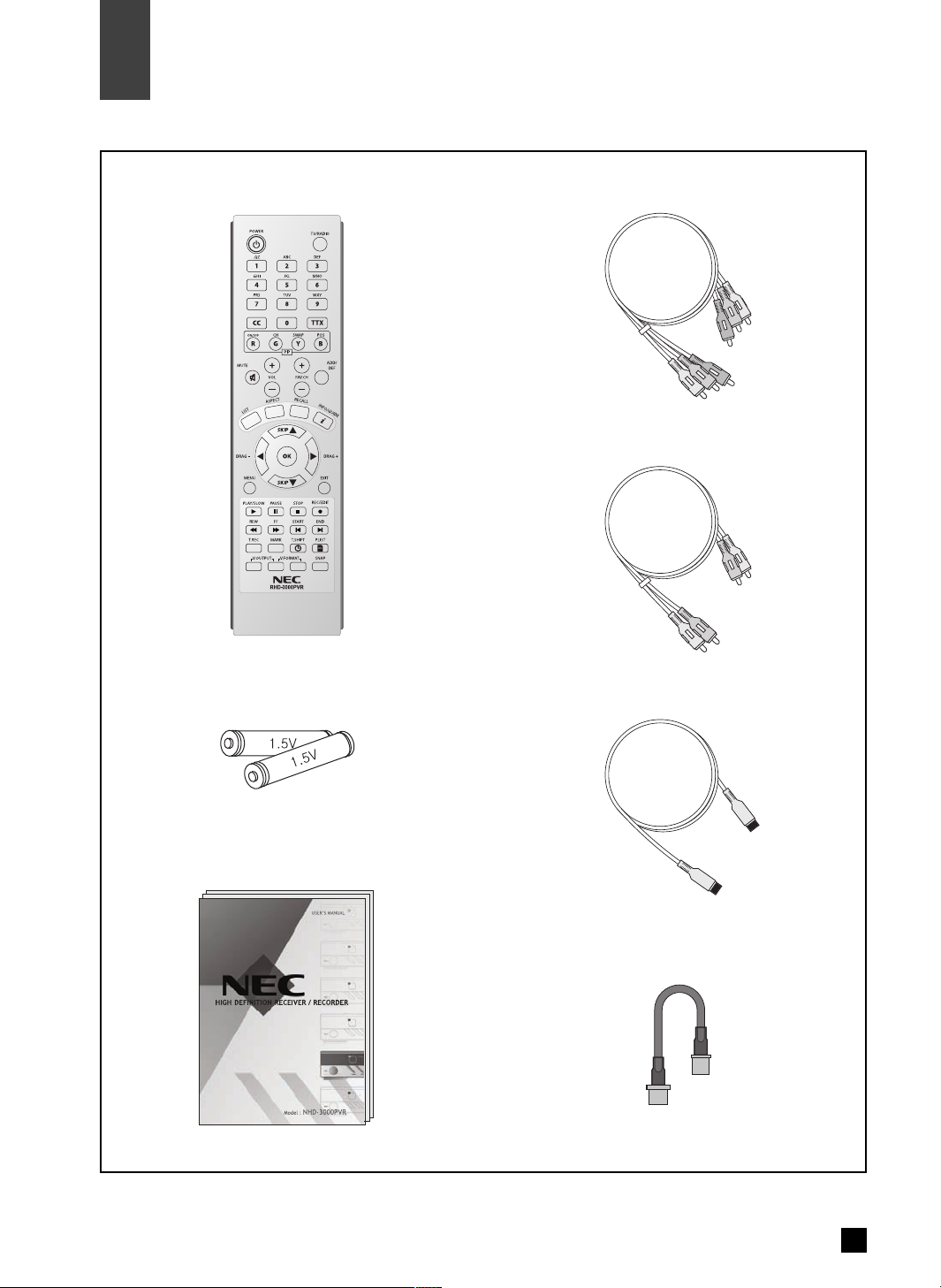
4. Component Video Cable
5. Audio Cable(L/R)
6.HDMI Cable
7. RF Loop Cable
1. Remote Control
2. Batteries
(size AAA)
3. User’s Guide
6
Supplied Accessories
03
Supplied Accessories
Make sure the following accessories are provided with product.
Page 9
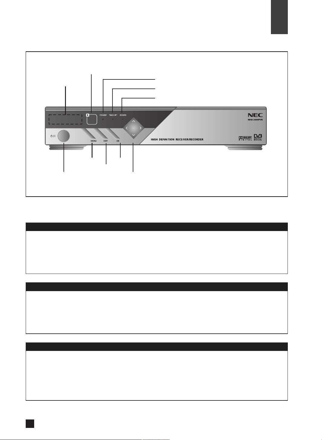
Power
Menu
Exit
OK
Arrow Buttons
Buttons
Front Display
Power On
Power Off
EXIT
Remote Control Sensor
POWER
Front Side
7
Front Panel Controls and LED’s
Controls
MENU
Front Display
04
LED Indicators
STANDBY
TIMESHIFT
RECORD
OK
Arrow Buttons
STANDBY Power & Remote Indicator LED
Timeshift Playback Indicator LED
Recording Indicator LED
Channel number is displayed.
C100 means digital channel number is 100.
A200 means radio channel number is 200.
Clock is displayed.
STANDBY Power & Remote Sensor Indicator LED.
During the period from STANDBY to ON condition, the STANDBY LED will be flashing.
Timeshift Playback Indicator LED.
Record Indicator LED.
Turns the unit on or off.
Display or exit the on screen menu.
Switch back to the previous menu screen that was displayed.
If the main menu is displayed, pressing the OK button will activate the highlighted MENU option.
Allows you to navigate on-screen menus and to adjust the system settings and preferences.
Page 10
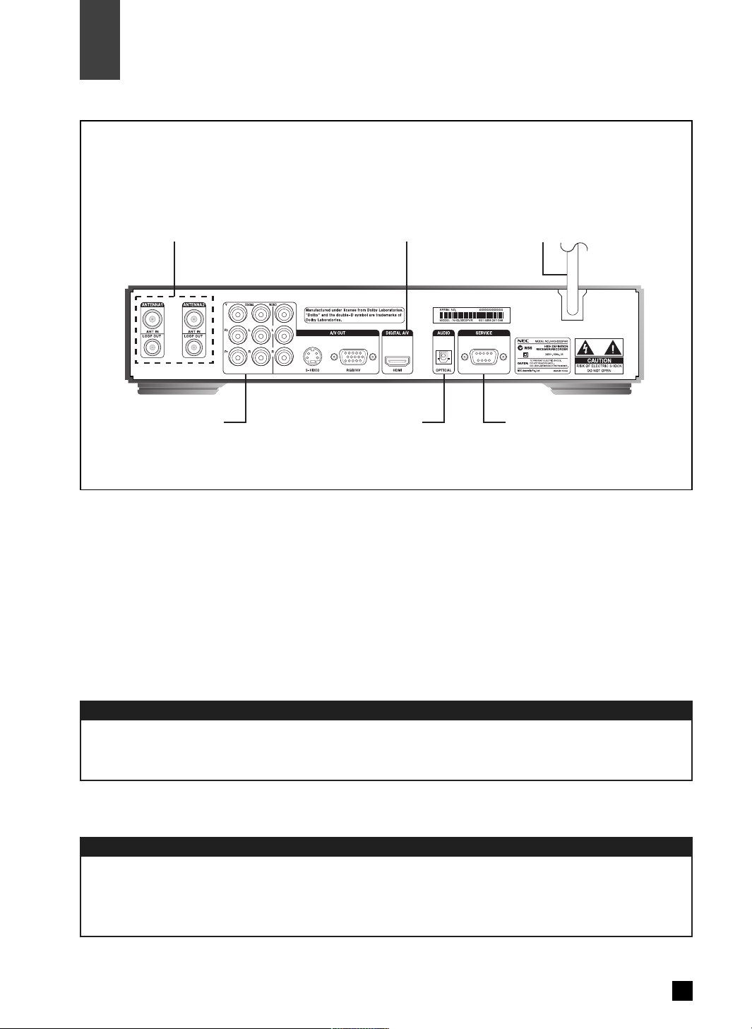
Antenna Input
Power Cord
8
Controls
◈ Note. Connection of input/output connector in rear panel should be done while power is OFF.
Rear Panel Connectors
04
Connect the cable from an off-air TV antenna to Antenna1 input.
Connect Antenna1 loop out to Antenna2 input with RF loop cable.
Rear Side
Service Port A/V Output
Antenna Input Power CordHDMI/DVI Output
Connect to the AC power (AC 240 ~ 250V / 50Hz).
Optical Audio Output
Page 11

Service Port
A/V Output
9
Rear Panel Connectors (Cont.)
04
Controls
The service port is for maintenance and software upgrade in the future.
The ‘A/V output’ consists of the followings :
Y, Pb, Pr : Component video output (576i, 576p, 720p, 1080i)
RGB/HV : RGB, PC monitor output (576p, 720p, 1080i)
HDMI/DVI : HDMI/DVI output (576p, 720p, 1080i)
Video or S-Video : Composite video or S-Video output (576i)
L, R : Analog audio output
COAXIAL : Digital audio output (Coaxial)
OPTICAL : Digital audio output (Optical)
Page 12
10
Controls
Battery Installation for Remote Control
04
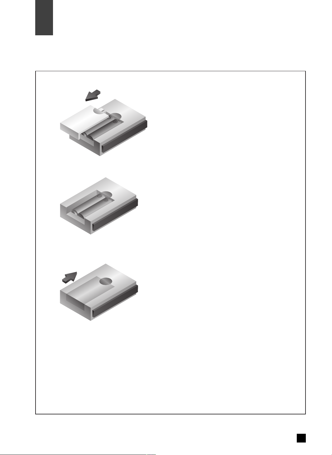
Remove the battery cover and install batteries like the diagram below.
1. Unlatch the battery compartment cover on the back
of remote control.
2. Insert 2 AAA batteries as shown, making sure
the + and - ends of each battery line up with
the corresponding marks in the battery
compartment.
3. Snap the cover back to the remote control.
Page 13
Connecting Antenna
11
Antenna Input
05
Installation
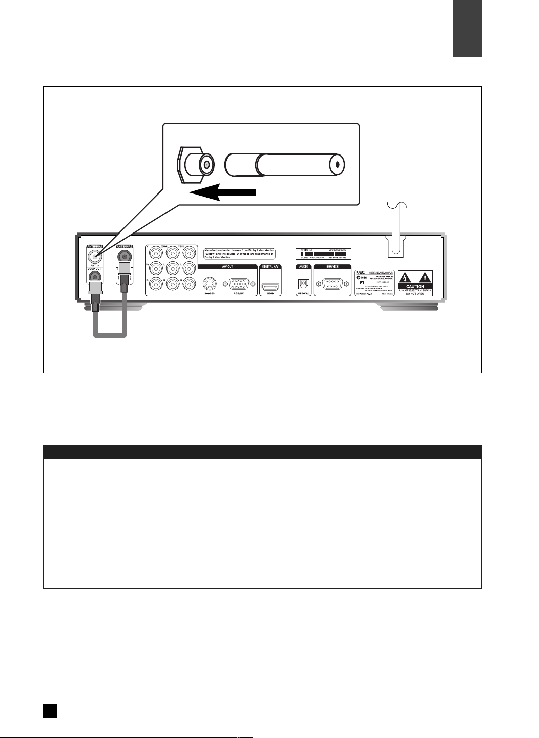
Connect the antenna or RF cable wire directly to ANTENNA1 IN and connect ANTENNA1 Loop
Out to ANTENNA2 Input by using RF loop cable.
◈ NOTE
· The STB(Set Top Box) should be unplugged before connecting antenna. (Power OFF mode)
· The RF OUT from the tuner will only work when the unit turns on. It will not give RF OUT during
STANDBY mode.
THE RF LOOP CABLE MUST BE CONNECTED, OTHERWISE THE UNIT WILL NOT
BE ABLE TO TUNE.
Page 14
Connect the Audio Cables
Connect the Video Cables
12
Installation
Connection to Digital TV (YPbPr)
05
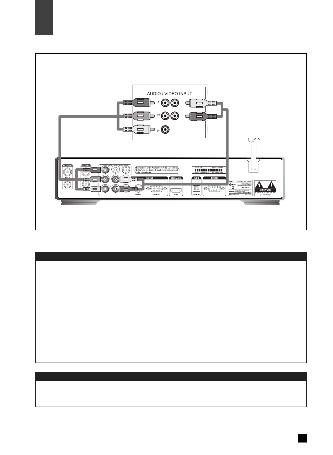
Connect an audio cable between the L/R Audio output jacks of the STB and the L/R Audio input jacks of
the digital TV or digital audio amplifier. (Refer to page 18)
Connect a video cable between the Component video output(Y : Green, Pb : Blue, Pr : Red) jacks of the
STB(Set Top Box) and the Component input jacks on the Digital TV according to corresponding colour.
On the Video Out Mode, select YPbPr as Video Output Type and select one of 1080i, 720p, 576p, 576i
as Video Output Resolution according to your digital TV.
◈ NOTE
· By pressing the remote, V-OUTPUT (2 buttons), you will be able to change the output ‘YPbPr’ and
‘RGB’. (YPbPr selection is usually used for Component Input, while RGB selection is usually used for
PC/HDMI Input)
· By pressing the remote, V-FORMAT (2 buttons), you will be able to change the format ‘1080i’,
‘720p’, ‘576p’, ‘576i’.
< Digital TV >
Page 15
Connect the Audio Cables
Connect the Video Cables
13
Connection to Digital TV (RGB/HV)
05
Installation
Connect an audio cable between the L/R Audio output jacks of the STB and the L/R PC Audio input
jacks of the digital TV or digital audio amplifier. (Refer to page 18)
Connect the RGB/HV output jack of the STB to the RGB input jack of the PC RGB input on the digital
TV. In regard to the Video Out Mode, select RGB as Video Output Type and select one of 1080i, 720p,
576p as Video Resolution according to your digital TV.
◈ NOTE
· By pressing the remote, V-OUTPUT (2 buttons), you will be able to change the output ‘YPbPr’ and
‘RGB’. (YPbPr selection is usually used for Component Input, while RGB selection is usually used for
PC/HDMI Input)
· By pressing the remote, V-FORMAT (2 buttons), you will be able to change the format ‘1080i’,
‘720p’, ‘576p’, ‘576i’.
< Digital TV >
Page 16
Connect the Audio Cables
Connect the Video Cables
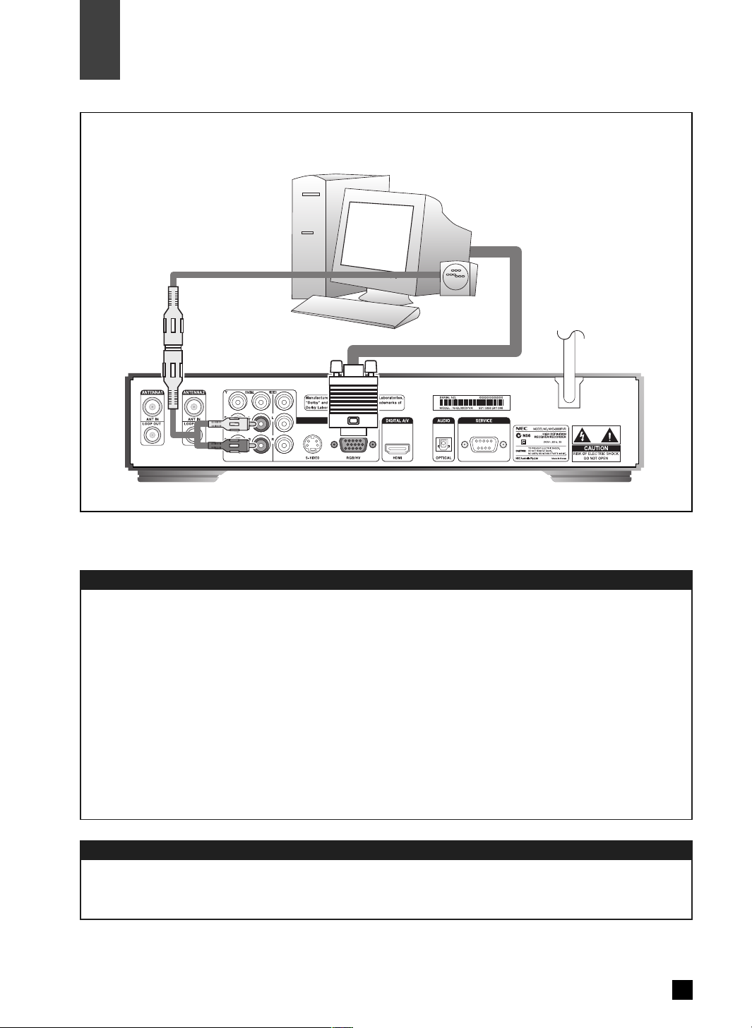
14
Installation
Connection to RGB PC Monitor
05
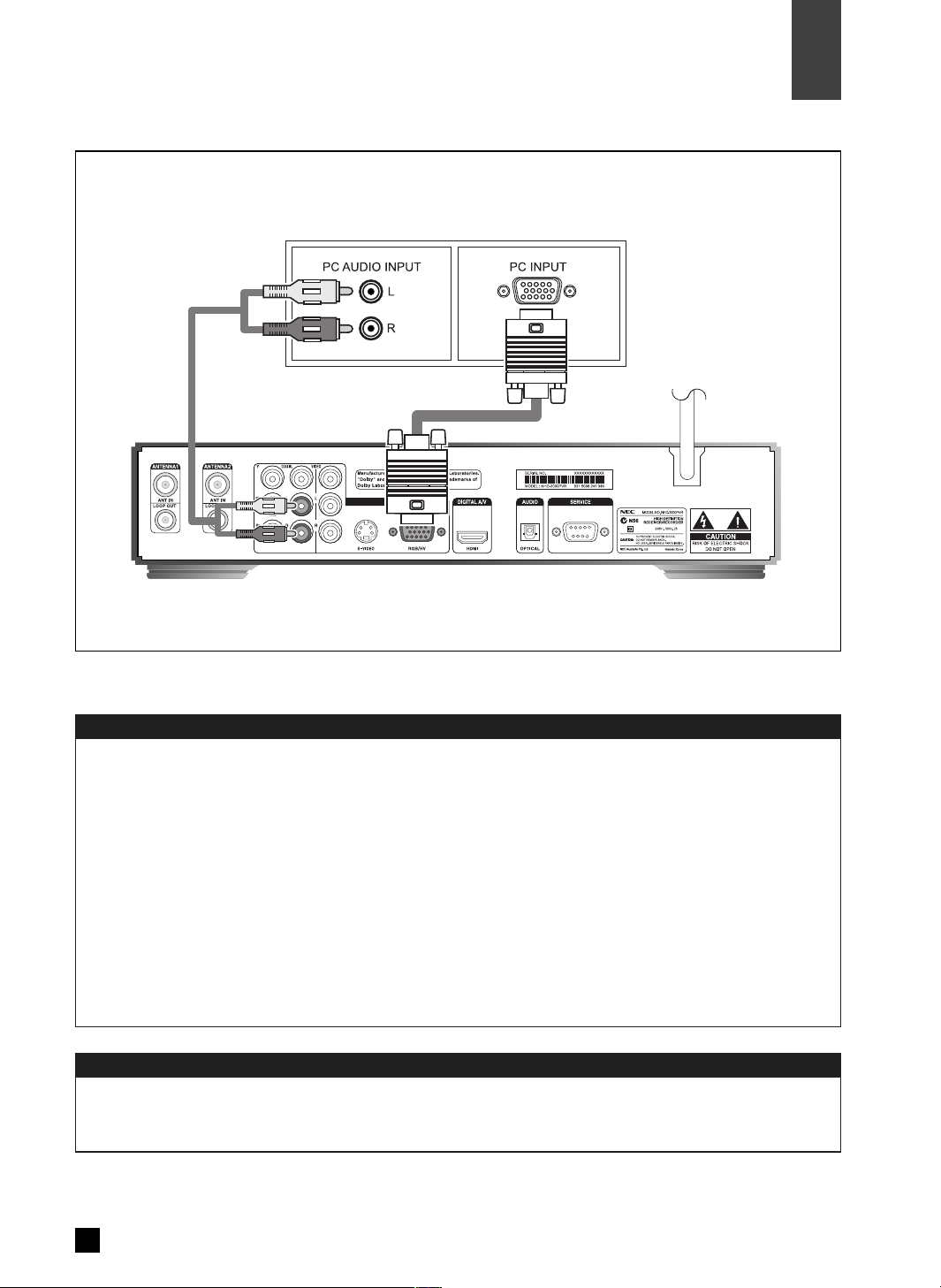
Connect an audio cable between the L/R Audio output jacks of the STB and the external speakers
that contain a sound amp. (Purchase separate jacks for PC speakers.)
Connect RGB/HV video output jack of the STB to the RGB jack of the PC monitor. In regard to the
Video Out Mode, select RGB as Video Output Type and select one of 1080i, 720p, 576p according
to Video Output Resolution of your PC monitor.
◈ NOTE
· By pressing the remote, V-OUTPUT (2 buttons), you will be able to change the output ‘YPbPr’ and
‘RGB’. (YPbPr selection is usually used for Component Input, while RGB selection is usually used for
PC/HDMI Input)
· By pressing the remote, V-FORMAT (2 buttons), you will be able to change the format ‘1080i’,
‘720p’, ‘576p’, ‘576i’.
Page 17
Connect the HDMI Cable
15
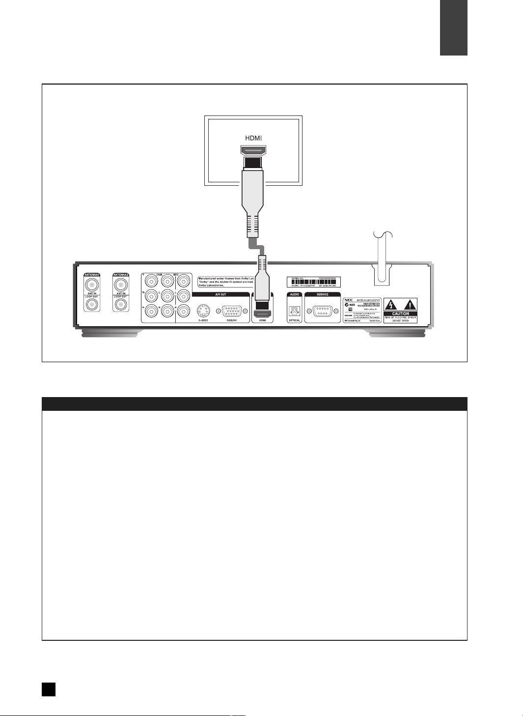
Connection to Digital TV (HDMI/DVI)
05
Installation
Connect the HDMI/DVI output jack of the STB to the HDMI input jack of the digital TV. In regard to the
Video Out Mode, select one of 1080i, 720p, 576p as Video Resolution according to your digital TV.
◈ NOTE
· By pressing the remote, V-OUTPUT (2 buttons), you will be able to change the output ‘YPbPr’ and
‘RGB’. (YPbPr selection is usually used for Component Input, while RGB selection is usually used for
PC/HDMI Input)
· By pressing the remote, V-FORMAT (2 buttons), you will be able to change the format ‘1080i’,
‘720p’, ‘576p’, ‘576i’.
· When you connect using HDMI, depending on your digital TV, you can change the value of video
timing by going to the HDMI VIDEO selection at the MENU. The two selections available are :
– HDMI means the value of video timing is setup for HDMI
– YPbPr/RGB means the value of video timing is setup for YPbPr/RGB
· You can view the difference between the two selections above by pressing ‘MARK’. If you see
OUTPUT, and there is a letter ‘H’ in the beginning (eg: OUTPUT: H1080), it means HDMI is selected.
If you see OUTPUT, (eg: OUTPUT: 1080), it means normal YPbPr/RGB is selected.
< Digital TV >
Page 18
Connect the Audio Cables
Connect the Video Cables
16
Installation
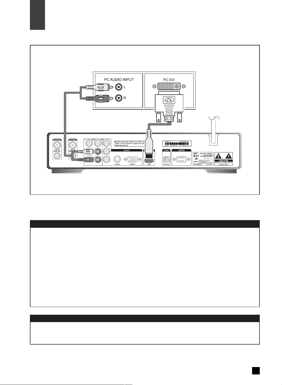
Connection to HDMI/DVI PC Monitor
05
Connect an audio cable between the L/R AUDIO output jacks of the STB and the external speakers
that contain a sound amp. (Purchase separate jacks for PC speakers.)
Connect HDMI/DVI jack of the STB to the HDMI/DVI jack of the PC monitor. In regard to the Video Out
Mode, select one of 1080i, 720p, 576p according to Video Output Resolution of your monitor. (Purchase
HDMI-to-DVI adapter.)
◈ NOTE
· By pressing the remote, V-OUTPUT (2 buttons), you will be able to change the output ‘YPbPr’ and
‘RGB’. (YPbPr selection is usually used for Component Input, while RGB selection is usually used for
PC/HDMI Input)
· By pressing the remote, V-FORMAT (2 buttons), you will be able to change the format ‘1080i’,
‘720p’, ‘576p’, ‘576i’.
Page 19
Connect the Audio Cables
Connect the Video Cables
17
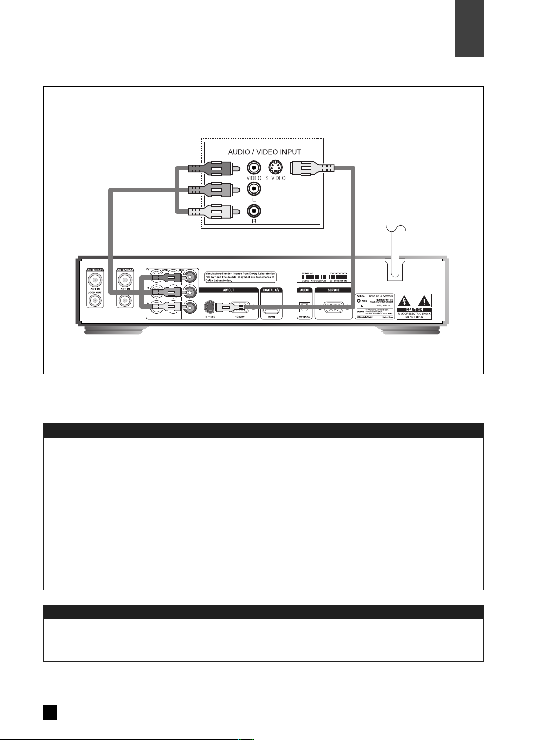
Connection to Analog TV (Composite/S-Video)
05
Installation
Connect an audio cable between the L/R Audio output jacks of the STB and the L/R Audio input jacks of
the analog TV.
Connect a composite cable between the Video output jack of the STB and the Video input jack of the
analog TV. Or, connect an S-Video cable between the S-Video output jack of the STB and the S-Video
input jack of the analog TV. You can connect either composite Video or S-Video cable. When connecting
using Composite Video or S-Video, please ensure to select 576i of the set top box, by pressing
V.FORMAT button on the remote.
◈ NOTE
· By pressing the remote, V-OUTPUT (2 buttons), you will be able to change the output ‘YPbPr’ and
‘RGB’. (YPbPr selection is usually used for Component Input, while RGB selection is usually used for
PC/HDMI Input)
· By pressing the remote, V-FORMAT (2 buttons), you will be able to change the format ‘1080i’,
‘720p’, ‘576p’, ‘576i’.
< Analog TV >
If you use Composite/S-VIDEO connection, you must select 576i format. Otherwise
all of the OSD (On Screen Display) will not function, including MENU, MARK, etc.
Page 20

Connect the Digital Audio Output
18
Installation
Connection to Digital Audio Amplifier
05
Connect audio cables from the OPTICAL or COAXIAL digital audio output jacks of the STB to the
OPTICAL or COAXIAL digital audio input jacks of the digital audio decoder or the amplifier. Do not
connect the coaxial and optical audio output simultaneously and be sure to connect either optical or
coaxial cable to avoid any damage to digital audio decoder or amplifier that may occur. It is
recommended to use OPTICAL connection if a digital audio decoder or amplifier provides both OPTICAL
and COAXIAL input jacks.
◈ NOTE
· When you connect using HDMI cable, the digital audio in the TV is detected. So if it detects PCM,
then the Digital OUT will be at PCM too. If it detects Dolby Digital, then the Digital OUT will be at
Dolby Digital too.
· There are 3 options on HDMI AUDIO in the menu.
ⅰ AUTO : If the broadcaster is broadcasting PCM/MPEG, the Digital OUT will be PCM. If the broadcaster
is broadcasting Dolby Digital, the Digital OUT will be Dolby Digital.
ⅱ PCM : Whatever the broadcaster is broadcasting (PCM/MPEG or Dolby Digital), the Digital OUT will be at PCM.
ⅲ DISABLE: Select this, in order to have Digital Audio OUT in Dolby Digital for using external amplifier
at below conditions.
– The TV digital audio support only PCM, and HDMI cable is used.
– The broadcaster is broadcasting Dolby Digital.
< Audio Amplifier >
Page 21

19
Remote Control
06
Basic Operation
Aspect Ratio
Menu
Mute
VOL + / -
Number
Power TV/Radio
Favourite CH Add/Del
Recall
Exit
Info / Guide
Arrow Left /Right
Drag - / +
OK
Rewind , Fast Forward
Start , End
Timeshift , Program List
Arrow Up / Down
Skip + /
-
Video Output
Video Format
Channel List
Play / Slow , Pause
Stop , Record / Edit
Timer Record , Mark(Status)
Favourite CH + / -
Snap(Freeze)
CC
Teletext
PIP ON/OFF ,
PIP Channel , PIP Swap ,
PIP Position
Page 22

Press to turn Closed Captions on / off.
Channel Number Buttons from #0 to #9. Press to directly tune to a particular channel.
Button Description
Press once to display information on current program and box settings. Please refer to
the page 22 for detailed information. Press twice to display Channel Guide. (EPG)
Press to change the screen format to one of Full,Letter/Piller Box, Hor.Zoom, Ver. Zoom
or HV Zoom.
Press to display the channel list and select one channel from the list.
Press to add or delete a current channel in favourite channels.
By pressing the MUTE button, you can turn sound on or off.
Press to control the volume. (if volume control is on)
Press to turn Teletext on / off.
Select TV or Radio Channel.
Press to turn the power ON or OFF.
Usage in Teletext mode
RED, GREEN:Page Up/Down, Yellow:Freeze Teletext, BLUE:Unfreeze Teletext
Usage for PIP functions
ON/OFF : Enable or disable PIP display.
CH : Select channel for PIP display .
SWAP : Exchange channels between main display and PIP display.
POS : Move PIP Position of PIP display.
Press to change a channel in memorized favourite channels.
Press to go to previous channel.
20
Remote Control (Cont.)
Basic Operation
06
Page 23

Remote Control (Cont.)
06
21
Basic Operation
Button Description
Press to change the output video format from one of resolutions, such as 1080i, 720p,
576p or 576i ( 576i is not supported In HDMI output)
Press to freeze the picture (To return to normal operation, press any button)
Displays the recorded program list.
Activates pause live tv/playback (timeshift) for live TV.
Fast Forwards at 7 different speeds up to 128 times the speed of normal playback.
Instant record in viewing program. Press the REC/EDIT during playback then edit submenu will appear.
< ▲▼ > : Channel Up/Down or Menu navigation in up or down direction.
< ◀▶ > : Menu navigation in left or right direction.
< OK > : Selection.
< Skip +/- > : Forward or backward skip.
< Drag +/- > : Move to the location where you want to playback.
Starts playback. Press PLAY/SLOW during playback then the unit will go into Slow mode.
Press to switch back to the previous Menu screen that was displayed.
This button has two functions: ·It will display the channel STATUS of the HD receiver.
·Give a mark during playback. (Repeat/Cut/Split)
Rewinds at 8 different speeds up to 128 times the speed of normal playback.
Press to display or exit the on-screen Menu.
Pauses playback or start timeshift.
Stops playback or recording.
Returns to the first position of current playback.
Moves to the end point of a program during playback or returns to the current TV program
live broadcast during pause timeshift.
Display the timer record list menu.
Press to change the video output to RGB or YPbPr.
Page 24

22
Channel Information
On Screen Display
07
Press the INFO button to display the following screen.
1. RF Signal Strength
2. Channel Number
3. A/V Info.
4. Current Time
6. Current Program
5. Service Provider and Service Name
7. Next Program 8. Parental Guidance Rating
※ The channel information menu automatically closes in a few seconds. To exit immediately, press the
EXIT button.
1. RF Signal Strength
Indicates the signal strength of the selected
channel.
2. Channel Number
Current Logical Channel Number.
3. A/V Information
Indicates Video Resolution and Audio type.
4. Current Time
Displays current time.
5. Service Provider and Service Name
Displays the service provider and service name.
6. Current Program
Displays current program name of current
channel.
7. Next Program
Displays next program name of current channel.
8. Parental Guidance Rating
9. Timeshift Playback
Displays when timeshift on.
10. REC#1
Displays when recording by use of Tuner#1
11. REC#2
Displays when recording by use of Tuner#2
9. Timeshift Playback
10. Record (Tuner #1)
11. Record (Tuner #2)
Page 25

23
Channel Guide (EPG)
On Screen Display
07
Press INFO/GUIDE button twice to select Channel Guide (EPG).
1. Press INFO/GUIDE button twice.
2. Press ▲, ▼, FAV.CH(+/-) buttons to change the channel.
※ To exit immediately, press the EXIT button.
Page 26

07
24
On Screen Display
Press MARK(STATUS) button to display current channel status and information.
Press MARK(STATUS) button to display main channel status and information. It displays service
provider name, service provider title, physical channel number, source video format, output video
format and signal quality.
·Press MARK(STATUS) button twice, then you can see PIP channel status.
※ Mark function is activated when play bar OSD is on.
※ To exit immediately, press the EXIT button.
Channel Status
Page 27

Channel List
07
25
On Screen Display
For channel change, add or delete
1. Press LIST or OK button.
2. Press ▲,▼ button to highlight ‘Channel List’.
3. Press OK button to tune.
4. Press ▶ button to add channels to ‘Channel List’ or press ◀ button to delete channels to ‘Channel
List’. If channel is added to ‘Channel List’, the colour of the channel number is changed to white. If a
channel is deleted from ‘Channel List’, the colour of the channel number is changed to black.
5. Press ADD/DEL button to add a channel to the Favourite Channel List, and press again to delete
the channel from the Favourite Channel List. If a channel is added to Favourite Channel List, the
colour of the channel number is changed to white and a check is marked in front of the channel
number. If a channel is deleted from Favourite Channel List, The check mark as a favourite channel
indicator is removed.
Press LIST button to select channel on Channel List menu.
※ The OK button can be used for seeing Channel List menu
※ If you see the channel list by pressing OK button, the channel list menu will be disappeared after
channel changing.
※ If you see the channel list by pressing LIST or OK button, deleted channels are not shown in channel list.
※ To exit immediately, press the EXIT button.
Page 28

26
Timeshift Control
On Screen Display
07
Press T.SHIFT button to start timeshift.
※ When Timeshift is ON, you can see a logo on the left ( ). If you want to remove this logo, press
EXIT button.
※ Timeshift has to be at least about 1 minute recording.
※ Timeshift runs about 1 hour.
※ Timeshift is unavailable during recording.
※ If recording is started, the timeshift will be automatically terminated.
※ Edit function is unavailable during timeshift.
※ Playback of recorded program doesn’t work during timeshift. Stop timeshift for playback recorded program.
※ Channel change is unavailable during timeshift. Stop timeshift for Channel change.
※ In case of starting timeshift using T.SHIFT button, it takes 4~10 seconds starting timeshift, and
display blinks shortly as starting.
※ To stop current channel recording intermediataly press STOP button, then press OK button.
※ If timeshift function are executed for 12 hours without any interruption by user, it will automatically
quit and go to live mode.
※ Since timeshift runs on the last 1 hour, the captured picture at P.LIST will be different if timeshift has
run more than one hour.
Start Timeshift : Press PAUSE button or T.SHIFT button. The timeshift logo will be displayed during timeshift.
Stop Timeshift : Press STOP[ ] button (follow the instruction from OSD), then press OK button.
Available functions during Timeshift :
1.Starting point of timeshift : START[ ] button.
2.Ending point of timeshift : END[ ] button.
3.SCAN : FF[ ] button or REW[ ] button.
4.Slow Motion : Press PLAY/SLOW[ ] button during playback state.
5.Smart Skip : SKIP▲ or SKIP▼ button. (Skip time can be set in MENU, see page 49)
Page 29

07
27
On Screen Display
Press REC/EDIT button to select recording time.
This NHD-3000PVR has two digital tuners in it. One can be displayed as MAIN picture, while another
one can be displayed as PIP (Picture in Picture). This is a very convenient feature that enables you to:
– Record two channels simultaneously
– Record one channel while watching another channel
– Watching two channels simultaneously
When you do the first recording, by pressing REC/EDIT button, it will automatically go to TUNER#1
(PIP). This means the MAIN picture will be copied to PIP picture automatically. This is a feature that
enables you to watch other TV channels, while the PIP (TUNER#1) is doing a record.
Current channel Record :
·For current channel record, press REC/EDIT button, select record time and press OK button.
Then current channel record begins.
·If the recording time is less than one minute, it is not recorded.
Dual Record :
·Two current channel programs can be recorded simultaneously using REC / EDIT button.
·Dual record of one timer record and one current channel record is possilble.
Cancel Recording :
·To cancel currently recorded program, press STOP button, then OK button. If the currently recorded
program is due to timer record the relevant item in timer record list is also deleted. (DAILY / WEEKLY
/ ONCE)
·To delete timer record item, press T.REC button, and follow instructions described on page 28 .
Record Control (Dual Recording)
※ Record function cannot be used during playback a recorded program.
※ REC/EDIT button is for EDIT function during playback a recorded program.
※ Main channel can not be changed while recording on Tuner #2.
※ PIP channel can not be changed while recording on Tuner #1.
※ In Auto Time Zone, receiving broadcasting programs from different Time Zone may result in failed recording
due to wrongly set time. In this case, TimeZone and Daylight Saving should be chosen from the zone.
※ If a program in main window is recorded, then an image displayed in main window is captured and
used as a thumbnail of the recorded program in Program List. If a program in main window is different
from the program under record, which may be the case of timer record, then a still image cannot be
captured. In this case, there will be no thumbnail for the recorded program at first. However, once the
recorded program is played, a still image will be captured and used as a thumbnail of the recorded program.
※ Radio Channel is not recordable.
※ If the recorded time is less than one minute, the recorded program will not be stored in HDD.
Page 30

28
Timer Record List
On Screen Display
07
Show the Timer Record List.
※ The T.REC button is recorded at Tuner #1 (PIP).
※ A thumbnail picture will be displayed when P.LIST button is pressed. In the beginning of the timer
recording, it will first capture the MAIN picture, that will be used for the thumbnail. So if the timer
recording channel is different from the current MAIN picture, the THUMBNAIL will display a ‘Black’
picture when you press P.LIST button. However once you playback this in the MAIN picture, it will
automatically create a thumbnail picture.
※ To cancel currently recorded program, press STOP button, then OK button. If the currently recorded
program is due to timer record the relevant item in timer record list is also deleted. (DAILY / WEEKLY
/ ONCE)
※ To exit immediately, press T.REC button.
※ Press EXIT button to switch to previous step on the menu screen.
1. Press T.REC button.
2. On the Timer Record List, press
·▲,▼ button to select a program then press OK to display the Edit window. Refer to 3.
·▶button to add new program. Refer to 3.
·◀button to delete selected program.
3. On the Edit Window, press ◀, ▶ button to move to next or previous column then use ▲,▼ button
to change a setting for the selected column. When all is done, press OK button to change or add the
program.
· Program : Select program.
· Date : Select recording date.
· Start Time : Select recording start time.
· Duration : Select recording duration.
· Repeat : Select repeat option.
– Once : Record program once.
– Daily : Record program daily. (Monday ~ Friday)
– Weekly : Record program every week.
Page 31

07
29
On Screen Display
Show the Program List.
1. Press P.LIST button to playback a recorded program.
2. Use ◀, ▶ button to select a program.
3. Press OK button to playback the selected program.
4. If new program to be played is same as the previously played one, it will play at the position where
you were watching. (Resume function)
5. Press ▼ button to display options. The options will be displayed as shown above.
· Play In Main : Play the selected program in main window.
· Play In PIP : Play the selected program in PIP.
· Rename : Rename the selected program. (see page 30)
· Delete : Delete the selected program.
Program List
※ If a program in main window is recorded, then an image displayed in main window is captured and
used as a thumbnail of the recorded program in Program List. If a program in main window is different
from the program under record, which may be the case of timer record, then a still image cannot be
captured. In this case, there will be no thumbnail for the recorded program at first. However, once the
recorded program is played, a still image will be captured and used as a thumbnail of the recorded program.
※ There will be no icon, if a recording is done less than 1 minute.
※ The thumbnail picture will be in BLACK picture if V.FORMAT button is changed to another resolution.
※ If you press SNAP button while program playback, the thumbnail picture will be changed to that scene.
※ To exit immediately, press P.LIST button.
※ Press EXIT button to switch to previous step on the menu screen.
Page 32

1. : Capital Letter, Small Letter, Number.
2. : Refer to the letters in remote control.
3. : Delete previous letter or backspace.
4. : Move to next letter or insert blank space.
5. : Cannel renaming.
6. : Execute renaming.
0 1 2 3 4 5 6 7 98
Capital Letter
Small Letter
Number
0123456789
.QZ ABC DEF GHI JKL MNO PRS TUV WXY
.qz abc def ghi jkl mno prs tuv wxy
30
On Screen Display
Program List (Rename)
07
Show the Program List(Rename).
Remote Button
Page 33

Control Playback.
Choose Program List : Press P.LIST button or go to MENU and choose a ‘Program List’.
Slow Motion : For slow motion press PLAY/SLOW [ ] button during normal playback mode.
Press PLAY/SLOW [ ] button when returning to normal playback mode.
SCAN : For scan mode, press FF [ ] button or REW [ ] button. Press OK button or PLAY button
to go to normal playback mode during FF or REW mode.
Smart Skip : SKIP+, SKIP- button. (Skip time can be set in Menu. See page 49)
Drag : To move to the location where you want to playback, press DRAG+ or DRAG- button and
then press OK button. While using DRAG+ or DRAG- button, the previous condition such as play,
fast forword, rewind, and slow is sustained.
Jump to Starting position : Press START [ ] button.
Return to Live broadcasting : Press END [ ] or STOP [ ] button.
Playback Control
※ Timeshift is unavailable during Playback. Stop Playback for Timeshift.
※ When reaching the end of Program during Playback, Live channel automatically goes on.
※ During Playback at PIP, a few functions (Edit, Smart Skip, Drag) are limited. So press SWAP button
for using Edit, Smart Skip, Drag.
31
On Screen Display
07
Page 34

32
EDIT Control (Repeat, Cut, Split)
On Screen Display
07
Control Repeat, Cut & Split.
※ If a cut needs to be done in the beginning / at the end of the program, it may be used a SPLIT function,
then delete the unwanted program.
※ If you want to do EDIT operation more precisely, use DRAG+ and DRAG- button during ‘slow motion’
or ‘pause’ operation.
EDIT works only during Playback mode and provide three functions. To enter into EDIT function,
press REC/EDIT button during playback mode.
MARK has to be used before the operation of these functions. REPEAT/CUT requires two MARKs.
SPLIT requires one MARK.
Repeat : Repeat area can be set using MARK, DRAG+, and DRAG- buttons. After setting the repeat
area, press REC/EDIT button again, then REPEAT, CUT, SPLIT options will shown. Select REPEAT
and press OK button, then repeat function starts to work.
Repeat cancel : Select REPEAT and press OK button again. Then repeat function is canceled and
normal playback operation will work. Another way of canceling repeat operation is just pressing
MARK button or REC/EDIT button twice.
Cut : Area to be cut can be set using MARK, DRAG+, and DRAG- buttons. After setting the cut area,
press REC/EDIT button, select CUT, then press OK button. Then selected area will be cut.
Split : Pick a position where you want to split original program into two programs, and press
REC/EDIT button, select SPLIT, then press OK button. Then the original program will be split into
two programs at the marked position.
Page 35

33
Closed Caption
On Screen Display
07
1. To turn on or off caption press CC button.
2. Every time CC button is pressed, ‘Caption On’ icon or ‘Caption Off’ icon will appear in due order.
Press CC button to turn on/off closed caption.
Page 36

07
34
Teletext
Press ▲,▼ button to turn pages up and down, press number 100 to 899 to turn the direct number
page.
1. Press TTX button to display current teletext.
2. Press ▲ or ▼ button to go to pages up or down.
3. Press number 100 to 899 to go to the numbered page.
Available buttons during TTX mode :
·RED button : Page Down
·GREEN button : Page Up
·YELLOW button : Freeze Teletext
·BLUE button : Unfreeze Teletext
Press TTX button to display current teletext.
※ To exit immediately, press the TTX button.
On Screen Display
Page 37

On Screen Display
35
PIP Control
07
Control PIP channel.
※ While recording a program, PIP window always displays the program under record. And in this case,
PIP channel change and SWAP function are unavailable.
※ PIP channels can not be changed while recording using Tuner#1.
※ Radio Channel is excluded from PIP Channel List.
PIP Turn On/Off : Press PIP ON/OFF button to turn on or off PIP.
PIP Channel Change : Press PIP CH button and PIP channel list is poped up.
PIP Express Channel Up: Keep on pressing PIP CH button, when PIP channel OSD is on, then PIP
channel move to upside.
PIP Change Position : Press PIP POS button to change PIP position.
Swap PIP & Main Video : Press PIP SWAP button to swap PIP for Main Program.
To watch the recorded program in PIP, press ‘Play in PIP’ from Program List or press PIP SWAP button
after playback at main viedo.
Page 38

Memorize your choice of channels.
※ Once Favourite channels are selected, they can be changed by pressing FAV CH +/--button.
※ Use OK button to make selection.
※ If you change channel in Channel Edit Menu, the timeshift and Tuner #2 recording will be
automatically terminated.
※ Press MENU button to exit the menu screen.
※ Press EXIT button to switch to previous step on the menu screen.
1. Press MENU button.
2. Use ▲,▼ button to highlight ‘’icon, then press OK.
3. Press ▲,▼ button to highlight ‘Channel Edit’.
4. Press OK to tune.
5. Press ▶button to add channels to ‘Channel List’or press ◀ button to delete channels to
‘Channel List’. If channel is added to ‘Channel List’, the colour of the channel number is changed
to white. If a channel is deleted from ‘Channel List’, the colour of the channel number is changed to
black.
6. Press ADD/DEL button to add a channel to the Favourite Channel List, and press again to delete
the channel from the Favourite Channel List. If a channel is added to Favourite Channel List, the
colour of the channel number is changed to white and a check is marked in front of the channel
number. If a channel is deleted from Favourite Channel List, The check mark as a favourite channel
indicator is removed.
36
Channel Edit
Channel
08
Page 39

37
Channel Scant
Channel
08
Have an automatic channel set up. The Auto Search selects currently available channels.
1. Press MENU button.
2. Use ▲,▼ button to highlight ‘’icon, then press OK.
3. Press ▲,▼ button to highlight ‘Channel Scan’.
4. The STB will automatically scan and store all of the channels that are available in your local area.
(To stop the auto searching, press EXIT button.)
5. The scanned channel is displayed when done.
6. It is possible to memorize user’s choice of channels as is done in ‘Channel Edit’menu or
‘Channel List’.
※ If you select the Channel Scan Menu, the timeshift and recording will be automatically terminated.
※ Press MENU button to exit the menu screen.
※ Press EXIT button to switch to previous step on the menu screen.
Page 40

Have an manual channel set up.
※ After selecting the physical number/frequency, if a signal is received correctly, a message of “LOCK”
will be displayed, otherwise “UNLOCK”will be displayed.
※ If you select the Manual Scan Menu, the timeshift and recording will be automatically terminated.
※ Press MENU button to exit the menu screen.
※ Press EXIT button to switch to previous step on the menu screen.
1. Press MENU button.
2. Use ▲,▼ button to highlight ‘’icon, then press OK.
3. Use ▲,▼ button to highlight ‘Manual Scan’, then press OK.
4. Press ◀,▶ button to select physical channel, or press ‘0’to ‘9’button to input channel
frequency.
5. Press OK button to tune and Memorize channel information.
08
38
Channel
Manual Scan
Page 41

39
Channel Sorting
Channel
08
Select Channel Sorting Method.
1. Press MENU button.
2. Use ▲,▼ button to highlight ‘’icon, then press OK.
3. Use ▲,▼ button to highlight ‘Channel Sorting’then press OK.
4. Press ▲,▼ button to make a choice, then press OK.
ㆍBy Logical : ‘Channel List’is sorted by logical channel number.
ㆍBy Physical : ‘Channel List’is sorted by physical channel number.
※ Press MENU button to exit the menu screen.
※ Press EXIT button to switch to previous step on the menu screen.
Page 42

Channel Duplication
08
40
Channel
Select Channel Duplication Option.
1. Press MENU button.
2. Use ▲,▼ button to highlight ‘’icon, then press OK.
3. Use ▲,▼ button to highlight ‘Channel Duplication’then press OK.
4. Press ▲,▼ button to make a choice, then press OK.
Channel Duplication function is to decide if all the duplicated physical channel for the same logical
channel are listed in ‘Channel List’ or not.
When identical logical channel from multiple physical channels are broadcasted, all those physical
channels are listed in Channel Edit menu. However, Channel List will show only one physical channel
or all those physical channels according to Channel Duplication option.
If Channel Duplication Disable is selected, only one superior channel is automatically detected and
added in Channel List. The rest of inferior channels are not added in Channel List.
If Channel Duplication Enable is selected, all the duplicated physical channel are added in Channel
List. In this case there may be repetition of channel number if identical logical channel from multiple
physical channels are broadcasted.
Though all the rest of inferior physical channels are not added in Channel List by selecting Channel
Duplication Enable, you can add any channel that is automatically deleted from Channel List by adding
the channel in Channel Edit menu.
ㆍDisable : Show one logical channel in Channel list.
ㆍEnable : Show all the duplicated logical channel in Channel List.
※ Press MENU button to exit the menu screen.
※ Press EXIT button to switch to previous step on the menu screen.
Page 43

41
Parental Rating
Channel
08
Set Parental Guidance Rating.
1. Press MENU button.
2. Use ▲,▼ button to highlight ‘’icon, then press OK
3. Use ▲,▼ button to highlight ‘Parental Rating’icon, then press OK.
4. Enter password to proceed.
5. Use ▲,▼ button to highlight ‘Set’icon, then press OK.
6. Use ▲,▼ button to make a choice from the rating levels, then press OK.
ㆍ No Block
ㆍ R & Above
ㆍ AV & Abov
ㆍ MA & Above
ㆍ M & Above
ㆍ PG & Above
ㆍ G & Above
ㆍ Block All
The factory default password is 0–0–0–0.
For any reason, if you forget the password, Press MENU, CC, 3,6,9 button sequentially, then the
password will be back to ‘0000’ again.
※ Press MENU button to exit the menu screen.
※ Press EXIT button to switch to previous step on the menu screen.
Page 44

Control HDMI video output.
1. Press MENU button.
2. Use ▲,▼ button to highlight ‘’icon, then press OK.
3. Use ▲,▼ button to highlight ‘HDMI Video’, then press OK.
4. Press ▲, ▼ button to make a choice, then press OK.
HDMI means the value of video timing is setup for HDMI
It will take a few seconds to set HDMI video mode, if mode selection is changed from HDMI to YPbPr/RGB
or vice versa.
HDMI mode supports HDMI1080i, HDMI720p, HDMI576p, 1080i, 720p, 576p, and 576i . One of the
above seven output video formats can be selected by V.FORMAT button. In HDMI mode, HDMI1080i,
HDMI720p, and HDMI576p are shown in Status (by pressing the MARK button) as H1080i, H720p,
and H576p, respectively.
YPbPr/RGB means the value of video timing is setup for YPbPr/RGB
YPbPr/RGB mode supports 1080i, 720p, 576p, and 576i. One of the above four output video formats
can be selected by V.FORMAT button.
If display device works well by receiving HDMI siginal from NHD-3000PVR in YPbPr, RGB video mode,
you may use the HDMI video output without changing to HDMI mode.
HDMI Video
09
42
Audio / Video
※ Press MENU button to exit the menu screen.
※ Press EXIT button to switch to previous step on the menu screen.
Page 45
43
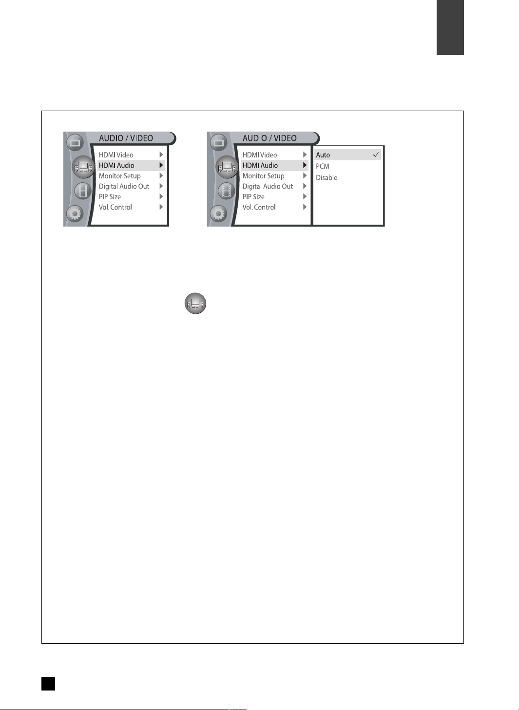
HDMI Audio
Audio / Video
09
Control HDMI audio output.
1. Press MENU button.
2. Use ▲,▼ button to highlight ‘’icon, then press OK.
3. Use ▲,▼ button to highlight ‘HDMI Audio’, then press OK.
4. Press ▲, ▼ button to make a choice, then press OK.
ㆍ Auto : If the broadcaster is broadcasting PCM/MPEG, the Digital OUT will be PCM. If the broadcaster
is broadcasting Dolby Digital, the Digital OUT will be Dolby Digital.
ㆍ PCM : Whatever the broadcaster is broadcasting (PCM/MPEG or Dolby Digital), the Digital OUT will
be at PCM.
ㆍ DISABLE : Select this, in order to have Digital Audio OUT in Dolby Digital for using external amplifier
at below conditions.
– The TV digital audio support only PCM, and HDMI cable is used.
– The broadcaster is broadcasting Dolby Digital.
When you connect using HDMI cable, the digital audio in the TV is detected. So if it detects PCM,
then the Digital OUT will be at PCM too. If it detects Dolby Digital, then the Digital OUT will be at
Dolby Digital too.
※ Press MENU button to exit the menu screen.
※ Press EXIT button to switch to previous step on the menu screen.
Page 46

Adjust display position.
1. Press MENU button.
2. Use ▲,▼ button to highlight ‘’icon, then press OK.
3. Use ▲,▼ button to highlight ‘Monitor Setup’, then press OK.
4. Customize the Monitor type to fit user’s TV or display.
ㆍ16 : 9
ㆍ4 : 3
※ Press MENU button to exit the menu screen.
※ Press EXIT button to switch to previous step on the menu screen.
09
44
Audio / Video
Monitor Setup
Page 47

45
Audio / Video
09
Digital Audio Out
1. Press MENU button.
2. Use ▲,▼ button to highlight ‘’icon, then press OK.
3. Use ▲,▼ button to highlight ‘Digital Audio Out.’, then press OK.
4. Use ▲,▼ button to make a choice, then press OK.
ㆍPCM : Digital Audio Output is always PCM.
ㆍDolby D : Digital Audio Output is Dolby Digital in case of Dolby Digital audio stream come in.
Controls audio output type.
※ Press MENU button to exit the menu screen.
※ Press EXIT button to switch to previous step on the menu screen.
Page 48

Set up the PIP size.
※ Press MENU button to exit the menu screen.
※ Press EXIT button to switch to previous step on the menu screen.
09
46
Audio / Video
PIP Size
1. Press MENU button.
2. Use ▲,▼ button to highlight ‘’icon, then press OK.
3. Use ▲,▼ button to highlight ‘PIP Size’, then press OK.
4. Press ▲, ▼, ◀, ▶ button to make a choice, then press OK.
ㆍPIP size can be chosen from ‘Large’, ‘Medium’, or ‘Small’.
Page 49

Audio / Video
47
09
Vol. Control
1. Press MENU button.
2. Use ▲,▼ button to highlight ‘’icon, then press OK.
3. Use ▲,▼ button to highlight ‘Vol. Control’, then press OK.
4. Use ▲,▼ button to make a choice, then press OK.
ㆍOFF : Volume of the STB can NOT be controlled by remote control.
ㆍON : Volume of the STB can be controlled by remote control.
※ When the volume is off, the MUTE button will operate as normal. However you will not be able to
control volume.
※ Press MENU button to exit the menu screen.
※ Press EXIT button to switch to previous step on the menu screen.
Turn on and off the remote controller volume control functionality.
Page 50

10
48
PVR Manager
Program List
The Program List shows the recorded programs.
(You can also bring up the Program List by pressing the P.LIST button on the remote control.)
1. Press MENU button.
2. Use ▲,▼ button to highlight ‘’icon, then press OK.
3. Use ▲,▼ button to highlight ‘Program List’, then press OK.
4. On the Program List, press ◀, ▶ button to select a program.
5. Press OK button to playback the selected program.
6. Press ◀ button to delete the selected program.
7. Press ▶ button to add the selected program.
※ The selected program for deleting will be erased when exit the program list menu. The program can
be added again only before erased.
※ If you play any program in Program List Menu, the timeshift will be automatically terminated.
※ Press MENU button to exit the menu screen.
※ Press EXIT button to switch to previous step on the menu screen.
Page 51

PVR Manager
49
10
Skip Time
1. Press MENU button.
2. Use ▲,▼ button to highlight ‘’icon, then press OK.
3. Use ▲,▼ button to highlight ‘Skip Time’, then press OK.
4. Press ▲, ▼ button to make a choice, then press OK.
※ Press MENU button to exit the menu screen.
※ Press EXIT button to switch to previous step on the menu screen.
Set up how much time will be skipped when user press SKIP+, SKIP- button.
Page 52

50
PVR Manager
10
HDD Sleep Time
Set up how much time the HDD will be powered on after the HDD has no works to do.
1. Press MENU button.
2. Use ▲,▼ button to highlight ‘’icon, then press OK.
3. Use ▲,▼ button to highlight ‘HDD Sleep Time’, then press OK.
4. Press ▲, ▼ button to make a choice, then press OK.
※ In HDD Auto Sleep mode, if HDD is not used for 3 minutes, the HDD will enter into sleep mode.
When you want to use HDD again, it will take 2 or 3 seconds to escape from HDD sleep mode.
※ Press MENU button to exit the menu screen.
※ Press EXIT button to switch to previous step on the menu screen.
Page 53

51
PVR Manager
10
HDD Format
Formats the HDD. All the recorded programs will be deleted.
1. Press MENU button.
2. Use ▲,▼ button to highlight ‘’icon, then press OK.
3. Use ▲,▼ button to highlight ‘HDD Format’, then press OK.
4. Enter password to proceed.
5. Press OK to start HDD format.
Caution
If you format the HDD, everything recorded on the HDD will be erased.
※ The factory default password is 0–0–0–0.
※ For any reason, if you forget the password, Press MENU, CC, 3,6,9 button sequentially, then the
password will be back to ‘0000’ again.
※ Press MENU button to exit the menu screen.
※ Press EXIT button to switch to previous step on the menu screen.
Page 54

52
System
11
Opacity
Control opacity (transparent) of menu screen.
1. Press MENU button.
2. Use ▲,▼ button to highlight ‘’icon, then press OK.
3. Use ▲,▼ button to highlight ‘Opacity’, then press OK.
4. Press ▲,▼ button to make a choice, then press OK.
ㆍOpacity1 : Very Dark
ㆍOpacity2 : Dark
ㆍOpacity3 : Light
ㆍOpacity4 : Very Light
※ Press MENU button to exit the menu screen.
※ Press EXIT button to switch to previous step on the menu screen.
Page 55

Time Zone
53
System
11
Select time zone.
1. Press MENU button.
2. Use ▲,▼ button to highlight ‘’icon, then press OK.
3. Use ▲,▼ button to highlight ‘Time Zone’, then press OK.
4. Use ▲,▼ button to make a choice, then press OK.
ㆍNSW/ACT
ㆍVIC/TAS
ㆍQLD
ㆍSA
ㆍWA
ㆍNT
ㆍAuto Time Zone
※ If the automatic clock setting is not correct, go to the channel that broadcasting teletext and press TTX button.
※ Press MENU button to exit the menu screen.
※ Press EXIT button to switch to previous step on the menu screen.
Page 56

54
System
11
Daylight Saving
Select daylight saving.
1. Press MENU button.
2. Use ▲,▼ button to highlight ‘’icon, then press OK.
3. Use ▲,▼ button to highlight ‘Daylight Saving’, then press OK.
4. Use ▲,▼ button to make a choice, then press OK.
ㆍOff : Daylight Saving is off.
ㆍOn : Daylight Saving is on.
※ If you select ‘Auto time Zone’, Daylight Saving On/Off does not work.
※ If the automatic clock setting is not correct, go to the channel that broadcasts teletext and press TTX button.
※ Press MENU button to exit the menu screen.
※ Press EXIT button to switch to previous step on the menu screen.
Page 57

Sleep Timer
55
System
11
Select the time in which the unit is to be turned off.
1. Press MENU button.
2. Use ▲,▼ button to highlight ‘’icon, then press OK.
3. Use ▲,▼ button to highlight ‘Sleep Timer’, then press OK.
4. Use ▲,▼ button to make a choice, then press OK.
※ Press MENU button to exit the menu screen.
※ Press EXIT button to switch to previous step on the menu screen.
Page 58

56
System
11
New Password
Change the 4-digit password.
1. Press MENU button.
2. Use ▲,▼ button to highlight ‘’icon, then press OK.
3. Use ▲,▼ button to highlight ‘NEW PASSWORD’icon, then press OK.
4. Enter password to proceed.
5. Enter new password and make a confirmation using number keys on the remote controller.
※ The factory default password is 0-0-0-0.
※ For any reason, if you forget the password, Press MENU, CC, 3,6,9 button sequentially, then the
password will be back to ‘0000’ again.
※ When the program rating exceeds the level set on this menu, you will see the OSD above and audio
and video will be blocked. Enter password to watch the program. The pass state will be valid until power is off.
※ Press MENU button to exit the menu screen.
※ Press EXIT button to switch to previous step on the menu screen.
Page 59

Factory Default
57
System
11
Set Factory Default.
1. Press MENU button.
2. Use ▲,▼ button to highlight ‘’icon, then press OK
3. Use ▲,▼ button to select Factory Default, then press OK.
4. Enter password to proceed.
5. Press OK button to set to Factory Default.
※ The factory default password is 0-0-0-0.
※ For any reason, if you forget the password, Press MENU, CC, 3,6,9 button sequentially, then the
password will be back to ‘0000’ again.
※ Set to Factory Default takes 25 second.
※ Don’t Power Off during set to Factory Default.
※ Press MENU button to exit the menu screen.
※ Press EXIT button to switch to previous step on the menu screen.
Page 60

About
58
System
11
Show the software version and date.
1. Press MENU button.
2. Use ▲,▼ button to highlight ‘’icon, then press OK.
3. Use ▲,▼ button to highlight ‘About’, then press OK.
4. Use ▲,▼ button to make a choice, then press OK.
※ Press MENU button to exit the menu screen.
※ Press EXIT button to switch to previous step on the menu screen.
Page 61

59
Specifications
12
Specifications
SPECIFICATIONSITEM
Antenna input 2ea & Loop Output 2ea
Component (Y, Pb, Pr) Output 1set
HDMI/DVI Output 1ea
RGB/HV Output 1ea
S-Video Output 1ea
Composite Output 1ea
Digital Audio Output (Optical) 1ea
Digital Audio Output (Coaxial) 1ea
Analog Audio Output (L/R) 2 sets
Service Port (RS232-C) 1ea
Input/Output
(NHD-3000PVR)
Product Name
Mode
l
Supply Voltage
Power Consumption
Size (W X H X D)
Weight (Kg)
Channel
Antenna Impedance
NHD-3000PVR
AC 240V, 50Hz
Operation : 25W max, Standby : 1W max
335mm x 65mm x 270mm
NET : 3.0 Kg, GROSS : 4.2 Kg
Band-III(137-230MHz), Band-IV(519-820MHz)
High Definition Receiver / Recorder
75Ω
Page 62

NEC Service Centres
NEC Australia Pty. Ltd.
ABN 86 001 217 527
DISPLAY AND HOME GROUP
New South Wales
Sydney 184 Milperra Rd, Revesby 2212 131-632
Newcastle 120 Parry Street, Newcastle West 2302 131-632
Victoria
Melbourne Unit 1/6, Garden Road, Clayton, 3168 131-632
Queensland
Brisbane Unit 4/305 Montague road, West End, 4101 131-632
Southport Shop 1, 48 Ferry Road, Southport 4215 131-632
South Australia
Adelaide 84A Richmond Rd, Keswick, 5053 131-632
Western Australia
Perth 45 Sarich Court, Osborne Park 6017 131-632
For Service in outer areas, please contact your NEC retailer for the address of the nearest Authorised NEC
Service Centre.
NEC Australia Pty. LTD.
DISPLAY AND HOME GROUP
244 Beecroft Road EPPING 2121
Tel: 131-632
Fax: (02) 9877 2353
60
Page 63

 Loading...