

Page 1
A
NF2300-SE41E
Additional Disk Enclosure
User's Guide
NOTE:
Read this manual carefully before using the unit. Keep this
manual nearby as a handy reference and refer to the
"CAUTION" and "WARNING" statements whenever necessary.
NEC CONFIDENTIAL AND PROPRIETARY
All rights reserved by NEC Corporation. This document must be
used solely for the purpose for which it was furnished by NEC
Corporation. No part of this document may be reproduced or
disclosed to others, in any form, without the prior written
permission of NEC Corporation.
856-850305-102-
Page 2
FEDERAL COMMUNICATIONS COMMISSION
RADIO FREQUENCY INTERFERENCE STATEMENT
NOTE: This equipment has been tested and found to comply with the limits for a Class A
digital device, pursuant to Part 15 of the FCC Rules. These limits are designed to
provide reasonable protection against harmful interference when the equipment is
operated in a commercial environment. This equipment generates, uses, and can radiate
radio frequency energy and, if not installed and used in accordance with the instruction
manual, may cause harmful interference to radio communications. Operation of this
equipment in a residential area is likely to cause harmful interference in which case the
user will be required to correct the interference at his own expense.
Warning
This is a Class A product. In domestic environment this product may cause radio
interference in which case the user may be required to take adequate measures.
Page 3
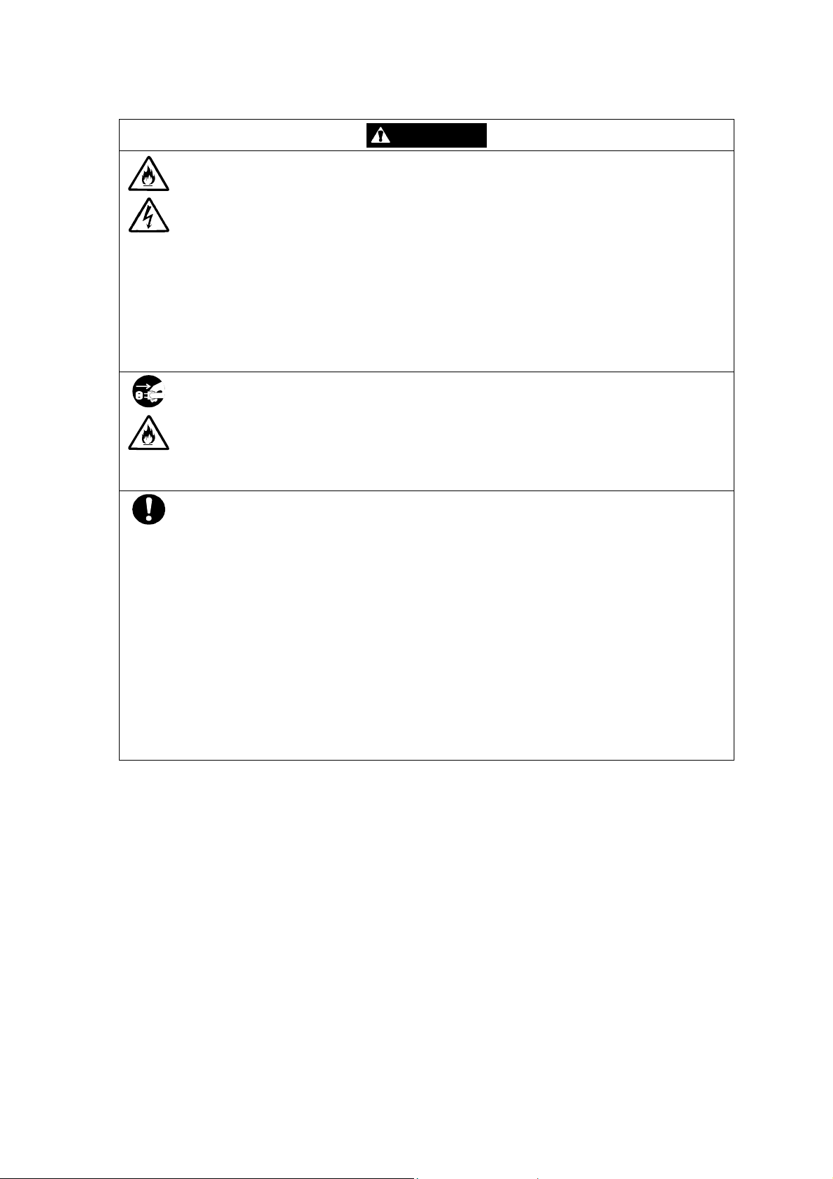
Safety Precautions
Before using this unit, read this manual carefully and keep cautions in order to use this
unit safely and correctly and to avoid to be a cause of damage to the body or properties.
Keep this manual to see whenever it is necessary.
The following symbols are used in this manual so that you can easily understand how to
operate the unit safely and correctly.
WARNING
CAUTION
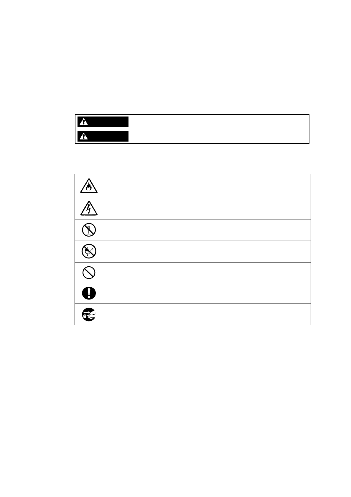
Risks and necessary actions to reduce risks are indicated individually by the following
symbols.
Indicates the risk of smoke emission or fire outbreak.
Indicate there is a risk of death or serious wound.
Indicate there is a risk of burn or injury.
Indicates the risk of electric shock.
Indicates the danger of an injury due to harmful material.
Indicates instructions to keep a device away from inflammable object.
Indicates notice of general prohibition.
Indicates required general actions for operators.
Indicates instructions to pull the plug of a power cord from outlet and to off
main circuit breaker.
- i -
Page 4
Notes on Use
The following includes information necessary for proper and safe operation of the
additional disk enclosure.
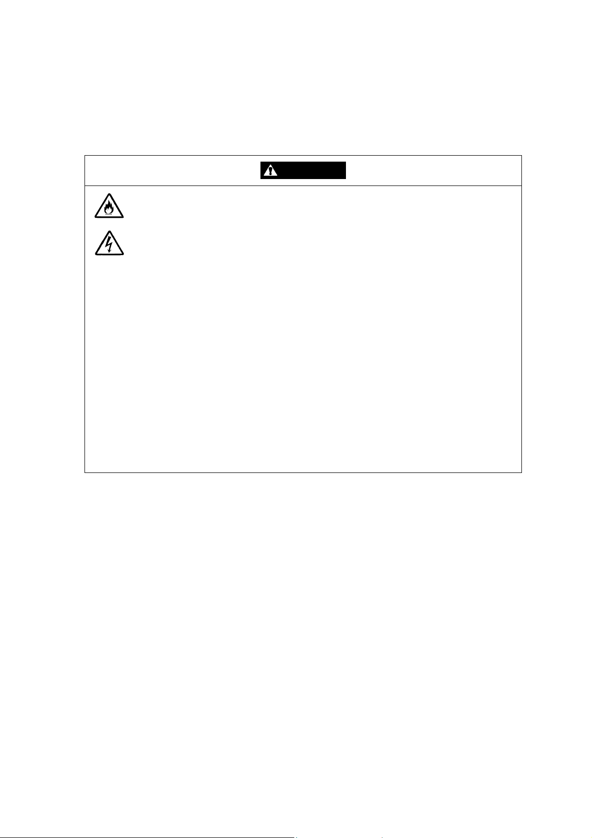
WARNING
Do not use the additional disk enclosure in an area with much moisture or water
usage. If so, a fault, electrical shock, or fire may occur.
Do not use the additional disk enclosure in an area where inflammable gas and/or
combustible substance are placed. If so, fire or explosion may occur.
Do not concentrate power cords only to some AC outlets. If so, fire may occur.
Do not put a heavy substance on a power cord. If so, the coating of the power
cord may be broken, fire may occur, and/or you may be electrically shocked.
Do not install the additional disk enclosure in an area of much moisture or dust.
Remove dust adhering to AC outlets and the plugs of power cords, if any. If dust
remains adhering to an AC outlet and/or plug, fire may occur.
Do not connect the plug of a power cord to an AC outlet with a wet hand. If so, you
may be electrically shocked.
While the additional disk enclosure can accept the power of 100 - 240 VAC (50/60
Hz), the power cord coming with the additional disk enclosure can only accept 100
- 120 VAC. Use 100 - 120 VAC (50/60 Hz) when the attached power cord is used.
Using power of different voltage may cause electric shock, smoke, and/or fire to
occur.
- ii -
Page 5
CAUTION
Do not install the additional disk enclosure and disk array unit on an unstable place.
If so, some substances may be dropped to cause you to be injured.
Do not install the additional disk enclosure and the power cords in an area with
direct sunshine or near an apparatus generating heat such as a heater. If so, a fault
may occur. Further, the coating of the power cord may be melted to cause fire or
electric shock to occur.
Insert the plug of a power cord to an AC outlet securely. Any power cord shall be
routed with sufficient margin to avoid excess force from being given to the plugs of
the power cord or the power cord itself. If a power cord is removed from the AC
outlet during operation, data may be lost and/or a fault may occur.
To prevent electric shocks, connect a power cord to an AC outlet with earth
terminal. Connection of the earth line to a gas tube is extremely dangerous. Never
do it.
Connect or remove a peripheral from the additional disk enclosure after turning off
all the powers of the additional disk enclosure and peripherals and pulling out the
power cords from the AC outlets. If not, some units may be broken and/or you may
be electrically shocked.
To carry or reinstall the additional disk enclosure, disconnect all cables and power
cords connected to the additional disk enclosure beforehand.
If not, a malfunction of the system, an electric shock and/or fire may occur.
To install the unit in a rack, observe the following guidelines.
1. TMRA – If installed in a rack, consideration should be given to installing the
equipment in an environment compatible with the TMRA.
2. Reduced Air Flow – Installation in a rack should be such that the amount of air flow
required for safe operation of the equipment is not compromised.
3. Mechanical loading – Mounting of the equipment in the rack should be such that a
hazardous condition is not achieved due to uneven mechanical loading.
4. Circuit Overloading – Consideration should be given to the connection of the
equipment to the supply circuit and the effect that overloading the circuits might
have on overcurrent protection and supply wiring. Appropriate consideration of
equipment nameplate ratings should be used when addressing this concern.
5. Reliable Earthing – Reliable earthing of rack-mounted equipment should be
maintained. Particular attention should be given to supply connections other than
direct connections to the branch circuit (e.g., use of power strips).
- iii -
Page 6
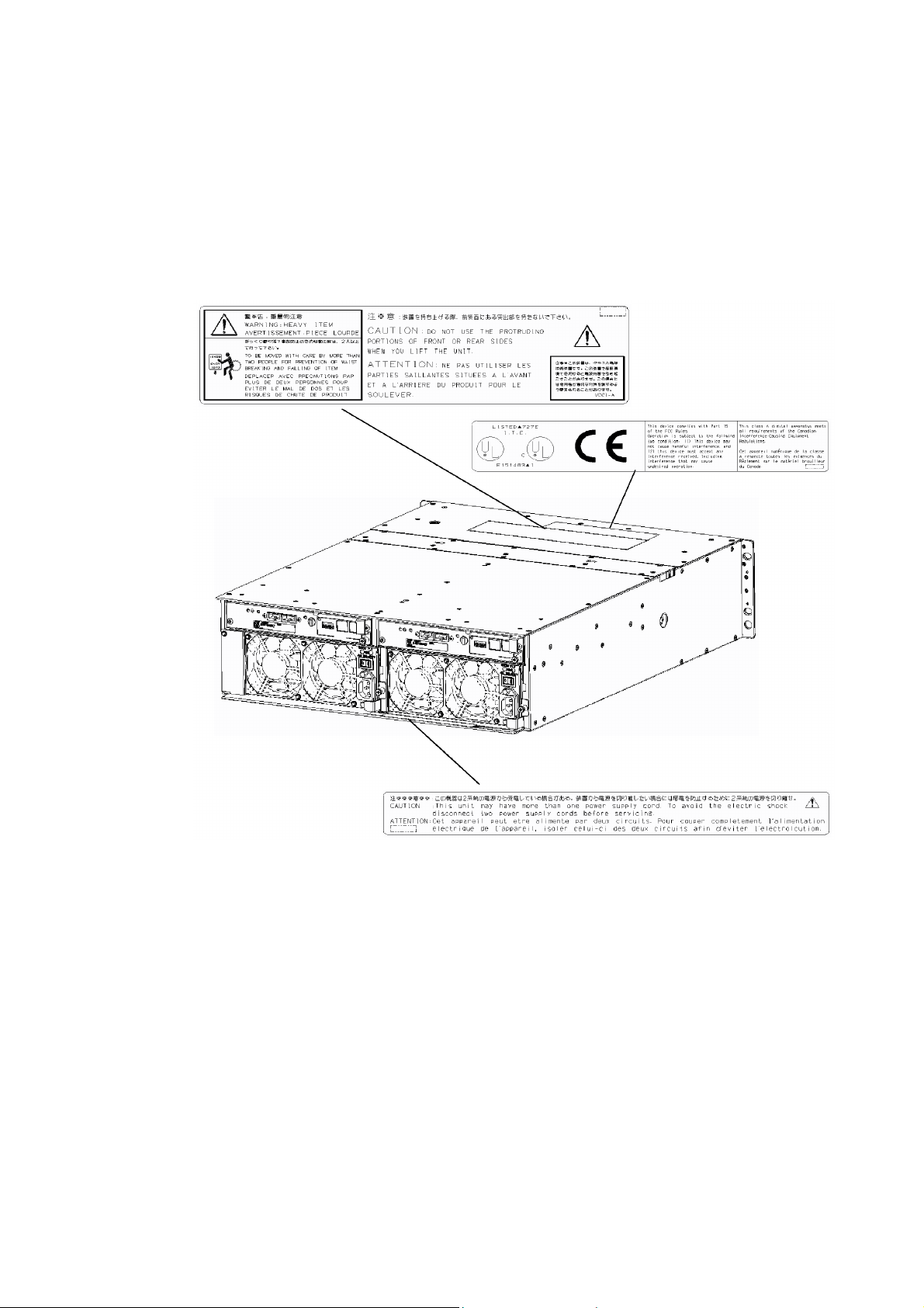
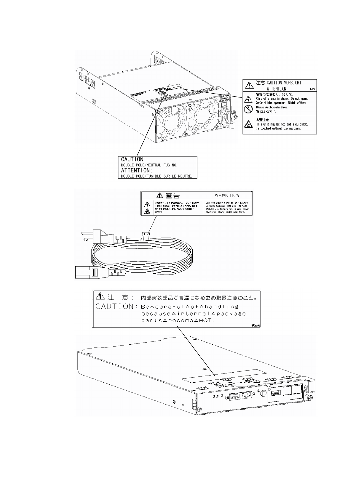
Indication on Safety
Warning labels are put on parts possibly be dangerous and/or surroundings in the
additional disk enclosure. They are intended to always make you conscious of possible
dangers when you handle the additional disk enclosure. (Do not peel off the labels or do
not make them dirty.) If any of the labels is not put on the proper position, is peeled off a
little, or is dirty to make it unreadable, contact your sales agent or maintenance engineer.
- iv -
Page 7
- v -
Page 8

Trademarks
Microsoft, Windows, Windows NT, and Windows 2000 are registered trademarks of
Microsoft Corporation in the United States and other countries.
HP-UX is a registered trademark of Hewlett-Packard Company of the United States.
Solaris is a trademark or registered trademarks of Sun Microsystems, Inc. in the United
States and other countries.
All other product, brand, or trade names used in this publication are the trademarks or
registered trademarks of their respective trademark owners.
Momentary voltage drop prevention
This product may be affected by a momentary voltage drop caused by lightning. To
prevent a momentary voltage drop, an AC uninterruptive power supply (UPS) unit should
be used.
Notes
(1) No part of this manual may be photocopied in any form without prior written
consent from NEC.
(2) The information in this manual is subject to change without notice.
(3) All possible efforts are being made to create this manual, but in the event that any
technical or editorial errors or omissions are found, contact your dealer.
(4) Keep this manual in a convenient area even after you finished reading it.
(5) When transferring this unit to other person, be sure to transfer this manual also.
(6) NEC shall not be liable for any loss or lost profits from the use of this unit regardless
of the item in (3).
(7) This unit is not intended to be installed into the installation or equipment associated
with human life, such as medical equipment, atomic installation or equipment, aerial
and space equipment, transportation installation and equipment and to be installed
into and to control the installation or equipment requiring high reliability. If you use
this unit for these installation, equipment, or control system, NEC shall not be liable
for an accident leading to an injury or death, fire, or social loss resulting from a
breakdown of our product.
© 2003 NEC Corporation
No part of this manual may be photocopied or modified in any form without prior written
consent from NEC.
- vi -
Page 9

Preface
Thank you very much for your purchase of the additional disk enclosure.
The manual describes the operations and notes on use of Additional Disk Enclosure
NF2300-SE41E available for the NF2300-SR4xxE disk array unit to be connected to NEC
Express5800, NX7000, or CX5000 series system.
Before using NF2300-SE41E, also read the manuals of the connected Express5800 series,
FibreChannel controller, NX7000 series, FC-AL SCSI connection mechanism, CX5000
series, and disk array unit and the manual of the used OS to enable the full ability of the
additional disk enclosure to be brought.
The NF2300-SE41E additional disk enclosure is provided with the following options;
additional 36GB disk drive NF2300-SM412E, additional 73GB disk drive
NF2300-SM413E, additional 147GB disk drive NF2300-SM414E, additional
36GB/15Krpm disk drive NF2300-SM422E, and rack-mount kit NF9100-SK01E,
NF9100-SK02E, and NF9100-SK03E.
After reading the document, keep it carefully in a place where you can take it if required.
First edition, February 2003
- vii -
Page 10

Check of Components in Package
(1) Unpacking
Open the package and take out the additional disk enclosure and accessories from the
package without large shock. The additional disk enclosure is greatly heavy.
Accordingly, if two people or less lift the unit, their back may be damaged. To take
out the additional disk enclosure from the package, more than three people should
always support the bottom of the unit without holding the power supply on the rear
face and the projections of the adapter.
The package is specially designed for carriage of a precision device. Do not dispose
of the package because it is required to return the additional disk enclosure to the
factory for its repair.
(2) Inspection
After unpacking, check that all the components listed in the table below are
provided. If any of the components is missed, contact your sales agent. Next, inspect
the additional disk enclosure and accessories. If any of the components is damaged,
contact your sales agent.
No. Product name Remarks Qty
1 Additional Disk Enclosure 1
2 Power cord Length 5 m (for 100 - 120 VAC) 2
3 HSSDC cable Length 1m 2
4 DE diagnosis cable Length 1m 2
5 Front mask 1
6 Key 1
7 User's Guide (this document) 1
8 Packing list 1
9 Location label 1
10 Rack mount kit For NEC Storage rack (L and R) 1
* Use the HSSDC cable and DE diagnosis cable provided with the additional disk
enclosure for connecting disk array unit NEC Storage S2300 with the additional
disk enclosure. A DE cable set (NF9120-SJ04E), which is separately priced, may
be used instead of the provided cables.
- viii -
Page 11
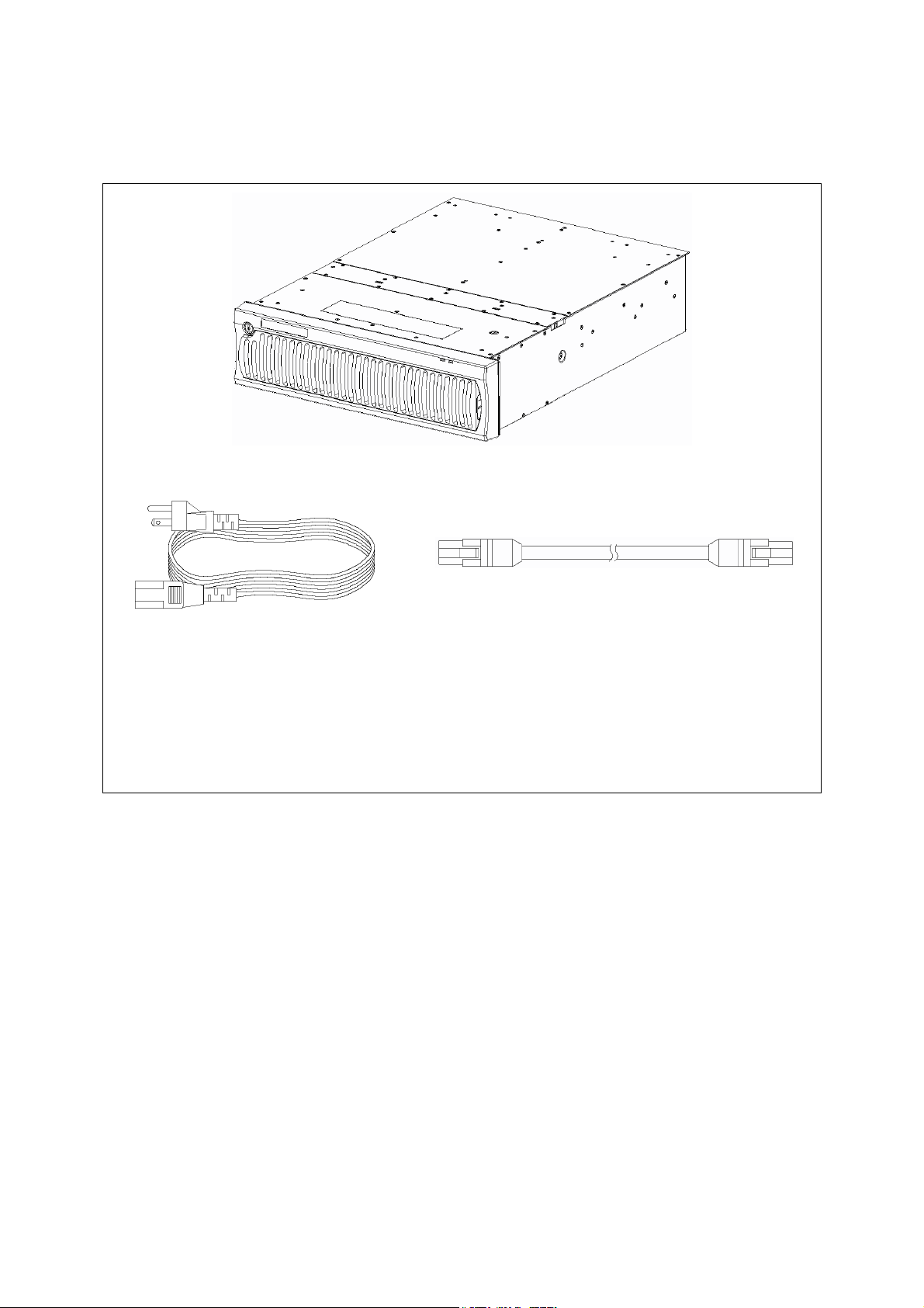
NF2300-SE41E
(1) Additional disk enclosure (The figure above shows the unit with the front mask installed.)
(2) Power cord (3) HSSDC cable
(4) DE diagnosis cable (5) Front mask
(6) Key (7) User's guide (This document)
(8) List of accessories (9) Location label
(10) Rack mount kit
- ix -
Page 12
Legend
Symbols in the Text
This User's Guide uses the following symbols to indicate improper handling which may
cause the additional disk enclosure to be defected or frozen.
Symbol Description
If the description is ignored to handle the additional disk enclosure incorrectly, the
unit may be defected, some software used in the unit may be broken, and/or the
data created by the user may be broken.
If the description is ignored to handle the additional disk enclosure incorrectly, the
unit may be defected and/or some software used in the unit may not operate
normally.
This User's Guide also uses the following symbol.
Symbol Description
Supplement of the text
This User's Guide uses the following terms to indicate specific devices.
Additional disk enclosure Indicates the additional disk enclosure NF2300-SE41E.
Disk array unit Indicates NF2300-SR4xxE NEC Storage S2300 1/2 and 2/2.
Array controller Indicates NF2300-SR4xxE NEC Storage S2300 1/2.
Disk enclosure Indicates the NF2300-SR4xxE NEC Storage S2300 2/2 and the
additional disk enclosure.
Disk drive Indicates the hard disk unit with dedicated tray.
Dummy tray Indicates the dedicated tray only, with no hard disk installed.
Host system Indicates the NEC Express5800 series, NX 7000 series, or CX5000
series.
Host bus adapter Indicates the FibreChannel controller for NEC Express5800 series,
FC-AL SCSI connection mechanism for NX7000 series, or
FibreChannel controller for CX5000 series.
- x -
Page 13

Contents
Notes on Use ..................................................................................................... ii
Indication on Safety........................................................................................... iv
Preface ............................................................................................................ vii
Check of Components in Package .................................................................. viii
Legend...............................................................................................................x
1. NOTES ON INSTALLATION AND HANDLING OF ADDITIONAL DISK
ENCLOSURE ...............................................................................................1
1.1 Note on Carrying Additional Disk Enclosure ........................................1
1.2 Environment in Use of Additional Disk Enclosure ................................2
1.3 Installation and Connection of Additional Disk Enclosure.....................3
1.4 Notes on Use of Additional Disk Enclosure..........................................5
1.5 Routine Inspection of Additional Disk Enclosure..................................6
1.6 Notes on Storage or Carriage of Additional Disk Enclosure.................6
2. FEATURES OF ADDITIONAL DISK ENCLOSURE ......................................7
3. NAMES AND ROLES OF SECTIONS ..........................................................8
3.1 Disk Enclosure (Front).........................................................................8
3.2 Disk Enclosure (Rear)........................................................................10
3.3 Power Supply for Disk Enclosure.......................................................11
3.4 Adapter..............................................................................................13
4. INSTALLATION AND CONNECTION PROCEDURES ...............................15
4.1 Installation and Connection Procedures ............................................15
5. CONNECTION OF ADDITIONAL DISK ENCLOSURE ...............................16
5.1 Notes on Connection of Additional Disk Enclosure ............................17
5.2 Connection of Additional Disk Enclosure ...........................................18
5.3 Connection of Power Cords...............................................................25
6. ADDITION OF OPTIONAL DEVICES.........................................................27
6.1 Addition of Disk Drive ........................................................................27
7. HANDLING OF ADDITIONAL DISK ENCLOSURE.....................................32
7.1 Notes on Handling of Additional Disk Enclosure ................................32
7.2 Power On/Off of Additional Disk Enclosure........................................33
7.3 LD (Logical Disk) Setting Procedure..................................................39
7.4 Spare Disk Setting Procedure............................................................39
- xi -
Page 14

8. ACTION TAKEN AT OCCURRENCE OF FAULT OR ERROR ...................40
8.1 Countermeasures Taken when Occurrence of a
Fault is Suspected ............................................................................41
8.2 Indication at Occurrence of Fault .......................................................43
8.3 Fault of Disk Drive .............................................................................44
8.4 Fault of Power Supply for Disk Enclosure..........................................47
8.5 Fault of Adapter.................................................................................51
8.6 Check of Type Name and Manufacturing Numbers ...........................54
8.7 Preparation before Phone Call...........................................................55
8.8 Service and Support ..........................................................................55
8.9 Unit Life/Repair Service Period..........................................................55
8.10 Disposal of Additional Disk Enclosure................................................55
9. PRODUCT SPECIFICATION......................................................................56
9.1 Basic Specification of Additional Disk Enclosure................................56
9.2 Optional Components........................................................................56
9.3 Environmental Conditions of Additional Disk Enclosure.....................56
9.4 Power Specification...........................................................................57
9.5 External Dimension and Weight of Additional Disk Enclosure............57
- xii -
Page 15
1. NOTES ON INSTALLATION AND HANDLING OF ADDITIONAL DISK ENCLOSURE
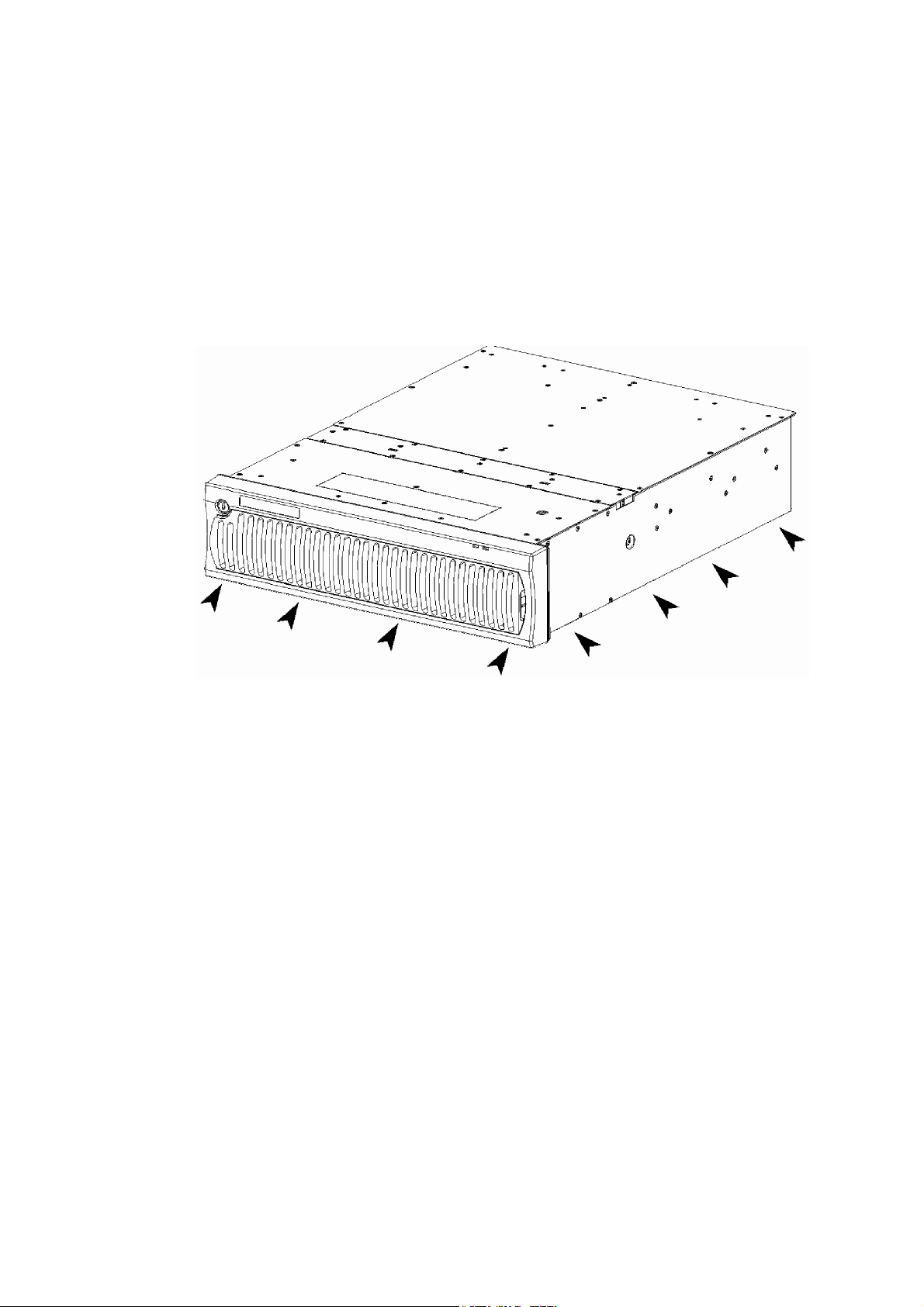
1.1 Note on Carrying Additional Disk Enclosure
Be sure to hold the bottom the additional disk enclosure when carrying it.
Hold the front or side bottom of the additional disk enclosure if possible.
- 1 -
Page 16
1.2 Environment in Use of Additional Disk Enclosure
In installation of the additional disk enclosure, take into account the following items on
the location, room temperature, space required for handling, ventilation, and other
conditions.
Install the additional disk enclosure indoors.
Do not expose the additional disk enclosure to direct sunlight. Use a window
shade or curtain to block sunlight to the unit if necessary.
Install the additional disk enclosure on a level floor with sufficient strength. In
addition, do not give shocks and/or vibrations to the additional disk enclosure.
If so, some components may be dropped to cause the additional disk
enclosure to be defected and/or people to be injured.
Install the additional disk enclosure in an area under the following conditions;
temperature range between 5°C - 40°C and humidity range between 10% 80% (without condensation).
Do not install the additional disk enclosure in an area with water or oil poured,
area suffering liquid such as water and oil, suffering steam, area with steam,
and area with much moisture. If not, a malfunction of the system, or an electric
shock may occur.
Do not install the additional disk enclosure in an area with emission of
chemical steam or an area where the additional disk enclosure may be contact
with inflammable substance. If so, a fault, fire, or explosion may occur.
Do not install the additional disk enclosure in an area with much dust. If so, a
fault may occur.
Do not install the additional disk enclosure in an area with direct sunshine or
near fire or an apparatus generating heat such as stove. If so, a fault or
deformation may occur.
Do not install the additional disk enclosure near TV, radio, and codeless
telephone. Some noise may appear in the TV, radio, and codeless telephone.
Do not use cellular phones near the additional disk enclosure. If so, a fault may
occur.
Do not install the additional disk enclosure near a device generating strong
magnetism. If so, a fault may occur.
Install the additional disk enclosure so that the ventilating holes opened on the
front and rear faces are not blocked. If not, heat generation and/or fault may
occur.
- 2 -
Page 17
1.3 Installation and Connection of Additional Disk Enclosure
WARNING
Do not use the additional disk enclosure in an area with much moisture or
water usage. If so, a fault, electrical shock, or fire may occur.
Do not use the additional disk enclosure in an area where inflammable gas
and/or combustible substance are placed. If so, fire or explosion may occur.
Do not install the additional disk enclosure in an area of much moisture or
dust. Remove dust adhering to AC outlets and the plugs of power cords, if
any. If dust remains adhering to an AC outlet and/or plug, fire may occur.
Do not concentrate power cords only to some AC outlets. If so, fire may
occur.
Do not put a heavy substance on a power cord. If so, the coating of the power
cord may be broken, fire may occur, and/or you may be electrically shocked.
Do not connect the plug of a power cord to an AC outlet with a wet hand. If
so, you may be electrically shocked.
CAUTION
Make sure to disconnect all power cords and FC cables before relocating the
additional disk enclosure. If not, a malfunction of the system, an electric
shock and/or fire may occur.
While the additional disk enclosure can accept the power of 100 - 240 VAC
(50/60 Hz), the power cord coming with the additional disk enclosure can only
accept 100 - 120 VAC. Use 100 - 120 VAC (50/60 Hz) when the attached
power cord is used. Using power of different voltage may cause electric
shock, smoke, and/or fire to occur.
Do not install the additional disk enclosure and the power cords in an area
with direct sunshine or near an apparatus generating heat such as a heater. If
so, a fault may occur. Further, the coating of the power cord may be melted to
cause fire or electric shock to occur.
- 3 -
Page 18
The additional disk enclosure weighs 34 kg or more. Hold the disk enclosure
firmly with at least three people to carry it. Carrying the additional disk
enclosure only by two or less people may strain their back.
Select the place where the additional disk enclosure can be connected to the
AC outlet by using the attached power cord or the power cord approved by
NEC.
Insert the plug of a power cord into an AC outlet securely. If some clearance
remains between the plug of the power cord and the AC outlet, dust may
enter into the clearance. This then may cause fire to occur.
Provide sufficient margins for the cables connected to the additional disk
enclosure so that legs may not be trapped by the cables. Avoid power plugs
and FC connectors from suffering excess forces.
Do not use cables connected to the additional disk enclosure with them
leaving bent. If so, a fault or fire may occur.
Use the cables approved by NEC as those connected to the additional disk
enclosure and check the destinations to which the cables are connected. In
addition, always lock power cords and FC cables when they are connected.
Use the power source independent from TV or radio. Otherwise, a noise may
be generated.
To connect a cable to the mating connector, make sure that the connector of
the cable is not damaged and any pins are not bent. Using a cable not
approved by NEC or a damaged cable may cause fire to occur.
To disconnect a cable from the mating connector, always hold the connector
of the cable. Do not hold the cable itself to disconnect it.
- 4 -
Page 19
1.4 Notes on Use of Additional Disk Enclosure
Do not let any animal (pet) or children touch the cable connected to the
additional disk enclosure. Pulling the cable may cause the unit to fall down,
resulting in failure of the unit.
Do not enter any liquid such as water into the additional disk enclosure. If so,
you may be electrically shocked or the unit may be defected. If some liquid is
entered into the additional disk enclosure, turn off the power and contact your
sales agent or maintenance engineer. If the additional disk enclosure seems
dry, only a small amount of liquid may remain to cause the unit to be defected.
Do not enter foreign substances such as clip and screw into the additional disk
enclosure through the ventilating holes on the front or rear face. If so, a fault
may occur.
Do not disassemble or modify the additional disk enclosure. If so, a fault or
electrical shock may occur.
If the additional disk enclosure will not be used for a long period, disconnect
the plugs of the power cords from the AC outlets for safety.
Disconnect the power plug from the outlet when a thunderstorm is
approaching. If it starts thundering before you disconnect the power plug, do
not touch any part of the unit including the cables. If any failure is found later,
contact your sales agent.
- 5 -
Page 20
1.5 Routine Inspection of Additional Disk Enclosure
CAUTION
To clean the additional disk enclosure, always turn off the power and also
disconnect the plugs of power cord from AC outlets. If not, you may be
electrically shocked.
If a surface of the additional disk enclosure becomes dirt, wipe the surface
lightly with soft cloth. Wiping the surface by using chemicals such as
benzene and thinner, or volatile chemicals, may cause the surface to be
deformed or discolored. In addition, note that splaying insecticide on a
surface may cause the surface to be deformed or discolored.
It is recommended that the inside of the additional disk enclosure is
cleaned periodically. It is because dust may be accumulated after the
additional disk enclosure is used for a long time.
Contact your sales agent or maintenance engineer for the cleaning of the
inside of the additional disk enclosure. Users must not disassemble and/or
repair the additional disk enclosure because it is dangerous.
1.6 Notes on Storage or Carriage of Additional Disk Enclosure
Do not store the additional disk enclosure in an area where the
temperature may increase extremely or the difference between the warm
and cold states is considerably large. In addition, do not store the
additional disk enclosure in an area with much moisture or dust.
Note that foreign substances such as water and metals may not be
entered into the additional disk enclosure during storage. Using the
additional disk enclosure with some foreign substance left inside may
cause a fault, electrical shock, or fire to occur.
During the storage, do not put any substance on the additional disk
enclosure or do not place the additional disk enclosure on an area where
the unit may be dropped. To use the additional disk enclosure after
storage for longer than six months, it is recommended to contact your
sales agent or maintenance engineer for inspection and/or repair.
The additional disk enclosure weighs 34 kg or more. Hold the disk
enclosure firmly with at least three people to carry it. Carrying the
additional disk enclosure only by two or less people may strain their back.
Do not hold the projected section of the power supply or adapter located
on the rear of the disk enclosure. An access force applied to them may
cause a damage to the power supply or the adapter, or cause the
additional disk enclosure to fall down resulting in human injury.
Make sure to package the additional disk enclosure when transporting it
with the packing material that comes with the additional disk enclosure. A
vibration or shock generated during transportation may cause a
malfunction of the unit.
- 6 -
Page 21

2. FEATURES OF ADDITIONAL DISK ENCLOSURE
The additional disk enclosure has the following features.
NF2300-SE41E is a high-performance additional disk enclosure developed for the
NF2300-SR4xxE disk array unit connected to the NEC Express5800 basic processing
unit, NX7000 basic processing unit, or CX5000 basic processing unit.
The additional disk enclosure NF2300-SE41E is not equipped with disk drives at the
shipment. To use the additional disk enclosure, add disk drives sold separately.
Up to 15 disk drives can be installed in NF2300-SE41E.
The disk drives for disk array unit NF2300-SR4xxE can be added by connecting the
additional disk enclosure NF2300-SE41E (up to 13 disk enclosures, 210 disk drives).
The combination of the additional disk enclosure and disk array unit NF2300-SR4xxE
enables a defected disk drive to be replaced with a new one without system shutdown.
Further, the additional disk enclosure has the auto rebuild feature which automatically
starts data recovery after the replacement of the defected disk drive.
If a single disk drive is specified as the spare disk, the data in the defected disk drive can
be immediately recovered in the spare disk. The use of this hot spare feature as well as the
auto rebuild feature allows the data in the defected drive to be automatically recovered in
the spare disk as soon as a disk drive is defected. This improves the system reliability.
Refer to "NF2300-SR4xxE Disk Array Unit User's Guide" for details of hot spare feature.
Further, owing to the redundant configuration of the adapter and power supply, the entire
system is not shut down if any part of the system is defected during operation.
See Section 9.2 "Optional Components" for the product names and part numbers of
options.
- 7 -
Page 22
3. NAMES AND ROLES OF SECTIONS
This chapter describes the names and functions of the sections in the additional disk
enclosure.
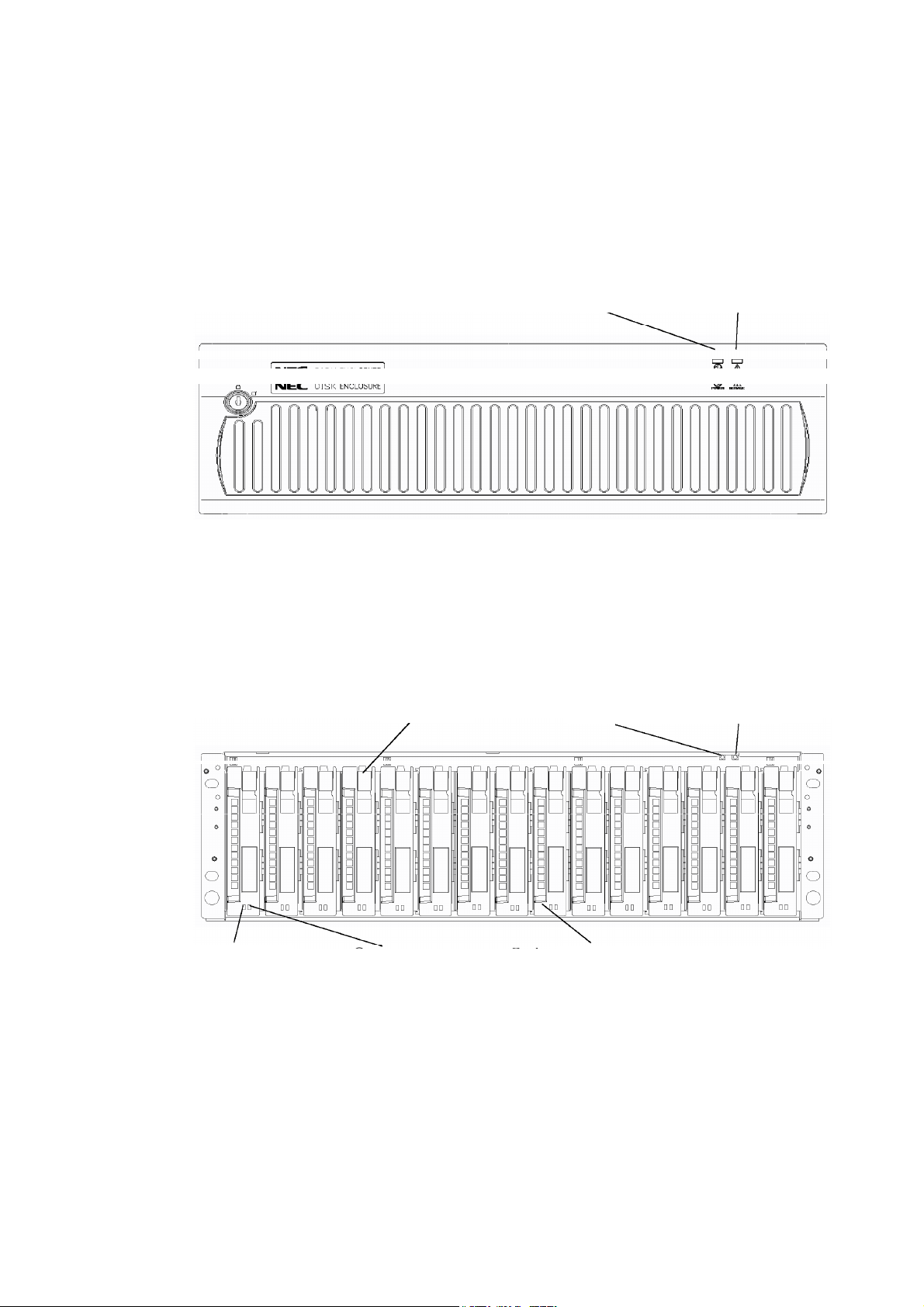
3.1 Disk Enclosure (Front)
(1) POWER LED (2) SERVICE LED
A front mask is installed on the front face of the additional disk enclosure as shown in the
figure above.
The front mask can be removed by releasing the lock with the accessory key and pulling
out toward you with your hands hooked on the both sides of the mask.
Removing the front mask, you can view the disk drives shown in the figure below.
(5) HDD FAULT LED
(6) Ejector
(4) HDD READY LED
(1) POWER LED
(3) Disk drives/dummy trays
(2) SERVICE LED
(1) POWER LED (green)
The POWER LED is lit green if the AC power is supplied and the power switch is
set to ON. The LED is off if the power switch is set to OFF.
- 8 -
Page 23

(2) SERVICE LED (orange)
The SERVICE LED goes on orange if an error occurs in the additional disk
enclosure.
The LED is off while the disk enclosure operates normally.
(3) Disk drive/dummy tray
Disk drive: Contains a hard disk drive (HDD) with the dedicated tray.
Dummy tray: Contains only the dedicated tray with no hard disk drive.
* The additional disk enclosure NF2300-SE41E is not equipped with disk drives
at the shipment. To use the additional disk enclosure, add disk drives sold
separately.
* The disk drives installed in the disk enclosure are dedicated to the FC loop at
2Gbps.
A mixture of 1Gbps and 2Gbps disk drives is not permitted.
Do not install any 1Gbps disk drives in the disk enclosure.
The following measures are adopted to prevent insertion of a 1Gbps disk drive:
A) A 1Gbps disk drive cannot go into the position where a 2Gbps disk drive
is locked.
B) The ejector color is different.
(4) HDD READY LED (green)
The HDD READY LED is lit green while the disk drive operates normally. The
LED blinks when the disk drive transfers data.
The HDD READY LED blinks during the self-test or initialization just after
power-on.
(5) HDD FAULT LED (orange)
The HDD FAULT LED goes on at the occurrence of an error in the disk drive. The
LED is off while the disk drive operates normally.
(6) Ejector
The ejector is used to install or remove the disk drive or dummy tray. In the normal
operation status, the ejectors fix disk drives or dummy tray to the additional disk
enclosure.
When inserting the disk drive into the disk enclosure, push it as far as it
will go and then lock the ejector.
Incorrect insertion may cause malfunction.
- 9 -
Page 24

3.2 Disk Enclosure (Rear)
(2) Adapter (ADP1)
(2) Adapter (ADP0)
(1) Power supply for disk enclosure (PS1)
(1) Power supply for disk enclosure (PS0)
(1) Power supply for disk enclosure (PS0/PS1)
The power supply is intended to supply power to the additional disk enclosure.
See Section 3.3 "Power Supply for Disk Enclosure".
(2) Adapter (ADP0/ADP1)
The adapter board is used to control the additional disk enclosure.
See Section 3.4 "Adapter".
When inserting or replacing the power supply for the disk enclosure or
an adapter into the disk enclosure, push it as far as it will go and then
secure it with the screws.
Incorrect insertion may cause a power supply failure or adapter failure
again.
When replacing a power supply for the disk enclosure, prepare the new
power supply before removing the old one, and then replace it within
about 3 minutes.
The following are heating units of the disk enclosure:
A) Disk drives
B) Power supplies for the disk enclosure
The fans in the power supplies for the disk enclosure serve as cooling
fans for both of the above. Therefore, do not leave the disk enclosure
with one of the power supplies removed. Doing so causes the disk
drive temperature to rise, which may significantly decrease the reliability.
- 10 -
Page 25

3.3 Power Supply for Disk Enclosure
(4) POWER GOOD LED (5) POWER FAULT LED
(2) Power switch
(1) Power plug
(7) Ejector
(6) Power cord stopper
(3) Cooling fans
(1) Power plug
The power plug is intended to supply power to the additional disk enclosure. Insert
the receptacle of the accessory power cord to the power plug and the plug of the
power cord to an outlet of 100 - 120 VAC power at 50 or 60 Hz.
The additional disk enclosure has the redundant power configuration to prevent the
entire unit from being shut down by a single failure. In the configuration, connect
two power cords in use of the additional disk enclosure.
While the additional disk enclosure can accept the power of 100 - 240
VAC (50/60 Hz), the power cord coming with the additional disk
enclosure can only accept 100 - 120 VAC. Use 100 VAC (50/60 Hz)
when the attached power cord is used. Using power of different voltage
may cause electric shock, smoke, and/or fire to occur.
(2) Power switch
The power switch is used to turn on/off the power of the additional disk enclosure.
The disk enclosure has the redundant power configuration to prevent the entire disk
array unit from shutting down due to a single failure. Therefore, turn on/off the two
power switches when operating the disk enclosure.
(3) Cooling fans
When the power switch is set to ON, two cooling fans are rotating. Note that the
ventilating holes are not blocked.
- 11 -
Page 26

Install the disk enclosure so that the ventilating holes may not be
blocked. If either or both of the ventilating holes are blocked, the
internal temperature of the disk enclosure may increase to cause a
fault to occur.
The disk enclosure is equipped with 4 fans in total. Even if a fan
fails, the air-cooling conditions for the entire disk enclosure are
satisfied. However, to guarantee the safety operation of the disk
array unit, replace the power supply for disk enclosure as soon as
possible. Replacing the defected fan means that two fans are
stopped, therefore, perform the replacing work within three minutes.
(4) POWER GOOD LED (green)
The POWER GOOD LED is lit green when the AC power is supplied to the
additional disk enclosure and the power switch is set to ON. The LED is off if the
power switch is set to OFF or a fault occurs in the power supply.
(5) POWER FAULT LED (orange)
The POWER FAULT LED goes on if a fault occurs in the power supply (including
fan fault). The LED is off while the power supply operates normally.
(6) Power cord stopper
The power cord stopper prevents the power cord from being removed unexpectedly.
(7) Ejector
The ejector is used to install or remove the power supply from the additional disk
enclosure. Loosen the screw before using the ejector.
When inserting or replacing the power supply for the disk enclosure into
the disk enclosure, push it as far as it will go and then secure it with the
screws.
Incorrect insertion may cause a power supply failure again.
When replacing a power supply for the disk enclosure, prepare the new
power supply before removing the old one, and then replace it within
about 3 minutes.
The following are heating units of the disk enclosure:
A) Disk drives
B) Power supplies for the disk enclosure
The fans in the power supplies for the disk enclosure serve as cooling
fans for both of the above. Therefore, do not leave the disk enclosure
with one of the power supplies removed. Doing so causes the disk
drive temperature to rise, which may significantly decrease the reliability.
- 12 -
Page 27

3.4 Adapter
(1) READY LED (2) FAULT LED
(1) READY LED (green)
The READY LED lights green when the adapter is powered on and the initial
diagnostics in the adapter is completed normally. The LED is on while the power
is on.
(2) FAULT LED (orange)
The FAULT LED goes on orange if a fault occurs in the adapter.
The LED goes on at the power-on and then goes off at the completion of the self-test
for the adapter.
(3) FC connectors (FC-IN/FC-OUT)
The FC connectors are used to connect an array controller with a disk enclosure or
connect a disk enclosure with another disk enclosure.
See Chapter 5 "CONNECTION OF ADDITIONAL DISK ENCLOSURE" for cable
connections.
(4) LINKUP LED (FC-IN/FC-OUT) (green)
The LINKUP LED goes on green when the corresponding FC connector (FC port)
becomes operable (to link up).
The LED is off or flashing during the self-test or initialization just after the
power-on.
(5) AL-PA switch
The AL-PA switch sets the AL-PA of the additional disk enclosure.
Set the AL-PA switches on both of the adapters installed in the first additional disk
enclosure connected to the array controller via FC cable (HSSDC) to "0". Further,
set the AL-PA switches of the adapters installed in each additional disk enclosure to
"1", "2", …, "5", or "6" in the connection order.
(8) DIAG READY LED
(4) LINKUP LEDs (6) DE-DIAG ID switch
(3) FC connector
(FC-IN / FC-OUT)
(5) AL-PA switch
(7) DE-DIAG connector
(PORT0 / PORT1)
(9) Ejector
- 13 -
Page 28

When the AL-PA switches of the left and right adapters are set differently, the
FAULT LEDs on the adapters blink and the additional disk enclosure is not started.
If different values are set for the AL-PA switches, turn off the power of the system
including the additional disk enclosure, re-set the AL-PA values properly, and turn
on the power again.
When replacing the adapter due to failure and others, make sure that the AL-PA
switches of the left and right adapters are set to the same values before installation. If
different values are set, a link failure may occur in the worst case.
(6) DE-DIAG ID switch
The DE-DIAG ID switch sets the DE-DIAG address of the disk enclosure.
Set "0" for all the DE-DIAG IDs of the adapters installed in the disk enclosure that is
connected with the standard controller in the array controller via the FC cable
(HSSDC).
If an additional control card (NF2300-SP02E) is installed in the array controller, set
"1" for all the DE-DIAG IDs of the adapters installed in the disk enclosure that is
connected with the additional control card via the FC cable (HSSDC).
The DE-DIAG ID switch is factory-set to "0".
(7) DE-DIAG connectors
To connect the additional disk enclosure (NF2300-SE41E) to the disk array unit,
make the following connections:
• From the PORT1 connector of adapter "0" (ADP0) installed in the disk enclosure
of the disk array unit to the PORT0 connector of adapter "0" (ADP0) installed in
the additional disk enclosure
• From the PORT1 connector of adapter "1" (ADP1) installed in the disk enclosure
of the disk array unit to the PORT0 connector of adapter "1"(ADP1) installed in
the additional disk enclosure
For each of the above connections, use the DE diagnosis cable provided with the
additional disk enclosure or the DE diagnosis cable of separately priced DE cable
(NF9120-SJ04E).
(8) DIAG READY LED (DRDY LED) (green)
The DIAG READY LED lights green when the disk enclosure becomes ready for
diagnosis.
(9) Ejector
The ejector is used to install or remove the adapter. Loosen the screw before using
the ejector.
When inserting an adapter into the disk enclosure, push it as far as it will
go and then secure it with the screws.
Incorrect insertion may cause an adapter failure again.
- 14 -
Page 29

4. INSTALLATION AND CONNECTION PROCEDURES
This chapter describes the procedure for the installation and connection of the additional
disk enclosure.
In general, follow the procedure shown in Section 4.1 for the installation and connection
of the additional disk enclosure.
Take care of the matters described in Chapter 1 "NOTES ON INSTALLATION AND
HANDLING OF ADDITIONAL DISK ENCLOSURE" in doing the jobs.
CAUTION
Do not give shock and vibration to the additional disk enclosure. Excess
shock or vibration may cause the additional disk enclosure to be defected.
While the additional disk enclosure can accept the power of 100 - 240
VAC (50/60 Hz), the power cord coming with the additional disk enclosure
can only accept 100 - 120 VAC. Use 100 VAC (50/60 Hz) when the
attached power cord is used. Using power of different voltage may cause
electric shock, smoke, and/or fire to occur.
4.1 Installation and Connection Procedures
• Check of components in package
Check the components in the package following "Check of Components in Package".
If any component is missed, contact your sales agent.
• Connection of FC cable
Use the cable compatible with the additional disk enclosure. Insert the connector
until the latch emits a click.
Do not bend the cable forcibly.
When disconnecting the cable, be careful not to apply excessive force to it. Hold and
remove the connector pushing the latch.
• Connection of power cord
Always use the proper power cord available for the additional disk enclosure. Do not
use the power cord with it bent and under complicated cable connections.
• Set of parameters
For setting parameters including RAID level and disk assignment, use the NEC
Storage Manager or contact your maintenance service agent.
• Check of states of resources for additional disk enclosure
Before using the additional disk enclosure, check the states of resources including
power supply, adapters, and disk drives by using the NEC Storage Manager.
- 15 -
Page 30

5. CONNECTION OF ADDITIONAL DISK ENCLOSURE
The user may conduct the connection of the additional disk enclosure
described in this chapter. However, if so, NEC does not assume the
responsibility for any damage of the additional disk enclosure and
components and any influence resulting from the operation of the additional
disk enclosure. NEC recommends that you ask your maintenance engineer of
the maintenance service agent with expert knowledge on details of the
additional disk enclosure to install or remove the additional disk enclosure.
This chapter describes the basic procedure for connecting the additional disk enclosure to
the disk array unit (NEC Storage S2300, 1/2 and 2/2). In the connection, also read the
User's Guide of the disk array unit to which the additional disk enclosure is connected.
CAUTION
To connect a peripheral device to the additional disk enclosure, disconnect
the power cord of the peripheral from the AC outlet. If not, you may be
electrically shocked.
Any FC cable and DE diagnosis cable used for the connection of the
additional disk enclosure shall be approved by NEC. Also, the length of
the cable shall be within the rating range. If an FC cable not approved by
NEC is used or the length of the cable is out of the rating range, read data
may be incorrect or invalid data may be written.
To avoid incorrect wiring, make sure that connectors are connected to the
proper destinations based on the cable specification.
Do not push any cable connector excessively. Each connector can be
connected properly only when it is inserted to the mating connector in the
correct direction and at the correct angle. Proper insertion allows the
connector to be inserted to the mating connector smoothly without excess
force. If the connector cannot be inserted smoothly, do not insert it by
force but check the direction of the connector again.
Make sure that damages such as buckling, dust adhesion, and dirt are not
found on the connector and contact before connection.
Treat any connector carefully so that it may not be dropped on the floor to
be damaged. Do not drag any connector on the floor to have dust adhere
to the connector.
Do not give excess force to the connector and cable connected with each
other. Do not step or put a substance on a cable to deform the cable.
Be sure to install disk drives into PD00 and PD01 of an additional disk
enclosure.
If the disk drives in both PD00 and PD13 are faulty or they have not been
installed, the SERVICE LED on the additional disk enclosure and the
FAULT LED on the ADP0 side light.
If the disk drives in both PD01 and PD14 are faulty or they have not been
installed, the SERVICE LED on the additional disk enclosure and the
FAULT LED on the ADP1 side light.
- 16 -
Page 31

5.1 Notes on Connection of Additional Disk Enclosure
For the connection of the additional disk enclosure, check the following items.
(1) Cables used for connection
Use the provided power cord or the NEC-specified power cord to connect the
additional disk enclosure with the power supply.
To connect the array controller with the additional disk enclosure, be sure to use the
HSSDC cable and DE diagnosis cable provided with the additional disk enclosure, or
the NEC-specified DE cable (NF9120-SJ04E).
- 17 -
Page 32

5.2 Connection of Additional Disk Enclosure
This section shows recommended connection samples.
HSSDC cables
DE diagnosis cables
Connect the additional disk enclosure with the existing disk enclosures by using FC cables
(HSSDC cables) and DE diagnosis cables in the following procedure.
- 18 -
Page 33

(1) Check of power supply
Check that the plug of the power cord is removed from the AC outlet in the state that
the power switch of the additional disk enclosure is set to OFF.
OFF ON
- 19 -
Page 34

(2) Connection between existing disk enclosures and additional disk enclosures
Use the FC cable (HSSDC) provided with the additional disk enclosure or the FC
cable (HSSDC) of the separately priced DE cable (NF9120-SJ04E).
Push the connector at either end of the cable into the FC-OUT connector of the
existing disk enclosure until a click is heard.
The FC cable has the same connectors at both ends. Either connector may be
connected to the adapter of the existing disk enclosure.
Push the connector at the other end of the FC cable (HSSDC) into the FC-IN
connector on adapter 0 (ADP0) of the additional disk enclosure until a click is heard.
Similarly, connect the FC-OUT connector on adapter 1 (ADP1) of the existing disk
enclosure to the FC-IN connector on adapter 1 (ADP1) of the additional disk
enclosure.
Subsequently, use the DE diagnosis cable provided with the additional disk
enclosure or the DE diagnosis cable of the separately priced DE cable
(NF9120-SJ04E). Push the connector at either end of the DE diagnosis cable into
the DE-DIAG connector [PORT1] on adapter 0 (ADP0) of the existing disk
enclosure until a click is heard. The DE diagnosis cable has the same connectors at
both ends. Either connector may be connected to the adapter of the existing disk
enclosure.
Push the connector at the other end of the DE diagnosis cable into the DE-DIAG
connector [PORT0] on adapter 0 (ADP0) of the additional disk enclosure until a
click is heard.
Similarly, connect the DE-DIAG connector [PORT1] on adapter 1 (ADP1) of the
existing disk enclosure to the DE-DIAG connector [PORT0] on adapter 1 (ADP1) of
the additional disk enclosure.
- 20 -
Page 35

(3) Connection between array controllers and additional disk enclosures
You need to install the additional control card (NF2300-SP02E) before connecting
the additional disk enclosure with the array controller.
Push the connector at either end of the FC cable (HSSDC) into the FC connector
(DEF2) for the disk enclosure of the array controller 0 (CONT0) until a click is
heard. You can use the FC cable (HSSDC) provided with the additional disk
enclosure or the FC cable (HSSDC) of the separately priced DE cable
(NF9120-SJ04E). The FC cable has the same connectors at both ends. Either
connector may be connected to the controller.
Push the connector at the other end of the FC cable (HSSDC) into the FC-IN
connector on adapter 0 (ADP0) of the additional disk enclosure until a click is heard.
Similarly, connect the FC connector (DEF3) for the disk enclosure on the additional
control card installed on the other controller (CONT1) of the disk array unit to the
FC-IN connector on adapter 1 (ADP1) of the additional disk enclosure.
Do not connect any cable/connector to the DEF3 connector of additional control card
installed on controller 0 (CONT0) or DEF2 connector of the additional control card
installed on controller 1 (CONT1).
Subsequently, use the DE diagnosis cable provided with the additional disk
enclosure or the DE diagnosis cable of the separately priced DE cable
(NF9120-SJ04E). Push the connector at either end of the DE diagnosis cable into
the DE-DIAG connector [PORT1] on adapter 0 (ADP0) of the existing disk
enclosure until a click is heard. The DE diagnosis cable has the same connectors at
both ends. Either connector may be connected to the adapter of the existing disk
enclosure.
Push the connector at the other end of the DE diagnosis cable into the DE-DIAG
connector [PORT0] on adapter 0 (ADP0) of the additional disk enclosure until a
click is heard.
Similarly, connect the DE-DIAG connector [PORT1] on adapter 1 (ADP1) of the
existing disk enclosure to the DE-DIAG connector [PORT0] on adapter 1 (ADP1) of
the additional disk enclosure.
- 21 -
Page 36

(4) Settings of switches
a) Setting of AL-PA switch on disk enclosure
Set an AL-PA by using the AL-PA switch on each adapter of the additional
disk enclosure.
The AL-PA switches on both adapters are factory-set to "1". Set an AL-PA so
that it will be different from the AL-PAs of other disk enclosures in the same
FC loop.
Set "0" for the AL-PA switches on both adapters in the first disk enclosure that
is connected to the array controller via the FC cable (HSSDC). If you have
installed additional disk enclosures, set the AL-PA switches on both adapters of
each additional disk enclosure to "1", "2", ... "5", and then "6" in the connection
order.
If you set different values for the AL-PA switches on the right and left adapters
of an additional disk enclosure, the FAULT LED on each adapter flashes and
the disk enclosure fails to start. If you have set different values, turn off the
system including the additional disk enclosure, set the same value for the
AL-PA switches, and then turn on the power.
b) Setting of DE-DIAG ID switch on disk enclosure
Set a DE-DIAG ID by using the DE-DIAG ID switch on each adapter of the
additional disk enclosure.
Set "0" for all the DE-DIAG IDs of the adapters installed in the disk enclosure
that is connected with the standard controller in the array controller via the FC
cable (HSSDC).
If an additional control card (NF2300-SP02E) is installed in the array
controller, set "1" for all the DE-DIAG IDs of the adapters installed in the disk
enclosure that is connected with the additional control card via the FC cable
(HSSDC).
The DE-DIAG ID switch is factory-set to "0".
4 3 2 1 4 3 2 1ONON
When DE-DIAG ID = "0" When DE-DIAG ID = "1"
The set value of each switch on a disk enclosure is shown in pages 23 and 24.
The disk array unit cannot use the disk enclosure only if the disk
enclosure is installed additionally. Provide the proper setting for the
disk enclosure by using the "NEC Storage Manager" or contact the
service engineer with the expert knowledge.
- 22 -
Page 37

Outline of cable connections on disk enclosures and
settings of AL-PA/DE-DIAG switches
Sample configuration 1: NF2300-SR4xxE
- 23 -
Page 38

Sample configuration 2: NF2300-SR4xxE + NF2300-SP02E
- 24 -
Page 39

5.3 Connection of Power Cords
WARNING
Do not concentrate power cords only to some AC outlets. If so, fire may
occur.
Do not connect the plug of a power cord to an AC outlet with a wet hand. If
so, you may be electrically shocked.
Do not put a heavy substance on a power cord. If so, the coating of the
power cord may be broken, fire may occur, and/or you may be electrically
shocked.
Be sure to use the power cords provided with the additional disk enclosure or
NEC-specified power cord.
The additional disk enclosure has the redundant power configuration to prevent the entire
unit from shutting down due to a single failure. Therefore, connect two power cords to
both power supplies of disk enclosure when operating the additional disk enclosure.
Connect the power cords in the following procedure.
(1) Check of power supply
Check that the power switch of the additional disk enclosure is set to OFF.
OFF ON
- 25 -
Page 40

(2) Connection of power cord
Insert the provided power cord or the NEC-specified power cord to the plug on the
power supply of the disk enclosure.
When connecting the power supply of the disk enclosure, push down the power cord
stopper toward the left, insert the power cord, and then secure the power cord by
firmly fitting the power cord stopper into the receptacle of the power cord.
(3) Connection of power plug
Insert the plug of the provided power cord or the NEC-specified power cord to an
AC outlet. Because the plug has an earth pin, use an AC outlet with earth terminal
for the connection as shown in the figure below.
While the additional disk enclosure can accept the power of 100 - 240
VAC (50/60 Hz), the power cord coming with the additional disk
enclosure can only accept 100 - 120 VAC. Use 100 - 120 VAC (50/60
Hz) when the attached power cord is used. Using power of different
voltage may cause electric shock, smoke, and/or fire to occur.
- 26 -
Page 41

6. ADDITION OF OPTIONAL DEVICES
6.1 Addition of Disk Drive
CAUTION
Do not store the product in an area where the temperature may increase
extremely or the difference between the warm and cold states is
considerably large. In addition, do not store the product in an area with
much moisture or dust.
Note that foreign substances such as water and metal may not be entered
into the product during storage. Failure to follow it may cause device
failure, electric shock, and/or fire to occur.
Keep the product into the package during storage or shipment.
The additional disk enclosure is not normally equipped with disk drives. Before using the
additional disk enclosure, install disk drives sold separately in the additional disk
enclosure. (The additional disk enclosure can be equipped with up to 15 disk drives.
Product name Part number Capacity
Additional disk drive NF2300-SM412E 36GB / 10,000 rpm
Additional disk drive NF2300-SM413E 73GB / 10,000 rpm
Additional disk drive NF2300-SM414E 147GB / 10,000 rpm
Additional disk drive NF2300-SM422E 36GB / 15,000 rpm
If an additional disk drive and standard disk drive are reassigned to the
same logical disk, all the current data is initialized.
Be sure to make backup copies of necessary data before performing the
addition procedure.
To use additional disk drives for expansion, install them sequentially from
left to right of the disk enclosure.
An additional disk drive can also be used as a disk drive for a spare disk.
In this case, be sure to install the additional disk drive in slot 14 of the disk
enclosure. If slot 14 already contains a disk drive for a spare disk, install
the additional disk drive in slot 13.
- 27 -
Page 42

When you change a failing disk to a spare disk, confirm the following to get
the spare disk to function normally:
The capacity of the spare disk is equal to or greater than that of the failing
disk.
The rotational speed of the spare disk is equal to or faster than that of the
failing disk.
Therefore, if a large-capacity disk is defined as a spare disk, it can cover all
the disks of a high-speed drive. However, if your disk array unit contains disks
of different capacities or different rotational speeds, you should define a spare
disk matching the capacity and rotational speed of each disk in order to clarify
disk management.
Up to 2 spare disks can be installed for each disk enclosure. Up to 16 spare
disks can be installed for the entire disk array unit.
<Installation procedure>
Disk drives may be installed in the additional disk enclosure with the powers of the
additional disk enclosure, disk array unit, and host unit being ON.
For the replacement of one or more dummy trays and disk drives, replace them one by
one. Do not remove two or more dummy trays at a time.
(1) Putting of location label
Before installing the disk drive, select the location label appropriate to the location
where the disk enclosure is to be installed, and put it on the additional disk drive.
Location label
- 28 -
Page 43

(2) Removal of dummy tray
Pull the ejector on the dummy tray toward you to release the lock. A click occurs
when the lock is released.
If the lock is released, hold the handle and pull out the dummy tray.
Be sure to keep removed dummy trays in the designated place.
After removing an additional disk drive from the unit, be sure to install a
dummy tray into the slot. If using the unit without a dummy tray being
installed, cooling effect on the disk drives lowers and causes heat
generation. Heat generation increases the failure rate, and at its worst it
may cause data loss.
- 29 -
Page 44

(3) Installation of disk drive
With the ejector of the disk drive opened, engage the guides on the top and bottom
faces of the disk drive with the guide grooves on the disk enclosure and insert the
disk drive to the end.
After the disk drive is inserted to the end securely, push down the ejector opened
upward to click for locking.
When inserting the disk drive into the disk enclosure, push it as far as it will
go and then lock the ejector.
Incorrect insertion may cause malfunction.
The disk array unit cannot use the disk drive only if the disk drive is installed
additionally. Provide the proper setting for the disk drive by using the "NEC
Storage Manager" feature of the disk array unit or contact the service
engineer of the maintenance service agent with the expert knowledge.
- 30 -
Page 45

(4) Writing information on option label
To allow the options installed in the disk enclosure to be found by external view, the
label indicating the options available for the installation is put on the additional disk
enclosure.
If a disk drive is added, write down the last two digits of model number and a check mark
at the corresponding field on the label to indicate the addition as shown in the figure
below.
Enter the last two digits of model number
("13" in the example).
Note: The figure above indicates that a single NF2300-SM413E is installed at
location '00' in NF2300-SE41E.
If NF2300-SM412E is added, enter the last two digits of model number ("12")
in "NF2300-SM4 (E)" field. Write down a check mark at the location in
which the disk drive is installed, which appears in the area to the right of the
model number field.
Similarly, if NF2300-SM413E or NF2300-SM422E is added, enter the last two
digits of model number ("13" or "22") in "NF2300-SM4 (E)" field. Write
down a check mark at the location in which the disk drive is installed, which
appears in the area to the right of the model number field.
If disk drives are installed at locations '00' and '01,' write down check marks
at the '00' and '01' fields.
Write down a check mark as shown in the figure.
- 31 -
Page 46

7. HANDLING OF ADDITIONAL DISK ENCLOSURE
This chapter describes how to handle the additional disk enclosure.
7.1 Notes on Handling of Additional Disk Enclosure
Note the following in use of the additional disk enclosure. Invalid handling of the
additional disk enclosure may cause it to be defected and/or some data to be broken.
If the HDD READY LED (green) blinks, the disk access operation is
indicated on the host system, or the initialization is being operated, do not
turn on/off the powers of the additional disk enclosure. Do not reset the
host system.
If the HDD READY LED (green) is lit or blinks and the disk access
operation is indicated on the host system, do not give vibrations and
shocks to the additional disk enclosure.
Because the additional disk enclosure is a precision device, it shall not be
subject to hard vibration or shock.
The features of the additional disk enclosure are effective only for the
hardware failure (e.g., the hard disk is physically damaged or inoperative).
The software failure (e.g., the data is lost or rewritten due to program
excursion) is not covered by these features. When the software failure would
occur, the system could seriously be damaged. To minimize the damage, be
sure to back up the data periodically.
It is recommended that important files are backed up to magnetic tapes. This
enables the damage to be minimized in case of emergency including sudden
vibration or shock and power shutdown caused by power interruption.
- 32 -
Page 47

7.2 Power On/Off of Additional Disk Enclosure
This section describes how to turn on or off the power of the additional disk enclosure.
Turning on or off the power carelessly may cause some data to be broken, some software
to operate incorrectly, and/or the device to be defected.
(1) AC power-on
a) Before turning on the AC power, check for loose disk drives by pushing each
disk drive.
b) Turn on all the disk enclosures connected with the array controller, and then
turn on the array controller. Alternatively, turn on the array controller and all
the disk enclosures connected with the array controller at the same time.
The additional disk enclosure has the redundant power configuration to prevent
the entire unit from shutting down due to a single failure. Therefore, when
turning on the disk enclosure, turn on all the power switches (of the array
controller and disk enclosures) at the rear of the unit.
When turning on the power switches, confirm that the POWER GOOD LED
(green) of the power supply and the POWER LED (green) on the front panel of
the unit go on. Power supply starts, and the POWER LED (green) is on while
the power switches are on.
The additional disk enclosure performs the self-test and initialization
immediately after the power is turned on. When the self-test and initialization
terminate and the disk enclosure becomes ready, the READY LED of the
adapter stops flashing and enters the on state. The READY LED of the
controller installed on the disk array unit also stops flashing and enters the on
state.
The additional disk enclosure (including the connected disk array unit) takes
four minutes (at maximum) to start.
- 33 -
Page 48

[Power-on procedure]
Turn on the power switches in the following order (1) to (3):
(1) Power switches of disk enclosures
(2) Power switches of array controller
(May be turned on at the same time the power switches of disk enclosures are turned on.)
(3) Host system
- 34 -
Page 49

(2) Notes on turning off AC power
The disk array unit to be connected with the additional disk enclosure periodically
writes data from the cache memory onto a disk. If you turn off the AC power
before completion of write to the disk, the remaining data on the disk is backed up
by the battery backup units.
However, the backup time is limited (4 days if the cache memory has the allowable
maximum capacity and the two battery backup units are fully charged). To
securely protect data, turn off the AC power after all the data has been written from
the cache memory in the disk array unit onto the disk. Turn off the AC power
according to the procedure explained in "(3) Turning off AC power".
1. Turn off the host system and the host bus adapter or the FC-AL switch.
Alternatively, offline all the buses connected to the host system that is
connected with the disk array unit.
2. If NEC Storage DynamicDataReplication is used, execute the Unpair
command.
3. Turn on the shut down switch (toggle switch with SHUT DOWN indicated) of
the LAN card in the array controller. (*1)
4. Confirm that [SDN LED] of the LAN card in the array controller is on, and
then turn off the AC power according to the procedure explained in "(3)
Turning off AC power".
[SDN LED] flashes while data remaining in cache memory is being written
onto the disk drive. Do not turn off the AC power while it is flashing. (*2)
Relationship between [SDN LED] states and operations of the disk array unit:
Normal state: Off
During cache data write onto disk: Flashing
Completion of cache data write onto disk: On
Writing cache data onto a disk drive usually takes about 10 minutes and 20
minutes at maximum.
If cache data is not written onto a disk drive normally, the LEDs of the LAN
card enters the following states. In this case, contact your maintenance
service agent.
RDY LED: On
FLT LED: Flashing
SDN LED: Off
5. Turn off the shut down switch (toggle switch with SHUT DOWN indicated) of
the LAN card in the array controller. (*3)
- 35 -
Page 50

*1 – The shut down switch has a locking mechanism. To turn on/off the switch, hold
and raise the lever.
– While the shut down switch is on, the disk array unit does not accept any I/O
operation by the host system.
(The Link UP LEDs of the controller's HL0 and HL1 go off.)
*2 – If you turn off the AC power of the disk array unit during write operation (with
SDN LED flashing) by mistake, the backup mode is enabled. (In this case, the
controller's [BAT LED] goes on.)
– If you turn off the AC power of the disk array unit during write operation (with
SDN LED flashing) by mistake, turn on the AC power of the entire disk array
unit (including the power of the additional disk enclosure) again. When the disk
array unit has started (when the READY LED of the controller on the array
controller stops flashing and enters the on state), turn off the shut down switch
and then turn it on to complete the write operation.
– Even if you turn off the AC power after [SDN LED] goes on, [BAT LED] goes
on in the following case:
NEC Storage DynamicDataReplication is used, but you attempt to write the
remaining cache data before executing the Unpair command.
In the above case, turn on the AC power of the entire disk array unit again.
When the disk array unit has started (when the READY LED of the controller on
the array controller board stops flashing and enters the on state), turn off the shut
down switch. Then, execute the Unpair command for paired disks under NEC
Storage DynamicDataReplication, and turn on the shut down switch to complete
the write operation.
*3 – Even if you forget to turn off the shut down switch, the disk array unit starts
normally when being turned on next time, and accepts I/O operation by the host
system. (Normal operation)
– Turning off the shut down switch does not influence general operation of the disk
array unit.
– When turning off the disk array unit again, turn off the shut down switch and then
turn it on. The system starts writing data remaining in cache memory onto the
disk drive.
- 36 -
Page 51

(3) Turning off AC power
Turn off the powers of the additional disk enclosure and disk array unit in the
following procedure.
a) Turn off the host system or FC-AL switch, and then perform the procedure
explained in "(2) Notes on AC power-off".
b) After finishing the operation in a, turn off the array controller and then all the
disk enclosures including additional disk enclosures. Alternatively, turn off
the array controller and all the disk enclosures including additional disk
enclosures connected with the array controller at the same time.
The additional disk enclosure has the redundant power configuration to prevent
the entire unit from shutting down due to a single failure. Therefore, when
turning off the disk array unit, turn off the two power switches at the rear of the
disk enclosure.
Be careful that data may be lost if you turn off the disk enclosures before the
array controller.
- 37 -
Page 52

[Power-off procedure]
Turn off the power switches in the following order (1) to (5):
(5) Power switches of disk enclosures
(May be turned off at the same time the power
switches of array controller are turned off.)
(1) Host system
(2) (3) Shut down switches
(4) Power switches of array controller
- 38 -
Page 53

7.3 LD (Logical Disk) Setting Procedure
To use the additional disk enclosure, first install the disk drive and then set the RAID level
of the installed disk drive, and assign the logical disk (LD) configuration. When the disk
drives are added, the RAID level and logical disk (LD) must be set appropriately.
Set the RAID level by using the "NEC Storage Manager", or contact the service engineer
with expert knowledge in your service representative for setting of the RAID level.
If the disk array unit is connected with NF9520-SH01E, changing the LD
(logical disk) configuration may cause the OS to fail to recognize the logical
disks.
Be sure to restart the host system after changing the LD configuration.
7.4 Spare Disk Setting Procedure
Spare disk can be set only in RAID level 1, 5, or 10.
Set the spare disk by using the "NEC Storage Manager", or contact the service engineer
with expert knowledge in your service representative for setting of the spare disk.
For spare disk, make sure to assign the disk drive in slot 14.
If slot 14 already contains a disk drive for a spare disk, install the additional
disk drive in slot 13.
When you change a failing disk to a spare disk, confirm the following to get
the spare disk to function normally:
The capacity of the spare disk is equal to or greater than that of the failing
disk.
The rotational speed of the spare disk is equal to or faster than that of the
failing disk.
Therefore, if a large-capacity disk is defined as a spare disk, it can cover all
the disks of a high-speed drive. However, if your disk array unit contains disks
of different capacities or different rotational speeds, you should define a spare
disk matching the capacity and rotational speed of each disk in order to clarify
disk management.
Up to 2 spare disks can be installed for each disk enclosure. Up to 16 spare
disks can be installed for the entire disk array unit.
- 39 -
Page 54

8. ACTION TAKEN AT OCCURRENCE OF FAULT OR ERROR
The user may remove a defected component and a new component for the
replacement depending on the description in this chapter. However, if so,
NEC does not assume the responsibility for any damage of the additional disk
enclosure and components and any influence resulting from the operation of
the additional disk enclosure. NEC recommends that you ask your
maintenance engineer of the maintenance service agent with expert
knowledge on details of the additional disk enclosure to remove any defected
component and install a new component.
For the installation of two or more disk drives or the change of disk drive
installation positions, perform the job for the disk drives one by one. The
change of disk drive installation positions with any logical disks assigned may
cause some data to be lost.
WARNING
If a trouble including smoking and bad smell occurs or a fault such as halting
of two or more cooling fans is found, turn off the power and disconnect the
power plugs from the AC outlets. Then ask your sales agent or maintenance
engineer to inspect and repair the additional disk enclosure immediately.
Using the additional disk enclosure as it is may cause electric shock or fire to
occur. The user must never repair the additional disk enclosure because it is
dangerous.
CAUTION
Note that your fingers may not be caught or hit on some object when your
hands are entered into the additional disk enclosure.
If a fault occurs in the additional disk enclosure, the SERVICE LED on the
additional disk enclosure, the FAULT LED on the defected component, or
the POWER FAULT LED goes on. If a fault occurs, contact your
maintenance engineer of the maintenance service agent with expert
knowledge or prepare the proper maintenance component and replace the
defected component immediately.
Perform the replacement job as quick as possible. Do not operate the
additional disk enclosure for a long time in the state that one or more
existing disk drive, power supply, or adapter is removed. Failure to follow it
may cause a fault to occur.
If you find the occurrence of an abnormal state such as smoking or bad
smell, turn off the power and pull out the power plugs from AC outlets. Ask
your maintenance service agent for inspection and repair immediately.
- 40 -
Page 55

8.1 Countermeasures Taken when Occurrence of a Fault is Suspected
If you suspect the occurrence of a fault during the use of the additional disk enclosure,
check the status based on the tables below. If a symptom which is not described in the
tables at all or the specified countermeasures cannot recover the proper operation, contact
the maintenance service agent.
The POWER LED (green) does not go on if the power switch is turned on.
Cause Countermeasures
The power cord is not connected.
The AC power (100 - 240 VAC) is not
supplied.
The LINKUP LED (green) of the controller on the array controller connected with the FC cable
or the LINKUP LED (green) of the adapter in the disk enclosure does not go on.
Cause Countermeasures
The FC cable is not connected correctly.
The setting of the host bus adapter or that
of the FC-AL switch is not correct.
The used host bus adapter is unavailable
for the disk array unit to which the
additional disk enclosure is connected.
The FAULT LEDs (orange) on both adapters blink.
Cause Countermeasures
The AL-PA switch on the adapter is set
incorrectly.
Check the connection of the power cord after setting
the power switch to OFF.
Check whether 100 - 240 VAC ±10% (50/60 Hz) is
supplied.
Insert the connector of the FC cable until a click is
heard. See Chapter 5 "CONNECTION OF
ADDITIONAL DISK ENCLOSURE".
Provide the proper setting referring to the user's
manuals of the host bus adapter, host unit, and those of
added peripherals.
Use the host bus adapter available for the disk array
unit. Contact your sales agent if unknown.
After setting the power switch to OFF, set the AL-PA
switches on the left and right adapters to be the same.
See Section 3.4 "Adapter".
- 41 -
Page 56

The host system cannot recognize the additional disk enclosure.
Cause Countermeasures
The FC cable is not connected correctly.
After turning on the power switch of the
host system, host bus adapter, or FC-AL
switch, the power of the disk array unit to
which the additional disk enclosure is
connected is turned on.
The AL-PA is set to match that of another
disk enclosure.
The additional disk enclosure is installed
in an area in which it easily suffers
vibration and/or shocks.
The power is turned off or the reset button
on the host system is pressed with the
ACCESS LED (green) being on.
The logical disk of the additional disk
enclosure is not assigned.
Connect the FC cable correctly according to 5
"CONNECTION OF ADDITIONAL DISK
ENCLOSURE".
See Section 7.2 "Power On/Off of Additional Disk
Enclosure".
Set an AL-PA different from the AL-PAs of other FC
devices according to Chapter 5 "CONNECTION OF
ADDITIONAL DISK ENCLOSURE".
Install the additional disk enclosure referring to Chapter
1 "NOTES ON INSTALLATION AND HANDLING
OF ADDITIONAL DISK ENCLOSURE".
Contact your service representative.
Assign the logical disk number appropriately using the
"NEC Storage Manager" or contact your service
representative.
- 42 -
Page 57

8.2 Indication at Occurrence of Fault
If the additional disk enclosure is defected, the SERVICE LED goes on orange and also
the LED specific for each unit to indicate that the unit is defected goes on.
The table below shows the relation between the LED indicating the occurrence of a fault
and the defected unit.
LED display Defected unit
The SERVICE LED on the disk enclosure is lit
orange and also the FAULT LED on the disk
drive is lit orange.
The SERVICE LED on the disk enclosure is lit
orange and also the FAULT LED on the adapter
is lit orange.
The SERVICE LED on the disk enclosure is lit
orange and also the POWER FAULT LED on
the power supply for the disk enclosure is lit
orange.
The disk drive with the FAULT LED being on
is defected.
The adapter with the FAULT LED being on is
defected.
The power supply for the disk enclosure with
POWER FAULT LED being on is defected
(including cooling fan for power supply
failure).
- 43 -
Page 58

8.3 Fault of Disk Drive
If a disk drive is defected, the SERVICE LED on the array controller is lit orange. In
addition, the SERVICE LED on the additional disk enclosure in which the defected disk
drive is installed and the FAULT LED on the defected disk drive are lit orange.
The defected disk drive may be replaced with the powers of the disk array unit and
additional disk enclosure remaining ON.
If the FAULT LED on a disk drive is lit, the fault of the other disk with the same LDN
causes the data to be lost due to interruption of redundancy. If the FAULT LED on a disk
drive is lit, replace the disk drive immediately. Perform the replacement job as quick as
possible. Do not operate the additional disk enclosure for a long time in the state that the
disk drive is pulled out.
Replace the defected disk drive with a disk drive having the same storage capacity and
same revolution.
<Replacement procedure>
(1) Confirm the defected disk drive with the FAULT LED on the disk drive being on.
(2) Pull the ejector of the defected disk drive toward you to release the lock.
When the lock is released, a click occurs.
After the lock is released, hold the handle to pull out the disk drive.
While the disk drive is pulled out, wait until the revolution of the installed hard disk
is stopped (for about 30 seconds) in the middle of the slot.
- 44 -
Page 59

(3) Select the location label having the same location as that of the defected disk drive
from the location label provided with the replacing disk drive, and then put the label
on the replacing disk drive.
Location label
(4) With the ejector of the new disk drive opened, engage the guides on the top and
bottom faces of the disk drive with the guide grooves on the disk enclosure and
insert the disk drive to the end slowly.
- 45 -
Page 60

After the replacing disk drive is inserted to the end securely, push down the
ejector opened upward to click for locking.
When inserting the disk drive into the disk enclosure, push it as far as it
will go and then lock the ejector.
Incorrect insertion may cause malfunction.
(5) Inserting a new disk drive allows the data recovery to be started automatically.
If the auto repair feature is set to OFF, issue a recovery instruction
from the management software in manual mode to start recovery.
Otherwise, the reduced state ("reduce" shown as the logical disk
status) remains.
Setting the auto repair feature to ON in recovery wait state does not
start recovery. The setting is enabled starting with the next
recovery.
(6) The additional disk enclosure and disk array unit operate normally during the data
recovery. At the termination of the data recovery, the SERVICE LEDs on the array
controller and additional disk enclosure go off.
- 46 -
Page 61

8.4 Fault of Power Supply for Disk Enclosure
If the power supply for the additional disk enclosure is defected, the SERVICE LED on
the array controller is lit orange. In addition, the SERVICE LED on the additional disk
enclosure in which the defected power supply is installed and the POWER FAULT LED
on the defected power supply are lit orange.
The defected power supply for the disk enclosure may be replaced with the powers of the
array controller and additional disk enclosure remaining ON.
When replacing a power supply for the disk enclosure, prepare the new
power supply before removing the old one, and then replace it within about 3
minutes.
The following are heating units of the disk enclosure:
A) Disk drives
B) Power supplies for the disk enclosure
The fans in the power supplies for the disk enclosure serve as cooling fans
for both of the above. Therefore, do not leave the disk enclosure with one of
the power supplies removed. Doing so causes the disk drive temperature to
rise, which may significantly decrease the reliability.
<Replacement procedure>
(1) Turn off the power switch of the defected power supply for the disk enclosure.
Push down the power cord stopper (for the power cord) toward the left, release the
power cord stopper from the receptacle of the power cord, and then remove the
power cord.
ON OFF
- 47 -
Page 62

(2) Loosen a screw securing the ejector, put your finger on the protrusion (shown in the
figure) of the ejector, and pull it toward you.
When the ejector turns by 90
o
, pull out the defected power supply.
When the defected power supply comes out, hold it with both hands and slowly
remove it.
- 48 -
Page 63

(3) Confirm that the power switch of the new power supply for the disk enclosure is off
and the power cord is disconnected from the power plug.
(4) With the ejector pulled toward you, hold the new power supply for the disk
enclosure with both hands and insert it into the slot.
(5) Push the protrusion (shown in the figure) of the ejector to turn the ejector and push
in the new power supply.
- 49 -
Page 64

(6) Strongly push the ejector (the part indicated by the arrow in the figure) until the new
power supply for the disk enclosure is inserted firmly, and secure the ejector with the
screw.
When inserting the power supply for the disk enclosure into the disk
enclosure, push it as far as it will go and then secure it with the screws.
Incorrect insertion may cause a power supply failure again.
(7) When connecting the power cord to the power supply of the disk enclosure, push
down the power cord stopper toward the left, insert the power cord, and secure the
power cord by firmly fitting the power cord stopper into the receptacle of the power
cord. After that, turn on the power switch.
- 50 -
Page 65

8.5 Fault of Adapter
If an adapter is defected, the SERVICE LED on the array controller is lit orange. In
addition, the SERVICE LED on the additional disk enclosure in which the defected
adapter is installed and the FAULT LED on the defected adapter are lit orange.
The defected adapter may be replaced with the powers of the array controller and
additional disk enclosure remaining ON.
<Replacement procedure>
(1) Confirm the defected adapter with the FAULT LED on the adapter being on.
Remove all the cables connected to the defected adapter. Write down the
connections between the cables to be removed and the mating connectors.
(2) Loosen a screw securing the ejector, put your finger on the protrusion (shown in the
figure) of the ejector, and pull it toward you.
(3) When the ejector turns by 90
o
, pull out the defected adapter.
Be careful that it is hot.
- 51 -
Page 66

(4) Set the AL-PA and DE-DIAG ID of the adapter for replacement to be the same as
those of the defected adapter.
Before replacing the adapter, make sure that the AL-PA switch of the
adapter for replacement is set to the same value as that of the defected
adapter, as well as the sound adapter. If the adapter is installed with
different setting of AL-PA switch, a link failure may occur in the worst
case.
(5) Insert the adapter for replacement to the slot with the ejector remaining opened until
the adapter is carried to the end securely.
(6) Insert the adapter as far as it will go, and close the ejector.
- 52 -
Page 67

(7) Strongly push the ejector (the part indicated by the arrow in the figure) until the
adapter is inserted firmly, and secure the ejector with the screw.
When inserting the adapter into the disk enclosure, push it as far as it will
go and then secure it with the screws.
Incorrect insertion may cause malfunction.
(8) Connect the cables removed in step (1) to the mating connectors as before.
- 53 -
Page 68

8.6 Check of Type Name and Manufacturing Numbers
The types name and manufacturing number of the additional disk enclosure are shown at
the locations in the figure below
Manufacturing number label of
disk enclosure
Manufacturing number label of adapter
Manufacturing number label of basic enclosure
Manufacturing number label of
power supply for disk enclosure
- 54 -
Page 69

8.7 Preparation before Phone Call
When you have any question or desire to contact us on the occurrence of a fault or error
on the unit, do the following preparations before calling us:
• Write down the failure or fault status and questions.
• Write down the configuration of the peripherals connected to the host unit and the
software products used in the additional disk enclosure.
• Keep this manual, the manuals on the peripherals connected to the host unit, and the
manuals of used software products.
8.8 Service and Support
If you have any question on this product or attached software, contact your service
representative.
8.9 Unit Life/Repair Service Period
The service life of the additional disk enclosure and the repair service period after
stopping of the production are as shown below.
• Service life of the additional disk enclosure: 5 years (*1)
• Extended life after overhaul: 2 years (*2)
• Repair service period: 5 years after stopping of the production
Note that the following additional disk enclosure may not be repaired:
• Unit damaged due to dropping, incorrect handling, etc.
• Unit modified by the customer
• Unit which has reached the end of its useful life
• Unit damaged by a natural disaster (e.g., earthquake, lightning, or fire) or by an
external factor (e.g., incident)
*1 The repair service is not available for the additional disk enclosure that has reached
its service life.
Be sure to make a hardware maintenance contract, and get the additional disk
enclosure to be overhauled (at a cost).
*2 Even if the additional disk enclosure is overhauled when it is 5 years old, the repair
service is no longer available when it becomes 7 years old.
8.10 Disposal of Additional Disk Enclosure
Dispose of the additional disk enclosure according to local ordinance. Contact your local
government for details.
- 55 -
Page 70

9. PRODUCT SPECIFICATION
9.1 Basic Specification of Additional Disk Enclosure
The table below shows the basic specification of the additional disk enclosure.
Physical sector length (bytes/sector) 512 bytes
Maximum number of disk drives per unit 15 max.
No disk drive is installed in the normal specification.
Disk drive interface FC-AL (Copper)
9.2 Optional Components
The table below lists the optional components of the additional disk enclosure.
P/N Product name Qty Remarks
NF2300-SM412E Additional disk drive 1 36GB / 10,000 rpm
NF2300-SM413E Additional disk drive 1 73GB / 10,000 rpm
NF2300-SM414E Additional disk drive 1 147GB / 10,000 rpm
NF2300-SM422E Additional disk drive 1 36GB / 15,000 rpm
NF9100-SK01E Rack mount kit 1 For HP rack
NF9100-SK02E Rack mount kit 1 For Sun StorEdge expansion rack
NF9100-SK03E Rack mount kit 1 For old Express-series rack
NF9120-SJ04E DE cable 1 2 HSSDC cables (5 m)
2 DE diagnosis cables (5 m)
9.3 Environmental Conditions of Additional Disk Enclosure
The table below shows the environmental conditions of the additional disk enclosure.
Ambient temperature 5°C to 40°C -10°C to 60°C
Relative humidity *1 10% to 80% 5% to 80%
Wet-bulb temperature 0°C to 27°C -8°C to 29°C
Allowable vibration level 0.25 G 0.5 G
*1 Without condensation
*2 The halting status includes the packaged status in shipping carton and the storage status.
Operating Halting *2
- 56 -
Page 71

9.4 Power Specification
The table below shows the power specification of the additional disk enclosure.
Input voltage 100 to 240 VAC ±10%, 50/60 Hz
Maximum power consumption 520 VA
Additional disk enclosure
* While the additional disk enclosure can accept the power of 100 - 240 VAC
(50/60 Hz), the power cord coming with the additional disk enclosure can only
accept 100 - 120 VAC. Use 100 - 120 VAC (50/60 Hz) when the attached power
cord is used.
9.5 External Dimension and Weight of Additional Disk Enclosure
The table below shows the external dimension and weight of the additional disk enclosure.
Width 482 mm
Height 131 mm (3U)
Depth (including front mask) 594 mm
Weight (in the maximum configuration) Approx. 41 kg
Additional disk enclosure
- 57 -
 Loading...