

Page 1

NEC Express Server
Express5800 Series
Express5800/R120f-1E
EXP803
User’s Guide
Chapter 1 General Description
Chapter 2 Preparations
Chapter 3 Setup
Chapter 4 Appendix
10.109.01-101.01
Decem ber 2014
© NEC Corporation 2014
Page 2
Documents for This Product
Express5800/R120f-1E User’s Guide
2
Documents for This Product
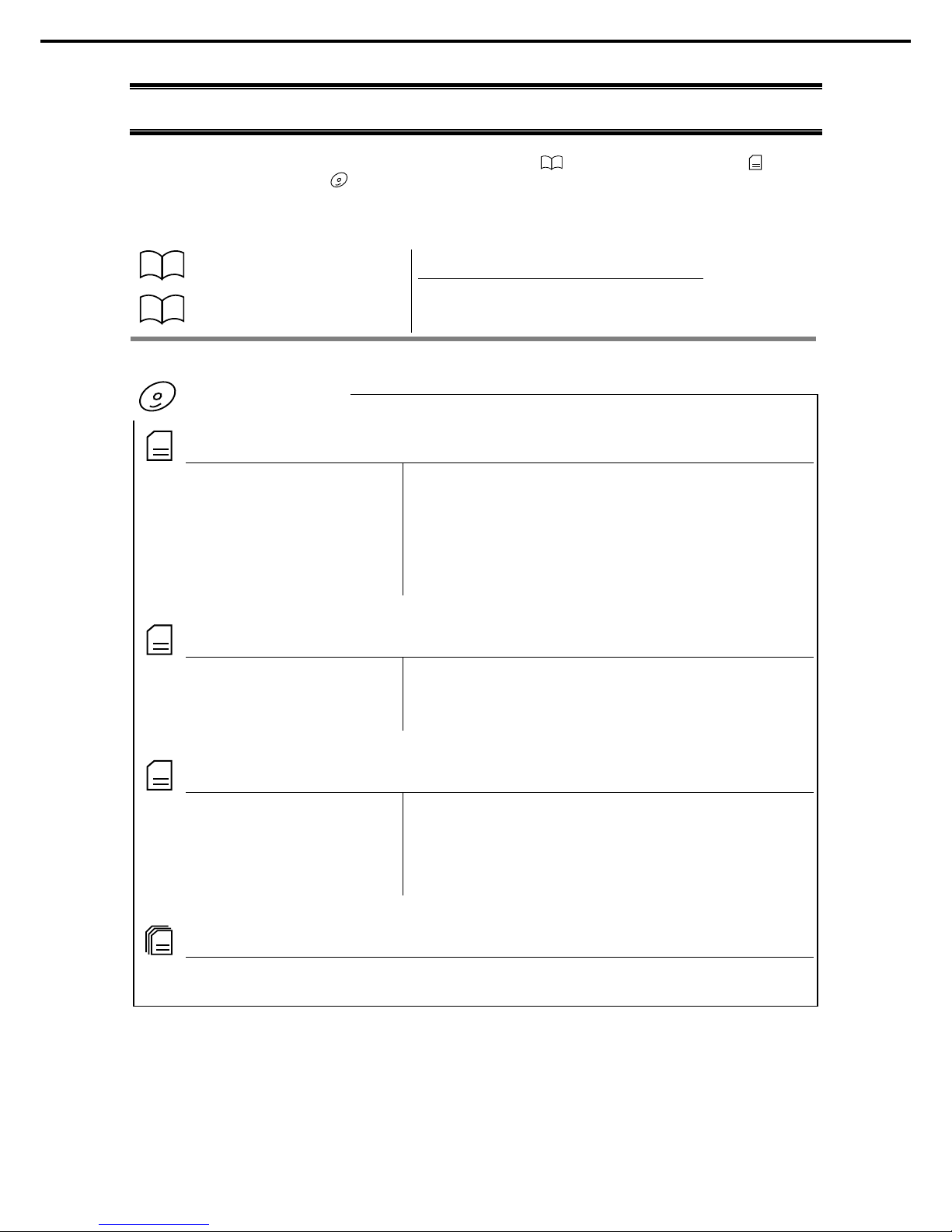
Docum ents for this product are provided as booklets ( ) and electronic manuals (
PDF
) in t he
EXPRESSBUILDER DVD (
).
Safety Precautions and
Regulatory Notices
Describes points of caution to ensure the safe use of this server.
Read these cautions before using this server.
Getting Started
Describes how to use this server, from unpacking to operations.
See this guide first and read the outline of this product.
PDF
User’s Guide
Chapter 1: General Descr iption Overviews, names, and functions of the server’s parts
Chapter 2: Preparations Installation of additional
options, connection of peripheral devices,
and suitable location for this server
Chapter 3: Setup System BIOS configurations and summary of EXPRESSBUILDER
Chapter 4: Appendix Specifications and other information
PDF
Installation Guide (Windows)
Chapter 1: Installing Windows Installation of Windows and drivers, and precautions for installation
Chapter 2: Installing Bundled
Software
Installation of NEC ESMPRO, Universal RAID Utility
, and other
bundled software
PDF
Maintenance Guide
Chapter 1: Maintenance Server maintenance and troubleshooting
Chapter 2: Useful Features The detail of system BIOS settings, RAID Configuration Utility, and
EXPRESSBUILDER
Chapter 3: Appendix Error messages and Windows Event Logs
PDF
Other documents
The detail of NEC ESMPRO, Universal RAID Utility, and other features.
EXPRESSBUILDER
Page 3

Contents
Express5800/R120f-1E User’s Guide
3
Contents
Docum ents for This Product ............................................................................................................................ 2
Contents ........................................................................................................................................................ 3
Notations Used in This Document ................................................................................................................... 6
Signs and symbols for safety .................................................................................................................. 6
Notations used in the text ....................................................................................................................... 7
Optical disk drive .................................................................................................................................... 7
Hard disk drive ....................................................................................................................................... 7
Removable media .................................................................................................................................. 7
Abbreviations of Operating Systems (Windows) ...................................................................................... 8
POST ................................................................................................................................................... 8
BMC ................................................................................................................................................... 8
Trademarks .................................................................................................................................................... 9
License Agreement Notice .............................................................................................................................10
Warnings and Additions to This Document......................................................................................................13
Latest editions .......................................................................................................................................13
Safety notes ..........................................................................................................................................14
Handling precautions (for proper operations) ..........................................................................................15
Handling precautions (for anti-static measures) ......................................................................................16
Chapter 1 General Description ....................................................................................................................18
1.
Introduction ...........................................................................................................................................19
2.
Accessories ..........................................................................................................................................20
3.
Features ...............................................................................................................................................21
3.1
Firmware and Software Version Management ..............................................................................24
4.
Names and Functions of Parts ...............................................................................................................25
4.1
Front View (With Front Bezel) .....................................................................................................25
4.2
Front View (Without Front Bezel) .................................................................................................26
4.3
Rear View ..................................................................................................................................27
4.4
External View .............................................................................................................................29
4.5
Internal View ..............................................................................................................................30
4.6
Motherboard ...............................................................................................................................31
4.7
Status Indicators .........................................................................................................................33
4.7.1 POWER LED ( ) .........................................................................................................33
4.7.2 STATUS LED 1, 2 ( )..................................................................................................33
4.7.3 LINK/ACT LED ( 1, 2, 3, 4) ........................................................................35
4.7.4 Optical Disk Drive Access LED ......................................................................................35
4.7.5 UID LED (ID).................................................................................................................35
4.7.6 Power Capping LED ......................................................................................................35
4.7.7 LED on a hard disk drive ...............................................................................................36
4.7.8 LEDs for LAN connectors ..............................................................................................37
4.7.9 AC POWER LED on power unit .....................................................................................39
Page 4

Contents
Express5800/R120f-1E User’s Guide
4
Chapter 2 Preparations ...............................................................................................................................40
1.
Installing Internal Options ......................................................................................................................41
1.1
Safety Precautions .....................................................................................................................41
1.2
Anti-static Measures ...................................................................................................................42
1.3
Overview of Installati on and Removal ..........................................................................................43
1.4
Identifying Server (UID Switch) ...................................................................................................45
1.5
Removing Front Bezel ................................................................................................................46
1.6
Removing Top Cover ..................................................................................................................47
1.7
TPM Kit ......................................................................................................................................48
1.7.1 Installation ....................................................................................................................48
1.8
Processor (CPU) ........................................................................................................................49
1.8.1 Maxim um number of processo r cores supported by this server .......................................49
1.8.2 Installation ....................................................................................................................50
1.8.3 Replacem ent / Removal ................................................................................................55
1.9
DIMM .........................................................................................................................................56
1.9.1 Maximum supported memory size .................................................................................56
1.9.2 Memory Clock ...............................................................................................................57
1.9.3 Memory RAS Feature ....................................................................................................58
1.9.4 DIMM installation order ..................................................................................................59
1.9.5 Installation ....................................................................................................................60
1.9.6 Removal / Replacement ................................................................................................61
1.9.7 Using Memory RAS Feature ..........................................................................................61
1.10
Flash Backup Unit for RAID Controller .........................................................................................69
1.10.1 Handling precautions .....................................................................................................69
1.10.2 Installing N8103-181 Flash Backup Unit .........................................................................69
1.10.3 Removal .......................................................................................................................72
1.10.4 Installing FBU for N8103-179 .........................................................................................73
1.10.5 Rem oving FBU..............................................................................................................74
1.11
LOM Card ..................................................................................................................................75
1.11.1 Installation ....................................................................................................................75
1.11.2 Rem oval .......................................................................................................................77
1.12
PCI Card ....................................................................................................................................78
1.12.1 Notes ............................................................................................................................78
1.12.2 Supported PCI cards and available slots ........................................................................79
1.12.3 Installation ....................................................................................................................85
1.12.4 Rem oval .......................................................................................................................86
1.12.5 Installing RAID controller ...............................................................................................87
1.13
Optical Disk Drive .......................................................................................................................89
1.13.1 Installation ....................................................................................................................89
1.13.2 Rem oval .......................................................................................................................90
1.14
Use of Internal Hard Disk Drives in the RAID System ...................................................................91
1.14.1 Connecting cables .........................................................................................................91
1.14.2 Notes on building RAID system .....................................................................................92
1.15
Installing Top Cover ....................................................................................................................93
1.16
Hard Disk Drive ..........................................................................................................................94
1.16.1 Installation ....................................................................................................................95
1.16.2 Rem oval .......................................................................................................................96
1.16.3 Replaci ng a hard disk drive in the RAID system (Auto Rebuild) .......................................97
1.17
Power Supply Unit ......................................................................................................................98
1.17.1 Cold redundant feature ..................................................................................................98
1.17.2 Installation ....................................................................................................................99
1.17.3 Replaci ng a failed power supply unit ............................................................................ 100
1.18
Installing Front Bezel ................................................................................................................ 101
Page 5

Contents
Express5800/R120f-1E User’s Guide
5
2.
Installation and Connection .................................................................................................................. 102
2.1
Installation ................................................................................................................................ 102
2.1.1 Installing Rack............................................................................................................. 102
2.1.2 Installing the server to the rack or removi ng i t from the rack .......................................... 104
2.2
Connection ............................................................................................................................... 109
2.2.1 Connecting to Uninterruptible Power Supply (UPS) ...................................................... 111
Chapter 3 Setup........................................................................................................................................ 112
1.
Turning on the Server .......................................................................................................................... 113
1.1
POST ....................................................................................................................................... 114
1.1.1 POST sequence .......................................................................................................... 114
1.1.2 POST error messages ................................................................................................. 115
2.
BIOS Setup Utility (SETUP) ................................................................................................................. 116
2.1
Overview .................................................................................................................................. 116
2.2
Starting SETUP ........................................................................................................................ 116
2.3
Usage of SETUP ...................................................................................................................... 117
2.4
Cases that Require Changes .................................................................................................... 11 9
3.
EXPRESSSCOPE Engine 3 ................................................................................................................ 121
3.1
Overview .................................................................................................................................. 121
3.2
EXPRESSSCOPE Engine 3 Network Configuration ................................................................... 122
4.
EXPRESSBUILDER ............................................................................................................................ 124
4.1
Features of EXPRESSBUILDER ............................................................................................... 124
4.2
Usage of EXPRESSBUILDER ................................................................................................... 124
5.
Installing Software ............................................................................................................................... 125
6.
Turning Off the Server ......................................................................................................................... 126
Chapter 4 Appendix .................................................................................................................................. 127
1.
Specifications ...................................................................................................................................... 128
2.
Interrupt Lines ..................................................................................................................................... 130
3.
Glossary ............................................................................................................................................. 131
Page 6
Notations Used in This Document
Express5800/R120f-1E User’s Guide
6
Notations Used in This Document
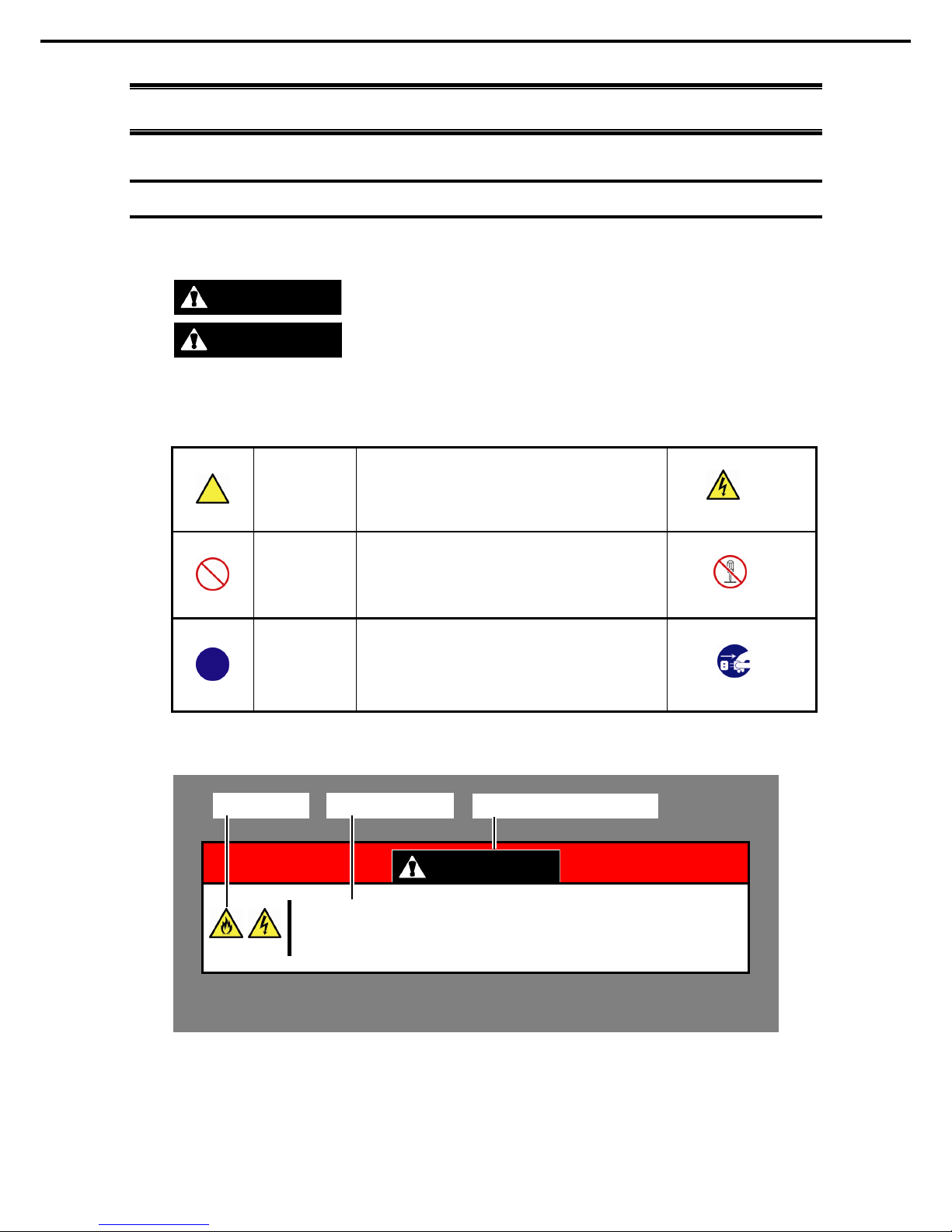
Signs and symbols for safety
WARNING and CAUTION are used in this guide as following m eaning.
WARNING
Indicates there is a risk of death or serious personal in jury
CAUTION
Indicates there is a risk of burns, other personal injur y, or property damage
Precautions and notices against hazards are presented with one of the following three symbols. The individual
symbols are defined as follows:
Attention
This symbol indicates the presence of a hazard if
the instruction is ignored.
An image in the symbol illustrates the hazard type.
Prohibited
Action
T
his symbol indicates prohibited actions. An image
in the symbol ill ustrates a particular prohibited
action.
Mandatory
Action
This symbol indicates mandatory actions. An
image in the symbol illustrates a mandatory action
to avoid a particular hazard.
(Example in this guide)
WARNING
Use only the specified outlet
Use a grounded outlet with the specified voltage. Use of an improper power source
may caus e a fir e or a power leak.
(Electric shock risk)
(Do not disassemble)
(Example)
(Example)
(Example)
(Disconnect a plug)
Symbol to draw
attention
Description of a warni ng
Term indicati ng a degree of danger
Page 7

Notations Used in This Document
Express5800/R120f-1E User’s Guide
7
Notations used in the text
In addition to safety-related symbols urging caution, three other types of notations are used in this document.
These notations have the following meanings.
Important Indicates critical items that must be followed when handling hardware or operating software.
If the procedures described are not followed,
server failure, data loss, and other serious
malfunctions could occur.
Note Indicates items that must be confirm ed when handling hardware or operating software.
Tips Indicates inform ation that is helpful to keep i n mind when using this server.
Optical disk drive
This server is equipped with one of the foll owing drives. These drives are referred to as optical disk dr ive (ODD)
in this document.
• DVD-ROM drive
• DVD Super MULTI drive
Hard disk drive
Unless otherwise stated, hard disk drive described in this document refer to both of the following.
• Hard disk drive (HDD)
• Solid state drive (SSD)
Removable media
Unless otherwise stated, removable media descr ibed in this docum ent refer to both of the following.
• USB flash drive
• Flash FDD
Page 8

Notations Used in This Document
Express5800/R120f-1E User’s Guide
8
Abbreviations of Operating Systems (Windows)
Windows Operating Systems are referred to as follows.
See Chapter 1 (1.2 Supported Windows OS) in Installation Guide (Windows) for detailed information.
Notations in this document Official names of Windows
Windows Server 2012 R2
Windows Server 2012 R2 Standard
Windows Server 2012 R2 Datacenter
Windows Server 2012
Windows Server 2012 Standard
Windows Server 2012 Datacenter
Windows Server 2008 R2
Windows Server 2008 R2 Standard
Windows Server 2008 R2 Enterprise
Windows Server 2008 *
Windows Server 2008 Standard
Windows Server 2008 Enterprise
* Includes 32-bit Edition unless otherwise stated.
POST
POST described in this document refers to the following.
• Power On Self-Test
BMC
BMC descr ibed in this document refers to the following.
• Baseboard Management Controller
Page 9

Trademarks
Express5800/R120f-1E User’s Guide
9
Trademarks
EXPRESSSCOPE and ExpressUpdate are registered trad emark of NEC Corporation.
Microsoft, W indows, W indows Server , W indows Vista, and MS-DOS are registered trademarks or tr ademar ks of Microsoft Corporation
in the United States and other countries. Intel, Pentium, and Xeon are register ed trademarks of Intel Corporation of the United States .
AT is a registered trademark of International Business Machines Corporation of th e United States and other count ries. Adaptec, its
logo, and SCSI Select are registered trademarks or trademarks of Adaptec, Inc. of the Unit ed States. Avago, LSI, and the LSI &
Design logo are trademarks or registered trademarks of Avago T echnologies in the U nited States and/or other c ountries. A dobe, the
Adobe logo, and Acrobat are trademarks of Adobe Systems Incorporated. DLT and DLTtape are trademarks of Q uantum Corporation
of the Un ited States. P CI Express is a trademark of Peri pheral Component Interconnect Special Interest Group.
All other product, brand, or trade names us ed in this publication are the tr ademar ks or registered trademarks of their respective
trademark owners.
Page 10

License Agreement Notice
Express5800/R120f-1E User’s Guide
10
License Agreement Notice
Open source software of following license is included in the part of this product (system BIOS).
• EDK from Tianocore.org
• UEFI Network Stack 2
• Crypto package using WPA Supplicant
Open source software of foll owing license is included in the part of this product (Off-line Tools).
• EDK from Tianocore.org
EDK FROM TIANOCORE.ORG
BSD License from Intel
Copyright (c) 2012, Intel Corporation
All rights reserved.
Redistribution and use in so urce and binary forms, with or without modification, are permitted provided that the
following conditions are met:
• Redistributions of source code must retain the above copyright notice, this list of conditions and the following
disclaimer.
• Redistributions in binary form must reproduce the above copyright notice, this list of conditions and the
following disclaimer in the documentation and/or other materials provided with the distribution.
• Neither the name of the Intel Corporation nor the nam es of its contributors may be used to endorse or
promote products derived from this software without specific prior written permission.
THIS SOFTWARE IS PROVIDED BY THE COPYRIGHT HOLDERS AND CONTRIBUTORS "AS IS" AND ANY
EXPRESS OR IMPLIED WARRANTIES, INCLUDING, BUT NOT LIMITED TO, THE IMPLIED WARRANTIES OF
MERCHANTABILITY AND FITNESS FOR A PARTICULAR PURPOSE ARE DISCLAIMED. IN NO EVENT
SHALL THE COPYRIGHT OWNER OR CONTRIBUTORS BE LIABLE FOR ANY DIRECT, INDIRECT,
INCIDENTAL, SPECIAL, EXEMPLARY, OR CONSEQUENTIAL DAMAGES (INCLUDING, BUT NOT LIMITED
TO, PROCUREMENT OF SUBSTITUTE GOODS OR SERVICES; LOSS OF USE, DATA, OR PROFITS; OR
BUSINESS INTERRUPTION) HOWEVER CAUSED AND ON ANY THEORY OF LIABILITY, WHETHER IN
CONTRACT, STRICT LIABILITY, OR TORT (INCLUDING NEGLIGENCE OR OTHERWISE) ARISING IN ANY
WAY OUT OF THE USE OF THIS SOFTWARE, EVEN IF ADVISED OF THE POSSIBILITY OF SUCH DAMAGE.
Copyright (c) 2004 - 2007, Intel Corporation
All rights reserved. This program and the accompanying materials are licensed and made available under the
terms and conditions of the BSD License whi ch accompanies this distribution. The full text of the license may be
found at http://opensource.org/licenses/bsd-license.php
THE PROGRAM IS DISTRIBUTED UNDER THE BSD LICENSE ON AN "AS IS" BASIS, WITHOUT
WARRANTIES OR REPRESENTATIONS OF ANY KIND, EITHER EXPRESS OR IMPLIED.
Page 11

License Agreement Notice
Express5800/R120f-1E User’s Guide
11
UEFI NETWORK STACK 2
OpenSSL License
-------
Copyright (c) 1998-2011 The OpenSSL Project. All rights reserved.
Redistribution and use in source and binary forms, with or without modification, are permitted provided that the
following conditions are met:
1. Redistributions of source code must retain the above copyright notice, this list of conditions and the
following disclaimer.
2. Redistributions in binary form must reproduce the above copyright notice, this list of conditions and the
following disclaimer in the documentation and/or other materials provided with the distribution.
3. All advertisi ng materials mentioning features or use of this software must display the following
acknowledgment:
"This product includes software developed by the OpenSSL Project for use in the OpenSSL Toolkit.
(http://www.openssl.org/
)"
4. The names "OpenSSL Toolkit" and "OpenSSL Project" must not be used to endorse or promote products
derived from this software without prior written permission. For written permissi on, please contact
openssl-core@openssl.org
.
5. Products derived from this software may not be called "OpenSSL" nor may "OpenSSL" appear in their
names without prior written permission of the OpenSSL Project.
6. Redistributions of any form whatsoever must retain the following acknowledgment:
"This product includes software developed by the OpenSSL Project for use in the OpenSSL Toolkit
(http://www.openssl.org/)"
THIS SOFTWARE IS PROVIDED BY THE OpenSSL PROJECT ``AS IS'' AND ANY EXPRESSED OR IMPLIED
WARRANTIES, INCLUDING, BUT NOT LIMITED TO, THE IMPLIED WARRANTIES OF MERCHANTABILITY
AND FITNESS FOR A PARTICULAR PURPOSE ARE DISCLAIMED. IN NO EVENT SHALL THE OpenSSL
PROJECT OR ITS CONTRIBUTORS BE LIABLE FOR ANY DIRECT, INDIRECT, INCIDENTAL, SPECIAL,
EXEMPLARY, OR CONSEQUENTIAL DAMAGES (INCLUDING, BUT NOT LIMITED TO, PROCUREMENT OF
SUBSTITUTE GOODS OR SERVICES; LOSS OF USE, DATA, OR PROFITS; OR BUSINESS INTERRUPTION)
HOWEVER CAUSED AND ON ANY THEORY OF LIABILITY, WHETHER IN CONTRACT, STRICT LIABILITY,
OR TORT (INCLUDING NEGLIGENCE OR OTHERWISE) ARISING IN ANY WAY OUT OF THE USE OF THIS
SOFTWARE, EVEN IF ADVISED OF THE POSSIBILITY OF SUCH DAMAGE.
This product includes cryptographic software written by Eric Young (eay@cryptsoft.com
).
This product includes software written by Tim Hudson (tjh@cryptsoft.com).
Page 12

License Agreement Notice
Express5800/R120f-1E User’s Guide
12
CRYPTO PACKAGE USING WPA SUPPLICANT
WPA Supplicant
-------
Copyright (c) 2003-2012, Jouni Malinen <j@w1.fi> and contributors
All Rights Reserved.
This program is licensed under the BSD license (the one with advertisement clause removed).
If you are su bmitting changes to the project, please see CONTRIBUTIONS file for more instructi ons.
License
-------
This software may be distributed, used, and modified under the terms of
BSD li cense:
Redistribution and use in source and binary forms, with or without modification, are permitted provided that the
following conditions are met:
1. Redistributions of source code must retain the above copyright notice, this list of conditions and the
following disclaimer.
2. Redistributions in binary form must reproduce the above copyright notice, this list of conditions and the
following disclaim er in the documentation and/or other materials provided with the di stribution.
3. Neither the name(s) of the above-listed copyright holder(s) nor the names of its contributors may be used to
endorse or promote products derived from this software without specific prior written permission.
THIS SOFTWARE IS PROVIDED BY THE COPYRIGHT HOLDERS AND CONTRIBUTORS "AS IS" AND ANY
EXPRESS OR IMPLIED WARRANTIES, INCLUDING, BUT NOT LIMITED TO, THE IMPLIED WARRANTIES OF
MERCHANTABILITY AND FITNESS FOR A PARTICULAR PURPOSE ARE DISCLAIMED. IN NO EVENT
SHALL THE COPYRIGHT OWNER OR CONTRIBUTORS BE LIABLE FOR ANY DIRECT, INDIRECT,
INCIDENTAL, SPECIAL, EXEMPLARY, OR CONSEQUENTIAL DAMAGES (INCLUDING, BUT NOT LIMITED
TO, PROCUREMENT OF SUBSTITUTE GOODS OR SERVICES; LOSS OF USE, DATA, OR PROFITS; OR
BUSINESS INTERRUPTION) HOWEVER CAUSED AND ON ANY THEORY OF LIABILITY, WHETHER IN
CONTRACT, STRICT LIABILITY, OR TORT (INCLUDING NEGLIGENCE OR OTHERWISE) ARISING IN ANY
WAY OUT OF THE USE OF THIS SOFTWARE, EVEN IF ADVISED OF THE POSSIBILITY OF SUCH DAMAGE.
Page 13

Warnings and Additions to This Document
Express5800/R120f-1E User’s Guide
13
Warnings and Additions to This Document
1. Unauthorized reproduction of the contents of this document, in part or in its entirety, is prohibited.
2. This document is subject to change at any time without notice.
3. Do not make copies or alter the document content without permission from NEC Corporation.
4. If you have any concerns, or discover errors or omissions in this document, contact your sales
representative.
5. Regardless of article 4, NEC Corporation assumes no responsibility for effects resulting from your
operations.
6. The sample values used in this document are not actual values.
Keep this document for future use.
Latest editions
This document was cr eated based on the information available at the tim e of its creation. The screen images,
messages, and procedures are subject to change without notice. Substitute as appropriate when content has
been modified.
The most recent version of User’s Guide, as well as other related documents, is also available for download
from the following website.
http://www.nec.com/
Page 14
Warnings and Additions to This Document
Express5800/R120f-1E User’s Guide
14
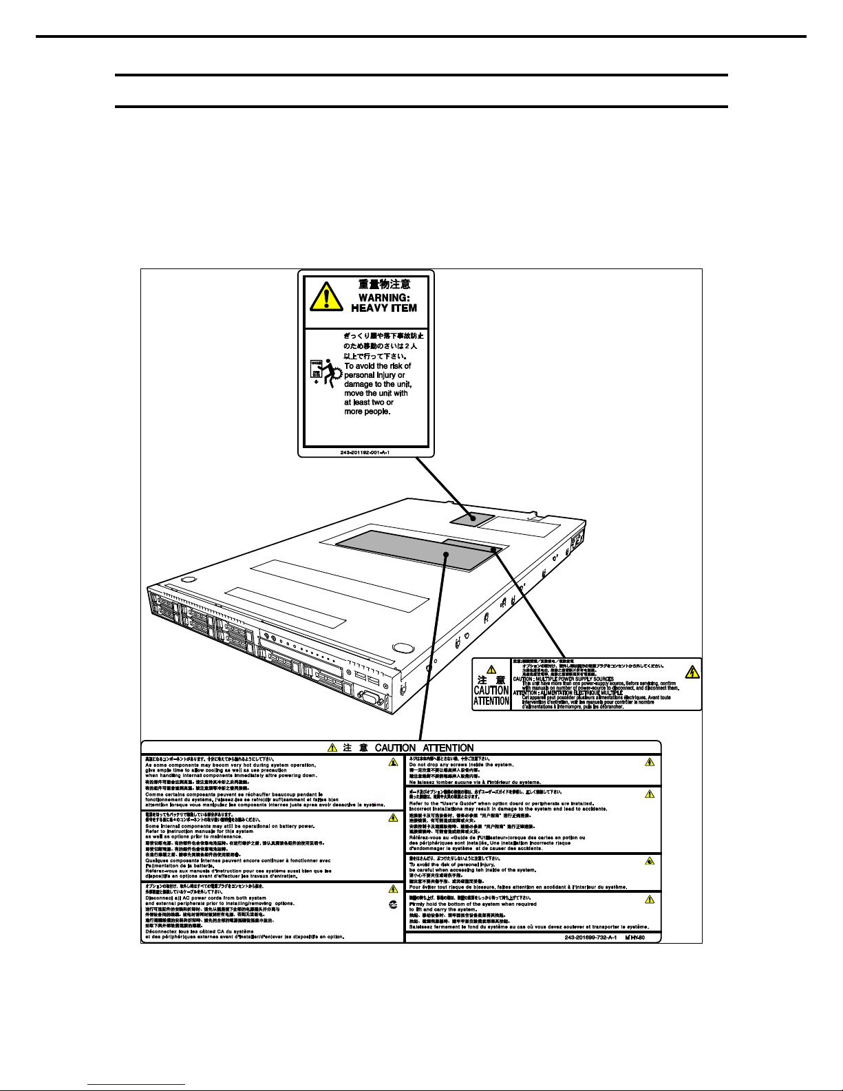
Safety notes
To use this server safely, read thoroughly Safety Precautions and Regulatory Notices that comes with your
server.
Warning labels are attached on or near the components with potential hazards. These labels are attached or
printed on the components.
Do not remove or black out these labels and keep th em clean. If no labels are attached or printed on the server,
contact your sales representative.
Page 15

Warnings and Additions to This Document
Express5800/R120f-1E User’s Guide
15
Handling precautions (for proper operations)
Be sure to observe the following precautions for the proper functioning of the server. Ignoring the precauti ons
may cause server malfunction or failure.
• Do not use any cell phone or PHS and switch off them near the server. Electric waves from such
devices can cause server to malfunction.
• Install the server in an appropriate place. For details about the installation location, see Chapter 2
Preparations (2. Installation and Connection).
• Before connecting/removing cables to/from peripheral devices, make sure that the server is off and
unplug the power cord, if they are non plug-and-play devices.
• Connect the provided power cord to a 100/200 VAC outlet.
• Make sure that the access LED on the server is off before turning off the power or ejecting an optical
disk.
• Wait for at least 30 seconds before connecting power cord to power outlet after disconnecting it.
• If any Uninterruptible Power Supply (UPS) unit is connected, set it to wait for at least 30 seconds
before turning on the server after power off.
• Do not press the POWER switch to turn on the server before the STATUS LED 2 (amber) is unlit.
• Wait for at least 30 seconds before turning on the server after turning off the server.
• Turn off the server and unplug the power cord before moving it.
• Regularly clean the server to prevent various types of failure. See Chapter 1 Maintenance (2. Daily
Maintenance) in "Maintenance Guide" for details.
• Momentary voltage drop may occur due to lightning strike. To prevent this, use of UPS is
recommended.
• Any copy-protected CD that does not conform to standards is not supported.
• In the following cases, check and adjust the system clock before operation.
− After transportation
− After storage
− After the server is used following a period of disuse, in which storage conditions di d not conform to those
that guarantee server operations (temperature: 10 to 40°C; humidity: 20% to 80%).
• Check the system clock approximately once per month. Use of a time server (NTP server) is
recommended if high accuracy timing is required by the system .
• Observe the storage conditions (Temperature:
−10°C to 55°C, Humidity: 20% to 80%, No
condensation of moisture) to store the server.
• Do not power off or reset the server, nor disconnect the power cord before POST completes.
• If this server, internal optional devices, and media set for the backup devices (tape cartridges) are
moved from a cold place to a warm place in a short time, condensation will occur and cause
malfunctions and failures when these are used in such state. To protect important stored data and
property, make sure to wait for a sufficient period to use the server and components in the operating
environment.
Refer ence: Time effective at avoi ding condensation in winter (more than 10°C differences between the
room temperature and atmospheric temperature)
Disk devices: Approximately 2 to 3 hours Tape media: Approximately 1 day
• For optional devices, we recommend you use our NEC products. Even if they are successfully
installed or connected, installation of unsupported devices can cause the server to malfunction or
even failure. You will be charged to repair failure or damage caused by use of such products even
within warranty period.
Page 16

Warnings and Additions to This Document
Express5800/R120f-1E User’s Guide
16
Handling precautions (for anti-static measures)
The server contains static-sensitive components. Take the measu res below to avoid failures caused by static
electricity when installing or removing any optional devices.
• Wearing Anti-static Wrist Strap or Anti-static Gloves
Wear a wrist strap on your wrist and connect the wire to the chassis. If there is no wrist strap, touch an
unpainted metal surface of the chassis connected to the ground to discharge static electricity from your
body before touching the component. Touch the metal part occasionally to discharge the static electricity
while working on the component.
• Checking the Workplace
− Work on an anti-static floor or concrete floor.
− If you work on a place where st atic electricity is likely to be generat ed (such as carpet), be sure to
provide anti-static protection.
• Using the Work Table
Place the server on a mat with Electrostatic Discharge (ESD) protection.
• Clothing
− Do not wear wool or synthetic clothes.
− Wear anti-static shoes.
− Remove a ring, bracelet, wrist watch, and any kind of metal accessories.
• Handling of Components
− Keep the component in an anti-static bag until you install it to the server.
− Hold the component by the edges to avoid touching any terminals or mounting parts.
− Place the component in an anti-static bag when storing or moving them.
• Handling of Cables
When connecti ng a ca ble (a long LAN cable), static electricity may also be charged due to friction against
the floor. Connecting the charged cable with a device will cause dam age to the devices in the system. It is
recommended to use a product su ch as electrostatic discharge ki t to eliminate the static charge before
connecting the cable.
• Installing and Uninstalling the Optional Device
− To avoid electric hazard and malfunction, be sure to turn off the power switch of the server and unplug
the power cord from the outlet before installing or uninstalling any optional device.
− If the device is a hot-plug devi ce, you do not need to turn off the power switch.
− The device contains static-sensitive electronic components. When installing or uninstalling the optional
device, wear an anti-static wrist strap on your wrist to avoid a failure caused by the static electricity. To
use the strap, connect the wire to the chassis.
Page 17
Warnings and Additions to This Document
Express5800/R120f-1E User’s Guide
17
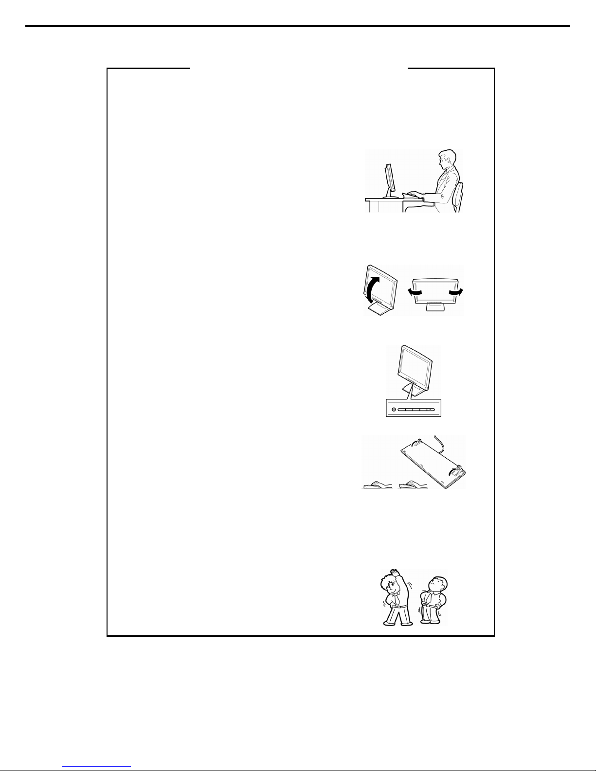
Using a c omputer extens ively may affect dif ferent parts of your body. H ere are tips you should follow while workin g on
a computer to minimize strain on your body.
Keep proper posture
The basic body position f or using a computer is sitting straight with
your hands on the keyboar d parallel with the floor, and your eyes
directed slightly downward toward the moni tor. W ith the pr oper
postu re described above, no unnecessary strain is applied on any
part of your body, in other words when your muscles ar e most
relaxed.
W orking on the computer with bad posture suc h as hunching over or
being too close to the monitor could caus e fatigue or deteriorated
eyesight.
Adjust the angle of your display
Most display units are designed for adjustment of the horizont al and
vertical angles. This adjustment is important to prevent the screen
from reflecting bright lights and to make the display contents easy to
see. Working without adjusting the display to a comfort able angle
makes it difficult for you to maintain a pr oper posture and you will
get tired easily. Adjust the viewing angle before use.
Adjust the brightness and contrast of the display
Display screens have functions to contr ol brightness and c ontrast.
The most suitable brightness/contrast depends on age, individuals,
and envir onment, so adjust it to s uit your pr eferences. A too bright
or too dark display is bad f or your eyes.
Adjust the angle of keyboard
Some keyboards are ergonomic ally designed, which allow the angle
to be adjusted. Adjusting th e angle of the keyboard is effect ive to
reduce tension on your shoulders, arms, and fingers.
Clean your equipment
Keeping your equipment clean is imp ortant not only for the appearance but also for function al an d s af ety reas ons. A
dusty monitor makes it difficult to s ee the display contents, s o clean it regularly.
Take rest breaks
When you feel tired, take a break
. Light exercise is also
recommended.
Tips for your health and safety
Page 18

Express5800/R120f-1E User’s Guide
18
NEC Express5800 Series
Express5800/R120f-1E
General Description
This chapter introduces the features of this server and the name of each part.
1. Introduction
2. Accessories
Describes the accessories of the server.
3. Features
Describes the features of the server and server management.
4. Names and Functions of Parts
Describes the name of each part cont ained in this server.
1
1
Page 19

1. Introduction
Express5800/R120f-1E User’s Guide
19
Chapter 1 General Description
1.
Introduction
Thank you for purchasing this NEC Express5800 Series product.
This high performance server is powered by the latest microprocessor "Intel
®
Xeon® processor".
NEC’s latest technology and architectures realize high-power and high-speed operation that cannot be matched
by existing servers.
The server is designed with consideration of not only reliability but also expandability, which enables you to use
it as a network server.
Read this document before using the server thoroughly to fully understand handling of Express5800 Series
Server and appreciate its functions to the maximum extent.
Page 20

2. Accessories
Express5800/R120f-1E User’s Guide
20
Chapter 1 General Description
2.
Accessories
The carton box contains various accessories which are required for setup or maintenance. Make sure you
have them all for future use.
• Front Bezel
• Bezel Lock Key (attached to Front Bezel)
• Slide Rails
• EXPRESSBUILDER
*1
• Safety Precautions and Regulatory Notices
• Getting Started
*1 Instruction manuals are stored in EXPRESSBUILDER. Adobe Reader is needed to read the m anuals.
Make su re you have all accessories and inspect them. If an accessory is missing or damaged, contact your
sales representative.
Important
The chassis serial number plate and maintenance label i s located on the
server. If the serial number does not match the number on the warranty, you
may not be guaranteed against failure even within the warr anty period.
Contact your sales representative if they do not match.
Page 21

3. Features
Express5800/R120f-1E User’s Guide
21
Chapter 1 General Description
3.
Features
The server has the following feat ures:
High performance
• Intel
®
Xeon® processor
– N8101-768F : E5-2603 v3 (1.60GHz 6Core)
– N8101-770F : E5-2620 v3 (2.40GHz 6Core)
– N8101-934F : E5-2630 v3 (2.40GHz 8Core)
– N8101-935F : E5-2630L v3 (1.80GHz 8Core)
– N8101-773F : E5-2640 v3 (2.60GHz 8Core)
– N8101-936F : E5-2650 v3 (2.30GHz 10Core)
– N8101-775F : E5-2650L v3 (1.80GHz 12Core)
– N8101-776F : E5-2660 v3 (2.60GHz 10Core)
• Turbo Boost Technology feature *1
• Hyper Threading Technology feature *1
• High-speed memory access (DDR4 1600/1866/2133 supported) *2
• High-speed disk access (SATA 6Gbps / SAS 12GB/s supported)
• High-speed 10GBASE-SFP+ / 10GBASE-T / 1000BASE-T/100BASE-TX / 10BASE-T interface
(10Gbps / 1Gbps / 100Mbps / 10Mbps supported)
High reliability
• Processor throttle-ring feature
• Memory monitori ng feature (error correct ion/error detection)
• Memory degeneracy feature (logical isolation of a failed device)
• Memory x4 SDDC feature
• Memory mirroring, memory LockStep (x8 SDDC), memory sparing features
• Memory throttle-ring feature
• Bus parity error detection
• Temperature detection
• Error detect ion
• Internal fan monitoring feature
• Internal voltage monitoring feature
• Power redundant feature (hot swapping supported)
• RAID system (Disk Array) (An option card is required.)
• Auto rebuild feature (hot swapping supported)
• BIOS password feature
• The security lock that comes with Front Bezel
• Redundant fan
• HDD (hot swapping supported)
Page 22

3. Features
Express5800/R120f-1E User’s Guide
22
Chapter 1 General Description
Management Utilities
• NEC ESMPRO
• ExpressUpdate
• Remote controlling feature (EXPRESSSCOPE Engine 3)
• RAID system management utility (Universal RAID Utility)
• Hard disk drive monitoring
• Power supply monitoring
Power saving and noiseless design
• Selection of power unit appropriate to environment, work load, and configuration
• Power consumption monitoring feature
• Power control feature
• 80 PLUS
®
Platinum / Titanium certified high efficiency power supply *4
• Fan control appropriate to environment, work load, and configuration
• Silent sound design
• Enhanced Intel SpeedStep
®
Technology supported
• Cold redundant feature
Expandability
• PCI Express 3.0 (x8 lanes) : 1 slot (Full height) *5, 6
• PCI Express 3.0 (x8 lanes): 1 slot (Low profile) *6
• PCI Express 3.0 (x8 lanes): 1 slot (dedicated to RAID controller)
• LOM card slot (x8 lanes): 1 slot (dedicated to LOM card)
• Large capacity memory of up to 256 GB *3
• Can upgrade to multi-processor system with up to two processors
• Expansion Bay (for hard disk drives): 8 slots
• Optical disk drive bay provided as standard
• USB3.0 interface (Front: 2 ports, rear: 2 ports, internal: 1 port)
• USB2.0 interface (internal: 2 ports)
• Management LAN port (1 port)
• With optional LOM card, two to four ports can be added.
Ready to use
• No cable connection is required to install a hard disk drive and additional power supply unit (hot swap
supported).
• Slide rails for each installation
Many built-in Features
• Redundant power supply system supported (valid when optional power supply unit is installed)
• El Torito Bootable CD-RO M (no emulation mode) format supported
• Software power-off
• Remote power-on feature
• AC-Link feature
• Remote console feature
• Power switch mask
• Connector for display unit provided on front panel
• Baseboard Management Controller (BMC) conforming to IPMI v2.0
Page 23

3. Features
Express5800/R120f-1E User’s Guide
23
Chapter 1 General Description
Self-diagnosis
• Power On Self-Test (POST)
• Test and Diagnosis (T&D) utility
Easy setup
• EXPRESSBUILDER (setup utility)
• BIOS Setup utility (SETUP)
Maintenance features
• Off-line Tools
• Memory dump feature using DUMP Switch
• Feature to back up and restore BIOS/BMC settings using EXPRESSSCOPE Profile Key
*1: Unsupported on Xeon processor E5-2603 v3 embedded models.
*2: Processor core speed depends on processor type, number and type of DIMMs installed.
*3: In 2-CPU configuration. Up to 384 GB in 1-CPU configuration.
*4: Requires N8181-118F power unit. Power supply unit N8181-121F/122F is compliant to 80 Plus Platinum.
*5: Requires N8116-39 Riser Card (PCIe x8)
*6: Can be changed to PCI Express 3.0: 1 slot (x16 lanes) by using optional riser card.
Page 24

3. Features
Express5800/R120f-1E User’s Guide
24
Chapter 1 General Description
3.1
Firmware and Software Version Management
Use of NEC ESMPRO Manager and ExpressUpdate Agent allows you to manage versions of firmware and
software as well as update them by applying update packages.
This feature automatically updates modules without stopping the system just by specifying the updating
packages from NEC ESMPRO Manager.
Page 25
4. Names and Functions of Parts
Express5800/R120f-1E User’s Guide
25
Chapter 1 General Description
4.
Names and Functions of Parts
This section describes the names of the server parts.
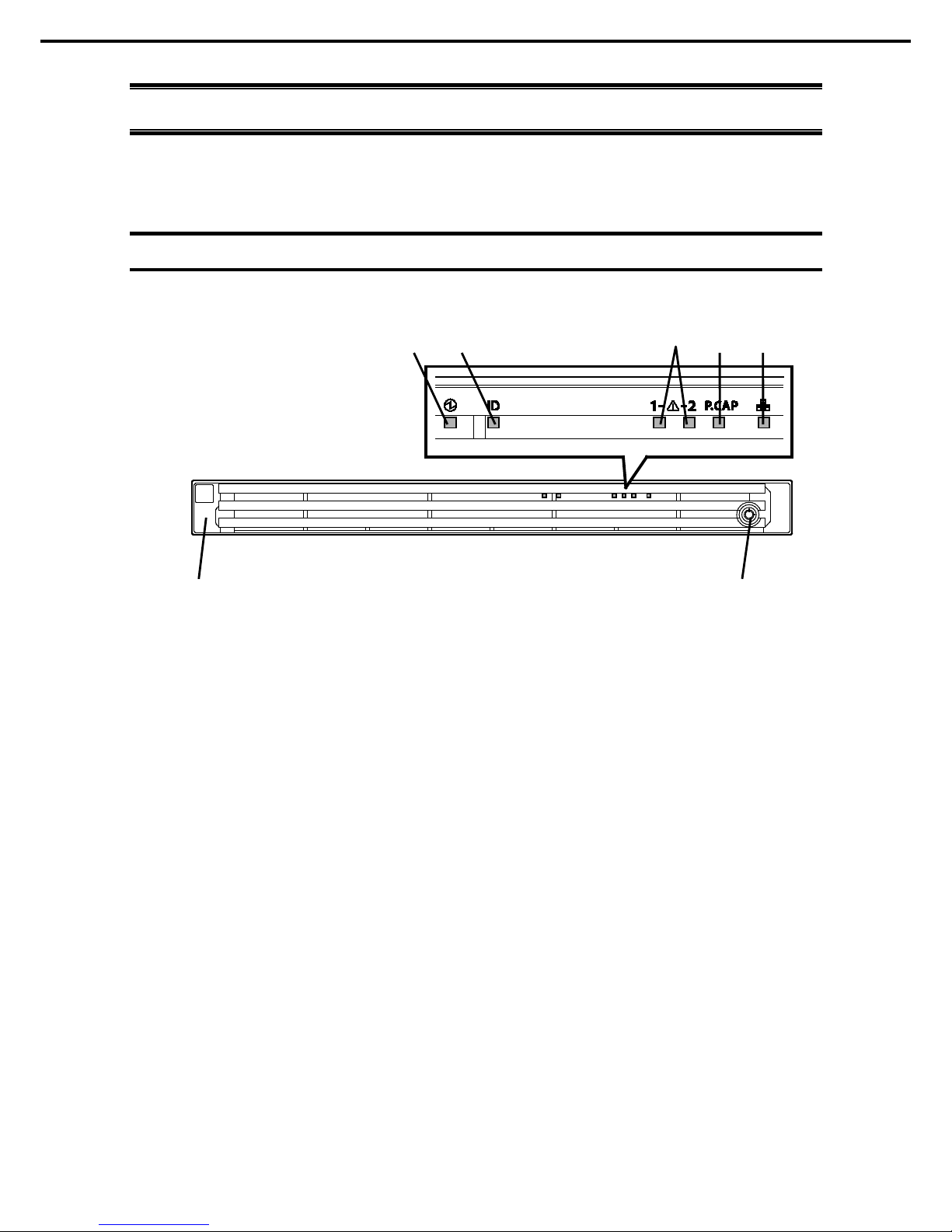
4.1
Front View (With Front Bezel)
(1) Front Bezel
A cover to protect the front of th e s er ver. This cover can be
locked with the provided Bezel Lock Key.
(2) Key Slot
A slot for Bezel Lock Key that is used to lock Front Bezel.
(3) LINK/ACT LED
LEDs f or showing the status of accessing the network.
(See page 35)
(4) Power Capping LED
An LED for showing the power capping stat us of th e s erver.
(See page 35)
(5) STAT US LED 1, 2
LEDs for showing the s erver status.
(See page 33)
(6) Unit ID (UI D) LED
An LED f or maintaining the server. This LED turns on when
UID Switch is pressed. Commands from the software als o
cause it t o turn on or f lash.
(See page 35)
(7) POWER LED
An LED for showing the power status of server.
(See page 33)
(1) (2)
(7) (6) (3) (4) (5)
Page 26
4. Names and Functions of Parts
Express5800/R120f-1E User’s Guide
26
Chapter 1 General Description
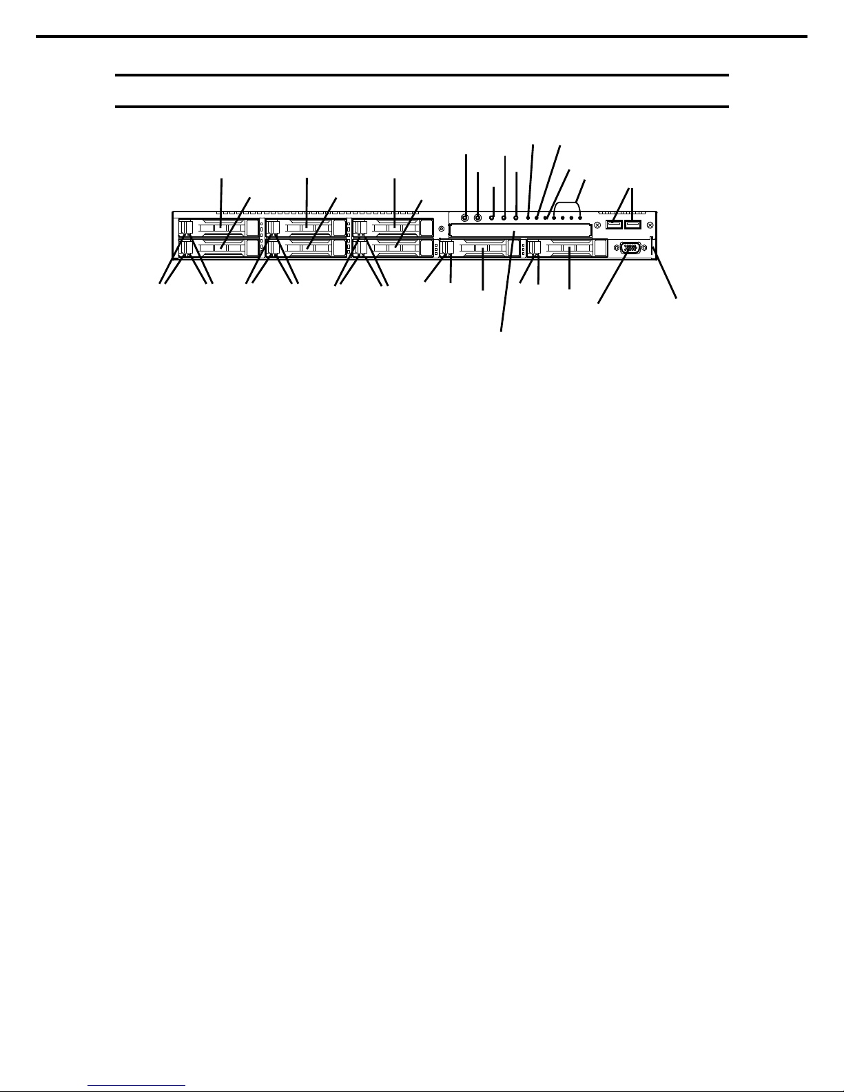
4.2
Front View (Without Front Bezel)
(8) 2.5-inch Hard Disk Drive Bay
Bays f or installing HDDS. The sequential numbers indicate
the corresponding slot numbers. All bays include Dummy
Trays as s tandar d.
(9) DISK Access LED
LEDs for showing the access of hard disk drives.
The LED is provided f or each hard disk drive.
(See page 36)
(10) DISK ST ATUS LED
LEDs f or showing the status of hard disk dr ive.
The LED is provided f or each hard disk drive.
(See page 36)
(11) POWER Switch/LED
A switch f or turning on/off the server. Press onc e to turn on
the server. POW ER LED lights when it is on. Press it again
to turn off the ser ver. H old d own the switch for four seconds
or more to forcibly turn off the server.
(See page 33)
(12) Unit ID (UID) Switch/LED
A switch for turning on/off UID LED.
Pressing the switch once turns on UID LED and pressing
again turns off the LED.
Commands from the software also c ause it to turn on or
flash .
(See page 35)
(13) RESET Switch
A switch for resetting the server.
(14) DUM P Switch (NM I)
A switch for collecting the memory dump.
(15) BMC RESET Switch
A switch f or resetting BMC of this s erver. Use the switch
only when there is a problem with EXPRESSSCOPE
Engine 3 (BMC).
To use this switch, press it at least five seconds.
(16) STATUS LED 1, 2
LEDs for showing the s erver status.
(See page 33)
(17) Power Capping LED
An LED for showing the power capping stat us of th e s erver.
(See page 35)
(18) LINK/ACT LED
LEDs for showing the access status of LAN.
(3)-1: LAN1 con nector
(3)-2: LAN2 conn ect or
(3)-3: LAN3 conn ect or
(3)-4: LAN4 conn ect or
LEDs f or LAN3 and LAN 4 are lit when optional LOM card
(N8104-154/156) is installed.
(19) USB Connectors (front)
Connec to rs for c onnecti ng USB interface devi ces.
(20) Pull-out Tab
A tab for showing the part number and serial number of th e
ser ver .
(21) Display Connector
A c onnector f or connecting a display. This connector
cannot be used with the display connector on rear panel at
the same time.
(22) Optical Disk Drive Bay
A bay for installing an optic al disk drive.
Either of the f ollowin g drive can be installed.
– DVD-ROM dri ve
– DVD SuperMULTI drive
(21)
(22)
(8)-1
(18)
(12)
See (3) to (5) on previous page.
(17)
(8)-0 (8)-2
(8)-3
(8)-4
(8)-5
(11)
(13)
(14)
(8)-6
(8)-7
(10)
(10) (9)
(9)
(10) (9)
(10)
(9)
(10) (9)
(15)
(16)-1
(16)-2
(19)
(20)
Page 27
4. Names and Functions of Parts
Express5800/R120f-1E User’s Guide
27
Chapter 1 General Description
4.3
Rear View
(11)
(3)
(7) (6)
(13)
(1)
(2)
(4)
(8)
(5)
(12)
(15)
(18)
(14)
(9)
(12)
(10)-2 (10)-1
(10)-3
(10)-4
(11)
(9)
(11)
(11)
(3)
(7) (6)
(13)
(1)
(2)
(4)
(8)
(5)
(12)
(15)
(18)
(14)
(9)
(12)
(9)
(10)-2
(10)-1
(11)
(11)
(7) (6)
(13)
(1)
(2)
(4)
(8)
(5)
(12)
(15)
(18)
(14)
(9)
(12)
(9)
(10)-2
(10)-1
(10)-3
(10)-4
Page 28

4. Names and Functions of Parts
Express5800/R120f-1E User’s Guide
28
Chapter 1 General Description
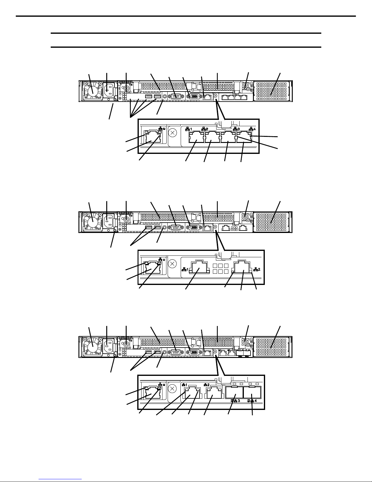
(1) Power Unit (Power supply slot 1)
A power supply f or supplying the DC power to the server.
(2) AC Inlet
A socket for connecting the power c ord.
(3) AC POWER LED
An LED for showing th e power supply status.
(See page 39)
(4) Cap Screw
A screw for fixing the top c over.
(5) Slot for Full-height PCI Card
A slot for installing a full-height PCI c ard.
Assigned PCI sl ot number is "1C".
(6) Slot for Low-profile PCI Card
A slot for installing a low-profile PCI c ard.
Assigned PCI sl ot number is "1D".
(7) Blank Cover (for power unit #2)
A cover f or protecting the bay of additional power supply.
(8) US B Connectors
Connec to rs for c onnecti ng USB interface devi ces.
(9) LINK/ACT LED *1
LEDs for showing the access status of LAN.
(See page 37)
(10) LAN Connectors *1
LAN connectors which supports
1000BASE-T/100BASE-T X/10BASE-T.
(10)-1: LAN 1 port conn ect or
(10)-2: LAN 2 port conn ect or
(10)-3: LAN 3 port conn ect or
(10)-4: LAN 4 port conn ector
If Shared BMC LAN feature is enabl ed in RO M Utility,
LAN1 connector c an als o be used as the management
LAN port. Sharing port is not recommended from the point
of p erf or manc e and s ec urity.
(11) SPEED LED *1
LEDs for showing the transfer spe ed of LAN ports.
(See page 37)
(12) Management LAN Connector
A LAN connector which supports
1000BASE-T/100BASE-TX/10BASE-T. This port cannot be
used as a data transmission p or t.
This port is us ed for connecting t o EXPRESSSCOPE
Engine 3.
(13) Serial Port A (COM) Connector
A con nect or for connecting serial inter f ac e devices.
This cann ot connect t o a net work line directly.
(14) Display Connector
A con nect or for connecting a display.
This conn ector cannot be used with the display c onnector
on front panel at the s ame time.
(15) UID Switch/LED
A switch for tur ning on/off UID LED.
Pressing the switch once turns on UID LED and pressing
again turns off the LED.
Commands from the software also c ause it to turn on or
flash .
(See page 35)
*1 LOM card is optional. The figure above shows when
N8104-154 is installed.
Page 29
4. Names and Functions of Parts
Express5800/R120f-1E User’s Guide
29
Chapter 1 General Description
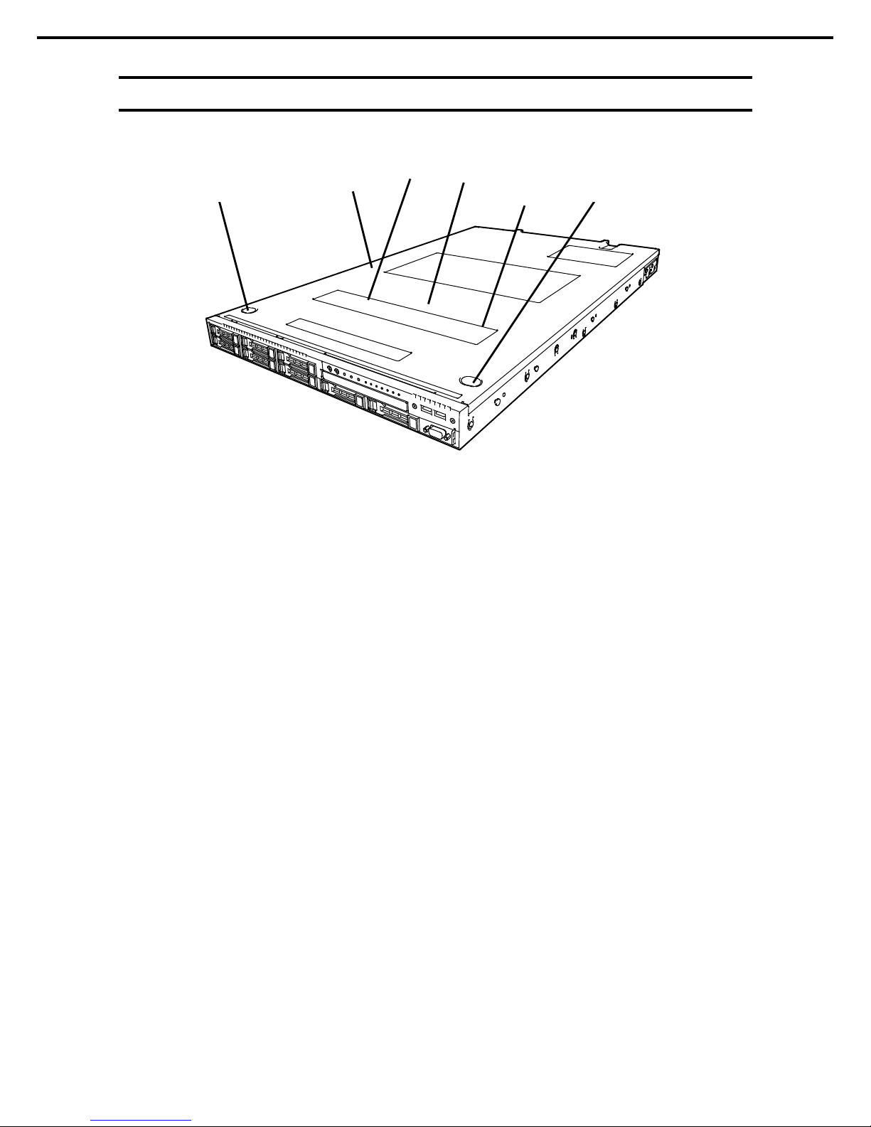
4.4
External View
(1) Top Cover
(2) Release Button.
(3) Fan Unit Top Cover
(4) Latch for fixing Fan Unit Top Cover
(2)
(1)
(3)
(2)
(4)
(4)
Page 30
4. Names and Functions of Parts
Express5800/R120f-1E User’s Guide
30
Chapter 1 General Description
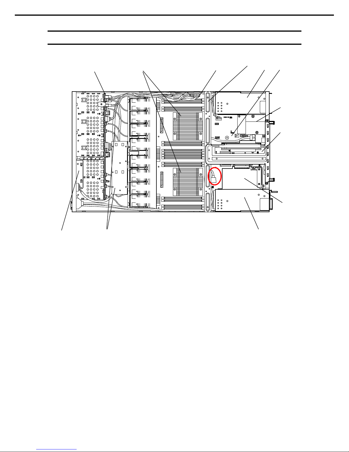
4.5
Internal View
(1) Front Panel Board
(2) Backplane
(3) Cooling Fan
-1 FAN1F/R
-2 FAN2F/R
-3 FAN3F/R
-4 FAN4F/R
-5 FAN5F/R
-6 F AN6F/R (optional)
-7 F AN7F/R (optional)
-8 F AN8F/R (optional)
FAN1 to FAN5 are factory installed. FAN6 t o FAN8 are
required in 2-CPU c onfiguration.
(4) Processor ( Optional)
(mounted below the heat sink)
(5) DIM M (optional)
(6) Support Bar
(7) M otherboard
(8) Slot for LOM Card
Assigned PCI sl ot number is "1B".
(9) PCI Riser Card
(10) Slot for RAID Controll er
Assigned PCI sl ot number is "1A".
(11) Power Supply Unit
(12) Battery Tray for RAID Controller
(2)
(1)
(5)
(11 )-1
(7)
(9)
(10)
(3)-1
(3)-2
(3)-3
(3)-4
(3)-5
(3)-6
(3)-7
(3)-8
(12)
(4)
(6)
(11 )-2
(8)
Page 31

4. Names and Functions of Parts
Express5800/R120f-1E User’s Guide
31
Chapter 1 General Description
4.6
Motherboard
(23)
(8)-1
(13)
(18)
(17) (16)
(15)
(12)
(10)
(9)
(26)
(8)-2
(7)
(6)
(5)
(4) (3)
(2)
(1)-1
(2)
(1)-2
(2)
(19)
(24)
(20)
(11)
(22)
(21)
(25)
(27)
Page 32

4. Names and Functions of Parts
Express5800/R120f-1E User’s Guide
32
Chapter 1 General Description
(1) Processor (CPU) Socket
-1: Processor #1 (CPU #1)
-2: Processor #2 (CPU #2)
(2) DIMM Socket
(3) Front Panel Connector
(4) Fan Connector
(5) Po wer Connector for Fan Unit
(6) Po wer Connector f or SAT A Optical Disk Drive
(7) Po wer Connector for HDD BP
(8) Po wer Connector
-1: Standard power unit (POW #1)
-2: Optional power unit (POW #2)
(9) LOM Card Connector
(10) Lithium Battery
(11) Unused Connector
(12) Clear Password Jumper Switch
(13) Clear CMOS Jumper Switch
(14) SW-RAI D Jumper Switch
(15) USB Memory Module Connector
(16) Front Video Connector
(17) Connector for Optional COM
Con nect an additional RS-232C connector kit N8117-01A
to use t his port as a ser ial p ort .
(18) SPI Mezzanine Connector
EXPRESSSCOPE Pr ofile Key (SPI memory) has been
installed, where BIOS and BMC configuration data is
stored. R elocat e it when replacing mother board to inherit
configuration data.
(19) Unused Connector
(20) TPM Kit Connector
(21) SAT A Connector (for opt ical disk drive)
(22) PCI Riser Card Connector (for low profile card)
For the support ed card specif icati ons, see Chapter 2 (1.12
PCI card).
(23) PCI Riser Card Connector (for full height card)
For the support ed card specif icati ons, see Chapter 2 (1.12
PCI card).
(24) SAT A HDD Connector
(25) Connectors for External Devices (See page 27)
(26) RAID Controller Connector
(27) USB Connector (front)
Page 33

4. Names and Functions of Parts
Express5800/R120f-1E User’s Guide
33
Chapter 1 General Description
4.7
Status Indicators
4.7.1
POWER LED ( )
POWER LED indi cates power ON/OFF status of the server.
POWER LED pattern
Description
On (green)
The server is normally power ed on.
Off The server is off-powered.
The server is in halt status.
4.7.2
STAT U S LED 1, 2 ( )
While hardware is operating normally, STATUS LED 1 lights green. STATUS LED 2 is off.
STATUS LED 1 is off or STATUS LED 2 lights/flashes amber if there is a hardware failure.
Tips
If NEC ESMPRO is installed, you can view error logs to check the causes of
fai lures .
LED pattern
Description Solution
STAT US LED 1
STATUS LED 2
On (green) Off The server is operating normally. −
On (green) On (amb er) Initialization of BMC is in pr ogress. Wait until initialization completes.
Flashing (green) Off Memory is in a d egraded state Identify the device in degr aded state by using
BIOS Setup Utility (SETUP), and replace it as
soon as possible.
A correctable memory error has often
occurred.
Operating while CPU error is det ected.
In redundant power configuration, power is
not supplied to either of power unit.
Off Off The power is off. Turn on the server.
POST is in progr ess. Wait for a while. STATUS LED will turn green
after POST completes.
W atc hd og timer expired. Turn the power off and then turn it on.
If POST screen displays any err or mess age,
take notes of the mess age, and contact your
sales representative.
Memory dump is being requested.
Not e: It remains green if the dump is c aused
by software.
Wait until the memory dump is completed.
Page 34

4. Names and Functions of Parts
Express5800/R120f-1E User’s Guide
34
Chapter 1 General Description
LED pattern
Description Solution
STAT US LED 1
STATUS LED 2
Off
On (amber) A temperature alarm was detected. Check the internal fan for dusts. Also check if
the fan unit is properly connected.
If the LED indication does not change, contact
your s al es repres entative.
A CPU error occurred. Turn the power off and then turn it on.
If POST displays any err or m ess ag e, take
notes of the message, and contact your s al es
representative.
Abnormal CPU temperature is detected.
A PCI system error occurred
A PCI parity error occurred
A PCI bus error occurred.
A voltage alarm was detected. Contact your sales representative.
Fan error was detected.
Sensor error was detected.
A CPU temper ature alarm was detected.
An error occurred on Intel Node Manager
(one of the features of E XPRESSSCOPE
Engine 3).
Off Flashing
(am ber)
Power supply unit is failing (in power
redundant configuration).
Contact your sales represent ative.
A fan alarm was detected.
Check if the internal fan cable is properly
connect ed.
If the LED indication does not change, contact
your s al es repres entative.
A temperature warning was detected. Check the internal f an for dusts. Also check if
the fan unit is properly connected.
If the LED indication does not change, contact
your sales repres entative.
A voltage warning was detected Contact your sales representative.
One or more hard disk drives ar e failing
(excluding RAID0 or non-RAID
configuration).
Page 35

4. Names and Functions of Parts
Express5800/R120f-1E User’s Guide
35
Chapter 1 General Description
4.7.3
LINK/ACT LED ( 1, 2, 3, 4)
LINK/ACT LED on front panel indicates the status of LAN port.
The number of LEDs depends on an optional LOM card installed.
LINK/ACT LED pattern
Description
On (green)
The server is c onnected with network normally.
Flashing (green)
The server is accessing network.
Off
The server is disconnected from network.
4.7.4
Optical Disk Drive Access LED
The LED for optical disk drive at the front of the server flashes when a CD or DVD is being accesse d.
4.7.5
UID LED (ID)
UID LED is provided one each at the front and rear of the server. If you press UID Switch provided at the
front or rear of the server, the light turns on. If you press it again, the light turns off. It flashes when
commands from software are received.
This LED is used to identify the target server among multiple servers installed in a rack. Especially when
performing maintenance from behind the server, lighting the LED will help you to identify which server to
work with.
UID LED pattern
Description
On (blue)
The UID s witch is press ed.
Off
The UID s witch is not pressed.
4.7.6
Power Capping LED
Power Capping LED indicates the status of Power Capping feature as shown below.
Power Capping LED pattern
Description
On (green)
Power Capping f eature is enabled.
Flashing (green)
Power Capping is enabled and power control (cappi ng) is working.
Off
Power Capping featur e is dis abled.
Note
The Power Capping LED seems to be lit or flashing amber when STATUS LED is lit or
flashing amber. The amber ST ATUS LED indicates a hardware failure. C ontact your s al es
representative.
Page 36

4. Names and Functions of Parts
Express5800/R120f-1E User’s Guide
36
Chapter 1 General Description
4.7.7
LED on a hard disk drive
Each HDD is equipped with DISK LED.
DISK LED 1, 2 pattern
Description Solution
DISK LED 1
DISK LED 2
Flashing (green)
Off
Hard disk drive is being access ed.
–
Off On (amb er)
(only when RAID
system is
configured)
Hard disk drive is f ailing. Contact your sales represent ative.
Flashing (green) Flashing (amber )
(only when RAID
system is
configured)
Rebuild is in progress.
When the failed hard disk drive is replaced,
rebuild process starts automatically (auto
rebuild f eatur e).
–
Off
Off
Hard disk drive is halt ed.
–
Important Observe the following precaution s whenever you use the auto r ebuild
feature.
• Do not turn off or reboot the server while a HDD is being rebuilt.
• Wait at least 90 seconds before installing a HDD after removing one.
• Do not replace a HDD while another HDD is being rebuilt.
DISK LED 1 (green)
DISK LED 2 (amber)
Page 37

4. Names and Functions of Parts
Express5800/R120f-1E User’s Guide
37
Chapter 1 General Description
4.7.8
LEDs for LAN connectors
The LAN connectors have LINK/ACT LED and SPEED LED.
Management LAN
connec t or
LAN connector
LINK/ACT
LED
LINK/ACT
LED
SPEED
LED
SPEED
LED
Equipped with N8100-156
Management LAN
connec t or
LAN connector
LINK/ACT
LED
LINK/ACT
LED
SPEED
LED
SPEED
LED
Equipped with N8100-155
Management LAN
connec t or
LAN connector
LINK/ACT
LED
LINK/ACT
LED
SPEED
LED
SPEED
LED
Equipped with N8100-154
Page 38

4. Names and Functions of Parts
Express5800/R120f-1E User’s Guide
38
Chapter 1 General Description
• LINK/ACT LED ( 1, 2, 3, 4, M)
This LED indicates the status of the LAN port.
LINK/ACT LED pattern
Description
On (green)
The server is c onnected with network normally.
Flashing (green)
The server is accessing network.
Off
The server is disconnected from network.
• SPEED LED ( 1, 2, 3, 4, M)
This LED indicates which network interface is used.
SPEED LED pattern
Description
On (amb er)
The port is operating with 1000BASE-T interf ac e.
On (green)
The port is operating with 100BASE-T X interf ac e.
Off
The port is operating with 10BASE-T int er f ace.
When N8100-154 1000BASE-T LOM card (4ch) is installed
SPEED LED pattern
Description
On (amb er)
The port is operating with 1000BASE-T interf ac e.
On (green)
The port is operating with 100BASE-T X interf ac e.
Off The port is operating with 10BASE -T interf ac e.
When N8104-155 10GBASE-T LOM card (2ch) is inst alled
SPEED LED pattern
Description
On (green)
The port is operating with 10GBASE-T int erface.
On (amb er)
The port is operating with 1000BASE-T interf ac e.
Off
The port is operating with 100BASE-T X interf ac e.
When N8104-156 10GBASE-SFP+ (2ch) + 1000BASE-T (2ch) LOM ca rd i s installed
– When operating with 10BASE-SFP+
SPEED LED pattern
Description
On (green)
The port is operating with 10GBASE-SFP+ interf ac e.
On (amb er)
The port is operating with 1000BASE-T int er f ace.
Off
The port is operating with 10BASE-T interface.
– When operating with 1000BASE-T
SPEED LED pattern
Description
On (amb er)
The port is operating with 1000BASE-T int erface.
On (green)
The port is operating with 100BASE-TX interf ac e.
Off
The port is operating with 10BASE-T interface.
Page 39

4. Names and Functions of Parts
Express5800/R120f-1E User’s Guide
39
Chapter 1 General Description
4.7.9
AC POWER LED on power unit
The power unit is equipped with AC POWER LED.
AC POWER LED pattern
Description
Solution
On (green)
The server is powered on.
–
Flashing (green) The power cabl e is connected and AC power is
supplied.
–
Cold Redundant feature is enabled.
(See page 95)
–
On (amb er) The power cabl e is not connected in redundant
power configur ation.
Connect th e power cable.
Power unit is f ailing.
Contact your sales represent ative.
Flashing (amber)
Power unit is f ailing.
Contact your sales represent ative.
Off The power is n ot supplied to t he server. Connect the power cable. If it is alread y
connect ed, cont act your s al es r epres entative.
AC POWER LED
Page 40

Express5800/R120f-1E User’s Guide
40
NEC Express5800 Series
Express5800/R120f-1E
Preparations
This chapter describes preparations for using this server.
1. Installing Internal Options
Describes how to install or remove optional devices.
You can skip this section if you do not add any optional devices.
2. Installation and Connection
Describes how to place the server and connect the cabl es.
2
2
Page 41

1. Installing Internal Options
Express5800/R120f-1E User’s Guide
41
Chapter 2 Preparations
1.
Installing Internal Options
This section describes the instructions for installing supported optional devices and precautions.
If you did not purchase any optional device, you can skip this section.
Important
Use only the devices and cables specified by NEC. You will be charged to
repair damages, malfunctions, and failures caused by t he use of any devices
or cables not sp ecified for u se with this server even within the warranty
period.
1.1
Safety Precautions
Be sure to observe the following precautions to install and remove optional devices properly and safely.
WARNING
Be sure to observe the following precautions to use the server safety. Failure
to observe the precautions may cause death or serious injury. For details, see
Safety Precautions and Regulatory Notices.
• Do not disassemble, repair, or modify the server.
• Do not remove the lithium battery, NiMH battery, or Li-ion battery.
• Disconnect the power plug when installing and removing devices.
CAUTION
Be sure to observe the f ollowing precautions to use the server safely. Failure to
observe the precaution s may cause burns, injury, and property damage. For
details, see Safety Precautions and Regulatory Notice s.
• Do not drop
• Do not leave the server being pulled out.
• M ake sure to complete installation.
• Do not install with the cover removed.
• Do not get your fingers caught.
• High t emperature
• Electrical shock
Page 42

1. Installing Internal Options
Express5800/R120f-1E User’s Guide
42
Chapter 2 Preparations
1.2
Anti-static Measures
The server contains static-sensitive components. Take the measures below to avoid failures caused by static
electricity when installing or removing any optional devices.
• Wearing Anti-static Wrist Strap or Anti-static Gloves
Wear a wrist strap on your wrist and connect the wire to the chassis. If there is no wrist strap, touch an
unpainted metal surface of the chassis connected to the ground to discharge static electricity from your
body before touching the component. Touch the metal part occasionally to discharge the static electricity
while working on the component.
• Checking the Workplace
− Work on an anti-static floor or concrete floor.
− If you work on a place where st atic electricity is likely to be generated (such as carpet), be sure to
provide anti-static protection.
• Using the Work Table
Place the server on a mat with Electrostatic Discharge (ESD) protection.
• Clothing
− Do not wear wool or synthetic clothes.
− Wear anti-static shoes.
− Remove a ring, bracelet, wrist watch, and any kind of metal accesso ries.
• Handling of Components
− Keep the component in an anti-static bag until yo u install it to the server.
− Hold the component by the edges to avoid touching any terminals or mounting parts.
− Place the component in an anti-static bag when storing or moving them.
• Handling of Cables
When connecti ng a ca ble (a long LAN cable), static electricity may also be charged due to friction against
the floor. Connecting the charged cable with a device will cause damage to the devices in the system. It is
recommended to use a product su ch as elect rostatic discharge ki t to eliminate the static charge before
connecting the cable.
• Installing and Uninstalling the Optional Device
− To avoid electric hazard and malfunction, be sure to turn off the power switch of the server and unplug
the power cord from the outlet before installing or uninstalling any optional device.
− If the device is a hot-plug devi ce, you do not need to turn off the power switch.
− The devi ce contains static-sensitive electronic components. When installing or uninstalling the
optional device, wear an anti-static wrist strap on your wrist to avoid a failure ca used by the static
electricity. To use the strap, connect the wire to the chassis.
Page 43

1. Installing Internal Options
Express5800/R120f-1E User’s Guide
43
Chapter 2 Preparations
1.3
Overview of Installation and Removal
Install/remove components by using the following procedure.
CAUTION
Be sure to observe the follo wing pr ecautions to use the server safely. Fail ure to
observe the precautions may cause burns, injury, and property damage. For
details, see Safety Precautions and Regulatory Notice s.
• Do not drop the server
• Do not leave the server pulled out of the rack
• Replace the cover after installing components
• Beware of high temperatures
• Do not get your fingers caught when installing components
1. If the server is mounted on a rack, use UID Switch to identify the target server.
See Chapter 2 (1.4 Identifying Server (UID Switch)).
2. Remove Front Bezel.
See Chapter 2 (1.5 Removing Front Bezel).
If you want to install hard disk drives only, go to step 10.
3. Turn off the server.
See Chapter 3 (6. Turning Off the Server).
4. Disconnect the power cord from the outlet and the server.
Important
• After disconnecting the power cord from th e server, wait for at least 30
seconds before continuing to work because cooling fan, hard disk drive,
and other components are operating for a few seconds .
• M ake sure AC POWER LED on power supply unit is unlit.
5. Pull out the server from rack and put it on a flat rigid desk . See Chapter 2 (2.1 Installation) for details.
Important
Do not leave the server being pulled out from the rack.
6. Remove Top Cover.
See Chapter 2 (1.6 Removing Top Cover).
7. Depending on the components to be installed or removed, follow the procedure in order.
See Chapter 2 (0 TPM Kit ) to (1.14 Use of Internal Hard Disk Drives in the RAID System).
8. Attach Top Cover.
See Chapter 2 (1.15 Installing Top Cover).
9. Mount the server onto the rack.
See Chapter 2 (2.1.2 (1) Installation).
10. Install hard disk drives
See Chapter 2 (1.16 Hard Disk Drive).
Page 44

1. Installing Internal Options
Express5800/R120f-1E User’s Guide
44
Chapter 2 Preparations
11. Install power supply units
See Chapter 2 (1.17 Power Supply Unit).
12. Attach Front Bezel.
See Chapter 2 (1.18 Installing Front Bezel).
This is the end of the installation or removal procedures for internal options.
Continue the setup with reference to Chapter 2 (2.2 Connection).
Page 45
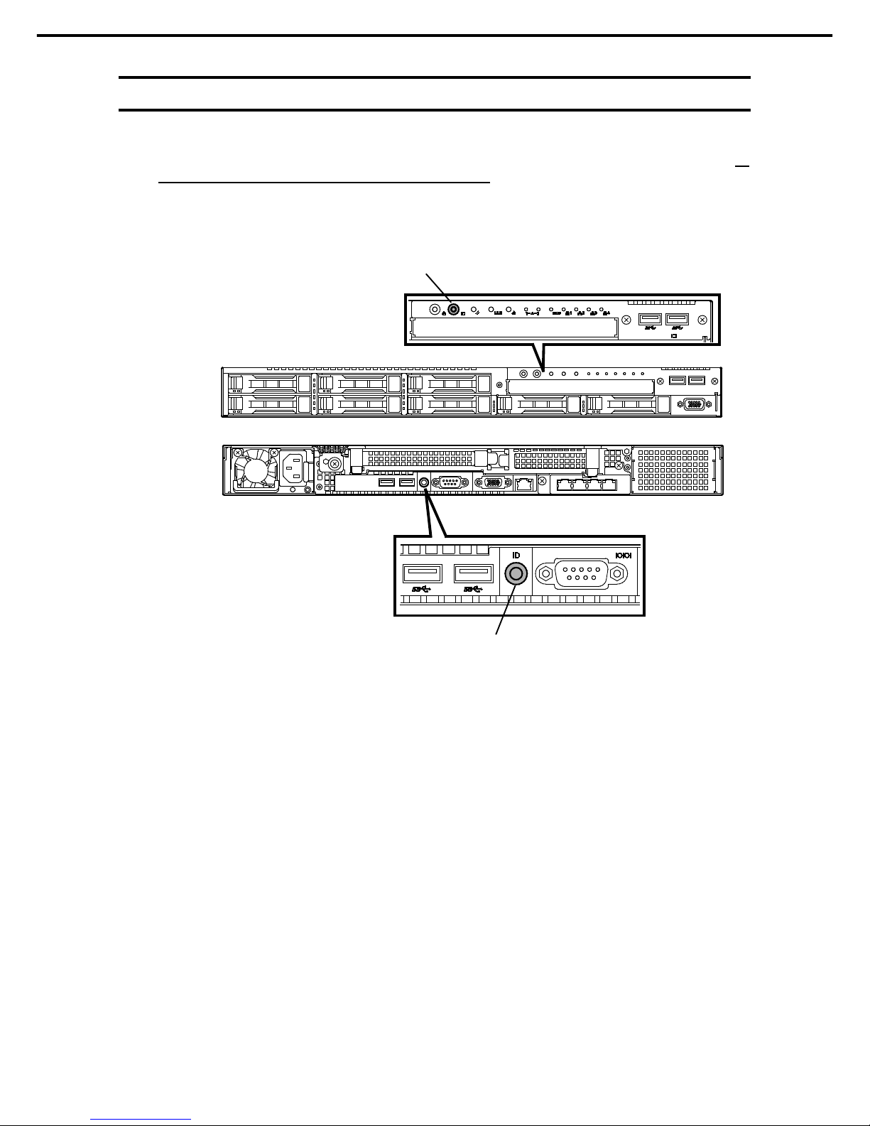
1. Installing Internal Options
Express5800/R120f-1E User’s Guide
45
Chapter 2 Preparations
1.4
Identifying Server (UID Switch)
Using Unit ID ( UID) Switch helps you to identify the target server from several servers in one rack.
When servers are running on a rack, before you turn the server off or disconnect a cabl e from the server, be
sure to identify the target server by using UID Switch first.
To turn UID LED on, press UID Switch. When it is pressed again, the LED will be off.
UID Switch / LED
UID Switch / LED
REAR
FRONT
Page 46
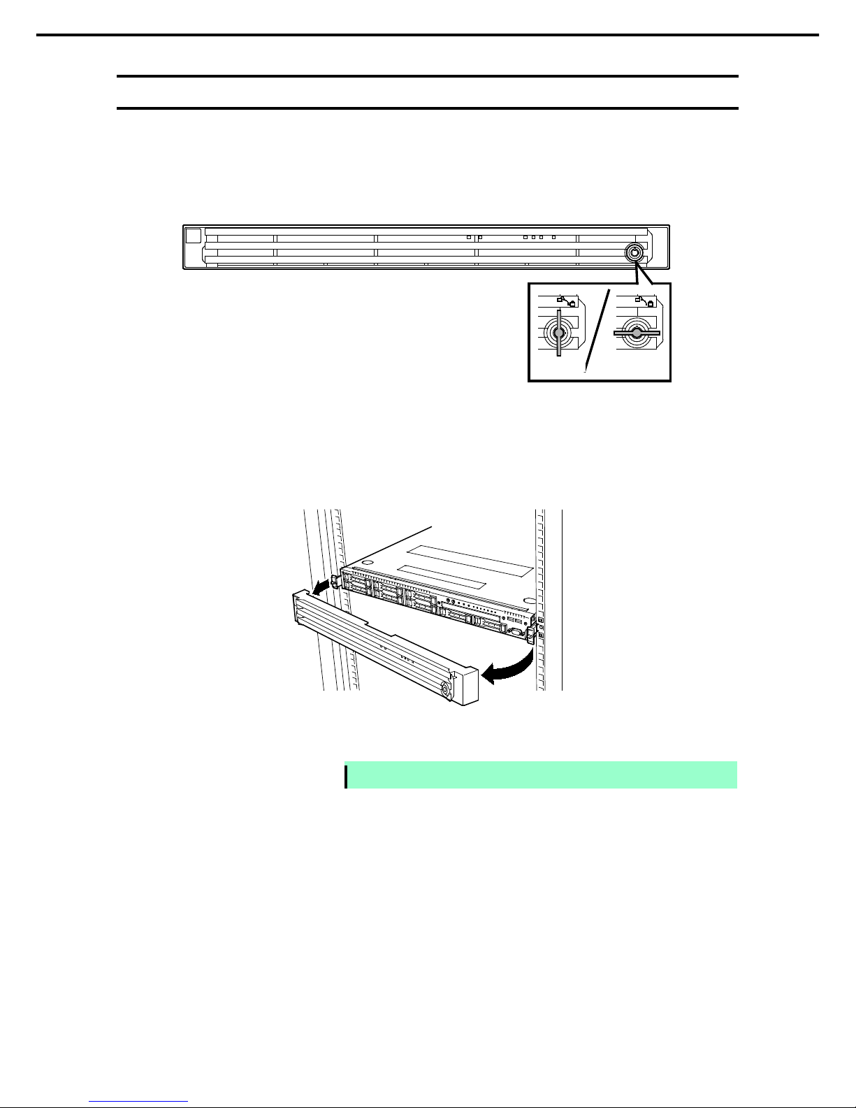
1. Installing Internal Options
Express5800/R120f-1E User’s Guide
46
Chapter 2 Preparations
1.5
Removing Front Bezel
Remove Front Bezel when pressi ng POWER Switch or removi ng Top Cover.
1. Insert the attached Bezel Lock Key into the key slot and turn the key to the Front Bezel si de while
pressi ng it lightly to release the lock.
2. Hold the right end of Front Bezel and pull it toward you, and remove the right end from the chassis.
3. Hold the left end of Front Bezel and pull it toward you, and remove the left end from the chassis.
Note
Be c areful not to pr ess POW ER Switch.
Unlocked
Locked
Page 47

1. Installing Internal Options
Express5800/R120f-1E User’s Guide
47
Chapter 2 Preparations
1.6
Removing Top Cover
Remove Top Cover when installing or removing the optional component or change internal cable connection.
1. See steps 1 to 5 in Chapter 2 (1.3 Overview of Installation
and Removal) for preparations.
2. Loosen Cap Screw located on rear panel.
3. Slide Top Cover toward the rear of the server while
pressi ng Release Button on the cover.
4. Lift the cover, and remove it from the server.
Page 48

1. Installing Internal Options
Express5800/R120f-1E User’s Guide
48
Chapter 2 Preparations
1.7
TPM Kit
This section describes the procedure for installing optional TPM Kit.
1.7.1
Installation
Install TPM Kit in the following procedure.
1. See steps 1 to 6 in Chapter 2 (1.3 Overview of Installation and Removal) for preparations.
2. Install TPM Kit and secure it by pushing the nylon rivet attached to TPM Kit.
Important
TPM Kit once installed cannot be removed.
Ask your sales representative if you want to remove the TPM Kit.
Connector for TPM Kit
Page 49

1. Installing Internal Options
Express5800/R120f-1E User’s Guide
49
Chapter 2 Preparations
1.8
Processor (CPU)
You can configure the multi-processor system by adding an optional processor (CPU).
Important
• Avoid static electricity to work with the procedure below. For details, see
Chapter 2 (1.2 Anti-static Measures).
• Installing a third-party CPU
may cause a failure. Repair of the server due
to failures or damage r esulted from installing such a CPU will be charged.
Tips
After adding the processor, W indows reco rds the event log to System categ ory of
Event Viewer, but it is no problem for operation.
1.8.1
Maximum number of processor cores supported by this server
The maximum number of processo r cores (logical processors) available on the server depends on the
architecture (x86 architecture) and OS specs.
Maximum number of processor cores
OS
The maximum number of
logical processors supported
by O S
The maximum number of
logical processors supported
by this s er ver
Microsoft Windows Server 2008 Standard
Microsoft Windows Server 2008 Ent erprise
32 *1 32
Microsoft Windows Server 2008 R2 Standard (x64)
Microsoft Windows Server 2008 R2 Enterprise (x64)
256 *1 48
Microsoft Windows Server 2012 Standard
Microsoft Windows Ser ver 2012 Dat acenter
Microsoft Windows Server 2012 R2 Standard
Microsoft Windows Server 2012 R2 Datacenter
640 *1 48
VMware ESXi 5.1
160
48
VMware ESXi 5.5 320 48
*1: W hen Hyper- V is used, th e m aximum numb er of logical pr oc essors is as sh own below:
Windows Server 2008: 24
Windows Server 2008 R 2: 64
Windows Server 2012, Windows Server 2012 R2: 320
Page 50

1. Installing Internal Options
Express5800/R120f-1E User’s Guide
50
Chapter 2 Preparations
1.8.2
Installation
Follow the steps below to inst all the CPU.
1. See steps 1 to 6 in Chapter 2 (1.3 Overview of Installation and Removal) for preparations.
2. Locate the CPU socket to which you are going to install a CPU.
3. Remove the protective cover from the CPU socke t.
Note
Keep the removed prot ective c over f or future use.
Page 51

1. Installing Internal Options
Express5800/R120f-1E User’s Guide
51
Chapter 2 Preparations
4. Push down the socket lever marked with " →" once to unlatch it from the hook, then slowly open
the lever until it stops.
5. Push down the socket lever marked with "
← " once to unlatch it from the hook, then slowly open
the lever until it stops.
6. Lift the plate.
Important
Do not to uch the sock et cont acts.
Page 52

1. Installing Internal Options
Express5800/R120f-1E User’s Guide
52
Chapter 2 Preparations
7. Put the additional CPU on the CPU socket slowly and gently.
For easy installation, hold edges of CPU with your thumb and index fingers so that the notch is aligned
with the key on the CPU socket.
Important
• Be sure to hold the CPU only at the edges.
• Pay attention not to touch the bottom of the CPU (pin section).
Note
• Ins ert the CPU while aligning the notch on the CPU
with the key on the CPU
soc ket.
• Bring down the CPU straight without tilting or sliding it in the socket.
8. Lightly push the CPU to the CPU socket, and close the plate.
9. Close the socke t lever marked with "
← " to fix it.
Page 53

1. Installing Internal Options
Express5800/R120f-1E User’s Guide
53
Chapter 2 Preparations
10. Close the socke t lever marked with " →" to fix it.
11. Put the heat sink on the CPU and fix the heat sink with four screws.
Temporarily tighten the four screws diagonall y, then tighten them securely.
Make su re that the scr ew aligns with the screw hole. If not, the scr ew may damage the motherboard.
12. Make sure that the heat sink is installed on a level with the motherboard.
Note
• If the heat sink is not level, r emove it, and then install it again.
The following pr obably causes the heat sink not to be level:
– The CPU is not positioned correctly.
– All screws are not completely tightened.
• D o not move the s ecured heat sink.
REAR
FRO NT
Page 54

1. Installing Internal Options
Express5800/R120f-1E User’s Guide
54
Chapter 2 Preparations
13. Install an additional fan unit provided with additional CPU board.
Remove fan cover from the slot where you are going to install an additional fan unit.
14. Remove the tray for RAID Controller.
15. Insert the additional fan unit straight into fan cage.
16. Connect cables for additional fan unit to the backplane.
17. Insert the tray for RAID Controller.
18. Continue to install or remove internal options, mount and connect the server, and turn it on.
Connectors for additional fan unit
Page 55

1. Installing Internal Options
Express5800/R120f-1E User’s Guide
55
Chapter 2 Preparations
19. Run BIOS Setup Utility (SETUP) to confirm the following settings. See Chapter 2 (1. System BIOS) in
"Maintenance Guide".
Advanced → Processor Configuration → Processor Information
[CPU ID]
[L2 Cache RAM]
[L3 Cache RAM]
1.8.3
Replacement / Removal
Important
• Do not remove any CPU unless it is failed.
• To remove the heat sink from the CPU, first turn the heat sink to the left
and right lightly to make sure that the heat sink can be apart from the CPU.
Removing the heat sink with it adhering to the CPU may cause the CPU
and/or CPU socket to be defected.
To remove CPU, reverse the installation procedure.
Perform the following steps if CPU is removed.
1. Mount the protective cover to CPU socket.
2. Remove the additional fan unit.
3. Mount the fan cover.
Page 56

1. Installing Internal Options
Express5800/R120f-1E User’s Guide
56
Chapter 2 Preparations
1.9
DIMM
Install a Dual Inline Memory Module (DIMM) to a DIMM socket on the motherboard in the server.
The motherboard provides 16 sockets to inst all DIMMs.
Important
• Avoid static electricity to work with the procedure below. For details, see
Chapter 2 (1.2 Anti-static Measures).
• Use only the specified DIMM s. Installing a DIMM from a third party may
damage not only the DIMM but the motherboard. Y ou will be charged to
repair failures or damages caused by the use of such products even within
the warranty period.
Tips
Up t o 512 GB (32 GB x 16) c an be installed in 2-CPU configuration. Up to 256 GB
(32 GB x 8) can be installed in 1-CPU configuration. No DIMMs ar e factory
installed in st andard configuration.
1.9.1
Maximum supported memory size
The maximum available memory size on the server depends on the architecture and OS specs.
Maximum memory sizes
OS
Maximum memory
size supported on
each OS
Maximum memory size supported
on the server
Microsoft Windows Server 2008 Standard *1 4GB
4 GB (using HW -DEP feature)
* Default factory settings
Approximately 2 GB (not using
HW-DEP feature)
Not e: If you are not using the
HW-DEP featur e, set Execute
Disable Bit (X D Bit) to
Disabled in the BIOS s ettings.
Microsoft Windows Server 2008 R2 Standard *1
32GB
32GB
Microsoft Windows Server 2008 Ent erprise *1
64GB
64GB
Microsoft Windows Server 2008 R2 Enterprise *1
2TB
512GB
Microsoft Windows Server 2012 Standard *1
Microsoft Windows Server 2012 Datacenter *1
Microsoft Windows Server 2012 R2 Standard *1
Microsoft Windows Server 2012 R2 Datacenter *1
4TB 512GB
VMware ESXi 5.1 *2
2TB
512GB
VMware ESXi 5.5 *2
4TB
512GB
*1: Shown below is the maximum memory size when Hyper-V is used:
- Windows Server 2008 Standard, Windows Server 2008 R2 Standard : 32GB
- Windows Server 2008 Enterprise, Windows Server 2008 R2 Enterprise : 1TB
- Windows Server 2012 ,Windows Server 2012 R2: 4TB
*2: Up to 1 TB on virtual machine.
Page 57

1. Installing Internal Options
Express5800/R120f-1E User’s Guide
57
Chapter 2 Preparations
1.9.2
Memory Clock
The server supports the memory clock speed of DDRL4-1600/1866/2133 MHz but the actual memory clock
speed depends on CPU and memory configuration. The all of DIMMs operate at the same clock speed.
Code Number
(CPU)
DIMM type Clock speed
N8101-768F
(E5-2603v3)
N8102-631F
4GB additional memory board (1x4GB/R)
N8102-632F
8GB additional memory board (1x8GB/R)
N8102-633F
16GB additional memory board (1x16GB/R)
N8102-634F
32GB additional memory board (1x32GB/LR)
N8102-637
16GB additional memory board (2x8GB/R)
N8102-638
32GB additional memory board (2x16GB/R)
N8102-642
32GB additional memory board (2x16GB/R)
1600 MHz
N8101-770F
(E5-2620v3)
N8101-734F
(E5-2630v3)
N8101-735F
(E5-2630Lv3)
N8101-773F
(E5-2640v3)
N8102-631F
4GB additional memory board (1x4GB/R)
N8102-632F
8GB additional memory board (1x8GB/R)
N8102-633F
16GB additional memory board (1x16GB/R)
N8102-634F
32GB additional memory board (1x32GB/LR)
N8102-637
16GB additional memory board (2x8GB/R)
N8102-638
32GB additional memory board (2x16GB/R)
N8102-642
32GB additional memory board (2x16GB/R)
1866 MHz
N8101-736F
(E5-2650v3)
N8101-775F
(E5-2650Lv3)
N8101-776F
(E5-2660v3)
N8102-631F
4GB additional memory board (1x4GB/R)
N8102-632F
8GB additional memory board (1x8GB/R)
N8102-633F
16GB additional memory board (1x16GB/R)
N8102-634F
32GB additional memory board (1x32GB/LR)
N8102-637
16GB additional memory board (2x8GB/R)
N8102-638
32GB additional memory board (2x16GB/R)
N8102-642
32GB additional memory board (2x16GB/R)
2133 MHz
Page 58

1. Installing Internal Options
Express5800/R120f-1E User’s Guide
58
Chapter 2 Preparations
1.9.3
Memory RAS Feature
The server supports the following RAS features. Some restrictions (such as DIMM installation location) are
imposed on using the Memory Mirroring or Memory LockStep feature. See Chapter 2 (1.9.7 Using Memory
RAS Feature) for conditions appropriate to your requirements.
• Standard memory feature (x4 SDDC ECC memory) *1
• Memory Mirroring feature (restrictions imposed on DIMM configuration)
• Memory LockStep feature (x8 SDDC ECC memory) (restricti ons imposed on DIMM configuration)
• Memory Sparing feature (restrictions imposed on DIMM configuration)
*1: x4 SDDC is not supported on N8102-631F
Supported RAS features depend on additional memory board.
See the table below for RAS features supported by additional memory board.
Features support ed by additional memory boar d
Code Number and
Product Name
Standard
Feature
(x4 SDDC)
Memory
Mirroring
Feature
Memory
LockStep
Feature
(x8 SDDC)
Memory
Sparing
Feature
N8102-631F
4GB additi onal memory board (1x4GB/R)
N/A N/A N/A N/A
N8102-632F
8GB additi onal memory board (1x8GB/R)
N/A N/A N/A
N8102-633F
16GB additional memory board (1x16GB/R)
N/A N/A N/A
N8102-634F
32GB additional memory board
(1x32GB/LR)
N/A N/A N/A
N8102-637
16GB additional memory board (2x8GB/R)
N/A N/A
N8102-638
32GB additional memory board (2x16GB/R)
N/A N/A
N8102-642
32GB additional memory board (2x16GB/R)
N/A N/A N/A
: Supported
Page 59

1. Installing Internal Options
Express5800/R120f-1E User’s Guide
59
Chapter 2 Preparations
1.9.4
DIMM installation order
Note
DIMM installation order in 1-CPU configur ation differs from that in 2-CPU
configuration.
In 1-CPU configuration, install two DIMMs starting from the smallest slot number. If CPU2 is not installed,
CPU2_DIMM1 to CPU2_DIMM12 are disabled.
In 2-CPU configuration, alternately inst all two DIMMs starting from the smallest slot number of each CPU.
See the table below to find allowable combination of DIMMs. Any other combination of DIMMs than described
in this table is not allowed.
Code Number
N8102-
631F 632F 633F 634F 637 638 642
N8102-631F N/A N/A N/A N/A
N8102-632F
N/A N/A N/A N/A
N8102-633F N/A N/A N/A N/A
N8102-634F N/A N/A N/A
N/A N/A N/A
N8102-637 N/A N/A N/A N/A N/A
N8102-638 N/A N/A N/A N/A N/A
N8102-642 N/A N/A N/A N/A N/A N/A
: Allowed to be installed together
3
7
4
8
6
2
5
1
5
13
7
15
11
3
9
1
6
14
8
16
12
4
10
2
CPU1_DIMM 3
CPU1_DIMM 7
CPU1_DIMM 4
CPU1_DIMM 8
CPU1_DIMM 6
CPU1_DIMM 2
CPU1_DIMM 5
CPU1_DIMM 1
CPU2_DIMM 3
CPU2_DIMM 7
CPU2_DIMM 4
CPU2_DIMM 8
CPU2_DIMM 6
CPU2_DIMM 2
CPU2_DIMM 5
CPU2_DIMM 1
1CPU
configurati on
2CPU
configurati on
Page 60

1. Installing Internal Options
Express5800/R120f-1E User’s Guide
60
Chapter 2 Preparations
1.9.5
Installation
Install a DIMM by using the following procedure.
1. See steps 1 to 6 in Chapter 2 (1.3 Overview of Installation and Removal) for preparations.
2. Open levers on left and right sides of
DIMM slot, and remove the dummy cover.
Note
Keep the removed dummy cover for future use.
3. Push the DIMM straight into the socket.
When a DIMM is inserted into the socke t,
the lever automatically cl oses.
Important
• M ake sure the orientation of the DIMM . The DIMM has a notch, preventing
being incorrectly inserted.
• Do not apply too much pressure when you push a DIMM into t he socket.
Doing so can damage the socket or terminal part.
4. Continue to install or remove internal options, mount and connect the server, and turn it on.
5. Confirm that no error messages are displayed in POST screen.
If any error messages are displayed, see Chapter 3 (1. POST Error Message) in "Maintenance Guide".
6. Run BIOS Setup Utility, and select Memory Configuration and then Memory Information from the
Advanced menu. Make sure the capacity of added DIMM is displayed properly.
See Chapter 2 (1. System BIOS) in "Maintenance Guide".
7. Select Memory Configuration from the Advanced menu, and then specify Yes for Memory Retest.
After that, sel ect Save Changes and Exit to reboot.
8. Set the size of Paging File to the recommended value (total memory size x 1.5) or more.
If using a Windows OS, see Chapter 1 (7.1 Specifying Memory Dump Settings (Debug Information)) in
"Installation Guide (Windows)".
For other OS, follow the manual of the OS.
Key
Ke y sl ot
Page 61

1. Installing Internal Options
Express5800/R120f-1E User’s Guide
61
Chapter 2 Preparations
1.9.6
Removal / Replacement
To remove DIMM, reverse the installation procedure.
Be sure to install dummy cover to the slots from where DIMMs are removed.
Important
Failing to inst all dummy cover to vacant slot may cause malfunction of the
server due to insufficient co oling effect.
Note
When removing a defective DIMM, check err or messages displayed at POST or
NEC ESMPRO and check the DIMM s ocket where the defective DIMM is installed.
Follow the steps below after replacing or removing DIMMs.
1. Confirm that no error messages are displayed on POST. If any error message is displayed, see Chapter
3 (1. Post Error Message) in "Maintenance Guide".
2. Run BIOS Setup Utility, select Memory Configuration from the Advanced menu, and then specify Yes
for Memory Retest. After that, select Save Changes and Exit to reboot.
3. Set the size of Paging File to the recommended value (total memory size x 1.5) or more.
If using a Windows OS, see Chapter 1 (7.1 Specifying Memory Dump Settings (Debug Information)) in
"Installation Guide (Windows)".
For other OS, follow the manual of the OS.
1.9.7
Using Memory RAS Feature
This server has RAS feature including Standard Mem ory feature (x4 SDDC ECC memory), Memory Mirroring
feature, Memory Sparing feature, and Memory Lock Step (x8 SDDC ECC memory) feature. Single Device
Correction (SDDC) allows automatic correction of memory error (multi-bit error).
Note
• S ee List of features sup ported by additional memory board in 1.9.3 Memory
RAS Feature befor e using memory RAS f eature.
• Only the features that additi onal memory boar d supports can be used.
The memory area on the motherboard of the server is divided into four memory channels.
Memory Mirroring, Memory Lock Step, and Memory Sparing features keep memory redundancy between
memory channels by monitoring or altering memory active/inactive status, respectively.
Memory controll er Memory controll er
Page 62

1. Installing Internal Options
Express5800/R120f-1E User’s Guide
62
Chapter 2 Preparations
(1)
Memory Mirroring Feature
Memory Mirroring feature writes the same data into two groups of DIMMs (mirror set) corresponding with each
other between memory channels (channels 0 and 1 or channel 2 and 3) to provide data redundancy.
Note
• Memory Mirroring feature uses channels 0 an d 1 or channels 2 and 3.
• To use Memory Mirroring featur e, install N8102-637/638 additional memory
board (two DIMMs of same model).
• DIMMs used in mirror s et must be of the same model number.
Example: 2-CPU configuration
Tips
The operating s ystem can use a half of the total physical memory capacit y.
Memory controller
Memory controller
Mirror set
#3
Mirror set
#1
Mirror set
#4
Mirror set
#2
Data 1
Data 2
Data 3
Data 4
Data 1
Data 2
Data 3
Data 4
Mirror set
#8
Mirror set
#7
Mirror set
#6
Mirror set
#5
Page 63

1. Installing Internal Options
Express5800/R120f-1E User’s Guide
63
Chapter 2 Preparations
Memory Mirroring feature can be used under the following conditions:
• Install DIMMs in DIMM sockets to configure a mirror set.
• All the installed DIMMs must be the sam e capacity.
• See Chapter 2 (1. System BIOS) in "Maintenance Guide", check if your server supports Memory Mirroring
feature.
Select Advanced → Memory Configuration → Memory Inform ation, and check if Supported is
displayed in Mirroring.
• See Chapter 2 (1. System BIOS) in "Maintenance Guide" to change parameters as shown below.
Advanced → Memory Configuration → Memory RAS Mode → Change to Mirroring.
• After restart, run SETUP again, and check if "Mirrored" is displayed for the following parameter.
Advanced → Memory Configuration → Memory Information → CPUx_DIMMx Status
• Installation order depends on CPU configuration. See the figure below.
Memory Mirroring cannot be configured in the following case:
• Memory Mirroring within a specific memory channel
Notes on Configuring Memory Mirroring
In Memory Mirroring configuration, Memory RAS Mode menu is changed from "Mirroring" to "Independent"
in the following cases:
• When you additionally install DIMMs that unable to configure Memory Mirroring
• When you remove DIMMs that takes down Mem or y Mirroring
2
4
2
4
3
1
3
1
3
7
3
7
5
1
5
1
4
8
4
8
6
2
6
2
CPU1_DIMM 3
CPU1_DIMM 7
CPU1_DIMM 4
CPU1_DIMM 8
CPU1_DIMM 6
CPU1_DIMM 2
CPU1_DIMM 5
CPU1_DIMM 1
CPU2_DIMM 3
CPU2_DIMM 7
CPU2_DIMM 4
CPU2_DIMM 8
CPU2_DIMM 6
CPU2_DIMM 2
CPU2_DIMM 5
CPU2_DIMM 1
1CPU
configurati on
2CPU
configurati on
Page 64

1. Installing Internal Options
Express5800/R120f-1E User’s Guide
64
Chapter 2 Preparations
(2)
Memory Lock Step Feature (x8 SDDC)
In Memory Lock Step feature, the DIMMs in two groups corresponding to two memory channels (channels 0
and 1, or channels 2 and 3) is multiplexed and operated in parallel to enable x8 SDDC. With this feature, a
single device can detect and correct one to eight-bit error.
Note
• Memory LockStep featur e uses c hannels 0 and 1 or channels 2 and 3.
• To use Memory LockStep feature, install N8102-637/638 additional memory
board (two DIMMs of same model).
• DIMMs used in LockStep set must be of the s ame mod el number.
Memory controller
Memory controller
LockSt ep set
#3
LockSt ep set
#1
LockSt ep set
#4
LockSt ep set
#2
LockStep set
#8
LockSt ep set
#7
LockSt ep set
#6
LockSt ep set
#5
Page 65

1. Installing Internal Options
Express5800/R120f-1E User’s Guide
65
Chapter 2 Preparations
Memory Lock Step feature can be used under the following conditions:
• Install DIMMs in DIMM socket to confi gure a Lock Step set.
• All the installed DIMMs should have the same capacity.
• See Chapter 2 (1. System BIOS) in "Maintenance Guide" to change parameters as shown below.
Advanced → Memory Configuration → Memory RAS Mode → Change to LockStep.
• After restart, run SETUP again, and check if "Lock Step" is displayed for the following parameter.
Advanced → Memory Configuration → Memory Information → CPUx_DIMMx Status
• Installation order depends on CPU configuration. See the figure below.
Memory Lock Step cannot be configured in the following cases:
• Memory Lock Step between memory channels of different memory controllers (CPU)
• Memory Lock Step within the same memory channel
Notes on Configuring Lock Step
In Mem ory Lock Step configuration, Memory RAS Mode menu is changed from "Lock Step" to "Independent"
in the following cases:
• When you additionally install DIMMs that unable to configure Memory Lock Step
• When you remove DIMMs that takes down Memory Lock Step
2
4
2
4
3
1
3
1
3
7
3
7
5
1
5
1
4
8
4
8
6
2
6
2
CPU1_DIMM 3
CPU1_DIMM 7
CPU1_DIMM 4
CPU1_DIMM 8
CPU1_DIMM 6
CPU1_DIMM 2
CPU1_DIMM 5
CPU1_DIMM 1
CPU2_DIMM 3
CPU2_DIMM 7
CPU2_DIMM 4
CPU2_DIMM 8
CPU2_DIMM 6
CPU2_DIMM 2
CPU2_DIMM 5
CPU2_DIMM 1
1CPU
configurati on
2CPU
configurati on
Page 66

1. Installing Internal Options
Express5800/R120f-1E User’s Guide
66
Chapter 2 Preparations
(3)
Memory Sparing Feature
Memory Sparing feature puts a memory channel 2 of a memory controller in each CPU into standby status as
spare devices. If a correct able error occurs in a DIMM in the running memory controller, the feature
automatically changes the running DI MM from the failed one to a DIMM in the standby state to co ntinue the
processing.
Note
To use Memor y Sparing featur e, install N8102-622/623 additional memor y boar d
(three DIMMs of same model).
DIMMs installed in the system must be of the same model number.
Tips
The operating s ystem can use the DIMMs as those with capac
ities less than the
actual physical capacities. The capacities vary depending on the number of
DIMMs and the physical capacity per DIMM.
The following table shows configuration allowable for memory sparing and system logical memory capacity.
Number of CPUs Nu mber of DIMMs
Capacity of DIMM installed
16GB
1 2 24GB
4 48GB
6 72GB
8 96GB
2 4 48GB
6 72GB
8 96GB
10 120GB
12 144GB
14 168GB
16 192GB
Page 67

1. Installing Internal Options
Express5800/R120f-1E User’s Guide
67
Chapter 2 Preparations
Memory Sparing feature can be used under the following conditions:
• Install DIMMs in DIMM socke t to configure a spare set.
• DIMMs to be installed must be the sam e capacity.
• See Chapter 2 (1. System BIOS) in "Maintenance Guide", check if your server supports Memory Sparing
feature.
Select Advanced → Memory Configuration → Memory Inform ation, and check if Supported is
displayed in Sparing.
• See Chapter 2 (1. System BIOS) in "Maintenance Guide" to change parameters as shown below.
Advanced → Memory Configuration → Memory RAS Mode → Change to Sparing.
• After restart, run SETUP again, and check if "Spared" is displayed for the following parameter.
Advanced → Memory Configuration → Memory Information → CPUx_DIMMx Status
Memory controller
Memory controller
Spare set
#1
Spare set
#3
Spare set
#5
Spare set
#2
Spare set
#4
Spare set
#6
Spare set
#8
Spare set
#7
Standby
Running
Running
Standby
Page 68

1. Installing Internal Options
Express5800/R120f-1E User’s Guide
68
Chapter 2 Preparations
• Installation order depends on CPU configuration. See the figure below.
The following Memory Sparing cannot be configured.
• A DIMM of different capacity is installed.
• Sparing with DIMMs in different memory channel
Notes on Configuring Memory Sparing
In Memory Sparing configuration, Memory RAS Mode menu is changed to "Independent" in the following
cases:
• When you additionally install DIMMs that unable to configure Memory Sparing
• When you remove DIMMs that takes down Memory Sparing
3
3
4
4
2
2
1
1
5
5
7
7
3
3
1
1
6
6
8
8
4
4
2
2
CPU1_DIMM 3
CPU1_DIMM 7
CPU1_DIMM 4
CPU1_DIMM 8
CPU1_DIMM 6
CPU1_DIMM 2
CPU1_DIMM 5
CPU1_DIMM 1
CPU2_DIMM 3
CPU2_DIMM 7
CPU2_DIMM 4
CPU2_DIMM 8
CPU2_DIMM 6
CPU2_DIMM 2
CPU2_DIMM 5
CPU2_DIMM 1
1CPU
configurati on
2CPU
configurati on
Page 69

1. Installing Internal Options
Express5800/R120f-1E User’s Guide
69
Chapter 2 Preparations
1.10
Flash Backup Unit for RAID Controller
If a RAID controller (N8103-176/177/178/179) is installed, use the flash backup unit (FBU) to avoid data loss
caused by accidents including temporary blackout during a Write Back operation. The model of the flash
backup unit to be used depends on RAID controll er.
• For N8103-176/177/178, use N8103-181 Flash Backup Unit
• For N8103-179, use FBU provided with N8103-179.
1.10.1
Handling precautions
Observe the following when using FBU. Ignoring these precautions may cause damage to your data or other
devices.
• Use the FBU appropriate to the RAID controller to be used.
• The FBU is an elect ronic device sensi tive to static electricity. Before i nstallation, t ouch the metal fram e
part of the server to disch arge the static el ectricity from your body.
• Do not drop or bump the FBU.
• For recycl i ng and disp osing of the FBU, refer to the User’s Guide that comes with the RAID controller or
Flash Backup Unit.
1.10.2
Installing N8103-181 Flash Backup Unit
This section describes the procedure of installing an FBU for RAID controller.
1. See steps 1 to 6 in Chapter 2 (1.3 Overview of Installation and Removal) for preparations.
2. Remove the two screws and remove
the PCI riser card.
3. Remove the battery tray for RAID
controller.
Page 70

1. Installing Internal Options
Express5800/R120f-1E User’s Guide
70
Chapter 2 Preparations
4. Turn the battery tray for RAID
controller the other way, and mount
the FBU.
5. Mount the battery tray for RAID
controller.
6. Connect the FBU control cable (650
mm) that com es with FBU.
7. Remove the two screws from RAID
controller, and remove PCI bracket.
8. Mount the adapter to RAID
controller.
9. Connect the control cable of FBU to
RAID controller.
Align the connector on FBU control
cable with the black marking on
RAID controller, then connect the
FBU co ntrol cable.
Page 71

1. Installing Internal Options
Express5800/R120f-1E User’s Guide
71
Chapter 2 Preparations
10. Rem ove the two screws from server
chassis, and remove the RAID
controller bracket.
11. Install the RAID controller bracket to
RAID controller using two screws
removed in step 5.
12. Install RAID controller to the RAID
controller connector on motherboard,
using two screws removed in step 8.
13. Connect Mini SAS HD cable to RAID
controller.
14. Disconnect USB ca ble (for front) from
motherboard.
Page 72

1. Installing Internal Options
Express5800/R120f-1E User’s Guide
72
Chapter 2 Preparations
15. Connect Mini SAS HD cable to RAID
controller.
16. Connect USB cable (for front) to
motherboard.
17. Install the PCI riser card removed in
step 2.
1.10.3
Removal
For removing the FBU for RAID controller, reverse the installation procedure.
Page 73

1. Installing Internal Options
Express5800/R120f-1E User’s Guide
73
Chapter 2 Preparations
1.10.4
Installing FBU for N8103-179
Follow the steps below to inst all FBU.
1. See steps 1 to 6 in Chapter 2 (1.3 Overview of Installation and Removal) for preparations.
2. Remove the two screws, t hen
remove the PCI riser card.
3. Remove the battery tray for RAID
controller.
4. Turn the battery tray for RAID
controller the other way, and mount
the FBU.
5. Mount the battery tray for RAID
controller.
6. Connect the FBU control cable (750
mm) that com es with RAID
controller, to the FBU.
7. Connect the FBU control cable (750
mm) and Mini SAS cable to RAID
controller. Align the black marking on
connector of FBU control cable with
that on connector of RAID controller.
Page 74

1. Installing Internal Options
Express5800/R120f-1E User’s Guide
74
Chapter 2 Preparations
8. Remove one screw from the blank
cover on the PCI riser card (removed
in step 2) on which you are going to
mount the RAID controller, then
remove the blank cover.
9. Mount the RAID controller to the PCI
riser card, and secu re it with one
screw removed in step 6.
10. Mount the PCI riser card removed in
step 2.
Note
Keep the removed blank cover for fut ure us e.
1.10.5
Removing FBU
Remove the FBU in reverse order of installation procedure.
Page 75

1. Installing Internal Options
Express5800/R120f-1E User’s Guide
75
Chapter 2 Preparations
1.11
LOM Card
The server supports the LOM card which is the replaceable onboard network adapter.
Install the LOM card to the LOM card slot on motherboard. The motherboard has one slot to inst all the LOM
card.
Important
Avoid static electricity to work with the procedure below. For details, see
Chapter 2 (1.2 Anti-static Measures).
1.11.1
Installation
Follow the steps below to inst all the LOM card.
1. See steps 1 to 6 in Chapter 2 (1.3 Overview of Installation and Removal) for preparations.
2. Remove the screw that secures the PCI riser card, and remove the PCI riser card.
3. Remove the screws from the bracket.
4. Remove the bracke t.
Page 76

1. Installing Internal Options
Express5800/R120f-1E User’s Guide
76
Chapter 2 Preparations
5. Remove two screws from the motherboard.
6. Ali gn the pi n terminals of LOM card with the LOM card slot, i nsert the ca rd firmly, and secu re the card
with three screws.
7. Mount the LOM card bracket to motherboard and secure it with two screws removed in step 5.
8. Use the two screws removed in step 3 to mount the port cover that comes with LOM card.
9. Mount the PCI riser card removed in step 2.
Screws
Page 77

1. Installing Internal Options
Express5800/R120f-1E User’s Guide
77
Chapter 2 Preparations
1.11.2
Removal
Remove the LOM card in reverse order of installation steps.
Page 78

1. Installing Internal Options
Express5800/R120f-1E User’s Guide
78
Chapter 2 Preparations
1.12
PCI Card
This server provides PCI slots for riser card (one full-height PCI card and one low-profile PCI card), a slot for
LOM card, and a slot for RAID controller (total four PCI cards can be mounted).
Important
Avoid static electricity to work with the procedure below. For details, see
Chapter 2 (1.2 Anti-static Measures).
1.12.1
Notes
Read the following notes when installing or removing a PCI card.
• Do not touch the terminals of the riser cards and the leads of electronic components with your bare
hand. Fingerprints and dust left on them cause the server to malfunction due to a connection failure or
damage to the leads.
• Available type of PCI card depends on riser card. Make sure the card type before connecting it to riser
card.
• The server provides no connector to connect an LED connector which is supplied in RAID controller
used to indicate disk access.
• PCI slot number "1A" is assigned to the RAID controller slot, "1B" is assigned to LOM card sl ot, "1C" is
assi gned to the riser card for full-height PCI card, and "1D" is assi gned to the riser card for low-profile
PCI card.
• The search order for PCI bus slot on boot is as follows.
Slot 1A (for RAID controller) → Slot 1B (for LOM card) → Slot 1C (for full-height card) → Slot 1D (for
low-profile card)
• The PCI devices of the same type (incl uding onboard PCI device) may be recognized in different order
from those described above, depending on OS or RAID Configuration Utili ty. Check the slot location of
PCI device by PCI bus number, device number and function number shown in the table below.
PCI device
Bus number
Device number
Function number
LOM card LAN1 (when N8104-154F/155F/156F is
installed)
05h 0 0
LOM card LAN2 (when N8104-154F/155F/156F is
installed)
05h 0 1
LOM card LAN3 (when N81 04-154F/156F is installed)
05h 0 2
LOM card LAN4 (when N81 04-154F/156F is installed)
05h 0 3
Slot 1A dedic ated for RAID Controller
01h 0 0
PCIe slot 1C ( Full height)
0Ch 0 X
PCIe slot 1D ( Low pr ofile)
40h 0 X
PCIe x16 slot 1C (Full height)
81h 0 X
PCIe x16 slot 1D (Low profile) C0h 0 X
• If an additional LAN card is inst alled, it is hard to push the catch of the connector with your finger that is
connected to the LAN card. Disconnect the connector pushing the catch with a standard screwdriver. At
this time, be very careful for the screwdriver not to damage the LAN ca rd.
Page 79

1. Installing Internal Options
Express5800/R120f-1E User’s Guide
79
Chapter 2 Preparations
• If a bootable device such as a PCI card or USB device is added, the boot order may change.
In BIOS Setup Utility, select HDD Priorities from Boot menu and confirm the boot order.
Boot → HDD Priorities → Check the display
If the boot device is an HDD and located under an optional RAID control ler, the display is (Bus xx Dev
00) PCI RAID Adapter. Note that the value for xx changes depending on the PCI slot where a RAID
Controller is installed.
• For a RAID controller, LAN card (network boot), or Fibre Channel controller, if a hard disk drive on
which an OS is installed is connected, set the option ROM for that slot to Enabled. See Chapter 2 (1.
System BIOS) in "Maintenance Guide" for how to specify it.
1.12.2
Supported PCI cards and available slots
The following tables list supported cards and slots available for them. For details of the features of each
card, see the manual supplied with the card.
Tips
If the operation performance of PCI card differs from that of PCI Slot, th e PCI card
operates at low er frequency.
(1)
Standard riser card
Standard riser card
Remarks
Model
Product
name
Slot number #1A #1B #1D
PCI standar d PCIe 3.0
PCI slot performance
*1
x8 lane
PCI card type *2 x8 so cket
Transfer bandwidth
(per lane) *1
8Gb/s
Slot size
For RAID
controller
For LOM
card
Low profile
Available card size
220 mm
max.
N8103-176 RAID Control ler
(1GB, RAID 0/1)
[PCI Express 3.0(x8)]
– – Ded ic ated t o connect with internal hard
disk drive.
Choos e on e card (N8103- 176,
N8103-177, or N8103-178).
Flash Backup Unit [N8103-181] can be
mounted.
N8103-177 RA ID Controller
(1GB, RAID 0/1/5/6)
[PCI Express 3.0(x8)]
– –
N8103-178 RAID Control ler
(2GB, RAID 0/1/5/6)
[PCI Express 3.0(x8)]
– –
N8103-179 RAID Control ler
(2GB, RAID 0/1/5/6)
[PCI EXPRESS 3.0(x8)]
– –
Ded ic at ed to connect with external
devic es.
Flash Backup Unit is f actory installed
N8103-142 SAS Controller
[PCI Express 2.0(x8)]
– –
Ded ic at ed to connect with external
devic es.
N8103-184 SAS Controller
[PCI Express 3.0(x8)]
– –
N8 11 8-01 PCI SSD Adapter
[PCI Express 2.0(x4)]
– –
SSD to be mounted in PCI slot
N8190-159 Fibre Channel Contr oll er
(8Gbps/Optical)
[PCI Express 2.0(x8)]
– –
For connecting with external Fibre
Channel device
N8190-160 Fibre Channel Controller (2ch)
(8Gbps/Optical)
[PCI Express 2.0(x8)]
– –
N8190-157A Fibre Channel Contr oll er
(16Gbps/Optical)
[PCI Express 3.0(x8)]
– –
For connecting with external Fibre
Channel device
Page 80

1. Installing Internal Options
Express5800/R120f-1E User’s Guide
80
Chapter 2 Preparations
Standard riser card
Remarks
Model
Product
name
Slot number #1A #1B #1D
PCI standar d PCIe 3.0
PCI slot performance
*1
x8 lane
PCI card type *2 x8 so cket
Transfer bandwidth
(per lane) *1
8Gb/s
Slot size
For RAID
controller
For LOM
card
Low profile
Available card size
220 mm
max.
N8190-158A Fibre Channel Controller (2ch)
(16Gbps/Optical)
[PCI Express 3.0(x8)]
– –
N8104-150 1000BASE-T Adapter (1ch)
[PCI Express 2.0(x1)]
– –
For additional LAN port.
Card type: PCI Express 2.0 (x8)
N8104-151 1000BASE-T Adapter (2ch)
[PCI Express 2.0(x1)]
– –
For additional LAN port.
Card type: PCI Express 2.0 (x4)
N8104-152 1000BASE-T Adapter (4ch)
[PCI Express 2.0(x4)]
– –
For additional LAN port.
A LAN cable with modular cover
cannot be used.
N8104-145 1000BASE-T Adapter (2ch)
[PCI Express 2.0(x4)]
– –
For additional LAN port (Intel NIC).
N8104-149 10GBASE Adapter
(SFP+/2ch) [PCI Express 2.0(x8)]
– –
For additional LAN port.
Prepare SFP+ module N8104-129 if
needed.
N8104-148 10GBASE Adapter
(SFP+/2ch) [PCI Express 2.0(x8)]
– –
For additional LAN port (Intel NIC).
Prepare SFP+ module N8104-129 if
needed.
N8104-153 10GBASE-T Adapter (2ch)
[PCI Express 2.0(x8)]
– –
For additional LAN port
N8104-154 1000BASE-T LOM Card
(4ch) [PCI Express 2.0(x4)]
–
– For additional LAN port
Card type: PCI Express 2.0 (x8)
N8104-155 10GBASE-T LOM Card
(2ch) [PCI Express 3.0(x8)]
–
– For additional LAN port
N8104-156 10GBASE-SFP+(2ch)+
1000BASE-T(2ch) LOM Card
[PCI Express 3.0(x8)]
–
– For additional LAN port.
Prepare SFP+ module N8104-129 if
needed.
N8104-146 InfiniBand Adapter (1ch)
(FDR/Optical)
[PCI Express 3.0(x8)]
– –
For Infiniband c onnection.
Cannot be used together with each other.
N8104-147 InfiniBand Adapter (2ch)
(FDR/Optical)
[PCI Express 3.0(x8)]
– –
N8 11 7-01A Additional RS-232C connector *3 – –
For additional serial port B (RS-232C)
: Can be mounted, –: C annot be mounted
*1 Data transfer rate of PCI slot = Transfer bandwidth × Number of lanes
<Example> x8 lane = 64 Gbps (one-w ay)
*2 Connector size. Cards exceeding the number of sockets cannot be connected.
<Example> x4 socket can connect with x1 and x4 cards, but not x8 card.
*3 Use RS-232C cable (B).
Page 81

1. Installing Internal Options
Express5800/R120f-1E User’s Guide
81
Chapter 2 Preparations
(2)
N8116-39 riser card (PCIex8) (option)
Riser card (PCIex8)
Remarks
Model
Product
name
Slot number #1A #1B #1C #1D
PCI standar d PCIe 3.0
PCI slot performance
*1
x8 lane
PCI card type *2 x8 socket
Transfer bandwidth
(per lane) *1
8Gb/s
Slot size
For RAID
controller
For LOM
card
Full height Low profile
Available card size 22 0 mm max.
N8103-176 R AID Controller
(1GB, RAID 0/1)
[PCI Express 3.0(x8)]
– – – Dedicated to connect
with internal hard disk
drive.
Choos e on e card
(N8103-176, N8103-
177,
or N8103- 178).
Flash Backup Unit
[N8103-181] can be
mounted.
N8103-177 R AID Controller
(1GB, RAID 0/1/5/6)
[PCI Express 3.0(x8)]
– – –
N8103-178 R AID Controller
(2GB, RAID 0/1/5/6)
[PCI Express 3.0(x8)]
– – –
N8103-179 RAID Controller
(2GB, RAID 0/1/5/6)
[PCI EXPRESS 3.0(x8)]
– –
Ded ic at ed to connect
with external devices.
Flash Backup Unit is
factory installed
N8103-142 SAS Controll er
[PCI Express 2.0(x8)]
– –
Ded ic at ed to connect
with external devices.
N8103-184 SAS Controll er
[PCI Express 3.0(x8)]
– –
N8 11 8-01 PCI SSD Adapter
[PCI Express 2.0(x4)]
– –
SSD to be mounted in
PCI slot
N8190-159 Fibr e Ch ann el Controller
(8Gbps/Optical)
[PCI Express 2.0(x8)]
– –
For connecting with
external Fibre C hannel
device
N8190-160 Fibr e Ch ann el Controller (2ch)
(8Gbps/Optical)
[PCI Express 2.0(x8)]
– –
N8190-157A Fibr e Ch ann el Controll er
(16Gbps/Optical)
[PCI Express 3.0(x8)]
– –
For connecting with
external Fibre Channel
device
N8190-158A Fibre Ch ann el Controll er (2ch)
(16Gbps/Optical)
[PCI Express 3.0(x8)]
– –
N8104-150 1000BASE-T Adapter (1ch)
[PCI Express 2.0(x1)]
– –
For additional LAN port.
Card type: PCI Express
2.0 (x8)
N8104-151 1000BASE-T Adapter (2ch)
[PCI Express 2.0(x1)]
– –
For additional LAN port.
Card type: PCI Express
2.0 (x4)
N8104-152 1000BASE-T Adapter (4ch)
[PCI Express 2.0(x4)]
– –
For additional LAN port.
A LAN cable with
modular cover cannot be
used.
N8104-145 1000BASE-T Adapter (2ch)
[PCI Express 2.0(x4)]
– –
For additional LAN port
N8104-149 10GBASE Adapter
(SFP+/2ch) [PCI Express 2.0(x8)]
– –
For additional LAN port.
Prepare S FP + m odul e
N8104-129 if needed.
Page 82

1. Installing Internal Options
Express5800/R120f-1E User’s Guide
82
Chapter 2 Preparations
Riser card (PCIex8)
Remarks
Model
Product
name
Slot number #1A #1B #1C #1D
PCI standar d PCIe 3.0
PCI slot performance
*1
x8 lane
PCI card type *2 x8 socket
Transfer bandwidth
(per lane) *1
8Gb/s
Slot size
For RAID
controller
For LOM
card
Full height Low profile
Available card size 22 0 mm max.
N8104-148 10GBASE Adapter
(SFP+/2ch) [PCI Express 2.0(x8)]
– –
For additi onal LAN port
Prepare S FP + m odul e
N8104-129 if needed.
N8104-153 10GBASE-T Adapter (2ch)
[PCI Express 2.0(x8)]
– –
For additional LAN port
N8104-154 1000BASE-T LO M Card
(4ch) [PCI Express 2.0(x4)]
–
– – For additional LAN port
Card type: PCI Expr ess
2.0 (x8)
N8104-155 10GBASE-T LOM Card
(2ch) [PCI Express 3.0(x8)]
–
– – For additional LAN port
N8104-156 10GBASE-SFP+(2ch)+
1000BASE-T(2ch) LOM Card
[PCI Express 3.0(x8)]
–
– – For additional LAN port.
Prepare S FP + m odul e
N8104-129 if needed.
N8104-146 InfiniBand Adapter (1ch)
(FDR/Optical)
[PCI Express 3.0(x8)]
– –
For Infiniband
connecti on.
Cannot be us ed t ogether
with eac h other.
N8104-147 InfiniBand Adapter (2ch)
(FDR/Optical)
[PCI Express 3.0(x8)]
– –
N8 11 7-01A Additional RS-232C connector *3 – – –
For additional serial port B
(RS-232C)
: Can be mounted, –: C annot be mounted
*1 Data transfer rate of PCI slot = Transfer bandwidth × Number of lanes
<Example> x8 lane = 64 Gbps (one-w ay)
*2 Connector size. Cards exceeding the number of sockets cannot be connected.
<Example> x4 socket can connect with x1 and x4 cards, but not x8 card.
*3 Use RS-232C cable (B).
Page 83

1. Installing Internal Options
Express5800/R120f-1E User’s Guide
83
Chapter 2 Preparations
(3)
N8116-33 riser card (PCIex16) (option)
Riser card (PCIex16)
Remarks
Model
Produc
t name
Slot number #1A #1B
#1C
(2 CPUs
required)
#1D
(2 CPUs
required)
PCI standard PCIe 3.0
PCI slot performance
*1
x8 lane X16 lane
PCI card type *2 x8 socket X16 socket
Transfer bandwidth
(per lane) *1
8Gb/s
Slot size
For RAID
controller
For LOM
card
Full height Low profile
Available card size 220 mm max.
N8103-176 RAID Controller
(1GB, RAID 0/1)
[PCI Express 3.0(x8)]
– – – Dedicated to connect with
internal hard disk drive.
Choose one card
(N8103-176, N8103-177,
or N8103-178).
Flash Backup Unit
[N8103-181] can be
mounted.
N8103-177 RAID Controller
(1GB, RAID 0/1/5/6)
[PCI Express 3.0(x8)]
– – –
N8103-178 RAID Controller
(2GB, RAID 0/1/5/6)
[PCI Express 3.0(x8)]
– – –
N8103-179 RAID Controller
(2GB, RAID 0/1/5/6)
[PCI EXPRESS 3.0(x8)]
– –
Dedicated to connect with
external devices.
Flash Backup Unit is
factory installed
N8103-142 SAS Controller
[PCI Express 2.0(x8)]
– –
Dedicated to connect with
external devices.
N8103-184 SAS Controller
[PCI Express 3.0(x8)]
– –
N8118-01 PCI SSD Adapter
[PCI Express 2.0(x4)]
– –
SSD to be mounted in PCI
slot
N8190-159 Fibre Channel Controller
(8Gbps/Optical)
[PCI Express 2.0(x8)]
– –
For connecting with
external Fibre Channel
device
N8190-160 Fibre Channel Controller (2ch)
(8Gbps/Optical)
[PCI Express 2.0(x8)]
– –
N8190-157A Fibre Channel Controller
(16Gbps/Optical)
[PCI Express 3.0(x8)]
– –
For connecting with
external Fibre Channel
device
N8190-158A Fibre Channel Controller (2ch)
(16Gbps/Optical)
[PCI Express 3.0(x8)]
– –
N8104-150 1000BASE-T Adapter (1ch)
[PCI Express 2.0(x1)]
– –
For additional LAN port.
Card type: PCI Express 2.0
(x8)
N8104-151 1000BASE-T Adapter (2ch)
[PCI Express 2.0(x1)]
– –
For additional LAN port.
Card type: PCI Express 2.0
(x4)
N8104-152 1000BASE-T Adapter (4ch)
[PCI Express 2.0(x4)]
– –
For additional LAN port.
A LAN cable with modular
cover cannot be used.
N8104-145 1000BASE-T Adapter (2ch)
[PCI Express 2.0(x4)]
– –
For additional LAN port
N8104-149 10GBASE Adapter
(SFP+/2ch) [PCI Express 2.0(x8)]
– –
For additional LAN port.
Prepare SFP+ module
N8104-129 if needed.
Page 84

1. Installing Internal Options
Express5800/R120f-1E User’s Guide
84
Chapter 2 Preparations
Riser card (PCIex16)
Remarks
Model
Produc
t name
Slot number #1A #1B
#1C
(2 CPUs
required)
#1D
(2 CPUs
required)
PCI standard PCIe 3.0
PCI slot performance
*1
x8 lane X16 lane
PCI card type *2 x8 socket X16 socket
Transfer bandwidth
(per lane) *1
8Gb/s
Slot size
For RAID
controller
For LOM
card
Full height Low profile
Available card size 220 mm max.
N8104-148 10GBASE Adapter
(SFP+/2ch) [PCI Express 2.0(x8)]
– –
For additional LAN port
Prepare SFP+ module
N8104-129 if needed.
N8104-153 10GBASE-T Adapter (2ch)
[PCI Express 2.0(x8)]
– –
For additional LAN port
N8104-154 1000BASE-T LOM Card
(4ch) [PCI Express 2.0(x4)]
–
– – For additional LAN port
Card type: PCI Express 2.0
(x8)
N8104-155 10GBASE-T LOM Card
(2ch) [PCI Express 3.0(x8)]
–
– – For additional LAN port
N8104-156 10GBASE-SFP+(2ch)+
1000BASE-T(2ch) LOM Card
[PCI Express 3.0(x8)]
–
– – For additional LAN port.
Prepare SFP+ module
N8104-129 if needed.
N8104-146 InfiniBand Adapter (1ch)
(FDR/Optical)
[PCI Express 3.0(x8)]
– –
For Infiniband connection
Up to two cards can be
mounted.
Cannot be used together
with each other.
N8104-147 InfiniBand Adapter (2ch)
(FDR/Optical)
[PCI Express 3.0(x8)]
– –
N8117-01A Additional RS-232C connector *3 – –
– For additional serial port B
(RS-232C)
: Can be mounted, –: Cannot be mounted
*1 Data transfer rate of PCI slot = Transfer bandwidth × Number of lanes
<Example> x8 lane = 64 Gbps (one-way)
*2 Connector size. Cards exceeding the number of sockets cannot be connected.
<Example> x4 socket can connect with x1 and x4 cards, but not x8 card.
*3 Use RS-232C cable (B).
Page 85

1. Installing Internal Options
Express5800/R120f-1E User’s Guide
85
Chapter 2 Preparations
1.12.3
Installation
Install a PCI ca rd to the riser card in the following procedure.
Important
When installing a PCI card, make sure the connector of t he card fits the
connector of the riser card.
Note
• Check the card type (low-profile or full-height) wh ic h r es pect ive r is er car d
supports and the type of PCI card to be installed.
• T o install an FBU, s ee Chapter 2 (1.11 Flash Backup U nit for RAID Controller).
1. See steps 1 to 6 in Chapter 2 (1.3 Overview of I nstallation and Removal) for preparations.
2. Remove the two screws securing the PCI
riser card. Hold the both ends of the PCI
riser card and lift it off.
3. Confirm the installation slot with the reference to the table on 1.12.2 Supported PCI cards and available
slot s.
4. Remove one screw from the PCI riser card
and remove the blank cover.
Note
Keep the removed blank cover for fut ure us e.
5. Install a PCI ca rd to the PCI riser card.
Position the terminal part of the PCI card to
the PCI riser card slot and insert it.
Important
Do not touch the terminal part of riser card or PCI car d and the signal pins
of electric parts installed on the board. Installing boards with dirt or oil can
cause malfunction.
Note
• Make sure that the edge of a PCI card bracket is seated into the fixed sl ot.
• D epending on type of PC I car ds, the terminal part of the PCI card may be too
large to fit in the connector.
• If you have trouble installing the car d, r emove the card once and try again. If you
apply excessive pressure on the card, a PCI card or ris er card might break.
PCIe #1C
Full Height side
PCIe #1D
Low profile side
Page 86

1. Installing Internal Options
Express5800/R120f-1E User’s Guide
86
Chapter 2 Preparations
6. Secure the PCI card with the scr ew removed in step 4.
Tips
To connect a PCI c ard to the connector on motherboar d with c able, connect a
cable to PCI card before installing PCI riser card.
7. Connect the PCI riser card to the slot on
motherboard and secure the card with two
screws removed in step 2.
Position the terminal part of the PCI ri ser
card to the slot on the motherboard and
insert it.
8. Continue to install or remove internal options, mount and connect the server, and turn it on.
9. Make sure that no error messa ges are displayed on POST screen.
For details on POST error messages, see Chapter 3 (1. POST Error Message) in "Maintenance Guide".
10. Run the configuration utility of the card to set up the board as needed.
For details, see the manual that comes with the card. If a PCI card including RAID controller and
LAN adapter which connects to any bootable device is added, the boot priority might be
changed to the default setting. In that case, configure the boot priority in Boot menu of BIOS Setup
Utility. For details, see Chapter 2 (1. System BIOS) in "Maintenance Guide".
1.12.4
Removal
To remove a PCI card, reverse the inst allation procedure.
Run SETUP and change boot order in Boot menu as needed. See Chapter 2 (1. System BIOS) in
"Maintenance Guide" for how to specify it.
If using the server with the PCI card removed, at tach the blank cover that com es with the riser card.
PCIe #1C Full Height side
PCIe #1D Low Profile side
Page 87

1. Installing Internal Options
Express5800/R120f-1E User’s Guide
87
Chapter 2 Preparations
1.12.5
Installing RAID controller
This section describes how to install an optional RAID controller to the slot for RAID controller.
(1)
Using the optional RAID controller (N8103-176/177/178)
For details, see the manual that comes with optional RAID controller (N8103-176/177/178).
Important
• Avoid static electricity to work with the procedure below. For details, see
Chapter 2 (1.2 Anti-static Measures).
• Do not change the mode to hibernat e while building a RAID syst em.
Note
• En able PCI Slot xx ROM (xx is PCI slot number) of PCI Configuration in
Advanced menu of BIOS Setup Utility.
• Set the boot priority to 8th or higher in the Boot menu of the BIOS Setup utility.
If the setting is 9th or lower , the configuration menu f or RAID contr ollers cannot
be launch ed.
Take the following procedure to install RAID controller (N8103-176/177/178).
1. See steps 1 to 6 in Chapter 2 (1.3 Overview of Installation and Removal) for preparations.
2. Remove the two screws and remove the
PCI riser card.
3. Remove the two screws from RAID
controller, and remove the PCI bracket.
4. Remove the two screws from server chassis,
and remove the RAID controller bracket.
Page 88
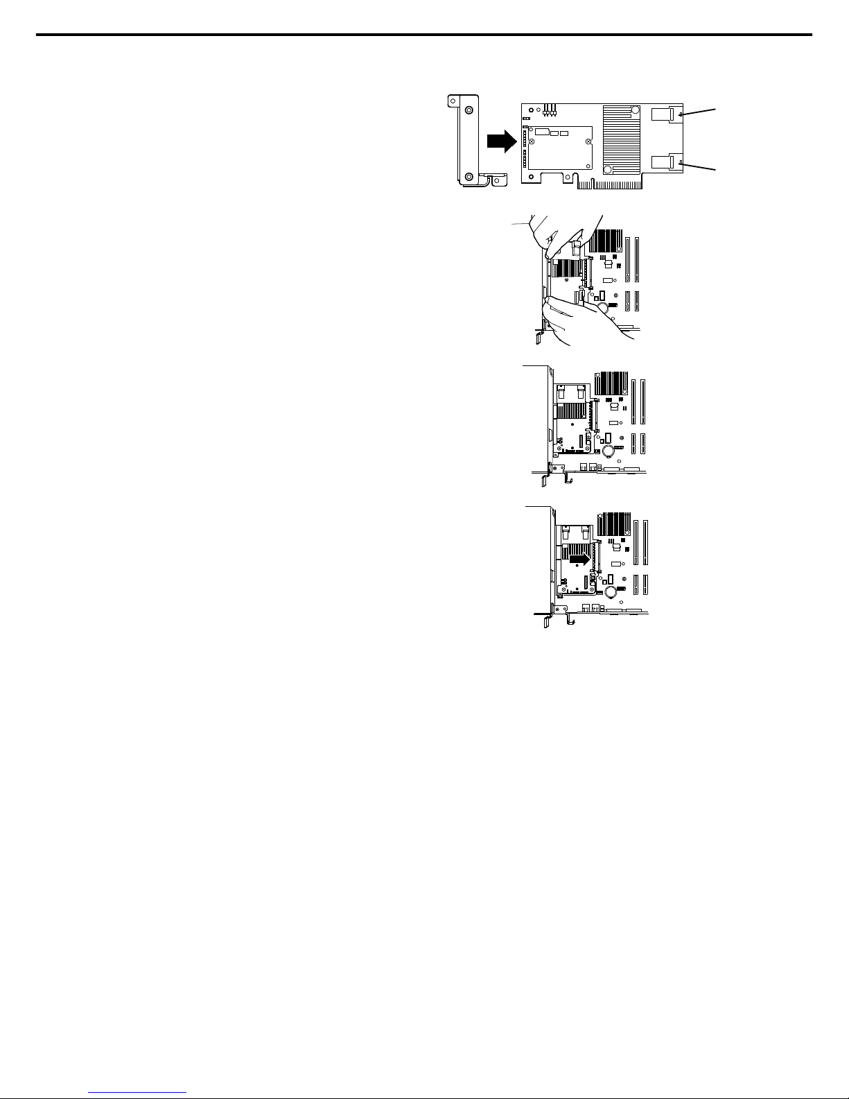
1. Installing Internal Options
Express5800/R120f-1E User’s Guide
88
Chapter 2 Preparations
5. Attach the RAID controller bracket to the
RAID controller with two screws removed in
step 3.
6. Insert the RAID controller sl ightly into the
dedicated slot while ti lting the card.
7. Gently place the RAID controller on bottom
plate of chassis so that it becomes horizontal
to the motherboard.
8. Insert the RAID controller into the slot while
keeping horizontal state.
9. Secure the RAID controller bracket with two screws removed in step 4.
10. Disconnect SAS/SATA cable from SATA connector on motherboard.
11. Perform the following according to the number of hard disk drive connected.
− Four or less hard disk drives are installed:
Connect SAS/SATA cable removed in step 10 to connector (Ports 0-3) on RAID controller.
− Five or more hard disk drives are inst alled:
Connect SAS/SATA cable removed in Step 10 to connect or (Ports 0-3) on RAID controller.
Connect SAS/SATA cable provided with the server to connector (Ports 4-7) on RAID controller.
Remove one scr ew from server chassi s, and remove battery tray for RAID controller.
Connect another end of SAS/SATA cable that has been connected to connector (Ports 4-7) on
RAID controller, to the connector on backplane.
Secure the battery tray for RAID controller with one screw.
12. Continue to install or remove internal options, mount and connect the server, and turn it on.
(2)
Using optional RAID controller (N8103-179)
See Chapter 2 (1.10.4 Installing FBU).
Ports 4-7
Ports 0-3
Page 89
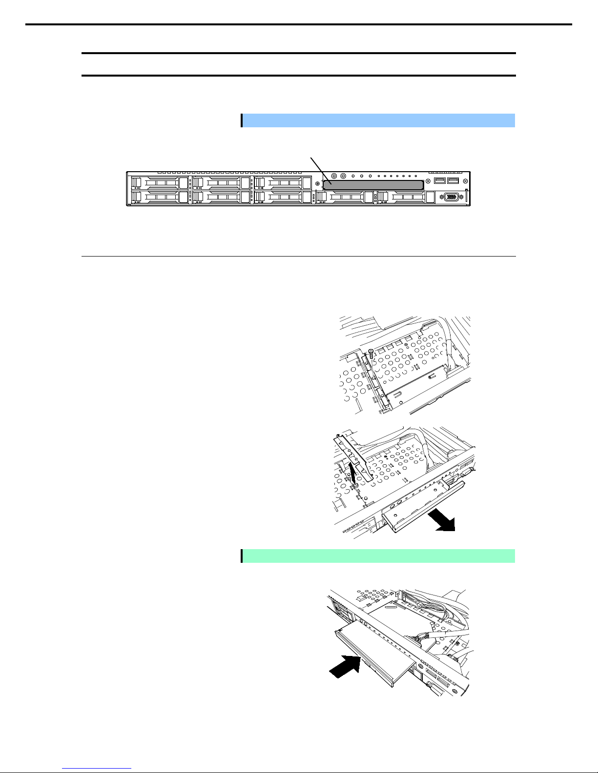
1. Installing Internal Options
Express5800/R120f-1E User’s Guide
89
Chapter 2 Preparations
1.13
Optical Disk Drive
This section describes the procedure for installing the optional optical disk drive.
Important Do not install any unsupported o ptical disk drive.
1.13.1
Installation
Install an optical disk drive in the following procedure.
1. See steps 1 to 6 in Chapter 2 (1.3 Overview of Installation and Removal) for preparations.
2. Remove one screw from the bracket, and
remove the bracket.
3. Remove the dummy cover.
Note
Keep the removed dummy cover for future use.
4. Insert the optical disk drive.
Optical disk drive bay
Page 90

1. Installing Internal Options
Express5800/R120f-1E User’s Guide
90
Chapter 2 Preparations
5. Put the optical disk drive on the tray.
6. Secure the bracket to optical disk drive with
one screw removed in step 2.
7. Connect a cable to the optical disk drive.
1.13.2
Removal
To remove an optical disk drive, reverse the installation procedure above.
Screw
Page 91

1. Installing Internal Options
Express5800/R120f-1E User’s Guide
91
Chapter 2 Preparations
1.14
Use of Internal Hard Disk Drives in the RAID System
This section describes how to use the internal hard disk drives in the RAID system.
Important
If you use hard disk drives in the RAID s
ystem or change the RAID level,
hard disk drives are initialized. If the hard disk drive contains valuable data,
be sure to backup the hard disk drive before installing the RAID controller
and configuring the RAID system.
Tips
• Logic al drives can be created even wit h only one physical device.
• When using SAS hard disk drive, SAS SSD, or SATA SSD, it must be
connect ed to RAID controller.
1.14.1
Connecting cables
See the figures below for how to connect cables.
Using optional RAID controller (1 to 8 hard disk drives)
Optional RAID Controller
Backplan e
Hard Disk Drive
Ports 0-3 SATA 0 -3
SLOT 0
SLOT 1
SLOT 2
SLOT 3
Ports 4-7 SATA 4 -7
SLOT 4
SLOT 5
SLOT 6
SLOT 7
Ports 4-7
Ports 0-3
SATA0-3
SATA4-7
Page 92

1. Installing Internal Opt ions
Express5800/R120f-1E User’s Guide
92
Chapter 2 Preparations
1.14.2
Notes on building RAID system
Note the following points when building a RAID system.
• The number of hard disk drives required varies in each RAID level.
• If the optional RAID controller N8103-176 is used, the RAI D system cannot be built in
RAID5/RAID6/RAID50/RAID60.
RAID level
The minimum number of hard disk drives
N8103-176 N8103-177/178
RAID 0 1 1
RAID 1 2 2
RAID 5 3
RAID 6 3
RAID 10 4 4
RAID 50 6
RAID 60 6
• In the RAID syst em , all the hard disk drives in an array group must have the sam e capacity, interface type,
and rotational speed.
• EXPRESSBUILDER helps you to install the OS to a RAID array easily.
• If you want to install the OS manually, use RAID Configurat ion Utility at POST (Ctrl-R or H). For details,
see Chapter 2 (4. RAID System Configuration) in "Maintenance Guide" or the manual provided with the
optional RAID controller (N8103-176/177/178).
Important
• Do not change the mode to hibernat e while building a RAID syst em.
• Build a disk array in the RAID system using hard disk drives that have the
same specifications (capacity, rotati onal speed, and standard).
Page 93

1. Installing Internal Options
Express5800/R120f-1E User’s Guide
93
Chapter 2 Preparations
1.15
Installing Top Cover
When all internal options are inst alled, close the server with Top Cover.
1. Put Top Cover straight on the server chassis so that it can be surely engaged with the chassis frame.
2. Slide Top Cover toward the front of the server.
3. Tighten Cap Screw on rear of the server.
Page 94

1. Installing Internal Options
Express5800/R120f-1E User’s Guide
94
Chapter 2 Preparations
1.16
Hard Disk Drive
Bays for hard disk drives are provi ded at the front of the server.
A hard disk drive mounted in a dedicated drive tray can be purchased. Inst all the hard disk drive on the server
with it mounted in the drive tray.
Important
Use hard disk drives specified by NEC. Installing a third-par ty hard disk
drive mig ht cause a fai lure of the server as well as the hard disk drive.
Note the following precautions to install hard disk dri ves.
• For onboard connection, hard disk drives having different capacities, types, or rotational speeds cannot
be installed together.
• In the RAID system, all the hard disk drives in an array group must have the same capaci ty, type, and
rotational speed.
• If using hard disk drives in a RAID system, jumper settings or a change of cables may be required.
Bays can contai n up to eight hard disk drives.
Unique slot numbers have been assigned to each slot.
Slot 0
Slot 2
Slot 4
Slot 1
Slot 3
Slot 5
Slot 6
Slot 7
Page 95

1. Installing Internal Options
Express5800/R120f-1E User’s Guide
95
Chapter 2 Preparations
1.16.1
Installation
Install a hard disk drive by using the following procedure.
Note
In the RAID system, use hard disk drives that have the same sp ecifi cations
(capacit y, rotational speed, and standard) for each disk array.
1. See Chapter 2 (1.3 Overview of Installation and Removal) for preparations.
2. Locate the slot where you install the hard disk drive.
The server has eight slots. Install hard disk drives in ascending order of sl ot number.
3. Remove the dummy tray.
Dummy trays are inst alled in every slot as
standard.
Note
Keep the removed dummy trays for future use.
4. Unlock the handle of the tray.
5. Hold the tray firmly and insert it into the slot.
Note
• Push it all the way until the handle’s lock touches the frame.
• H ol d t he tray firmly with both hands.
Page 96

1. Installing Internal Options
Express5800/R120f-1E User’s Guide
96
Chapter 2 Preparations
6. Slowly cl ose the handle.
The tray is locked making a clicking sound.
Note
When you push t he drive into the slot, c onfirm the handle got hooked on the
frame.
7. Run BIOS Setup Utility, and then specify the boot order from Boot menu.
For details, see Chapter 2 (1. System BIOS) in "Maintenance Guide"
Tips
The saved boot order is cleared when a hard disk drive is added.
1.16.2
Removal
To remove hard disk drive, reverse the installation procedure.
If you transf er or dispose of the removed hard disk drive, see Chapter 1 (1. Transfer, Relocation, and Disposal)
in “Maintenance Guide” to erase data.
Important
NEC assumes no liability for data leakage should the product be
transferred to a third p arty without erasing the data.
Note
• If you remove a hard disk drive due to a failur e, check the slot with its
DISK LED 2 lit in amber.
• D o n ot hold handle to pull t he drive out. Doing s o may damag e the handle.
Run the BIOS Setup Utility, and then specify the boot order from Boot menu.
For details, see Chapter 2 (1. System BIOS) in "Maintenance Guide".
Tips
The saved boot order is cleared when a hard disk drive is added.
DISK LED 2
DISK LED 1
Page 97

1. Installing Internal Options
Express5800/R120f-1E User’s Guide
97
Chapter 2 Preparations
1.16.3
Replacing a hard disk drive in the RAID system (Auto Rebuild)
In the RAID system, you can use the auto rebuild feature to restore dat a back to the state before a failure
occurred.
The auto rebuild feature is enabled in logical drives set to RAID 1, RAID 5, RAID 6, RAID 10, RAID 50, and
RAID60.
The disk array is automatically rebuilt when hot swapping (replacing a hard disk drive while the power on) a
failed hard disk drive.
During the auto rebuild, DISK LEDs 1 and 2 on the hard disk drive blink green and amber respectively to
indicate that the auto rebuild i s being performed.
Observe the following precautions whenever executing the auto rebuild.
• Do not turn off the server until the auto build completes after a hard disk drive fails.
• Leave an interval of at least 90 seconds between a hard disk drive removal and a hard disk drive
installation.
• Do not replace a disk during the auto rebuilding of another hard disk drive (during an auto rebuild, DISK
LEDs 1 and 2 on the hard disk drive blink green and amber resp ectively).
Page 98

1. Installing Internal Options
Express5800/R120f-1E User’s Guide
98
Chapter 2 Preparations
1.17
Power Supply Unit
This server can co ntain two power supply units. The server provides a redundant power configuration that
ensures continued operation of the system in the unlikely event one of the power supply units fails.
Tips
AC power supply unit has a c able tie to prevent AC cable from slipping out.
1.17.1
Cold redundant feature
The server supports the feature to optimize power effici ency as described below:
• Cold redundant feature can run the system with optimum power efficiency by raising operating efficiency
of primary power supply unit and lowering that of redundant power supply unit in redundant power
configuration.
• If power efficiency of power units is not optimized due to system configuration, this feature is disabled
automatically.
Cold redundant feature can be used under the following conditions:
• Two power supply units must be installed for redundant configuration.
• See Chapter 2 (1. System BIOS) in "Maintenance Guide", change parameters as shown below, save the
settings and exit from SETUP.
Server → Power Control Configuration → Cold Redundant Mode → Enabled
Run SETUP again, and check if the status of Cold Redundant Mode shows Enabled in Server m enu.
Page 99

1. Installing Internal Options
Express5800/R120f-1E User’s Guide
99
Chapter 2 Preparations
1.17.2
Installation
Follow the steps below to install a power supply unit:
1. See steps 1 to 4 in Chapter 2 (1.3 Overview of Installation and Removal) for preparations.
2. Remove the blank cover.
Note
Keep the removed blank cover for fut ure us e.
3. Insert the power supply unit until it is locked with clicking sound.
4. Connect the power cords.
Power supply unit
#2
Power cord for power
supply unit 2
Power supply unit
#1
Power cord for power
supply unit 1
Slot for additional
power supply unit
Slot for standard
power supply unit
REAR
Page 100
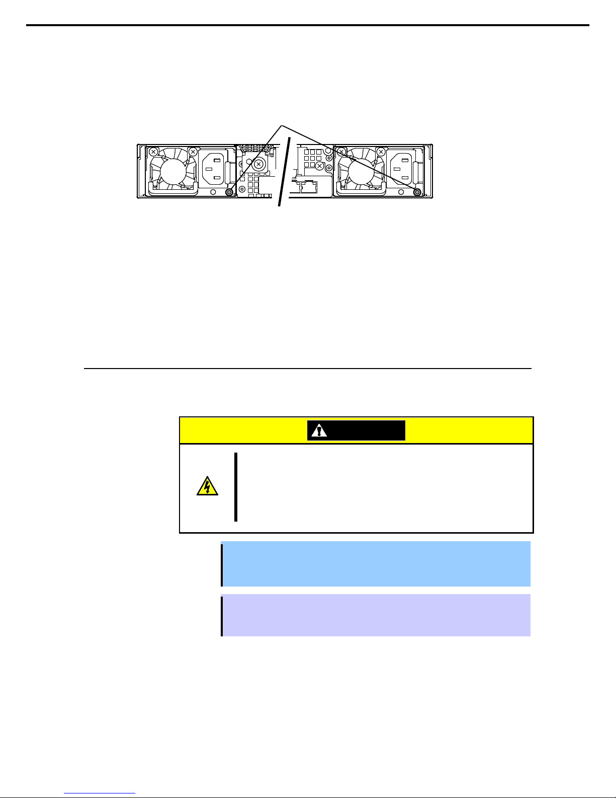
1. Installing Internal Options
Express5800/R120f-1E User’s Guide
100
Chapter 2 Preparations
AC POWER LED blinks green when the power cord is connected to either of power supply units and
the other power supply unit’s AC POWER LED goes on amber.
When the power cord is connected to it, AC POWER LEDs on both power supply units blink green.
5. Power on the server.
AC POWER LEDs go on green.
6. Confirm, by STATUS LED or on POST screen, that there are no errors related to the power supply
units.
See Chapter 3 (1. POST Error Message) in “Maintenance Guide” for details on POST error m essages.
If AC POWER LEDs are off, reinstall the power supply units. If the same error occurs, contact with your
sales representative.
1.17.3
Replacing a failed power supply unit
Replace only when the power supply unit fails.
To remove power supply unit, reverse the installation procedure.
CAUTION
Be sure to observe the follo wing pr ecautions to use the server safely. Fail ure to
observe the precaution s may cause burns, injury, and property damage. For
details, see Safety Precautions and Regulatory Notice s.
• Pay attent ion to electric hazard.
Important
• Do not remove a power supply unit operating normally.
• To maintain the cooling effect in the server, be sure to install the blank cover in
the vacant slot.
Tips
In the redundant power configuration (with two power supply units) and if either one of
power supply units fails, the failing power supply unit can be replaced with the system
power on.
Install the new power supply unit taking steps 3 to 6 of "Installation", and confirm that the power supply unit is
installed normally.
AC POWER LED
Power supply unit #1
Power supply unit #2
 Loading...