

Page 1

ND-70428 (E)
ISSUE 1
STOCK # 200892
®
Message Center Interface (MCI)
Specifications
JANUARY, 1999
NEC America, Inc.
Page 2

LIABILI TY D ISC LAIMER
NEC America, Inc. reserves the right t o change t he specifications,
functions, or features, at any time, without notice.
NEC America, Inc. has prepared this docum ent for use by its employees and customers. The information contained herein is the
property of NEC America, Inc. and shall not be reproduced without
prior written approval from NEC America, Inc.
NEAX and D
term
are registered trademarks of NEC Corporation.
Copyright 1999
NEC America, Inc.
Printed in U S A
Page 3

ND-70 428 (E)
ISSUE 1
JANUARY, 1999
NEAX2400 IMX
Message Center Interface (MCI) Specifications
TABLE OF CONTENTS
Page
LIST OF FIGURES . . . . . . . . . . . . . . . . . . . . . . . . . . . . . . . . . . . . . . . . . . . . . . . . . . . . . . . . . . . . . . . . . . . . . . . ii
LIST OF TABLES. . . . . . . . . . . . . . . . . . . . . . . . . . . . . . . . . . . . . . . . . . . . . . . . . . . . . . . . . . . . . . . . . . . . . . . . . iii
CHAPTER 1 INTRODUCTION . . . . . . . . . . . . . . . . . . . . . . . . . . . . . . . . . . . . . . . . . . . . . . . . . . . . . . . . . . 1
CHAPTER 2 MCI FOR IOC . . . . . . . . . . . . . . . . . . . . . . . . . . . . . . . . . . . . . . . . . . . . . . . . . . . . . . . . . . . . . 3
1. SPECIFICATIONS . . . . . . . . . . . . . . . . . . . . . . . . . . . . . . . . . . . . . . . . . . . . . . . . . . . . . . . . . . . . . . . 3
1.1 Interface . . . . . . . . . . . . . . . . . . . . . . . . . . . . . . . . . . . . . . . . . . . . . . . . . . . . . . . . . . . . . . . . . 3
1.2 Text Format. . . . . . . . . . . . . . . . . . . . . . . . . . . . . . . . . . . . . . . . . . . . . . . . . . . . . . . . . . . . . . . 3
2. PROTOCOL AND MESSAGE RESPONSES. . . . . . . . . . . . . . . . . . . . . . . . . . . . . . . . . . . . . . . . . . . 4
2.1 PBX → MC . . . . . . . . . . . . . . . . . . . . . . . . . . . . . . . . . . . . . . . . . . . . . . . . . . . . . . . . . . . . . . . 4
2.2 MC → PBX . . . . . . . . . . . . . . . . . . . . . . . . . . . . . . . . . . . . . . . . . . . . . . . . . . . . . . . . . . . . . . . 4
CHAPTER 3 MCI FOR LAN . . . . . . . . . . . . . . . . . . . . . . . . . . . . . . . . . . . . . . . . . . . . . . . . . . . . . . . . . . . . 5
1. SPECIFICATIONS . . . . . . . . . . . . . . . . . . . . . . . . . . . . . . . . . . . . . . . . . . . . . . . . . . . . . . . . . . . . . . . 5
1.1 Timing . . . . . . . . . . . . . . . . . . . . . . . . . . . . . . . . . . . . . . . . . . . . . . . . . . . . . . . . . . . . . . . . . . . 5
1.2 Interface . . . . . . . . . . . . . . . . . . . . . . . . . . . . . . . . . . . . . . . . . . . . . . . . . . . . . . . . . . . . . . . . . 5
1.3 Basic Configuration of Text. . . . . . . . . . . . . . . . . . . . . . . . . . . . . . . . . . . . . . . . . . . . . . . . . . . 6
1.4 Text Format. . . . . . . . . . . . . . . . . . . . . . . . . . . . . . . . . . . . . . . . . . . . . . . . . . . . . . . . . . . . . . . 9
2. PROTOCOL AND MESSAGE RESPONSES. . . . . . . . . . . . . . . . . . . . . . . . . . . . . . . . . . . . . . . . . . . 13
2.1 Link Establishment Sequence. . . . . . . . . . . . . . . . . . . . . . . . . . . . . . . . . . . . . . . . . . . . . . . . . 13
2.2 Transmission and Reception of Call Information . . . . . . . . . . . . . . . . . . . . . . . . . . . . . . . . . . 14
2.3 MWL Control. . . . . . . . . . . . . . . . . . . . . . . . . . . . . . . . . . . . . . . . . . . . . . . . . . . . . . . . . . . . . . 19
2.4 Monitoring Status Between Client and Server . . . . . . . . . . . . . . . . . . . . . . . . . . . . . . . . . . . . 23
2.5 Link Release Sequence . . . . . . . . . . . . . . . . . . . . . . . . . . . . . . . . . . . . . . . . . . . . . . . . . . . . . 24
2.6 Connection Sequence for System Changeov er . . . . . . . . . . . . . . . . . . . . . . . . . . . . . . . . . . . 25
CHAPTER 4 MESSAGE FORMAT . . . . . . . . . . . . . . . . . . . . . . . . . . . . . . . . . . . . . . . . . . . . . . . . . . . . . . . 27
1. ICS FORMAT . . . . . . . . . . . . . . . . . . . . . . . . . . . . . . . . . . . . . . . . . . . . . . . . . . . . . . . . . . . . . . . . . . . 27
2. IMX FORMAT . . . . . . . . . . . . . . . . . . . . . . . . . . . . . . . . . . . . . . . . . . . . . . . . . . . . . . . . . . . . . . . . . . . 31
CHAPTER 5 SERVICE CONDITIONS . . . . . . . . . . . . . . . . . . . . . . . . . . . . . . . . . . . . . . . . . . . . . . . . . . . . 39
CHAPTER 6 DATA ASSIGNMENT . . . . . . . . . . . . . . . . . . . . . . . . . . . . . . . . . . . . . . . . . . . . . . . . . . . . . . . 41
ND-70428 (E) TABLE OF CONTENTS
Page i
Revision 1.0
Page 4

LIST OF FIGURES
Figure Title
Figure 1-1 MCI for UCD Incoming Call . . . . . . . . . . . . . . . . . . . . . . . . . . . . . . . . . . . . . . . . . . . . . . . . . . . . . 1
Figure 1-2 MC I for Attendant Incoming Call . . . . . . . . . . . . . . . . . . . . . . . . . . . . . . . . . . . . . . . . . . . . . . . . . 1
Figure 2-1 Word Framing Example . . . . . . . . . . . . . . . . . . . . . . . . . . . . . . . . . . . . . . . . . . . . . . . . . . . . . . . . 3
Figure 2-2 Typical Text Format . . . . . . . . . . . . . . . . . . . . . . . . . . . . . . . . . . . . . . . . . . . . . . . . . . . . . . . . . . . 3
Figure 3-1 PBX and MCI for LAN Interface . . . . . . . . . . . . . . . . . . . . . . . . . . . . . . . . . . . . . . . . . . . . . . . . . . 6
Figure 3-2 Text Basic Configuration . . . . . . . . . . . . . . . . . . . . . . . . . . . . . . . . . . . . . . . . . . . . . . . . . . . . . . . 6
Figure 3-3 Lamp Control Text Configuration . . . . . . . . . . . . . . . . . . . . . . . . . . . . . . . . . . . . . . . . . . . . . . . . . 9
Figure 3-4 Call Information Text Configuration . . . . . . . . . . . . . . . . . . . . . . . . . . . . . . . . . . . . . . . . . . . . . . . 9
Figure 3-5 Server Response Text Configuration . . . . . . . . . . . . . . . . . . . . . . . . . . . . . . . . . . . . . . . . . . . . . 10
Figure 3-6 Client Response Text Configuration . . . . . . . . . . . . . . . . . . . . . . . . . . . . . . . . . . . . . . . . . . . . . 11
Figure 3-7 Status Monitoring Text Configuration . . . . . . . . . . . . . . . . . . . . . . . . . . . . . . . . . . . . . . . . . . . . . 11
Figure 3-8 Link Release Text Configuration . . . . . . . . . . . . . . . . . . . . . . . . . . . . . . . . . . . . . . . . . . . . . . . . 12
Figure 3-9 Link E stablis hme nt Sequence . . . . . . . . . . . . . . . . . . . . . . . . . . . . . . . . . . . . . . . . . . . . . . . . . . 13
Figure 3-10 Transmission and Reception of Call Information Sequence . . . . . . . . . . . . . . . . . . . . . . . . . . . 14
Figure 3-11 Transmission and Reception of Call Information Error Processing Sequence (1) . . . . . . . . . . . 15
Figure 3-12 Transmission and Reception of Call Information Error Processing Sequence (2) . . . . . . . . . . . 16
Figure 3-13 Transmission and Reception of Call Information Error Processing Sequence (3) . . . . . . . . . . . 17
Figure 3-14 Transmission and Reception of Call Information Error Processing Sequence (4) . . . . . . . . . . . 18
Figure 3-15 MWL Control Processing Sequence . . . . . . . . . . . . . . . . . . . . . . . . . . . . . . . . . . . . . . . . . . . . . 19
Figure 3-16 MWL Control Error Processing Sequence (1) . . . . . . . . . . . . . . . . . . . . . . . . . . . . . . . . . . . . . . 20
Figure 3-17 MWL Control Error Processing Sequence (2) . . . . . . . . . . . . . . . . . . . . . . . . . . . . . . . . . . . . . . 21
Figure 3-18 MWL Control Error Processing Sequence (3) . . . . . . . . . . . . . . . . . . . . . . . . . . . . . . . . . . . . . . 22
Figure 3-19 Monitoring Status Between Client and Server Processing Sequence . . . . . . . . . . . . . . . . . . . . 23
Figure 3-20 Link Release Sequence . . . . . . . . . . . . . . . . . . . . . . . . . . . . . . . . . . . . . . . . . . . . . . . . . . . . . . . 24
Figure 3-21 System Changeover Connection Sequence . . . . . . . . . . . . . . . . . . . . . . . . . . . . . . . . . . . . . . . 25
Page
LIST OF FIGURES
Page ii
Revision 1.0
ND-70428 (E)
Page 5

LIST OF T ABLE S
T able Title
Table 4-1 Call Type Codes for Attendant Incoming Calls . . . . . . . . . . . . . . . . . . . . . . . . . . . . . . . . . . . . . 29
Table 4-2 Call Type Codes for UCD Incoming Calls . . . . . . . . . . . . . . . . . . . . . . . . . . . . . . . . . . . . . . . . . 29
Table 4-3 Message Text Station Number Explanation . . . . . . . . . . . . . . . . . . . . . . . . . . . . . . . . . . . . . . . . 30
Table 4-4 PBX → MC Data Type Explanation . . . . . . . . . . . . . . . . . . . . . . . . . . . . . . . . . . . . . . . . . . . . . . 31
Table 4-5 Call Type Codes for Attendant Incoming Calls . . . . . . . . . . . . . . . . . . . . . . . . . . . . . . . . . . . . . 34
Table 4-6 Call Type Codes for UCD Incoming Calls . . . . . . . . . . . . . . . . . . . . . . . . . . . . . . . . . . . . . . . . . 34
Table 4-7 MC → PBX Data Type Explanation . . . . . . . . . . . . . . . . . . . . . . . . . . . . . . . . . . . . . . . . . . . . . . 35
Table 4-8 MC → PBX Data Type Explanation . . . . . . . . . . . . . . . . . . . . . . . . . . . . . . . . . . . . . . . . . . . . . . 37
Page
ND-70428 (E)
LIST OF T ABLE S
Page iii
Revision 1.0
Page 6

This page is for your notes.
LIST OF TABLES
Page iv
Revision 1.0
ND-70428 (E)
Page 7

CHAPTER 1 INTRODUCTION
This manual provides the Message Center Interface (MCI) specifications for the NEAX2400 IMX system.
When a call terminates to the attendant or a Uniform Call Distribution (UCD) station, the call information is
sent via the MCI to the Messa ge Center (MC). Base d on the call informa tion fr om the Privat e Branch Exchange
(PBX), the MC achieves ON/OFF control of the Message Waiting Lamp (MWL) and Message Waiting (MW)
indication of the station. Figure 1-1 and Figure 1-2 show the MCI for a UCD incoming call and an attendant
incoming call.
PBX
UCD
MC
ex. Voice
Message S y stem
IOC/
LANI
Message Center Interface (RS-232C/LAN)
Note:
Figure 1-1 MCI for UCD Incoming Call
PBX
IOC/
LANI
Message C enter Interfac e (RS-23 2C/LAN)
ATT
CRT
MC
For detailed information on an external device used as MC, refer to the manual included
with the external de v ice.
Figure 1-2 MCI for Attendant Incoming Call
ND-70428 (E) CHAPTER 1
Page 1
Revision 1.0
Page 8

This page is for your notes.
CHAPTER 1 ND-70428 (E)
Page 2
Revision 1.0
Page 9

CHAPTER 2 MCI FOR IOC
1. SPECIFICATIONS
1.1 Interface
This section has information on the signal interface requirements for the MCI for Input/Output Controller
(IOC).
Operating mode : Full duplex
Electrical interface characteristic : RS-232C electrical interface standard
Frame code : US ASCII
Parity : Non/Odd/Even
Word framing example : See Figure 2-1.
Data rate : Up to 9600 bps
Priority sequence
• Primary sta tion : PBX
• Secondary station : MC
Parity BitStart Bit
b1 b2 b3 b4 b5 b6 b7 b8
Figure 2-1 W or d Framing Example
1.2 Text Format
MCI for IOC uses the following text format.
S
S
T
X
STX : Start of Text
SA : System Addr ess
UA : Unit Address
EI : Entry Index
ETX : End of Text
U
A
A
Data Bits
E
I
Message text
(Refer to CHAPTER 4.)
Stop Bits
E
T
X
Figure 2-2 Typical Text Format
ND-70428 (E) CHAPTER 2
Page 3
Revision 1.0
Page 10

MCI FOR IOC
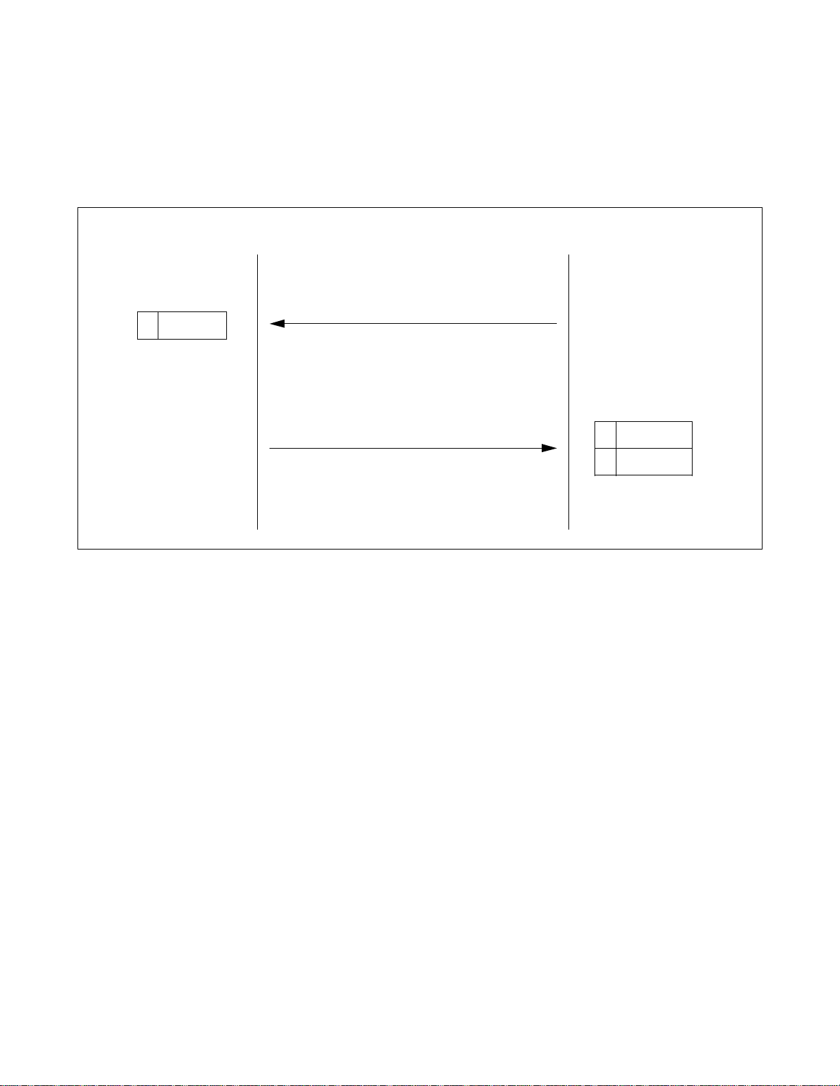
2. PROTOCOL AND ME SSAGE RESPONSES
This section has inf ormation on protocol and m es sage responses of MCI for IOC. For detailed information on
each message, refer to CHAPTER 4.
2.1 PBX
→
PBX
Note:
MC
MC
S
SAU
T
X
receive receive
send send
S
E
Data Data
A
T
X
t
Note
SAU
T
X
A
E
T
X
The interval between communications is the Guard Timing (GT) value programmed in
ASYD (SYS1, Index 28, Bits 0-4).
2.2 MC
→
PBX
(1) W h en receiving messages con tr olling one station, the follo wing text format applies.
MC
PBX
S
SAU
T
X
A
send
STA1
E
T
X
receive
350 ms or longer
S
SAU
T
X
A
send
STA1
E
T
X
receive
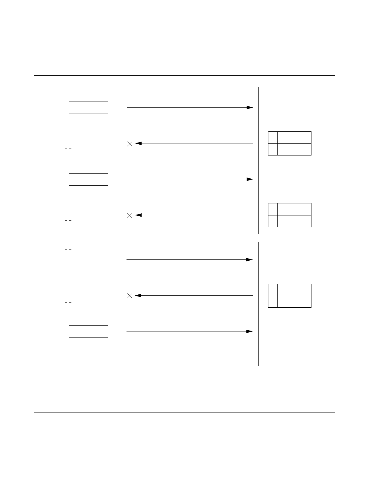
(2) When receiving queue is full, the PBX sends Call Type 39. This requests MC to stop transmission. Whe n
the PBX has processed all MWL requests in full queue, the PBX sends Call Type 66. This requests MC
to start sending MWL data.
message messag e message
MC
PBX
MC
PBX
send
receive receive receive
wait
receive
send
Call Type 66
(Start Sending MW Control Data)
send
(Stop Sending MW Control Data)
receive
CHAPTER 2 ND-70428 (E)
Page 4
Revision 1.0
receivesend send
send
Call Type 39
wait
Page 11

CHAPTER 3 MCI FOR LAN
1. SPECIFICATIONS
1.1 Timing
Timing to Esta blish a Link : A link is connected when an MC connect request is received.
Timing to Output Call Information : When a call terminates to the att endant or a UCD group station,
Timing to Rec eive MWL Information : When Message Waiting Lamp (MWL) information is received,
Timing to Release the Link : The MC for Local Area Network (LAN), which is a client of
the call information is sent via the MCI to the MC.
the MWL of the st ation served by the PBX is cause d to be ON/
OFF.
the PBX, discards the socket and performs processing to release the link when it does not receive a “Call Information
Text” or “Server Response Text” in a given time interval from
the server. When the PBX or the server does not receive a
“Lamp Control Text”, “Client Response Te xt”, or “Status Monitoring Text” in a gi ven tim e interv al from the c lient, it p erforms
NG processing + sends a “Connection Disconnect Text” and
then discards the socket and performs processing to release the
link.
1.2 Interface
This section has information on the interface requirements for the PBX and the external device (MC for
LAN). Figure 3-1 shows the PBX and the MCI for LAN interface.
Protocol : Stream type socket (TCP) protocol
Physical conditi on : Ethernet
Software condit ions
• PBX : Socket interface (capability provided to deal with WinSock)
• External device : Shall use the WinSock, UNIX socket and other libraries.
Port No. : 60020 (defined at PBX side)
Codes to be used
• Transmis sion code : ASCII 8 bits without parity
• Control codes
SYN : 16H indicates the beginning of a text.
STX : 02H indicate s the beginning of an MCI record.
ETX : 03H indicates the end of an MCI record.
ND-70428 (E) CHAPTER 3
Page 5
Revision 1.0
Page 12

MCI FOR LAN
PBX
Application
Call information/MWL
informa tio n tr a ns fer
protocol
Socket
TCP/IP
Ethernet
Call informat ion/MWL
info rmation protocol
External Device (MC for LAN)
Applic ation
Call information /M WL
information transfer
protocol
Socket
TCP/IP
Ethernet
Figure 3-1 PBX and MCI for LAN Interface
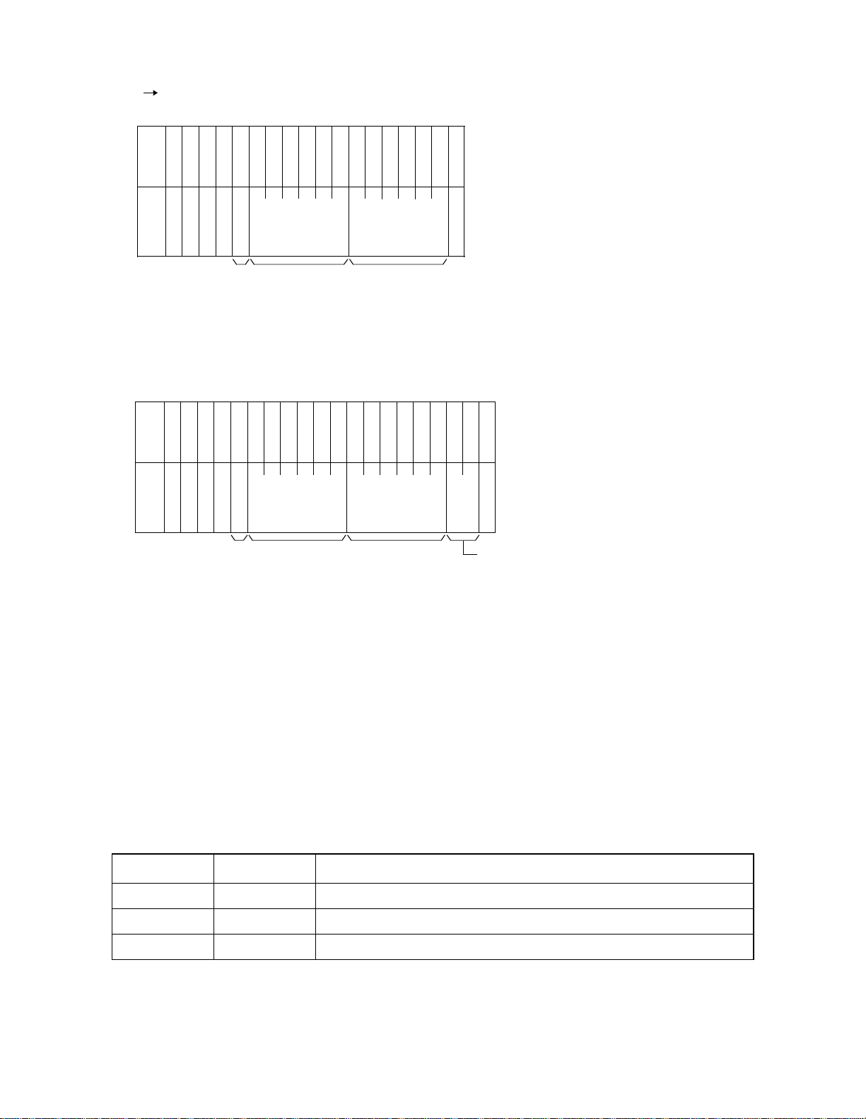
1.3 Basic Configuration of Text
Data is transferred between the se rver and cl i ent in the unit of a text.
A text, as shown in Figure 3-2, consists of SYN (16H), used as the beginning of a text, a text identifier,
data length, device No., sequence No., message and parity (horiz ontal parity check system).
The result of the exclusive logical sum of the parity r ange is set as the parity.
(If the resu lt of t h e exclus ive logical sum of the range from the text identifier to the parity is even parity,
the check bit is set to “0”. If it is odd parity, the check bit is set to “1”.)
S
(X)
Y
N
Text
identifier
(X)
Data length
(XXX)
Device
Sequence
No.
(XX)
Parity Range
No.
(XX)
Figure 3-2 Text Basic Configuration
(1) SYN: Text Data Start Position Information
The SYN defines the posit ion where the text data to be sent or recei ved is to start.
Data type : Hexadecimal
Data size : 1 byte
Data : SYN 16H
CHAPTER 3 ND-70428 (E)
Page 6
Revision 1.0
Call information or
lamp control
informa tio n or
response No., et c.
Parity
(X)
Page 13

(2) Text Identifier
The text identifier identifies the data to be sent or received.
Data type : Decimal (ASCII code)
Data size : 1 digit
Data range: 0 to 9
0 : Not used
1 : Lamp Control Text (MC for LAN PBX)
The PBX that recei ve d the da ta sends the result of t he received data ch eck as a “Serv er
Response Text (t ext identif ier (3))” to the MC for LAN in a predetermined time inte rval.
2 : Call Information Text (PBX MC for LAN)
The MC for LAN that received the data sends the result of the received data check as
a “Client Response Text (text identifier (4))” to the PBX in a predetermined time interval.
3 : Server Response Text (PBX MC for LAN)
MCI FOR LAN
When the PBX receives identifiers (1) or (5), it sends the result of the received data
check to the MC for LAN.
4 : Client Response Text (MC for LAN PBX)
When the MC for LAN receives ident ifier (2), it se nds the re sult of the received data
check to the PBX.
5 : Status Monitoring Text (MC for LAN PBX)
When both the MC for LAN and PBX do not send any of the v ar ious types of processing requests, a status monitoring text is sent by the MC for LANs in a predetermined
time interval.
When the PBX receives the text, it monitors the status of the client.
6 : L ink Re le ase Text (MC for LAN PBX)
A link release request text sent from the client to the server and from the server to the
client.
(3) D at a Len g th
The data length indicates the leng th of data to be sent and received betwee n the server and client.
The number of bytes ranging from the character following the data length to the character preceding to
the parity is set in terms of 3 digits.
Data type : Decimal (ASCII code)
Data size : 3 digits
Data range: 0 to 999
ND-70428 (E) CHAPTER 3
Page 7
Revision 1.0
Page 14

MCI FOR LAN
(4) D evice N o.
The device No. indicates the device No. for the MC for LAN connected to the server.
The MC for LAN sends its own device No. to the server, and the PBX sends the device No. for the MC
for LAN, which is the destination of the text.
The device No. to be used is defined at the PBX side.
(5) Sequence No.
The sequence No. is a serial number for the data to be sent.
It is a number assigned to assure that the transferred data is cleared.
The PBX and server manage independent numbers respectively.
Data type : Decimal (ASCII code)
Data size : 2 digits
Data range: 0 to 99
Data type : Decimal (ASCII code)
Data size : 2 digits
Data range: 0 to 99
(6) Parity
The horizontal parity chec k method is a dopted. The c alculation range is f rom the te xt ide ntifie r to the c haracter preceding to the parity . By default, odd parity is used.
The parity check method can be changed in system data.
Data type : Hexadecimal
Data size : 1 byte
Data range: 00H to FFH
CHAPTER 3 ND-70428 (E)
Page 8
Revision 1.0
Page 15

MCI FOR LAN
1.4Text Format
(1)Lamp Control Text (MC for LAN PBX)
Figure 3-3 shows text to be sent when a request for control from the MC for LAN is presented. The format
in a record is the IMX format of MCI message. It complies with the format of MC PBX message in
CHAPTER 4, Section 2, IMX FORMAT.
∫ ∫
S
(X)
Y
N
Text
identifier
(1)
Data length
(XXX)
Device
No.
(XX)
Sequence
No.
(XX)
New control
Parity
(X)
∫ ∫
Field of a record
Figure 3-3 Lamp Control Text Configuration
(2)Call Information Text (MC for LAN PBX)
Figure 3-4 shows the call information text to be sent from the PBX to the MC for LAN. The format in a
record is the IMX format of MCI message. It complies with the format of PBX MC message in CHAP-
TER 4, Section 2, IMX FORMAT.
As for text identifier (2), a piece of call information is created when a call terminates to the attendant or a
UCD station and when text is sent to the MC for LAN. Therefore, each text contains one record.
∫ ∫
S
(X)
Y
N
Text
identifier
(2)
Data length
(XXX)
Device
No.
(XX)
Sequence
No.
(XX)
Call information
∫ ∫
Field of a record
Figure 3-4 Call Information Text Configuration
ND-70428 (E) CHAPTER 3
Parity
(X)
Page 9
Revision 1.0
Page 16

MCI FOR LAN
(3) Server Response Text (MC for LAN P BX)
Figure 3-5 shows the server response text to be sent by the PBX that received text identifiers (1) and (5)
to notify the MC whether or not the received text is correct.
Response No. (server information)
Data type : Decimal (ASCII code)
Data size : 1 digit
Data range: 0 to 9
0 : Normal
1 : Received text parity error
2 : Device No. not defined
3 : Received text erro r (inco r rect text received)
4 to 9 : Not used
S
(X)
Y
N
Text
identifier
(3)
Data leng th
(005)
Device
No.
(XX)
Sequence
No.
(XX)
Response
No.
(X)
Parity
(X)
Figure 3-5 Server Response Text Configuration
(4) Client Response Text (MC for LAN PBX)
Figure 3-6 sh ows the client response te xt to be sent by the MC for LAN that recei ved text identifie r (2) to
notify the PBX whether or not the received text is correct.
Response No. (client side information)
Data type : Decimal (ASCII code)
Data size : 1 digit
Data range: 0 to 9
0 : Normal
1 : Received text parity error
2 : Not used
3 : Received text erro r (inco r rect text received)
4 to 9 : Not used
CHAPTER 3 ND-70428 (E)
Page 10
Revision 1.0
Page 17

MCI FOR LAN
S
(X)
Y
N
Text
identifier
(4)
Data leng th
(005)
Device
No.
(XX)
Sequence
No.
(XX)
Resp onse
No.
(X)
Parity
(X)
Figure 3-6 Client Response Text Configuration
(5) Status Monitoring Text (MC for LAN PBX)
The text shown in F igure 3-7 is defi ned for use in m onitoring the serve r status from the client a nd the clie nt
status from the se rver. In response to the text, the serve r sends a “Server Response Text (3)” to the client.
Client devic e information
Data type : Decimal (ASCII code)
Data size : 2 digits
Data range: 0 to 99
Data type
00 : Normal
01 to 99 : To be defined at MC side
S
Y
N
(X)
Text
identifier
(5)
Data leng th
(006)
Figure 3-7 Status Monitoring Text Configura ti on
Devi ce
No.
(XX)
Sequence
No.
(XX)
Client
device
infor-
mation
(XX)
Parity
(X)
ND-70428 (E) CHAPTER 3
Page 11
Revision 1.0
Page 18

MCI FOR LAN
(6) L ink Re le ase Text (MC for LAN PBX)
Figure 3-8 shows a link release request to be sent from the client to the server and from the server to the
client. Processing is performed to release the link immediately afte r the text is recei ved.
S
(X)
Y
N
Text
identifier
(6)
Data length
(004)
Device
No.
(XX)
Sequence
No.
(XX)
Figure 3-8 Link Release T ext Configuration
Parity
(X)
CHAPTER 3 ND-70428 (E)
Page 12
Revision 1.0
Page 19

2. PROTOCOL AND ME SSAGE RESPONSES
2.1 Link Estab lishment Se q u en ce
Figure 3-9 sho ws the sequence used when the client reques ts the server to establish a link.
Client (MC for LAN) Server (PBX)
Connection request (CONNECT)
Connection accepted (ACCEPT)
MCI FOR LAN
System equipment OK
500Text identifier
Response No.
Note
Note:
The client sends a status monitoring text immediately after a link is established.
Status monitori ng
Server response text
Figure 3-9 Link Establishment Sequence
3*Text identifier
Response No.
ND-70428 (E) CHAPTER 3
Page 13
Revision 1.0
Page 20

MCI FOR LAN
2.2 Tra nsmission and Reception of Call Inform at ion
(1) Normal Processing Sequence for Transmission and Reception of Call Information
Figure 3-10 shows the normal sequence used when the server sends call information to the client.
Client (MC for LAN) Server (PBX)
Received data check
40Text identifier
Response No.
Figure 3-10 Transmission and Reception of Call Information Sequence
Call information
Received data OK
2Text
CHAPTER 3 ND-70428 (E)
Page 14
Revision 1.0
Page 21

(2)Error Processing Sequence (1) for Transmission and Reception of Call Information
Figure 3-11 shows the error processing sequence used when the server sends call information to the client.
Client (MC for LAN) Server (PBX)
MCI FOR LAN
Received data check
4*Text identifier
Note
Received data check
Note:
Response No.
40Text identifier
Response No.
The * value varies with an error in the received data. (Refer to CHAPTER 3, Section 1.4,
(4) Client Response Text.)
Call information
Received data NG
Call information retransmitted (Same data)
Received data OK
2Text
2Text
Figure 3-11 Transmission and Reception of Call Information Error Processing Sequence (1)
ND-70428 (E) CHAPTER 3
Revision 1.0
Page 15
Page 22

MCI FOR LAN
(3)Error Processing Sequence (2) for Transmission and Reception of Call Information
Figure 3-12 shows the error processing sequence used when the server sends call information to the client.
Client (MC for LAN) Server (PBX)
Received data check
4*Text identifier
Note 1
Received data check
Response No.
4*Text identifier
Response No.
∫ ∫
Call information
Received data NG
Call information retransmitted (Same data)
Received data NG
Call information retransmitted (Same data)
∫ ∫
2Text
2Text
2Text
First time
Second time
Sixth time
Received data check
4*Text identifier
Response No.
Socket discarded
Link released
(Client response text is not
sent.)
Note 1:
The * value varies with an error in the received data. (Refer to CHAPTER 3, Section 1.4,
Received data NG
Link release text
(4) Client Response Text.)
Note 2:
The maximum number of times the same data is sent is 6. When the text checks NG six consecutive
times, the socket is discarded and the link released.
Figure 3-12 Transmission and Reception of Call Information Error Processing Sequence (2)
CHAPTER 3 ND-70428 (E)
Page 16
Revision 1.0
Note 2
6Text
Socket discarded
Link released
Page 23

(4)Error Processing Sequence (3) for Transmission and Reception of Call Information
Figure 3-13 shows the processing sequence used when the server sends call information to the client and
does not receive any client response text.
Client (MC for LAN) Server (PBX)
MCI FOR LAN
Received data check
4*Text identifier
Note 1
Received data check
Received data check
Response No.
4*Text identifier
Response No.
∫ ∫
Call information
Client response text
Call information retransmitted (Same data)
Client response text
Call information retransmitted (Same data)
2Text
First time
No text received
2Text
Second time
No text received
∫ ∫
2Text
Sixth time
T1 timer
T1 timer
T1 timer
4*Text identifier
Response No.
Socket discarded
Link released
(Client response text is not
sent.)
Client response text
Link release text
No text received
6Text
Socket discarded
Link released
T1 : Timer value until the next processing: 10 (S)
Note 1:
The * value varies with an error in the received data. (Refer to CHAPTER 3, Section 1.4,
(4) Client Response Text.)
Note 2:
The maximum number of times the same data is sent is limited to 6. When the text checks NG six
consecutive times, the socket is discarded and the link released.
Figure 3-13 Transmission and Reception of Call Information Error Processing Sequence (3)
ND-70428 (E) CHAPTER 3
Revision 1.0
Note 2
Page 17
Page 24

MCI FOR LAN
(5) Error Processing Sequence (4) for Transmission and Reception of Call Information
Figure 3-14 shows the sequence used when the server sends call information to the client and does not
recei ve an y c lient res ponse te xt o r det ects an error i n the data r eceived by the client ; the s erv er the n re leases the link connected to the smaller numbered MC for LAN and sends call information to the other MC
for LAN.
Client (MC for LAN) Server (PBX)
Received data check
4*Text identifier
Response No.
Socket discarded
Link released
(Client Response Text is
not sent .)
∫ ∫
Call information retransmitted (Same data)
Client response text
Link release text
Call information retransmitted (Same data)
∫ ∫
2Text
Sixth time
No text received
6Text
Socket discarded
Link released
Transmission to the other MC
for external LANs started
2Text
T1 timer
Received data check
4*Text identifier
Response No.
Client response text
∫ ∫
Figure 3-14 Tran smiss ion and Reception of Call Information Error Processing Sequence (4)
CHAPTER 3 ND-70428 (E)
Page 18
Revision 1.0
Sixth time
No text received
∫ ∫
T1 timer
Page 25
2.3 MWL Control
(1) Normal Processing Sequence for Control of MWL
Figure 3-15 shows the normal processing sequence used when the client requests the serve r to control
MWL.
Client (MC for LAN) Server (PBX)
MCI FOR LAN
1Text
Lamp control request
Received data OK
Figure 3-15 MWL Control Processing Sequence
Received data check
30Text identifier
Response No.
Lamp cont rol
ND-70428 (E) CHAPTER 3
Page 19
Revision 1.0
Page 26

MCI FOR LAN
(2)Error Processing Sequence (1) for Control of MWL
Figure 3-16 shows the processing sequence used when the client requests the server to control MWL and
detects an error in the received data.
Client (MC for LAN) Server (PBX)
1Text
1Text
Note:
Lamp control request
Received data NG
Lamp control request (Same text)
Received data OK
3*Text identifier
Response No.
30Text identifier
Response No.
Lamp control
The * value varies with an error in the received data. (Refer to CHAPTER 3, Section 1.4,
(3) Server Response Text.)
Note
Figure 3-16 MWL Control Error Processing Sequence (1)
CHAPTER 3 ND-70428 (E)
Page 20
Revision 1.0
Page 27

(3)Error Processing Sequence (2) for Control of MWL
Figure 3-17 shows the processing sequence used when the client requests the server to control MWL and
detects an error in the received data.
Client (MC for LAN) Server (PBX)
MCI FOR LAN
Note 2
1Text
First time
1Text
Second time
1Text
Sixth time
Lamp control request
Received data NG
Lamp control request retransmitted (Same data)
Received data NG
∫ ∫
Lamp control request retransmitted (Same data)
3*Text identifier
3*Text identifier
∫ ∫
Response No.
Response No.
Note 1
6Text
Socket discarded
Link released
Note 1:
The * value varies with an error in the received data. (Refer to CHAPTER 3, Section 1.4,
(3) Server Response Text.)
Note 2:
The maximum number of times the same data is sent is 6. When the text checks NG six consecutive
times, the socket is discarded and the link released.
Received data NG
Link release text
Socket discarded
Link released
(Client Response Text is
not sent.)
Figure 3-17 MWL Control Error Processing Sequence (2)
ND-70428 (E) CHAPTER 3
3*Text identifier
Response No.
Page 21
Revision 1.0
Page 28
MCI FOR LAN
(4)Error Processing Sequence (3) for Control of MWL
Error processing sequence to be followed when the client requests the server to control MWL and does
not receive any server response text.
Client (MC for LAN) Server (PBX)
T2 timer
T2 timer
T2 timer
1Text
First time
No text received
1Text
Second
No text received
1Text
Sixth time
Lamp control request
Server response text
Lamp control request retransmitted (Same data)
Server response text
∫ ∫
Lamp control request retransmitted (Same data)
3*Text identifier
Response No.
Note 1
3*Text identifier
Response No.
∫ ∫
Server response text
Link release text
Note 2
No text received
6Text
Socket discarded
Link released
T2 : Timer value until the next processing: 10 (S)
Note 1:
The * value varies with an error in the received data. (Refer to CHAPTER 3, Section 1.4,
(3) Server Response Text.)
Note 2:
The maximum number of times the same data is sent is limited to 6. When the text checks NG six
consecutive times, the socket is discarded and the link released.
Figure 3-18 MWL Control Error Processing Sequence (3)
CHAPTER 3 ND-70428 (E)
Page 22
Revision 1.0
3*Text identifier
Response No.
Socket discarded
Link released
(Client Response Text is not
sent.)
Page 29

2.4Monitoring Status Between Client and Server
Figure 3-19 shows the processing sequence for monitoring status between client and server.
Client (MC for LAN) Server (PBX)
MCI FOR LAN
Note 3
Note 3
500Text identifier
Client status
500Text identifier
Client status
500Text identifier
Client status
Status monitoring
Server response text
Status monitoring
Server response text
Status monitoring
3*Text identifier
Response No.
3*Text identifier
Response No.
Note 2
Note 1
T3 timer
T3 : Timer value until the next processing: 180 (S)
Note 1:
When six consecutively received texts assigned text identifier (6) check NG, the server sends text
identifier (6) and then discards the socket and releases the link.
Note 2:
The * value varies with an error in the received data. (Refer to CHAPTER 3, Section 1.4,
(3) Server Response Text.)
Note 3:
The time from when a text assigned text identifier (5) is sent to when another assigned the same text
identifier is sent depends on the timer value of T3 timer.
Figure 3-19 Monitoring Status Between Client and Server Processing Sequence
ND-70428 (E) CHAPTER 3
Page 23
Revision 1.0
Page 30

MCI FOR LAN
2.5 Link Release Sequence
Figure 3-20 shows the link release sequence used in response to a request from the client.
Client (MC for LAN) Server (PBX)
Note 1
Note 1:
Note 2:
6**Text identifier
Device No.
Link re lease request
Server response text
Text identifier
3
0
ACK
Note 2
The device number conforms to the de vice number assigned to the MC for LAN.
When six consecutiv ely received texts assigned text i de ntifier (6) check NG, the server discards the
socket and releases the link.
Figure 3-20 Link Release Sequence
CHAPTER 3 ND-70428 (E)
Page 24
Revision 1.0
Page 31

2.6 Connection Sequence f or System Changeover
Figure 3-21 shows the link release sequence used in response to a request from the client.
Client (MC for LAN) Server (PBX)
MCI FOR LAN
One side of system changed
over to the oth e r
Note 2
** Text
Note 1
** Text
** Text
ARP cache cleared
∫ ∫
Data transmitte d
Data transmitte d
Data transmitte d
Connection request (CONNECT)
Connection accepted (ACCEPT)
∫ ∫
System equipment OK
Note 1:
Note 2:
Data fro m client
The predet ermined number of times is exceeded, or time-out occurs.
Figure 3-21 System Changeover Connection Sequence
ND-70428 (E) CHAPTER 3
Page 25
Revision 1.0
Page 32

This page is for your notes.
CHAPTER 3 ND-70428 (E)
Page 26
Revision 1.0
Page 33

CHAPTER 4 MESSAGE FORMAT
1.ICS FORMAT
(1)PBX MC Message
• When ASYD, Index 400, bit 2 is 0 (Calling number information is not sent)
B
Y
0
02030
T
1
E
S
S
D
A
T
A
X
0
T
A
050607080910111213141516171819202122232425262728293031323334353
4
E
U
I
A
(
Source of Information Calling Party Called Party
J
!
(((((
Note 1 Note 1 Note 1
6
E
T
X
Call Type
Loop Number
Note 3
•When ASYD, Index 400, bit 2 is 1 (Calling number information is sent)
B
Y
T
E
D
A
T
A
B
Y
T
E
D
A
T
A
0102030
S
S
A
T
(
X
0
3637383
A
050607080910111213141516171819202122232425262728293031323334353637383
4
E
U
I
A
Source of Information Calling Party Called Part y
J
!
(((((
9
Extended
Calling Party
Note 1 Note 1 Note 1
Call Type
Loop Number
4041424344454647484950515253545556575859606162636465666768697071727374757677787
Note 3
Note 2
Calling Party Information
Note 1
Note 2
77787
9
8
9
0
8
0
9
E
T
X
Z
Identifier
0 : Calling number not provided
1 : Calling number provided
ND-70428 (E) CHAPTER 4
End of Extended
Format
Page 27
Revision 1.0
Page 34

MESSAGE FORMAT
Note 1:
• When the destination is a station
0
I
D
Station
Number
blank
Tenant Number
• When the destination is the attendant
1
I
D
Tenant Number
blank
Attendant Numbe r
• When the destination is a trunk
2
I
D
Tenant Number
Route Number
Trunk Number
• When the destination is a trunk (a calling number provided)
3
I
D
Tenant Number
Route Number
CHAPTER 4 ND-70428 (E)
Page 28
Revision 1.0
Trunk Number
Page 35

MESSAGE FORMAT
Note 2:
Note 3:
CALL TYPE
CODE
10 Automatic Recall ATT STA/TRK STA
11 Attendant Camp-On ATT TRK STA
12 Call Forwarding-Don’t Answe r ATT STA/TRK STA
13 Call Forwarding-Busy Line ATT STA/TRK STA
14 Call Forwarding-All Calls ATT STA/TRK STA
15 Operator Call ATT STA -16 House Phone ATT STA -17 Off-Hook Ala rm ATT STA -20 Intercept Call to the Attendant ATT STA/TRK -21 Call Transfer-Attendant ATT STA/TRK STA/TRK
22 Recall from a Series Call ATT TR K S TA
This information is valid when Sourc e of Information is the attendant.
Table 4-1 and Table 4-2 identify the call types.
Table 4-1
Call Type Codes for Attendant Incoming Calls
CALL TYPE SOURCE
CALLING
PARTY
CALLED
PARTY
23 Series Call Re-entry ATT TRK STA
24 Tandem Transferring/Hold Entry ATT TRK TRK
26 Inter-Position Transfer ATT STA/TRK ATT
27 CAS Incoming Call ATT TRK -30 LDN Call ATT TRK -36 Call Returned from Hold ATT STA/TRK -39 Stop Sending MW Control Data -- -- -66 Start Sending M W Control Data -- -- --
Table 4-2 Call Type Codes for UCD Incoming Calls
CALL TYPE
CODE
CALL TYPE SOURCE
CALLING
PARTY
40 Call Forwarding-Don’t Answe r STA STA/TRK STA
41 Call Forwarding-Busy Line STA STA/TRK STA
42 Call Forwarding-All Calls STA STA/TRK STA
43 STA/TRK STA STA/TRK UCD-Pilot
CALLED
PARTY
44 STA/TRK via ATT STA STA/TRK ATT
45 STA/TRK Transferred to UCD Pilot
STA STA/TRK STA
Station
ND-70428 (E) CHAPTER 4
Revision 1.0
Page 29
Page 36
MESSAGE FORMAT
(2) MC PBX Me ssag e
• When Entry Index is A
B
Y
010203040
T
E
S
S
U
D
A
T
T
X
A
E
A
A
I
(
0
!
A
(((((
O
N
O
Note 1
• When Entry Index is B
B
Y
010203040
T
E
S
S
D
A
T
A
(
T
X
0
A
5
U
E
A
I
!
B
(((((
0607080910111213141516171
5
STA1 STA2
Station
Number 1
/
Note 2
F
F
06070809101112131415161718192
STA1 STA2
Station
Number 2
Note 2
8
E
T
X
0
E
T
X
O
N
/
O
F
F
Station
Number 1
Note 2
Station
Number 2
Note 2
Tenant Number
Note 1
Note 1:
This information has the following meanings:
0: All MWL Off
1: MWL On for MC
2: MWL On for VMS
5: MWL Off for MC
6: MWL Off for VMS
Note 2:
Table 4-3 explains the me aning of STA1 and STA2. The numbe r of digits i n the statio n numbe r and the
tenant number of these stati ons must be the same .
Ta ble 4-3 Message Text Station Number Explanation
STA1 STA2 MEANING
Station data blank Station 1 MWL On/Off
Station data Station data MWL is set/cancelled for all stations betwee n Station 1 and Station 2.
blank blank MWL is set/cancelled for all stations in system.
Note 3:
If the tenant number in the MWL control data is not used, default value of tenant number is one.
CHAPTER 4 ND-70428 (E)
Page 30
Revision 1.0
Page 37

2. IMX FORMAT
(1) PBX MC Message
(a) Summa ry of format
MESSAGE FORMAT
S
YX0!J
Data
type
Data
length
∫ ∫
Data field
∫ ∫
Data
type
Data
length
∫ ∫
Data field
∫ ∫
E
T
X
(b) Data type list (see Table 4-4)
Table 4-4 PBX → MC Data Type Expla nation
Data Type Description Data Length
00 Not used —
01 Destination information (Source of information) 16 to 34
02 Loop number/Call type 04
03 Calling party informatio n 16 to 34
04 Called party information 16 to 34
05 Extended calling party infor mation 16 to 34
06 Calling number information 01 to 33
07 to 99 Not used —
ND-70428 (E) CHAPTER 4
Revision 1.0
Page 31
Page 38

MESSAGE FORMAT
(c)Details of format
S
TX0!J0118to
34
∫ ∫
Source of Information
∫ ∫
02 04
Loop
No.
Call
type
Destination information
18
to
34
Calling party information
18
to
34
Extended calling party information
Calling Party Called Party03 04
Extended Calling Party05 06
∫ ∫
∫ ∫
∫ ∫
∫ ∫
Note 1
Note 1
Note 1 Note 2
18
to
34
Called party information
01
to
33
Identifier
Calling number information
0 : Calling number not provided
1 : Calling number provided
∫ ∫
∫ ∫
Note 1
∫ ∫
E
T
X
∫ ∫
CHAPTER 4 ND-70428 (E)
Page 32
Revision 1.0
Page 39

Note 1:
• When the destination is a station
MESSAGE FORMAT
Tenant
0
(3 digits)
ID
FPC
Number
(3 digits)
Statio n nu m be r
(8 digits)
• When the destination is the attendant
FPC
1
(3 digits)
ID
Tenant
Number
(3 digits)
Attendant Number
(2 digits)
(6 digits)
• When the destination is a trunk
blank
User
group
number
(3 digits)
User
group
number
(3 digits)
Tele phone number
(16 digits maximum)
User
FPC
2
(3 digits)
ID
Tenant
Number
(3 digits)
Physical
route
(3 digits)
Trunk
(3 digits)
blank
(2
digit s )
group
number
(3 digits)
Logical
route
(3 digits)
• When the destination is a trunk (a calling number provided)
User
blank
(2
digit s )
group
number
(3 digits)
Logical
route
(3 digits)
3
ID
Note 2:
FPC
(3 digits)
Tenant
Number
(3 digits)
Physical
route
(3 digits)
Trunk
(3 digits)
When the call type is 39 (wait request) or 66 (wait cancel), the information of data type (02) only is
transmitted. Table 4-5 and Table 4-6 show the call types.
ND-70428 (E) CHAPTER 4
Page 33
Revision 1.0
Page 40

MESSAGE FORMAT
Table 4-5
CALL TYPE
CODE
Call Type Codes for Attendant Incoming Calls
CALL TYPE SOURCE
CALLING
PARTY
10 Automatic Recall ATT STA/TRK STA
11 Attendant Camp-On ATT TRK STA
12 Call Forwarding-Don’t Answe r ATT STA/TRK STA
13 Call Forwarding-Busy Line ATT STA/TRK STA
14 Call Forwarding-All Calls ATT STA/TRK STA
15 Operator Call ATT STA -16 House Phone ATT STA -17 Off-Hook Ala rm ATT STA -20 Intercept Call to the Attendant ATT STA/TRK -21 Call Transfer-Attendant ATT STA/TRK STA/TRK
22 Recall from a Series Call ATT TR K S TA
23 Series Call Re-entry ATT TRK STA
24 Tandem Transferring/Hold Entry ATT TRK TRK
26 Inter-Position Transfer ATT STA/TRK ATT
CALLED
PARTY
27 CAS Incoming Call ATT TRK -30 LDN Call ATT TRK -36 Call Returned from Hold ATT STA/TRK -39 Stop Sending MW Control Data -- -- -66 Start Sending M W Control Data -- -- --
Call Type Codes for UCD Incoming Calls
SOURCE
OF
INFORMATION
CALLING
PARTY
CALL TYPE
CODE
Table 4-6
CALL TYPE
40 Call Forwarding-Don’t Answe r STA STA/TRK STA
41 Call Forwarding-Busy Line STA STA/TRK STA
42 Call Forwarding-All Calls STA STA/TRK STA
43 STA/TRK STA STA/TRK UCD-Pilot
44 STA/TRK via ATT STA STA/TRK ATT
45 STA/TRK Transferred to UCD Pilot
STA STA/TRK STA
Station
CALLED
PARTY
CHAPTER 4 ND-70428 (E)
Page 34
Revision 1.0
Page 41

(2) MC PBX Message
(a) Summa ry of format
MESSAGE FORMAT
S
TX0!A/
∫ ∫
Data
Data
length
type
B
Data field
Data
type
Data
length
∫ ∫
∫ ∫
Data field
∫ ∫
E
T
X
(b) Data type list (see Table 4-7)
Table 4-7 MC → PBX Data Type Explanation
Data Type Description Data Length
00 Not used —
01 ON/OFF 01
02 Station No. (STA1) 01 to 16
03 Station No. (STA2) 01 to 16
04 Tenant number/user group number 06
05 to 99 Not used —
ND-70428 (E) CHAPTER 4
Page 35
Revision 1.0
Page 42

MESSAGE FORMAT
(c)Details of format
• When Entry Index is A
S
TX0!A01
• When Entry Index is B
S
TX0!B01
01 0201to
ON/OFF
Note 1
01 0201to
ON/OFF
Note 1
Station number/
telephone number
16
16
(16 digits max.)
Station number 1 (STA1)
Station number/
telephone number
(16 digits max.)
Station number 1 (STA1)
∫ ∫
∫ ∫
Note 2
∫ ∫
∫ ∫
Note 2
03
03
01
to
16
01
to
16
Station number/
telephone number
(16 digits max.)
Station number 2 (STA2)
Station number/
telephone number
(16 digits max.)
Station number 2 (STA2)
∫ ∫
E
T
X
∫ ∫
Note 2
∫ ∫
E
T
X
∫ ∫
Note 2
E
T
X
04
06
Tenant
Number
(3 digits)
User
group
number
(3 digits)
CHAPTER 4 ND-70428 (E)
Page 36
Revision 1.0
Page 43

MESSAGE FORMAT
Note 1:
This information has the following meanings:
0: All MWL Off
1: MWL On for MC
2: MWL On for VMS
5: MWL Off for MC
6: MWL Off for VMS
Note 2:
Table 4-8 explains the me aning of STA1 and STA2. The number of digi ts in the s tation numbe r and the
tenant number of these stati ons must be the same .
Table 4-8 MC → PBX Data Type Explanation
STA1 STA2 MEANING
Station data blank Station 1 MWL On/Off
Station data Station data MWL is set/cancelled for a ll stati ons between Sta tion 1 and St ation 2.
blank blank MWL is set/cancelled for all stations in system.
Note 3:
If the tenant number in the MWL control data is not used, default value of tenant number is one.
ND-70428 (E) CHAPTER 4
Page 37
Revision 1.0
Page 44

This page is for your notes.
CHAPTER 4 ND-70428 (E)
Page 38
Revision 1.0
Page 45

CHAPTER 5 SERVICE CONDITIONS
(1) A maximum of 2 ports can b e used for MCI. When 2 ports are used for MCI, note t he f ollo wing c onditions .
• When both ports are operating normally
Tran smission: M essages are transmitted from the smaller-numbered port.
Reception: Messages are received from both ports.
• When one of the ports is faulty
Tran smission: M essages are transmitted from the port operat ing normally.
Reception: Messages are received from the port operating normally.
(2) When the communication line be tween the MCI and th e MC is closed, no display appears on the attendant’ s
CRT.
(3) If the data received from the MC contains text errors or parity errors, the PBX disregards all pr oceeding
data until an STX message is transmitte d to indicate another MWL request.
(4) The following list pr o vides ser vice condition s for MCI used in a CCIS networ k. I n the expl anati on, the fol-
lowing words are used:
MC node: The node to which the MC is connected.
Remote node: Nodes in a CCIS network except MC node.
(a) Only one M C can be connected in a CCIS network.
(b) When a call terminates from a remote node to th e attendant or a UCD sta tion in the MC node, the route
number and trunk number used in the MC node displays as the Calling Party information.
(c) The MC node can control MWLs of all the stations in a maximum of 32 nodes.
(5) The formats of messages to be transferred to and from the IOC can be changed by system data.
(6) LAN interface and IOC interface cannot be concurrently used for MCI.
(7) The following list provides service conditions for MCI for LAN:
(a) The socket interface shall be used for transfer of data to and from the MC connected to LAN.
(b) After the link is released, it shall always be the client that presents a link establishment request.
(c) The MCI messages transferred through the LAN interface is IMX format messages only.
ND-70428 (E) CHAPTER 5
Page 39
Revision 1.0
Page 46

This page is for your notes.
CHAPTER 5 ND-70428 (E)
Page 40
Revision 1.0
Page 47

CHAPTER 6 DATA ASSIGNMENT
STEP 1: ASYD - System Data 1, Index 28, Bits 0-4 Assign a Miscellaneous Timer Counter (MTC) used to
calculate the message-sending Guard Timer for Message
Center. If not required, assign data “0” to these bits.
System Data 1, Index 28, Bit 5 Is Message Wa iting Lamp setting from the Message Center to
be used? 0/1: No/Yes.
System Data 1, Index 29, Bits 1-7 Assign which I/O port wi ll act as the Message Cente r Interface
(a maximum of 2 ports).
System Data 1, Index 60, Bit 3 UCD Queuing. 0/1: Required/Not Required. Assign this data
as “0” (Required).
System Data 1, Index 70, Bit 0 Called Number Display on the console for DID and TIE Line
calls must be enabled. Assign Bit 0 as data “1” when System
Data 2, Index 6, Bit 7 is also enabled.
term
System Data 1, Index 78, Bit 0 CALLING NUMBER DISPLAY - D
abled. Assign B it 0 as data “1”.
System Data 1, Index 78, Bit 1 CALLING STATION STATUS DISPLAY - D
must be enabled. Assign Bit 1 as data “1”.
System Data 1, Index 400, Bit 2 0/1: Calling number information is Not sent/sent to MCI.
[C-24D] must be en-
term
[C-22D]
System Data 2, Index 6, Bit 0 Is MCI service with UCD groups to be enabled? 0/1:No/Yes.
System Data 2, Index 7, Bit 1 Is MCI service for calls via the Attendant Console to be en-
abled? 0/1: No/Yes.
STEP 2: AIOC - Assign the function and attribute data of the IOC ports. Note that this data assignment is r equired
for the MCI for IOC. Skip this step when using MCI for LAN.
STEP 3: ASYDL - System Data 1, Index 529, Bits 0 and 1Parity check method for SMDR/MCI with LAN
interface.
b1-b0 00 = No parity
01 = Odd parity
10 = Even parity
System Data 1, Index 641, Bit 1 Designate output numbers for MCI IMX format.
0/1: Station Number/Telephone Number. Assign this data to
the node connected to MC.
System Data 1, Index 832 Assign the Fusion Point Code (FPC) of the node connected to
MC. Assign this data to all nodes.
System Data 1, Index 833, Bit 0 Interface type for MCI. 0/1: IOC/LAN interface.
System Data 1, Index 833, Bit 1 Text format for MCI. 0/1: ICS/IMX format
System Data 1, Index 834, Bit 0 0/1: MC0 for LAN is Not mounted/Mounted.
System Data 1, Index 834, Bit 1 0/1: MC1 for LAN is Not mounted/Mounted.
ND-70428 (E) CHAPTER 6
Page 41
Revision 1.0
Page 48

DATA ASSIGNMENT
STEP 4: AUCD - Whet her UCD incoming call info rm at ion i s to be s en t t o a Me s sag e Ce n te r Int erfac e o r n ot c an
be specifi ed on a UCD group basis using the fo llowing parameter:
MCI: 0/1 (Not to be sent/To be sent to MCI)
STEP 5: ARPC - In the case of CCIS network, assign Remote Point Code (RPC) of each remote node.
CSN (Centralized Servi ce Number): 1 (Mes sag e Center)
CNT (Remote Point Code Counter): (1-32)
RPC (Remote Point Code): (1-16383)
CHAPTER 6 ND-70428 (E)
Page 42
Revision 1.0
 Loading...