

Page 1
STOCK # 151989
®
WCS System Manual
ND-70920 (E)
ISSUE 1
(PCS)
APRIL, 2000
NEC America, Inc.
Page 2

LIABILITY DISCLAIMER
NEC America, Inc. reserves the right to change the specifications,
functions, or features, at any time, without notice.
NEC America, Inc. has prepared this document for use by its
employees and customers. The information c ontained herein is
the property of NEC Am erica, Inc. and shall not be reproduced
without prior written a pproval from NEC A merica, Inc.
NEAX and D
term
are registered trademarks of NEC Corporation.
MATWorX is a trademark of NEC Corporation.
Copyright 2000
NEC America, Inc.
PrintedinU.S.A.
Page 3

PAGE No.
i 1
ii 1
iii 1
iv
1 1
2 1
3 1
4
5 1
6 1
7 1
8
9 1
10 1
11 1
12
13 1
14 1
15 1
16
17 1
18 1
19 1
20
21 1
22 1
23 1
24
25 1
26 1
27 1
28
29 1
30 1
31 1
32
33 1
34 1
DATE APRIL, 2000 DATE DATE DATE
DATE DA TE DATE DA TE
NEAX2000 IVS
12345678
1
1
1
1
1
1
1
1
1
ISSUE 1 ISSUE 2 ISSUE 3 ISSUE 4
ISSUE 5 ISSUE 6 ISSUE 7 ISSUE 8
2
ISSUE No.
PAGE No.
35 1
36
37 1
38 1
39 1
40
41 1
42 1
43 1
44
45 1
46 1
47 1
48
49 1
50 1
51 1
52
53 1
54 1
55 1
56
57 1
58 1
59 1
60
61 1
62 1
63 1
64
65 1
66 1
67 1
68
69 1
70 1
71 1
72
12345678
1
1
1
1
1
1
1
1
1
1
WCS System Manual (PCS)
ISSUE No.
Revision Sheet1 /2
ND-70920 (E)
Page 4

PAGE No.
73 1
74 1
75 1
76
77 1
78 1
79 1
80
81 1
82 1
83 1
84
85 1
86 1
87 1
88
89 1
90 1
91 1
92
93 1
94 1
95 1
96
97 1
98 1
99 1
100
101 1
102 1
103 1
104
105 1
106 1
107 1
108
109 1
110 1
DATE APRIL, 2000 DATE DATE DATE
DATE DA TE DATE DA TE
NEAX2000 IVS
12345678
1
1
1
1
1
1
1
1
1
ISSUE 1 ISSUE 2 ISSUE 3 ISSUE 4
ISSUE 5 ISSUE 6 ISSUE 7 ISSUE 8
2
ISSUE No.
PAGE No.
111 1
112
113 1
114 1
115 1
116
117 1
118 1
119 1
120
121 1
122 1
123 1
124
125 1
126 1
127 1
128
129 1
130 1
131 1
132
133 1
134 1
135 1
136
137 1
138 1
12345678
1
1
1
1
1
1
1
WCS System Manual (PCS)
ISSUE No.
Revision Sheet 2/2
ND-70920 (E)
Page 5

NEAX2000 IVS
2
WCS System Manual (PCS)
TABLE OF CONTENTS
Page
LISTOFFIGURES........................................................ iii
LISTOFTABLES......................................................... iv
INTRODUCTION . . ....................................................... 1
PURPOSE ................................................................ .. 1
OUTLINEOFTHISMANUAL.................................................... 1
REFERENCEMANUALS....................................................... 2
CHAPTER1 GENERALINFORMATION ..................................... 3
SYSTEMOUTLINE ........................................................... 4
CARDNAMEANDFUNCTION.................................................. 6
SYSTEMSPECIFICATIONS.................................................... 8
SYSTEMCAPACITY .......................................................... 9
TIMESLOTALLOCATION...................................................... 10
CSH ................................................................ .... 10
CSI................................................................ ..... 10
OUTLINEOFMULTI-SITEROAMING............................................. 11
SystemConfiguration ...................................................... 12
WordDefinition ........................................................... 13
SystemOperationSummary ................................................. 14
ServiceConditions......................................................... 17
CHAPTER2 INSTALLATION .............................................. 19
PRECAUTIONS.............................................................. 20
StaticElectricityGuard ..................................................... 20
TurningPowerON ......................................................... 23
TurningPowerOFF ........................................................ 24
REQUIREDEQUIPMENT ...................................................... 25
INSTALLATION PROCEDURE . ................................................. 27
MOUNTINGPW122CARD..................................................... 29
MOUNTINGEXPMEMCARD ................................................... 31
MOUNTING CSH CARD . . . . ................................................... 32
MOUNTINGCSICARD........................................................ 33
CONNECTIONOFZT ......................................................... 34
INSTALLATIONFORMULTI-SITEROAMING ...................................... 37
CHAPTER 3 SYSTEM DATA PROGRAMMING ................................ 41
HOWTOREADTHISCHAPTER................................................. 42
PROGAMMINGSUMMARY..................................................... 43
InitialSetupofSystem...................................................... 43
ChangingZTDatainService................................................. 44
NEAX2000 IVS2WCSSystemManual(PCS)
ND-70920 (E), Issue1.0
Page i
Page 6

TABLE OF CONTENTS
Page
ChangingPSData ......................................................... 45
ReplacingPS............................................................. 45
ZTDATAPROGRAMMING..................................................... 46
InitialSetup .............................................................. 46
ChangingZTDatainService................................................. 49
ZTAUTHORIZATION.......................................................... 51
InitialSetupofZT.......................................................... 51
SettingUpofAdditionalZT .................................................. 52
PSDATAPROGRAMMING..................................................... 53
VIRTUAL LINE/TRUNK DATA PROGRAMMING
(FOR INTEGRATED/ADJUNCT CCIS) . . . . ........................................ 56
TRUNK DATA PROGRAMMING (FOR ADJUNCT ANALOG) . . . . . . . . . .................. 59
WCSFEATUREPROGRAMMING................................................ 64
Announcement-PSNoAnswer/Announcement-PSOutofCell....................... 64
OperatingProcedureforAnnouncementService ................................. 68
CallForwarding-NotAvailable ................................................ 70
CallingNameDisplay-PS ................................................... 71
Group Call-Automatic Conference (6/10-Party) . . . . . . ............................. 72
Group Call-2 Way Calling . . . . . . . . . . . ........................................ 74
Multi-LineOperation-PS .................................................... 75
NumberSharing........................................................... 77
VoiceMailIndication ....................................................... 79
MULTI-SITEROAMINGPROGRAMMING.......................................... 80
ConfirmingNetworkNumberingPlan .......................................... 81
NetworkNumberingPlanProgramming ........................................ 82
Q931aDigitalTrunk Data Programming . . . . . . . . . . . ............................. 85
HomePSDataProgramming ................................................ 91
VisitorPSDataProgramming ................................................ 93
MAINTENANCEDATAPROGRAMMING.......................................... 101
CHAPTER 4 CIRCUIT CARD INFORMATION ................................. 103
HOWTOREADTHISCHAPTER................................................. 104
MOUNTING LOCATION OF CIRCUIT CA RDS . . . . . . . . . ............................. 105
LIST OF REQUIRED CIRCUIT CARDS . . . . ........................................ 106
PN-CP14(MP)............................................................ 107
PZ-PW122(DC/DCPWR)................................................... 112
PZ-M537(EXPMEM) ....................................................... 114
PN-SC03-A(CSH) ......................................................... 116
PN-2CSIA(CSI)........................................................... 118
PN-AP00-A(DBM)......................................................... 121
PN-24DTA-C(DTI) ........................................................ 124
PN-30DTC-A(DTI) ........................................................ 130
PN-SC01 (DCH) . . . . . . . ................................................... 136
Page ii
NEAX2000 IVS2WCS System Manual (PCS)
ND-70920 (E), Issue 1.0
Page 7

LIST OF FIGURES
Figure Title Page
Figure1-1 WCSSystemOutline.................................................. 5
Figure1-2 AccommodationofCSHintoTDSW ...................................... 10
Figure1-3 SystemOutlineofMulti-SiteRoaming..................................... 11
Figure1-4 SystemConfigurationofMulti-SiteRoaming................................ 12
Figure1-5 LocationRegistration.................................................. 15
Figure1-6 CallTermination...................................................... 16
Figure2-1 StaticElectricityGuard(1of2) .......................................... 20
Figure2-1 StaticElectricityGuard(2of2) .......................................... 21
Figure2-2 InstallationProcedure ................................................. 27
Figure2-3 InstallationProcedureforMulti-SiteRoaming ............................... 28
Figure2-4 MountingPZ-PW122intoPIM ........................................... 29
Figure 2-5 Cable Connection between PZ-PW121/PZ-PW122 and BWB . . . . . . . . . . . ....... 30
Figure2-1 LocationofLTSlotsandLTCConnectorsforZT ............................ 34
Figure2-2 MDFCrossConnectionforZT........................................... 35
Figure2-3 MDFCrossConnectionviaMDFforZT ................................... 36
Figure2-4 DTICableConnectionviaMDF.......................................... 37
Figure2-5 LocationofAPSlotsandLTCConnectorsforDTI ........................... 38
Figure2-6 ExampleofMDFCrossConnectionforDTI ................................ 39
Figure4-1 MountingLocationofCircuitCard ........................................ 105
NEAX2000 IVS2WCS System Manual Manual
ND-70920 (E), Issue1.0
Page iii
Page 8

LIST OF TABLES
Table Title Page
Table1-1 WCSCardNameandFunction .......................................... 6
Table1-2 SystemSpecifications ................................................. 8
Table1-3 WCSSystemCapacity ................................................ 9
Table2-1 WCSRequiredEquipment.............................................. 25
Table4-1 ListofRequiredCircuitCard ............................................ 106
Page iv
NEAX2000 IVS2WCS System Manual Manual
ND-70920 (E), Issue 1.0
Page 9

INTRODUCTION
Purpose
INTRODUCTION
PURPOSE
This manual explains the system description, the hardware installation, and programming
procedure for the Wireless Communication System (WCS) on the NEAX2000 IVS2.
OUTLINE OF THIS MANUAL
This manual contains the followingchapters.
CHAPTER 1 GENERAL INFORMATION
This chapter explains the WCS system outline, the equipment name and function, system
specifications, system capacity and conditions.
CHAPTER 2 INSTALLATION
This chapter explains the hardware installation procedure to provide WCS interface with the
PBX.
CHAPTER 3 SYSTEM DATA PROGRAMMING
This chapter explains the programming procedure to provide the WCS feature to the PBX.
CHAPTER 4 CIRCUIT CARD INFORMATION
This chapterexplainsthe mountinglocation,the meaningof lamp indications,andthemethodof
switch settings of each circuit card for the WCS.
NEAX2000 IVS2WCSSystemManual(PCS)
ND-70920 (E), Issue1.0
Page 1
Page 10

INTRODUCTION
Reference Manuals
REFERENCE MANUALS
Refer to the following manuals during installation:
Command Manual Describes Customer Administration Terminal (CAT)
operation, command function and setting data required for
programmingthe system, and Resident System Program
Office Data Programming Manual Contains the Customer Specification Sheets and Office
Data Programming Sheets
Maintenance Manual Describes the maintenance service features and the
recommended troubleshooting procedure
Installation Procedure Manual Describes the installation procedure for the PBX system
CCIS System Manual Describes the system description, the hardware installation,
and programming procedure for the CCIS system
WCS Features And Specifications Contains the WCS Features and Specifications, which
explains the general description, operating procedure, and
service conditions for each WCS feature
Page 2
NEAX2000 IVS2WCS System Manual (PCS)
ND-70920 (E), Issue 1.0
Page 11

CHAPTER 1
GENERAL INFORMATION
This chapter explains the WCS system outline, the equipment name
and function, system specifications, system capacity and conditions.
NEAX2000 IVS2WCSSystemManual(PCS)
ND-70920 (E), Issue1.0
Page 3
Page 12

CHAPTER 1 GENERAL INFORMATION
System Outline
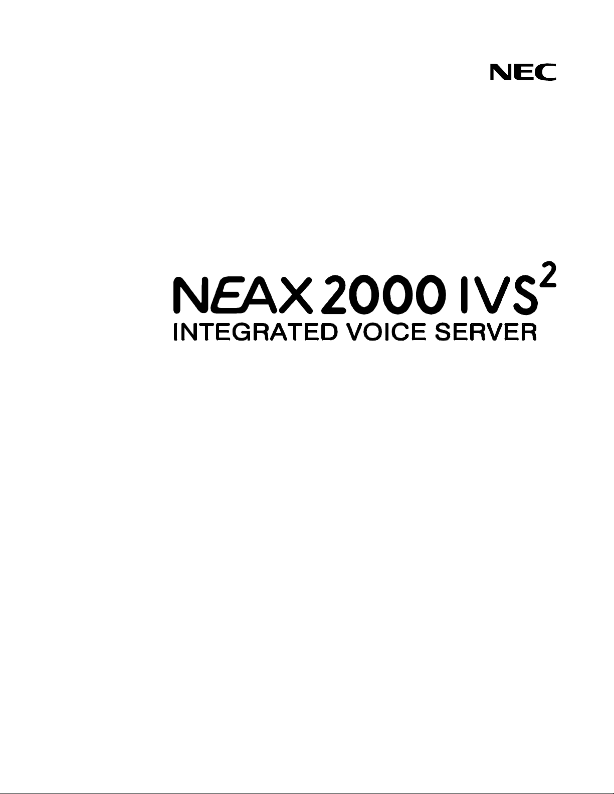
SYSTEM OUTLINE
The Wireless Communication System (WCS) interfaces withaPersonal Station (PS) via a Zone
Transceiver (ZT).
Three types of system configurations are available:
(1) Integrated Type
The system provides both PBX and WCS functions.
(2) Adjunct Type (Analog Interface)
The WCS is an adjunct system to the PBX linkedby LC-COT connection.
(3) Adjunct Type (CCIS Interface)
The WCS is an adjunct system to the PBX linkedby CCIS interface.
Figure 1-1 shows the system outline of the WCS.
Page 4
NEAX2000 IVS2WCS System Manual (PCS)
ND-70920 (E), Issue 1.0
Page 13
(1) Integrated Type
PS
CHAPTER 1 GENERAL INFORMATION
System Outline
Figure 1-1 WCS System Outline
PBX with WCS
PS
PS
ZT
SLT
D
term
CSI COT
LC
DLC
DAT
(2) Adjunct Type (Analog Interface)
PS
PS
ZT
PS
CSI COT
DAT CSH
WCS
LC
COT
CSH
NOTE
*
ANALOG
PBX
LC
LCSLT
(3) Adjunct Type (CCIS Interface)
PBX
PS
PS
PS
CSI DTI
ZT
DAT CSH
COT : Central Office Trunk
ZT : Zone Transceiver
CSH : CSI Handler
CSI : ZT Interface
WCS
CCIS
LC
*
COT
DAT : Digital Announcement Trunk
DLC : Digital Line Circuit
LC : Line Circuit
PS : Personal Station
*
DTI
NOTE
LCSLT
term
DLCD
: Virtual LC-COT Connection (NOTE)
NOTE: For the Integrated Type and Adjust Type (CCIS Interface), virtual LC-COT
Connection data assignment is required to each PS station.
NEAX2000 IVS2WCSSystemManual(PCS)
ND-70920 (E), Issue1.0
Page 5
Page 14

CHAPTER 1 GENERAL INFORMATION
Card Name and Function
CARD NAME AND FUNCTION
Table 1-1 shows the circuit card name and function for WCS.
Table 1-1 WCS Card Name and Function
CARD NAME
NAME
PZ-PW122 DC/DC PWR PowerSupply Card for Cell Station (Zone Transceiver)
Input: DC –24 V
Output: DC –48 V (1.7 A)
One card per PIM.
Max. 16 CS (ZT)s backed up by one card.
PN-AP00-A
[For North
DBM Data Base Module Card for WCS Roaming function
One card per WCS system.
America/Latin
America only]
PN-SC00 CCH Common Channel Handler Card
Transmits/receives signals on the common signalling
channel of No. 7 CCIS.
Used for WCS Adjunct Type (CCIS Interface).
PN-SC01 DCH D-channel Handler Card
Transmits/receives signals on the D-channel of ISDN
Primary Rate (23B + D) interface or WCS Roaming
interface.
FUNCTION OUTLINE
FUNCTIONAL
PN-SC03-A CSH CS (ZT) Handler Card
Provides the D-channel signaling interface and controls
max. four CSI cards, eight CS (ZT)s.
PN-2CSIA
[For North
America/
CSI 2-line Zone Transceiver InterfaceCard
Used to interface with the ZT, based on ISDN S-interface.
Max. two ZTs can be connected per CSI card.
Latin America]
Page 6
NEAX2000 IVS2WCS System Manual (PCS)
ND-70920 (E), Issue 1.0
Page 15

CHAPTER 1 GENERAL INFORMATION
Card Name and Function
Table 1-1 WCS Card Name and Function (Continued)
CARD NAME
FUNCTIONAL
NAME
FUNCTION OUTLINE
PN-2DATA DAT 2-line Digital Announcement Trunk Card
This card is usedfor Announcement Service on WCS.
Recording duration:Max. 60 seconds
PN-4DATC DAT 4-line Digital Announcement Trunk Card
This card is usedfor Announcement Service on WCS.
Recording duration: Max. 120 seconds
PN-24DTA-C DTI Digital Trunk Interface (23B + D, 1.5 Mbps) Card
Accommodates 24-channel PCM digital lines.
Used for WCS Adjunct (CCIS Interface) or for WCS
Roaming Interface.
PN-30DTC-A DTI Digital Trunk Interface (2 Mbps) Card
Accommodates 30-channel PCM digital lines.
Used for WCS Adjunct (CCIS Interface) or for WCS
Roaming Interface.
PZ-M537 EXPMEM Memory Expansion Card for MP Card
The following expansions are available when mounted on
PN-CP14 (MP) card:
Basic Memory expanded
Number of D
term
: 384 512
Number of PS : 128 256
Number of ISDN terminal : 64 128
Number of Speed Calling-Station
(Station Speed Dial) set :4000 10000
NEAX2000 IVS2WCSSystemManual(PCS)
ND-70920 (E), Issue1.0
Page 7
Page 16

CHAPTER 1 GENERAL INFORMATION
System Specifications
SYSTEM SPECIFICATIONS
Table 1-2 System Specifications
DESCRIPTION SPECIFICATIONS REMARKS
Wireless Protocol Based on second generation wireless
telephone system standard RCR-STD-28
FCC Sub part D, UTAM complied
Distancebetween
PBX and ZT
WIRE
DIAMETER
POWER SUPPLY WCS L O CAL WCS LOCAL WCS LOCAL
26 AWG 24 AWG 22 AWG
Interfacewith
aPBX
DISTANCE
1500 ft.
(457 m)
2000 ft.
(609 m)
2000 ft.
(609 m)
3000 ft.
(914 m)
3000 ft.
(914 m)
NOTE: At Nominal Voltage of –48 V.
Analog station line interface Adjunct Type
(Analog Interface)
T1 or E1 interface with CCIS Adjunct Type
(CCIS Interface)
3300 ft.
(1000 m)
Page 8
NEAX2000 IVS2WCS System Manual (PCS)
ND-70920 (E), Issue 1.0
Page 17

SYSTEM CAPACITY
Table 1-3 WCS System Capacity
CHAPTER 1 GENERAL INFORMATION
System Capacity
CAPACITY
Description
Integrated
Adjunct
(Analog)
PS NOTE 1 with PZ-M537 256
without PZ-M537 128
ZT 128
CSI 64
CSH 16
PS Simultaneous
Connections NOTE 1
with PZ-M537 216
without PZ-M537 128
Calling Area 32
ZT per Calling Area 128
NO TE 1: When using a PZ-M537 card, the capacity of PSs can be expanded to 256.
NO TE 2: Calling Area is a registered area to search first for a PS location.
The calling signal is sent to the ZTs that belong to the Calling Area.
Adjunct
(CCIS )
NEAX2000 IVS2WCSSystemManual(PCS)
ND-70920 (E), Issue1.0
Page 9
Page 18
CHAPTER 1 GENERAL INFORMATION
Time Slot Allocation
TIME SLOT ALLOCATION
CSH
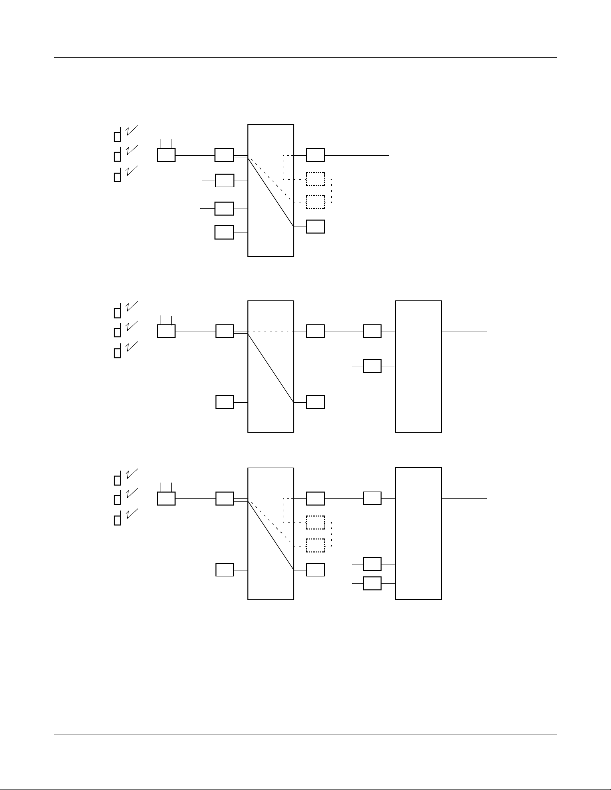
As shown in Figure 1-2, the CSH (PN-2CSIA) card uses the time slot on the basic memor y
Highway 4. Therefore, the total number of time slots for all CSH card must be 128 time slots or
less including all other application processor cards, which use the Highway 4.
Figure 1-2 Accommodation of CSH into TDSW
FOR L/TCARDS: MAX. 512 TIME SLOTS PER SYSTEM
FP0
FP1
FP2
FP3
TDSW (1024 TIME SLOTS)
DTI
CCH 1 TIME SLOT/CARD
CSH
HW4
HW6
AP00
DTI
PRT
MAX. 128 TIME SLOTS
MAX. 128 TIME SLOTS
MAX. 128 TIME SLOTS
MAX. 128 TIME SLOTS
30DTI: MAX. 32 TIME SLOTS/CARD
4TIMESLOTS/CARD
1 TIME SLOT/CARD
24 DTI: MAX. 24 TIME SLOTS/CARD
25 TIME SLOTS/CARD
BASIC HIGHWAY 4: Max. 128 TIME SLOTS PER SYSTEM
EXPANDED HIGHWAY 6: MAX. 128 TIME SLOTS PER SYSTEM
FOR AP CARDS: MAX.256 TIME SLOTS PER SYSTEM
CSI
The CSI (PN-2CSIA) card uses eight L/T time slots per card.
Page 10
NEAX2000 IVS2WCS System Manual (PCS)
ND-70920 (E), Issue 1.0
Page 19
CHAPTER 1 GENERAL INFORMATION
Outline of Multi-Site Roaming
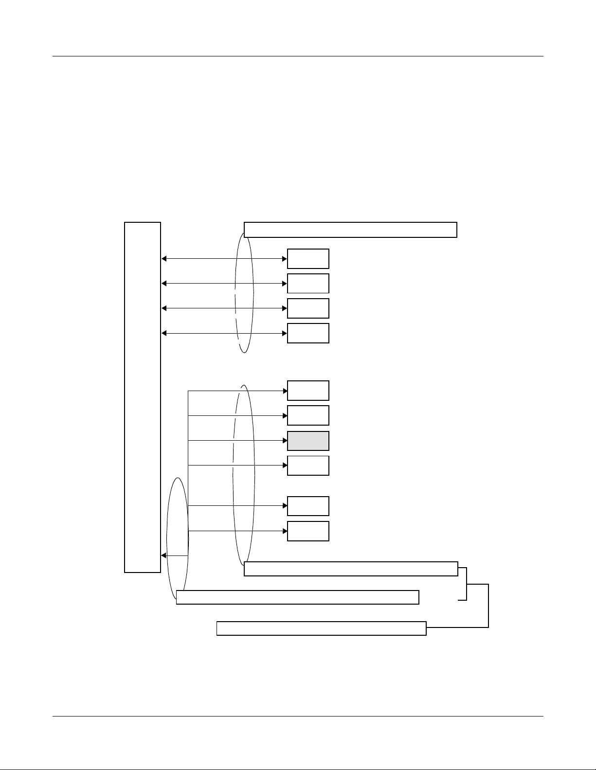
OUTLINE OF MULTI-SITE ROAMING
The PBX supports the JT-Q931a protocol and JT-11582 for signaling at Q-reference point
between PBXs on the private network. By supporting this protocol, the PSs can be used in any
Calling Area on the private network.
Figure 1-3 System Outline of Multi-Site Roaming
When a PS roams over the adjoining PBX’s Calling Area
PBX A PBX B
Dp Channel PrivateLine
(JT-Q931a)
ZT ZT
ROAMING
PS PS
When a PS roams over other Calling Area through the relaying office
PBX A PBX B
Dp Channel
Private Line
(JT-Q931a) (JT-Q931a)
ZT ZT
PS PS
PBX C
Dp Channel
Private Line
ZT
ROAMING
NEAX2000 IVS2WCSSystemManual(PCS)
ND-70920 (E), Issue1.0
NOTE: Alsoto the relaying office (PBX C), the installation and
the data assignment for Multi-Site Roaming are required.
Page 11
Page 20
CHAPTER 1 GENERAL INFORMATION
Outline of Multi-Site Roaming
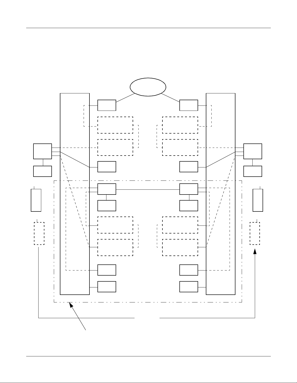
System Configuration
Figure 1-4 shows the system configuration for Multi-Site Roaming.
Figure 1-4 System Configuration of Multi-Site Roaming
PUBLIC
HOME PBX
NETWORK
VISITOR PBX
PS
PS
CSI
ZT
TRK
VIRTUAL
VIRTUAL
CSH
DTI
PLO
VIRTUAL
VIRTUAL
LC
TRK
LC
TRK
Dp Channel Private Line
(JT-Q931-a)
VIRTUAL
LC
VIRTUAL
TRK
VIRTUAL
LC
VIRTUAL
TRK
TRK
CSI
CSH
ZT
DTI
PS
PLO
PS
Page 12
DCH
DBM
Roaming
The equipment in this square is required for Multi-SiteRoaming.
DCH
DBM
NEAX2000 IVS2WCS System Manual (PCS)
ND-70920 (E), Issue 1.0
Page 21

CHAPTER 1 GENERAL INFORMATION
Outline of Multi-Site Roaming
Word Definition
Virtual LC: Virtual LC exists only on the system data, provided via non-hardware
supported LENs. The Virtual LC must be assigned by the system data
programming for operating Home PSs and Visitor PSs used for MultiSite Roaming, together with the Virtual TRK.
Virtual TRK: Virtual TRK (trunk) exists only on the system data, provided via non-
hardware supported LENs. The Virtual TRK must be assigned by the
systemdataprogrammingforoperating Home PSs andVisitorPSsused
for Multi-Site Roaming, together with the Virtual LC.
Individual PS number: Individual PS number i s assigned to a PS to identify the PS on the
Roaming network. It must be an unique number in the network.
Network ID method: Network ID method is one method to operate Multi-Site Roaming. A
Roaming PS must have two SYS-ID on the Network ID method. One is
main SYS-ID for Home PBX, and another is Network ID for Roaming
network. The Network ID is used to define whether the PS can operate
under the control of PBXs on the Roaming network. The Network ID
must be the same for all PBXs within the same network.
Visitor PBX: When a PS leaves control of a PBXto which it belongs originally, and is
operating in a zone of another PBX, the PBX is called Visitor PBX.
Visitor PS: When a PS leaves control of a PBX to which it belongs o riginally, and is
operating in a zone of another PBX, the PS is called Visitor PS.
Home PBX: Home PBX is a PBX to which a PS ordinarily belongs.
Home PBX ID: Home PBX ID is a unique number to identify the PBX on the Roaming
network.
Home PS: When a PS operates under control of a PBX to which the PS originally
belongs, the PS is called Home PS.
Roaming number: Roaming number is assigned to a Visitor PS temporarily, when the PS
is roaming to a Visitor PBX. The actual Roaming number is Virtual LC
station number assigned as a pilot station of Station Hunting group on
the Visitor PBX.
NEAX2000 IVS2WCSSystemManual(PCS)
ND-70920 (E), Issue1.0
Page 13
Page 22

CHAPTER 1 GENERAL INFORMATION
Outline of Multi-Site Roaming
HLR: Home Location Register. A database to store the location r egistration
data of the Home PS.
VLR: Visitor Location Register. A database to store the location registration
data of the Visitor PS temporaril y, when the Visitor PS is in the zone of
another PBX.
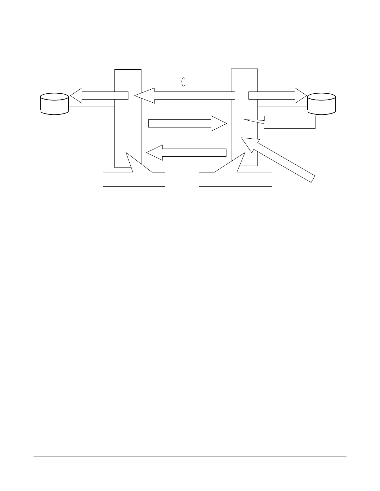
System Operation Summary
• PS Location Registration
(1) In the zone of the Visitor PBX, the Visitor PS requests the Visitor PBX for location
registrationof its own.
(2) The Visitor PBX analyzes the number sent from the Visitor PS and detects the Home
PBX of Visitor PS.
(3) The Visitor PBX inquires of the Home PBX about the profiles; various data which is
assigned to the PS for the operation as a Visitor PS.
(4) The Home PBX analyzesthenumberincludedwiththe inquiry and detects whether the
Visitor PS is one of the Home PS of its own.
If the Visitor PS is detected as a PS which belongs to another PBX, the PBX forwards
the inquiry to the corresponding route.
(5) If the V isitor PS is detected as a Home PS,theHome PBX sends the Visitor PS profiles
to the Visitor PBX.
(6) The Visitor PBX confirms the profiles sent from the Home PBX, and determines the
Roaming number for the Visitor PS.
The actual Roamingnumberis Virtual LC station number assigned as a pilot station of
Station Hunting Group on the Visitor PBX.
(7) The Visitor PBX registers the profile data of the Visitor PS to the VLR.
(8) Then notifies the completion of registration to the Home PBX. The notification contains
the Roaming number determined.
(9) The Home PBX receives the notification and stores the Roaming number to the HLR.
Page 14
NEAX2000 IVS2WCS System Manual (PCS)
ND-70920 (E), Issue 1.0
Page 23
CHAPTER 1 GENERAL INFORMATION
Figure 1-5 Location Registration
Outline of Multi-Site Roaming
HLR
HOME PBX
(9) Registration to HLR (8)
(4) Analyze the inquiry
VISITOR PBX
Q931a Digital Line
Notificationcompletion of registration
(5) Sending profiles
(3) Profiles inquiry
(2) Interpreting Home PBX
(7) Registration to VLR
(6) Confirming profiles
(
1
)
R
e
q
u
e
s
t
i
n
g
l
o
c
a
t
i
VLR
o
n
r
e
g
i
s
t
r
a
t
i
o
n
VISITOR
PS
NEAX2000 IVS2WCSSystemManual(PCS)
ND-70920 (E), Issue1.0
Page 15
Page 24
CHAPTER 1 GENERAL INFORMATION
Outline of Multi-Site Roaming
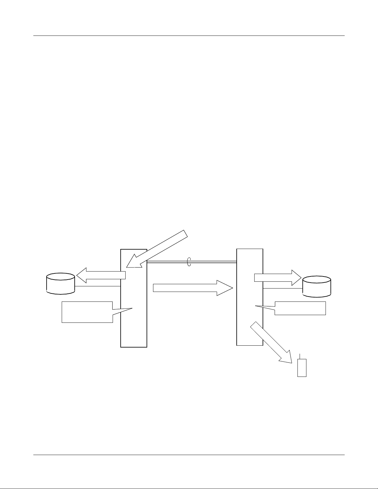
• Call Termination to Visitor PS
(1) The Home PBX receives the call from another PBX and sends to a Home PS.
(2) The Home PBX refers the HLR informationof the PS.
(3) From the Roaming number contained in the HLR information, the Home PBX detects
whether the Home PS is roaming.
(4) The Home PBX inquires of the Visitor PBX about the call t ermination to the Visitor PS.
The inquiry c ontains the roaming data of the Visitor PS, such as Roaming number and
Individual PS number.
(5) he Visitor PBX analyzes the Roaming number and refers to the VLR information of the
Visitor PS in accordance with the Individual PS number.
(6) The Visitor PBX confirms the VLR information.
(7) The Visitor PBX terminates the call to the Visitor PS.
(2) Referring HLR
HLR
(3) Interpreting the
location of the PS
Figure 1-6 CallTermination
X
B
P
r
e
h
t
HOME PBX
C
)
1
(
a
o
n
a
m
o
r
f
l
l
Q931a Digital Line
(4) Call termination inquiry
VISITOR PBX
(5) Referring VLR
VLR
(6) Confirming VLR
(7) Call Termination
VISITOR
PS
Page 16
NEAX2000 IVS2WCS System Manual (PCS)
ND-70920 (E), Issue 1.0
Page 25

CHAPTER 1 GENERAL INFORMATION
Outline of Multi-Site Roaming
Service Conditions
(1) Trunk
• Multi-Site Roaming can be executed only on trunk connection between PBXs based on JTQ931a protocol.
• To each trunk route of JT-Q931a trunks, it can be specified whether Multi-Site Roaming is
provided or not.
• The JT-Q931a trunks can be used by single line telephone stations and D
originating or receiving calls in the same manner as common trunks.
(2) Data Base M odule
• The Data Base Module (DBM) card (PN-AP00-A) is required per PBX.
• The DBM card cannot be used as billing application processor (for SMDR, MCI, PMS, or
Hotel printer).
• Systemdatastored in the memory of theDBMcardcanbesaved,loaded,and verified from
a MAT. (Memory Area No.:A, Memory Address: 00900-10870, File Extension: DMA)
• A Roaming network consists of maximum 512 PBXs.
• Visitor Location Register (VLR) information for maximum 512 Visitor PSs can be recorded
to a system.
VLR informationisthe variousinformation of Visitor PS and is made in the memory of DBM
on the Visitor PBX when the PS is roaming.
When theVLRinformation exceedsfor morethan 512PSs,DBMoverwritestheoldestVLR
information.
term
stationsfor
(3) Home PS/Visitor PS
To use the PSs for Multi-Site Roaming, the following items must be assigned to the PSs:
- SYS-ID; SYS-ID of Home PBX.
- PS-ID; A unique number for identifying the PS.
- Individual PS number; The same number with the Home PBX ID.
- Extension number; The same number with the Individual PS number.
- Network ID; It must be assigned when the Roaming network adopts Network ID methods.
- Home PBX ID; A unique number for identifying the PBX on the Roaming network.
NEAX2000 IVS2WCSSystemManual(PCS)
ND-70920 (E), Issue1.0
Page 17
Page 26

This page is for your notes.
Page 18
NEAX2000 IVS2WCS System Manual (PCS)
ND-70920 (E), Issue 1.0
Page 27

CHAPTER 2
INSTALLATION
This chapter explains the hardware installation procedure to provide
WCS interface to the PBX.
NEAX2000 IVS2WCSSystemManual(PCS)
ND-70920 (E), Issue1.0
Page 19
Page 28
CHAPTER 2 INSTALLATION
Precautions
PRECAUTIONS
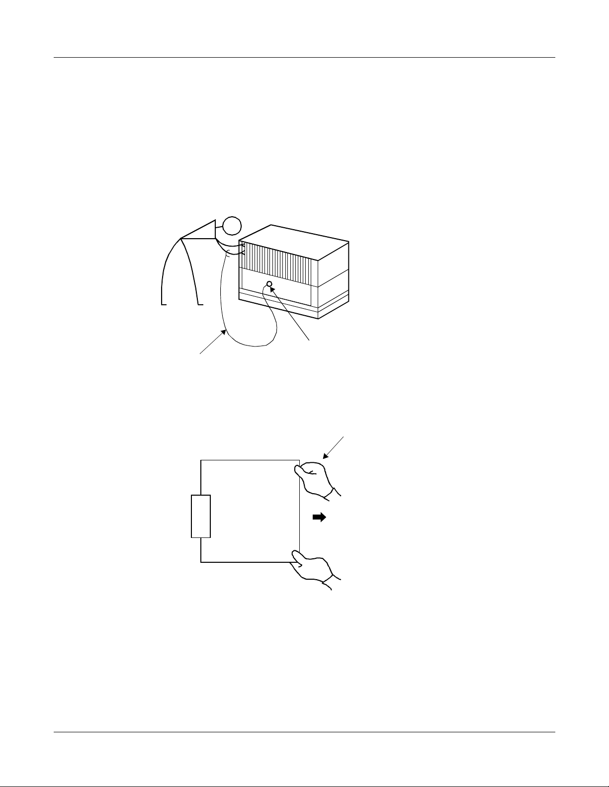
Static Electricity Guard
You must wear a grounded wrist strap to protect circuit cards from static electricity.
Figure 2-1 Static Electricity Guard (1 of 2)
WHEN PLUGGING/UNPLUGGING A CIRCUIT CARD
•
PBX
•WHEN
FRAME GROUND SCREW
WRIST STRAP
HOLDING A CIRCUIT CARD
NEVER TOUCH THE COMPONENTS OR
SOLDERED SURFACE WITH BARE HANDS.
CARD FRONT
Page 20
NEAX2000 IVS2WCS System Manual (PCS)
ND-70920 (E), Issue 1.0
Page 29
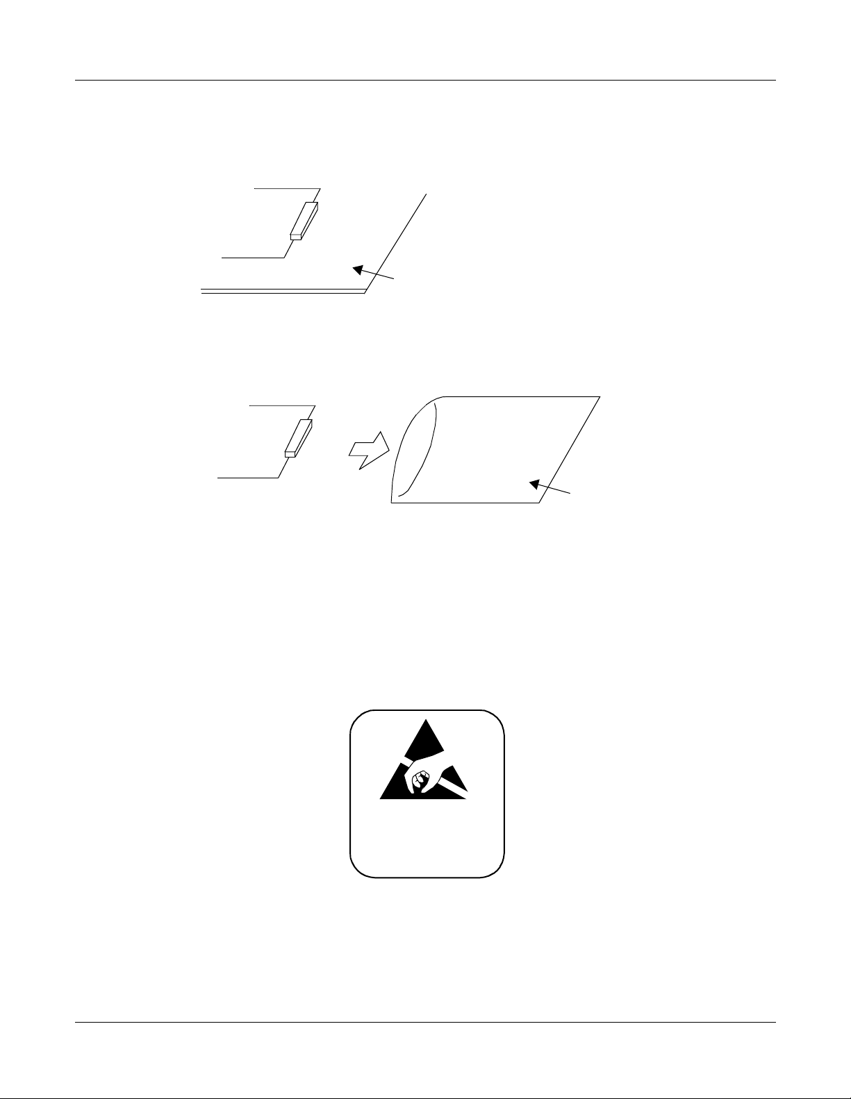
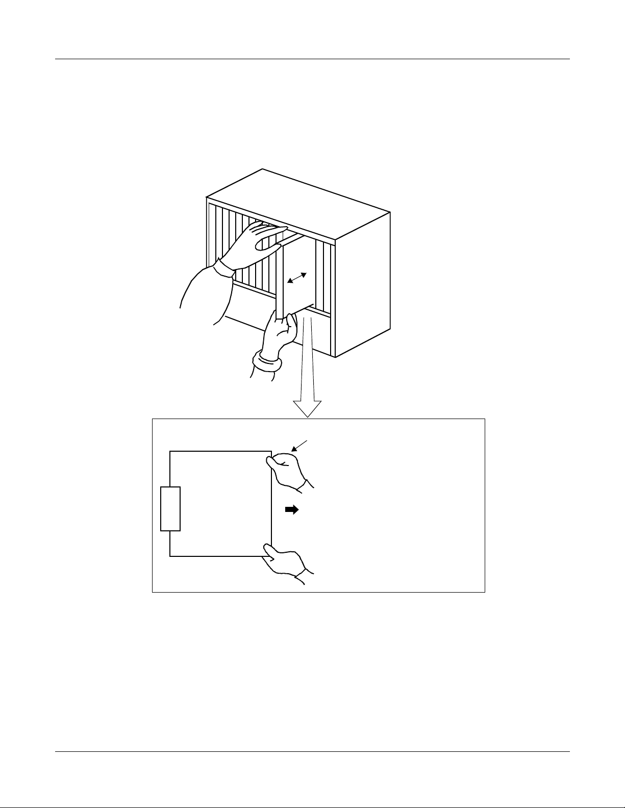
Figure 2-1 Static Electricity Guard (2 of 2)
• WHEN MAKING A SWITCH SETTING ON A CIRCUIT CARD
CIRCUIT
CARD
WEAR A WRI ST STRAP AND PERFORM
THE WORK ON A GROUNDED
CONDUCTIVE WORK SURFACE.
• WHEN CARRYING A CIRCUIT CARD
CHAPTER 2 INSTALLATION
Precautions
CIRCUIT
CARD
CONDUCTIVE
POLYET HYLE NE
BAG
WHEN CARRYING A CIRCUIT
CARD AROUND, KEEP THE
CARD IN A CONDUCTIVE
POLYET HYLE NE BAG.
The mark shown below is attached to the sheet for the work in which circuit cards are handled.
When engaging in such work, the installer must be careful not to cause damage by static
electricity.
ATTENTION
Contents
Static Sensitive
Handling
Precautions Required
NEAX2000 IVS2WCSSystemManual(PCS)
ND-70920 (E), Issue1.0
Page 21
Page 30
CHAPTER 2 INSTALLATION
Precautions
CAUTION
You must hold the edge of a circuit card when plugging or unplugging the circuit card. If you
touch another area, you may be exposed to hazardous voltages.
PBX
NEVER TOUCH THE COMPONENTS OR
SOLDEREDSURFACE WITH BARE HANDS.
CARD FRONT
Page 22
NEAX2000 IVS2WCS System Manual (PCS)
ND-70920 (E), Issue 1.0
Page 31

CHAPTER 2 INSTALLATION
Precautions
Turning Power ON
Caution
1. When the operating power is being supplied to the PZ-PW121 card, do not plug/unplug
this circuit card into/from its mounting slot.
2. When the system is configured with two or more PIMs, the BUS cable is providing gang
control for the PZ-PW121 card of PIM0 and other PIMs. Therefore, if the power of PIM0 is
off, no power is supplied to the whole system even when the power switch(s) of other
PIMs are left on. Note, however, that the battery continues to charge even under these
circumstances.
3. Do not turn off the PZ-PW121 card on PIM1 to PIM7 when the system is operating.
(1) Check the switch position of each PZ-PW121 card before turning power on.
• Make sure that the AC120V/240V selector switchis positioned to appropriate voltage for
each country (AC120V or AC240V).
SW
240 V100 V/120 V
• Make sure that the battery mode selector switch is positioned as shownbelowto meet the
kind of battery:
SW101
OFF
12
1:Notused
2 : ON (SEAL/FLOAT2)
OFF (OPEN/FLOAT1)
ON
(2) Turn the SW1 switches of all the PZ-PW121 cards to ON. First, turn ON PIM1 to PIM7.
Then, turn ON PIM0 l ast of all.
NEAX2000 IVS2WCSSystemManual(PCS)
ND-70920 (E), Issue1.0
Page 23
Page 32

CHAPTER 2 INSTALLATION
Precautions
Turning Power OFF
(1) Before turning power off ensure that all circuits are not in use.
(2) Turn the SW1 switches of all the PZ-PW121cards to OFF. First, turn OFF PIM0. Then, turn
OFF PIM1 to PIM7.
Page 24
NEAX2000 IVS2WCS System Manual (PCS)
ND-70920 (E), Issue 1.0
Page 33

CHAPTER 2 INSTALLATION
Required Equipment
REQUIRED EQUIPMENT
Table 2-1 shows the equipment required to provide the WCS interface to the system.
Table 2-1 WCS Required Equipment
EQUIPMENT DESCRIPTION QUANTITY REMARKS
PZ-PW122
(DC/DC PWR)
–48V Power supply card for ZT 1-8 One per PIM
16 ZT powered
/card
PWR CNT CA-D Power Control Cable-D (between
1-7 ForPIM1-7
PW121/PW122 and BWB)
PWR CNT CA-E Power Control Cable-E (between
1ForPIM0
PW121/PW122 and BWB)
PN-2CSIA (CSI) ZT Interface card 1-64 2 ZT/card
PN-SC03-A (CSH) ZT Handler card 1-16 4 CSI/card
PN-2DATA (DAT) Digital Announcement Trunk N N: As required for
Announcement
PN-4DATC (DAT)
PZ-M537
(EXPMEM)
Memory Expansion card 1 For more than 128
Service
PS
PN-4COT Central Office Trunk N For Adjunct Type
PN-8COT Central Office Trunk N
(Analog Interface)
4COT: 4PS/card
8COT: 8PS/card
PN-24DTA-C (DTI) 24-channel DTI card 1-8 For Adjunct Type
PN-30DTC-A
30-channel DTI card 1-4
(CCIS Interface)
(DTI)
PN-SC00 (CCH) Common Channel Handler card 1-8
NEAX2000 IVS2WCSSystemManual(PCS)
ND-70920 (E), Issue1.0
Page 25
Page 34

CHAPTER 2 INSTALLATION
Required Equipment
Table 2-1 WCS Required Equipment (Continued)
EQUIPMENT DESCRIPTION QUANTITY REMARKS
PN-24DTA-C
24-channel DTI card 1-8 For Roaming
(24DTI)
PN-30DTC-A
30-channel DTI card 1-4
(30DTI)
PN-SC01 (DCH) D-channel Handler card 1-8
PN-AP00-A (DBM) Roaming Data Base Module card 1
Page 26
NEAX2000 IVS2WCS System Manual (PCS)
ND-70920 (E), Issue 1.0
Page 35

CHAPTER 2 INSTALLATION
Installation Procedure
INSTALLATION PROCEDURE
Installthe equipmentforWCSaccordingto the procedure shownin Figure 2-2. Figure2-3 shows
the procedure for Multi-Site Roaming.
Figure 2-2 Installation Procedure
START
No
MOUNTING PW122 CARD
More than 128 PS required?
Yes
MOUNTING EXPMEM CARD
MOUNTING CSH CARD
MOUNTING CSI CARD
CONNECTION OF ZT
Page 29
Page 31
Page 32
Page 33
Page 34
NEAX2000 IVS2WCSSystemManual(PCS)
ND-70920 (E), Issue1.0
END
Page 27
Page 36

CHAPTER 2 INSTALLATION
Installation Procedure
Figure 2-3 Installation Procedure for Multi-Site Roaming
START
MOUNTING DTI, DCH
AND DBM CARD
SELECTION OF PLO IN
MP CARD
CABLE CONNECTI ON
VIA MDF
END
Page 37
Page 37
Page 28
NEAX2000 IVS2WCS System Manual (PCS)
ND-70920 (E), Issue 1.0
Page 37

MOUNTING PW122 CARD
CHAPTER 2 INSTALLATION
Mounting PW122 Card
Mount the PW122 card into the PIM as shown in Figure 2-4.
(1) Attach four screws preliminar y to the PZ-PW122 card.
ATTENTION
Contents
Static Sensitive
Handling
Precautions Required
(2) MountthePZ-PW122card into the PIMwhichaccommodates the CSIcards,and fastenthe
screws.
NO TE: Screws are attached to the PZ-PW122 card.
Figure 2-4 Mounting PZ-PW122 into PIM
PZ-PW122
PIM
NEAX2000 IVS2WCSSystemManual(PCS)
ND-70920 (E), Issue1.0
Page 29
Page 38

CHAPTER 2 INSTALLATION
Mounting PW122 Card
(3) Connect the PWR CNT CA-E or PWR CNT CA-D, and POWER OUTPUT
CABLE (–48 V, E ) to the PZ-PW122 card as shown in Figure 2-5.
Figure 2-5 Cable Connection between PZ-PW121/PZ-PW122 and BWB
PIM
PZ-PW121 BWB (BACK WIRING BOARD)
ATTENTION
Contents
Static Sensitive
Handling
Precautions Required
PWR1
CN103
PWR0C
PZ-PW122
POWER OUTPUT CABLE (+90 V, CR, E)
PWR CNT CA-E (FOR PIM0)
PWR CNT CA-D (FOR PIM1TO PIM7)
PWR0A
PWR0B
CARD SLOT AREA
LTC CONNECTOR AREA
POWER OUTPUT CABLE (+5 V, -27 V, E)
POWER OUTPUT CABLE (-48 V, E)
Page 30
NEAX2000 IVS2WCS System Manual (PCS)
ND-70920 (E), Issue 1.0
Page 39

MOUNTING EXPMEM CARD
CHAPTER 2 INSTALLATION
Mounting EXPMEM Card
The EXPMEM (PZ-M537) card is required when the number of PS is more than
128.
(1) Confirm the correct switch settings. See CHAPTER 4
(2) Mount the EXPMEM card on the MP card.
For details, refer to the Installation Procedure Manual.
(3) Then, mount the MP card into the MP slot of PIM0.
ATTENTION
Contents
Static Sensitive
Handling
Precautions Required
NEAX2000 IVS2WCSSystemManual(PCS)
ND-70920 (E), Issue1.0
Page 31
Page 40

CHAPTER 2 INSTALLATION
Mounting CSH Card
MOUNTING CSH CARD
(1) Before mounting the CS H (PN-SC03-A) card, set the MB switch to UP
position, and set the otherswitches to appropriate position.
ATTENTION
Contents
Static Sensitive
Handling
Precautions Required
See CHAPTER 4.
(2) Mount the CSH card in the AP slots of PIM0 through PIM7.
PIM0-7: AP00-AP11 slots
The AP11 slot on PIM0 is available only when the FP card is not mounted on the FP11 slot
on P IM0.
(3) After mounting the card, set the MB switch to DOWN position to put the card in service.
Page 32
NEAX2000 IVS2WCS System Manual (PCS)
ND-70920 (E), Issue 1.0
Page 41

MOUNTING CSI CARD
CHAPTER 2 INSTALLATION
Mounting CSI Card
(1) Beforemounting theCSI(PN-2CSIA) card,confirmthe correct switchsettings.
See CHAPTER 4.
(2) Mount the CSI card in the LT slots of PIM0 though PIM7.
PIM0-7: LT00-L T07 slots
ATTENTION
Contents
Static Sensitive
Handling
Precautions Required
NEAX2000 IVS2WCSSystemManual(PCS)
ND-70920 (E), Issue1.0
Page 33
Page 42

CHAPTER 2 INSTALLATION
Connection of ZT
CONNECTION OF ZT
Connect the cable to a ZT via the MDF as desc ribed in this section.
• Location ofLT slots andLTC connectors for ZT ( Figure 2-1)
• MDF Cross connection for ZT (Figure 2-2)
Figure 2-1 Location of LT Slotsand LTC Connectors for ZT
L
L
L
L
L
L
L
L
L
L
L
L
T
T
T
T
T
T
T
T
T
T
T
T
0
0
0
0
0
0
0
0
0
0
1
1
0
1
2
3
4
5
6
7
8
9
0
1
01
02
03
04
05
06
07
08
09
10
11
12
13
14
15
16
17
18
19
20
21
22
23
24
25
RA0
TA0
RA1
TA1
RA0
TA0
RA1
TA1
RA0
TA0
RA1
TA1
MJ
LTC0
26
27
28
29
30
31
32
33
34
35
36
37
38
39
40
41
42
43
44
45
46
47
48
49
50
RB0
TB0
RB1
TB1
RB0
TB0
RB1
TB1
RB0
TB0
RB1
TB1
MN
LT00
SLOT
LT01
SLOT
LT02
SLOT
01
02
03
04
05
06
07
08
09
10
11
12
13
14
15
16
17
18
19
20
21
22
23
24
25
RA0
TA0
RA1
TA1
RA0
TA0
RA1
TA1
RA0
TA0
RA1
TA1
LTC1
26
27
28
29
30
31
32
33
34
35
36
37
38
39
40
41
42
43
44
45
46
47
48
49
50
RB0
TB0
RB1
TB1
RB0
TB0
RB1
TB1
RB0
TB0
RB1
TB1
LT03
SLOT
LT04
SLOT
LT05
SLOT
01
02
03
04
05
06
07
08
09
10
11
12
13
14
15
16
17
18
19
20
21
22
23
24
25
RA0
TA0
RA1
TA1
RA0
TA0
RA1
TA1
LTC2
26
27
28
29
30
31
32
33
34
35
36
37
38
39
40
41
42
43
44
45
46
47
48
49
50
RB0
TB0
RB1
TB1
RB0
TB0
RB1
TB1
LT06
SLOT
LT07
SLOT
LT08
SLOT
01
02
03
04
05
06
07
08
09
10
11
12
13
14
15
16
17
18
19
20
21
22
23
24
25
LTC3
26
27
28
29
30
31
32
33
34
35
36
37
38
39
40
41
42
43
44
45
46
47
48
49
50
LT09
SLOT
LT10
SLOT
LT11
SLOT
Page 34
NEAX2000 IVS2WCS System Manual (PCS)
ND-70920 (E), Issue 1.0
Page 43

BWB
CHAPTER 2 INSTALLATION
Connection of ZT
Figure 2-2 MDF Cross Connection for ZT
PBX
(PIM0-7)
CSI
TWISTED-PAIR
CABLE
LTC0/LTC1/LTC2 CONNECTOR
1RA0 26RB0
ZT No. 0
ZT No. 1
ZT No. 2
ZT No. 3
2TA0 27TB0
3RA1 28RB1
4TA1 29TB1
5RA2 30RB2
6TA2 31TB2
7RA3 32RB3
8TA3 33TB3
934
10 35
11 36
12 37
13 38
14 39
15 40
16 41
17 42
18 43
19 44
20 45
21 46
22 47
23 48
24 49
25 50
LTC CONNECTOR
CAUTION: Incorrect wiring may causesevere damage to the equipment.
NEAX2000 IVS2WCSSystemManual(PCS)
ND-70920 (E), Issue1.0
MDF
Modular
Connector
MDF
TA
RA
RB
TB
TB
RB
ZT
TA
RA
Modular plug
NO TE: Confirm that all feed polarity TA/TB
and RA/RB is normal before connecting ZT to RJ-45 Modular jack.
TA/TB minus
RA/RB plus
To Z T
Modular Jack
(RJ-45)
Page 35
Page 44

CHAPTER 2 INSTALLATION
Connection of ZT
Figure 2-3 MDF Cross Connection via MDF for ZT
Modular
Connector
(8)
(1)
8
FUNCTION POLAR ITY
TERMINAL
NUMBER
COLOR
TERMINAL
NUMBER
TERMINAL
EQUIPMENT
CSI SIGNAL FEED
1 blue a Not used Not used
2 orange b Not used Not used
3 black c Transmission Reception + – RA
4 red d Reception Transmission + – TA
5 green e Reception Transmission – + TB
6 yellow f Transmission Reception – + RB
7 brown g Not used Not used
8 slate h Not used Not used
NO TE: RJ-45 Modular Jack is highly recommended.
4
5
6
7
TERMINAL
1
2
3
CSI
Page 36
Keep all wiring straight t o the jack and perform all reverses at the cross connect for
future changes.
NEAX2000 IVS2WCS System Manual (PCS)
ND-70920 (E), Issue 1.0
Page 45

CHAPTER 2 INSTALLATION
Installation for Multi-Site Roaming
INSTALLATION FOR MULTI-SITE ROAMING
(1) Before mounting the DTI (PN-24DTA/PN-30DTC), DCH (PN-SC01), DBM (PN-AP00-A)
card, set the MB switch to UP position, and set the other switches to appropriate position.
See CHAPTER 4.
(2) Mount the DTI, DCH, DBM card in AP slots of PIM0 though PIM7.
PIM0-7: AP00-AP11 slots
(3) After mounting the card, set the MB switch to DOWN position to put the card in service.
(4) To select PLO in the MP card, set the switches of the M P card. See CHAPTER 4.
(5) Connect the cable to a CSU via the MDF for DTI as shown in Figure 2-4.
• Location of AP Slots and LTC Connectors for DTI (Figure 2-5)
• Example of MDF Cross Connection for DTI ( Figure 2-6)
Figure 2-4 DTI Cable Connection via MDF
PBX
BWB
NO TE: The CSU must be installed to interface with the network, and must be installed on
(PIM0-PIM7)
DTI
TWISTED-PAIR
CABLE
LTC0/LTC1/LTC2/LTC3
CONNECTOR
MAX. 200 m (655 ft.).... 24DTI
MAX. 400 m (1310 ft.).. 30DTI
the premises where the PBX is.
MDF
CSU
NEAX2000 IVS2WCSSystemManual(PCS)
ND-70920 (E), Issue1.0
Page 37
Page 46

CHAPTER 2 INSTALLATION
Installation for Multi-Site Roaming
Figure 2-5 Location of AP Slots and LTC Connectors for DTI
L
L
L
L
L
L
L
L
L
L
L
L
T
T
T
T
T
T
T
T
T
T
T
T
1
1
0
0
0
0
0
0
0
0
0
0
1
0
9
8
7
6
5
4
3
2
1
0
/
/
/
/
/
/
/
/
/
/
/
/
A
A
A
A
A
A
A
A
A
A
A
A
P
P
P
P
P
P
P
P
P
P
P
P
1
1
0
0
0
0
0
0
0
0
0
0
1
0
9
8
7
6
5
4
3
2
1
0
01
02
03
04
05
06
07
08
09
10
11
12
13
14
15
16
17
18
19
20
21
22
23
24
25
RA
TA
RA
TA
RA
TA
MJ
LTC0
26
27
28
29
30
31
32
33
34
35
36
37
38
39
40
41
42
43
44
45
46
47
48
49
50
RB
TB
RB
TB
RB
TB
MN
AP00
SLOT
AP01
SLOT
AP02
SLOT
01
02
03
04
05
06
07
08
09
10
11
12
13
14
15
16
17
18
19
20
21
22
23
24
25
RA
TA
RA
TA
RA
TA
LTC1
26
27
28
29
30
31
32
33
34
35
36
37
38
39
40
41
42
43
44
45
46
47
48
49
50
RB
TB
RB
TB
RB
TB
AP03
SLOT
AP04
SLOT
AP05
SLOT
01
02
03
04
05
06
07
08
09
10
11
12
13
14
15
16
17
18
19
20
21
22
23
24
25
RA
TA
RA
TA
RA
TA
LTC2
26
27
28
29
30
31
32
33
34
35
36
37
38
39
40
41
42
43
44
45
46
47
48
49
50
RB
TB
RB
TB
RB
TB
AP06
SLOT
AP07
SLOT
AP08
SLOT
01
02
03
04
05
06
07
08
09
10
11
12
13
14
15
16
17
18
19
20
21
22
23
24
25
RA
TA
RA
TA
RA
TA
LTC3
26
27
28
29
30
31
32
33
34
35
36
37
38
39
40
41
42
43
44
45
46
47
48
49
50
RB
TB
RB
TB
RB
TB
AP09
SLOT
AP10
SLOT
AP11
SLOT
Page 38
NEAX2000 IVS2WCS System Manual (PCS)
ND-70920 (E), Issue 1.0
Page 47

CHAPTER 2 INSTALLATION
Installation for Multi-Site Roaming
Figure 2-6 Example of MDF Cross Connection for DTI
AP05
PIM 0
RA
RB
TA
TB
LTC1 (J)
17
18
43
42
LTC1
JP MDFPN-24DTA/PN-30DTC
RECEIVE
17
42
18
43
LTC1 (P)
RA
RB
TA
TB
TRANSFER
TO CSU
17
18
19
20
RATA42
43
44
45
RB
TB
42
43
44
45
RBTB17
18
19
20
RA
TA
NEAX2000 IVS2WCSSystemManual(PCS)
ND-70920 (E), Issue1.0
Page 39
Page 48

This page is for your notes.
Page 40
NEAX2000 IVS2WCS System Manual (PCS)
ND-70920 (E), Issue 1.0
Page 49

CHAPTER 3
SYSTEM DATA
PROGRAMMING
Thischapterexplainsthep rogrammingprocedureto provide the WCS
feature to the PBX.
NEAX2000 IVS2WCSSystemManual(PCS)
ND-70920 (E), Issue1.0
Page 41
Page 50

CHAPTER 3 SYSTEM DATA PROGRAMMING
How to Read This Chapter
HOW TO READ THIS CHAPTER
In the programming procedure, the meaning of (1), (2), and markings are as follows.
(1) : 1st Data
(2) : 2nd Data
: Initial Data
With the system data clear command (CM00, CM01), the data with this marking is automatically
assigned for each command.
INITIAL
: A reset of the MP card is required after data setting.
Press SW1 switch on the MP card.
DBM INITIAL
: A reset of the DBM card is required after data setting.
Set the Make Busy switch to UP and then DOWN.
For general description, operating procedure, service conditions of WCS features, refer to the
WCS Features and Specifications.
Page 42
NEAX2000 IVS2WCS System Manual (PCS)
ND-70920 (E), Issue 1.0
Page 51

CHAPTER 3 SYSTEM DATA PROGRAMMING
Progamming Summary
PROGAMMING SUMMARY
Perform the system data programming related to the WCS according to the following procedure.
For other system data related to the PBX, refer to the Command Manual and the CCIS System
Manual.
Initial Setup of System
START
VIRTUAL LINE/TRUNK DATA
PROGRAMMING
ZT DATA PROGRAMMING
ZT AUTHORIZATION
PS DATA PROGRAMMING
TYPE OF SYSTEM?
Adjunct System
(Analog Interface)
TRUNK DATA
PROGRAMMING
WCS FEATURE PROGRAMMING
Page 46
By NTAC or LVP
Page 53
Adjunct System (CCIS Interface)Integrated System
CCIS DATA PROGRAMMING
NOTE
VIRTUAL LINE/TRUNK DA TA
PROGRAMMING
Page56Page 59Page 56
Page 64
NEAX2000 IVS2WCSSystemManual(PCS)
ND-70920 (E), Issue1.0
MULTI-SITE ROAMING
DATA PROGRAMMING
MAINTENANCE DATA
PROGRAMMING
END
Page 80
Page 101
NOTE: Refer to the CCIS System
Manual.
Page 43
Page 52

CHAPTER 3 SYSTEM DATA PROGRAMMING
Progamming Summary
Changing ZT Data in Service
When you change the ZT data (CM10, CM06, CMAD, CMAE) in service, make busy of the ZT is
required. In this case, do the following procedure.
START
NOYES
CHANGE OF ZT DATA?
MAKE BUSY OF ZT
(CME5 Y=3>2)*
CHANGE OF ZT DATA
(CM10,CM06,CMAD, CMAE)
MAKE IDLE OF ZT
(CME5 Y=3>1)
NOTE
CHANGE OF ZT NUMBER
(CM10)
CALL NTAC
ACCESS TO LVP SERVER
or
INPUT THE REQUIRED DATA
FROM PC
BY MATWorX
CHANGE OF OTHER DATA
END
NO TE: To make busy or make idle the ZT in service, assign data as follows:
CME5Y=3
(1) 000-127: ZT No.
(2) 1: Make idle
2: Make busy after calls finished.
NEAX2000 IVS2WCS System Manual (PCS)
Page 44
ND-70920 (E), Issue 1.0
Page 53

CHAPTER 3 SYSTEM DATA PROGRAMMING
Progamming Summary
Changing PS Data
If you change the PS data which has been already downloaded to a PS, do PS data download
again by CM1D.
CM1D YY=20
(1) X-XXXXXXXX: PS station No.
(2) 1
Replacing PS
When replacingthe PS with a new one, moreovera ssigning the same PS number to the new PS,
delete the PS number registered to the WCS by CM1C is required before downloading the new
PS data.
CM1C
(1) 000-255: Virtual PS LEN
(2) CCC: Clear
NEAX2000 IVS2WCSSystemManual(PCS)
ND-70920 (E), Issue1.0
Page 45
Page 54

CHAPTER 3 SYSTEM DATA PROGRA MMING
ZT Data Programming
ZT DATA PROGRAMMING
Initial Setup
START
CM05
CM10
CM06
DESCRIPTION DATA
Assign an AP number to the CSH card.
The AP number must match the SENSE
switch settings on the CSH card.
INITIAL
Assign a ZT number to the required LEN.
NOTE: The ZT number mustbe
assigned to the first LEN (Level
0) and/or second LEN (Level 2)
of each LT slot.
Assign a data path between the CSH and
the CSI. D channel Block number is used
to assign the control data path between
the CSH and CSI.
One CSH had 4 D channel Blocks, and 1
D Channel Block controls 1 CSI.
NOTE: The firstLEN (Level0) mustbe
assigned as the 2nd data.
•
Y=0
(1)
04-15, 20-31: AP No.
(2)
23: CSH (PN-SC03-A) card
(1)
000-763:LEN
0-7 (PIM0-7) + 00-63 (Port No.)
(2)
EE 3 XXX
XXX : 000-127 (ZT No.)
NONE : No data
CCC : Data Clear
•
YY=10
(1)
XX YY
XX : AP No. assigned by CM05
(04-15, 20-31)
YY : 00-03 (D Channel Block No.)
(2)
X00
X08
X16
X24
X32
X40
X48
X56
NONE : No data
CCC : Data Clear
The first LEN (Level 0) of
each CSI card
X: PIM No. (0-7)
A
Page 46
NEAX2000 IVS2WCS System Manual (PCS)
ND-70920 (E), Issue 1.0
Page 55

CHAPTER 3 SYSTEM DATA PROGRAMMING
ZT Data Programming
A
CMAD
DESCRIPTION DATA
Assign an area to be called to eachZT.
(1)
NOTE: Confirm that the busy LED lamp
(2)
on CSI card is flashing (60 IPM).
Specify the type of ZT. •
(1)
(2)
Assign a PAD data to each ZT, if required. •
(1)
(2)
PAD DATA (T/R)
•
YY=00
000-127 : ZT No.
XX Y ZZ
XX : 00-31 (Calling Area No.)
Y : 0-7 (Group No.)
ZZ : 00-31 (Group ZT No.)
NONE : No data
CCC : Data Clear
YY=19
000-127 : ZT No.
00 : D
15 : Previous D
term
PS II Type
term
PS Type
YY=01/08/09/10(Connecting Patterns)
000-127 : ZT No.
See the following table:
YY=01
2ND DATA
(CSI-COT/ODT/
DID)
YY=08
(CSI-DTI)
YY=09
(CSI-LC/DLC)
YY=10
(CSI-CSI)
00 0/0 0/0 0/0 0/0
01 0/+3 0/+3 0/+3 0/+3
02 0/+6 0/+6 0/+6 0/+6
03 0/–3 0/–3 0/–3 0/–3
04 +3/+3 +3/+3 +3/+3 +3/+3
05 +3/+6 +3/+6 +3/+6 +3/+6
06 +3/–3 +3/–3 +3/–3 +3/–3
07 –3/–3 –3/–3 –3/–3 –3/–3
08 +3/0 +3/0 +3/0 +3/0
09 +6/0 +6/0 +6/0 +6/0
10 –3/0 –3/0 –3/0 –3/0
11 –3/0 –3/0 –3/0 –3/0
12 0/–3 0/–3 0/–3 0/–3
13 0/–6 0/–6 0/–6 0/–6
15 0/0 0/0 0/+6 0/+6
T: Transmitter (PS to ZT) PAD (dB) /R: Receiver (ZT to PS) PAD (dB)
+: Gain
–: Loss
B
NEAX2000 IVS2WCSSystemManual(PCS)
ND-70920 (E), Issue1.0
Page 47
Page 56

CHAPTER 3 SYSTEM DATA PROGRA MMING
ZT Data Programming
B
CMAE
DESCRIPTION DATA
Specify the Nation Code. •
YY=00
(1)
03 (Nation Code Assignment)
(2)
003 : North America 310
004 : North America 311
005 : North America 312
006 : North America 313
007 : North America 314
008 : North America 315
009 : North America 316
255 : Not used
When providing Roaming service, assign
the Network ID.
DBM INITIAL
•
YY=42
(1)
00 (Network ID Assignment)
(2)
00000-65534: Network ID
NONE : Invalid (No Network ID)
NOTE: Network ID method is one method to operatemulti-site roaming. A Roaming PS
must have two SYS-IDs on the Network ID method. One is main SYS-ID for Home
PBX and the other is Network ID for Roaming network. The Network ID is used to
define whether the PS can operate under the control of PBXs on the Roaming
network.The sameNetworkIDmustbe usedforallPBXswithinthe samenetwork.
This data must be assigned only if roaming service is provided.
C
Page 48
NEAX2000 IVS2WCS System Manual (PCS)
ND-70920 (E), Issue 1.0
Page 57

CHAPTER 3 SYSTEM DATA PROGRAMMING
ZT Data Programming
C
CMAE
DESCRIPTION DA TA
Assign a Control CarrierInformation.
NOTE 1: Set 1st priority to the 5th priority
(10 digits).
NOTE 2: Select theControlCarrier No. as
follows:
For example:
AA: 02DD: 0 0
BB: 04EE : 00
CC: 06
NOTE 3: Afterchanging CMAE Y=15, a
system reset is required for the
changeto takeeffectand PS
operation data must be
downloadedevery timethe
control carrier number is
changed.
NOTE 4: When roaming service is
provided, assign the same
control carrier information in all
PBXs in the network.
Call NTAC or get your LVP code before
proceeding.
•
YY=15 (Control Carrier Information)
(1)
00 (Assignment of Carrier Priority)
(2)
AA BB CC DD EE (Control Carrier
No.: See below.)
AA : 1st Priority
BB : 2nd Priority
CC : 3rd Priority
DD : 00
EE : 00
Control Carrier No.(01-20)
01: 1920. 35 MHz
02: 1920. 65 MHz
03: 1920. 95 MHz
04: 1921. 55 MHz
05: 1921. 85 MHz
06: 1922. 15 MHz
07: 1923. 05 MHz
08: 1923. 35 MHz
09: 1924. 25 MHz
10: 1924. 55 MHz
11: 1925. 45 MHz
12: 1925. 75 MHz
13: 1926. 65 MHz
14: 1926. 95 MHz
15: 1927. 85 MHz
16: 1928. 15 MHz
17: 1928. 45 MHz
18: 1929. 05 MHz
19: 1929. 35 MHz
20: 1929. 65 MHz
END
Changing ZT Data in Service
When you change the ZT data (CM10, CM06, CMAD, CMAE) in service, make busy of the ZT is
required.
When you change the ZT number by CM10, ZT authorization is required by NTAC or LVPServer
entry.
NEAX2000 IVS2WCSSystemManual(PCS)
ND-70920 (E), Issue1.0
Page 49
Page 58

CHAPTER 3 SYSTEM DATA PROGRA MMING
ZT Data Programming
START
CME5
CM10
CM06
CMAD
CMAE
CME5
END
DESCRIPTION DATA
Make the ZT busy. •
(1)
(2)
Changethe ZT data.
See "Initial Setup"on
Page 46
Make the ZT idle. •
(1)
(2)
Y=3
000-127 : ZT No.
2 : Make busy after calls
finished.
Y=3
000-127 : ZT No.
1:MakeIdle
Page 50
NEAX2000 IVS2WCS System Manual (PCS)
ND-70920 (E), Issue 1.0
Page 59

ZT AUTHORIZATION
Initial Setup of ZT
Do the following procedure to set up the ZT.
START
CHAPTER 3 SYSTEM DATA PROGRAMMING
ZT Authorization
Page 46
NTAC
ZT AUTHORIZATION
SYS ID ASSIGNMENT
Call NTAC o r enter
the System ID code
on MATWorXStudio.
LVP
ASSIGNMENT OF
LVP CODE
ZT DATA PROGRAMMING
ZT AUTHORIZATION
END
NO TE: When re-installing the system after power down exceeding 8 hours, the System ID will
be cleared. The S ystem ID must be re-entered.
NEAX2000 IVS2WCSSystemManual(PCS)
ND-70920 (E), Issue1.0
Action by Maintenance Person:
Please call NTAC (National Technical Assistance
:
Center) for this data assignment.
Page 51
Page 60

CHAPTER 3 SYSTEM DATA PROGRA MMING
ZT Authorization
Setting Up of Additional ZT
Do the following procedure to add the ZT.
START
ZT DATA PROGRAMMING
ZT AUTHORIZATION
END
Page 46
See MATWorX Studio.
Action by Maintenance Person:
Please call NTAC (National Technical Assistance
:
Center) for this data assignment.
Page 52
NEAX2000 IVS2WCS System Manual (PCS)
ND-70920 (E), Issue 1.0
Page 61

CHAPTER 3 SYSTEM DATA PROGRAMMING
PS Data Programming
PS DATA PROGRAMMING
Perform the following procedure after completing SY S ID Assignment and ZTAutho rization.
START
CM1C
CM1D
DESCRIPTION DATA
Assign a PS station No. to the required
virtual P S LEN.
NOTE 1: When the Expansion Memory
card (PZ-M537) is not mounted
on the MP card, the 1st datais
000-127.
NOTE 2: For Roaming PS, ma x. 5 digits
PS station number should be
assigned.
AssignaPS-ID.
(Primary PS station only)
NOTE 1: Insert leading zeroes in the PS-
ID for a maximum of nine digits.
For example, if PS ID is 1234,
enter 000001234 as the PS-ID.
NOTE 2: When a PS is assigned as a sub-
line (second line), CM1D YY=21
should not be assigned and must
be set to default “NONE”.
(1)
000-255 : Virtual PS LEN
(2)
X-XXXXXXXX: PS station No.
(X=0-9, *, #)
•
YY=21
(1)
X-XXXXXXXX: PS station No.
(2)
XX···XX : PS-ID (Max. 9 d igits,
Decimal)
NOTE 3: PS-ID is shown inside the
battery compartment of your
PS.
See
"Multi-LineOperation-PS"onPage
.
75
For the D
term
PS II, specify the terminal
kind ofthe PS as “D
SetthisdataalsototheSub-linePS
station number, if provided.
Assignthesub-linePSnumbertoeach
primary PS station.
A
NEAX2000 IVS2WCSSystemManual(PCS)
ND-70920 (E), Issue1.0
term
PS II”.
•
YY=15
(1)
X-XXXXXXXX:PSstationNo./Sub-line
PS station No.
(2)
00 : D
▲
15 : Former D
•
YY=01
(1)
X-XXXXXXXX:Primary PS station No.
(2)
X-XXXXXXXX:Sub-line PS station No.
term
PS II
term
PS
Page 53
Page 62

CHAPTER 3 SYSTEM DATA PROGRA MMING
PS Data Programming
A
CM12
CM15
DESCRIPTION DATA
Assign the Service Restriction Class to
each PS station.
When providing Roaming service, specify
the Service Restriction Class forRoaming
service data download.
NOTE 1: Assign the same Service
Restriction Class data to the PS
station number and the Virtual
LC station number
(For Roaming service, see
"Visitor PS Data Programming"
on Page 93).
NOTE 2: When the roaming service is
provided, in the system where
the second line service is also
provided, it is recommendedto
set the primary PS-stations in
different service restriction class
than sub-lines, since sub-lines
do not support the roaming
feature.
•
YY=02
(1)
X-XXXXXXXX: PS stationNo.
(2)
XX ZZ
XX : Service Restriction
Class A (00-15 )
•
YYY=117
(1)
00-15: ServiceRestriction Class A
assigned by CM12 Y=02
(2)
0:Allowed
1 : Restricted
▲
▲
CMAE
B
Page 54
When providingRoaming service, assign
theHomePBXIDofownPBXtowhichthe
PS belongs. Assign the same number with
the first 4 digits of the Individual PS number.
•
YY=00
(1)
04 (Assignment of Home PBX ID)
(2)
X-XXXX: Home PBX ID
(1-4 digits, Decimal)
NEAX2000 IVS2WCS System Manual (PCS)
ND-70920 (E), Issue 1.0
Page 63

CHAPTER 3 SYSTEM DATA PROGRAMMING
PS Data Programming
B
CM1D
END
DESCRIPTION DATA
Download the PS operation data to each
PS by assigning the 2nd data 1.
NOTE 1: All steps for setting up ZTs and
all wiring must be successfully
completed and ZTs must be idle
before downloading PS
operation data.
NOTE 2: When a PS is set up initially, set
thePSinDataDownloadMode
by applying power to the PS
whilepressing the SEND key,
and then execute the CM1D
Y=20 in Calling Area No. 00.
NOTE 3: Set the D
term
PS II to download
mode by simultaneously
applying power totheD
term
PS II
and pressing the L1 key.
•
YY=20
(1)
X-XXXXXXXX: PS stationNo.
(2)
1 : To be executed
Refer to “D
term
PS User Manual”.
NOTE 4: If the download is successful,
it will display the D
term
number for2 seconds,
automatically reset, then
return to stand-by mode.
If the download failed, an
error tone will sound and the
term
D
PS II displays
“Download Failed”.
Download must be
performed again. If this
procedure continues to fail,
contact the ServiceCenter.
NOTE 5: The following messages
display on the MAT.
STATUS
DISPLAY
Loading succeeded OK
PS is busy WAIT BUSY NOW
PSisoutofarea WDERROR
Lack of PS data DATA ERROR
PS II
• When changing the PS operation data
If you change the PS operation data in this section which has been already downloaded to a PS,
do PS data download (CM1D Y Y=20 second data: 1) again.
NEAX2000 IVS2WCSSystemManual(PCS)
ND-70920 (E), Issue1.0
Page 55
Page 64

CHAPTER 3 SYSTEM DATA PROGRA MMING
VirtualLine/Trunk Data Programming (For Integrated/Adjunct CCIS)
VIRTUAL LINE/TRUNK DATA PROGRAMMING
(FOR INTEGRATED/ADJUNCT CCIS)
This programming is required for Integrated Type or Adjunct Type (CCIS Interface).
START
CM10
CM5A
DESCRIPTION DATA
Assign a virtual station number to the
required LEN.
(1)
763-000 : LEN
(2)
X-XXXXXXXX: Virtual Station No.
NOTE 1
NOTE 2
NOTE 1: The Virtual LEN must be as-
signedfrom the last LEN 763.
NOTE 2: Do not assign the same station
No.tothe Virtual Station No.and
the PS Station N o.
Specifya pathbetween thevirtuallineand
virtual trunk.
•
YY=00
(1)
256-511 : Virtual Trunk No.
NOTE 3,NO TE 4
(2)
X-XXXXXXXX: Virtual Station No.
NOTE 3: PS station No. is assigned by the first data of CM1C (Virtual PS LEN) as follows.
Virtual Trunk No. minus 256 equals Virtual PS LEN.
For example, when the Virtual Trunk No. is 256 (CM5A YY=00 1st data: 256), then
the Virtual PS LEN is 000 (CM1C 1st data: 000).
A
Page 56
NOTE 4: When the Expansion Memory card (PZ-M537) is not mounted on the MP card, the
first data is 256-383.
NEAX2000 IVS2WCS System Manual (PCS)
ND-70920 (E), Issue 1.0
Page 65

CHAPTER 3 SYSTEM DATA PROGRAMMING
Virtual Line/Trunk Data Programming (For Integrated/AdjunctCCIS)
A
CM5A
DESCRIPTION DATA
Thefollowing datais setautomatically bythe virtualline-trunkpath settingof CM5A YY=00.
If you clear CM5A YY=00 setting data, the following data is also cleared automatically.
COMMAND
CODE MEANINGS 1ST DATA 2ND DATA MEANING
CM12 YY=00 DTMF/DP VirtualStationNo.
assigned byCM10
CM13 YY= 18 Reverse signal
sending to station
CM30 YY= 00 Tru nk route alloca-
tion
CM30 YY=02 Terminating syst em
in Day Mode
CM30 YY=03 Terminating syst em
in Night Mode
CM30 YY=04 Des tination of DIT
in Day Mode
Virtual Station No.
assigned byCM10
Virtual Trunk No.
256-511
Virtual Trunk No.
256-511
Virtual Trunk No.
256-511
Virtual Trunk No.
256-511
1DP
0 Send
63 NOTE Trunk Route No. 63
04 Direct-In Termina tion
04 Direct-In Termina tion
PS Station No. Station No. of DIT
destination
CM30 YY=05 Des tination of DIT
in Night Mode
CM30 YY=40 Terminating syst em
in Mode A
CM30 YY=41 Terminating syst em
in Mode B
CM30 YY=42 Direct-In Termina-
tion in Mode A
CM30 YY=43 Direct-In Termina-
tion in Mode B
CM12 YY= 16 Tru nk to be seized PS Station No.
Virtual Trunk No.
256-511
Virtual Trunk No.
256-511
Virtual Trunk No.
256-511
Virtual Trunk No.
256-511
Virtual Trunk No.
256-511
PS Station No. Station No. of DIT
destination
04 Direct-In Termina tion
04 Direct-In Termina tion
PS Station No. Station No. of DIT
destination
PS Station No. Station No. of DIT
destination
Virtual Trunk
Trunk No.
No. D256-D511
NOTE: The trunk route data mustbe assignedby CM35because the trunk route data is
not automatically assigned.
The trunk route of the Virtual Trunk is 63 by the default data setting. If you want
other use for the trunk route 63, change the trunk route number of Virtual Trunk
routebyCM30YY=00.
B
NEAX2000 IVS2WCSSystemManual(PCS)
ND-70920 (E), Issue1.0
Page 57
Page 66

CHAPTER 3 SYSTEM DATA PROGRA MMING
VirtualLine/Trunk Data Programming (For Integrated/Adjunct CCIS)
B
CM30
CM35
DESCRIPTION DATA
Change the trunk route for thevirtual trunk
number, if required.
Assign the data for the Virtual Line/Trunk
to the trunk route No. assigned by CM30
YY=00.
•
YY=00
(1)
256-511: Virtual Trunk No.
(2)
00-63 : Trunk No.
•
YY=00(Kind of Route)
(1)
00-63: Trunk Route No.
(2)
00 : DDD
•
YY=01 (Type of Signal)
(1)
00-63: Trunk Route No.
(2)
4:DTMF
•
YY=04(Answer SignalCondition)
(1)
00-63: Trunk Route No.
(2)
1 : Answer Signalby Polarity
Reversal
•
YY=05 (Release Signal Condition)
(1)
00-63: Trunk Route No.
(2)
1 : Release Signal from C.O.
END
Specify the COT card Terminating
Impedance.
•
YY=09 (Incoming Connection Signaling)
(1)
00-63: Trunk Route No.
(2)
15 : Ring Down (LoopStart)
•
YY=20(Sender Start Condition)
(1)
00-63: Trunk Route No.
(2)
15 : Timing Start
•
YY=98 (Designated Seizure of trunks)
(1)
00-63: Trunk Route No.
(2)
0 : Allowed
•
YYY=100
(1)
00-63: Trunk Route No.
(2)
0 : 600 ohm/complex BNW for Inte-
grated Type and Adjunct Type
(CCIS Interface)
2 : 600 ohm/600 ohm for Adjunct
Type (Analog Interface)
Page 58
NEAX2000 IVS2WCS System Manual (PCS)
ND-70920 (E), Issue 1.0
Page 67

CHAPTER 3 SYSTEM DATA PROGRAMMING
Trunk Data Pr ogramming (For Adjunct Analog)
TRUNK DATA PROGRAMMING (FOR ADJUNCT ANALOG)
This programming is required for Adjunct Type (Analog Interface).
START
CM10
CM30
DESCRIPTION DATA
Assign a trunk number to the required
(1)
LEN.
(2)
Assign the trunk route number to the trunk
number.
(1)
(2)
Assign the data for ter minating system. •
(1)
(2)
Assign the PS station number to be terminated by Di rect-In Termination.
(1)
(2)
000-763 : LEN
0-7 (PIM0-7) +
00-63 (Port No.)
D000-D255 : Trunk No.
•
YY=00 (DP or DTMF)
000-255: Trunk No.
00-63 : Trunk Route No.
YY=02 (Day Mode)
•
YY=03 (Night Mode)
•
YY=40 (Mode A)
•
YY=41 (Mode B)
000-255: Trunk No.
04 : Direct in Termination
•
YY=04 (Day Mode)
•
YY=05 (Night Mode)
•
YY=42 (Mode A)
•
YY=43 (Mode B)
000-255 : Trunk No.
X-XXXXXXXX: PS Station No.
CM35
Assign the kind of trunk to the trunk route. •
Specify the dialing signal type to the trunk
route.
Assign the call direction to the trunk route. •
A
NEAX2000 IVS2WCSSystemManual(PCS)
ND-70920 (E), Issue1.0
YY=00
(1)
00-63 : Trunk Route No.
(2)
00 :C.O.Trunk
•
YY=01
(1)
00-63 : Trunk Route No.
(2)
2 : Call Origination-DP
Call Termination-DP
4 : Call Origination-DTMF
Call Termination-DTMF
7 : Call Origination-DP/DTMF
Call Termination-DTMF
YY=02
(1)
00-63 : Trunk Route No.
(2)
3:BothwayTrunk
Page 59
Page 68

CHAPTER 3 SYSTEM DATA PROGRA MMING
Trunk Data Pr ogramming (For AdjunctAnalog)
A
CM35
DESCRIPTION DATA
Specify the answer signal from the distant
office for outgoing connection to the trunk
route.
Specify the release signal from the distant
office for an outgoing connection of an
incoming connectionto the trunk route.
NOTE: If Adjunct Type (Analog Inter-
face), using a line card over the
Main PBX is recommended to
provide the release signal (i.e.,
momentarily, an open circuit).
Assign the sending of the dial pulse on an
outgoing call to the trunkroute.
•
YY=04
(1)
00-63: Trunk Route No.
(2)
1 : Battery Reversal
7 : Answer signal does not arrive
from C.O. Line (Answer timing
shallbesetby CM41 Y=0
Function No. 03)
•
YY=05
(1)
00-63: Trunk Route No.
(2)
0 : Releasesignal does not arrive
1 : Release signal arrives
•
YY=08
(1)
00-63: Trunk Route No.
(2)
3 : Dial pulses are sent out
Assign the incoming connection signaling
to the trunk route.
Assign the sending of Hook Flash to
outside to the trunk route.
Assign the Sender start condition to the
trunk route.
•
YY=09
(1)
00-63: Trunk Route No.
(2)
15 : Ring Down (LoopStart C.O.)
•
YY=16
(1)
00-63: Trunk Route No.
(2)
1:Sending
•
YY=20
(1)
00-63: Trunk Route No.
(2)
15 : Timing Start
B
Page 60
NEAX2000 IVS2WCS System Manual (PCS)
ND-70920 (E), Issue 1.0
Page 69

CHAPTER 3 SYSTEM DATA PROGRAMMING
Trunk Data Pr ogramming (For Adjunct Analog)
B
CM35
DESCRIPTION DATA
SpecifytheSenderprepausetimingto the
trunk route.
NOTE: To reduce the connecting time, it
is preferable to shorten the
prepause timing (i.e., second
data=03 (1.5 sec.))
Specify the DP Inter-Digital Pauseto the
trunk route.
Specify the DTMF Inter-Digital Pause to
the trunk route.
NOTE: To reduce the connecting time, it
is recommended to shorten the
DTMF inter-digital Pause timing
(YY=24), i.e., second data= 2
(80 ms). YY=26, i.e., second
data=0(64 ms).
•
YY=21
(1)
00-63: Trunk Route No.
(2)
00: 0 sec. 08 : 6.0 sec.
01: 0.5 sec. 09 : 7.0 sec.
02: 1.0 sec. 10 : 8.0 sec.
03: 1.5 sec. 11 : 9.0 sec.
04: 2.0 sec. 12 : 10.0 sec.
05: 2.5 sec. 13 : 11.0 sec.
06: 4.0 sec. 14 : 12.0 sec.
07: 5.0 sec. 15 : 3.0 sec.
•
YY=23
(1)
00-63: Trunk Route No.
(2)
0: 200 ms. 4 : 600 ms.
1: 300 ms. 5 : 800 ms.
2: 400 ms. 6 : 1000 ms.
3: 500 ms. 7 : 700 ms.
•
YY=24
(1)
00-63 : Trunk Route No.
(2)
0: 40 ms. 4 : 160 ms.
1: 60 ms. 5 : 200 ms.
2: 80 ms. 6 : 240 ms.
3: 100 ms. 7 : 120 ms.
C
NEAX2000 IVS2WCSSystemManual(PCS)
ND-70920 (E), Issue1.0
Page 61
Page 70

CHAPTER 3 SYSTEM DATA PROGRA MMING
Trunk Data Pr ogramming (For AdjunctAnalog)
C
CM35
DESCRIPTION DATA
Specify the DP Make Ratio. •
(1)
(2)
Assign the DTMFsignal width tothetrunk
route.
(1)
(2)
NOTE: To reduce the connecting time, it
is recommended to shorten the
DTMF inter-digital Pause timing
(YY=24),i.e.,seconddata=2(80
ms). YY=26, i.e., second data=0
(64 ms).
Assignthe trunkreleasebydetectionof reversal of tip and ring to the trunk route.
(1)
(2)
YY=25
00-63: Trunk Route No.
0 : 39 % MakeRatio
1 : 33 % MakeRatio
•
YY=26
00-63: Trunk Route No.
0:64ms.
1:128ms.
•
YY=39
00-63: Trunk Route No.
0 : Not to be released
1 : To be released
CAUTION: Check the timing on main PBX before making any change on timing function.
Specify the DP Sender release timing to
the trunk route.
•
YY=45
(1)
00-63: Trunk Route No.
(2)
0:2sec.
1:4sec.
2:6sec.
3:8sec.
4 : 12 sec.
5 : 14 sec.
6 : 16 sec.
7 : 10 sec.
D
Page 62
NEAX2000 IVS2WCS System Manual (PCS)
ND-70920 (E), Issue 1.0
Page 71

CHAPTER 3 SYSTEM DATA PROGRAMMING
Trunk Data Pr ogramming (For Adjunct Analog)
D
CM35
DESCRIPTION DATA
Specify the DTMF Sender release timing
to the trunk route.
Specify the designated seizure of trunks
on each station basis.
Specify the COT card Terminating Impedance.
•
YY=46
(1)
00-63 : Trunk Route No.
(2)
0:2sec.
1:4sec.
2:6sec.
3:8sec.
4:12sec.
5:14sec.
6:16sec.
7:10sec.
•
YY=98
(1)
00-63 : Trunk Route No.
(2)
0 : Allowed
•
YYY=100
(1)
00-63: Trunk Route No.
(2)
0 : 600 ohm/complex BNW for Inte-
grated Type and Adjunct Type
(CCIS Interface)
2 : 600 ohm/600 ohm for Adjunct
Type (Analog Interface)
CM12
END
Assign the trunk to be seized on each PS
station basis.
•
YY=16
(1)
X-XXXXXXXX: PS Station No.
(2)
D000-D255 : TrunkNo.
NEAX2000 IVS2WCSSystemManual(PCS)
ND-70920 (E), Issue1.0
Page 63
Page 72

CHAPTER 3 SYSTEM DATA PROGRA MMING
WCS Feature Programming
WCS FEATURE PROGRAMMING
Announcement-PS No Answer/Announcement-PS Out of Cell
See the WCS Features and Specifications.
START
CM10
CM12
DESCRIPTION DATA
Assign a Digital Announcement Trunk
(DAT) circuit number to the required LEN.
NOTE 1: The DAT circuit No. must be as-
signedtothefirst LEN (Level 0),
the thirdLEN (Level2), the fifth
LEN (Level4), and the seventh
LEN (Level6) of each LT slot.
NOTE 2: EB000 and EB001 are dedicated
to built-in Digital Announcement
Trunk of MP card.
Assign a tenant No. to a PS station. •
(1)
(2)
(1)
(2)
000-763:LEN
0-7 (PIM0-7) +
00-63(Por t No.)
EB002-EB127: Digital Announcement
Trunk circuit No.
For PIM 0/1 : EB002-EB031
For PIM 2/3 : EB032-EB063
For PIM 4/5 : EB064-EB095
For PIM 6/7 : EB096-EB127
YY=04
X-XXXXXXXX:PS Station No.
00 : Tenant 00
1 : Tenant 01
~
63 : Tenant 63
CM08
CM41
A
Page 64
Provide PS No-Answer feature. (1)
(2)
Specify types of No-Answer Timer. (1)
(2)
Specify the message reply timerfor
Announcement -PS No Answer.
Specify the duration of message for
Announcement -PS No Answer.
•
(1)
(2)
•
(1)
(2)
504
0 : Available
1 : Not Available
085
0: No-Answer timer (CM41 Y=0>86)
1: No-Answer timer (CM41 Y=0>01)
Y=0
01
01-30: 4-120 sec. in 4 sec. increments
If no data is set, the default setting is
32-36 seconds.
Y=0
75
01-99: 4-396 sec. in 4 sec. increments
If no data is set, the default setting is
116-120 seconds.
NEAX2000 IVS2WCS System Manual (PCS)
ND-70920 (E), Issue 1.0
Page 73

CHAPTER 3 SYSTEM DATA PROGRAMMING
WCS Feature Programming
A
CM41
CM48
DESCRIPTION DATA
Specify the duration of message for
Announcement-PS Out of Cell/PS Power
Off.
(1)
(2)
Specify the message reply timerfor
Announcement-PS No Answer.
(1)
(2)
NOTE: CM41 Y=0>01is effective only
when CM08>085 is set to 0.
Specify the message reply timerfor
Announcement-PS Out of Cell/PS Power
Off.
(1)
(2)
Provide the Announcement Service. •
(1)
(2)
•
Y=0
84
01-99: 4-396 sec. in 4 sec. increments
If no data is set, the default setting is
116-120 seconds.
•
Y=0
86
01-99: 4-396 sec. in 4 sec. increments
If no data is set, the default setting is
36-40 seconds.
•
Y=0
85
01-99: 4-396 sec. in 4 sec. increments
If no data is set, the default setting is 812 seconds.
Y=5
00: PS No-Answer
02:PS Out of Cell/PS Power Off
0500 : Provided
NONE : Not provided
CM49
B
Assign the function for each Digital
Announcement Trunk.
Assign the message group for PS No
Answer to each tenant.
Assign the message group for PS Outof
Cell/PS Power Off to each tenant.
•
YY=00
(1)
002-127 : Digital Announcement
TrunkCircuitNo. (EB002EB127)
(2)
1300-1363 : PS No Answer Message
Group No. 00-63
1500-1563 : PS Out of Cell/PS Power
Off Message G roup No.
00-63
NONE : None
•
YY=10
(1)
00-63 : Tenant No.
(2)
00-63 : Message Group No.
NONE : None
•
YY=12
(1)
00-63 : Tenant No.
(2)
00-63 : Message Group No.
NONE : None
NEAX2000 IVS2WCSSystemManual(PCS)
ND-70920 (E), Issue1.0
Page 65
Page 74

CHAPTER 3 SYSTEM DATA PROGRA MMING
WCS Feature Programming
To record/replay/delete a message:
There are two methods to record/replay/deletea message from a PS or a station.
(1) To record/replay/delete a message from a station or a PS by dialling an access code
assigned by CM20, do the following programming.
This method is available only for the IntegratedType.
B
CM12
CM15
CM20
END
DESCRIPTION DATA
Assign the Class of Service for the
Announcement Service to a certain PS/
station.
Assign the access codes to record/replay/
delete the message.
•
CM12 YY=02
(Service Restriction Class A)
•
CM15 YY=33
(Digital Announcement Trunk Access:
Record/Replay/Delete)
(1)
00-15 : Service Restriction Class A
(2)
0 : Restricted
1 : Allowed
•
Y=0-3 (Numbering Plan Group 0-3)
(1)
X-XXXX: Access Code
(2)
A100 : Record
A101 : Replay
A102 : Delete
(2) To record/replay/delete a message from a PS by dialling “1”, “2”, “3”, do the following
programming.
This method is available for both the Integrated Type and the AdjunctType.
Page 66
NEAX2000 IVS2WCS System Manual (PCS)
ND-70920 (E), Issue 1.0
Page 75

CHAPTER 3 SYSTEM DATA PROGRAMMING
WCS Feature Programming
B
CM12
Assign the Class of Service for the
DESCRIPTION DATA
Announcement Service to a certain PS
CM15
station.
NOTE: By this me thod, while a PS is
specified to “Allowed” to record/
replay/delete a message by
CM15 YYY=110, the PS cannot
originate a call. Specify to
“Restricted” by CM15 YYY=110
again after a message is
completed to record/replay/
delete.
END
For operating procedure, see the following pages.
•
CM12 YY=02
(Service Restriction Class A)
•
CM15 YYY=110
(Digital Announcement Trunk Access:
Record/Replay/Delete)
(1)
00-15 : Service Restriction Class A
(2)
0 : Restricted
1:Allowed
NEAX2000 IVS2WCSSystemManual(PCS)
ND-70920 (E), Issue1.0
Page 67
Page 76

CHAPTER 3 SYSTEM DATA PROGRA MMING
WCS Feature Programming
Operating Procedure for Announcement Service
(1) By dialling predetermined access cord from a station or a PS (For Integrated Type)
To replay an announcement:
1. Dial the access code to replay the announcement assigned by CM20.
2. Dial the Digital Announcement Tr unk Circuit Number (000-127).
3. Press the SEND key.
4. Receive a message.
5. Press the END key.
To record an announcement:
1. Dial the access code to record the announcement assigned by CM20.
2. Dial the Digital Announcement Tr unk Circuit Number (000-127).
3. Press the SEND key.
4. Receive a service set tone.
5. Record a message.
6. Press the END key.
To delete an announcement:
1. Dial the access code to delete the announcement assigned by CM20.
2. Dial the Digital Announcement Tr unk Circuit Number (000-127).
3. Press the SEND key.
4. Receive a service set tone.
5. Press the END key.
Page 68
NEAX2000 IVS2WCS System Manual (PCS)
ND-70920 (E), Issue 1.0
Page 77

CHAPTER 3 SYSTEM DATA PROGRAMMING
WCS Feature Programming
(2) By dialling “1”, “2”, “3”, from a PS (For Integrated Type and AdjunctType)
To replay an announcement:
1. Dial “2”.
2. Dial the Digital Announcement Tr unk Circuit Number (000-127).
3. Press the SEND key.
4. Receive a message.
5. Press the END key.
To record an announcement:
1. Dial “1”.
2. Dial the Digital Announcement Tr unk Circuit Number (000-127).
3. Press the SEND key.
4. Receive a service set tone.
5. Record a message.
6. Press the END key.
To delete an announcement:
1. Dial “3”.
2. Dial the Digital Announcement Tr unk Circuit Number (000-127).
3. Press the SEND key.
4. Receive a service set tone.
5. Press the END key.
NEAX2000 IVS2WCSSystemManual(PCS)
ND-70920 (E), Issue1.0
Page 69
Page 78

CHAPTER 3 SYSTEM DATA PROGRA MMING
WCS Feature Programming
Call Forwarding-Not Available
Referto the WCS Features and Specifications.
START
CM51
CM20
CM48
DESCRIPTION DATA
Assign the destination VMS station forCall
Forwarding-Not Available.
Assign the access code to set/cancel Call
Forwarding when the incoming callisnot
available, and set the access code to
replay the message.
Specify whether confirmation of message
existence by Special Dial Tone is available
or not.
If the second data is set to 0, the Special
Dial Tone is sent when a message exists.
INITIAL
•
YY=20
(1)
00-63: TenantNo. of Virtual PS
(2)
X-XXXXXXXX:VMS Station No.
•
Y=0-3 (Numbering Plan Group 0-3)
(1)
X-XXXX: AccessCode
(2)
A089: Call Forwarding-Not Available
Set
A090: Call Forwarding-Not Available
Cancel
A091: Call Forwarding-Not Available
Replay
•
Y=2
(1)
12 (Confirmation by DialTone)
(2)
0 : Available
1 : Not available
CM12
CM15
END
Set the Class of Servicefor Call Forwarding-NotAvailabletoeachPSstation.
•
CM12 YY=02
(Service Restriction Class A)
•
CM15 YYY=115
(Call Forwarding-Not Available)
(1)
00-15 : Service Restriction Class A
for the Virtual PS Station
(2)
0 : Restricted
1:Allowed
Page 70
NEAX2000 IVS2WCS System Manual (PCS)
ND-70920 (E), Issue 1.0
Page 79

Calling Name Display-PS
Referto the WCS Features and Specifications.
CHAPTER 3 SYSTEM DATA PROGRAMMING
WCS Feature Programming
START
CM1D
CMAD
CM12
CM15
DESCRIPTION DATA
Specify the terminalkindof the PS as
term
“D
Specify the kind of the ZT as “D
PS II”.
term
PS II
type ZT”.
Assigna Service RestrictionClass toeach
station.
Provide Calling Name Display to PS
NOTE: The previous PS D
term
does not
provide the Calling Name
Displayfeature;therefore,CM15
YYY=123 should be set to “1”
Not Available. Set data to “0”
Available if providing service for
term
the D
PS II.
•
YY=15
(1)
X-XXXXXXXX: PS station No.
(Assigned by CM1C)
(2)
00 : D
•
YY=19
(1)
000-127 : ZT No.
(2)
00 : D
•
YY=02
(1)
X-XXXXXXXX:PS station No.
term
PS II
term
PS II type ZT
(Assigned by CM1C)
(2)
XX ZZ
XX: S ervice Restriction Class A
(00-15 )
•
YYY=123
(1)
00-15 : Service Restriction Class A
assigned by CM12 YY=02
(2)
0:Available
1:NotAvailable
END
Referto the following manuals for the name display feature programming.
Feature Programming Manual : Alphanumeric Display, Caller ID Class, Guest Name Display
CCIS System Manual : Calling Name Display-CCIS
NEAX2000 IVS2WCSSystemManual(PCS)
ND-70920 (E), Issue1.0
Page 71
Page 80

CHAPTER 3 SYSTEM DATA PROGRA MMING
WCS Feature Programming
Group Call-Automatic Conference (6/10-Party)
Referto the WCS Features and Specifications.
START
CM10
CM56
DESCRIPTION DATA
Assign aConference Trunkcardnumberto
the required LEN.
INITIAL
Assign the stations which belongs to each
paging group, and their number within the
group. A maximum of 9 stations can be
paged simultaneously except the
conference leader.
NOTE 1: Single line telephones, D
term
s
and PSscanbe assigned asthe
station within the group.
A virtual-line cannot be
assigned.
NOTE 2: A station can belong to plural
group.
(1)
000-763 : LEN
0-7 (PIM0-7) +
00-63 (Port No.)
(2)
ED00-ED03: Conference Trunk Card
No.
•
YY=00-07: Simultaneous Paging
Group 0-7
(1)
00-15 : Serial No. within the Group
(2)
X-XXXXXXXX:Station No.
CM12
CM15
A
Assigna Service RestrictionClass toeach
station.
Allow the Service Restriction Class A to
page the conference.
•
YY=02
(1)
X-XXXXXXXX: Station No.
(2)
XX YY
XX : Service Restriction Class A
(00-15 )
•
YYY=119
(1)
00-15: Service RestrictionClass A
assigned by CM12 YY=02
(2)
0: Allowed
Page 72
NEAX2000 IVS2WCS System Manual (PCS)
ND-70920 (E), Issue 1.0
Page 81

CHAPTER 3 SYSTEM DATA PROGRAMMING
WCS Feature Programming
A
CM20
CM90
DESCRIPTION DATA
Assign the access code of paging groups
for Group Call-Automatic Conference (6/
10-Party).
NOTE: Even if an extension does not
belong to the conference group,
the extension can page the
conference group, and can reparticipate in the conference if
thereisanidlecircuitonthe
Conference Trunk.
AssignaGroupCall-Automatic
Conference (6/10-Party) key of each
paging group to the D
term
, if required.
NOTE: Even if an extension does not
belong to the conference group,
the extension can page the
conference group, and can reparticipate in the conference if
thereisanidlecircuitonthe
Conference Trunk.
•
Y=0-3(Tenant Group No.)
(1)
X-XXXX: AccessCode
(2)
A200 : Simultaneous Paging Group
~
0 for 6/10 Party
~
A207 : Simultaneous Paging Group
7 for 6/10 Party
A210 : Re-participation Group 0
~
for 6/10 Party
~
A217 : Re-participation Group 7
for 6/10 Party
•
YY=00
(1)
X-XXXXXXXX:MyLineNo. + +Key
No.
(2)
F0B00: Simultaneous Paging Group 0
for 6/10 Party
~
~
F0B07: Simultaneous Paging Group 7
for 6/10 Party
F0B10:Re-participation Group 0
for 6/10 Party
~
~
F0B17:Re-participation Group 7
for 6/10 Party
,
CM41
Specify the duration of simultaneous
paging.
END
NEAX2000 IVS2WCSSystemManual(PCS)
ND-70920 (E), Issue1.0
•
Y=0
(1)
95
(2)
01-99: 4-396 sec. in 4 sec. increments
If no data is set, the default setting is 32-36
seconds.
Page 73
Page 82

CHAPTER 3 SYSTEM DATA PROGRA MMING
WCS Feature Programming
Group Call-2 Way Calling
Referto the WCS Features and Specifications.
START
CM56
CM12
DESCRIPTION DATA
Assign the stations which belongs to each
paging group, and their number within the
group. A maximum of nine stations can be
paged simultaneously except the conference leader.
NOTE 1: Single line telephones, D
term
s
and PSscanbe assigned asthe
station within the group.
A virtual-line cannot be assigned.
NOTE 2: A station can belong to plural
group.
Assigna Service RestrictionClass toeach
station.
•
YY=00-07: SimultaneousPaging Group
0-7
(1)
00-15: Serial No. within the Group
(2)
X-XXXXXXXX:StationNo.
•
YY=02
(1)
X-XXXXXXXX:Station No.
(2)
XX YY
XX: S ervice Restriction Class A
(00-15 )
CM15
CM20
CM90
END
Allow the Service Restriction Class A to
page the conference.
Assign the access code of paging groups
for Group Call-2 Way Calling.
NOTE: Even if an extension does not
belong to the conference group,
the extension can page the
conference group.
Assign a Group Call-2 Way Calling key of
eachpaginggroupto theD
term
, if required.
NOTE: Even if an extension does not
belong to the conference group,
the extension can page the
conference group.
•
YYY=119
(1)
00-15: Service Restriction Class A
assigned by CM12 YY=02
(2)
0:Allowed
•
Y=0-3(Tenant Group No.)
(1)
X-XXXX: AccessCode
(2)
A220 : Simultaneous Paging Group 0
for Group Call-2 Way Calling
~
~
A227 : Simultaneous Paging Group 7
for Group Call-2 Way Calling
•
YY=00
(1)
X-XXXXXXXX:My Line No. + + Key
No.
(2)
F0B20: Simultaneous Paging Group 0
for Group Call-2 Way Calling
~
~
F0B27: Simultaneous Paging Group 7
for Group Call-2 Way Calling
,
Page 74
NEAX2000 IVS2WCS System Manual (PCS)
ND-70920 (E), Issue 1.0
Page 83

Multi-Line Operation-PS
Referto the WCS Features and Specifications.
CHAPTER 3 SYSTEM DATA PROGRAMMING
WCS Feature Programming
START
CM1C
CM1D
CM12
DESCRIPTION DATA
Assign a PS station number to the vi rtua l
PS number.
Assignthesub-linePSnumbertoeach
primary PS station, both are assignedby
CM1C.
Assign PS-ID of the sub-line PS as
“NONE”.
Specify the terminalkindof the PS as
term
“D
PS II”.
This datamust be set to both the primary
PS station number and the sub-line PS
station number assigned by CM1C.
Provide the multi-line function tothevirtual
PS No. for the sub-line PS.
•
000-255: Virtual PS LEN
(1)
X-XXXXXXXX:Primary PS station No.
(2)
X-XXXXXXXX:Sub-line PS station No.
•
YY=01
(1)
X-XXXXXXXX:Primary PS station No.
(2)
X-XXXXXXXX:Sub-line PS station No.
•
YY=21
(1)
X-XXXXXXXX:Sub-line PSstationNo.
assinged by CM1C
(2)
NONE
•
YY=15
(1)
X-XXXXXXXX:Primary PS station No.
Sub-line PS station No.
(2)
00 : D
•
YY=05
(1)
X-XXXXXXXX:Virtual PS No.
(2)
0 : Provided (Sub-line station)
term
PS II
CM10
CM5A
CM30
CM35
A
Assign the virtual line/trunk datafor the
sub line PS as same as the primary PS.
See "Virtual Line/Trunk Data
Programming (For Integrated/Adjunct
CCIS)" on Page 56 and "Trunk Data
Programming (For Adjunct Analog)" on
Page 59
NEAX2000 IVS2WCSSystemManual(PCS)
ND-70920 (E), Issue1.0
Page 75
Page 84

CHAPTER 3 SYSTEM DATA PROGRA MMING
WCS Feature Programming
To assign the PS station to the line key on the D
A
CM90
END
Assign a virtual PS station number to the
key number of the D
A virtual PS number of PS sub-line can be
assigned to the key on the D
DESCRIPTION DATA
term
.
term
.
term
, assign the following data.
•
YY=00
(1)
Primary Extension No. + + Key No.
(2)
X-XXXXXXXX:Virtual PS Station No.
,
Page 76
NEAX2000 IVS2WCS System Manual (PCS)
ND-70920 (E), Issue 1.0
Page 85

Number Sharing
Referto the WCS Features and Specifications.
CHAPTER 3 SYSTEM DATA PROGRAMMING
WCS Feature Programming
START
CM12
DESCRIPTION DATA
Specifythecombinationof the main station
and the sub station, also the contrary
combination, as follows.
1st data : Main station (D
term
My Line)
2nd data:Substation (PS)
1st data : S ub station (PS)
2nd data:Mainstation (D
NOTE: As themainstationnumber,D
term
My Line)
term
My Line number must be
assigned.
As the sub station number,
following numbermust be
assigned.
Integrated type/Adjunct type
(CCIS):
Virtual PS numberassignedby
CM10.
Adjunct type (Analog):
PS station number assigned by
CM30 YY=04.
•
YY=19 (Assignment of main station
and sub station)
(1)
X-XXXXXXXX:Main station (D
Line) No./Sub station
(PS) No.
(2)
X-XXXXXXXX:Sub station (PS) No./
Main station (D
Line) No.
term
term
My
My
CM15
A
Assign the Class of Service to required stations.
NOTE: FortheTrunk Restriction Class
(CM12 YY=01) and the Tenant
Number(CM12YY=04),thesame
data must be assigned to thesub
station and the main station.
To the sub station (PS), specify the number
which is informed to calling/called pa rty,
SMDRandMCIasthemainstation
number.
•
YY=02
(1)
X-XXXXXXXX (Station No.)
(2)
XX YY
XX: Service RestrictionClass A (00-15)
•
YYY=127
(1)
00-15: Service Restriction Class A of
main station
(2)
1 : Own station number is informed
(1)
00-15: Service Restriction Class A of
sub station
(2)
0 : Main station number is informed
NEAX2000 IVS2WCSSystemManual(PCS)
ND-70920 (E), Issue1.0
Page 77
Page 86

CHAPTER 3 SYSTEM DATA PROGRA MMING
WCS Feature Programming
A
CM15
DESCRIPTION DATA
Provide the capability of setting/cancelling
theNumberSharingfromthesubstation.
Specify whether the sub station is
controlled assame asthemain station,by
a Message Waiting lamp control signal
sent fromthe MCI.
NOTE: This assignment is effective only
whenthe systemisanIntegrated
type.
Do not assign CM15 YYY=129
for a sub station.
•
YYY=128
(1)
00-15: Service Restriction Class A of
main station
(2)
1:Notprovide
(1)
00-15: Service Restriction Class A of
sub station
(2)
0:Toprovide
•
YYY=129
(1)
00-15 : Service Restriction Class A of
main station
(2)
0 : Main station and sub station are
controlled.
1 : Only main station is controlled.
CM90
CM20
END
Provide the Number Sharing set/cancel
keys to the main station (D
term
).
Assign the Access Code for setting or
cancelingNumber Sharingfrom the sub
station (PS).
•
YY=00
(1)
My Line No. + + Key No.
(2)
F0A94:Number SharingSet/Cancel
•
Y=0-3 (Tenant Group Number)
(1)
X-XXXX: Access Code
(2)
A192 : Set Number Sharing from the
,
sub station
A193 : Cancel Number Sharing from
the sub station
Page 78
NEAX2000 IVS2WCS System Manual (PCS)
ND-70920 (E), Issue 1.0
Page 87

Voice Mail Indication
Referto the WCS Features and Specifications.
CHAPTER 3 SYSTEM DATA PROGRAMMING
WCS Feature Programming
START
CM13
END
DESCRIPTION DATA
ProvidePS stationswithMessageWaiting
service.
The first data should be the virtual PS
number.
•
YY=03
(1)
X-XXXXXXXX:Virtual PS No.
(2)
0:Provided
(For the station with MW lamp)
NEAX2000 IVS2WCSSystemManual(PCS)
ND-70920 (E), Issue1.0
Page 79
Page 88

CHAPTER 3 SYSTEM DATA PROGRA MMING
Multi-Site Roaming Programming
MULTI-SITE ROAMING PROGRAMMING
According to the following procedure, assign the system data for Roaming ser vice.
START
PREPARATION
CONFIRMING NETWORK NUM BERING PLAN
(OPEN NUMBERING SYSTEM/
CLOSED NUMBERING SYSTEM)
NETWORK NUMBERING PLAN PROGRAMMING
(OPEN NUMBERING SYSTEM/
CLOSED NUMBERING SYSTEM)
Page 81
Page 82
Q931a DIGITAL TRUNK DATA PROGRAMMING
(FOR HOME PBX AND VISITOR PBX)
ROAMING PS DATA PROGRAMMING
(FOR HOME PBX AND VISITOR PBX)
HOME PS DATA PROGRAMMING
(FOR HOME PBX)
VISITOR PS DATA PROGRAMMING
(FOR VISITOR PBX)
END
Page 85
Page 85
Page 91
Page 93
Page 80
NEAX2000 IVS2WCS System Manual (PCS)
ND-70920 (E), Issue 1.0
Page 89

CHAPTER 3 SYSTEM DATA PROGRAMMING
Multi-Site Roaming Programming
Confirming Network Numbering Plan
Confirm whether the network adopts Open Numbering System or Closed Numbering System for
the network numbering plan.
NO TE: The System data stored in the memory of the DBM (PN-AP00-A) card can be saved,
loaded, and verified from the MAT.
To save; Memory Area No. : A, Memory Address: 00900-10870
To load or verify; File Extension : DMA
NEAX2000 IVS2WCSSystemManual(PCS)
ND-70920 (E), Issue1.0
Page 81
Page 90

CHAPTER 3 SYSTEM DATA PROGRA MMING
Multi-Site Roaming Programming
Network Numbering Plan Programming
START
CM20
CM8A
DESCRIPTION DATA
Assign an access code for LCR Group 0-3.
ForClosedNumberingSystem,assignthe
second data to A129 (LCR Group 3).
Specify the number of digits and the first
digit for station number.
Assign an Area Code Development
Pattern number. to each LCR Group.
ForClosedNumberingSystem,assignthe
firstdatato3.
•
Y=0-3(Numbering Group 0-3)
(1)
X-XXXX: AccessCode
(2)
A126: LCR Group 0
A127: LCR Group 1
A128: LCR Group 2
A129: LCR Group 3
•
Y=0-3(Numbering Group 0-3)
(1)
X: First Digit of Station No.
(2)
801: 1 digit
802: 2 digits
803: 3 digits
804: 4 digits
805: 5 digits
•
YYYY=A000
(1)
0-3: LCR Group 0-3
(2)
4000-4007: Area Code Development
Pattern No. 0-7
Assign a Route Pattern num ber. to each
area code forthe Area Code Development
Pattern number. assignedby CM8A
YYYY=A000.
Assign an area code including LCR
access code assigned by CM 20>A12 9.
•
YYYY=4000-4007 (Area Code DevelopmentPattern No. 0-7)
(1)
XX...XX (Area Code, Max. 8 digits)
(2)
0000-0255: Route Pattern No.
•
YYYY=4000-4007 (Area Code DevelopmentPattern No. 0-7)
(1)
X-XXXXXXXX (AreaCode, 8 digits)
(2)
8000 (Intra-Office Termination)
8001 (1-digit intra-office station)
8002 (2-digit intra-office station)
8003 (3-digit intra-office station)
8004 (4-digit intra-office station)
8005 (5-digit intra-office station)
8006 (6-digit intra-office station)
8007 (7-digit intra-office station)
8008 (8-digit intra-office station)
A
Page 82
NEAX2000 IVS2WCS System Manual (PCS)
ND-70920 (E), Issue 1.0
Page 91

CHAPTER 3 SYSTEM DATA PROGRAMMING
Multi-Site Roaming Programming
A
CM8A
DESCRIPTION DATA
Specify the order of LCR selection for the
Route Pattern No. assigned by
YYYY=4000-4007.
To delete the designated digit of an area
code:
•
YYYY=0000-0255
(Route Pattern No.000-255)
(1)
1-4: Orderof LCR Selection
(2)
1: 1st
2: 2nd
3: 3rd
4: 4th
XXX ZZ
XXX: 000-255
(LCR Pattern No. 000-255)
ZZ: 00-63 (Trunk Route No. 00-63)
•
YYYY=5000-5255
(1)
153 (Designation of digit to be deleted)
(2)
00: No digits deleted
01: First digit deleted
||
10: First 10 digits deleted
CCC: No digits deleted
Assign the digits to be added to the digits
sent to the distant office.
ForClosed Numbering System, this
assignment is not required.
•
YYYY=5000-5255
(1)
100 (Designation of digit Addition Pattern No.)
(2)
9000-9255 (Digit Addition Pattern No.
000-255)
CCC: No digits added
•
YYYY=9000-9255
(Digit Addition Pattern No. 000-255)
(1)
0
(2)
X-X...X [Digits to be added (Max. 32
digits)]
X=0-9, A (*), B (#), C (Fixed Pause)
D (Programmable Pause)
B
NEAX2000 IVS2WCSSystemManual(PCS)
ND-70920 (E), Issue1.0
Page 83
Page 92

CHAPTER 3 SYSTEM DATA PROGRA MMING
Multi-Site Roaming Programming
B
CM85
END
DESCRIPTION DATA
Specify the maximum number of digits to
be dialed by the calling party.
The maximum number of digits including
the area codes shouldbe assigned to
each area code.
•
Y=0-7 (Area Code Development
Pattern No. 0-7 assigned by CM8A,
Y=A00)
(1)
X-X...X (AreaCodedialed, Max. 8
digits)
(2)
01 : 1 digit
||
24 : 24 digits
||
79 : 79 digits
Page 84
NEAX2000 IVS2WCS System Manual (PCS)
ND-70920 (E), Issue 1.0
Page 93

Q931a Digital Trunk Data Programming
• DTIAssignment
CHAPTER 3 SYSTEM DATA PROGRAMMING
Multi-Site Roaming Programming
START
CM05
CM07
DESCRIPTION DATA
Assign an AP number to the DTI card.
The AP number must match the SENS
switch setting on the DTI card.
INITIAL
Assign the trunk number to each channel
number on the DTI card.
INITIAL
NOTE: The system allocates time slots
to consecutive channels from
lowest to highest channel
number assigned. To minimize
the number of time s lots
allocated, assign trunk numbers
to the consecutive channels on
each card. Never skip channels
in CM07.
•
Y=0
(1)
04-15, 20-31: AP No.
(2)
09: DTI card
•
YY=01
(1)
XX ZZ
XX : AP No. (04-15,20-31) assigned
by CM05
ZZ : Channel No. of DTI
For 24DTI
00-22 : B channel
23 : D channel
For 30DTI
01-15, 17-31 : B channel
16 : D channel
(2)
D000-D255:TrunkNo.
Analog Trunk number alreadyassigned
by CM10 cannot be used.
A
NEAX2000 IVS2WCSSystemManual(PCS)
ND-70920 (E), Issue1.0
Page 85
Page 94

CHAPTER 3 SYSTEM DATA PROGRA MMING
Multi-Site Roaming Programming
A
CM30
DESCRIPTION DATA
Assign a Trunk Route to each trunk
number used for voice channel (B
channel), and also to signaling channel (D
channel). Make a separate route for B
channels and D channels.
NOTE: DTI route must be separated
from analog trunk
routes
Assign the terminating system to each
incoming trunk usedfor voicechannel,as
“dial-in”.
Assign the CIC (Circuit Identification
Code) to each voice channel trunk.
•
YY=00
(1)
000-255:B Channel, D channel Trunk
No. assigned by CM07 YY=01
(2)
00-63: Trunk Route No.
•
YY=02 (Day Mode)
•
YY=03 (Night Mode)
•
YY=40 (Mode A)
•
YY=41 (Mode B)
(1)
000-255:B ChannelTrunk No.
assigned by CM07 YY=01
(2)
21: Dial-in
•
YY=07
(1)
000-255:B ChannelTrunk No.
assigned by CM07 YY=01
(2)
000-022:CIC 000-CIC 022
B
Page 86
NEAX2000 IVS2WCS System Manual (PCS)
ND-70920 (E), Issue 1.0
Page 95

CHAPTER 3 SYSTEM DATA PROGRAMMING
Multi-Site Roaming Programming
B
CM35
DESCRIPTION DATA
Assign trunk route data to each channel
trunk route number assigned by CM30
YY=00.
•
YY=00 (Kind ofTrunk Route)
(1)
00-63: B Channel, D Channel Route No.
04: Tie Line
(2)
•
YY=01 (Dialing Signal Type)
(1)
00-63: B Channel Route No.
(2)
7 : Call Termination; DP/DTMF
Call Origination; DTMF
•
YY=04
(Answer Signal from Distant Office)
(1)
00-63: B Channel Route No.
(2)
2 : Answer signal arrives.
7 : Answer signal does not arrive.
•
YY=05
(Release Signal from Distant Office)
(1)
00-63: B Channel Route No.
(2)
0 : Release signal does not arrive.
1 : Release signal arrives.
•
YY=09(Incoming Connection Signaling)
(1)
00-63: B Channel Route No.
(2)
08: Q931a
C
NEAX2000 IVS2WCSSystemManual(PCS)
ND-70920 (E), Issue1.0
Page 87
Page 96

CHAPTER 3 SYSTEM DATA PROGRA MMING
Multi-Site Roaming Programming
C
CM35
CM42
DESCRIPTION DATA
PADDATAOFDTI[dB]
=6
DA TA
=7
(T/R)
DATA
CONNECTION
PATTERNS
Station-DTI –3/–8 –3/–3 –3/–3 –3/–8
Tone-DTI 0/0 0/0 0/0 0/0
COT/LDT- DTI 0/0 0/0 0/0 0/0
ODT -DTI +3/–3 0/0 0/0 +3/–3
DTI-DTI 0/–6 0/0 0/–6 0/0
(T/R)
DAT A
=4
(T/R)
DA TA
=5
(T/R)
T/R: Transmitter PAD/ReceiverPAD
+: Gain
–:Loss
When using the programmablePAD
(CM35 YY=19, 2nd Data=0-3), assign the
PAD data.
PATTERN
1ST DATA
50
~
65
CM35 YY=19
2ND DATA=0
50 54 58 62 STA/TONE-DTI
51 55 59 63 COT/LDT-DTI
52 56 60 64 ODT-DTI
53 57 61 65 DTI-DTI
PADDATAPATTERNS
CM35 YY=19
2ND DATA=1
•
YY=19
(1)
00-63: B Channel Route No.
(2)
0:
1 : Programmable PAD
2: (SeeCM42)
3:
4:
5: FixedPAD
6 : (See left table)
7:
(1)
50-65
(2)
00-15
CM35 YY=19
2ND DATA=2
See the following tables.
CM35 YY=19
2ND DATA=3
CONNECTING
PATTERNS
D
Page 88
PATTERN
2ND DATA
00
~
15
00 0/0
01 –2/–2
02 –3/–3
03 0/–6
04 –3/–8
05 +3/–3
06 –6/–6
07 –8/–8
08
~
15
PAD DATA OF DTI (T/R) [dB] REMARKS
Not Used
T/R: Transmitter PAD/ReceiverPAD
+: Gain
–:Loss
NEAX2000 IVS2WCS System Manual (PCS)
ND-70920 (E), Issue 1.0
Page 97

• DCH Assignment
CHAPTER 3 SYSTEM DATA PROGRAMMING
Multi-Site Roaming Programming
D
CM05
CM06
CM35
DESCRIPTION DATA
Assign an AP number to the DCH card
(PN-SC01).
The AP number must match the SENS
switch setting on the DCH card.
INITIAL
Assign the DCH number to the AP number
of DCH assigned by CM05.
INITIAL
Execute CM35 YY=90 for the B channel
route and D channel route.
Assign the DCH number to the voice
channel trunk route assignedbyCM30
YY=00.
•
Y=0
(1)
04-15, 20-31: AP No.
(2)
35: DCH for Roaming
•
YY=08
(1)
0-7: DCH No.
(2)
04-15, 20-31: AP No. assigned by
CM05
•
YY=90 (Special Facilities)
(1)
00-63: B Channel, D Channel Route
No.
(2)
6: PBX-PBX Interface for Roaming
(Q931a digital)
•
YY=93
(Assignment of D Channel Handler)
(1)
00-63: B Channel Route No.
(2)
00-07: DCH No. (0-7)
15 : Not used
E
NEAX2000 IVS2WCSSystemManual(PCS)
ND-70920 (E), Issue1.0
Page 89
Page 98

CHAPTER 3 SYSTEM DATA PROGRA MMING
Multi-Site Roaming Programming
E
CM35
DESCRIPTION DATA
Specify the LAPD Mode of the D channel
route as “Network Mode” or “User Mode”.
This data must be set differently between
the opposite DTIs. When the opposite
office is a master office, set this data to 1
(UserMode),and whenthe oppositeoffice
isaslaveoffice,setthisdatato0(Network
Mode).
DBM INITIAL
Assign the roaming service to each B
channel and D channel route.
Provide pursuit function after the roaming
PS to each B channel route.
Specify the protocol type between the
PBXs as “Q931a-Digital”.
DBM INITIAL
•
YYY=113 (LAPD Mode)
(1)
00-63: D Channel Route No.
(2)
0:NetworkMode
1 : User Mode
•
YYY=140 (Roaming Service)
(1)
00-63: B Channel, D Channel Route
No.
(2)
0: Available
•
YYY=141 (Roaming PS Pursuit)
(1)
00-63: B Channel Route No.
(2)
0: Provided
•
YYY=142 (Protocol between PBXs)
(1)
00-63: B Channel, D Channel Route
No.
(2)
1: Q931a-Digital
CMA9
END
Assign the trunk number assigned by
CM07 YY=01 to each DCH number for
providingD channelpathbetweenDTIand
DCH.
INITIAL
NOTE: Confirmthat the SC01Run LED
is flashing.
When the Network Numbering Plan is the
Open Numbering System, a ssign the
Home PBX ID for the indication on the PS/
term
D
.
•
YY=00
(1)
0-7: DCH No.
(2)
000-255: Trunk No.
•
YY=01
(1)
0-7: DCH No.
(2)
X-XXXX: Home PBX ID
(1-4 digits, Decimal)
Page 90
NEAX2000 IVS2WCS System Manual (PCS)
ND-70920 (E), Issue 1.0
Page 99

Home PS Data Programming
CHAPTER 3 SYSTEM DATA PROGRAMMING
Multi-Site Roaming Programming
START
CM05
CM12
DESCRIPTION DATA
Assign an AP number to the DBM (Data
Base Module) card (PN-AP00-A).
The AP number must match the SENSE
switch setting of the card.
INITIAL
Assign the Trunk Restriction Class for
Home PS. This data is sent to the visitor
PBX when the PS is roaming.
NOTE 1: When the location registration of
a Visitor PS is executed, the
TrunkRestrictionClassassigned
on the Home PBX is notified to
theVisitorPBXbeingsubstituted
as follows.
CM12 YY=01 Settings
on the Home PBX Notified Class
1: U nrestricted (RCA) 1
2: Non-Restricted 1 (RCB) 2
3: N on-Restricted 2 (RCC) 3
4: Semi-Restricted 1 ( RCD) 4
5: Semi-Restricted2 (RCE) 4
6: Restricted 1 (RCF) 5
7: Restricted 2 (RCG) 5
8: Fully-Restricted (RCH) 6
•
Y=0
(1)
04-15: AP No.
(2)
34:DBM (AP00-A) forRoaming
•
YY=01 (Trunk Restriction Class)
(1)
X-XXXXXXXX:Virtual LC station No.
(2)
XY
X: Trunk Restriction Class in Day Mode
(1 -8)
Y: Tru nk Restriction Class in Night
Mode (1 -8)
1 : Unrestricted (RCA)
2 : Non-Restricted 1 (RCB)
3 : Non-Restricted 2 (RCC)
4 : Semi-Restricted 1 (RCD)
5 : Semi-Restricted 2 (RCE)
6 : Restricted 1 (RCF)
7 : Restricted 2 (RCG)
8 : Fully-Restricted (RCH)
Assign the Service Restriction Class for
Home PS.
NOTE 2: Different Service Restriction
Classfor Multi-Site Roaming
must be assigned to the PSs
according as whether the PS is
used for Roaming.
A
NEAX2000 IVS2WCSSystemManual(PCS)
ND-70920 (E), Issue1.0
•
YY=02(Service RestrictionClass)
(1)
X-XXXXXXXX:Virtual LC station No.
(2)
XX YY
XX: S ervice Restriction Class A
(00-15 )
YY: Service Re striction Class B
(00-15 )
Page 91
Page 100

CHAPTER 3 SYSTEM DATA PROGRA MMING
Multi-Site Roaming Programming
A
CM12
CM15
DESCRIPTION DATA
Assign the Tenant number to the Home
PS. This data is sent to the visitor PBX
when the PS is roaming.
NOTE 3: It is recommended to assign the
PS station (CM1C) and its
relatedvirtualLC stationnumber
to the same service restriction
class when roaming is provided.
See "PS Data Programming" on
Page 53
Specify the Service RestrictionClass for
Roaming service download.
NOTE: Assign the same Service
Restriction Class data to the
Virtual LC station number and
the PS station number for
Roaming service.
•
YY=04(Service RestrictionClass)
(1)
X-XXXXXXXX:Virtual LC station No.
(2)
00-63: TenantNo.
01
•
YYY=117
(1)
00-15: Service RestrictionClass A
Assigned by CM12 YY=02
(2)
0:Allowed
1 : Restricted
CM08
END
Specify whether the Home PBX
Numbering Plan is the Open Numbering
Systemor Closed Numbering System.
This assignmentdefines whether the
Home PBX ID is added to the Roaming
number, and to the Originating number
sent to the Visitor PBX.
(1)
088 (Home PBX Numbering Plan)
(2)
0 : Closed Numbering System
1 : Open Numbering System
Page 92
NEAX2000 IVS2WCS System Manual (PCS)
ND-70920 (E), Issue 1.0
 Loading...