

Page 1
ND-70917 (E)
ISSUE 1
STOCK # 151973
®
Remote PIM System Manual
FEBRUARY, 2000
NEC America, Inc.
Page 2

LIABILITY DISCLAIMER
NEC America, Inc. reserves the right to change the specifications,
functions, or features, at any time, without notice.
NEC America, Inc. has prepared this document for use by its
employees and custome rs. The information contained herein is
the property of NEC America, Inc. and shall not be reproduced
without prior written approval from NEC America, Inc.
NEAX is a registered trademark of NEC Corporation.
Copyright 2000
NEC America, Inc.
Printed in U.S.A.
Page 3

PAGE No.
i 1
ii 1
iii 1
iv
1 1
2 1
3 1
4
5 1
6 1
7 1
8
9 1
10 1
11 1
12
13 1
14 1
15 1
16
17 1
18 1
19 1
20
21 1
22 1
23 1
24
25 1
26 1
27 1
28
29 1
30 1
31 1
32
33 1
34 1
DATE FEBRU ARY, 2000 DATE DATE DATE
DA TE DATE DA TE DATE
NEAX2000 IVS
12345678
1
1
1
1
1
1
1
1
1
ISSUE 1 ISSUE 2 ISSUE 3 ISSUE 4
ISSUE 5 ISSUE 6 ISSUE 7 ISSUE 8
2
ISSUE No.
PAGE No.
35 1
36
37 1
38 1
39 1
40
41 1
42 1
43 1
44
45 1
46 1
47 1
48
49 1
50 1
51 1
52
53 1
54 1
55 1
56
57 1
58 1
59 1
60
61 1
62 1
63 1
64
65 1
66 1
67 1
68
69 1
70 1
71 1
72
12345678
1
1
1
1
1
1
1
1
1
1
Remote PIM System Manual
ISSUE No.
Revision Sheet 1/2
ND-70917 (E)
Page 4

PAGE No.
73 1
74 1
75 1
76
77 1
78 1
79 1
80
81 1
82 1
83 1
84
85 1
86 1
87 1
88
89 1
90 1
91 1
92
93 1
94 1
95 1
96
97 1
98 1
ISSUE No.
12345678
1
1
1
1
1
1
PAGE No.
ISSUE No.
12345678
ISSUE 1 ISSUE 2 ISSUE 3 ISSUE 4
DATE FEBRU ARY, 2000 DATE DATE DATE
ISSUE 5 ISSUE 6 ISSUE 7 ISSUE 8
DA TE DATE DA TE DATE
NEAX2000 IVS
2
Remote PIM System Manual
Revision Sheet 2/2
ND-70917 (E)
Page 5

NEAX2000 IVS
2
Remote PIM System Manual
TABLE OF CONTENTS
Page
LIST OF FIGURES . . . . . . . . . . . . . . . . . . . . . . . . . . . . . . . . . . . . . . . . . . . . . . . . . . . . . . . . iii
LIST OF TABLES . . . . . . . . . . . . . . . . . . . . . . . . . . . . . . . . . . . . . . . . . . . . . . . . . . . . . . . . . iv
INTRODUCTION . . . . . . . . . . . . . . . . . . . . . . . . . . . . . . . . . . . . . . . . . . . . . . . . . . . . . . . . . 1
PURPOSE . . . . . . . . . . . . . . . . . . . . . . . . . . . . . . . . . . . . . . . . . . . . . . . . . . . . . . . . . . . . . . . . . . 1
USING THIS MANUAL. . . . . . . . . . . . . . . . . . . . . . . . . . . . . . . . . . . . . . . . . . . . . . . . . . . . . . . . . 1
REFERENCE MANUALS. . . . . . . . . . . . . . . . . . . . . . . . . . . . . . . . . . . . . . . . . . . . . . . . . . . . . . . 2
CHAPTER 1 GENERAL INFORMATION . . . . . . . . . . . . . . . . . . . . . . . . . . . . . . . . . . . . . 3
SYSTEM OUTLINE . . . . . . . . . . . . . . . . . . . . . . . . . . . . . . . . . . . . . . . . . . . . . . . . . . . . . . . . . . . 4
PIM CONFIGURATION . . . . . . . . . . . . . . . . . . . . . . . . . . . . . . . . . . . . . . . . . . . . . . . . . . . . . . . . 5
SYSTEM CONFIGURATION . . . . . . . . . . . . . . . . . . . . . . . . . . . . . . . . . . . . . . . . . . . . . . . . . . . . 6
System Configuration for T1 . . . . . . . . . . . . . . . . . . . . . . . . . . . . . . . . . . . . . . . . . . . . . . . . . 6
System Configuration for E1 . . . . . . . . . . . . . . . . . . . . . . . . . . . . . . . . . . . . . . . . . . . . . . . . . 7
REQUIRED EQUIPMENT . . . . . . . . . . . . . . . . . . . . . . . . . . . . . . . . . . . . . . . . . . . . . . . . . . . . . . 8
SYSTEM CAPACITY . . . . . . . . . . . . . . . . . . . . . . . . . . . . . . . . . . . . . . . . . . . . . . . . . . . . . . . . . . 10
System Capacity for T1 . . . . . . . . . . . . . . . . . . . . . . . . . . . . . . . . . . . . . . . . . . . . . . . . . . . . . 10
System Capacity for E1 . . . . . . . . . . . . . . . . . . . . . . . . . . . . . . . . . . . . . . . . . . . . . . . . . . . . . 11
SYSTEM CONDITIONS . . . . . . . . . . . . . . . . . . . . . . . . . . . . . . . . . . . . . . . . . . . . . . . . . . . . . . . . 12
TIME SLOT ALLOCATION. . . . . . . . . . . . . . . . . . . . . . . . . . . . . . . . . . . . . . . . . . . . . . . . . . . . . . 13
Time Slot Allocation for T1 . . . . . . . . . . . . . . . . . . . . . . . . . . . . . . . . . . . . . . . . . . . . . . . . . . . 13
Time Slot Allocation for E1 . . . . . . . . . . . . . . . . . . . . . . . . . . . . . . . . . . . . . . . . . . . . . . . . . . 15
CHAPTER 2 INSTALLATION . . . . . . . . . . . . . . . . . . . . . . . . . . . . . . . . . . . . . . . . . . . . . . 17
PRECAUTIONS . . . . . . . . . . . . . . . . . . . . . . . . . . . . . . . . . . . . . . . . . . . . . . . . . . . . . . . . . . . . . . 18
Static Electricity Guard . . . . . . . . . . . . . . . . . . . . . . . . . . . . . . . . . . . . . . . . . . . . . . . . . . . . . 18
INSTALLATION PROCEDURE . . . . . . . . . . . . . . . . . . . . . . . . . . . . . . . . . . . . . . . . . . . . . . . . . . 21
Installation Procedure for Main Site . . . . . . . . . . . . . . . . . . . . . . . . . . . . . . . . . . . . . . . . . . . . 21
Installation Procedure for Remote Site . . . . . . . . . . . . . . . . . . . . . . . . . . . . . . . . . . . . . . . . . 22
INSTALLATION FOR MAIN SITE. . . . . . . . . . . . . . . . . . . . . . . . . . . . . . . . . . . . . . . . . . . . . . . . . 23
Mounting DAIA Card for T1 / DAID Card for E1 . . . . . . . . . . . . . . . . . . . . . . . . . . . . . . . . . . 23
Mounting DAIC Card for T1 / DAIF Card for E1 . . . . . . . . . . . . . . . . . . . . . . . . . . . . . . . . . . . 23
Mounting FP Card . . . . . . . . . . . . . . . . . . . . . . . . . . . . . . . . . . . . . . . . . . . . . . . . . . . . . . . . . 23
Mounting M10 Card . . . . . . . . . . . . . . . . . . . . . . . . . . . . . . . . . . . . . . . . . . . . . . . . . . . . . . . . 23
BUS Cable Connection . . . . . . . . . . . . . . . . . . . . . . . . . . . . . . . . . . . . . . . . . . . . . . . . . . . . . 24
INSTALLATION FOR REMOTE SITE . . . . . . . . . . . . . . . . . . . . . . . . . . . . . . . . . . . . . . . . . . . . . 29
Mounting DAIB Card for T1 / DAIE Card for E1 . . . . . . . . . . . . . . . . . . . . . . . . . . . . . . . . . . . 29
Mounting DAIC Card for T1 / DAIF Card for E1 . . . . . . . . . . . . . . . . . . . . . . . . . . . . . . . . . . . 29
Mounting M10 Card . . . . . . . . . . . . . . . . . . . . . . . . . . . . . . . . . . . . . . . . . . . . . . . . . . . . . . . . 29
BUS Cable Connection . . . . . . . . . . . . . . . . . . . . . . . . . . . . . . . . . . . . . . . . . . . . . . . . . . . . . 30
Mounting Line/Trunk Card for T1 . . . . . . . . . . . . . . . . . . . . . . . . . . . . . . . . . . . . . . . . . . . . . . 31
NEAX2000 IVS2 Remote PIM System M anual
ND-70917 (E), Issue 1.0
Page i
Page 6

TABLE OF CONTENTS
Page
Mounting Line/Trunk Card for E1 . . . . . . . . . . . . . . . . . . . . . . . . . . . . . . . . . . . . . . . . . . . . . . 35
Power Failure Transfer (AUC) . . . . . . . . . . . . . . . . . . . . . . . . . . . . . . . . . . . . . . . . . . . . . . . . 39
Power Failure Transfer (8PFT) . . . . . . . . . . . . . . . . . . . . . . . . . . . . . . . . . . . . . . . . . . . . . . . 42
CONNECTION BETWEEN MAIN SITE AND REMOTE SITE . . . . . . . . . . . . . . . . . . . . . . . . . . . 47
DAI Connection at Main Site . . . . . . . . . . . . . . . . . . . . . . . . . . . . . . . . . . . . . . . . . . . . . . . . . 47
DAI Connection at Remote Site . . . . . . . . . . . . . . . . . . . . . . . . . . . . . . . . . . . . . . . . . . . . . . . 50
Optical Cable Connection . . . . . . . . . . . . . . . . . . . . . . . . . . . . . . . . . . . . . . . . . . . . . . . . . . . 51
MP RESET . . . . . . . . . . . . . . . . . . . . . . . . . . . . . . . . . . . . . . . . . . . . . . . . . . . . . . . . . . . . . . . . . . 55
CHAPTER 3 TROUBLESHOOTING . . . . . . . . . . . . . . . . . . . . . . . . . . . . . . . . . . . . . . . . . 57
CHAPTER 4 CIRCUIT CARD INFORMATION . . . . . . . . . . . . . . . . . . . . . . . . . . . . . . . . . 65
HOW TO READ THIS CHAPTER. . . . . . . . . . . . . . . . . . . . . . . . . . . . . . . . . . . . . . . . . . . . . . . . . 66
MOUNTING LOCATION OF CIRCUIT CARD . . . . . . . . . . . . . . . . . . . . . . . . . . . . . . . . . . . . . . . 67
LIST OF REQUIRED CARDS. . . . . . . . . . . . . . . . . . . . . . . . . . . . . . . . . . . . . . . . . . . . . . . . . . . . 68
PN-CP15 (FP) . . . . . . . . . . . . . . . . . . . . . . . . . . . . . . . . . . . . . . . . . . . . . . . . . . . . . . . . . . . . 69
PN-DAIA (DAI) . . . . . . . . . . . . . . . . . . . . . . . . . . . . . . . . . . . . . . . . . . . . . . . . . . . . . . . . . . . . 71
PN-DAIB (DAI) . . . . . . . . . . . . . . . . . . . . . . . . . . . . . . . . . . . . . . . . . . . . . . . . . . . . . . . . . . . . 76
PN-DAIC (DAI) . . . . . . . . . . . . . . . . . . . . . . . . . . . . . . . . . . . . . . . . . . . . . . . . . . . . . . . . . . . . 80
PN-DAID (DAI) . . . . . . . . . . . . . . . . . . . . . . . . . . . . . . . . . . . . . . . . . . . . . . . . . . . . . . . . . . . . 83
PN-DAIE (DAI) . . . . . . . . . . . . . . . . . . . . . . . . . . . . . . . . . . . . . . . . . . . . . . . . . . . . . . . . . . . . 89
PN-DAIF (DAI) . . . . . . . . . . . . . . . . . . . . . . . . . . . . . . . . . . . . . . . . . . . . . . . . . . . . . . . . . . . . 93
PN-M10 (M10) . . . . . . . . . . . . . . . . . . . . . . . . . . . . . . . . . . . . . . . . . . . . . . . . . . . . . . . . . . . . 97
Page ii ND-70917 (E), Issue 1.0
NEAX2000 IVS2 Remote PIM System Manual
Page 7

LIST OF FIGURES
Figure Title Page
Figure 1-1 Outline of Remote PIM System . . . . . . . . . . . . . . . . . . . . . . . . . . . . . . . . . . . . . . . . . . 4
Figure 1-2 System Configuration for T1 . . . . . . . . . . . . . . . . . . . . . . . . . . . . . . . . . . . . . . . . . . . . 6
Figure 1-3 System Configuration for E1 . . . . . . . . . . . . . . . . . . . . . . . . . . . . . . . . . . . . . . . . . . . . 7
Figure 1-4 Time Slot Allocation for T1 (1 of 2) . . . . . . . . . . . . . . . . . . . . . . . . . . . . . . . . . . . . . . . 13
Figure 1-4 Time Slot Allocation for T1 (2 of 2) . . . . . . . . . . . . . . . . . . . . . . . . . . . . . . . . . . . . . . . 14
Figure 1-5 Time Slot Allocation for E1 . . . . . . . . . . . . . . . . . . . . . . . . . . . . . . . . . . . . . . . . . . . . . 15
Figure 2-1 Static Electricity Guard (1 of 2) . . . . . . . . . . . . . . . . . . . . . . . . . . . . . . . . . . . . . . . . . . 18
Figure 2-1 Static Electricity Guard (2 of 2) . . . . . . . . . . . . . . . . . . . . . . . . . . . . . . . . . . . . . . . . . .19
Figure 2-2 Installation Procedure for Main Site . . . . . . . . . . . . . . . . . . . . . . . . . . . . . . . . . . . . . . . 21
Figure 2-3 Installation Procedure for Remote Site . . . . . . . . . . . . . . . . . . . . . . . . . . . . . . . . . . . . 22
Figure 2-4 BUS Cable Connection (1 of 2) . . . . . . . . . . . . . . . . . . . . . . . . . . . . . . . . . . . . . . . . . . 24
Figure 2-4 BUS Cable Connection (2 of 2) . . . . . . . . . . . . . . . . . . . . . . . . . . . . . . . . . . . . . . . . . . 25
Figure 2-5 DAIA/DAID Between DAIA/DAID Cable Connection . . . . . . . . . . . . . . . . . . . . . . . . . . 26
Figure 2-6 DAIA/DAID Between DAIC/DAIF Cable Connection (1 of 2) . . . . . . . . . . . . . . . . . . . . 27
Figure 2-6 DAIA/DAID Between DAIC/DAIF Cable Connection (2 of 2) . . . . . . . . . . . . . . . . . . . . 28
Figure 2-7 DAIB/DAIE Between DAIC/DAIF Cable Connection . . . . . . . . . . . . . . . . . . . . . . . . . . 30
Figure 2-8 Mounting Location of Line/Trunk Card for T1 . . . . . . . . . . . . . . . . . . . . . . . . . . . . . . . 31
Figure 2-9 Location of Each LEN for T1 . . . . . . . . . . . . . . . . . . . . . . . . . . . . . . . . . . . . . . . . . . . . 32
Figure 2-10 LTC Connector Pin Arrangement for T1 (1 of 2) . . . . . . . . . . . . . . . . . . . . . . . . . . . . . 33
Figure 2-10 LTC Connector Pin Arrangement for T1 (2 of 2) . . . . . . . . . . . . . . . . . . . . . . . . . . . . . 34
Figure 2-11 Mounting Location of Line/Trunk Card for E1 . . . . . . . . . . . . . . . . . . . . . . . . . . . . . . . 35
Figure 2-12 Location of Each LEN for E1 . . . . . . . . . . . . . . . . . . . . . . . . . . . . . . . . . . . . . . . . . . . . 36
Figure 2-13 LTC Connector Pin Arrangement for E1 (1 of 2) . . . . . . . . . . . . . . . . . . . . . . . . . . . . . 37
Figure 2-13 LTC Connector Pin Arrangement for E1 (2 of 2) . . . . . . . . . . . . . . . . . . . . . . . . . . . . . 38
Figure 2-14 PFT Connection Outline (AUC) . . . . . . . . . . . . . . . . . . . . . . . . . . . . . . . . . . . . . . . . . . 39
Figure 2-15 MDF Cross Connection for PFT (AUC) (1 of 2) . . . . . . . . . . . . . . . . . . . . . . . . . . . . . . 40
Figure 2-15 MDF Cross Connection for PFT (PN-AUC) (2 of 2) . . . . . . . . . . . . . . . . . . . . . . . . . . . 41
Figure 2-16 PFT Connection Outline (8PFT) . . . . . . . . . . . . . . . . . . . . . . . . . . . . . . . . . . . . . . . . . 42
Figure 2-17 Connection of 25-Pair Cable and PZ-8PFTB . . . . . . . . . . . . . . . . . . . . . . . . . . . . . . . . 43
Figure 2-18 PFT Connector Pin Assignment . . . . . . . . . . . . . . . . . . . . . . . . . . . . . . . . . . . . . . . . . 44
Figure 2-19 MDF Cross Connection for PFT (8PFT) (1 of 2) . . . . . . . . . . . . . . . . . . . . . . . . . . . . . 45
Figure 2-20 MDF Cross Connection for PFT (8PFT) (2 of 2) . . . . . . . . . . . . . . . . . . . . . . . . . . . . . 46
Figure 2-21 DAI Cable Connection via LTC Connector (Main Site) . . . . . . . . . . . . . . . . . . . . . . . . 47
Figure 2-22 Example of DAI MDF Cross Connection via LTC Connector (Main Site) . . . . . . . . . . 48
Figure 2-23 DAI Cable Connection via CN Connector (Main Site) . . . . . . . . . . . . . . . . . . . . . . . . . 49
Figure 2-24 DAI Cable Connection via CN Connector (Remote Site) . . . . . . . . . . . . . . . . . . . . . . . 50
Figure 2-25 Outline of Optical Cable Connection . . . . . . . . . . . . . . . . . . . . . . . . . . . . . . . . . . . . . . 51
Figure 2-26 Example of M10 MDF Cross Connection via LTC Connector (Main Site) (1 of 2) . . . . 52
Figure 2-26 Example of M10 MDF Cross Connection via LTC Connector (Main Site) (2 of 2) . . . . 53
Figure 2-27 Example of M10 MDF Cross Connection via CN Connector (Remote Site) (1 of 2) . . 54
Figure 2-27 Example of M10 MDF Cross Connection via CN Connector (Remote Site) (2 of 2) . . 55
Figure 4-1 Mounting Location of Circuit Card . . . . . . . . . . . . . . . . . . . . . . . . . . . . . . . . . . . . . . . . 67
NEAX2000 IVS2 Remote PIM System M anual
ND-70917 (E), Issue 1.0
Page iii
Page 8

LIST OF TABLES
Table Title Page
Table 1-1 PIM Configuration . . . . . . . . . . . . . . . . . . . . . . . . . . . . . . . . . . . . . . . . . . . . . . . . . . . . 5
Table 1-2 Required Equipment . . . . . . . . . . . . . . . . . . . . . . . . . . . . . . . . . . . . . . . . . . . . . . . . . . 8
Table 1-3 System Capacity for T1 . . . . . . . . . . . . . . . . . . . . . . . . . . . . . . . . . . . . . . . . . . . . . . . . 10
Table 1-4 System Capacity for E1 . . . . . . . . . . . . . . . . . . . . . . . . . . . . . . . . . . . . . . . . . . . . . . . . 11
Table 2-1 LTC Connector Accommodation for T1 . . . . . . . . . . . . . . . . . . . . . . . . . . . . . . . . . . . . 31
Table 2-2 LTC Connector Accommodation for E1 . . . . . . . . . . . . . . . . . . . . . . . . . . . . . . . . . . . . 35
Table 3-1 Remedial Action on Each Lamp Status . . . . . . . . . . . . . . . . . . . . . . . . . . . . . . . . . . . . 58
Table 4-1 List of Required Cards . . . . . . . . . . . . . . . . . . . . . . . . . . . . . . . . . . . . . . . . . . . . . . . . . 68
Page iv ND-70917 (E), Issue 1.0
NEAX2000 IVS2 Remote PIM System Manual
Page 9

INTRODUCTION
Purpose
INTRODUCTION
PURPOSE
This manual explains the system outline and installation procedure for providing the Remote PIM
to the NEAX2000 IVS2.
USING THIS MANUAL
This manual contains the following chapters:
CHAPTER 1 GENERAL INFORMATION
This chapter explains the outline of system configuration, required equipment, system capacity,
system conditions, and time slot allocation.
CHAPTER 2 INSTALLATION
This chapter explains how to install the Remote PIM ha rdware. This chapte r describ es only t he
installation procedure required for providing the Remote PIM System. Refer to the Installation
Procedure Manual for general installation procedures.
CHAPTER 3 TROUBLESHOOTING
This chapter e xpl ains the meth od f or f ault diagnosis an d troub leshootin g when mai ntenance pe rsonnel detect fault occurrences by lamp indication on DAIA/DAIB/DAIC/DAID/DAIE/DAIF and
M10 cards. For other system faults, refer to the Maintena nce Manual.
CHAPTER 4 CIRCUIT CARD INFORMATION
This chapter e xpla ins the mou nting loca tion, the m eaning of lam p indica tions , and the method o f
switch settings of ea ch circuit card for the Remote PIM.
NEAX2000 IVS2 Remote PIM System M anual
ND-70917 (E), Issue 1.0
Page 1
Page 10

INTRODUCTION
Reference Manuals
REFERENCE MANUALS
Refe r to the following manuals during installation:
Installation Procedure M anual Provides the instal lation procedures for the PBX system.
Command Manual Describes the Customer Administration Terminal (CAT)
operation, command function, and setting data required for
programming the PBX system.
Office Data Programming Manual Contains the Customer Specification Sheets and Office
Data Programming Sheet s.
Maintenance Manual Describes the maintenance service features and the
recommended troubleshooting proce du res.
Page 2 ND-70917 (E), Issue 1.0
NEAX2000 IVS2 Remote PIM System Manual
Page 11

CHAPTER 1
GENERAL INFORMATION
This chapter explains the outline of system configuration, required
equipment, system capacity, system conditions, and time slot allocation.
NEAX2000 IVS2 Remote PIM System M anual
ND-70917 (E), Issue 1.0
Page 3
Page 12
CHAPTER 1 GENERAL INFORMATION
System Outline
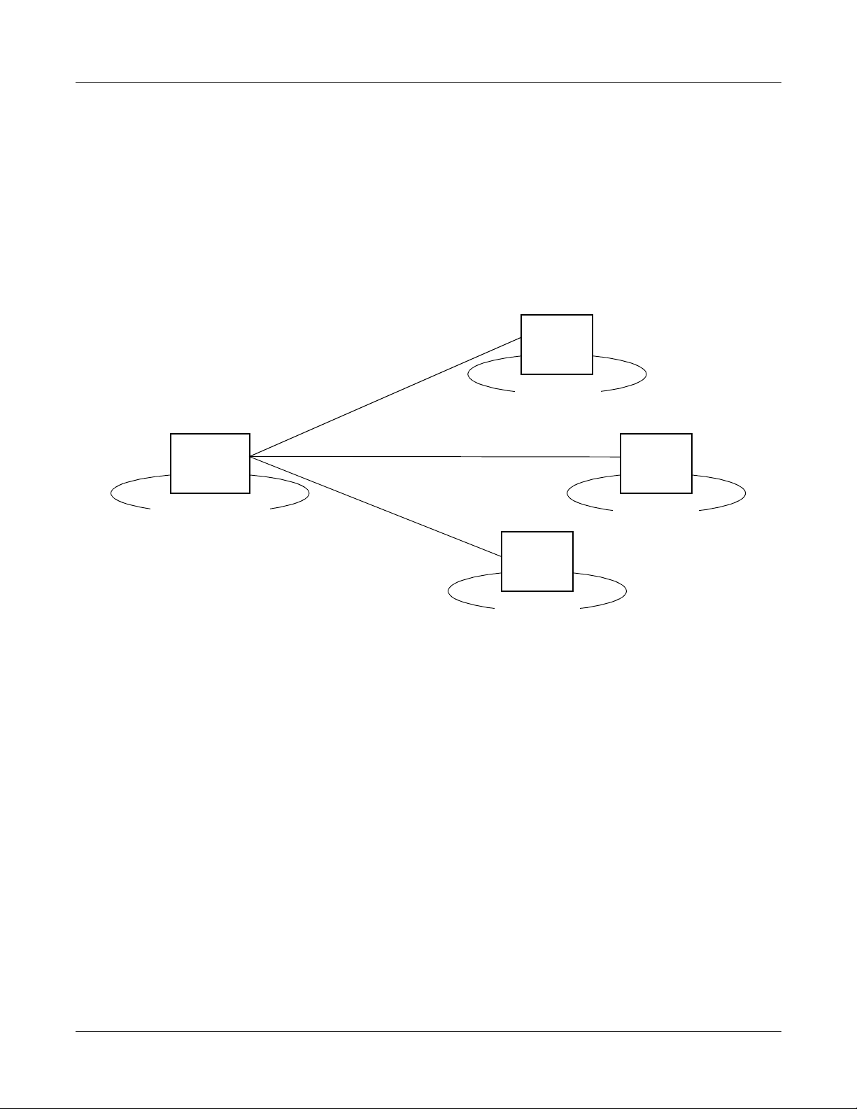
SYSTEM OUTLINE
Remote PIMs can be installed separately at the distance in one building, or between the offices
via the Public Switching Telephone Network (PSTN).
The customers in the Remote Site can use the same service features as in the Main Site.
Remote PIMs are connected to the Main Site by T1 (1.5 Mbps ) / E1 (2 Mb ps) digital interface.
Figure 1-1 Outline of Remote PIM System
PIM
PIM
OFFICE A
(MAIN SITE)
)
1
E
(
M
/ 2
)
1
T
(
M
.5
1
)
1
E
(
M
2
/
)
1
T
(
M
5
.
1
1
.
5
M
(
T
1
)
/
2
M
(
E
1
)
OFFICE B
(REMOTE SITE)
PIM
OFFICE C
(REMOTE SITE)
PIM
OFFICE D
(REMOTE SITE)
Page 4 ND-70917 (E), Issue 1.0
NEAX2000 IVS2 Remote PIM System Manual
Page 13
CHAPTER 1 GENERAL INFORMATION
PIM Configuration
PIM CONFIGURATION
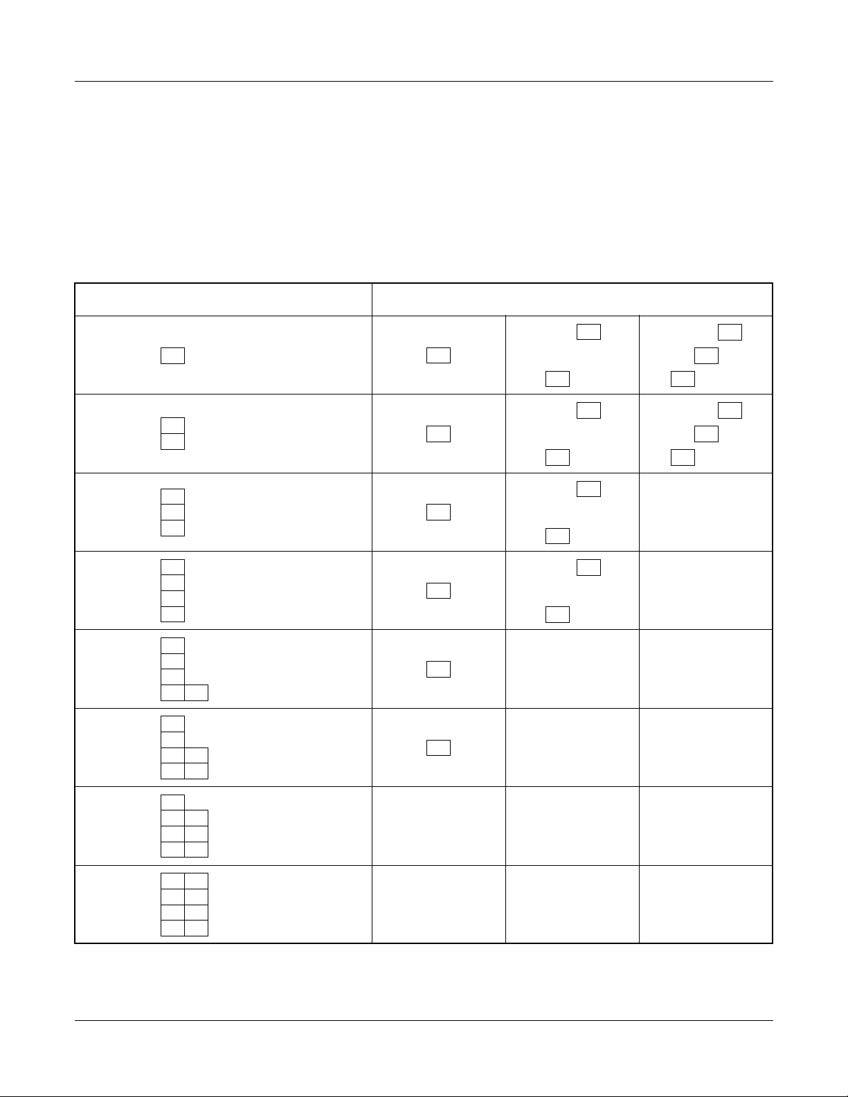
One PIM can be installed respectively as a Remote Site. A maximum of three Remote Sites can
be provided. The number of Remote Sites determines the number of PIMs in one system.
Tabl e 1- 1 shows the available PIM configuration for the Remote PIM System.
Table 1-1 PIM Configuration
NUMBER OF PIM AT MAIN SITE AVAILABLE NUMBER OF REMOTE SITE
1 PIM
(1 FP)
2 PIM
(1 FP)
3 PIM
(2 FP)
4 PIM
(2 FP)
5 PIM
(3 FP)
6 PIM
(3 FP)
123
123
12 –
12 –
1––
1––
7 PIM
(4 FP)
8 PIM
–––
–––
(4 FP)
NEAX2000 IVS2 Remote PIM System M anual
ND-70917 (E), Issue 1.0
Page 5
Page 14
CHAPTER 1 GENERAL INFORMATION
System Configuration
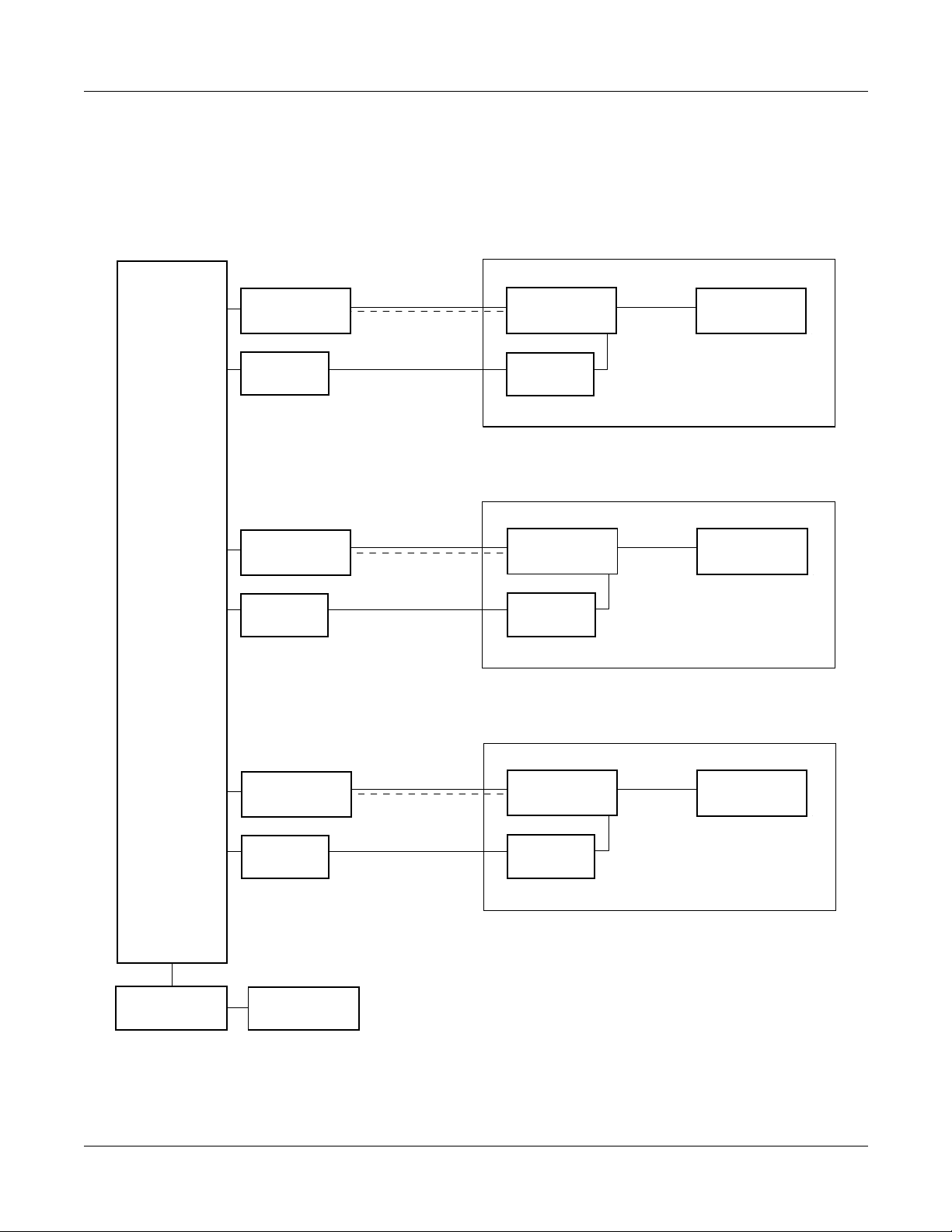
SYSTEM CONFIGURATION
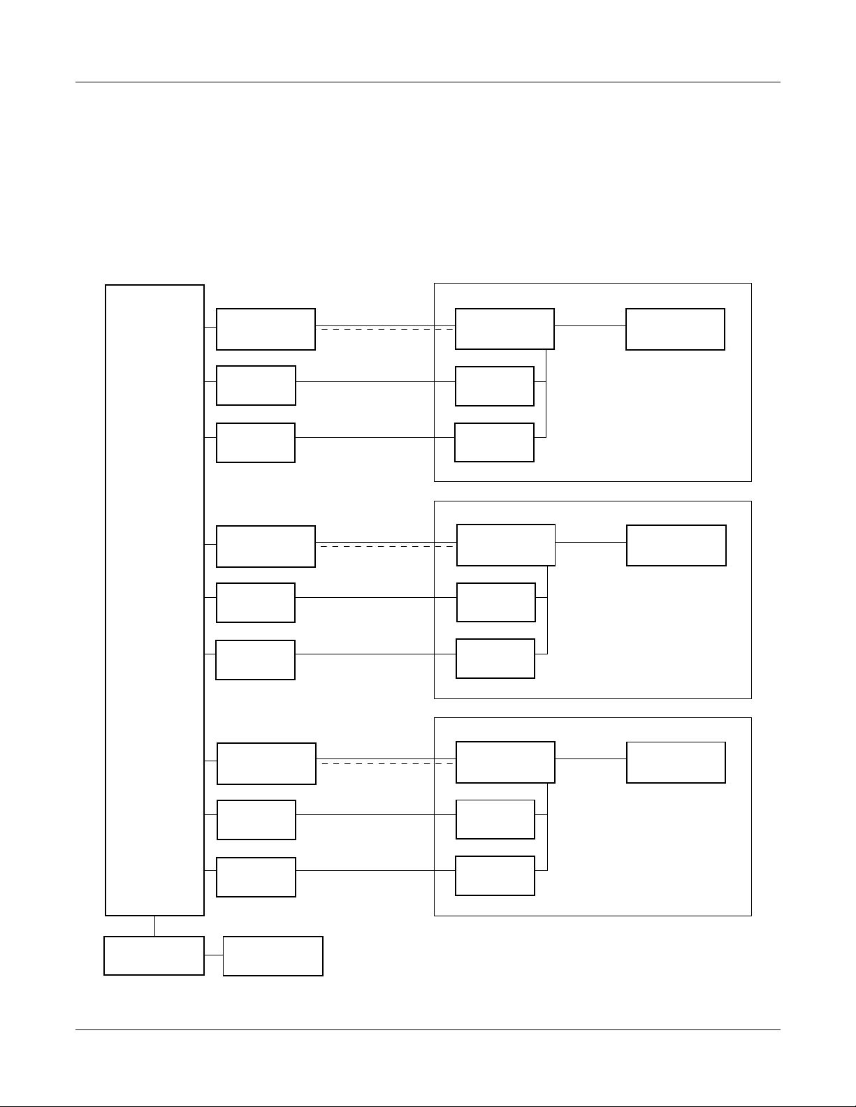
System Configuration for T1
Figure 1-2 shows the system configuration for T1.
Figure 1-2 System Configuration for T1
Remote SiteMain Site
Remote PIM1
TDSW
DAIA 1
(FP1)
DAIC 1
DAIC 2
DAIA 2
(FP1)
DAIC 3
DAIC 4
23 B Channel
1 D Channel
24 B Channel
24 B Channel
23 B Channel
1 D Channel
24 B Channel
24 B Channel
DAIB
(FP1)
DAIC 1
DAIC 2
DAIB
(FP2)
DAIC 3
DAIC 4
Line/TRK
Remote PIM2
Line/TRK
Remote PIM3
MP
DAIA 3
(FP1)
DAIC 5
DAIC 6
FP0
23 B Channel
1 D Channel
24 B Channel
24 B Channel
NEAX2000 IVS2 Remote PIM System Manual
DAIB
(FP3)
DAIC 5
DAIC 6
Line/TRK
Page 6 ND-70917 (E), Issue 1.0
Page 15
System Configuration for E1
Figure 1-3 shows the system configuration for E1.
Figure 1-3 System Configuration for E1
CHAPTER 1 GENERAL INFORMATION
System Configuration
Remote SiteMain Site
Remote PIM1
TDSW
DAID 1
(FP1)
DAIF 1
DAID 2
(FP2)
DAIF 2
30 B Channel
1 D Channel
30 B Channel
30 B Channel
1 D Channel
30 B Channel
DAIE
(FP1)
DAIF 1
DAIE
(FP2)
DAIF 2
Line/TRK
Remote PIM2
Line/TRK
Remote PIM3
DAID 3
(FP3)
DAIF 3
MP
NEAX2000 IVS2 Remote PIM System M anual
ND-70917 (E), Issue 1.0
FP0
30 B Channel
1 D Channel
30 B Channel
DAIE
(FP3)
DAIF 3
Line/TRK
Page 7
Page 16

CHAPTER 1 GENERAL INFORMATION
Required Equipment
REQUIRED EQUIPMENT
Tabl e 1- 2 shows the required equipment for providing the Remote PIM System.
Table 1-2 Required Equipmen t
EQUIPMENT
NAME
PN-DAIA DAI T1 Digital Trunk Interface (23B + D, 1.5 Mbps) Card for
PN-DAIB DAI T1 Digital Trunk Interface (23B + D, 1.5 Mbps) Card for
PN-DAIC DAI T1 Digital Trunk Interface (23B + D , 1.5 Mbps) Channel
FUNCTIONAL
NAME
FUNCTION
Remote PIM
Accommodates 24-channel PCM digital lines, and provides
Firmware Processor and BUS interface
One through thr ee cards must be provided at the Main Site,
which corresponds to the number of the Remote Site.
Remote PIM
Accommodates 24-channel PCM digital lines, and provides
Firmware Processor
One card is required per Remote PIM at the Remote Site.
Expansion Card
Accommodates 24-channel PCM digital lin es
One through six cards can be provided at the Main Site.
Two cards can be provided at the Remote Site.
PN-DAID DAI E1 Digital Trunk Interface (2 Mbps) Card f or Remote PIM
Accommodates 30-channel PCM digital lines and provides
Firmware Processor and BUS interface
One though three cards must be provided at the Main Site,
which corresponds to the number of the Remote Site.
PN-DAIE DAI E1 Digital Trunk Interface (2 Mbps) Card f or Re mote PIM
Accommodates 30-channel PCM digital lines and provides
Firmware Processor
One card is required per Remote PIM at the Remote Site.
PN-DAIF DAI E1 Digit al Trunk Interface (2 Mbps) Channel Expansion Card
Accommodates 30-channel PCM digital lin es
One through three cards can be provided at the Main Site.
One card can be provided at the Remote Site.
Page 8 ND-70917 (E), Issue 1.0
NEAX2000 IVS2 Remote PIM System Manual
Page 17

CHAPTER 1 GENERAL INFORMATION
Table 1-2 Required Equipment (Continued)
Required Equipment
EQUIPMENT
NAME
FUNCTIONAL
NAME
PN-CP15 FP Firmware Processor Card
Provides Line/Trunk interface, Memory (RAM 768 KB), and
inter-module BUS interface. BUS interface functions as a
driver/receiver of various signals, adjusts gate delay timing
and cable delay timing, monitors I/O BUS and PCM BUS.
When the system consists of three or more PIMs , one each of
this card is mounted respectively in PIM0, PIM2, PIM4, and
PIM6.
For Remote PIM System, the FP card must be mounted on
PIM0 at the Main Site, even if the system is 1-PIM/2-PIM
configuration.
PN-M10 M10 Optical Interface Card
Provides internal optical modem to T1 /E1 netw ork or Remo te
PIM
Line length: 10 km (6.25 miles) or less
Line coding: CMI
FUNCTION
RMT BUS
CA-A
17-TW-0.3
CONN CA-A
48-TW-0.2
CONN CA
– 0.6 m (2 ft.) PCM Signal Cable
Used for connecting between the DAIA/DAID card and the
BUS connector on the PIM BWB
– 0.3 m (1 ft.) Connecti on Cable Between the DAIA/DAID cards
Required when multiple DAIA/DAID cards are mounted in a
PIM at the Main Site
– 0.2 m (0.7 ft.) Connection Cable
Used for the following connection between the c ards:
• DAIA-DAIC
• DAIB-DAIC
• DAIC-DAIC
• DAID-DAIF
• DAIE-DAIF
NEAX2000 IVS2 Remote PIM System M anual
ND-70917 (E), Issue 1.0
Page 9
Page 18

CHAPTER 1 GENERAL INFORMATION
System Capacity
SYSTEM CAPACITY
System Capacity for T1
Table 1-3 shows the system capacity for T1.
Table 1-3 System Capacity for T1
CAPACITY
DESCRIPTION
MAIN PIM REMOTE PIM
DAIA card 3 –
DAIB card – 1
DAIC card 6 2
REMARKS
Line/Trunk Ports
on Remote Site
Number of PIM 1/2 3 Number of PIM depends on
NOTE 1: One port is used for the control signaling channel.
NOTE 2: When the Main Site consists of 7 or 8 PIM s, Re m ote PIM cannot be provided.
–24
NOTE 1
48
NOTE 1
64
NOTE 1
3/4 2
5/6 1
7/8 0
NOTE 2
Main PIM : 1 DAIA
Remote PIM: 1 DAIB
Main PIM : 1 D AIA, 1 DAIC
Remote PIM: 1 DAIB, 1 DAIC
Main PIM : 1 D AIA, 2 DAIC
Remote PIM: 1 DAIB, 2 DAIC
the number of Main PIM and
Remote PIM.
See "PIM Configuration" on
Page 5.
Page 10 ND-70917 (E), Issue 1.0
NEAX2000 IVS2 Remote PIM System Manual
Page 19

System Capacity for E1
Table 1-4 shows the system capacity for E1.
Table 1-4 System Capacity for E1
CAPACITY
DESCRIPTION
MAIN PIM REMOTE PIM
DAID card 3 –
DAIE card – 1
DAIF card 3 1
CHAPTER 1 GENERAL INFORMATION
System Capacity
REMARKS
Line/Trunk Ports
on Remote Site
– 30 Main PIM : 1 DAID
Remote PIM: 1 DAIE
60 Main PIM : 1 DAID, 1 DAIF
Remote PIM: 1 DAIE, 1 DAIF
Number of PIM 1/2 3 Number of PIM depends on
3/4 2
the number of Main PIM and
Remote PIM.
5/6 1
7/8 0
See "PIM Configuration" on
Page 5.
NOTE
NOTE: When the Main Site consists of 7 or 8 PIMs, Remote PIM cannot be pr ovi de d.
NEAX2000 IVS2 Remote PIM System M anual
ND-70917 (E), Issue 1.0
Page 11
Page 20

CHAPTER 1 GENERAL INFORMATION
System Conditions
SYSTEM CONDITIONS
• Only one PIM configuration is available at the Remote Site.
• Remote PIM can be installed at a maxim um of 400 m (1312 ft.) di stance from the M ain Site.
Using the Optical In ter face card (PN-M10) or line extension equipment (Repeater, MUX,
etc.), the distance can be extended.
• At the Remote Site, the line/trunk cards can be used as same as the Main Site.
For North America, the lin e/trunk cards , e x cept the CSI card for wireless sys tem according
to UTAM regulation, can be used.
• The application processor card s cannot be use d at the Remot e Site. When y ou pro vide the
ILC or CSI card to the Remote Si te, the ICH or CSH card m ust be installed on the Main Site.
• For Remote PIM System, th e install ation proce dures f o r modules , circuit ca rds , and peripheral equipment are the same as those for the regular system, except the DAI cards installation and the BUS cable connection.
Refer to the Installation Procedure Manual for detailed information.
• When the link between the Main Site and Remote Site has been lost due to power failure or
PCM Frame Loss, the system activates the Power F a ilu re Transfe r (PFT) automatica l ly on
the Remote Site, if provided.
• The Resident System Programming cannot be set to the Remote Site while the Main Site
can be set.
• If ILC or COTB card is mounted in Remo te PIM, the T1 link be tween main and Remot e Sites
must be configured as 64 Kbps with ESF and B8ZS.
Page 12 ND-70917 (E), Issue 1.0
NEAX2000 IVS2 Remote PIM System Manual
Page 21
CHAPTER 1 GENERAL INFORMATION
Time Slot Allocation
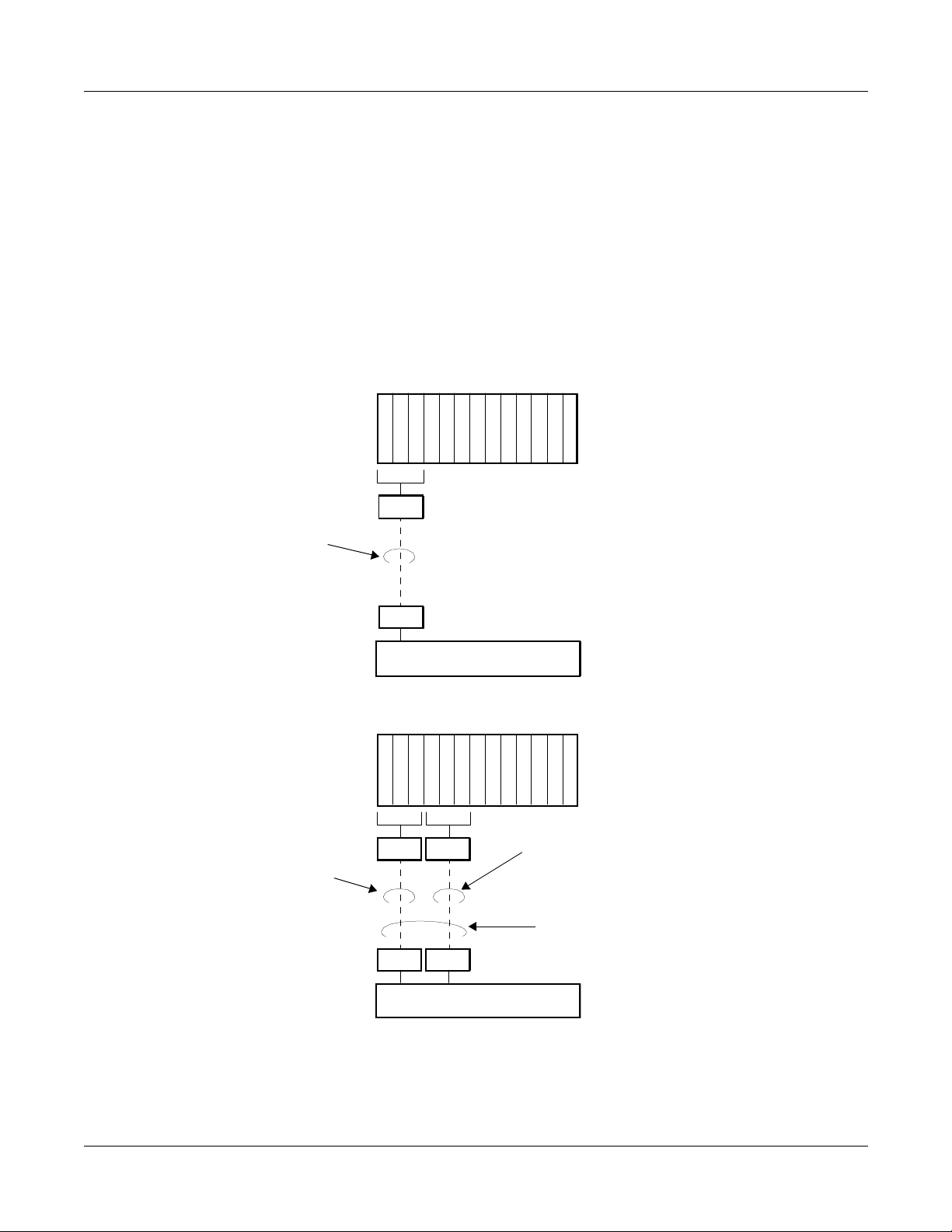
TIME SLOT ALLOCATION
Time Slot Allocation for T1
One time slot out of the last 24 ti me slots pr ovi ded b y DAIA-DAIB conne ction is u sed f or t he control signaling channel. Figure 1-4 shows the examples of time slot allocation when mounting 8port cards to the PIM.
Figure 1-4 Time Slot Allocation for T1 (1 of 2)
(a) When using 1 DAIA card and 1 D AIB card
LT00
LT01
LT02
LT03
LT04
LT05
LT06
LT07
LT08
LT09
LT10
Remote PIM
LT11
Highway Channel
• 23 Time Slots for Line/Trunks
00-23
DAIB
• 1 Time Slot for Control Signa li ng
Channel NOTE
DAIA
Main PIM
TDSW
(b) When using 1 DAIA card, 1 DAIB card and 2 DAIC cards
LT00
LT01
LT02
LT03
LT04
LT05
LT06
LT07
LT08
LT09
LT10
Remote PIM
Highway Channel
• 24 Time Slots for Line/Trunks
00-23
DAIC
24-47
DAIB
LT11
• 23 Time Slots for Line/Trunks
• 1 Time Slot for Control Signaling
Channel NOTE
• Max. 47 Time Slots for Line/Trunks
per Remote Site
DAIC
Main PIM
DAIA
TDSW
NOTE: Control signaling channel is set by SW2 of DAIA/DAIB card.
See CHAPTER 4 for the switch settings.
NEAX2000 IVS2 Remote PIM System M anual
ND-70917 (E), Issue 1.0
Page 13
Page 22
CHAPTER 1 GENERAL INFORMATION
Time Slot Allocation
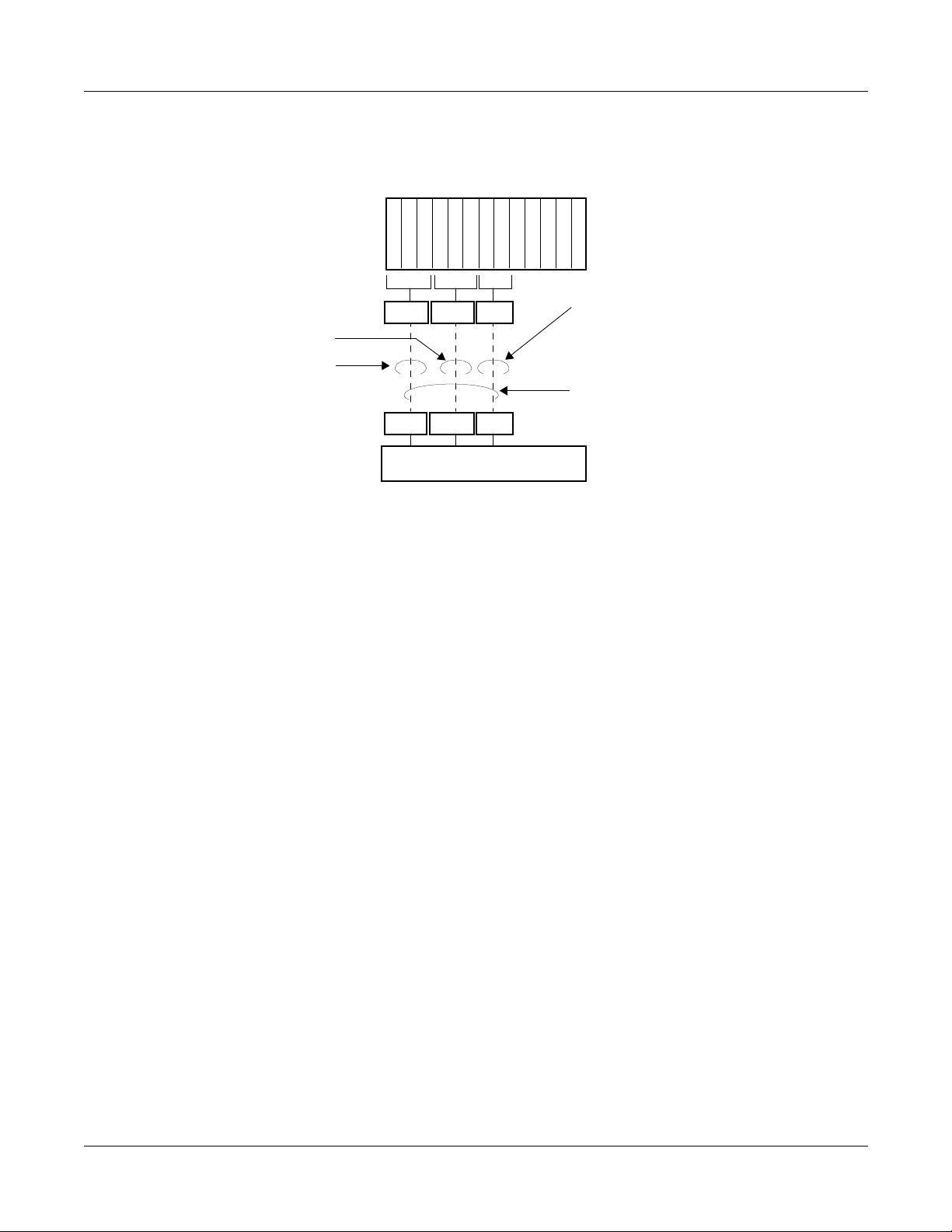
Figure 1-4 Time Slot Allocation for T1 (2 of 2)
(c) When using 1 DAIA card, 1 DAIB card and 4 DAIC cards
LT00
LT01
LT02
LT03
LT04
LT05
LT06
LT07
LT08
LT09
Remote PIM
LT10
LT11
Highway Channel
00-23 24-47 48-63
• 23 Time Slots for Line/Trunks
DAIC 0 DAIC 1 DAIB
• 24 Time Slots for Line/Trunks
• 1 Time Slot for Control Signaling
Channel NOTE
• 24 Time Slots for Line/Trunks
• Max. 63 Time Slots for Line/Trunks
per Remote Site
DAIC 0 DA IC 1 DAIA
Main PIM
TDSW
NOTE: Control signaling channel is set by SW2 of DAIA/DAIB card.
See CHAPTER 4 for the switch settings.
Page 14 ND-70917 (E), Issue 1.0
NEAX2000 IVS2 Remote PIM System Manual
Page 23
CHAPTER 1 GENERAL INFORMATION
Time Slot Allocation
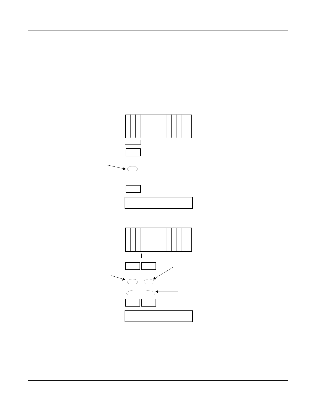
Time Slot Allocation for E1
One time slot out o f the la st 32 time sl ots pro vided b y DAID-DAIE co nnection is used for the control signaling chan nel. Figure 1-5 shows examples of time slot allocation when mounting 8-port
cards to the PIM.
Figure 1-5 Time Slot Allocation for E1
(a) When using 1 DAID card and 1 DAIE card
LT00
LT01
LT02
LT03
LT04
LT05
LT06
LT07
LT08
LT09
LT10
Remote PIM
LT11
Highway Channel
• 30 Time Slots for Line/Trunks
00-29
DAIE
• 1 Time Slot for Control Signaling
Channel NOTE
DAID
Main PIM
TDSW
(b) When using 1 DAID card, 1 DAIE card and 2 DAIF cards
LT00
LT01
LT02
LT03
LT04
LT05
LT06
LT07
LT08
LT09
LT10
Remote PIM
Highway Channel
• 30 Time Slots for Line/Trunks
00-29
DAIF
30-59
DAIE
LT11
• 30 Time Slots for Line/Trunks
• 1 Time Slot for Control Signaling
Channel NOTE
• Max. 60 Time Slots for Line/Trunks
per Remote Site
DAIF
Main PIM
DAID
TDSW
NOTE: Control signaling channel is set by SW2 of DAID/DAIE card.
See CHAPTER 4 for the switch settings.
NEAX2000 IVS2 Remote PIM System M anual
ND-70917 (E), Issue 1.0
Page 15
Page 24

This page is for your notes.
Page 16 ND-70917 (E), Issue 1.0
NEAX2000 IVS2 Remote PIM System Manual
Page 25

CHAPTER 2
INSTALLATION
This chapter explains how to install the Remote PIM ha rdware. This
chapter describes only the installati on procedures requ ired for the Remote PIM System. Refer to the Installation Procedure Manual for
general installation procedures.
NEAX2000 IVS2 Remote PIM System M anual
ND-70917 (E), Issue 1.0
Page 17
Page 26
CHAPTER 2 INSTALLATION
Precautions
PRECAUTIONS
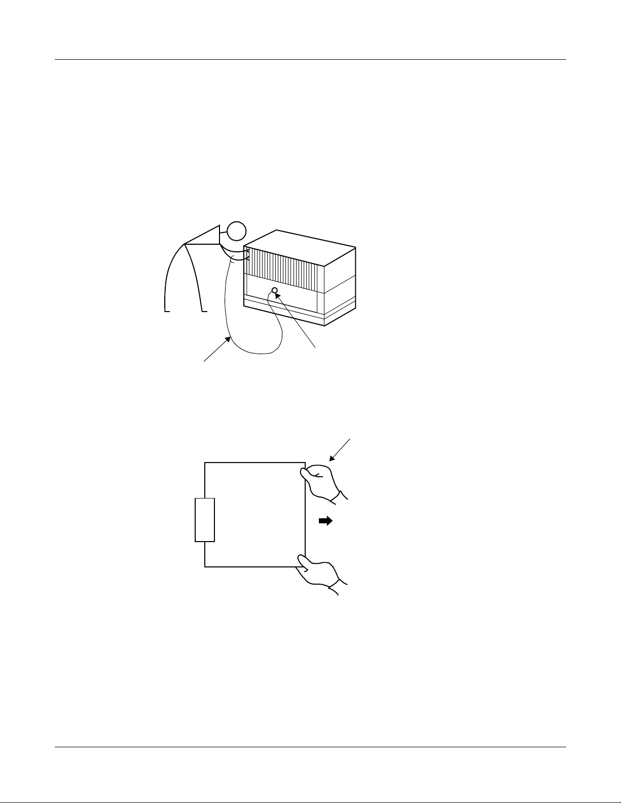
Static Electricity Guard
You must wear a grounded wrist strap to protect circuit cards from static electricity.
Figure 2-1 Static Electricity Guard (1 of 2)
• WHEN PLUGGING/UNPLUGGING A CIRCUIT CARD
PBX
WRIST STRAP
• WHEN HOLDING A CIRCUIT CARD
FRAME GROUND SCREW
NEVER TOUCH THE COMPONENTS OR
SOLDERED SURFACE WITH BARE HANDS.
CARD FRONT
Page 18 ND-70917 (E), Issue 1.0
NEAX2000 IVS2 Remote PIM System Manual
Page 27
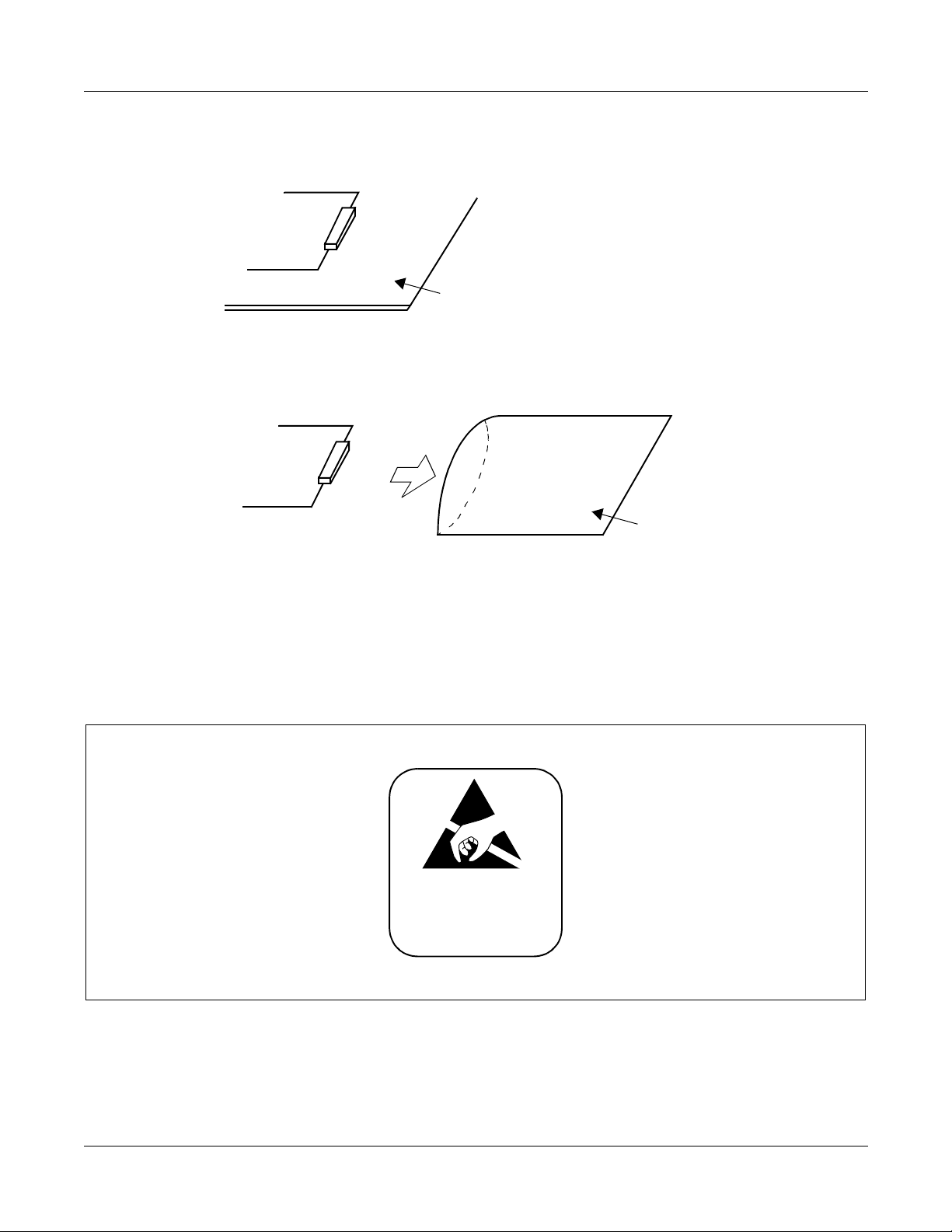
Figure 2-1 Static Electricity Guard (2 of 2)
• WHEN MAKING A SWITCH SETTING ON A CIRCUIT CARD
CIRCUIT
CARD
WEAR A WRIST STRAP AND PERFORM
THE WORK ON A GROUNDED
CONDUCTIVE WORK SURFACE.
• WHEN CARRYING A CIRCUIT CARD
CHAPTER 2 INSTALLATION
Precautions
CIRCUIT
CARD
CONDUCTIVE
POLYETHYLENE
BAG
WHEN CARRYING A CIRCUIT CARD
AROUND, KEEP THE CARD IN A
CONDUCTIVE POLYETHYLENE BAG.
The mark shown below is attached to the sheet for the work in which circuit cards are handled.
When engaging in such work, the installer must be careful not to cause damage by static electricity.
ATTENTION
Contents
Static Sensitive
Handling
Precautions Required
NEAX2000 IVS2 Remote PIM System M anual
ND-70917 (E), Issue 1.0
Page 19
Page 28
CHAPTER 2 INSTALLATION
Precautions
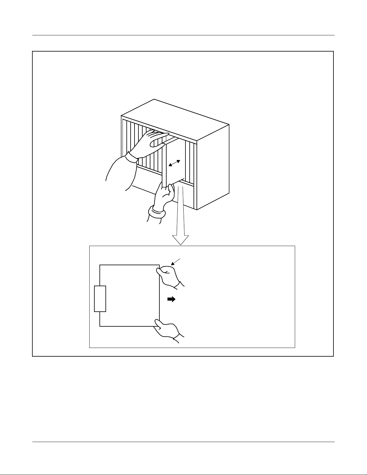
CAUTION
You must hold the edge of a circuit card when plugging or unplugging the circuit card. If you
touch another area, you may be exposed to hazardous voltages.
PBX
NEVER TOUCH THE COMPONENTS
OR SOLDERED SURFACE WITH
BARE HANDS.
CARD FRONT
Page 20 ND-70917 (E), Issue 1.0
NEAX2000 IVS2 Remote PIM System Manual
Page 29
CHAPTER 2 INSTALLATION
INSTALLATION PROCEDURE
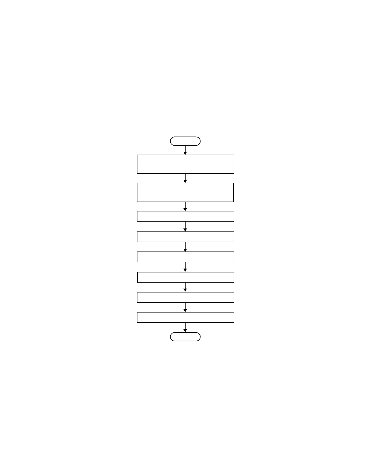
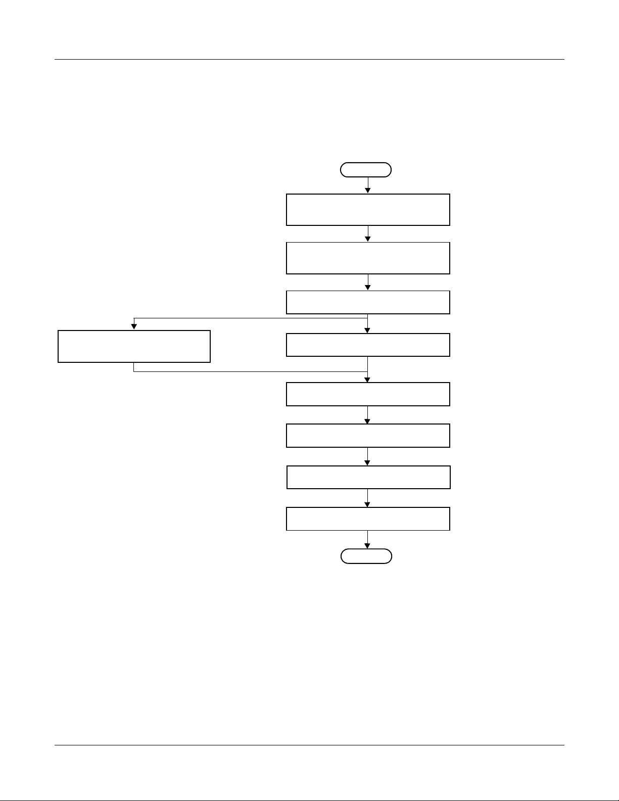
Install the Remote PIM System according to the following procedure.
Installation Procedure for Main Site
Figure 2-2 shows a flowchart of the installation procedure for the Main Site.
Figure 2-2 Installation Procedure for Main Site
START
Installation Procedu re
Mounting DAIA Card for T1 /
DAID Card for E1
Mounting DAIC Card f or T1 /
DAI F Card for E1
Mounting FP Card
Mounting M10 Card
BUS Cable Connection
DAI Connection at Main Site
Optical Cable Connection
MP Reset
NOTE 1
NOTE 2
See Page 23.
See Page 23.
See Page 23.
See Page 23.
See Page 24.
See Page 47.
See Page 51.
See Page 55.
END
NOTE 1: This procedure is required even if the Main Site is 1-PIM /2- PIM configuratio n.
NOTE 2: This procedure is required when providing PN-M10 card to connect an optical
interface.
NEAX2000 IVS2 Remote PIM System M anual
ND-70917 (E), Issue 1.0
Page 21
Page 30
CHAPTER 2 INSTALLATION
Installation Procedure
Installation Procedure for Remote Site
Figure 2-3 shows a flowchart of th e installation procedure for the Remote Site.
Figure 2-3 Installation Procedure for Remote Site
START
Mounting Line/Trunk Card
for E1
See Page 35.
Mounti ng DAIB Card for T1 /
DAIE Card for E1
Mounting D A IC C ard for T1 /
DAIF Card for E1
Mounting M10 Card
Mounting Line/Trunk Card for T1
Providing PFT
DAI Connection at Remote Site
Optical Cable Connection
NOTE 1
NOTE 2
See Pa ge 29 .
See Page 29.
See Page 29.
See Page 31.
See Pa ge 39 .
See Pa ge 50 .
See Page 51.
MP Reset
END
See Page 55.
NOTE 1: This procedure is required when providing PN-M10 card to connect an optical
interface.
NOTE 2: It is reco mmended that the Po wer Failure Trans fer (PFT) is provided o n the
Remote Site in case the link between the Main Site and the Remote Site is lost.
Page 22 ND-70917 (E), Issue 1.0
NEAX2000 IVS2 Remote PIM System Manual
Page 31

INSTALLATION FOR MAIN SITE
CHAPTER 2 INSTALLATION
Installation for Main Site
Mounting DAIA Card for T1 / DAID Card for E1
ATTENTION
Contents
Static Sensitive
(1) Before mounting the DAIA/DAID card, set the MB switch to UP position,
Handling
Precautions Required
and set the other switches to appropriate position. See CHAPTER 4.
(2) Mount the DAIA/DAID card in the AP slo ts (AP 00 -A P11) on the Main Site PIM0, 2, 4.
A maximum of three DAIA/DAID cards can be mounted.
After mounting the card, set the MB switch to DOWN position.
Mounting DAIC Card for T1 / DAIF Card for E1
(1) Before mounting the DAIC/DAIF card, set the MB switch to UP position, and set the other
switches to appropriate position. See CHAPTER 4.
(2) Mount the DAIC/DAIF card in th e AP slot s (AP00-AP11) on the Main Sit e PIM 0, 2, 4.
A maximum of six DAIC cards can be mounted.
A maximum of three D AIF cards can be mounted.
After mounting the c ard, set MB switch to DOWN position.
(3) After mounting all DAIC/DAIF cards, set MB switch on DAIA/DAID card to UP, and then
DOWN.
Mounting FP Card
(1) Before mounting th e FP card, set the MB switch to UP position, and set the other switches
to appropriate positio n. See CHAPTE R 4.
(2) Mount the FP card i n the FP slot of PIM0, PIM 2, PIM4 and PIM6.
After mounting the card, set MB switch to DOWN position.
Mounting M10 Card
(1) Confirm the correct switch settings. See CHAPTER 4.
(2) Mount the M10 card in an y one of LT slot on each PIM.
NEAX2000 IVS2 Remote PIM System M anual
ND-70917 (E), Issue 1.0
Page 23
Page 32

CHAPTER 2 INSTALLATION
Installation for Main Site
BUS Cable Connection
(1) Cable Connection Between BUS Connector on the BWB and DAIA/DAID Card
Connect the D AIA/DAID card to the BUS conne ctor on the BWB by the RMT BUS CA -A, as
shown in Figure 2-4.
In BUS connector o n the BWB , B US1B or B US0B of the e ven-numbered PIMs (PIM0, 2, 4,
etc.) must be used for this connection.
Figure 2-4 BUS Cable Connection (1 of 2)
(a) When mounting DAIA/D AID card on PIM0
• When Main PIM is 1 or 2 PIM configuration
BUS1B
BUS1A
NOTE
PCM1
PCM0
DAIA/
DAID
PIM0
BUS0B
BUS0A
• When Main PIM is 3 or 4 PIM configuration
BUS1B
BUS1A
PCM1
PCM0
DAIA/
DAID
PIM0
BUS0B
BUS0A
RMT BUS CA-A
NOTE
RMT BUS CA-A
PIM0
PIM2
PIM0
1 PIM
3 PIM
PIM0
2 PIM
PIM2
PIM0
4 PIM
NOTE: DAIA/DAID card must be mount ed in e ven-numb ered PI Ms. Wh en mounte d in
PIM0 BWB BUS connector, BUS1B or BUS0B may be used for this connection.
When mounted in PIM2 or PI M4 BWB BUS connector, BUS1B mu st be used.
Page 24 ND-70917 (E), Issue 1.0
NEAX2000 IVS2 Remote PIM System Manual
Page 33

CHAPTER 2 INSTALLATION
Figure 2-4 BUS Cable Connection (2 of 2)
Installation for Main Site
(b) When mounting DAIA/DAID card on PIM2, PIM4
NOTE
When Main PIM is 5 or 6 PIM configuration, the DAIA/DAID card must be mounted
on PIM2 and/or PIM4, and connected as follows:
BUS1B
BUS1A
PIM2/
PIM4
PCM1
PCM0
DAIA/
DAID
RMT BUS CA-A
BUS0B
BUS0A
PIM2
5 PIM
PIM2
PIM4
PIM4
6 PIM
NOTE: DAIA/DAID card must be mounted in even-numbered PIMs. When mounted in
PIM0 BWB BUS connector, BUS 1B or BUS0 B may be used for this conne ction.
When mounted in PIM2 or PIM4 BW B BUS connector, BUS1B must be used.
NEAX2000 IVS2 Remote PIM System M anual
ND-70917 (E), Issue 1.0
Page 25
Page 34

CHAPTER 2 INSTALLATION
Installation for Main Site
(2) Cable Connection Between DAIA/DAID Cards
If two or three DAIA/DAID cards are mounted on one PIM, connect between the PCM0
connector and PCM1 connector on the DAIA/DAID cards by 17-TW-0.3 CONN CA-A, as
shown in Figure 2-5.
Up to three DAIA/ DAID cards can be conne cted directly by a daisy ch ain connection on one
PIM.
Figure 2-5 DAIA/DAID Between DAIA/DAID Cable Connection
DAIA/DAID
PIM0/
PIM2/
PIM4
PCM1
PCM0
17-TW-0.3 CONN CA-A
Page 26 ND-70917 (E), Issue 1.0
NEAX2000 IVS2 Remote PIM System Manual
Page 35

CHAPTER 2 INSTALLATION
Installation for Main Site
(3) Cable Connection Between DAIA/DAID Card and DAIC/DAIF Card
Connect between the RBUS connector on the D AIC /DAIF card and the BUS connector on
the DAIA/DAID card by 48-TW-0.2 CONN CA, as shown in Figure 2-6.
Up to two DAIC cards can be mounted per DAIA card.
Only one DAIF card can be mounted per DAID card.
Figure 2-6 DAIA/DAID Between DAIC/DAIF Cable Connection (1 of 2)
• When mounting 1 DA IA/DAID card and 1 DAIC /D AIF card
DAIC
DAIA
/DAIF /DAID
: 17-TW-0.3 CONN CA-A
: 48-TW-0.2 CONN CA
TBUS
RBUS
• When mounting 2 DA IA/DAID cards and 2 DAIC/DAIF cards
DAIC DAIA
/DAIF /DAID
TBUS
RBUS
DAIC DAIA
/DAIF /DAID
BUS
PCM1
PCM0
BUS
PCM1
PCM0
NOTE
NOTE: You can mount two DAIA/DAID cards and two DAIC/DAIF cards in PIM0 or
PIM2, or one DAIA/DAID card and one DAIC/D AIF card in PIM0 and one DAIA/
DAID card and one DAIC/DAIF card in PIM2.
NEAX2000 IVS2 Remote PIM System M anual
ND-70917 (E), Issue 1.0
Page 27
Page 36

CHAPTER 2 INSTALLATION
Installation for Main Site
Figure 2-6 DAIA/DAID Between DAIC/DAIF Cable Connection (2 of 2)
• When mounting 3 DA IA/DAID cards and 3 DAIC/DAIF cards
DAIC D AIA
/DAIF /DAID
TBUS
RBUS
DAIC DAIA
/DAIF /DAID
DAIC DAIA
/DAIF /DAID
BUS
PCM1
PCM0
• When mounting 3 DAIA cards and 6 DAIC card s
DAIC DAIADAIC DAIADAIC DAIA
TBUS
RBUS
BUS
PCM1
PCM0
: 17-TW-0.3 CONN CA-A
: 48-TW-0.2 CONN CA
Page 28 ND-70917 (E), Issue 1.0
NEAX2000 IVS2 Remote PIM System Manual
Page 37

INSTALLATION FOR REMOTE SITE
CHAPTER 2 INSTALLATION
Installation for Remote Site
Mounting DAIB Card for T1 / DAIE Card for E1
ATTENTION
Contents
Static Sensitive
(1) Befo re mo un ting the DAI B/DAIE card, set the MB switch to UP position,
Handling
Precautions Required
and set the other switches to appropriate position. See CHAPTER 4.
(2) Mount the DAIB/DAIE card in the MP slot on Remote PIM.
After mounting the card, set the MB switch to DOWN position.
Mounting DAIC Card for T1 / DAIF Card for E1
(1) Before mounting the DAIC/DAIF card, set the MB switch to UP position, and set the other
switches to appropriate position. See CHAPTER 4.
(2) Mount the DAIC/DAIF card in th e AP slot s (AP00-AP11) on Remote PIM .
A maximum of two DAIC cards can be mounted per Remote PIM.
A maximum of one DAIF card can be mounted per Remote PIM.
After mounting the c ard, set MB switch to DOWN position.
(3) After mounting all DAIC/DAIF cards, set MB switch on DAIB/DAIE card to UP, and then
DOWN.
Mounting M10 Card
(1) Confirm the correct switch settings. See CHAPTER 4.
(2) Mount the M10 card in an y one of LT slot on each PIM.
NEAX2000 IVS2 Remote PIM System M anual
ND-70917 (E), Issue 1.0
Page 29
Page 38

CHAPTER 2 INSTALLATION
Installation for Remote Site
BUS Cable Connection
Connect between the BUS connector on the DAIB/DAIE card and the RBUS connector on the
DAIC/DAIF card by the 48-TW-0.2 CONN CA, as shown in Figure 2-7.
Figure 2-7 DAIB/DAIE Between DAIC/DAIF Cable Connection
• When mounting 1 DAIC/DAIF card
DAIC
/DAIF
TBUS
RBUS
48-TW-0.2 CONN CA
• When mounting 2 DAIC cards
DAIC
DAIC
TBUS
RBUS
48-TW-0.2 CONN CA
DAIB
/DAIE
BUS
DAIB
BUS
Page 30 ND-70917 (E), Issue 1.0
NEAX2000 IVS2 Remote PIM System Manual
Page 39

Mounting Line/Trunk Card for T1
(1) Mount line/trunk cards in the LT slots on the Remote PIM.
(2) Connect the l i ne cables by referring to Figure 2-8 and Table 2-1.
Figure 2-8 Mounting Location of Line/Trunk Card for T1
LT08
VM
LT00
LT01
LT02
LT03
LT04
LT05
*1
LT06
LT07
CHAPTER 2 INSTALLATION
Installation for Remote Site
LT09
LT10
LT11/FP11
MP12
PFT
LTC1
FRONT
*2
*3
LTC3
BWB
AC/DC
PWR
Remote PIM
LTC0 LTC2
DC/DC
PWR
*1 When providing only one DAIB card (Max. 23 ports): LT00~LT02 slot
*2 When providi n g one DAIB card and one D AIC ca rd (Max. 47 ports): LT00~LT05 slot
*3 When providin g one DAIB card and two DAIC cards (Max. 63 ports): LT00~LT11 slot
NOTE: One port of the last 24 ports canno t be used for line/trunk because it is used for
control signaling channel.
Table 2-1 LTC Connector Accommodation for T1
LTC CONNECTOR CARD SLOT NUMBER
LTC0 LT00~LT02
LTC1 LT03~LT05
LTC2 LT06~LT08
LTC3 LT09~LT11
NEAX2000 IVS2 Remote PIM System M anual
ND-70917 (E), Issue 1.0
Page 31
Page 40

CHAPTER 2 INSTALLATION
Installation for Remote Site
Figure 2-9 Location of Each LEN for T1
• When opposite DAIA card is set to FP No. 1:
LEN
SLOT No.
207
206
205
204
203
202
201
200
LT00 LT01 LT02 LT03 LT04 LT05 LT06 LT07 LT08 LT09 LT10 LT11
215
214
213
212
211
210
209
208
223
222
221
220
219
218
217
216
231
230
229
228
227
226
225
224
239
238
237
236
235
234
233
232
247
246
245
244
243
242
241
240
255
254
253
252
251
250
249
248
263
262
261
260
259
258
257
256
239
238
237
236
247
246
245
244
255
254
253
252
NOTE 2
• When opposite DAIA card is set to FP No. 2:
LEN
SLOT No.
407
406
405
404
403
402
401
400
LT00 LT01 LT02 LT03 LT04 LT05 LT06 LT07 LT08 LT09 LT10 LT11
415
414
413
412
411
410
409
408
423
422
421
420
419
418
417
416
431
430
429
428
427
426
425
424
439
438
437
436
435
434
433
432
447
446
445
444
443
442
441
440
455
454
453
452
451
450
449
448
463
462
461
460
459
458
457
456
439
438
437
436
447
446
445
444
455
454
453
452
NOTE 2
• When opposite DAIA card is set to FP No. 3:
LEN
SLOT No.
607
606
605
604
603
602
601
600
LT00 LT01 LT02 LT03 LT04 LT05 LT06 LT07 LT08 LT09 LT10 LT11
615
614
613
612
611
610
609
608
623
622
621
620
619
618
617
616
631
630
629
628
627
626
625
624
639
638
637
636
635
634
633
632
647
646
645
644
643
642
641
640
655
654
653
652
651
650
649
648
663
662
661
660
659
658
657
656
639
638
637
636
647
646
645
644
655
654
653
652
NOTE 2
NOTE 1: A maximum of 63 line/trunks can be accommodated in one Remote PIM.
263
262
261
260
463
462
461
460
663
662
661
660
NOTE 2: In Slot 08-11, only 4-port line/trunk cards are mountable.
When the following 8-port cards are mounted in Slot 04-07, any line/trunk cards
are not mountable in Slot 08-11.
8COT, 8DLC, 8LC, 8RSTA, 4DAT, CFTB, 2CSI, 2ILC
Page 32 ND-70917 (E), Issue 1.0
NEAX2000 IVS2 Remote PIM System Manual
Page 41

CHAPTER 2 INSTALLATION
Installation for Remote Site
Figure 2-10 LTC Connector Pin Arrangement for T1 (1 of 2)
10
11
12
13
14
15
16
17
18
19
20
21
22
23
24
25
When 8-port card
is mounted
(FP2)
/400
/401
/402
/403
/404
/405
/406
/407
/408
/409
/410
/411
/412
/413
/414
/415
/416
/417
/418
/419
/420
/421
/422
/423
(FP3)
/600
/601
/602
/603
/604
/605
/606
/607
/608
/609
/610
/611
/612
/613
/614
/615
/616
/617
/618
/619
/620
/621
/622
/623
LT00
LT01
LT02
LTC0
1
2
3
4
5
6
7
8
9
MJ
26
27
28
29
30
31
32
33
34
35
36
37
38
39
40
41
42
43
44
45
46
47
48
49
50
MN
(FP1)
LEN 200
201
202
203
204
205
206
207
208
209
210
211
212
213
214
215
216
217
218
219
220
221
222
LEN 223
When 4-port card
is mounted
(FP2)
/400
/401
/402
/403
/408
/409
/410
/411
/416
/417
/418
/419
(FP3)
/600
/601
/602
/603
/608
/609
/610
/611
/616
/617
/618
/619
(FP1)
200
201
202
203
208
209
210
211
216
217
218
219
LT00
LT01
LT02
10
12
13
14
15
16
17
18
19
20
21
22
23
24
25
11
When 8-port card
is mounted
LTC1
1
2
3
4
5
6
7
8
9
MJ
26
27
28
29
30
31
32
33
34
35
36
37
38
39
40
41
42
43
44
45
46
47
48
49
50
MN
(FP1)
LEN 224
225
226
227
228
229
230
231
232
233
234
235
236
237
238
239
240
241
242
243
244
245
246
LEN 247
(FP2)
/424
/425
/426
/427
/428
/429
/430
/431
/432
/433
/434
/435
/436
/437
/438
/439
/440
/441
/442
/443
/444
/445
/446
/447
(FP3)
/624
/625
/626
/627
/628
/629
/630
/631
/632
/633
/634
/635
/636
/637
/638
/639
/640
/641
/642
/643
/644
/645
/646
/647
LT03
LT04
LT05
When 4-port card
is mounted
(FP1) (FP2) (FP3)
224
225
226
227
232
233
234
235
240
241
242
243
/424
/425
/426
/427
/432
/433
/434
/435
/440
/441
/442
/443
/624
/625
/626
/627
/632
/633
/634
/635
/640
/641
/642
/643
LT03
LT04
LT05
NEAX2000 IVS2 Remote PIM System M anual
ND-70917 (E), Issue 1.0
Page 33
Page 42

CHAPTER 2 INSTALLATION
Installation for Remote Site
Figure 2-10 LTC Connector Pin Arrangement for T1 (2 of 2)
10
12
13
14
15
16
17
18
19
20
21
22
23
24
25
11
When 8-port card
is mounted
(FP2)
/448
/449
/450
/451
/452
/453
/454
/455
/456
/457
/458
/459
/460
/461
/462
/463
/436
/437
/438
/439
(FP3)
/648
/649
/650
/651
/652
/653
/654
/655
/656
/657
/658
/659
/660
/661
/662
/663
/636
/637
/638
/639
LT06
LT07
LTC2
1
26
2
27
3
28
4
29
5
30
6
31
7
32
8
33
9
34
35
36
37
38
39
40
41
42
43
44
45
46
47
48
49
MJ
50
MN
(FP1)
LEN 248
249
250
251
252
253
254
255
256
257
258
259
260
261
262
263
236
237
238
LEN 239
When 4-port card
is mounted
(FP2)
/448
/449
/450
/451
/456
/457
/458
/459
/436
/437
/438
/439
(FP3)
/648
/649
/650
/651
/656
/657
/658
/659
/636
/637
/638
/639
(FP1)
248
249
250
251
256
257
258
259
236
237
238
239
LT06
LT07
LT08LT08
10
12
13
14
15
16
17
18
19
20
21
22
23
24
25
11
When 4-port card
is mounted
LTC3
1
26
2
27
3
28
4
29
5
30
6
31
7
32
8
33
9
34
35
36
37
38
39
40
41
42
43
44
45
46
47
48
49
MJ
50
MN
(FP1) (FP2) (FP3)
244
245
246
247
252
253
254
255
260
261
262
263
/444
/445
/446
/447
/452
/453
/454
/455
/460
/461
/462
/463
LEN
LEN
/644
/645
/646
/647
/652
/653
/654
/655
/660
/661
/662
/663
LT09
LT10
LT11
Page 34 ND-70917 (E), Issue 1.0
NEAX2000 IVS2 Remote PIM System Manual
Page 43

CHAPTER 2 INSTALLATION
Mounting Line/Trunk Card for E1
(1) Mount line/trunk cards in the LT slots on the Remote PIM.
(2) Connect the l i ne cables by referring to Figure 2-11 and Table 2-2.
Figure 2-11 Mounting Location of Line/Trunk Card for E1
LT08
VM
LT00
LT01
LT02
LT03
LT04
LT05
*1
LT06
LT07
Installation for Remote Site
LT09
LT10
LT11/FP11
MP12
PFT
*2
LTC3
Remote PIM
AC/DC
PWR
DC/DC
PWR
LTC0 LTC2
LTC1
BWB
FRONT
*1 When providing only one DAIE card (Max. 30 ports): LT00~LT03 slot
*2 When providi ng one D AIE card and one DAIF card (Max. 60 ports): LT00~LT11 slot
Table 2-2 LTC Connector Accommodation for E1
LTC CONNECTOR CARD SLOT NUMBER
LTC0 LT00~LT02
LTC1 LT03~LT05
LTC2 LT06~LT08
LTC3 LT09~LT11
NEAX2000 IVS2 Remote PIM System M anual
ND-70917 (E), Issue 1.0
Page 35
Page 44

CHAPTER 2 INSTALLATION
Installation for Remote Site
Figure 2-12 Location of Each LEN for E1
• When opposite DAID card is set to FP No. 1:
247
246
245
244
243
242
241
240
LEN
SLOT No.
207
206
205
204
203
202
201
200
LT00 LT01 LT02 LT03 LT04 LT05 LT06 LT07 LT08 LT09 LT10 LT11
215
214
213
212
211
210
209
208
223
222
221
220
219
218
217
216
231
230
229
228
227
226
225
224
239
238
237
236
235
234
233
232
• When opposite DAID card is set to FP No. 2:
LEN
SLOT No.
407
406
405
404
403
402
401
400
LT00 LT01 LT02 LT03 LT04 LT05 LT06 LT07 LT08 LT09 LT10 LT11
415
414
413
412
411
410
409
408
423
422
421
420
419
418
417
416
431
430
429
428
427
426
425
424
439
438
437
436
435
434
433
432
447
446
445
444
443
442
441
440
• When opposite DAID card is set to FP No. 3:
647
646
645
644
643
642
641
640
LEN
SLOT No.
607
606
605
604
603
602
601
600
LT00 LT01 LT02 LT03 LT04 LT05 LT06 LT07 LT08 LT09 LT10 LT11
615
614
613
612
611
610
609
608
623
622
621
620
619
618
617
616
631
630
629
628
627
626
625
624
639
638
637
636
635
634
633
632
255
254
253
252
251
250
249
248
455
454
453
452
451
450
449
448
655
654
653
652
651
650
649
648
263
262
261
260
259
258
257
256
463
462
461
460
459
458
457
456
663
662
661
660
659
658
657
656
239
238
237
236
439
438
437
436
639
638
637
636
247
246
245
244
447
446
445
444
647
646
645
644
255
254
253
252
NOTE 2
455
454
453
452
NOTE 2
655
654
653
652
NOTE 2
263
262
261
260
463
462
461
460
663
662
661
660
NOTE 1: A maximum of 60 line/trunks can be accommodated in one Remote PIM.
NOTE 2: In Slot 08-11, only 4-port line/trunk cards are mountable.
When the following 8-port cards are mounted in Slot 04-07, any line/trunk cards
are not mountable in Slot 08-11.
8COT, 8DLC, 8LC, 8RSTA, 4DAT, CFTB, 2CSI, 2ILC
Page 36 ND-70917 (E), Issue 1.0
NEAX2000 IVS2 Remote PIM System Manual
Page 45
CHAPTER 2 INSTALLATION
Installation for Remote Site
Figure 2-13 LTC Connector Pin Arrangement for E1 (1 of 2)
10
11
12
13
14
15
16
17
18
19
20
21
22
23
24
25
When 8-port card
is mounted
(FP2)
/400
/401
/402
/403
/404
/405
/406
/407
/408
/409
/410
/411
/412
/413
/414
/415
/416
/417
/418
/419
/420
/421
/422
/423
(FP3)
/600
/601
/602
/603
/604
/605
/606
/607
/608
/609
/610
/611
/612
/613
/614
/615
/616
/617
/618
/619
/620
/621
/622
/623
LT00
LT01
LT02
LTC0
1
2
3
4
5
6
7
8
9
MJ
26
27
28
29
30
31
32
33
34
35
36
37
38
39
40
41
42
43
44
45
46
47
48
49
50
MN
(FP1)
LEN 200
201
202
203
204
205
206
207
208
209
210
211
212
213
214
215
216
217
218
219
220
221
222
LEN 223
When 4-port card
is mounted
(FP2)
/400
/401
/402
/403
/408
/409
/410
/411
/416
/417
/418
/419
(FP3)
/600
/601
/602
/603
/608
/609
/610
/611
/616
/617
/618
/619
(FP1)
200
201
202
203
208
209
210
211
216
217
218
219
LT00
LT01
LT02
10
12
13
14
15
16
17
18
19
20
21
22
23
24
25
11
When 8-port card
is mounted
LTC1
1
2
3
4
5
6
7
8
9
MJ
26
27
28
29
30
31
32
33
34
35
36
37
38
39
40
41
42
43
44
45
46
47
48
49
50
MN
(FP1)
LEN 224
225
226
227
228
229
230
231
232
233
234
235
236
237
238
239
240
241
242
243
244
245
246
LEN 247
(FP2)
/424
/425
/426
/427
/428
/429
/430
/431
/432
/433
/434
/435
/436
/437
/438
/439
/440
/441
/442
/443
/444
/445
/446
/447
(FP3)
/624
/625
/626
/627
/628
/629
/630
/631
/632
/633
/634
/635
/636
/637
/638
/639
/640
/641
/642
/643
/644
/645
/646
/647
LT03
LT04
LT05
When 4-port card
is mounted
(FP1) (FP2) (FP3)
224
225
226
227
232
233
234
235
240
241
242
243
/424
/425
/426
/427
/432
/433
/434
/435
/440
/441
/442
/443
/624
/625
/626
/627
/632
/633
/634
/635
/640
/641
/642
/643
LT03
LT04
LT05
NEAX2000 IVS2 Remote PIM System M anual
ND-70917 (E), Issue 1.0
Page 37
Page 46
CHAPTER 2 INSTALLATION
Installation for Remote Site
Figure 2-13 LTC Connector Pin Arrangement for E1 (2 of 2)
10
12
13
14
15
16
17
18
19
20
21
22
23
24
25
11
When 8-port card
is mounted
(FP2)
/448
/449
/450
/451
/452
/453
/454
/455
/456
/457
/458
/459
/460
/461
/462
/463
/436
/437
/438
/439
(FP3)
/648
/649
/650
/651
/652
/653
/654
/655
/656
/657
/658
/659
/660
/661
/662
/663
/636
/637
/638
/639
LT06
LT07
LTC2
1
26
2
27
3
28
4
29
5
30
6
31
7
32
8
33
9
34
35
36
37
38
39
40
41
42
43
44
45
46
47
48
49
MJ
50
MN
(FP1)
LEN 248
249
250
251
252
253
254
255
256
257
258
259
260
261
262
263
236
237
238
LEN 239
When 4-port card
is mounted
(FP2)
/448
/449
/450
/451
/456
/457
/458
/459
/436
/437
/438
/439
(FP3)
/648
/649
/650
/651
/656
/657
/658
/659
/636
/637
/638
/639
(FP1)
248
249
250
251
256
257
258
259
236
237
238
239
LT06
LT07
LT08LT08
10
12
13
14
15
16
17
18
19
20
21
22
23
24
25
11
When 4-port card
is mounted
LTC3
1
26
2
27
3
28
4
29
5
30
6
31
7
32
8
33
9
34
35
36
37
38
39
40
41
42
43
44
45
46
47
48
49
MJ
50
MN
(FP1) (FP2) (FP3)
244
245
246
247
252
253
254
255
260
261
262
263
/444
/445
/446
/447
/452
/453
/454
/455
/460
/461
/462
/463
LEN
LEN
/644
/645
/646
/647
/652
/653
/654
/655
/660
/661
/662
/663
LT09
LT10
LT11
Page 38 ND-70917 (E), Issue 1.0
NEAX2000 IVS2 Remote PIM System Manual
Page 47

Power Failur e Transfer (AUC)
The PN-AUC card can be used as the PFT card at the Remote Site.
• Figure 2-14 shows an outline of a PFT (PN-AUC) connection.
• Figure 2-15 shows the MDF cross connection for a PFT (PN-AUC).
Figure 2-14 PFT Connection Outline (AUC)
Remote PIM
CHAPTER 2 INSTALLATION
Installation for Remote Site
TEL
MDF
PN-AUC
PN-4COT
MDF
TO C.O. LINE
NEAX2000 IVS2 Remote PIM System M anual
ND-70917 (E), Issue 1.0
Page 39
Page 48

CHAPTER 2 INSTALLATION
Installation for Remote Site
Figure 2-15 MDF Cross Connection for PFT (AUC) (1 of 2)
PN-4COT
REMOTE PIM
LTC0
JP
MDF
LT00
LEN000 (No. 0)
LEN001 (No. 1)
04
03
02
01
CN1
PN-AUC
4Q-TW-0.3 CONN CA
LEN008 (No. 0)
LEN009 (No. 1)
C.O.R0
C.O.T0
C.O.R1
C.O.T1
Sta. R0
Sta. T0
Sta. R1
Sta. T1
26
27
28
29
1
2
3
4
34
10
35
1
26
2
27
3
28
4
29
9
9
34
10
35
Ring
Tip
Ring
Tip
Ring
Tip
Ring
Tip
TO
C.O. LINE
TO
C.O. LINE
TO
STATION
TO
STATION
LT01
04
03
02
01
CN1
NEAX2000 IVS2 Remote PIM System Manual
Page 40 ND-70917 (E), Issue 1.0
Page 49

CHAPTER 2 INSTALLATION
Installation for Remote Site
Figure 2-15 MDF Cross Connection for PFT (PN-AUC) (2 of 2)
LEN000
LEN001
LEN008
LEN009
LTC0 (J)
1 C.O.R0 26 C.O.T0
2 C.O.R1 27 C.O.T1
9 Sta.R0 34 Sta.T0
10 Sta.R1 35 Sta.T1
11 36
12 37
LTC0 (P)
26 C.O.T0 1 C.O.R0
27 C.O.T1 2 C.O.R1
34 Sta.T0 9 Sta.R0
35 Sta.T1 10 Sta.R1
36 11
37 12
NOTE 1: The No. 2 and No. 3 circuit in the PN-4CO T card cannot be used wit h the PFT function
NOTE 2: When usin g Ground Start tr unks with the PFT func tion, the single lin e stations must
have a ground sending but ton and a ground lead must be r un to the station.
.
NEAX2000 IVS2 Remote PIM System M anual
ND-70917 (E), Issue 1.0
Page 41
Page 50

CHAPTER 2 INSTALLATION
Installation for Remote Site
Power Fai lur e Transfer (8PFT)
The PZ-8PFTB card can be used as the PFT card at the Remote Site.
• Figure 2-16 shows an outline of a PFT (PZ-8PFTB) connection.
Figure 2-16 PFT Connection Outline (8PFT)
PZ-8PFTB
Remote PIM
TEL
MDFMDF MDF MDF
PN-8LC PN-8COT
NOTE
NOTE: Using the PN-AUC card (long line card) instead of the PN-8LC card is not
recommended due to the variations from Central Office to the PBX; line
quality cannot be assured.
TO C.O.
LINE
Page 42 ND-70917 (E), Issue 1.0
NEAX2000 IVS2 Remote PIM System Manual
Page 51

CHAPTER 2 INSTALLATION
Installation for Remote Site
• Install the PZ-8PFTB card to the PIM according to the following steps:
(1) Mount the PZ-8PFTB card into the PFT slot of the PIM.
(2) Connect the champ connectors of 25-pair cables to the PFT0 and PFT1 connectors on the
PZ-8PFTB card as shown in Figure 2-27.
Figure 2-17 Connection of 25-Pair Cable and PZ-8PFTB
PZ-8PFTB
PFT1 CONNECTOR
PFT0 CONNECTOR
CHAMP CONNECTOR ATTACHED TO PZ-8PFTB
25-PAIR CABLE
To MDF
(See (3) on Page 44.)
NEAX2000 IVS2 Remote PIM System M anual
ND-70917 (E), Issue 1.0
Page 43
Page 52

CHAPTER 2 INSTALLATION
Installation for Remote Site
(3) Connect the 25-pair cables on the MDF.
• Figure 2-18 shows the PFT connector pin assignment for each PFT circuit number
(No. 0-No. 7).
Figure 2-18 PFT Connector Pin Assignment
PFT0
1 Sta. R0 26 Sta. T0
2 8LC. R0 27 8LC. T 0
3 C.O. R0 28 C.O. T0
4 8COT. R0 29 8COT. T0
5 Sta. R1 30 Sta. T1
6 8LC. R1 31 8LC. T 1
7 C.O. R1 32 C.O. T1
8 8COT. R1 33 8COT. T1
9 Sta. R2 34 Sta. T2
10 8LC. R2 35 8LC. T2
11 C.O. R2 36 C.O. T2
12 8COT. R2 37 8COT. T2
13 Sta. R3 38 Sta. T3
14 8LC. R3 39 8LC. T3
15 C.O. R3 40 C.O. T3
16 8COT. R3 41 8COT. T3
17 Sta. R4 42 Sta. T4
18 8LC. R4 43 8LC. T4
19 C.O. R4 44 C.O. T4
20 8COT. R4 45 8COT. T4
21 Sta. R5 46 Sta. T5
22 8LC. R5 47 8LC. T5
23 C.O. R5 48 C.O. T5
24 8COT. R5 49 8COT. T5
25 50
No. 0
No. 1
No. 2
No. 3
No. 4
No. 5
PFT1
1 Sta. R6 26 Sta. T6
2 8LC. R6 27 8LC. T6
3 C.O. R6 28 C.O. T6
4 8COT. R6 29 8COT. T6
5 Sta. R7 30 Sta. T7
6 8LC. R7 31 8LC. T7
7 C.O. R7 32 C.O. T7
8 8COT. R7 33 8COT. T7
934
10 35
11 36
12 37
13 38
14 39
15 40
16 41
17 42
18 43
19 44
20 45
21 46
22 47
23 48
24 49 E
25 50 –27 V
No. 6
No. 7
Page 44 ND-70917 (E), Issue 1.0
NEAX2000 IVS2 Remote PIM System Manual
Page 53
CHAPTER 2 INSTALLATION
Installation for Remote Site
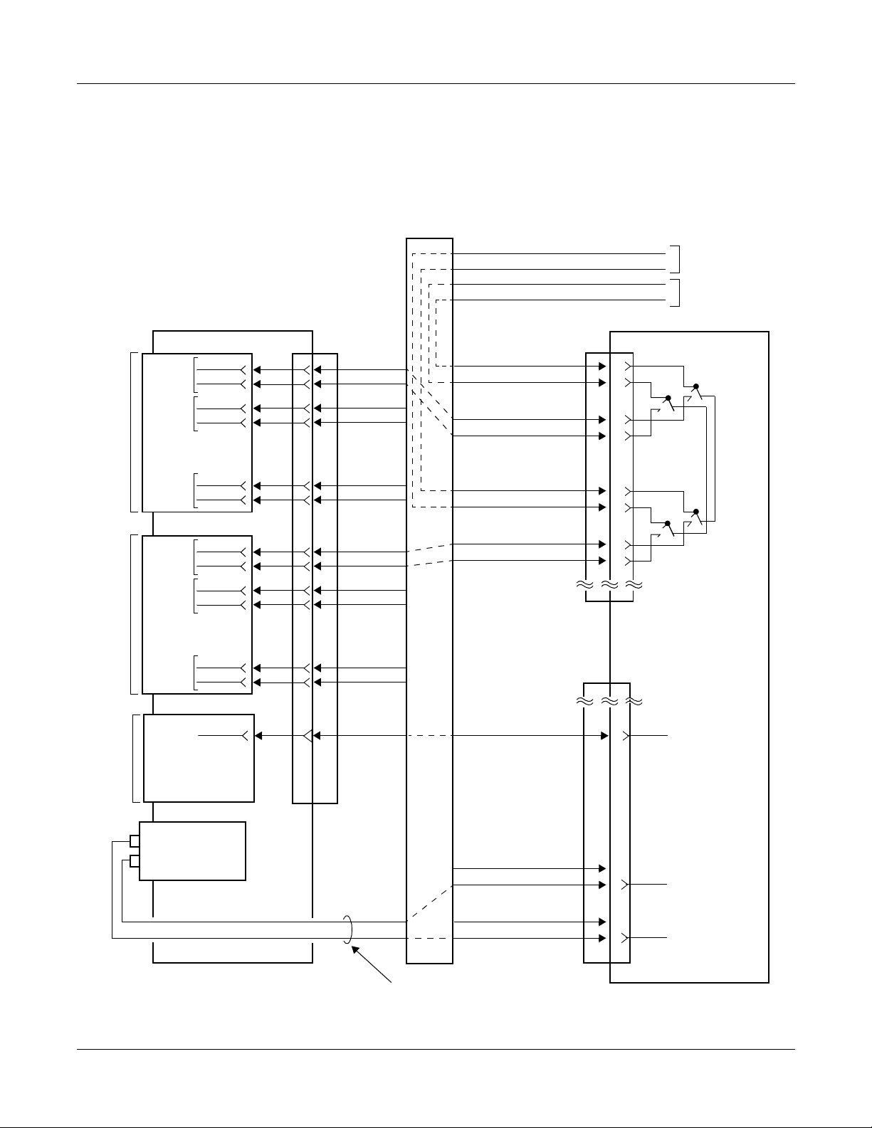
• Figure 2-19 shows an e xample of the MDF cross con nection f or the No . 0 circuit on the P FT
(PZ-8PFTB).
Figure 2-19 MDF Cross Connection for PFT (8PFT) (1 of 2)
MDF
Tip
Ring
Tip
Ring
TO C.O. LINE
TO STATION
LT00
LT01
MP
PN-8LC
LEN000
(No. 0)
LEN001
(No. 1)
•
•
•
LEN007
(No. 7)
PN-8COT
LEN008
(No. 0)
LEN009
(No. 1)
•
•
•
LEN015
(No. 7)
PN-DAIB/DAIE
REMOTE PIM
R0
T0
R1
T1
•
•
•
R7
T7
R0
T0
R1
T1
•
•
•
R7
T7
12D
LTC0
JP
1
1
26
26
2
2
27
27
•
•
•
•
•
•
8
8
33
33
9
9
34
34
10
10
35
35
•
•
•
•
•
•
16
16
41
41
25 25
Sta. R0
Sta. T0
8LC. R0
8LC. T0
C.O. R0
C.O. T0
8COT. R0
8COT. T0
1
26
2
27
3
28
4
29
PJ
23
PZ-8PFTB
PFT0
No. 0
PFT1
MJ ALM
PZ-PW121
–27 V
G
INSTALLATION CABLE
NEAX2000 IVS2 Remote PIM System M anual
ND-70917 (E), Issue 1.0
24
49
25
50
PJ
E
–27 V
Page 45
Page 54

CHAPTER 2 INSTALLATION
Installation for Remote Site
Figure 2-20 MDF Cross Connection for PFT (8PFT) (2 of 2)
1 PFT0 CONNECTOR
2 PFT1 CONNECTOR
23 MJ ALM 48
24 49 E
25 50 –27 V
3 LTC0 CONNECTOR
LEN000
PFT0 (J)
1 Sta. R0 26 Sta. T 0
2 8LC. R0 27 8LC. T0
3 C.O. R0 28 C.O. T0
4 8COT. R0 29 8COT. T0
PFT1 (J)
LTC0 (J)
1R026T0
227
328
429
PFT0 (P)
26 Sta. T0 1 Sta. R0
27 8LC. T0 2 8LC. R0
28 C.O. T0 3 C.O. R0
29 8COT. T0 4 8COT. R0
PFT1 (P)
48 23 MJ ALM
49 E 24
50 –27 V 25
LTC0 (P)
26 T0 1 R0
27 2
28 3
29 4
TO PZ-8PFTB
TO STATION
TO PN-8LC
TO C.O. LINE
TO PN-8COT
TO PN-DAIB/DAIE
TO PZ-PW121
LEN008
9R034T0
10 35
11 36
12 37
34 T0 9 R0
35 10
36 11
37 12
TO PZ-8PFTB
Page 46 ND-70917 (E), Issue 1.0
NEAX2000 IVS2 Remote PIM System Manual
Page 55

CHAPTER 2 INSTALLATION
Connection Between Main Site an d Remote Site
CONNECTION BETWEEN MAIN SITE
AND REMOTE SITE
DAI Connection at Main Site
(1) When using the LTC connector on the BWB
Connect the cable to a CSU or directly to the Remote PIM via the MDF as shown in Figure
2-21. Figure 2-22 shows an example of DAI MDF cross connection.
For the optical cable connection betw een the Main PIM and the Rem ote PIM, refe r to
"Optical Cab le Connection" on Page 51.
Figure 2-21 DAI Cable Connection via LTC Connector (Main Site)
BWB
MAIN PIM
DAIA/
DAIC/
DAID/
DAIF
LTC0/1/2/3 CONNECTOR
TWISTED-PAIR
CABLE
(SHIELD TYPE)
Max. 200 m (656 ft.)
(0.65
φ
cable)
MDF
NOTE 1
CSU
REMOTE PIM
CSU: CONNECTION
SERVICE UNIT
NOT E 1: When the Remote PIM is directly connected without CSU, maximum distance is
400 m (1312 ft.) between the Main PIM and the Remote PIM.
NOT E 2: When the DAIA/DAID card is mounted in the AP11 slot, be sure to use the CN
connector on the DAIA/DAID card. S ee (2) on Page 49.
NEAX2000 IVS2 Remote PIM System M anual
ND-70917 (E), Issue 1.0
Page 47
Page 56

CHAPTER 2 INSTALLATION
Connection Between Main Site and Remote Site
Figure 2-22 Example of DAI MDF Cr oss Connection
via LTC Connector (Main Site)
PIM 0
LTC3
JP MDFPN-DAIA/DAID
AP09
AP10
RECEIVE
RA 1 1 RA
RB 26 26 RB
TA 2 2 TA
TB 27 27 TB
1
LTC3
JPPN-DAIC/DAIF
RA 9 9 RA
RB 34 34 RB
TA 10 10 TA
TB 35 35 TB
2
SEND
RECEIVE
SEND
TO CSU/
REMOTE PIM
1 LTC3 CONNECTOR
1
RA TA26
2
3
4
27
28
29
LTC (J)
RB
TB
26
27
28
29
RB TB1
(P)
RA
2
TA
3
4
2 LTC3 CONNECTOR
9
RA TA34
10
11
12
LTC (J)
NEAX2000 IVS2 Remote PIM System Manual
35
36
37
RB
TB
34
35
36
37
RB TB9
10
11
12
(P)
RA
TA
Page 48 ND-70917 (E), Issue 1.0
Page 57

CHAPTER 2 INSTALLATION
Connection Between Main Site an d Remote Site
(2) When using the CN connector on the DAI Card
Connect the cab l e to a CSU or d i rec tly to t he R emo t e PIM via the CN connector on the
DAIA/DAIC/DAID/DAIF card as shown in Figure 2-23.
Figure 2-23 DAI Cable Connection via CN Connector (Main Site)
BWB
MAIN PIM
DAIA/
DAIC/
DAID/
DAIF
CN
DAIA/DAIC/DAID/DAIF MDF
TWISTED-PAIR
CABLE
(SHIELD TYPE)
CN
TB
4
TA
3
RB
2
RA
1
Max. 200 m (656 ft.)
(0.65
φ
cable)
MDF
NOTE
CSU
SEND
TB
TA
TO CSU/REMOTE PIM
RB
RA
REMOTE PIM
RECEIVE
CN CONNECTOR
TB
TA
RB
RA
NOTE: When the Remote PIM is directly connected without CSU, maximum distance is
400 m (1312 ft.) between the Main PIM and the Remote PIM.
NEAX2000 IVS2 Remote PIM System M anual
ND-70917 (E), Issue 1.0
Page 49
Page 58

CHAPTER 2 INSTALLATION
Connection Between Main Site and Remote Site
DAI Connection at Remote Site
Connect the cab l e to a CSU or dir ectly to the Mai n PIM v ia th e CN c onn ector on the DAIB/DAIC/
DAIE/DAIF card as shown in Figure 2-24.
Figure 2-24 DAI Cable Connection via CN Connector (Remote Site)
BWB
REMOTE PIM
DAIB/
DAIC/
DAIE/
DAIF
CN
DAIB/DAIC/DAIE/DAIF MDF
TWISTED-PAIR
CABLE
(SHIELD TYPE)
CN
TB
4
TA
3
RB
2
RA
1
Max. 200 m (656 ft.)
(0.65
φ
cable)
MDF
NOTE
SEND
TB
TA
TO CSU/MAIN PIM
RB
RA
CSU
MAIN PIM
RECEIVE
CN CONNECTOR
TB
TA
RB
RA
NOTE: When the Remote PIM is directly connected without CSU, maximum distance is
400 m (1312 ft.) between the Main PIM and the Remote PIM.
Page 50 ND-70917 (E), Issue 1.0
NEAX2000 IVS2 Remote PIM System Manual
Page 59

CHAPTER 2 INSTALLATION
Connection Between Main Site an d Remote Site
Optical Cable Connection
When using an optical cab le to estab lish the connection bet ween the Main PIM an d Remote PIM,
connect each end of the cable to the CN1 connector of the M10 cards on both sites. Two DAI
cards are connected to one M10 card, via MDF through LTC connector on the BWB or CN connector on the DAI card.
Figure 2-25 through Figure 2-27 show an outline of the connection and an example of the M10
MDF cross connection.
Figure 2-25 Outline of Optical Cable Connection
DAIA/
DAIC/
DAID/
DAIF
DAIA/
DAIC/
DAID/
DAIF
MAIN PIM
MDF
OPTICAL
M10
CN1 CN1
CABLE
Max. 10 km (6.25 miles)
M10
REMOTE PIM
MDF
DAIB/
DAIC/
DAIE/
DAIF
DAIB/
DAIC/
DAIE/
DAIF
NEAX2000 IVS2 Remote PIM System M anual
ND-70917 (E), Issue 1.0
Page 51
Page 60

CHAPTER 2 INSTALLATION
Connection Between Main Site and Remote Site
Figure 2-26 Example of M10 MDF Cross Connection via
LTC Connector (Main Site) (1 of 2)
AP09
AP10
PIM 0
LTC3
JP MDFPN-DAIA/DAID
RA 1 1 RA
RB 26 26 RB
TA 2 2 TA
TB 27 27 TB
1
LTC3
JPPN-DAIC/DAIF
RA 9 9 RA
RB 34 34 RB
TA 10 10 TA
TB 35 35 TB
RECEIVE
SEND
RECEIVE
LT05
CN1
No. 1
No. 0
2
LTC1
JPPN-M10
RA 17 17 RA
RB 42 42 RB
TA 18 18 TA
TB 43 43 TB
RA 19 19 RA
RB 44 44 RB
TA 20 20 TA
TB 45 45 TB
3
TO REMOTE PIM PN-M10 CARD
SEND
RECEIVE
SEND
RECEIVE
SEND
Page 52 ND-70917 (E), Issue 1.0
NEAX2000 IVS2 Remote PIM System Manual
Page 61

CHAPTER 2 INSTALLATION
Connection Between Main Site an d Remote Site
Figure 2-26 Example of M10 MDF Cross Connection via
LTC Connector (Main Site) (2 of 2)
1 LTC3 CONNECTOR
1
RA TA26
2
3
4
2 LTC3 CONNECTOR
9
10
11
12
27
28
29
LTC (J)
RA TA34
35
36
37
LTC (J)
RB
TB
RB
TB
26
27
28
29
34
35
36
37
RB TB1
(P)
RB TB9
10
11
12
(P)
RA
2
TA
3
4
RA
TA
3 LTC1 CONNECTOR
17
RA TA42
18
19
20
LTC (J)
NEAX2000 IVS2 Remote PIM System M anual
ND-70917 (E), Issue 1.0
43
44
45
RB
TB
42
43
44
45
RB TB17
18
19
20
(P)
RA
TA
Page 53
Page 62

CHAPTER 2 INSTALLATION
Connection Between Main Site and Remote Site
Figure 2-27 Example of M10 MDF Cross Connection
via CN Connector (Remote Site) (1 of 2)
REMOTE PIM
MDFPN-DAIB/DAIE
MP12
AP10
TB TB
TA TA
RB RB
RA
PN-DAIC/DAIF
TB
TA
RB
RA
No. 1
CN
4
3
2
1RA
1
CN
4
3
2
1
1
LTC1
JPPN-M10
RA 17 17 RA
RB 42 42 RB
TA 18 18 TA
TB 43 43 TB
RECEIVE
SEND
RECEIVE
TB
TA
RB
RA
SEND
RECEIVE
LT05
CN1
No. 0
RA 19 19 RA
RB 44 44 RB
TA 20 20 TA
TB 45 45 TB
2
TO MAIN PIM PN-M10 CARD
NEAX2000 IVS2 Remote PIM System Manual
SEND
RECEIVE
SEND
Page 54 ND-70917 (E), Issue 1.0
Page 63

CHAPTER 2 INSTALLATION
Figure 2-27 Example of M10 MDF Cross Connection
via CN Connector (Remote Site) (2 of 2)
MP Reset
1 CN CONNECTOR
TB
TA
RB
RA
2 LTC1 CONNECTOR
17
RA TA42
18
19
20
43
44
45
LTC (J)
RB
TB
42
43
44
45
RB TB17
18
19
20
(P)
RA
TA
MP RESET
After mounting all DAI cards/M10 cards and establishing the connection between the Main Site
and the Remote Site, press SW1 switch on the MP card.
NEAX2000 IVS2 Remote PIM System M anual
ND-70917 (E), Issue 1.0
Page 55
Page 64

This page is for your notes.
Page 56 ND-70917 (E), Issue 1.0
NEAX2000 IVS2 Remote PIM System Manual
Page 65

CHAPTER 3
TROUBLESHOOTING
This chapter explains the method for fault diagnosis and troubleshooting when maintenance personnel detects fault occurrences by lamp
indication on DAIA/DAIB/DAIC/DAID/DAIE/DAIF and M10 cards. For
other system faults, refer to the Maintenance Manual.
NEAX2000 IVS2 Remote PIM System M anual
ND-70917 (E), Issue 1.0
Page 57
Page 66

CHAPTER 3 TROUBLESHOOTING
Table 3-1 shows contents of the faults and the remedial action on each lamp status.
Table 3-1 Remedial Action on Each Lamp Status
CARD NAME LAMP STATUS FAULT CONTENT REMEDIAL ACTION
PN-DAIA
(DAIA)
RUN lamp is not
flashing.
Abnormal operation
of DAIA card
LINK lamp is not on. Layer 2 link connec-
tion fa i lure between
DAIA and D AIB
RED lamp is on. PCM signal loss or
Frame Alignment
signal loss
1 Reset the MB switch.
(Down→Up→Down)
2 Check the setti ng of SW1.
1: FP No. 1
2: FP No. 2
3: FP No. 3
0, 4-F: Not used
3 If the fault cannot be
cleared, replac e the card.
1 Check to see if the cable
between DAIA and DAIB is
correctly connected. Refer
to "Connection Be tween
Main Site and Remote Site"
on Page 47.
2 Reset the MB switch.
(Down→Up→Down)
Check to see if the cable
between DAIA and DAIB is correctly connected. Refer to
"Connection Between Main
Site and Remote Site" on P age
47.
RMT lamp is on. Remote alarm Check to see if the cable
between DAIA and DAIB
(sending side) is correctly connected. Refer to "Connection
Between Main Site and
Remote Site" on Page 47.
Page 58 ND-70917 (E), Issue 1.0
NEAX2000 IVS2 Remote PIM System Manual
Page 67

CHAPTER 3 TROUBLESHOOTING
Table 3-1 Remedial Action on Each Lamp Status (Continued)
CARD NAME LAMP STATUS FAULT CONTENT REMEDIAL ACTION
PN-DAIB
(DAIB)
RUN lamp is not
flashing.
Abnormal operation
of DAIB card
LINK lamp is not on. Layer 2 link connec-
tion fa i lure between
DAIA and D AIB
RED lamp is on. PCM signal loss or
Frame Alignment
signal loss
1 Reset the MB switch.
(Down→Up→Down)
2 If the fault cannot be
cleared, replac e the card.
1 Check to see if the cable
between DAIA and DAIB is
correctly connected. Refer
to "Connection Be tween
Main Site and Remote Site"
on Page 47.
2 Reset the MB switch.
(Down→Up→Down)
1 Check to see if the cable
between DAIA and DAIB is
correctly connected. Refer
to "Connection Be tween
Main Site and Remote Site"
on Page 47.
2 Reset the MB switch of
DAIA card on the Main Site.
(Down→Up→Down)
RMT lamp is on. Remote alarm Check to see if the cable
between DAIA and DAIB
(sending side) is correctly connected. Refer to "Connection
Between Main Site and
Remote Site" on Page 47.
NEAX2000 IVS2 Remote PIM System M anual
ND-70917 (E), Issue 1.0
Page 59
Page 68

CHAPTER 3 TROUBLESHOOTING
Table 3-1 Remedial Action on Each Lamp Status (Continued)
CARD NAME LAMP STATUS FAULT CONTENT REMEDIAL ACTION
PN-DAIC
(DAIC)
RUN lamp is not
flashing.
Abnormal operation
of DAIC card
LINK lamp is not on. Layer 2 link connec-
tion fa i lure between
DAIA and D AIB
RED lamp is on. PCM signal loss or
Frame Alignment
signal loss
1 Reset the MB switch.
(Down→Up→Down)
2 If the fault cannot be
cleared, replac e the card.
1 Check to see if the cable
between DAIA and DAIB is
correctly connected. Refer
to "Connection Be tween
Main Site and Remote Site"
on Page 47.
2 Reset the MB switch.
(Down→Up→Down)
3 Check whether cable
between DAIC cards is correctly connected. "Connec-
tion Between Main Site and
Remote Site" on Page 47.
Check to see if the cable
between DAIC cards is correctly connected. Refer to
"Connection Between Main
Site and Remote Site" on P age
47.
RMT lamp is on. Remote alarm Check to see if the cable
between DAIC cards (sending
side) is correctly connected.
Refer to "Connection Bet ween
Main Site and Rem ote S ite" o n
Pa ge 47.
Page 60 ND-70917 (E), Issue 1.0
NEAX2000 IVS2 Remote PIM System Manual
Page 69

CHAPTER 3 TROUBLESHOOTING
Table 3-1 Remedial Action on Each Lamp Status (Continued)
CARD NAME LAMP STATUS FAULT CONTENT REMEDIAL ACTION
PN-DAID
(DAID)
RUN lamp is not
flashing.
Abnormal operation
of DAID card
1 Reset the MB switch.
(Down→Up→Down)
2 Check the setti ng of SW1.
1: FP No. 1
2: FP No. 2
3: FP No. 3
0, 4-F: Not used
3 If the fault cannot be
cleared, replac e the card.
LINK lamp is not on. Layer 2 link connec-
tion fa i lure between
DAID and DAIE
1 Check to see if the cable
between DAID and DAIE is
correctly connected. Refer
to "Connection Be tween
Main Site and Remote Site"
on Page 47.
2 Reset the MB switch.
(Down→Up→Down)
RMT lamp is on. Remote alarm Check to see if the cable
between DAID and DAIE
(sending side) is correctly connected. Refer to "Connection
Between Main Site and
Remote Site" on Page 47.
PWR lamp is on. PCM signal loss Check to see if the cable
between DAID and DAIE is correctly connected. Refer to
"Connection Between Main
Site and Remote Site" on P age
47.
NEAX2000 IVS2 Remote PIM System M anual
ND-70917 (E), Issue 1.0
Page 61
Page 70

CHAPTER 3 TROUBLESHOOTING
Table 3-1 Remedial Action on Each Lamp Status (Continued)
CARD NAME LAMP STATUS FAULT CONTENT REMEDIAL ACTION
PN-DAIE
(DAIE)
RUN lamp is not
flashing.
Abnormal operation
of DAIE card
1 Reset the MB switch.
(Down→Up→Down)
2 If the fault cannot be
cleared, replac e the card.
LINK lamp is not on. Layer 2 link connec-
tion fa i lure between
DAID and DAIE
1 Check to see if the cable
between DAID and DAIE is
correctly connected. Refer
to "Connection Be tween
Main Site and Remote Site"
on Page 47.
2 Reset the MB switch.
(Down→Up→Down)
RMT lamp is on. Remote alarm Check to see if the cable
between DAID and DAIE
(sending side) is correctly connected. Refer to "Connection
Between Main Site and
Remote Site" on Page 47.
Page 62 ND-70917 (E), Issue 1.0
NEAX2000 IVS2 Remote PIM System Manual
Page 71

CHAPTER 3 TROUBLESHOOTING
Table 3-1 Remedial Action on Each Lamp Status (Continued)
CARD NAME LAMP STATUS FAULT CONTENT REMEDIAL ACTION
PN-DAIF
(DAIF)
RUN lamp is not
flashing.
Abnormal operation
of DAIF card
LINK lamp is not on. Layer 2 link connec-
tion fa i lure between
DAID and DAIE
1 Reset the MB switch.
(Down→Up→Down)
2 If the fault cannot be
cleared, replac e the card.
1 Check to see if the cable
between DAID and DAIE is
correctly connected. Refer
to "Connection Be tween
Main Site and Remote Site"
on Page 47.
2 Reset the MB switch.
(Down→Up→Down)
3 Check whether cable
between DAIF cards is
correctly connected. Refer
to "Connection Be tween
Main Site and Remote Site"
on Page 47.
PN-DAIF
(DAIF)
RMT lamp is on. Remote alarm Check to see if the cable
between DAIF cards (sending
side) is correctly connected.
Refer to "Connection Bet ween
Main Site and Rem ote S ite" o n
Pa ge 47.
PWR lamp is on. PCM signal loss Check to see if the cable
between DAID and DAIE is
correctly connected. Refer to
"Connection Between Main
Site and Remote Site" on P age
47.
NEAX2000 IVS2 Remote PIM System M anual
ND-70917 (E), Issue 1.0
Page 63
Page 72

CHAPTER 3 TROUBLESHOOTING
Table 3-1 Remedial Action on Each Lamp Status (Continued)
CARD NAME LAMP STATUS FAULT CONTENT REMEDIAL ACTION
PN-M10 (M10) CK0 lamp is not on. Cable connection
failure between Digital Trunk Interface
and No. 0 circuit of
M10
CK1 lamp is not on. Cable connection
failure between Digital Trunk Interface
and No. 1 circuit of
M10
TALM lamp i s on. Optical output li ne
fault
1 Check to see if the cable
between Digital Trunk Interface and M10 is correctly
connected.
2 Check the switch setting of
M10.
3 If the fault cannot be
cleared, replac e the card.
1 Check to see if the cable
between Digital Trunk
Interface and M10 is
correctly connected.
2 Check the switch setting of
M10.
3 If the fault cannot be
cleared, replac e the card.
1 Check to see if the cable
between Digital Trunk Interface and M10 is correctly
connected.
2 Check the switch setting of
M10.
3 If the fault cannot be
cleared, replac e the card.
RALM lamp is on. Optical input line
fault
1 Check to see if the optical
cable between the own side
M10 and remo te side M10 is
correctly connected.
2 Check the switch setting of
M10s on both side.
3 If the fault cannot be
cleared, replac e the card.
Page 64 ND-70917 (E), Issue 1.0
NEAX2000 IVS2 Remote PIM System Manual
Page 73

CHAPTER 4
CIRCUIT CARD
INFORMATION
This chapter explains the mounting location, the meaning of lamp indications, and th e method of s witch settings of each circui t card for the
Remote PIM.
NEAX2000 IVS2 Remote PIM System M anual
ND-70917 (E), Issue 1.0
Page 65
Page 74

CHAPTER 4 CIRCUIT CARD INFORMATION
How to Read This Chapter
HOW TO READ THIS CHAPTER
This chapter explains each circuit card used in this system. Explanations are given in alphabetical order of th e circuit car d names wi thin each ci rcuit card ca tegory (Control, Ap plication Pro cessor, and Line/Trunk).
(1) Locations of Lamps, Switches, and Connectors
The locations of lamps, switches, and connectors of each circuit card are shown by a face
layout.
(2) Lamp Indications
The name, color, and functions of each indicator lamp eq ui pp ed on each circuit card are
described in a table .
(3) Switch Settings
The name, settings, and functions of each switch equipped on each circuit card are
described in a table .
Each switch setting table has a CHECK column. Make necessary entries in the CHECK column
during and/or after the system installation and maintenance, and use each table as a reference
for subsequent system maintenance and operatio ns.
Page 66 ND-70917 (E), Issue 1.0
NEAX2000 IVS2 Remote PIM System Manual
Page 75

CHAPTER 4 CIRCUIT CARD INFORMATION
Mounting Location of Circuit Card
MOUNTING LOCATION OF CIRCUIT CARD
This section explains the conditions for mounting circuit cards for the Remote PIM.
Figure 4-1 shows circuit card mounting slots allocated in the PIM.
Figure 4-1 Mounting Location of Circuit Card
LT09/AP09
LT08/AP08
VM
LT00/AP00
LT01/AP01
LT02/AP02
LT03/AP03
LT04/AP04
LT05/AP05
LT06/AP06
LT07/AP07
LT10/AP10
LT11/AP11/FP11
MP12/FP12
PFT
PIM
AC/DC
PWR
DC/DC
PWR
LTC0
LTC1
BWB
FRONT
2
3
5
*
*
LTC2
*
LTC3
*
1
4
*
*1 PN-CP15 card must be mounted in FP11 slo t on Main Site PI M0 f or Remote PIM system.
*2 PN-CP15 card in FP12 slot on Main Site PIM2, 4.
*3 PN-DAIA/PN-DAID card in the AP00-AP11 slots on Main Site PIM0, 2, 4.
For m ountin g the DAIA/DAID card on the AP11 slot, th e CN conn ector on th e DAIA/DAID
card should be used.
When the clock signal is supplied from the T1/E1 line, mount DAIA/DAID cards (DAIA0/
DAID0, D AIA1/DAID1) on PIM0 in order to receive the clock signal.
*4 PN-DAIB/PN-DAIE card in the MP slot on the Remote PIM.
*5 PN-DAIC/PN-D AIF card in th e AP00-AP11 slots on Mai n Site PIM0, 2, 4, and in the AP00-
AP11 slots on the Remote PIM.
*6 PN-M10 card in the LT00-LT11 slots on Main Site PIM0, 2, 4, and on the Remote PIM.
NEAX2000 IVS2 Remote PIM System M anual
ND-70917 (E), Issue 1.0
Page 67
Page 76

CHAPTER 4 CIRCUIT CARD INFORMATION
List of Required Cards
LIST OF REQUIRED CARDS
Table 4-1 shows the required cards that are explained in this section.
Table 4-1 List of Required Cards
EXTRACTION/
INSERTION WITH
POWER ON
X: ALLOWED
: ALLOWED
AFTER MB*
–: NOT ALLOWED
NAME
(FUNCTIONAL
NAME)
LAMP
X: PROVIDED
–: NOT
PROVIDED
SWITCH
X: PROVIDED
–: NOT
PROVIDED
REFERENCE
PAGE
PN-CP15 (FP) X X
PN-DAIA (DAI) X X
PN-DAIB (DAI) X X
PN-DAIC (DAI) X X
PN-DAID (DAI) X X
PN-DAIE (DAI) X X
PN-DAIF (DAI) X X
PN-M10 (M10) X X
*MB = Make Busy
Page 69
Page 71
Page 76
Page 80
Page 83
Page 89
Page 93
Page 97
Page 68 ND-70917 (E), Issue 1.0
NEAX2000 IVS2 Remote PIM System Manual
Page 77

PN-CP15 (FP)
Locations of Lamps, Switches, and Connectors
CHAPTER 4 CIRCUIT CARD INFORMATION
PN-CP15 (FP)
SENSE
RUN
MB
SW1
Lamp Indicat i ons
LAMP
COLOR FUNCTION
NAME
RUN Green Flashes at 120 IPM while the circuit card is operating normally
NEAX2000 IVS2 Remote PIM System M anual
ND-70917 (E), Issue 1.0
Page 69
Page 78

CHAPTER 4 CIRCUIT CARD INFORMATION
PN-CP15 (FP)
Switch Settings
SWITCH NAME
SENSE
(Rotary SW)
0
1
2
3
NO T E 1
MB (Toggle SW)
ON
NO T E 2
SW1
(Piano K ey SW)
OFF
4
3
2
1
ON
SWITCH
NUMBER
SETTING
POSITION
For setting FP No.
0 For mountin g this card in PIM0
0-3
1 For mountin g this card in PIM2
2 For mountin g this card in PIM4
3 For mountin g this card in PIM6
4-F Not used
UP
For ma ke-busy
For normal operation
DOWN
Not used
1-3
OFF
For normal operation
ON
4
Not used
OFF
FUNCTION CHECK
The figure in the SWITCH NAME column and the position in in the SETTING POSITION
column indicate the standard setting of the switch. When the switch is not set as shown by the
figure and , the setting of the switch varies with the system concerned.
NOTE 1: Set the groove on the switch to the desired position.
NOTE 2: When the power is on, flip the MB switch to ON (UP posi t i on) before plugging/unplug-
ging the circuit card.
Page 70 ND-70917 (E), Issue 1.0
NEAX2000 IVS2 Remote PIM System Manual
Page 79

PN-DAIA (DAI)
Location of Lamps, Switches, and Connectors
CHAPTER 4 CIRCUIT CARD INFORMATION
PN-DAIA (DAI)
SENSE
RUN
MB
LINK
RED
RMT
LOOP
PWR
SW1
BL
SW2
SW3
JPS
JPR
CN
BUS
PCM1
PCM0
Lamp Indicat i ons
LAMP
NAME
RUN Green Flashes at 120 IPM while this card is operating normally
LINK Green Remains lit when a link between this card and a distant office is
COLOR FUNCTION
normally connected
Goes out after 15 seconds of link disconnection
RED Red Remains lit w hen d etecti ng P CM sign al lo ss or Frame Alignment
signal loss
RMT Red Remains lit when receiving the alarm signal from a distant office
LOOP – Not used
PWR – Not used
BL Red Remains lit while data transmission on control channel (D ch)
Flashes while FP data downloading
NEAX2000 IVS2 Remote PIM System M anual
ND-70917 (E), Issue 1.0
Page 71
Page 80

CHAPTER 4 CIRCUIT CARD INFORMATION
PN-DAIA (DAI)
Switch Settings
SWITCH NAME
SENSE
(Rotary SW)
1
2
3
NO T E 1
MB (Toggle SW)
ON
NO T E 2
SWITCH
NUMBER
0-F
SETTING
POSITION
FP (Firmware Processor) Number setting for the
DAIA card
By this setting, the system regards the DAIA card
and the opposite DAIB card as one Firm ware Processor
0 Not used
1FP No. 1
2FP No. 2
3FP No. 3
4 – F Not used
UP For make-busy
DOWN
For normal operation
FUNCTION CHECK
SW1
(Piano K ey SW)
OFF
4
3
2
1
ON
1
ON
PLO 0
NOTE 3
For supplying 1.5 MHz clock to
OFF
No clock supply to PLO 0
For supplying 1.5 MHz clock to
2
ON
PLO 1
NOTE 3
OFF
3 Always set to OFF
4 Always set to OFF
OFF
OFF
No clock supply to PLO 1
(Continued)
Page 72 ND-70917 (E), Issue 1.0
NEAX2000 IVS2 Remote PIM System Manual
Page 81

CHAPTER 4 CIRCUIT CARD INFORMATION
PN-DAIA (DAI)
SWITCH
NAME
SW2 (DIP SW)
ON
1234567
SWITCH
NUMBER
8
SETTING
FUNCTION CHECK
POSITION
ON
1
OFF
ON
2
OFF
ON Line code: AMI with ZCS
3
OFF
ON
4
OFF
ON
5
OFF
ON
6
OFF
ON
7
OFF
Control channel signaling data
transmission speed: 48 kbps
Control channel signaling data
transmission speed: 64 kbps
DTI frame configuration:
12-Multi Frame
DTI frame configuration:
24-Multi Frame
Line code: B8ZS
Setting of control signal time slot
SWITCH NUMBER
45678
OFF
ON
ON
ON
OFF
ON
OFF
ON
OFF
ON
OFF
ON
OFF
ON
OFF
ON
OFF
ON
OFF
ON
OFF
OFF
OFF
OFF
ON
ON
OFF
OFF
ON
ON
OFF
OFF
ON
ON
OFF
OFF
ON
ON
OFF
OFF
OFF
ON
ON
OFF
OFF
OFF
OFF
ON
ON
ON
ON
OFF
OFF
OFF
OFF
ON
ON
ON
ON
OFF
ON
ON
ON
ON
ON
ON
ON
OFF
OFF
OFF
OFF
OFF
OFF
OFF
OFF
ON
ON
ON
ON
ON
OFF
OFF
OFF
OFF
OFF
ON
ON
ON
ON
ON
ON
ON
ON
ON
ON
ON
ON
ON
ON
ON
TIME SLOT
NUMBER
TS1
TS2
TS3
TS4
TS5
TS6
TS7
TS8
TS9
TS10
TS11
TS12
TS13
TS14
TS15
TS16
TS17
TS18
TS19
TS23
ON
NOTE 4, NOTE 5
8
OFF
(Continued)
NEAX2000 IVS2 Remote PIM System M anual
ND-70917 (E), Issue 1.0
Page 73
Page 82

CHAPTER 4 CIRCUIT CARD INFORMATION
PN-DAIA (DAI)
SWITCH
NAME
SW3 (DIP SW)
ON
123
4
SWITCH
NUMBER
1
2
3
SETTING
POSITION
ON
OFF
ON
OFF
ON
OFF
FUNCTION CHECK
Set the equalizer according to the
cable length be tween the system
and the CSU.
SW-1SW-2SW
-3
ON ON ON
ON ON OFF
ON OFF ON
ON OFF OFF
OFF ON ON
CABLE
LENGTH
0 - 40 m
(0 - 131.2 ft.)
40 - 80 m
(131.2 - 262.5 ft.)
80 - 120 m
(262.5 - 394 ft.)
120 - 160 m
(394 - 525 ft.)
160 - 200 m
(525 - 656 ft.)
OFF OFF OFF Signal is not sent
4 Always set to OFF
JPS (Jumper Pin)
JPR (Jumper Pin)
OFF
Right
Left
For mountin g t his card on PIM1 PIM7
For mounting t h is card on PIM0
Neutral grounding on the receiving
Right
line is provided.
Neutral grounding on the receiving
Left
line is not provided.
(Continued)
The figure in the SWITCH NAME column and the position in in the SETTING POSITION
column indicate the standard setting of the switch. When the switch is not set as shown by the
figure and , the setting of the switch varies with the system concerned.
NOTE 1: Set the groove on the switch to the desired position.
NOTE 2: When the power is on, flip the MB switch to ON (UP posi t i on) before plugging/unplug-
ging the circuit card.
Page 74 ND-70917 (E), Issue 1.0
NEAX2000 IVS2 Remote PIM System Manual
Page 83

CHAPTER 4 CIRCUIT CARD INFORMATION
PN-DAIA (DAI)
NOTE 3: When the source clock signal is supplied via the line between the Main Site and the
Remote Site, set t he SW1-1 and SW 1-2 as indicated in the follow ing table. In th is case,
DAIA cards (DAIA0, DAIA1) must be mounted in PIM0.
DAIA0 DAIA1 DAIA2
CONDITIONS
One DA IA card
is provided.
SW
1-1
SW
1-2
SW
1-1
SW
1-2
SW
1-1
SW
1-2
ON OFF – – – – Clock signal is sent to
REMARKS
PLO0 of MP card via
Supply Route 0
(DAIA0).
Two or three
DAIA cards are
provided.
ON OFF OFF ON OFF OFF Clock signal supply
route automatical l y
changes to Route 1
(DAIA1), if a
transmission line
failure occurs on
Supply Route 0.
NOTE 4: Time Slot Number 0, 20, 21, and 22 (TS0/20/21/22) cannot be used for control signal.
NOTE 5: This setting must be identical with the opposite DAIB card.
NEAX2000 IVS2 Remote PIM System M anual
ND-70917 (E), Issue 1.0
Page 75
Page 84

CHAPTER 4 CIRCUIT CARD INFORMATION
PN-DAIB (DAI)
PN-DAIB (DAI)
Location of Lamps, Switches, and Connectors
SW1
SENSE
RUN
MB
LINK
RED
RMT
LOOP
BL
SW2
SW3
JPS
JPR
CN
BUS
Lamp Indicat i ons
LAMP
NAME
RUN Green Flashes at 120 IPM while this card is operating normally
LINK Green Remains lit when a link between this card and a distant office is
COLOR FUNCTION
normally connected
Goes out after 15 seconds of link disconnection
RED Red Remains lit w hen d etecti ng P CM sign al lo ss or Frame Alignment
signal loss
RMT Red Remains lit when receiving the alarm signal from a distant office
LOOP – Not used
BL Red Remains lit while data transmission on control channel (D ch)
Flashes while FP data downloading
Page 76 ND-70917 (E), Issue 1.0
NEAX2000 IVS2 Remote PIM System Manual
Page 85

Switch Settings
CHAPTER 4 CIRCUIT CARD INFORMATION
PN-DAIB (DAI)
SWITCH NAME
SENSE
(Rotary SW)
MB (Toggle SW)
ON
NO T E 1
SW1
(Piano K ey SW)
OFF
4
3
2
1
ON
SWITCH
NUMBER
SETTING
POSITION
0
Always set to 0
0-F
1-F Not used
UP For make-busy
DOWN
1 Always set to OFF
2 Always set to OFF
3 Always set to OFF
4 Always set to OFF
OFF
OFF
OFF
OFF
For normal operation
FUNCTION CHECK
(Continued)
NEAX2000 IVS2 Remote PIM System M anual
ND-70917 (E), Issue 1.0
Page 77
Page 86

CHAPTER 4 CIRCUIT CARD INFORMATION
PN-DAIB (DAI)
SWITCH
NAME
SW2 (DIP SW)
ON
1234567
SWITCH
NUMBER
8
SETTING
FUNCTION CHECK
POSITION
ON
1
OFF
ON
2
OFF
ON Line code: AMI with ZCS
3
OFF
ON
4
OFF
ON
5
OFF
ON
6
OFF
ON
7
OFF
Control channel signaling data
transmission speed: 48 kbps
Control channel signaling data
transmission speed: 64 kbps
DTI frame configuration:
12-Multi Frame
DTI frame configuration:
24-Multi Frame
Line code: B8ZS
Setting of control signal time slot
SWITCH NUMBER
45678
OFF
ON
ON
ON
ON
OFF
ON
OFF
ON
OFF
ON
OFF
ON
OFF
ON
OFF
ON
OFF
ON
OFF
ON
OFF
ON
OFF
OFF
OFF
ON
ON
OFF
OFF
ON
ON
OFF
OFF
ON
ON
OFF
OFF
ON
ON
OFF
OFF
OFF
ON
OFF
OFF
OFF
OFF
ON
ON
ON
ON
OFF
OFF
OFF
OFF
ON
ON
ON
ON
OFF
ON
ON
ON
ON
ON
ON
OFF
OFF
OFF
OFF
OFF
OFF
OFF
OFF
ON
ON
ON
ON
ON
OFF
OFF
OFF
OFF
OFF
ON
ON
ON
ON
ON
ON
ON
ON
ON
ON
ON
ON
ON
ON
ON
TIME SLOT
NUMBER
TS1
TS2
TS3
TS4
TS5
TS6
TS7
TS8
TS9
TS10
TS11
TS12
TS13
TS14
TS15
TS16
TS17
TS18
TS19
TS23
ON
NOTE 2, NOTE 3
8
OFF
(Continued)
Page 78 ND-70917 (E), Issue 1.0
NEAX2000 IVS2 Remote PIM System Manual
Page 87

CHAPTER 4 CIRCUIT CARD INFORMATION
PN-DAIB (DAI)
SWITCH
NAME
SW3 (DIP SW)
ON
123
4
SWITCH
NUMBER
1
2
3
SETTING
POSITION
ON
OFF
ON
OFF
ON
OFF
FUNCTION CHECK
Set the equalizer according to the
cable length be tween the system
and the CSU.
SW-1SW-2SW
-3
ON ON ON
ON ON OFF
ON OFF ON
ON OFF OFF
OFF ON ON
CABLE
LENGTH
0 - 40 m
(0 - 131.2 ft.)
40 - 80 m
(131.2 - 262.5 ft.)
80 - 120 m
(262.5 - 394 ft.)
120 - 160 m
(394 - 525 ft.)
160 - 200 m
(525 - 656 ft.)
OFF OFF OFF Signal is not sent.
4 Always set to OFF
JPS (Jumper Pin)
OFF
UP
Neutral grounding on the
transmitting line is provided.
Neutral grounding on the
DOWN
JPR (Jumper Pin)
UP
transmitting line is not provided.
Neutral grounding on the receiving
line is provided.
Neutral grounding on the receiving
DOWN
line is not provided.
The figure in the SWITCH NAME column and the position in in the SETTING POSITION
column indicate the standard setting of the switch. When the switch is not set as shown by the
figure and , the setting of the switch v aries with the system concerned.
NOTE 1: When the power is on, flip the MB switch to ON (UP posi t i on) before plugging/unplug-
ging the circuit card.
NOTE 2: Time Slot Number 0, 20, 21, and 22 (TS0/20/21/22) cannot be used for control signal.
NOTE 3: This setting must be identical with the opposite DAIA card.
NEAX2000 IVS2 Remote PIM System M anual
ND-70917 (E), Issue 1.0
Page 79
Page 88

CHAPTER 4 CIRCUIT CARD INFORMATION
PN-DAIC (DAI)
PN-DAIC (DAI)
Location of Lamps, Switches, and Connectors
SW2
SW3
SW1
RUN
MB
LINK
RED
RMT
LOOP
PWR
BL
TBUS
RBUS
CN
Lamp Indicat i ons
LAMP
NAME
RUN Green Flashes at 120 IPM while this card is operating normally
LINK Green Remains lit when the following connections are normal:
RED Red Remains lit when detecting PCM signal loss or Frame Alignment
RMT Red Remains lit when receiving the alarm signal from a distant office
LOOP – Not used
COLOR FUNCTION
• Control channel link between the DAIA card and DAIB card
• Connection between the opposite DAIC card
Goes out after 15 seconds of link disconnection
signal loss
PWR – Not used
BL – Not used
Page 80 ND-70917 (E), Issue 1.0
NEAX2000 IVS2 Remote PIM System Manual
Page 89

Switch Settings
CHAPTER 4 CIRCUIT CARD INFORMATION
PN-DAIC (DAI)
SWITCH
NAME
MB (Toggle SW)
ON
NOTE
SW1
(Piano K ey SW)
OFF
4
3
2
1
ON
SW2 (DIP SW)
ON
1234567
SWITCH
NUMBER
8
SETTING
POSITION
UP For make-busy
DOWN
1 Always set to OFF
2 Always set to OFF
3 Always set to OFF
4 Always set to OFF
1 Not used
OFF
OFF
OFF
OFF
OFF
ON
2
OFF
For normal operation
DTI frame configuration:
12-Multi Frame
DTI frame configuration:
24-Multi Frame
FUNCTION CHECK
ON Line code: AMI with ZCS
3
OFF
4 Not used
5 Not used
6 Not used
7 Not used
8 Not used
OFF
OFF
OFF
OFF
OFF
Line code: B8ZS
(Continued)
NEAX2000 IVS2 Remote PIM System M anual
ND-70917 (E), Issue 1.0
Page 81
Page 90

CHAPTER 4 CIRCUIT CARD INFORMATION
PN-DAIC (DAI)
SWITCH
NAME
SW3 (DIP SW)
ON
123
4
SWITCH
NUMBER
1
2
3
SETTING
POSITION
ON
OFF
ON
OFF
ON
OFF
FUNCTION CHECK
Set the equalizer according to the
cable length be tween the system
and the CSU.
SW-1SW-2SW
-3
ON ON ON
ON ON OFF
ON OFF ON
ON OFF OFF
OFF ON ON
CABLE
LENGTH
0 - 40 m
(0 - 131.2 ft.)
40 - 80 m
(131.2 - 262.5 ft.)
80 - 120 m
(262.5 - 394 ft.)
120 - 160 m
(394 - 525 ft.)
160 - 200 m
(525 - 656 ft.)
OFF OFF OFF Signal is not sent.
ON
When mounting this card on
Remote Site
4
When mounting this card on Main
OFF
Site
The figure in the SWITCH NAME column and the position in in the SETTING POSITION
column indicate the standard setting of the switch. When the switch is not set as shown by the
figure and , the setting of the switch varies with the system concerned.
NOTE: When the power is on, flip MB switch to ON (UP position) before plugging/unplugging
the circuit card.
Page 82 ND-70917 (E), Issue 1.0
NEAX2000 IVS2 Remote PIM System Manual
Page 91

PN-DAID (DAI)
Location of Lamps, Switches, and Connectors
CHAPTER 4 CIRCUIT CARD INFORMATION
PN-DAID (DAI)
SENSE
RUN
MB
LINK
RMT
LOOP
SW1
PWR
BL
BUS
PCM1
PCM0
E1Z
JPR
SW2
SW3
JP
SRT
JPS
CN
Lamp Indicat i ons
LAMP
COLOR FUNCTION
NAME
RUN Green Flashes at 120 IPM while this card is operating normally
LINK Green Remains lit when a link between this card and a distant office is
normally connected
Goes out after 15 seconds of link disconnection
RMT Red Remains lit when receiving the alarm signal from a distant office
LOOP – Not used
PWR Red Remains lit when detecting PCM signal loss
BL Red Remains lit while data transmission on control channel (D ch)
Remains lit while FP data downloading
NEAX2000 IVS2 Remote PIM System M anual
ND-70917 (E), Issue 1.0
Page 83
Page 92

CHAPTER 4 CIRCUIT CARD INFORMATION
PN-DAID (DAI)
Switch Settings
SWITCH NAME
SENSE
(Rotary SW)
1
2
3
NO T E 1
MB (Toggle SW)
ON
NO T E 2
SWITCH
NUMBER
0-F
SETTING
POSITION
FP (Firmware Processor) Number setting for the
DAID card
By this setting, the system regards the DAID card
and the opposite DAIE card as one Firm ware Processor.
0 Not used
1FP No. 1
2FP No. 2
3FP No. 3
4-F Not used
UP For make-busy
DOWN
For normal operation
FUNCTION CHECK
SW1
(Piano K ey SW)
OFF
4
3
2
1
ON
1
ON
PLO 0
NOTE 3
For supplying 2.0 MHz clock to
OFF
No clock supply to PLO 0
For supplying 2.0 MHz clock to
2
ON
PLO 1
NOTE 3
OFF
3 Always set to OFF
4 Always set to OFF
OFF
OFF
No clock supply to PLO 1
(Continued)
Page 84 ND-70917 (E), Issue 1.0
NEAX2000 IVS2 Remote PIM System Manual
Page 93

CHAPTER 4 CIRCUIT CARD INFORMATION
PN-DAID (DAI)
SWITCH NAME
SW2 (DIP SW)
ON
1234567
SWITCH
NUMBER
8
SETTING
FUNCTION CHECK
POSITION
ON
1
OFF
ON
2
OFF
ON CRC4 Check is provided.
3
OFF
Control channel signaling data
transmission speed: 48 kbps
Control channel signaling data
transmission speed: 64 kbps
CRC Synchronization Detection
Timer is provided.
CRC Synchronization Detection
Timer is not provided.
CRC4 Check is not provided.
(Continued)
NEAX2000 IVS2 Remote PIM System M anual
ND-70917 (E), Issue 1.0
Page 85
Page 94

CHAPTER 4 CIRCUIT CARD INFORMATION
PN-DAID (DAI)
SWITCH
NAME
SW2 (DIP SW)
ON
1234567
SWITCH
NUMBER
8
SETTING
FUNCTION CHECK
POSITION
ON
4
OFF
ON
5
OFF
ON
6
OFF
ON
7
OFF
ON
OFF
8
Setting of control signal time slot
SWITCH NUMBER
45678
OFFONONONON TS1
ON OFF ON ON ON TS2
OFF OFF ON ON ON TS3
ON ON OFF ON ON TS4
OFF ON OFF ON ON TS5
ON OFF OFF ON ON TS6
OFF OFF OFF ON ON TS7
ON ON ON OFF ON TS8
OFF ON ON OFF ON TS9
ON OFF ON OFF ON TS10
OFF OFF ON OFF ON TS11
ON ON OFF OFF ON TS12
OFFONOFFOFFON TS13
ON OFF OFF OFF ON TS14
OFF OFF OFF OFF ON TS15
ON ON ON ON OFF TS16
OFFONONONOFF TS17
ON OFF ON ON OFF TS18
OFF OFF ON ON OFF TS19
ON ON OFF ON OFF TS20
OFF ON OFF ON OFF TS21
ON OFF OFF ON OFF TS22
OFF OFF OFF ON OFF TS23
ON ON ON OFF OFF TS24
OFF ON ON OFF OFF TS25
ON OFF ON OFF OFF TS26
OFF OFF ON OFF OFF TS27
OFF ON OFF OFF OFF TS29
ON OFF OFF OFF OFF TS30
OFF OFF OFF OFF OFF TS31
TIME SLOT
NUMBER
NOTE 4, NOTE 5
(Continued)
Page 86 ND-70917 (E), Issue 1.0
NEAX2000 IVS2 Remote PIM System Manual
Page 95

CHAPTER 4 CIRCUIT CARD INFORMATION
PN-DAID (DAI)
SWITCH
NAME
SW3 (DIP SW) 1 Always set to ON
ON
123
4
SWITCH
NUMBER
SETTING
POSITION
ON
2 Always set to ON
3 Always set to ON
4 Always set to OFF
ON
ON
ON
FUNCTION CHECK
JPS (Jumper Pin) Balanced transmission:
Right
Left
120 ohms (for twisted-pair cable)
TA is grounded on the transmission
line: 75 ohms (for coaxial cable)
JPR (Jumper Pin) Balanced transmission:
Right
Left
120 ohms (for twisted-pair cable)
RA is ground ed on the t r ansmissi on
line: 75 ohms (for coaxial cable)
E1Z (Jumpe r Pin) Line impedance:
Right
120 ohms (for twisted-pair cable)
Left
Line impedance :
75 ohms (for coaxial cable)
SRT (Jumper Pin)
Right
Left
For mounting t h is card on PIM0
For mounting this card on PIM1-
PIM7
JP (Jumper Pin) Line impedance:
UP
DOWN
120 ohms (for twisted-pair cable)
Line impedance :
75 ohms (for coaxial cable)
(Continued)
The figure in the SWITCH NAME column and the position in in the SETTING POSITION
column indicate the standard setting of the switch. When the switch is not set as shown by the
figure and , the setting of the switch varies with the system concerned.
NOTE 1: Set the groove on the switch to the desired position.
NOTE 2: When the power is on, flip the MB switch to ON (UP posi t i on) before plugging/unplug-
ging the circuit card.
NEAX2000 IVS2 Remote PIM System M anual
ND-70917 (E), Issue 1.0
Page 87
Page 96

CHAPTER 4 CIRCUIT CARD INFORMATION
PN-DAID (DAI)
NOTE 3: When the source clock signal is supplied via the line between the Main Site and the
Remote Site, set the SW1-1 and SW1-2 as the following table. In this case, DAID cards
(DAID0, DAID1) must be mounted in PIM0.
DAID0 DAID1 DAID2
CONDITIONS
One DA ID card
is provided.
Two or three
DAID cards are
provided.
NOTE 4: Time Slot Number 0 and 28 (TS0/28) cannot be used for control signal.
NOTE 5: This setting must be identical with the opposite DAIE card.
SW
1-1
ON OFF – – – –
ON OFF OFF ON OFF OFF
SW
1-2
SW
1-1
SW
1-2
SW
1-1
SW
1-2
REMARKS
Clock signal is sent to
PLO0 of MP card via
Supply Route 0
(DAID0).
Clock signal supply
route automatica l ly
changes to Route 1
(DAID1), if a transmission line failure occurs
on Supply Route 0.
Page 88 ND-70917 (E), Issue 1.0
NEAX2000 IVS2 Remote PIM System Manual
Page 97

PN-DAIE (DAI)
Location of Lamps, Switches, and Connectors
CHAPTER 4 CIRCUIT CARD INFORMATION
PN-DAIE (DAI)
SENSE
RUN
MB
LINK
RMT
LOOP
BL
SW1
SW2
SW3
JP
JPSJPRE1Z
CN
BUS
Lamp Indicat i ons
LAMP
NAME
RUN Green Flashes at 120 IPM while this card is operating normally
LINK Green Remains lit when a link between this card and a distant office is
COLOR FUNCTION
normally connected
Goes out after 15 seconds of link disconnection
RMT Red Remains lit when receiving the alarm signal from a distant office
LOOP – Not used
BL Red Remains lit while data transmission on control channel (D ch)
Remains lit while FP data downloading
NEAX2000 IVS2 Remote PIM System M anual
ND-70917 (E), Issue 1.0
Page 89
Page 98

CHAPTER 4 CIRCUIT CARD INFORMATION
PN-DAIE (DAI)
Switch Settings
SWITCH NAME
SENSE
(Rotary SW)
MB (Toggle SW)
ON
NO T E 1
SW1
(Piano K ey SW)
OFF
4
3
2
1
ON
SWITCH
NUMBER
0-F
1
2
3
4
SETTING
POSITION
0
1-F
UP
DOWN
OFF
OFF
OFF
OFF
FUNCTION CHECK
Always set to 0
Not used
For ma ke-busy
For normal operation
Always set to OFF
Always set to OFF
Always set to OFF
Always set to OFF
SW2 (DIP SW)
ON
1234567
ON
Control channel signaling data
transmission speed: 48 kbps
1
8
OFF
ON
Control channel signaling data
transmission speed: 64 kbps
CRC Synchronization Detection
Timer is provided.
2
CRC Synchronization Detection
OFF
ON
Timer is not provided.
CRC4 Check is provided.
3
OFF
CRC4 Check is not provided.
(Continued)
Page 90 ND-70917 (E), Issue 1.0
NEAX2000 IVS2 Remote PIM System Manual
Page 99

CHAPTER 4 CIRCUIT CARD INFORMATION
PN-DAIE (DAI)
SWITCH NAME
SW2 (DIP SW)
ON
1234567
SWITCH
NUMBER
8
SETTING
FUNCTION CHECK
POSITION
ON
4
OFF
ON
5
OFF
ON
6
OFF
ON
7
OFF
ON
OFF
8
Setting of control signal time slot
SWITCH NUMBER
45678
OFFONONONON TS1
ON OFF ON ON ON TS2
OFF OFF ON ON ON TS3
ON ON OFF ON ON TS4
OFF ON OFF ON ON TS5
ON OFF OFF ON ON TS6
OFF OFF OFF ON ON TS7
ON ON ON OFF ON TS8
OFF ON ON OFF ON TS9
ON OFF ON OFF ON TS10
OFF OFF ON OFF ON TS11
ON ON OFF OFF ON TS12
OFFONOFFOFFON TS13
ON OFF OFF OFF ON TS14
OFF OFF OFF OFF ON TS15
ON ON ON ON OFF TS16
OFFONONONOFF TS17
ON OFF ON ON OFF TS18
OFF OFF ON ON OFF TS19
ON ON OFF ON OFF TS20
OFF ON OFF ON OFF TS21
ON OFF OFF ON OFF TS22
OFF OFF OFF ON OFF TS23
ON ON ON OFF OFF TS24
OFF ON ON OFF OFF TS25
ON OFF ON OFF OFF TS26
OFF OFF ON OFF OFF TS27
OFF ON OFF OFF OFF TS29
ON OFF OFF OFF OFF TS30
OFF OFF OFF OFF OFF TS31
TIME SLOT
NUMBER
NOTE 2, NOTE 3
(Continued)
NEAX2000 IVS2 Remote PIM System M anual
ND-70917 (E), Issue 1.0
Page 91
Page 100

CHAPTER 4 CIRCUIT CARD INFORMATION
PN-DAIE (DAI)
SWITCH NAME
SWITCH
NUMBER
SW3 (DIP SW) 1
ON
123
4
2
3
4
SETTING
POSITION
ON
ON
ON
OFF
FUNCTION CHECK
Always set to ON
Always set to ON
Always set to ON
Always set to OFF
JPS (Jumper Pin) Balanced transmission:
Right
Left
120 ohms (for twisted-pair cable)
TA is grounded on the transmission
line: 75 ohms (for coaxial cable)
JPR (Jumper Pin)
Right
RA is grounded on the transmission
line: 75 ohms (for coaxial cable)
Balanced transmission:
E1Z (Jumpe r Pin)
Left
Right
120 ohms (for twisted-pair cable)
Line impedance :
75 ohms (for coaxial cable)
Left
SRT (Jumper Pin)
Right
120 ohms (for twisted-pair cable)
Line impedance :
75 ohms (for coaxial cable)
Line impedance :
Line impedance :
Left
120 ohms (for twisted-pair cable)
The figure in the SWITCH NAME column and the position in in the SETTING POSITION
column indicate the standard setting of the switch. When the switch is not set as shown by the
figure and , the setting of the switch v aries with the system concerned.
NOTE 1: When the power is on, flip the MB switch to ON (UP posi t i on) before plugging/unplug-
ging the circuit card.
NOTE 2: Time Slot Number 0 and 28 (TS0/28) cannot be used for control signal.
NOTE 3: This setting must be identical with the opposite DAID card.
Page 92 ND-70917 (E), Issue 1.0
NEAX2000 IVS2 Remote PIM System Manual
 Loading...