

Page 1

ND-24219
ISSUE 2
STOCK # 151980
®
1
Very Small Platform System Manual
NEAX2000 IVS Family of Products
AUGUST, 1998
NEC America, Inc.
Page 2

LIABILITY DISCLAIMER
NEC America, Inc. reserves the right to change the specifications,
functions, or features, at any time, without notice.
NEC America, Inc. has prepared this docum ent for use by its em ployees and customers. The information contained herein is the
property of NEC America, Inc. and shall not be reproduced without
prior written approval from NEC America, Inc.
NEAX and D
term
are registered trademarks of NEC Corporation.
Copyright 1998
NEC America, Inc.
Printed in U SA
Page 3

NDA-24219
ISSUE 2
AUGUST, 1998
NEAX1000 IVS
Very Small Platform System Manual
NEAX2000 IVS Family of Products
TABLE OF CONTENTS
LIST OF FIGURES
LIST OF TABLES
REGULATORY INFORMATION. . . . . . . . . . . . . . . . . . . . . . . . . . . . . . . . . . . . . . . . . . . . . . . . . . . .
1. Regulatory Requirements . . . . . . . . . . . . . . . . . . . . . . . . . . . . . . . . . . . . . . . . . . . . . . . . . . . . . . . . . vii
2. FCC Part 15 Requirements . . . . . . . . . . . . . . . . . . . . . . . . . . . . . . . . . . . . . . . . . . . . . . . . . . . . . . . . vii
3. FCC Part 68 Registration . . . . . . . . . . . . . . . . . . . . . . . . . . . . . . . . . . . . . . . . . . . . . . . . . . . . . . . . . vii
3.1 Company Notification . . . . . . . . . . . . . . . . . . . . . . . . . . . . . . . . . . . . . . . . . . . . . . . . . . . . . . . . . . . . vii
3.2 Service Requirements . . . . . . . . . . . . . . . . . . . . . . . . . . . . . . . . . . . . . . . . . . . . . . . . . . . . . . . . . . . . viii
3.3 Location of FCC Compliance Labels. . . . . . . . . . . . . . . . . . . . . . . . . . . . . . . . . . . . . . . . . . . . . . . . . viii
4. Direct-Inward Dialing (DID) Calls. . . . . . . . . . . . . . . . . . . . . . . . . . . . . . . . . . . . . . . . . . . . . . . . . . . . viii
5. Regulatory Information on Single-Line Analog Telephones . . . . . . . . . . . . . . . . . . . . . . . . . . . . . . . ix
6. Hearing Aid Compatibility . . . . . . . . . . . . . . . . . . . . . . . . . . . . . . . . . . . . . . . . . . . . . . . . . . . . . . . . . ix
7. Industry Canada CS-03. . . . . . . . . . . . . . . . . . . . . . . . . . . . . . . . . . . . . . . . . . . . . . . . . . . . . . . . . . . ix
8. Safety Certifications. . . . . . . . . . . . . . . . . . . . . . . . . . . . . . . . . . . . . . . . . . . . . . . . . . . . . . . . . . . . . . x
8.1 Safety Considerations . . . . . . . . . . . . . . . . . . . . . . . . . . . . . . . . . . . . . . . . . . . . . . . . . . . . . . . . . . . . x
. . . . . . . . . . . . . . . . . . . . . . . . . . . . . . . . . . . . . . . . . . . . . . . . . . . . . . . . . . . . . . . . . . . . . iv
. . . . . . . . . . . . . . . . . . . . . . . . . . . . . . . . . . . . . . . . . . . . . . . . . . . . . . . . . . . . . . . . . . . . . . vi
Page
vii
CHAPTER 1 INTRODUCTION . . . . . . . . . . . . . . . . . . . . . . . . . . . . . . . . . . . . . . . . . . . . . . . . . . . . . . . . 1
1. PURPOSE. . . . . . . . . . . . . . . . . . . . . . . . . . . . . . . . . . . . . . . . . . . . . . . . . . . . . . . . . . . . . . . . . . . . . 1
2. REFERENCE MANUAL . . . . . . . . . . . . . . . . . . . . . . . . . . . . . . . . . . . . . . . . . . . . . . . . . . . . . . . . . . 1
3. HOW TO FOLLOW THIS MANUAL . . . . . . . . . . . . . . . . . . . . . . . . . . . . . . . . . . . . . . . . . . . . . . . . . 2
4. SCOPE OF INSTALLATION PROCEDURES. . . . . . . . . . . . . . . . . . . . . . . . . . . . . . . . . . . . . . . . . . 2
CHAPTER 2 GENERAL INFORMATION . . . . . . . . . . . . . . . . . . . . . . . . . . . . . . . . . . . . . . . . . . . . . . . . 3
1. TRUNKING DIAGRAM . . . . . . . . . . . . . . . . . . . . . . . . . . . . . . . . . . . . . . . . . . . . . . . . . . . . . . . . . . . 3
2. SYSTEM CONFIGURATIONS . . . . . . . . . . . . . . . . . . . . . . . . . . . . . . . . . . . . . . . . . . . . . . . . . . . . . 5
2.1 PIM Configuration . . . . . . . . . . . . . . . . . . . . . . . . . . . . . . . . . . . . . . . . . . . . . . . . . . . . . . . . . . . . . . . 5
2.2 Installation Methods. . . . . . . . . . . . . . . . . . . . . . . . . . . . . . . . . . . . . . . . . . . . . . . . . . . . . . . . . . . . . . 6
3. FUNCTIONAL OUTLINE OF EQUIPMENT. . . . . . . . . . . . . . . . . . . . . . . . . . . . . . . . . . . . . . . . . . . . 9
3.1 Functional Outline of Modules. . . . . . . . . . . . . . . . . . . . . . . . . . . . . . . . . . . . . . . . . . . . . . . . . . . . . . 9
3.2 Functional Outline of Installation Hardware. . . . . . . . . . . . . . . . . . . . . . . . . . . . . . . . . . . . . . . . . . . . 9
3.3 Functional Outline of Circuit Cards . . . . . . . . . . . . . . . . . . . . . . . . . . . . . . . . . . . . . . . . . . . . . . . . . . 10
3.3.1 Control Circuit Card . . . . . . . . . . . . . . . . . . . . . . . . . . . . . . . . . . . . . . . . . . . . . . . . . . . . . . . 10
3.3.2 Application Circuit Cards . . . . . . . . . . . . . . . . . . . . . . . . . . . . . . . . . . . . . . . . . . . . . . . . . . . 11
3.3.3 Line/Trunk Circuit Cards. . . . . . . . . . . . . . . . . . . . . . . . . . . . . . . . . . . . . . . . . . . . . . . . . . . . 12
NDA-24219 TABLE OF CONTENTS
Page i
Revision 2.0
Page 4

TABLE OF CONTENTS (CONTINUED)
Page
4. CIRCUIT CARD INSTALLATION CONDITIONS. . . . . . . . . . . . . . . . . . . . . . . . . . . . . . . . . . . . . . . . 17
4.1 Circuit Card Mounting Slots. . . . . . . . . . . . . . . . . . . . . . . . . . . . . . . . . . . . . . . . . . . . . . . . . . . . . . . . 17
4.2 Installation Conditions . . . . . . . . . . . . . . . . . . . . . . . . . . . . . . . . . . . . . . . . . . . . . . . . . . . . . . . . . . . . 18
CHAPTER 3 INSTALLATION PROCEDURE . . . . . . . . . . . . . . . . . . . . . . . . . . . . . . . . . . . . . . . . . . . . . 19
1. PRECAUTIONS. . . . . . . . . . . . . . . . . . . . . . . . . . . . . . . . . . . . . . . . . . . . . . . . . . . . . . . . . . . . . . . . . 19
1.1 Grounding Requirements . . . . . . . . . . . . . . . . . . . . . . . . . . . . . . . . . . . . . . . . . . . . . . . . . . . . . . . . . 19
1.2 Static Electricity Guard . . . . . . . . . . . . . . . . . . . . . . . . . . . . . . . . . . . . . . . . . . . . . . . . . . . . . . . . . . . 20
1.3 Removing/Inserting Circuit Cards . . . . . . . . . . . . . . . . . . . . . . . . . . . . . . . . . . . . . . . . . . . . . . . . . . . 22
2. PROCEDURE . . . . . . . . . . . . . . . . . . . . . . . . . . . . . . . . . . . . . . . . . . . . . . . . . . . . . . . . . . . . . . . . . . 24
NAP-200
-001 Unpacking . . . . . . . . . . . . . . . . . . . . . . . . . . . . . . . . . . . . . . . . . . . . . . . . . . . . . . . . . . . 26
1. Unpacking Procedure . . . . . . . . . . . . . . . . . . . . . . . . . . . . . . . . . . . . . . . . . . . . . . . . . . 26
-002 Marking and Drilling. . . . . . . . . . . . . . . . . . . . . . . . . . . . . . . . . . . . . . . . . . . . . . . . . . . . 28
1. CONFIRMING Equipment Layout . . . . . . . . . . . . . . . . . . . . . . . . . . . . . . . . . . . . . . . . . 28
2. Marking . . . . . . . . . . . . . . . . . . . . . . . . . . . . . . . . . . . . . . . . . . . . . . . . . . . . . . . . . . . . . 28
3. Drilling . . . . . . . . . . . . . . . . . . . . . . . . . . . . . . . . . . . . . . . . . . . . . . . . . . . . . . . . . . . . . . 29
-003 Installation of Main Equipment . . . . . . . . . . . . . . . . . . . . . . . . . . . . . . . . . . . . . . . . . . . 30
1. Wall-Mounting Installation . . . . . . . . . . . . . . . . . . . . . . . . . . . . . . . . . . . . . . . . . . . . . . . 30
2. 19-Inch Rack-Mounting Installation. . . . . . . . . . . . . . . . . . . . . . . . . . . . . . . . . . . . . . . . 35
3. DESKTOP Installation. . . . . . . . . . . . . . . . . . . . . . . . . . . . . . . . . . . . . . . . . . . . . . . . . . 36
4. AC Power Cabling. . . . . . . . . . . . . . . . . . . . . . . . . . . . . . . . . . . . . . . . . . . . . . . . . . . . . 37
-004 PWR CA-A and BUS Cable Connection . . . . . . . . . . . . . . . . . . . . . . . . . . . . . . . . . . . . 42
-005 Connection of Battery . . . . . . . . . . . . . . . . . . . . . . . . . . . . . . . . . . . . . . . . . . . . . . . . . . 44
1. Battery Connection . . . . . . . . . . . . . . . . . . . . . . . . . . . . . . . . . . . . . . . . . . . . . . . . . . . . 44
1.1 Internal Battery Connection. . . . . . . . . . . . . . . . . . . . . . . . . . . . . . . . . . . . . . . . . . . . . . 46
-006 Cable Running to MDF . . . . . . . . . . . . . . . . . . . . . . . . . . . . . . . . . . . . . . . . . . . . . . . . . 48
1. MDF Cable . . . . . . . . . . . . . . . . . . . . . . . . . . . . . . . . . . . . . . . . . . . . . . . . . . . . . . . . . . 48
2. Cable Running to External MDF . . . . . . . . . . . . . . . . . . . . . . . . . . . . . . . . . . . . . . . . . . 49
-007 Termination of Cables on MDF . . . . . . . . . . . . . . . . . . . . . . . . . . . . . . . . . . . . . . . . . . . 50
1. Cable Connection to MDF. . . . . . . . . . . . . . . . . . . . . . . . . . . . . . . . . . . . . . . . . . . . . . . 50
2. MDF Cross Connections. . . . . . . . . . . . . . . . . . . . . . . . . . . . . . . . . . . . . . . . . . . . . . . . 54
-008 Switch Setting of Circuit Card . . . . . . . . . . . . . . . . . . . . . . . . . . . . . . . . . . . . . . . . . . . . 105
1. Circuit Cards Switch Setting . . . . . . . . . . . . . . . . . . . . . . . . . . . . . . . . . . . . . . . . . . . . . 105
2. PN-CP03 (MP) . . . . . . . . . . . . . . . . . . . . . . . . . . . . . . . . . . . . . . . . . . . . . . . . . . . . . . . 106
3. PZ-PW86 (PWR). . . . . . . . . . . . . . . . . . . . . . . . . . . . . . . . . . . . . . . . . . . . . . . . . . . . . . 109
4. PZ-PW112 (PWR). . . . . . . . . . . . . . . . . . . . . . . . . . . . . . . . . . . . . . . . . . . . . . . . . . . . . 112
5. PN-8COTM/8COTP. . . . . . . . . . . . . . . . . . . . . . . . . . . . . . . . . . . . . . . . . . . . . . . . . . . . 114
-009 Mounting Circuit Cards . . . . . . . . . . . . . . . . . . . . . . . . . . . . . . . . . . . . . . . . . . . . . . . . . 115
1. Mounting Procedure . . . . . . . . . . . . . . . . . . . . . . . . . . . . . . . . . . . . . . . . . . . . . . . . . . . 115
-010 System Initialization and
System Data Entry . . . . . . . . . . . . . . . . . . . . . . . . . . . . . . . . . . . . . . . . . . . . . . . . . . . . 118
1. System Initialization. . . . . . . . . . . . . . . . . . . . . . . . . . . . . . . . . . . . . . . . . . . . . . . . . . . . 118
1.1 All Clear, Except LEN0000 CAT . . . . . . . . . . . . . . . . . . . . . . . . . . . . . . . . . . . . . . . . . . 118
1.2 Resident System Program . . . . . . . . . . . . . . . . . . . . . . . . . . . . . . . . . . . . . . . . . . . . . . 118
2. System Data Entry . . . . . . . . . . . . . . . . . . . . . . . . . . . . . . . . . . . . . . . . . . . . . . . . . . . . 119
2.1 CAT. . . . . . . . . . . . . . . . . . . . . . . . . . . . . . . . . . . . . . . . . . . . . . . . . . . . . . . . . . . . . . . . 119
2.2 MAT. . . . . . . . . . . . . . . . . . . . . . . . . . . . . . . . . . . . . . . . . . . . . . . . . . . . . . . . . . . . . . . . 120
2.3 Feature Programming . . . . . . . . . . . . . . . . . . . . . . . . . . . . . . . . . . . . . . . . . . . . . . . . . . 120
TABLE OF CONTENTS NDA-24219
Page ii
Revision 2.0
Page 5

TABLE OF CONTENTS (CONTINUED)
Page
-011 Operation Test. . . . . . . . . . . . . . . . . . . . . . . . . . . . . . . . . . . . . . . . . . . . . . . . . . . . . . . . 125
1. Operation Test. . . . . . . . . . . . . . . . . . . . . . . . . . . . . . . . . . . . . . . . . . . . . . . . . . . . . . . . 125
-012 Cleaning and Visual Check. . . . . . . . . . . . . . . . . . . . . . . . . . . . . . . . . . . . . . . . . . . . . . 126
1. Cleaning . . . . . . . . . . . . . . . . . . . . . . . . . . . . . . . . . . . . . . . . . . . . . . . . . . . . . . . . . . . . 126
2. Visual Check . . . . . . . . . . . . . . . . . . . . . . . . . . . . . . . . . . . . . . . . . . . . . . . . . . . . . . . . . 126
-013 Mounting of Front Cover . . . . . . . . . . . . . . . . . . . . . . . . . . . . . . . . . . . . . . . . . . . . . . . . 127
1. Mounting Front Cover . . . . . . . . . . . . . . . . . . . . . . . . . . . . . . . . . . . . . . . . . . . . . . . . . . 127
CHAPTER 4 OFFICE DATA PROGRAMMING. . . . . . . . . . . . . . . . . . . . . . . . . . . . . . . . . . . . . . . . . . . . 129
1. CUSTOMIZING DATA. . . . . . . . . . . . . . . . . . . . . . . . . . . . . . . . . . . . . . . . . . . . . . . . . . . . . . . . . . . . 129
1.1 Data Programming Procedure. . . . . . . . . . . . . . . . . . . . . . . . . . . . . . . . . . . . . . . . . . . . . . . . . . . . . . 129
1.2 General Information on Customizing Data . . . . . . . . . . . . . . . . . . . . . . . . . . . . . . . . . . . . . . . . . . . . 129
1.2.1 Numbering Plan . . . . . . . . . . . . . . . . . . . . . . . . . . . . . . . . . . . . . . . . . . . . . . . . . . . . . . . . . . 129
1.2.2 Station Data . . . . . . . . . . . . . . . . . . . . . . . . . . . . . . . . . . . . . . . . . . . . . . . . . . . . . . . . . . . . . 130
1.2.3 Trunk Data . . . . . . . . . . . . . . . . . . . . . . . . . . . . . . . . . . . . . . . . . . . . . . . . . . . . . . . . . . . . . . 130
1.2.4 Station Hunting Group Data . . . . . . . . . . . . . . . . . . . . . . . . . . . . . . . . . . . . . . . . . . . . . . . . . 131
1.2.5 Call Pickup Group Data . . . . . . . . . . . . . . . . . . . . . . . . . . . . . . . . . . . . . . . . . . . . . . . . . . . . 131
1.2.6 Speed Calling-System Data . . . . . . . . . . . . . . . . . . . . . . . . . . . . . . . . . . . . . . . . . . . . . . . . . 132
1.2.7 Port Assignment Table . . . . . . . . . . . . . . . . . . . . . . . . . . . . . . . . . . . . . . . . . . . . . . . . . . . . . 132
1.3 Customer Specification Sheets . . . . . . . . . . . . . . . . . . . . . . . . . . . . . . . . . . . . . . . . . . . . . . . . . . . . . 137
1.3.1 Numbering Plan . . . . . . . . . . . . . . . . . . . . . . . . . . . . . . . . . . . . . . . . . . . . . . . . . . . . . . . . . . 137
1.3.2 Station Data . . . . . . . . . . . . . . . . . . . . . . . . . . . . . . . . . . . . . . . . . . . . . . . . . . . . . . . . . . . . . 138
1.3.3 Trunk Data . . . . . . . . . . . . . . . . . . . . . . . . . . . . . . . . . . . . . . . . . . . . . . . . . . . . . . . . . . . . . . 139
1.3.4 Station Hunting Group Data . . . . . . . . . . . . . . . . . . . . . . . . . . . . . . . . . . . . . . . . . . . . . . . . . 140
1.3.5 Call Pickup Group Data . . . . . . . . . . . . . . . . . . . . . . . . . . . . . . . . . . . . . . . . . . . . . . . . . . . . 141
1.3.6 Speed Calling-System Data . . . . . . . . . . . . . . . . . . . . . . . . . . . . . . . . . . . . . . . . . . . . . . . . . 142
1.4 System Configuration . . . . . . . . . . . . . . . . . . . . . . . . . . . . . . . . . . . . . . . . . . . . . . . . . . . . . . . . . . . . 143
1.4.1 Port Assignment Table . . . . . . . . . . . . . . . . . . . . . . . . . . . . . . . . . . . . . . . . . . . . . . . . . . . . . 143
1.4.2 Bay Face Layout for Module. . . . . . . . . . . . . . . . . . . . . . . . . . . . . . . . . . . . . . . . . . . . . . . . . 144
1.4.3 Quantity Table for Circuit Cards. . . . . . . . . . . . . . . . . . . . . . . . . . . . . . . . . . . . . . . . . . . . . . 145
NDA-24219 TABLE OF CONTENTS
Page iii
Revision 2.0
Page 6

LIST OF FIGURES
Figure Title Page
1-1 Installation Reference Manuals . . . . . . . . . . . . . . . . . . . . . . . . . . . . . . . . . . . . . . . . . . . . . . . . . . . . . 1
1-2 Scope of Installation Procedures. . . . . . . . . . . . . . . . . . . . . . . . . . . . . . . . . . . . . . . . . . . . . . . . . . . . 2
2-1 PBX Trunking Diagram . . . . . . . . . . . . . . . . . . . . . . . . . . . . . . . . . . . . . . . . . . . . . . . . . . . . . . . . . . . 3
2-2 PIM Configuration . . . . . . . . . . . . . . . . . . . . . . . . . . . . . . . . . . . . . . . . . . . . . . . . . . . . . . . . . . . . . . . 5
2-3 Wall-Mounting Installation . . . . . . . . . . . . . . . . . . . . . . . . . . . . . . . . . . . . . . . . . . . . . . . . . . . . . . . . . 6
2-4 19-Inch Rack-Mounting Installation . . . . . . . . . . . . . . . . . . . . . . . . . . . . . . . . . . . . . . . . . . . . . . . . . . 7
2-5 Desktop Installation . . . . . . . . . . . . . . . . . . . . . . . . . . . . . . . . . . . . . . . . . . . . . . . . . . . . . . . . . . . . . . 8
2-6 Circuit Card Mounting Slots. . . . . . . . . . . . . . . . . . . . . . . . . . . . . . . . . . . . . . . . . . . . . . . . . . . . . . . . 17
3-1 Static Electricity Guard . . . . . . . . . . . . . . . . . . . . . . . . . . . . . . . . . . . . . . . . . . . . . . . . . . . . . . . . . . . 20
3-2 Procedure Flowchart . . . . . . . . . . . . . . . . . . . . . . . . . . . . . . . . . . . . . . . . . . . . . . . . . . . . . . . . . . . . . 24
3-3 Static-Sensitive Caution Label. . . . . . . . . . . . . . . . . . . . . . . . . . . . . . . . . . . . . . . . . . . . . . . . . . . . . . 25
001-1 Unpacking Main Equipment. . . . . . . . . . . . . . . . . . . . . . . . . . . . . . . . . . . . . . . . . . . . . . . . . . . . . . . . 27
002-1 Wall Mounting Points. . . . . . . . . . . . . . . . . . . . . . . . . . . . . . . . . . . . . . . . . . . . . . . . . . . . . . . . . . . . . 28
002-2 Installing Anchor Bolt. . . . . . . . . . . . . . . . . . . . . . . . . . . . . . . . . . . . . . . . . . . . . . . . . . . . . . . . . . . . . 29
003-1 Connection of PIMs . . . . . . . . . . . . . . . . . . . . . . . . . . . . . . . . . . . . . . . . . . . . . . . . . . . . . . . . . . . . . . 30
003-2 Screwing PIM to Wall. . . . . . . . . . . . . . . . . . . . . . . . . . . . . . . . . . . . . . . . . . . . . . . . . . . . . . . . . . . . . 32
003-3 Connecting Covers . . . . . . . . . . . . . . . . . . . . . . . . . . . . . . . . . . . . . . . . . . . . . . . . . . . . . . . . . . . . . . 33
003-4 Connecting AC CORD to PIM . . . . . . . . . . . . . . . . . . . . . . . . . . . . . . . . . . . . . . . . . . . . . . . . . . . . . . 34
003-5 Mounting PIM to 19-Inch Rack . . . . . . . . . . . . . . . . . . . . . . . . . . . . . . . . . . . . . . . . . . . . . . . . . . . . . 35
003-6 Connecting Rubber Foot to PIM . . . . . . . . . . . . . . . . . . . . . . . . . . . . . . . . . . . . . . . . . . . . . . . . . . . . 36
003-7 Cable Connection on PZ-PW86/PW112 . . . . . . . . . . . . . . . . . . . . . . . . . . . . . . . . . . . . . . . . . . . . . . 37
003-8 PWR CNT CA-C Cable Connection between PIMs. . . . . . . . . . . . . . . . . . . . . . . . . . . . . . . . . . . . . . 40
003-9 AC Power Cable Wiring. . . . . . . . . . . . . . . . . . . . . . . . . . . . . . . . . . . . . . . . . . . . . . . . . . . . . . . . . . . 41
004-1 Connection of PWR CA-A Cables . . . . . . . . . . . . . . . . . . . . . . . . . . . . . . . . . . . . . . . . . . . . . . . . . . . 42
004-2 Mounting BUS Cards . . . . . . . . . . . . . . . . . . . . . . . . . . . . . . . . . . . . . . . . . . . . . . . . . . . . . . . . . . . . . 43
005-1 Battery Replacement Information . . . . . . . . . . . . . . . . . . . . . . . . . . . . . . . . . . . . . . . . . . . . . . . . . . . 45
005-2 Internal Battery Mounting. . . . . . . . . . . . . . . . . . . . . . . . . . . . . . . . . . . . . . . . . . . . . . . . . . . . . . . . . . 46
005-3 Internal Battery Connection . . . . . . . . . . . . . . . . . . . . . . . . . . . . . . . . . . . . . . . . . . . . . . . . . . . . . . . . 47
006-1 MDF Cable. . . . . . . . . . . . . . . . . . . . . . . . . . . . . . . . . . . . . . . . . . . . . . . . . . . . . . . . . . . . . . . . . . . . . 48
006-2 Cable Running to External MDF . . . . . . . . . . . . . . . . . . . . . . . . . . . . . . . . . . . . . . . . . . . . . . . . . . . . 49
007-1 Card Slots and LTC Connectors Location . . . . . . . . . . . . . . . . . . . . . . . . . . . . . . . . . . . . . . . . . . . . . 50
007-2 Location of Each LEN . . . . . . . . . . . . . . . . . . . . . . . . . . . . . . . . . . . . . . . . . . . . . . . . . . . . . . . . . . . . 51
007-3 LTC Connector Pin Arrangement . . . . . . . . . . . . . . . . . . . . . . . . . . . . . . . . . . . . . . . . . . . . . . . . . . . 52
007-4 MDF Cross Connection for 4 Line C.O. Trunk Card (PN-4COT). . . . . . . . . . . . . . . . . . . . . . . . . . . . 58
007-5 MDF Cross Connection for 8 Line C.O. Trunk Card (PN-8COT). . . . . . . . . . . . . . . . . . . . . . . . . . . . 59
007-6 MDF Cross Connection for 4W E&M Trunk Card (PN-2ODT). . . . . . . . . . . . . . . . . . . . . . . . . . . . . . 60
007-7 MDF Cross Connection for 2W E&M Trunk Card (PN-2ODT). . . . . . . . . . . . . . . . . . . . . . . . . . . . . . 62
007-8 MDF Cross Connection for 2 Line DID Trunk Card (PN-AUCA) . . . . . . . . . . . . . . . . . . . . . . . . . . . . 64
007-9 MDF Cross Connection for 4 Line DID Trunk Card (PN-4DITB) . . . . . . . . . . . . . . . . . . . . . . . . . . . . 65
007-10 MDF Cross Connection for Single Line Telephone (Standard Line) . . . . . . . . . . . . . . . . . . . . . . . . . 66
007-11 MDF Cross Connection for Single Line Telephone (Long Line) . . . . . . . . . . . . . . . . . . . . . . . . . . . . 67
007-12 MDF Cross Connection for Multiline Terminal/DSS Console (Standard Line). . . . . . . . . . . . . . . . . . 68
007-13 MDF Cross Connection for Multiline Terminal/DSS Console (Long Line) . . . . . . . . . . . . . . . . . . . . . 69
007-14 Mounting Handset Support to SN610 ATTCON . . . . . . . . . . . . . . . . . . . . . . . . . . . . . . . . . . . . . . . . 70
007-15 Jack Set Installation for SN610 ATTCON . . . . . . . . . . . . . . . . . . . . . . . . . . . . . . . . . . . . . . . . . . . . . 71
007-16 SN610 ATTCON Switch Setting . . . . . . . . . . . . . . . . . . . . . . . . . . . . . . . . . . . . . . . . . . . . . . . . . . . . 72
007-17 Cable Connection to SN610 ATTCON . . . . . . . . . . . . . . . . . . . . . . . . . . . . . . . . . . . . . . . . . . . . . . . 74
007-18 MDF Cross Connection for SN610 ATTCON . . . . . . . . . . . . . . . . . . . . . . . . . . . . . . . . . . . . . . . . . . 75
007-19 MDF Cross Connection for Day/Night Mode Change by External Key . . . . . . . . . . . . . . . . . . . . . . . 76
007-20 External TAS Indicator Connection Outline . . . . . . . . . . . . . . . . . . . . . . . . . . . . . . . . . . . . . . . . . . . . 77
LIST OF FIGURES NDA-24219
Page iv
Revision 2.0
Page 7

LIST OF FIGURES (CONTINUED)
Figure Title Page
007-21 MDF Cross Connection for TAS Indicator with Battery . . . . . . . . . . . . . . . . . . . . . . . . . . . . . . . . . . . 78
007-22 MDF Cross Connection for TAS Indicator with Battery (Ground Start) . . . . . . . . . . . . . . . . . . . . . . . 79
007-23 Paging Equipment Connection Outline . . . . . . . . . . . . . . . . . . . . . . . . . . . . . . . . . . . . . . . . . . . . . . . 80
007-24 MDF Cross Connection for Paging Equipment . . . . . . . . . . . . . . . . . . . . . . . . . . . . . . . . . . . . . . . . . 81
007-25 External Tone Source Connection Outline . . . . . . . . . . . . . . . . . . . . . . . . . . . . . . . . . . . . . . . . . . . . 83
007-26 MDF Cross Connection for External Tone Source Equipment . . . . . . . . . . . . . . . . . . . . . . . . . . . . . 84
007-27 Connecting Tone Source Supplied with D.C. . . . . . . . . . . . . . . . . . . . . . . . . . . . . . . . . . . . . . . . . . . 86
007-28 MDF Cross Connection for External BGM Sources. . . . . . . . . . . . . . . . . . . . . . . . . . . . . . . . . . . . . . 87
007-29 Cable Connection Between PN-TNTA and External BGM Sources . . . . . . . . . . . . . . . . . . . . . . . . . 88
007-30 PFT Connection Outline . . . . . . . . . . . . . . . . . . . . . . . . . . . . . . . . . . . . . . . . . . . . . . . . . . . . . . . . . . 89
007-31 MDF Cross Connection for PFT (PN-AUCA). . . . . . . . . . . . . . . . . . . . . . . . . . . . . . . . . . . . . . . . . . . 90
007-32 PFT (PZ-8PFTA) Connection Outline . . . . . . . . . . . . . . . . . . . . . . . . . . . . . . . . . . . . . . . . . . . . . . . . 92
007-33 Mounting PZ-8PFTA Card to PIM . . . . . . . . . . . . . . . . . . . . . . . . . . . . . . . . . . . . . . . . . . . . . . . . . . . 93
007-34 Connection of 25-Pair Cable and PZ-8PFTA. . . . . . . . . . . . . . . . . . . . . . . . . . . . . . . . . . . . . . . . . . . 94
007-35 PFT Connector Pin Assignment . . . . . . . . . . . . . . . . . . . . . . . . . . . . . . . . . . . . . . . . . . . . . . . . . . . . 95
007-36 MDF Cross Connection for PFT (PZ-8PFTA) . . . . . . . . . . . . . . . . . . . . . . . . . . . . . . . . . . . . . . . . . . 96
007-37 MDF Cross Connection for Alarm Display Panel. . . . . . . . . . . . . . . . . . . . . . . . . . . . . . . . . . . . . . . . 98
007-38 Assembly of SN716 DESKCON . . . . . . . . . . . . . . . . . . . . . . . . . . . . . . . . . . . . . . . . . . . . . . . . . . . . 99
007-39 SN716 DESKCON Cable Connection . . . . . . . . . . . . . . . . . . . . . . . . . . . . . . . . . . . . . . . . . . . . . . . . 100
007-40 MDF Cross Connection with AC Adapter Power Option . . . . . . . . . . . . . . . . . . . . . . . . . . . . . . . . . . 101
007-41 MDF Cross Connection via PN-PW00 Power Option . . . . . . . . . . . . . . . . . . . . . . . . . . . . . . . . . . . . 102
007-42 Single Line Device Interface . . . . . . . . . . . . . . . . . . . . . . . . . . . . . . . . . . . . . . . . . . . . . . . . . . . . . . . 103
007-43 Message Center Interface Connection for VM00 to AP00. . . . . . . . . . . . . . . . . . . . . . . . . . . . . . . . . 104
008-1 PN-CP03 (MP) Card . . . . . . . . . . . . . . . . . . . . . . . . . . . . . . . . . . . . . . . . . . . . . . . . . . . . . . . . . . . . . 106
008-2 PZ-PW86 (PWR) Card. . . . . . . . . . . . . . . . . . . . . . . . . . . . . . . . . . . . . . . . . . . . . . . . . . . . . . . . . . . . 109
008-3 PZ-PW112 (PWR) Card. . . . . . . . . . . . . . . . . . . . . . . . . . . . . . . . . . . . . . . . . . . . . . . . . . . . . . . . . . . 112
008-4 PN-8COT (COT) Card . . . . . . . . . . . . . . . . . . . . . . . . . . . . . . . . . . . . . . . . . . . . . . . . . . . . . . . . . . . . 114
009-1 PZ-PW86/PZ/PW112 Card Lamp Indication . . . . . . . . . . . . . . . . . . . . . . . . . . . . . . . . . . . . . . . . . . . 115
009-2 Mounting Circuit Cards . . . . . . . . . . . . . . . . . . . . . . . . . . . . . . . . . . . . . . . . . . . . . . . . . . . . . . . . . . . 116
009-3 Installing Card Stopper . . . . . . . . . . . . . . . . . . . . . . . . . . . . . . . . . . . . . . . . . . . . . . . . . . . . . . . . . . . 117
0010-1 Connecting External Hold Tone Source . . . . . . . . . . . . . . . . . . . . . . . . . . . . . . . . . . . . . . . . . . . . . . 122
0010-2 MP Card Switch Setting. . . . . . . . . . . . . . . . . . . . . . . . . . . . . . . . . . . . . . . . . . . . . . . . . . . . . . . . . . . 122
013-1 Mounting Front Cover . . . . . . . . . . . . . . . . . . . . . . . . . . . . . . . . . . . . . . . . . . . . . . . . . . . . . . . . . . . . 127
4-1 Module Configuration. . . . . . . . . . . . . . . . . . . . . . . . . . . . . . . . . . . . . . . . . . . . . . . . . . . . . . . . . . . . . 144
NDA-24219 LIST OF FIGURES
Page v
Revision 2.0
Page 8

LIST OF TABLES
Table Title Page
2-1 Symbols in Trunking Diagram Description. . . . . . . . . . . . . . . . . . . . . . . . . . . . . . . . . . . . . . . . . . . . . 4
2-2 Functional Outline of Modules . . . . . . . . . . . . . . . . . . . . . . . . . . . . . . . . . . . . . . . . . . . . . . . . . . . . . . 9
2-3 Functional Outline of Installation Hardware. . . . . . . . . . . . . . . . . . . . . . . . . . . . . . . . . . . . . . . . . . . . 9
2-4 Functional Outline of Control Circuit Cards . . . . . . . . . . . . . . . . . . . . . . . . . . . . . . . . . . . . . . . . . . . . 10
2-5 Functional Outline of Application Circuit Cards . . . . . . . . . . . . . . . . . . . . . . . . . . . . . . . . . . . . . . . . . 11
2-6 Functional Outline of Line/Trunk Circuit Cards . . . . . . . . . . . . . . . . . . . . . . . . . . . . . . . . . . . . . . . . . 12
2-7 Line Condition of Each Terminals . . . . . . . . . . . . . . . . . . . . . . . . . . . . . . . . . . . . . . . . . . . . . . . . . . . 14
3-1 Removing/Inserting Circuit Cards Procedure . . . . . . . . . . . . . . . . . . . . . . . . . . . . . . . . . . . . . . . . . . 22
003-1 Recommended Fasteners . . . . . . . . . . . . . . . . . . . . . . . . . . . . . . . . . . . . . . . . . . . . . . . . . . . . . . . . . 31
007-1 LTC Connector Accommodation . . . . . . . . . . . . . . . . . . . . . . . . . . . . . . . . . . . . . . . . . . . . . . . . . . . . 50
007-2 LTC0 and LTC1 MDF Cross Connection Information . . . . . . . . . . . . . . . . . . . . . . . . . . . . . . . . . . . . 54
008-1 Control Circuit Cards . . . . . . . . . . . . . . . . . . . . . . . . . . . . . . . . . . . . . . . . . . . . . . . . . . . . . . . . . . . . . 105
008-2 Line/Trunk Circuit Cards . . . . . . . . . . . . . . . . . . . . . . . . . . . . . . . . . . . . . . . . . . . . . . . . . . . . . . . . . . 105
008-3 PN-CP03 (MP) Card Lamp Indications . . . . . . . . . . . . . . . . . . . . . . . . . . . . . . . . . . . . . . . . . . . . . . . 106
008-4 PN-CP03 (MP) Card Switch Settings . . . . . . . . . . . . . . . . . . . . . . . . . . . . . . . . . . . . . . . . . . . . . . . . 107
008-5 PZ-PW86 (PWR) Card Lamp Indications . . . . . . . . . . . . . . . . . . . . . . . . . . . . . . . . . . . . . . . . . . . . . 110
008-6 PZ-PW86 (PWR) Card Switch Settings. . . . . . . . . . . . . . . . . . . . . . . . . . . . . . . . . . . . . . . . . . . . . . . 111
008-7 PZ-PW112 (PWR) Card Lamp Indications . . . . . . . . . . . . . . . . . . . . . . . . . . . . . . . . . . . . . . . . . . . . 113
008-8 PZ-PW112 (PWR) Card Switch Settings. . . . . . . . . . . . . . . . . . . . . . . . . . . . . . . . . . . . . . . . . . . . . . 113
008-9 PN-8COT (COT) Card Lamp Indications. . . . . . . . . . . . . . . . . . . . . . . . . . . . . . . . . . . . . . . . . . . . . . 114
4-1 Data Programming Procedure. . . . . . . . . . . . . . . . . . . . . . . . . . . . . . . . . . . . . . . . . . . . . . . . . . . . . . 129
4-2 Port Assignment Method . . . . . . . . . . . . . . . . . . . . . . . . . . . . . . . . . . . . . . . . . . . . . . . . . . . . . . . . . . 132
4-3 Numbering Plan Data Table . . . . . . . . . . . . . . . . . . . . . . . . . . . . . . . . . . . . . . . . . . . . . . . . . . . . . . . 137
4-4 Station Data Table. . . . . . . . . . . . . . . . . . . . . . . . . . . . . . . . . . . . . . . . . . . . . . . . . . . . . . . . . . . . . . . 138
4-5 Trunk Data Table. . . . . . . . . . . . . . . . . . . . . . . . . . . . . . . . . . . . . . . . . . . . . . . . . . . . . . . . . . . . . . . . 139
4-6 Station Hunting Group Data Table. . . . . . . . . . . . . . . . . . . . . . . . . . . . . . . . . . . . . . . . . . . . . . . . . . . 140
4-7 Call Pickup Group Data Table. . . . . . . . . . . . . . . . . . . . . . . . . . . . . . . . . . . . . . . . . . . . . . . . . . . . . . 141
4-8 Speed Calling-System Data Table. . . . . . . . . . . . . . . . . . . . . . . . . . . . . . . . . . . . . . . . . . . . . . . . . . . 142
4-9 Port Assignment Table . . . . . . . . . . . . . . . . . . . . . . . . . . . . . . . . . . . . . . . . . . . . . . . . . . . . . . . . . . . 143
4-10 Quantity Table for Module . . . . . . . . . . . . . . . . . . . . . . . . . . . . . . . . . . . . . . . . . . . . . . . . . . . . . . . . . 144
4-11 Quantity Table for Line/Trunk Circuit Cards . . . . . . . . . . . . . . . . . . . . . . . . . . . . . . . . . . . . . . . . . . . 145
4-12 Quantity Table for Control Circuit Cards . . . . . . . . . . . . . . . . . . . . . . . . . . . . . . . . . . . . . . . . . . . . . . 145
4-13 Quantity Table for Application Circuit Cards . . . . . . . . . . . . . . . . . . . . . . . . . . . . . . . . . . . . . . . . . . . 146
LIST OF TABLES
Page vi
Revision 2.0
NDA-24219
Page 9

REGULATORY INFORMATION
1. Regulatory Requirements
The Federal Commun ications Comm ission (FCC) has establi shed rules t hat permit the NEAX1000 IVS to b e direct ly connected to the telephone network. A jack is provided on party lines or coin lines.
The telephone company may make changes in its technical operations and procedures. If such changes affect the
compatibility or use of the NEAX1000 IVS, the telephone company must provide adequate notice of the changes.
This equipment compl ies with th e req uirements in Pa rt 15 of FCC Ru les f or a Cl ass A comput ing d e vice . Opera tion
of this equipment in a residential area may cause unacceptable interference to radio and TV reception requiring the
operator to take whatever steps are necessary to correct this interference.
2. FCC Part 15 Requirements
In compliance with FCC Part 15 Rules, the following statement is provided:
WARNING
This equipment generates, uses, and can radiate radio frequency energy and if
not installed and used in accordance with the instruction manual, may cause interference to radio communication s. It has bee n tested and found to comply wi th
the limits for a Cl ass A computing de vice pursuan t to Subpart J of Part 15 o f FCC
Rules, which a re designe d to pro vide reas onable p rotection against s uch inter ference when operated in a commercial environment. Operation of this equipment
in a residential area is likely to cause interference in which case the user at his
own expe nse wi ll be requi red t o tak e what e v er measur es may be req uired to cor rect the interference.
3. FCC Part 68 Registration
3.1 Company Notification
Before installing the NEAX1000 IVS to the telephone network, the telephone company must be provided with the
following:
• Your telephone number
• The FCC registration numbers:
JAP AN USA
PBX AY5JPN-20542-PF-E AY5USA-21582-PF-E
Hybrid AY5JPN-20543-MF-E AY5USA-21583-MF-E
Key system AY5JPN-20586-KF-E AY5USA-21584-KF-E
The Ringer Equivalence Number is 1.6B; the required USOC jacks are RJ21X, RJ2EX, and RJ2GX.
NDA-24219 REGULATORY INFORMATION
Page vii
Revision 2.0
Page 10

Note: Limitations on features exist if the system is registered as a KF system. Refer to Features and Specifications for details.
3.2 Service Requirements
In the eve nt of e quipment malfun ction, all repa irs will be perf orme d b y NEC or an a uthori zed di stri b utor of NEC. It
is the responsibility of users requiring service to report the need for service to NEC or to one of their authorized
distributors.
If the equipment ca uses har m to the te lephone netw ork , the tele phone compa n y wil l noti fy y ou in advance that temporary discontin uance of se rvice ma y be requi red. If adv ance noti ce is not pract ical, the telephone compan y will no tify the customer as soon a s possi ble. Al so, you wi ll be advis ed of y our ri ght to f ile a compla in t with the FCC i f you
believe it is necessary.
The telephone compan y may make changes in its facilities , equipment, operations, or procedures tha t a ffect the operation of the equipment. If this happens, the telephone company will provide advance notice in order for you to
make necessary modifications in order to maintain uninterrupted service.
If trouble is experienced with this equipment, please contact NEC America, Inc.’s Oregon plant at (503) 648-5000
for repair and/or warranty information. If the trouble is causing harm to the telephone network, the telephone company may request that you remove the equipment from the network until the problem is resolved.
NO REPAIRS CAN BE DONE BY THE CUSTOMER.
3.3 Location of FCC Compliance Labels
Labels stating the NE AX1000 IVS FCC re gistrat ion number and c ompliance wit h FCC Part s 15 and 68 are at tached
on the inside of the system’s front cover. Example of the labels are as follows:
“This equipment complies with the requirements in
Part 15 of FCC Rules for a Class A computing device.
Operation of this equipment in a residential area may
cause unacceptable interference to radio and TV reception requiring the operator to take whatever steps
are necessary to correct the interference.”
NEAX1000 IVS
Complies With Part 68 FCC Rules
FCC Registration Numbers : AY5USA-21582-PF-E
AY5USA-21583-MF-E
AY5USA-21584-KF-E
Ringer Equivalence : 1.6B
NEC America, Inc. MADE IN USA
4. Direct-Inward Dialing (DID) Calls
Allowing thi s equipmen t to be operat ed in suc h a manne r as to not pro vide f or pr oper ans wer supe rvi sion is a viola tion of Part 68 of the FCC’s rules.
PROPER ANSWER SUPERVISION IS WHEN:
(a) This equipment returns answer supervision to the PSTN when DID calls are:
• Answered by the called station
• Answered by the attendant
• Routed to a recorded announcement that can be administered by the CPE user
• Routed to a dial prompt
REGULATORY INFORMATION NDA-24219
Page viii
Revision 2.0
Page 11

(b) This equipment returns answer supervision on all DID calls forwarded to the PSTN. Permissible ex-
ceptions are:
• A call is unanswered
• A busy tone is received
• A reorder tone is received.
EQUAL ACCESS REQUIREMENTS
This equipment is capable of providing users access to interstate providers of operator services through the use of
access codes. Modification of this equipment by call aggregators to block access dialing codes is a violation of the
TElephone Operator Consumers Act of 1990.
5. Regulatory Information on Single-Line Analog Telephones
NEC single-line teleph ones comply with P art 68 of FCC Rules. On t he bottom of the e quipment is a la bel that state s,
among other informati on, the FCC registration number and ri nge r equivalence number (REN) for the equipment. If
requested, this information should be provided to the telephone company.
The equipment uses the following USOC jacks: RJ11C.
The equipment should be use d only behind a PBX or KTS. The REN is used to determine the quality of device tha t
may be connected to the telephone line. Excessive RENs on the tele phone line may result in the devices not ringing
in response to an incoming call. In most, but not all, areas, the sum of RENs should not exceed five (5.0). To be
certain of the number of de vi ces that ma y be connected to the line as de termin ed by the t otal RENs, conta ct the te lephone company to determine the maximum REN for the calling area.
6. Hearing Aid Compatibility
term
The D
terminals provi ded for the NEAX1000 IVS are hearin g aid compatibl e. FCC rules prohibi t the use of non -
hearing aid compatible telephones.
NEC-type single-line telephone sets used in conjunction with the NEAX1000 IVS are hearing aid compatible. If
other than NEC-type singl e-line telephone s ets are to be used with this system, ensur e that these are hearing aid compatible.
7. Industry Canada CS-03
Certification number: 140 5976A
Load Number of the equipment: 21
NOTICE: The Industry C anada label identifies certified equipment. The certificatio n means that the equipment
meets certain tel ecommunica tions netw ork p rotecti v e oper ational and safet y requir ements. The departmen t does no t
guarantee the equipment will operate to the user’s satisfaction.
Before install ing the equi pment, users should ens ure that i t is permi ssible to be connected to the f acilit ies of the local
telecommunications company. The equipment must also be installed using an acceptable method of connection. In
some cases, the company’s inside wiring asso ciate d with a sing le line individual service may be extende d by mean s
of a certified connector assembly (telephone extension cord). The customer should be aware that compliance with
the above conditions may not prevent degradation of service in some situations.
NDA-24219 REGULATORY INFORMATION
Page ix
Revision 2.0
Page 12

Repairs to certified equipment should be made by an authorized Canadian maintenance facility designated by the
supplier. Any repairs or installations made by the user to this equipment, or equipment malfunctions, may give the
telecommunications company cause to request that the user disconnect the equipment.
Users should ensure for their own protection that the electrical ground connections of the power utility, telephone
lines, and internal metallic water p ipe syst em, if pres ent, are connected together. This prote ction may b e partic ularly
important in rural areas.
CAUTION 1:
Users should not attempt to make such connections themselves, but should contact the appropriate ele ctric inspection autho rity, or electrician, as appropriate.
CAUTION 2:
The act of monitoring or recording telephone conversations under certain circumstances may
violate federal or state statutes. Consultation with your legal counsel prior to engaging in such
practices would be advisable.
NOTICE: The Loa d Number assigned to e ach terminal de vice den otes the perce ntage of the total load to be connected to a telephone loop which is used by the device, to prevent overloading. The termination on a loop may consist
of any combination of devices subject only to the requirement that the total of the load numbers of all the devices
does not exceed 100.
8. Safety Certifications
This equipment has been listed by Underwriters Laboratories and found to comply with all the applicable requirements of the standard f or telephone equipment U.L. 1459. This equ ipme nt c ompl ies wit h CSA s tandard C 22.2 No.
225.
8.1 Safety Considerations
When using your telephon e equipment, basi c safety preca utions sho uld alway s be follo wed to reduce the ris k of fir e,
electric shock and injury, including the following:
(1) Never install telephone wiring during a lightning storm.
(2) Never install telephone jacks in wet locations unless the jack is specifically designed for wet locations.
(3) Never touch un insulate d telep hone wi res or te rminals unless the telep hone li ne has be en dis connecte d at
the network interface.
(4) Use caution when installing or modifying telephone lines.
(5) Read and understand all instructions.
(6) Follow all warnings and instructions marked on the product.
(7) Unplug this product from the wall outlet before cleaning. Do not use liquid cleaners or aerosol cleaners.
Use a damp cloth for cleaning.
(8) Do not use this pr oduc t near water; for example, und er wa ter pipes near a bath tub, sink, or laund ry t ub, i n
a wet basement, or near a swimming pool.
(9) Do not place t his pro duct on a n unstabl e cart, stand, or table. The produc t may f all, ca using ser ious damag e
to the produ ct.
REGULATORY INFORMATION NDA-24219
Page x
Revision 2.0
Page 13

(10) Slots and openings in the cabinet and the back or bottom are provided for ventilation, to protect it from
overheatin g, these openings must not be blo cked or cove red. The openings should ne ver be blocke d by plac-
ing the product on a bed, sofa, rug, or other similar surface. This product should never be placed near or
over a radiator or heat register. This product should not be placed in a built-in installation unless proper
ventilation is provided.
(11) This product should be operated onl y from the typ e of po wer sou rce indi cated on the marking label. If you
are not sure of the type of power source available, consult with your local power company.
(12) This product normally connect ed wi th a three wire grounding type plug, a plug ha ving a third (grounding)
pin. This plug will onl y fit into a grounding type power outlet. This is a safety feature. If yo u ar e unable to
insert the pl ug into the outl et, cont act a n elect rician to repl ace your obsole te outl et. Do not defeat the saf ety
purpose of the grounding type plug.
(13) Do not allow anything to rest on the power cord. Do not locate this product where the cord will be abused
by persons walking on it.
(14) Do not overload wall outlets an d extension cords as this can result in the risk of fire or electric shock.
(15) Never push o bjects of any ki nd into this product t hrough cabi net slot s as the y may touch da ngerous v oltag e
points or short out part s that could r es ult in a risk of fire or electric shock. Ne ver spill liquid of an y k ind on
the product.
(16) To reduce the risk of electric shock, do not disassemble this product, but take it to a qualified serviceman
when some service or repair work is required. Opening or removing covers may expose you to dangerous
voltages or other risks. Incorrect reassembly can cause electric shock when the appliance is subsequently
used.
(17) Unplug this product from the wall outlet and refer servicing to qualified service personnel under the fol-
lowing conditions:
(a) When the power supply cord or plug is damaged or frayed.
(b) If liquid has been spilled into the product.
(c) If the product has been exposed to rain or water.
(d) If the product does not operate normally by following the operating instructions. Adjust only those
controls, that ar e co ve re d by the oper ating ins truct ions be cause i mpro per adj ust ment of o ther co ntrol s
may result in damage and will often require extensive work by a qualified technician to restore the
product to normal operation.
(e) If the product has been dropped or the cabinet has been damaged.
(f) If the product exhibits a distinct change in performance.
(18) A v oid using a te lephone (ot her than a cordless typ e) during an el ectrica l storm. There may be a remote risk
of electric shock from lightning.
(19) Do not use the telephone to report a gas leak in the vicinity of the leak.
NDA-24219 REGULATORY INFORMATION
Page xi
Revision 2.0
Page 14

This page is for your notes.
REGULATORY INFORMATION NDA-24219
Page xii
Revision 2.0
Page 15
CHAPTER 1 INTRODUCTION
1. PURPOSE
This manual explains the installation procedure for the NEAX1000 IVS (PBX) System.
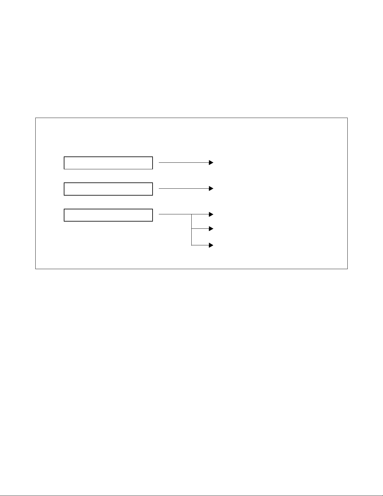
2. REFERENCE MANUAL
During installation, refer to the NEAX2000 IVS manuals listed in Figure 1-1.
REFERENCE MANUALS
MAINTENANCE MANUAL
COMMAND MANUAL
CIRCUIT CARD MANUAL
DESCRIPTION
MAINTENANCE PROCEDURE
COMMAND DESCRIPTION
CIRCUIT CARD DESCRIPTION
CIRCUIT CARD MOUNTING CONDITIONS
SWITCH SETTING OF CIRCUIT CARD
Figure 1-1 Installation Reference Manuals
NDA-24219 CHAPTER 1
Page 1
Revision 2.0
Page 16
3. HOW TO FOLLOW THIS MANUAL
The Installation Procedure is shown by means of flowcharts with an NAP (NEC Action Procedure) Number. The
detail of the work for each step is described in corresponding NAP.
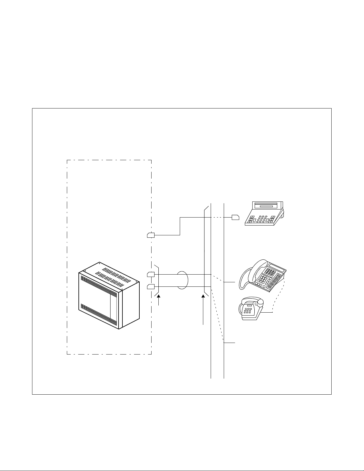
4. SCOPE OF INSTALLATION PROCEDURES
This manual covers the installation shown in Figure 1-2.
NAP-200-003:
INSTALLATION OF MAIN EQUI PMENT
NAP-200-007:
SWITCH SETTING OF CIRCUIT CARDS
NAP-200-008:
MOUNTING OF CIRCUIT CARDS
MDF
MDF CABLE
NAP-200-005:
CABLE RUNNING
TO MDF
NAP-200-006:
TERMINATION OF
CABLES ON MDF
Single Line Telephone
TO TAS INDICATOR, ALM
INDICATOR
Figure 1-2 Scope of Installation Procedures
SN610
ATTCON
or
DESKCON
Multiline Terminal
APR Adapter
CHAPTER 1 NDA-24219
Page 2
Revision 2.0
Page 17
CHAPTER 2 GENERAL INFORMATION
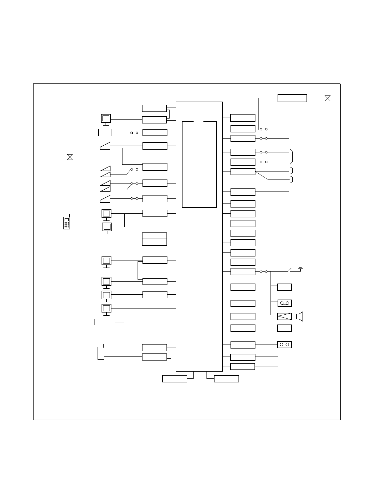
1. TRUNKING DIAGRAM
Figure 2-1 shows a typical trunking diagram for the PBX.
Single Line
Telephone
Multiline Terminal
Multiline Terminal
Wireless
PS
ISDN BRI
STATION
VOICE MA IL
SYSTEM
DESKCON
Via APR
DSS
Long Line DSS
SN610 ATTCON
SMDR
MCI
PC FOR OAI
and ACD-MIS
PC for OAI
DTE
MAT
From LC
(For Remote
Maintenance)
ZONE
TRANSCEIVER
MODEM
RS 232C
V.11
TCP/IP
V.11
RS-232C
Note 1
ICH
ILCA
LCD
PW00
DLCD/DLCJ
DLCB
DLCC
AP00
VM00
VM01
AP01
ETHER
DPC
RS 232C
PW00
CSIA
Note 2
MP
INCLUDING
SW
DTG
PBSND
16CFT
MLDT
PLO
MEM
MODEM
PBR
TNT
SMDR
RSTB-911
COT
AUC/DIT
ODT
ODT
DTI
BRT
CCH
DCH
PBR
DA T
PLO
MFR
CFT
DK
COT
COT
COT
COT/TNT
TNT
COT
COTG
PFT
6/10 PARTY CONFERENCE
8-PFT
C.O. LINE
DID LINE
2W E&M
4W E&M
ANNOUNCEMENT
MACHINE(*)
EXTERNAL HOLD TONE(*)
TIE LINE
DIGITAL LINK
ISDN (PRI)
NETWORK
ISDN (BRI)
NETWORK
KEY(*)
AMP(*)
SPEAKER(*)
(*)
EXTERNAL HOLD TONE(*)
ALL PSAP
ANALOG CALLER ID
CSH
RSTC
Note 3: An external Modem is no t required when the Built-In Modem on the MP is used.
Note 4: NEAX1000 may also be used as a Remote PIM.
Note 5: Customer provides equipment marked with (*).
Figure 2-1 PBX Trunking Diagram
NDA-24219 CHAPTER 2
Page 3
Revision 2.0
Page 18

Table 2-1 Symbols in Trunking Diagram Description
SYMBOL DESCRIPTION
AMP Amplifier for External Speaker
AP00 SMDR/MCI/PMS/Hotel Application Card KEY External Key
AP01 OAI Interface Card LCD/LCS Line Circuit Card
AUC Analog Universal Circuit Card
(Long Line Circuit, DID Trun k)
BGM External Music Source for Multiline
Terminal Back Ground Music Service
CCH Common Channel Handler Card MEM Main Memory
CFT 6/10-Party Conference Trunk Card MFR MF Receiver Trunk Card (TIANI)
COT C.O. Trunk Card MLDT Melody Trunk Card
COTG Analog Caller ID Trunk Card MODEM Modem
CSIA Zone Transceiver Line Card MP Main Processor Card
DAT Digital Announcement Trunk Card PF T Power Failure Transfer
DCH D -Channel Handler Card ODT OD Trunk Card (2/4 wire E&M)
DIT DID Trunk Card PBR PB Receiver Card
SYMBOL DESCRIPTION
ILCA BRI Station Line Card
(for Single Line Telephone)
MAT Maintenance Administration Terminal
MDF Main Distribution Frame
DK External Relay/Key Interface Card PBSND PB Sender
DLCD/DLCJ Digital Line Circuit Card
(for Multiline Terminal/DESKCON)
DLCB Digital Line Circuit Card
(for Multiline Terminal Long Line/
DESKCON)
DLCC Digital Line Circuit Card
(for SN610 ATTCON)
DPC Data Port Controller Card RSTC Register Card for Analog Caller ID
DSS DSS Console SMDR Station Message Detail Recording
DTI Digital Trunk Interface Card SW Time Division Switch
DTG Digital Tone Generator TNT Tone/Music Source Interface Card
ETHER Ethernet Control Card 16CFT 16 Circuit Three/Four Party Conference
FP Firmware Processor Card VM00 Digital VMS wit h 4-Digital Ports
ICH BRI Station Application Card VM01 4 additional Digital Ports
Note: Refer to NAP-200-008 and the Circuit Card Manual for details of circuit cards.
PLO Phase Lock Oscillator
PW00 Po wer Card for 2 Zone Transceivers or one
Attendant DeskCon
RSTB-911 Register/Sender E911
Trunk
CHAPTER 2 NDA-24219
Page 4
Revision 2.0
Page 19
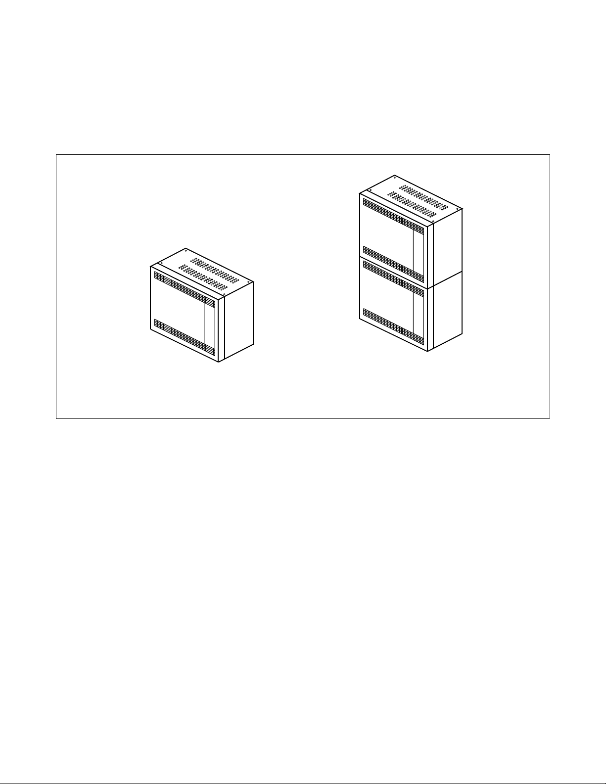
2. SYSTEM CONFIGURATIONS
2.1 PIM Configuration
The PBX system can accommodate a maximum of 48 ports per PIM. A maximum of 88 ports are available with a
two PIM configuration (PIM0 Slot LT08/AP4 used for PN-BS00).
TWO PIM CONFIGURATIONONE PIM CONF IGU RATION
Figure 2-2 PIM Configuration
NDA-24219 CHAPTER 2
Page 5
Revision 2.0
Page 20
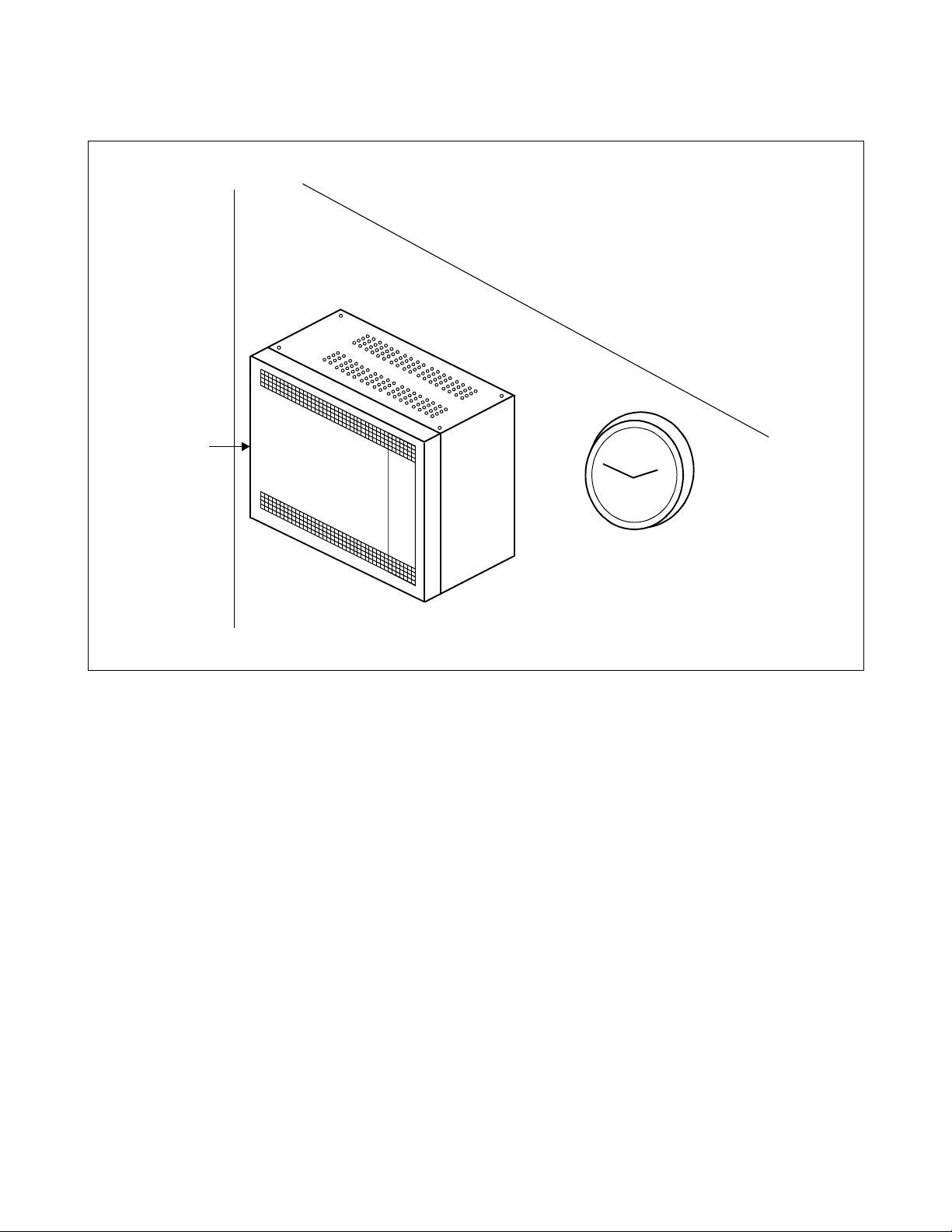
2.2 Installation Methods
PIM
Figure 2-3 Wall-Mounting Installation
CHAPTER 2 NDA-24219
Page 6
Revision 2.0
Page 21
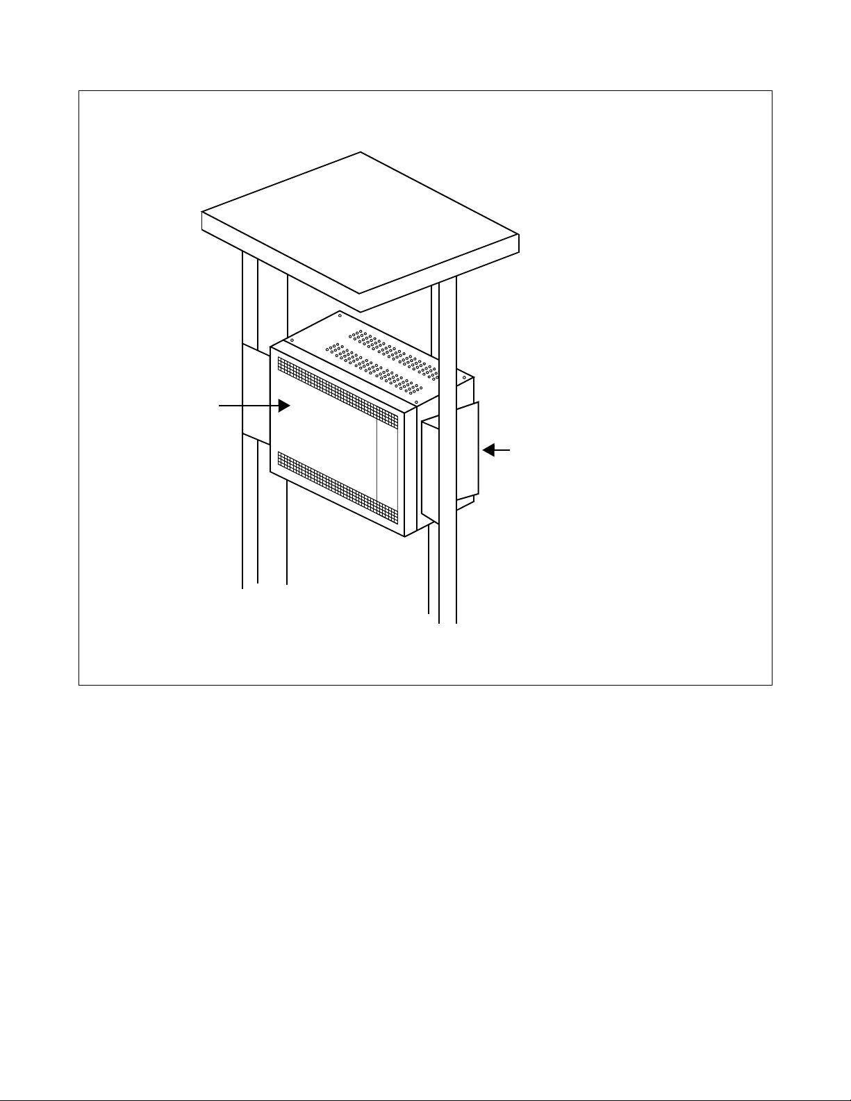
PIM
19”BRACKET (H)
Figure 2-4 19-Inch Rack-Mounting Installation
NDA-24219 CHAPTER 2
Page 7
Revision 2.0
Page 22
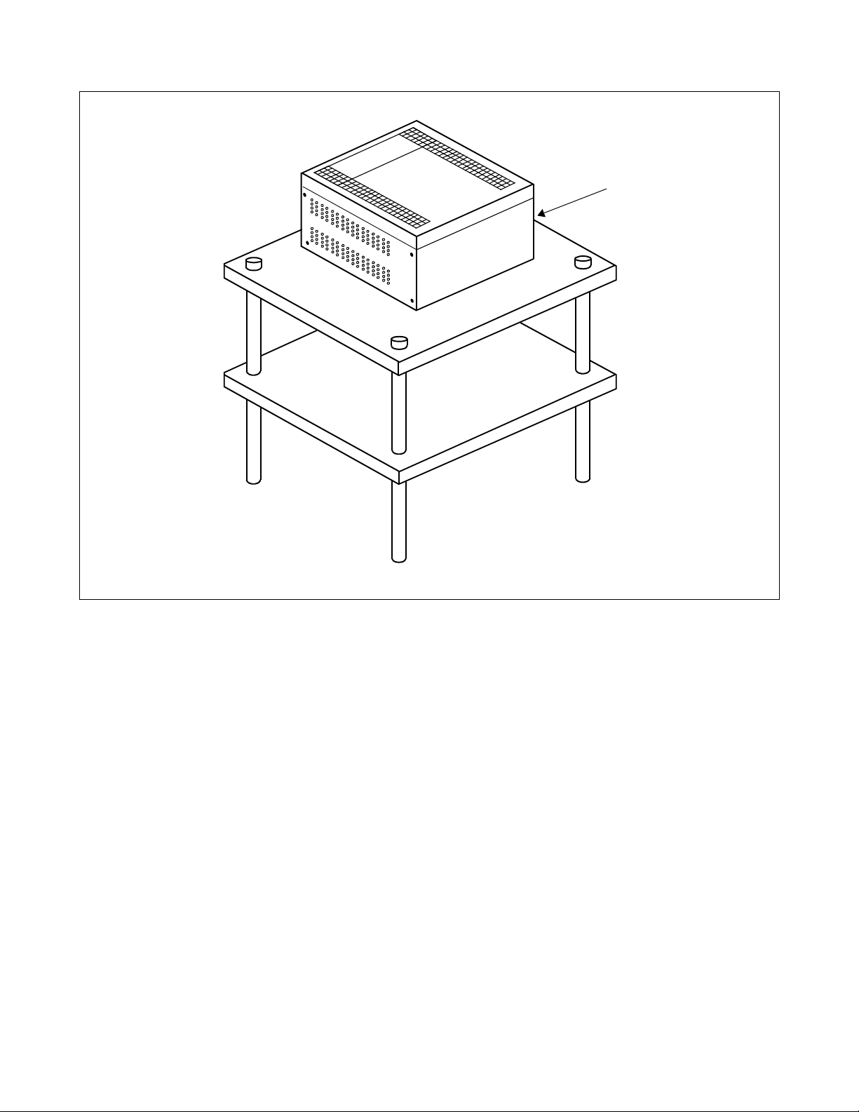
PIM
Figure 2-5 Desktop Installation
CHAPTER 2 NDA-24219
Page 8
Revision 2.0
Page 23

3. FUNCTIONAL OUTLINE OF EQUIPMENT
This section ex pla in s th e functional outline of the equipment (mod ule s, i nstallation hardware, circuit ca rd s) used in
the PBX.
3.1 Functional Outline of Modules
Table 2-2 shows the functional outline of the modules.
Table 2-2 Functional Outline of Modules
MODULES
SN1420 PIMAB-A PIM Port Interface Module (PIM)
FUNCTIONAL
NAME
FUNCTIONAL OUTLINE
A PIM provides 10 card slots for common control, Line/Trunk, and
Application Processor (AP) cards. It also houses a AC/DC Power Supply
and batteries for protection from short-term power interruption (standard).
T wo champ connectors for lin e/trunk (LTC0 to 1) and a connector for Power
(PWR) are located at the lower front side of the PIM.
A PIM provides a maximum of 9 card s l ots for line/trunk (LT) cards. At
maximum configuration, the system is comprised of 2 PIMs and it provides
88 physical ports (48 ports x 2) to MDF (PIM0 Slot LT8/AP4 used for PNBS00).
3.2 Functional Outline of Installation Hardware
Table 2-3 shows the functional outline of installation hardware.
Table 2-3 Functional Outline of Installation Hardware
INSTALLATION
HARDWARE
COVER PARTS TOP
19” BRACKET 19”
NDA-24219 CHAPTER 2
FUNCTIONAL
NAME
BOTTOM
COVER
BRACKET
FUNCTIONAL OUTLINE
Bottom Cover (includes Top Cover)
This hardware (bottom cover and top cover) is used for all NEAX1000
installations. A 4-rubber foot is required for desktop installation with PIM.
19-inch Bracket
The 19-inch bracket is sets of hardware to mount the PIM in IEC standard 19inch rack. One set of 19-inch bracket is required for PIM.
Page 9
Revision 2.0
Page 24

3.3 Functional Outline of Circuit Cards
3.3.1 Control Circuit Card
Table 2-4 shows the functional outline of each control circuit cards.
Table 2-4 Functional Outline of Control Circuit Cards
CARD NAME
PN-CP03 MP Main Processor Card
PZ-PW86 PWR Main Power Supply Card
PZ-PW112 PWR Main Power Supply Card
PN-BS00-B BS00 Bus Interface Card for PIM0
FUNCTIONAL
NAME
FUNCTIONAL OUTLINE
This card is equipped with Memory, TDSW (1024CH × 1024CH), 16-Line
CFT , DTMF Sender , Clock, PLO (recei ver mode 2 ports), R S-232C Ports (2
ports) for MAT/Built-in SMDR, modem for remote maintenance, and
Music-On-Hold tone source (Melody IC/TNT), 4-circuit PBR (for PB
calling or DID). This card is used on the basis of one per system.
Input: AC 120 V (50 Hz/60 Hz)
Output: –27 V (4.5 A), +5 V (7.5 A)
One card is mounted in PIM.
Note: This card does not provide ring generator or message wait volt-
age.
Input: AC 120 V (50 Hz/60 Hz)
Output: –27 V (3.5 A), +5 V (4.0 A)
One card is mounted in PIM.
Note: This card does not provide ring generator or message wait volt-
age.
This card is equipped with functions of driver/receiver of various signals,
functions of adjusting gate delay timing and cable delay timing, functions
of monitoring I/O Bus and PCM Bus, and functions of controlling power
supply. When the system consists of two PIMs, this card is mounted one in
PIM0
PN-BS01-B BS01 Bus Interface Card for PIM1
This card is equipped with functions of driver/receiver of various signals,
functions of adjusting gate delay timing and cable delay timing, functions
of monitoring I/O Bus and PCM Bus, and functions of controlling power
supply. When the system consists of two PIMs, this card is mounted one in
PIM1.
SPN-DAIB DAIB Firmware Processor-Bus Card—With T1
Used when installing PIM as a Remote PIM
SPN-DAIC DAIC Firmware Processor-Bus Card—With T1
Used when installing PIM as a remote PIM expanded to 43 ports.
CHAPTER 2 NDA-24219
Page 10
Revision 2.0
Page 25

3.3.2 Application Circuit Cards
Table 2-5 shows the functional outline of each application circuit card.
Table 2-5 Functional Outline of Application Circuit Cards
CARD NAME
SPN-AP00-A AP00 Application Processor Card
SPN-AP01 AP01 Application Processor Card
SPN-BRTA BRI Basic Rate (2B+D) Interface Trunk Card (S/T Interface)
SPN-ME00 EXTMEM Memory Expansion Card
SPN-CC00 ETHER Ethernet Control Card
SPN-CK00 PLO Phase Locked Oscillator Card
FUNCTIONAL
NAME
FUNCTIONAL OUTLINE
This card is equipped with four RS-232C ports, and is used for SMDR, H/M Printer,
PMS functions and MCI. This card is used on the basis of one per system.
This card is equipped with one RS-232C port and one Ethernet interface port, and is
used for OAI function. Also, this card is used to expand authorization code and ACD.
This card is used on the basis of one per system.
This card has one circuit of Basic Rate interface and provides one 2-channel PCM
digital line.
This card is used with PN-AP00-A card for providing expansion memory.
This card can be equipped with an expansions SRAM card (1MB) as SMDR data
memory.
This card is used with the PN-AP01 card to accommodate the Ethernet, transmitting/
receiving a signal of TCP/IP protocol.
This card is a phase locked oscillator for providing a synchronized clock signal with the
network.
This card is used when the PBX is a master office or when the PBX requires two clock
supply routes and those frequencies differ.
SPN-24DTA/
SPN-24DTA-A
SPN-4RSTB MFR 4-line MF Receiver Trunk card
SPN-4RSTC CIR 4-line CALLER ID Receiver Trunk Card
SPN-SC00 CCH Common Channel Handler Card
SPN-SC01 DCH D-channel Handler Card
SPN-SC02 ICH ISDN-channel Handler Card
NDA-24219 CHAPTER 2
DTI Digital Trunk Interface (23B+D, 1.5 Mbps) Card
This card accommodates 24-channel, PCM digital lines.
This card is used for MF S ignaling on Digit al DID trunks. A max imum of four cards can
be provided per one system, including the PN-4RSTC card.
This card is used for CALLER ID (CLASS SM) on analog trunks. A maximum of four
cards can be provided per one system, including the PN-4RSTB card.
This card transmits/receives signals on the common signaling channel of No. 7 CCIS.
This card transmits/receives signals on the D channel of ISDN Primary Rate (23B+D).
This card provides the D channel signaling interface and controls an ILC (Layer 2 and
3). Provides signaling interface for two ILCA cards.
Page 11
Revision 2.0
Page 26

Table 2-5 Functional Outline of Application Circuit Cards (Continued)
CARD NAME
SPN-DAIA DAIA Firmware Processor Bus Card—With T1
SPN-4RSTB-
911
SPN-SC03 CSH Channel Handler for Zone Transceivers
SPN-SC03 ICH ISDN-BRI Channel Handler
FUNCTIONAL
NAME
Used in main system when connecting to Remote PIM SPN-DAIB.
MF-911 Provides MF signaling for Enhanced 911.
Provides D-channel signaling interface for four ILCA cards.
FUNCTIONAL OUTLINE
3.3.3 Line/Trunk Circuit Cards
Table 2-6 shows the functional outline of each line/trunk circuit card.
Table 2-6 Functional Outline of Line/Trunk Circuit Cards
CARD NAME
PN-2AMPA AMP 2-line Amplifier Trunk Card
FUNCTIONAL
NAME
FUNCTIONAL OUTLINE
This card equipped with the functions of Echo Canceller (EC), Automatic Gain
Controller (AGC) and Tone Disabler (TD).
PN-AUCA AUC 2-line Long-Line Circuit Card provided with the Power Failure Transfer (PFT) function
line resistance in the case of a long-line circuit: Max. 2500 ohms (incl us ive of the
internal resistance of the distant office equipment)
This card is internally equipped with a –48 V DC On-Bo a rd Power Supply.
This card can also be used as a 2-line Direct Inward Dialing trunk card.
PN-CFTA CFT Conference Trunk Card
Use of one card:Can control a conference of up to six participants.
Use of two cards:Can control a conference of up to ten participants.
PN-4COTB COT 4-line Central Office Trunk Card (ground-start/loop-start trunk) equipped with the
functions for loop detection, sending/d etecting ground on Ring/Tip wire
PN-4COTG COT 4-line Central Off ice T runk C ard (loop-start trunk) equi pped with the funct ions for loop
detection, receiving/sending the Caller ID (CLASS SM) signal
PN-8COTM COT 8-line Central Office Trunk Card (loop-start trunk only)
No loop disconnect detection is provided.
PN-8COTP COT 8-line Central Office Trunk Card (loop-start trunk only)
loop disconnect detection is provided.
PN-2CSIA CSIA 2-Line Zone Transceiver Card
PN-2DATA DAT 2-line Digital Announcement Trunk Card
Duration: Max. 60 seconds.
CHAPTER 2 NDA-24219
Page 12
Revision 2.0
Page 27

Table 2-6 Functional Outline of Line/Trunk Circuit Cards (Continued)
CARD NAME
PN-4DITB DIT 4-line Direct In-Dialing Trunk Card
PN-DK00 DK Circuit card for External Relay Control/External Key Scan
PN-4DLCA/
PN-4DLCM
PN-2DLCB/
PN-2DLCN
PN-2DLCC DLC 2-line Digital Line Circuit Card for Multiline Terminal Series II/SN610 Attendant
FUNCTIONAL
NAME
This card is equipped with the function for loop detection, sending reverse signal and
PB to DP signal conversion. This card is internally equipped with –48 V DC On-Board
Power supply.
This card is provided with eight circuits, and can provide the abov e-men tioned co ntrol
functions on a per circuit basis.
DLC 4-line Digital Line Circuit card for Multiline Terminal Series E/Elite/Series III/
ElectraPro/DSS Console (–27 V Version, 2-wire type) Note
This card is equipped with quick diagn ostics to detect short line conditions and the
normality (Synchronous/Asynchronous) of the terminal.
DLC 2-line Digital Line Circuit Card for Multiline T erminal Series E/Series III/DSS Console/
DESKCON (–48V Version, 2-wire type) Note
This card is equipped with quick diagn ostics to detect short line conditions and
normality (Synchronous/Asynchronous) of terminal. This card is internally equipped
with a –48 V DC On-Board Power Supply.
Console (–48 V Version, 4-wire type) Note
This card is equipped with quick diagn ostics to detect short line conditions and the
normality (Synchronous/Asynchronous) of the terminal. This card is internally
equipped with –48 V On-Board Power Supply.
FUNCTIONAL OUTLINE
PN-4DLCD/
PN-4DLCQ
PN-4DLCF DLC 4-line Digital Line Circuit Card for Multiline Terminal Series II/SN610 Attendant
PN-8DLCJ/
PN-8DLCP
PN-2DPCB DPC 2-line Data Port Controller Card
PN-2ILCA ILC 2-line ISDN Line Circuit Card
PN-4LCD-A LC 4-line Analog Line Circuit Card for single line telephones
DLC 4-line Digital Line Circuit Card exclusively used for Multiline T erminal Series E/Series
III/DSS Console/DESKCON (–27 V Version, 2-wire type) Note
This card is equipped with quick diagn ostics to detect short line conditions and the
normality (Synchronous/Asynchronous) of the terminal.
Console (–27 V Version, 4-wire type) Note
This card is equipped with quick diagn ostics to detect short line conditions.
DLC 8-line Digital Line Circuit Card for Multiline T erminal Series E/Series III/DSS Console/
DESKCON (–27 V Version, 2-wire type) Note
This card is used for the intra-office or inter-office digital data transmission on fixed
path connection. This card can acc ommodate a maximum o f two DTE with V.11 (X.21)
interface or V.24/V.28 (RS-232C) interface.
This card provides a physical interface to ISDN Terminals.
Loop resistance: Max. 600 ohms
This card is equipped with the function for control ling Message Waiting Lamp.
Each 4 circuits are equipped with momentary open function.
This card is equipped with quick diagn ostics to detect short and open line conditions.
This card is internally equipped with a +80 V DC-DC Power Supply circuit.
NDA-24219 CHAPTER 2
Page 13
Revision 2.0
Page 28

Table 2-6 Functional Outline of Line/Trunk Circuit Cards (Continued)
CARD NAME
PN-8LCS LC 8-line Analog Line Circuit Card for single-line telephones
PN-M03 M03 V.35 DTE Interface Card
PN-2ODTA ODT 2-line OD Trunk Card
PN-PW00 PWR Provides -48V power f or one DeskCon or two zone tran sceivers; maximum is 3 per
PN-8RSTA PBR 8-line DTMF Receiver Card
PN-TNTA TNT 2-line Tone/Music Source interface Card
PZ-VM00 4VM 4-Port Voice Mail Card (NEAX Mail AD-8)
PZ-VM01 4VMEXT 4-Port Expansion Card for AD-8 (VM00)
FUNCTIONAL
NAME
FUNCTIONAL OUTLINE
Loop resistance: Max. 600 Ω
This card is equipped with a controller for momentary open function.
This card is used together with the PN-2DPCB card to provide the V.35 interface.
This card can be used as either a 2-wire E&M trunk or a 4-wire E&M trunk, and is
internally equipped with a –48 V DC On-Board P ower Supply.
Both No. 0 and No. 1 circuits mu st be set to same purp ose (2-wire or 4-wire) in one card.
system; uses two card slots
This card can be used for a DTMF station line, DID or tie line.
This card is used for BGM or Music on Hold, and is equ ipped with tw o interface for an
external tone/music source.
Note: The cable length between the DLC and terminal varies depending on the type of terminal. For the line conditions
each terminal, refer to
TERMINAL TYPE CARD TYPE
DTP-8-1 PN-8DLCJ / 8DLCP
DTP-8D-1 PN-8DLCJ / 8DLCP
Table 2-7
Table 2-7 Line Condition of Each Terminals
(STANDARD)
PN-4DLCD / 4DLCQ
(STANDARD)
PN-2DLCB / 2DLCN
(LONG)
(STANDARD)
PN-4DLCD / 4DLCQ
(STANDARD)
PN-2DLCB / 2DLCN
(LONG)
.
CABLE LENGTH
(Cable 24AWG)
984ft. (300m) Note 1
984ft. (300m)
[3937ft. (1200m)]
2788ft. (850m)
[3937ft. (1200m)]
984ft. (300m) Note 1
984ft. (300m)
[3937ft. (1200m)]
2788ft. (850m)
[3937ft. (1200m)]
REMARKS
CHAPTER 2 NDA-24219
Page 14
Revision 2.0
Page 29

Table 2-7 Line Condition of Each Terminals (Continued)
TERMINAL TYPE CARD TYPE
DTP-16-1 PN-8DLCJ / 8DLCP
(STANDARD)
PN-4DLCD / 4DLCQ
(STANDARD)
PN-2DLCB / 2DLCN
(LONG)
DTP-16D-1 PN-8DLCJ / 8DLCP
(STANDARD)
PN-4DLCD / 4DLCQ
(STANDARD)
PN-2DLCB / 2DLCN
(LONG)
DTP-32-1 PN-8DLCJ / 8DLCP
(STANDARD)
PN-4DLCD / 4DLCQ
(STANDARD)
PN-2DLCB / 2DLCN
(LONG)
DTP-32D-1 PN-8DLCJ / 8DLCP
(STANDARD)
PN-4DLCD / 4DLCQ
(STANDARD)
PN-2DLCB / 2DLCN
(LONG)
DSS/BLF Console
Note 2
ETJ-8-1 PN-8DLCJ / 8DLCP
ETJ-16DC-1 PN-8DLCJ / 8DLCP
PN-8DLCJ / 8DLCP
(STANDARD)
PN-4DLCD / 4DLCQ
(STANDARD)
PN-2DLCB / 2DLCN
(LONG)
(STANDARD)
PN-4DLCD / 4DLCQ
(STANDARD)
PN-2DLCB / 2DLCN
(LONG)
(STANDARD)
PN-4DLCD / 4DLCQ
(STANDARD)
PN-2DLCB / 2DLCN
(LONG)
CABLE LENGTH
(Cable 24AWG)
656ft. (200m) Note 1
656ft. (200m)
[3937ft. (1200m)]
2788ft. (850m)
[3937ft. (1200m)]
656ft. (200m) Note 1
656ft. (200m)
[3937ft. (1200m)]
2788ft. (850m)
[3937ft. (1200m)]
656ft. (200m) Note 1
656ft. (200m)
[3937ft. (1200m)]
2788ft. (850m)
[3937ft. (1200m)]
656ft. (200m) Note 1
656ft. (200m)
[3937ft. (1200m)]
2788ft. (850m)
[3937ft. (1200m)]
984ft. (300m) Note 1
984ft. (300m)
2788ft. (850m)
984ft. (300m) Note 1
984ft. (300m)
[3937ft. (1200m)]
2788ft. (850m)
[3937ft. (1200m)]
656ft. (200m) Note 1
656ft. (200m)
[3937ft. (1200m)]
2788ft. (850m)
[3937ft. (1200m)]
REMARKS
NDA-24219 CHAPTER 2
Page 15
Revision 2.0
Page 30

Table 2-7 Line Condition of Each Terminals (Continued)
TERMINAL TYPE CARD TYPE
ETJ-16DD-1 PN-8DLCJ / 8DLCP
(STANDARD)
PN-4DLCD / 4DLCQ
(STANDARD)
PN-2DLCB
(LONG)
ETJ-24DS-1 PN-8DLCJ / 8DLCP
(STANDARD)
PN-4DLCD / 4DLCQ
(STANDARD)
PN-2DLCB
(LONG)
SN610 ATTCON PN-2DLCC
(LONG)
PN-4DLCF
(STANDARD)
DESKCON PN-4DLCD / 4DLCQ and
PW00 or AC Adapter
PN-8DLCJ / 8DLCP and
PW00 or AC Adapter
CABLE LENGTH
(Cable 24AWG)
656ft. (200m)
656ft. (200m)
[3937ft. (1200m)]
2788ft. (850m)
[3937ft. (1200m)]
492ft. (150m)
492ft. (150m)
[3937ft. (1200m)]
2788ft. (850m)
[3937ft. (1200m)]
3937ft. (1200m)
984ft. (300m)
1500ft. (457m)
1000ft. (304m)
REMARKS
Note 1
Note 1
Note 3
* The value in the [ ] shows the cable length when using the long line function.
Note 1: When using PN-8DLCJ or PN-8DLCP card, it is not available long line function.
Note 2: The DSS/BLF Console requires local AC/DC power supply.
Note 3: With AC/DC power at DESKCON 3000’ with 4DLCD
CHAPTER 2 NDA-24219
Page 16
Revision 2.0
Page 31

4. CIRCUIT CARD INSTALLATION CONDITIONS
4.1 Circuit Card Mounting Slots
Figure 2-6 shows circuit card mounting slots allocated in the PIM, on the basis of circuit card type.
Number of Ports Available per Slot
4-Port Card Mounted
8-Port Card Mounted
AD-8
uses
vacant
space
when
mounted
Slot 00
PWR0C
vacant
space
444444444
888880
00LT01LT02LT03LT04
LTC1
LTC0
(10 min. Internal Battery Back-Up Standard)
LT
/
AP0
1
05
LT
/
AP1
8018
06
07
LT
LT
/
AP2
AP3
/
08
LT
/
AP4
PWR0B
09
MP
/
BUS
P
W
R
LT01 - LT08 : Line/trunk circuit card mounting slots
• LT00 : No connection to MDF. When NEAXmail AD8 is mounted here, internal modem leads for AD8 are brought out on pins 25 & 50 of LTC1
cable for connection to single-line station or C.O. trunk.
• LT01 - LT04, LT06, LT08 : All line/trunk circuit cards can be mounted.
• LT05, LT07 : 4-port circuit cards that require cabling may be mounted only when 8port cards are not mounted in the slot to the left of them.
AP0 - AP5 : Application circuit card mounting slots
MP : PN-CP03 mounting slot
BUS : PN-BS00-B (Slot 08 on PIM0), PN-BS01-B (Slot 09 on PIM1) mounting slot
PWR : PZ-PW86/PW112 mounting slot
PWR0B : Connector for termination of ring generator when single-line card(s) are mounted. System
power supply does not supply ringing voltage
2
PWR0C : Connector for termination of PW91 Power for Zone Transceivers
1
When an 8-port card is mounted in Slot 04/06, Slot 05/07 can only be mounted with the following cards:
SPN-AP00 SPN-AP01 SPN-ME00 SPN-SC01
SPN-SC02 SPN-4RSTB SPN-4RSTB-911 SPN-4RSTC
SPN-CK00 SPN-CC00 PN-M03 SPN-SC03 (CSH)/(ICH)
2
It is re commended t hat an APR ad apter, which has a b uilt -in r ing g ener ator, be used in dual-por t mode t o
provide interface for single-line devices. APRs provide hookflash and disconnect signaling when 1800
series software or higher is used.
Figure 2-6 Circuit Card Mounting Slots
NDA-24219 CHAPTER 2
Page 17
Revision 2.0
Page 32

4.2 Installation Conditions
(20) The application circuit cards PN-BRTA and PN-24DTA-A cannot be mounted in slots AP1 or AP3 when
an 8-port card is mounted in Slot 04 or 06, since these slots share a connection to the MDF via the backplane.
(21) The application circuit ca rd t ype PN-CC00 can be mounted in any LT/AP slot, but it occupies two s lot po-
sitions; i.e. the slot immediately to its right must be vacant.
(22) PN-PW00 can be mounted in any LT/AP slot or LT slot, but it occupies tw o slots; i.e., the sl ot immediatel y
to its left must be vacant.
(23) AD8 (PN-VM00) can be mounted in any LT or LT/AP slot, but it occupies three slots; i.e., the two slots
immediately to its le ft must be vac ant. It i s recommended that LT00 be used when mounting the AD8 since
the vacant spac e to its left is specifically provided for this pu rpose and o nly LT00 brings lead s out for termination of the AD8 internal modem.
Note: The PN-CC00 must be mounted adjacent to its related PN-AP01 card, in order to allow the connection of cable type
48-TW-0.3 CONN CA between these cards.
CHAPTER 2 NDA-24219
Page 18
Revision 2.0
Page 33

CHAPTER 3 INSTALLATION PROCEDURE
1. PRECAUTIONS
1.1 Grounding Requirements
The system grounding must have a specific ground resistance and AC noise level, and is to be connected to a predetermined terminal in the PBX. Standard grounding requirements are as follows:
• Communication grounding: Less than 10 ohm
• Protective ground for PIM: Less than 10 ohm
Note: The AC ripple on these various grounds should be less than 0.5 Vp-p.
CAUTION:
Grounding circuit continuity is vital for safe operation of telecommunication equipment. Never
operate this equipment with the grounding conductor disconnected.
NDA-24219 CHAPTER 3
Page 19
Revision 2.0
Page 34

1.2 Static Electricity Guard
The installer must wear a grounded wrist strap to protect circuit cards from static electricity.
WHEN PLUGGING/UNPLUGGING A CIRCUIT CARD
•
PBX
FRAME GROUND SCREW
WRIST STRAP
CONNECT THE GROUND WIRE TO THE
FRAME EARTH OF THE EQUIPM ENT
.
• WHEN HOLDING A CIRCUIT CARD
NEVER TOUCH THE COMPONENTS
OR SOLDERED SURFACE WITH
BARE HANDS.
CARD FRONT
Figure 3-1 Static Electricity Guard
CHAPTER 3 NDA-24219
Page 20
Revision 2.0
Page 35

• WHEN MAKING A SWITCH SETTING ON A CIRCUIT CARD
CIRCUIT
CARD
• WHEN CARRYING A CIRCUIT CARD
CIRCUIT
CARD
Figure 3-1 Static Electricity Guard (Continued)
WEAR A WRIST STRAP AND PERFO RM
THE WORK ON A GROUNDED
CONDUCTIVE WORK SURFACE.
CONDUCTIVE
POLYETHYLENE
BAG
WHEN CARRYING A CIRCUIT
CARD AROUND, KEEP THE
CARD IN A CONDUCTIVE
POLYETHYLENE BAG.
NDA-24219 CHAPTER 3
Page 21
Revision 2.0
Page 36

1.3 Removing/Inserting Circui t Cards
When removing a circuit card from the PIM or when inserting a circuit card in the PIM, follow the procedure in
Table 3-1.
Table 3-1 Removing/Inserting Circuit Cards Procedure
PROCEDURE
CIRCUIT CARD
INSERT REMOVE
CONDITION
•PN-CP03 (MP)
• PZ-PW86 (PWR)
• PZ-PW112 (PWR)
•PN-PW00
• PN-AP00 (AP00)
• PN-ME00 (EXTMEM)
•PN-BRTA (BRT)
• PN-BS00-B (BS00)
• PN-BS01-B (BS01)
• PN-CK00 (PLO)
• PN-24DTA- A (DTI)
• PN-4RSTB (MFR)
•PN-4RSTC (CIR)
•PN-SC00 (CCH)
•PN-SC01 (DCH)
•PN-SC02 (ICH)
•PN-SC03 (ICH)
•PN-SC03 (CSH)
• PN-VM00
• PN-AP01 (AP01)
• PN-CC00 (ETHER)
Power off
↓
Insert
↓
Power on
Power off or
MB switch on
↓
Insert
↓
Power on or
MB switch off
Refer to the OAI System Manual.
Power off
Remove
Power on
Power off or
MB switch on
Remove
Power on
Always insert or remove these circuit cards
↓
↓
↓
↓
with power off to prevent damage to the card
or other system circuitry.
Always insert or remove these circuit cards
under Make Busy condition or power off to
prevent damage to the card or other system
circuitry.
CHAPTER 3 NDA-24219
Page 22
Revision 2.0
Page 37

CAUTION:
Always hold the card name label ar ea wh en inserting or r emoving a cir cuit c ard. Touching another area may result in exposure to hazard voltages.
PBX
NEVER TOUCH THE COMPONENTS OR
SOLDERED SURFACE WITH BARE
HANDS.
CARD FRONT
NDA-24219 CHAPTER 3
Page 23
Revision 2.0
Page 38

2.PROCEDURE
This section explains the procedur es for inst alli ng the PBX sys tem. The i nstal ler should follow the f lowchart proce dure shown in Figure 3-2. In the flowchart, an NAP (NEC Action Procedure) Number, denoted on the right side of
each action, refers to the details for each procedure.
START
UNPACKING
MARKING AND DRILLING
INSTALLATION OF
MAIN EQUIPMENT
PWR CA-A AND
BUS CABLE CONNECTION
CONNECTION OF
BATTERY
CABLE RUNNING
TO MDF
TERMINATION OF
CABLES ON MDF
NAP- 200-001
NAP- 200-002
NAP- 200-003
NAP- 200-004
NAP- 200-005
NAP- 200-006
NAP- 200-007
SWITCH SETTING OF
CIRCUIT CARDS
A
NAP- 200-008
Figure 3-2 Procedure Flowchart
CHAPTER 3 NDA-24219
Page 24
Revision 2.0
Page 39

A
MOUNTING OF
CIRCUIT CARDS
SYSTEM INITIALIZATION
SYSTEM DATA ENTRY
MOUNTING OF FRONT COVER
AND
OPERATION
TEST
CLEANING AND
VISUAL CHECK
END
NAP- 200-009
NAP- 200-010
NAP- 200-011
NAP- 200-012
NAP- 200-013
Figure 3-2 Procedure Flowchart (Continued)
The label, shown in Figure 3-3, is attached to the NAP sheet for each procedure in which circuit cards are handled.
When doing such a procedure, the installer must perform the procedure with caution, to prevent damage caused by
static electricity (See Section 1.2 Static Electricity Guard in this chapter).
ATTENTION
Contents
Static Sensitive
Handling
Precautions Required
Figure 3-3 Static-Sensitive Caution Label
NDA-24219 CHAPTER 3
Page 25
Revision 2.0
Page 40

NAP-200-001
Sheet 1/2
Unpacking
ATTENTION
Contents
Static Sensitive
Handling
Precautions Required
1. UNPACKING PROCEDURE
(1) Check the received quantity of packages containing the PBX system with the descript ion on the shipping
document.
(2) Check the packaging for external damage done by transportation and record it as necessary.
(3) Unpack the packaging (see Figure 001-1).
• For unpacking the packages containing circuit cards, a grounded wrist strap should be worn.
(4) Check the quantity of equipment and materials unpacked with the shipping document.
(5) Perform visual inspection, checking for the following items:
• Modules Overall distortion
Scratches and dents on the surface
Scratches and cracks on PIM Backplane
Broken or bent pins on PIM Backplane
• Covers Scratches and dents
• Circuit Cards Overall distortion
Scratches and cracks
Loss or damage of parts on circuit cards
• Attendant Console Scratches and cracks on the keyboard
Overall distortion
Damage to keys and lamps
CHAPTER 3 NDA-24219
Page 26
Revision 2.0
Page 41

NAP-200-001
Sheet 2/2
Unpacking
ACCESSORIES
PIM
Figure 001-1 Unpacking Main Equipment
NDA-24219 CHAPTER 3
Page 27
Revision 2.0
Page 42

NAP-200-002
Sheet 1/2
Marking and Drilling
1. CONFIRMING EQUIPMENT LAYOUT
Install the equipment in an area that provides adequate ventilation and is easily accessible to service personnel.
2. MARKING
Locate and mark the wall mounting points as shown in Figure 002-1.
30 mm (1.2 inch)
302 mm
(11.9 inch)
30 mm (1.2 inch)
209 mm
(11.6 inch)
30 mm (1.2 inch)
302 mm
290 mm
(11.6 inch)
PIM
350 mm
(13.8 inch)
ONE PIM CONFIGURATION TWO PIM CONFIGURATION
ANCHOR (x4)
354 mm
(13.9 inch)
PBX BOTTOM POSITION
(11.9 inch)
30 mm (1.2 inch)
30 mm (1.2 inch)
302 mm
(11.9 inch)
30 mm (1.2 inch)
PIM
PIM
350 mm
(13.8 inch)
ANCHOR (x4)
ANCHOR (x4)
Figure 002-1 Wall Mounting Points
354 mm
(13.9 inch)
354 mm
(13.9 inch)
CHAPTER 3 NDA-24219
Page 28
Revision 2.0
Page 43

NAP-200-002
Sheet 2/2
Marking and Drilling
3. DRILLING
Install anchor bolts as shown in Figu re 002- 2.
(1) DRILL A HOLE IN THE CONCRETE WITH A
DRILL SUITABLE FOR A PLUG BOLT A LITTLE
DEEPER THAN THE PLUG BOLT LENGTH.
(2) INSERT THE ANCHOR BOLT INTO THE HOLE.
(3) PUSH ANCHOR BOLT UNTIL THE BOLT
STAYS PERMANENTLY IN PLACE.
(4) TURN BOLT COUNTERCLOCKWISE AND
REMOVE.
Figure 002-2 Installing Anchor Bolt
(1) (2) (3) (4)
NDA-24219 CHAPTER 3
Page 29
Revision 2.0
Page 44

NAP-200-003
Sheet 1/12
Installation of Main Equipment
1. WALL-MOUNTING INSTALLATION
(1) When the system is two PIM configuration, connect PIMs with three bolts provided.
Figure 003-1 Connection of PIMs
CHAPTER 3 NDA-24219
Page 30
Revision 2.0
Page 45

NAP-200-003
Sheet 2/12
Installation of Main Equipment
(2)Using appropriate fa st ene rs ( loc al l y pr ovided; s ee Ta ble 003-1) for the type of wall construct ions, se cur e
the PIM to the wall. For the wall mounting points, refer to Figure 002-1 in NAP-200-002.
Table 003-1 Recommended Fasteners
WALL TYPE RECOMMENDED FASTENER
Plaster Board
[Thickness Min. 9.6 mm
(0.38 inch)]
Wood Wood Type Screws
Concrete Anchor Bolt Type
Note: The wall types are listed in recommendatio n order. Concrete is the most secure. Plaster b oard is the least secure.
Molly Anchor Type
Min. 3.5 mm (0.14 inch) DIA
Max. 4.5 mm (0.17 inch) DIA
Min. 3.5 mm (0.14 inch) DIA
Max. 4.5 mm (0.17 inch) DIA
Recommended 4 mm (0.16 inch) by 25 mm (0.98 inch)
NDA-24219 CHAPTER 3
Page 31
Revision 2.0
Page 46

NAP-200-003
Sheet 3/12
Installation of Main Equipment
(3) After hanging PIM onto the wall, tighten each M4 machine screw using a phillips screw driver.
M4 MACHINE SCREW-B (X4)
Figure 003-2 Screwing PIM to Wall
PIM
CHAPTER 3 NDA-24219
Page 32
Revision 2.0
Page 47

NAP-200-003
Sheet 4/12
Installation of Main Equipment
(4) Connect the TOP COVER to the upper PIM with four screws, and connect the BOTTOM COVER to the
lower PIM with four screws.
TOP COVER
BOTTOM COVER
Figure 003-3 Connecting Covers
NDA-24219 CHAPTER 3
Page 33
Revision 2.0
Page 48

NAP-200-003
Sheet 5/12
Installation of Main Equipment
(5) Connect the AC CORD-A-U to the AC INPUT connector on the PZ-PW86/PZ-PW112, and its FG cord
to the FG terminal on the chassis.
After connection of AC CORD-A-U to the A C INPUT connector, let the cord out of the PIM through the
cable hole provided wit h bottom of the PIM.
FG TERMINAL
PZ-PW86/
PZ-PW112
AC INPUT
CABLE HOLE FOR
AC CORD-A-U
H5 (PROVIDED)FG CORD
FG CORD
Figure 003-4 Conn ecting AC CORD to PIM
AC CORD-A-U
CHAPTER 3 NDA-24219
Page 34
Revision 2.0
Page 49

NAP-200-003
Sheet 6/12
Installation of Main Equipment
2.19-INCH RACK-MOUNTING INSTALLATION
(1)When the system is two PIM configuration, connect PIMs with three bolts as shown in Figure 003-1.
(2)Before mounting the PIM, con nect the TOP COVER, BOTTOM COVER and AC CORD-A-U t o the PIM
as shown in Figure 003-3 and Figure 003-4.
(3)Secure the 19” BRACKET (H) to the 19-inch Rack as shown in Figure 003-5
(4)Mount the PIM on the 19” BRACKET (H) as shown in Figure 003-5 .
B
Then, secure the PIM to the 19” BRACKET (H) as shown in Figure 003-5 .
19-INCH RACK (IEC)
19” BRACKET(H)
PIM
BOTTOM COVER
B
19” BRACKET(H)
A
C
A
C
PIM
FRONT
Figure 003-5 Mounting PIM to 19-Inch Rack
NDA-24219 CHAPTER 3
Page 35
Revision 2.0
Page 50

NAP-200-003
Sheet 7/12
Installation of Main Equipment
3.DESKTOP INSTALLATION
(1)When the system is two PIM configuration, connect PIMs with three bolts as shown in Figure 003-1.
(2)Connect the TOP COVER, BOTTOM COVER and AC CORD-A-U to the PIM as shown in Figure 003-
3 and Figure 003-4.
(3)Screw the RUBBER FOOT to the PIM as shown in Figure 003-6.
PIM
BOTTOM
RUBBER FOOT
Figure 003-6 Connecting Rubber Foot to PIM
CHAPTER 3 NDA-24219
Page 36
Revision 2.0
Page 51

NAP-200-003
Sheet 8/12
Installation of Main Equipment
4. AC POWER CABLING
(1)The cable connections on the PZ-PW86/PW112 card are shown in Figure 003-7.
• PZ-PW86(C)
BATTERY MODE SWITCH
1:NO CONNECTION
2:ON-SEAL/FLOAT2
OFF-OPEN/FLOAT1
TO AUXILIARY
EQUIPMENT
TO PWR1
CONNECTOR
PWR CNT CA-A/
PWR CNT CA-C
TO OTHER
PZ-PW86
PWR CA-A
TO BATTERY OR
OTHER PZ-PW86
BATTERY CABLE/PWR CA-A
WHITE
BLACK
PZ-PW86(C)
MJ
MN
ON
ON
1
2
GND
FG
-27V
Note 1
Note 2
ON
OFF
100/120V
–
O
240V
Note 1:Follow the Label on the front plate of the PZ-PW86.
Note 2:If GND (Signal GND) has to be separated from FG
(Frame GND), remove the link between GND and
FG terminals.
POWER OUTPUT
CABLE (+5V, -27V,E)
TO PWR0A CONNECTOR
BATTERY CONNECTOR (BATT2)
BATTERY CONNECTOR (BATT1)
CAUTION:
Set the appropriate voltage before
turning on the SW switch.
TO
GREEN
AC CORD-A
TO AC MAINS INPUT
FRAME GROUND TERMINAL ON THE CHASSIS
Figure 003-7 Cable Connection on PZ-PW86/PW112
NDA-24219 CHAPTER 3
Page 37
Revision 2.0
Page 52

NAP-200-003
Sheet 9/12
Installation of Main Equipment
PZ-PW86(D)
•
CAUTION:
BATTERY MODE SWITCH
1: NO CONNECTION
2: ON-SEAL/FLOAT 2
OFF-OPEN/FLOAT 1
TO AUXILIARY
EQUIPMENT
TO PWR1
CONNECTOR
PWR CNT CA-A/
PWR CNT CA-C
Set the appropriate voltage befor e turning on the
SW switch.
WHITE
BLACK
MJ
MN
ON
ON
1
2
100/120V
240V
PZ-PW86(D)
Note 1
Note 2
GND
FG
–27V
ON
OFF
Note 1: Fol low the Label on F ront Plate of
Note 2: If GND (Signal GND) has to be
POWER OUTPU T
CABLE (+5V , –27V,E)
–
O
PZ-PW86(D).
separated from FG (Frame GND),
remove the link between GND and
FG terminal
TO PWR0A CONNECTOR
TO OTHER PZ-PW86
PWR CA-A
BATTERY CONNECTOR (BATT2)
TO BATTERY OR
OTHER PZ-PW86
BATTERY CABLE/PWR CA-A
BATTERY CONNECTOR (BATT1)
GREEN
AC CORD-A
TO
TO AC MAINS INPUT
FRAME GROUND
TERMINAL ON THE
CHASSIS
Figure 003-7 Cable Connection on PZ-PW86/PW112 (Continued)
CHAPTER 3 NDA-24219
Page 38
Revision 2.0
Page 53

NAP-200-003
Sheet 10/12
Installation of Main Equipment
• PZ-PW112
PZ-PW112
POWER OUTPU T
CABLE (+5V, –27V,E)
TO AUXILIARY
EQUIPMENT
TO PWR1
CONNECTOR
PWR CNT CA-A/
PWR CNT CA-C
WHITE
BLACK
–
O
MJ
MN
ON
GND
FG
–27V
ON
OFF
Note
TO PWR0A CONNECTOR
Note: If GND (Signal GND) has to be
separated from FG (Frame GND),
remove the link between GND and
FG terminal
TO OTHER PZ-PW112
PWR CA-A
BATTERY CONNECTOR (BATT2)
TO BATTERY OR
OTHER PZ-PW112
BATTERY CABLE/PWR CA-A
BATTERY CONNECTOR (BATT1)
TO
GREEN
AC CORD-A
TO AC MAINS INPUT
FRAME GROUND
TERMINAL ON THE
CHASSIS
Figure 003-7 Cable Connection on PZ-PW86/PW112 (Continued)
NDA-24219 CHAPTER 3
Page 39
Revision 2.0
Page 54

NAP-200-003
Sheet 11/12
Installation of Main Equipment
(2)When the system is two PI M configuration, unplug the PWR CNT CA-A and connect the PWR CNT CA-
C as shown in Figure 003-8.
PIM1
PZ-PW86/
PZ-PW112
BWB (Back Wiring Board)
PWR1
PWR0C
SIG
(CN103)
CARD SLOT AREA
PWR0A
PIM0
PWR0C
LTC CONNECTOR AREA
BWB (Back Wiring Board)
CARD SLOT AREA
LTC CONNECTOR AREA
PWR0B
PWR CNT CA-C
PWR1
PWR0A
PWR0B
PWR CNT CA-C
PZ-PW86/
PZ-PW112
SIG
(CN103)
Figure 003-8 PWR CNT CA-C Cable Connection between PIMs
CHAPTER 3 NDA-24219
Page 40
Revision 2.0
Page 55

NAP-200-003
Sheet 12/12
Installation of Main Equipment
(3) Bring the AC CORD-A-U out of the PIM through the ca ble hole on the bot tom of the lo wer PIM, and pl ug
it into a commercial AC outlet.
TO FG
TERMINAL
AC CORD-A-U
Figure 003-9 AC Power Cable Wiring
NDA-24219 CHAPTER 3
Page 41
Revision 2.0
Page 56

NAP-200-004
Sheet 1/2
PWR CA-A and BUS Cable Connection
(1)When the system is two PIM configuration, connect the PZ-PW86/PZ-PW112 Cards to each other using
PWR CA-A cables, as shown in Figure 004-1.
•
When using internal batteries • When using external batteries
PIM1
PIM0
Note:
PZ-PW86/
PZ-PW112
PIM1
BATT2
TO BATTERY
PWR CA-A
TO BATTERY
BATT1
PZ-PW86/
PZ-PW112
PIM0
BATT2
BATT1
For details of battery connection, see NAP- 200-004.
PWR CA-A
PZ-PW86/
PZ-PW112
BATT2
BATT1
PZ-PW86/
PZ-PW112
BATT2
BATT1
TO BATTERY
Figure 004-1 Connection of PWR CA-A Cables
CHAPTER 3 NDA-24219
Page 42
Revision 2.0
Page 57

NAP-200-004
Sheet 2/2
PWR CA-A and BUS Cable Connection
(2) Mount the BS00 Card in the BUS slot of PIM0. Also, mount the BS01 Card in the BUS slot of PIM1.
When the system is a single PIM configuration, neither PN-BS00 nor PN-BS01 is needed.
(3) Connect the BUS cards using BUS cable (48-TW-0.7 CONN CA).
BS01
PIM1
CN2
CN1
48-TW-0.7
CONN CA
PIM0
Figure 004-2 Mounting BUS Cards
BS00
CN2
CN1
NDA-24219 CHAPTER 3
Page 43
Revision 2.0
Page 58

NAP-200-005
Sheet 1/4
Connection of Battery
1. BATTERY CONNECTION
CAUTION 1:
CAUTION 2:
24V batteries must be used in this system.
If battery terminals (+, –) contact with the modul e under connecting the ba ttery cable to the PZPW86/PW112 card, the PZ-PW86/PW112 card or the BWB may be broken. Therefore, the installer must perform work in accordance with the following steps when mounting or removing
the batteries.
• When mounting batteries:
(1) Connect the battery cable to the batteries.
(2) Mount the batteries into the appointed position of the PIM.
(3) Connect the battery cable to the PZ-PW86/PW112 card.
• When removing batteries:
(1) Disconnect the battery cable from the PZ-PW86/PW112 card.
(2) Remove the batteries from the PIM.
Standard Battery
Internal Battery : GS type PX 12026
Optional Battery
External Battery : YUASA
MATUSHITA
These batteries will provide 30 minutes of battery backup. They will
not fit within the NEAX1000 PIM.
CHAPTER 3 NDA-24219
Page 44
Revision 2.0
type
NPH-3.2-12
type
LCR-12V-3.4NE
Page 59

NAP-200-005
Sheet 2/4
Connection of Battery
CAUTION 3:
Battery Replacement Table and Battery Warnings
The label, which shows ba ttery replace ment t able an d batt ery wa rnings, is atta ched t o the reverse side of Front Cover for PIM. During the battery installation process, always observe the
warning statements. When replacing batteries, adhere to the battery replacement table to increase batter y life and to insure safe operation. See Figure 005-1.
PIM
LABEL
FRONT COVER
BATTERY REPLACEMENT TABLE
INSTALLATION DATE
AMBIENT
TEMPERATURE
REPLACEMENT
INTERVAL
• ELECTROLYTE LEAKAGE OR OTHER HAZARDS MAY
RESULT IF THE BATTERY IS NOT REPLACED IN
ACCORDANCE WITH THE SPECIFIED INTERVALS.
: ,.
25°C
(77° F)
2.5~3.0
YEARS
25°C~30°C
(77° ~86° F)
2.0~2.5
YEARS
30°C~40°C
(86° ~104° F)
1.5~2.0
YEARS
CAUTION
• DO NOT STRIKE A MATCH OR CAUSE A SPARK IN
VICINITY OF BATTERY.
• PLACE THE EQUIPMENT IN A WELL VENTI LAT ED
AREA.
• DO NOT SHORT.
• REPLACE BATTERY ONLY AFTER BATTERY GASES
HAVE BEEN DISPERSED.
TO PREVENT INJURY AND SKIN BURN, PAY
ATTENTION TO THE FOLLOWING.
Figure 005-1 Battery Replacement Information
NDA-24219 CHAPTER 3
Page 45
Revision 2.0
Page 60

NAP-200-005
Sheet 3/4
Connection of Battery
1.1 Internal Battery Connection
(1) Mount the battery uni t (24V DC, 2.6 AH) into the PIM (standar d wi th system) as shown in Figure 005-2.
Red
BATTERY UNIT
(2×12V DC, 2.6 AH)
(STANDARD)
Black
–
+
–
+
Blue
34mm
(1.3 inches)
60mm
(2.4 inches)
DIMENSION OF BATTERY
178mm
(7 inches)
FRONT
Figure 005-2 Internal Battery Mounting
PIM
CHAPTER 3 NDA-24219
Page 46
Revision 2.0
Page 61

NAP-200-005
Sheet 4/4
Connection of Battery
(2) Plug the battery cable connector into the B ATT1 connector on the PZ-PW86/PZ-PW112 as sho wn in Fig -
ure 005-3.
(3) Secure the batteries and battery cable using tie wraps.
PLUG IN TO BATT 1
CONNECTOR ON PZ-PW86
PIM
BASE
FRONT
TIE WRAP
Figure 005-3 Internal Battery Connection
NDA-24219 CHAPTER 3
Page 47
Revision 2.0
Page 62

NAP-200-006
Sheet 1/2
Cable Running to MDF
1. MDF CABLE
T o f acilita te the ter mination of t he 25 pair cables (MDF ca bles) from t he system to the MDF, the length of each cable
to be used should be predetermined according to the distance between the MDF and the system. Each cable should
be labeled at both ends using a cable number or cable designation as shown in Figure 006-1.
CHAMP CONNECTOR
TO PIM
TWISTED 25 PAIR CABLES
TO MDF
FROM
MODULE CONNECTION
LT C0 1
PIM0
PIM1
LTC1 2 0 LTC1
LTC0 3
CABLE
NUMBER
TO
MDF
MDF
CABLE
DESTINATION
0 LTC0
1 LTC0
LTC1 4 1 LTC1
Figure 006-1 MDF Cable
CHAPTER 3 NDA-24219
Page 48
Revision 2.0
Page 63

NAP-200-006
Sheet 2/2
Cable Running to MDF
2. CABLE RUNNING TO EXTERNAL MDF
(1) Bring the MDF cable up to the Main Equipment through the cable hole(s) of the bottom cover.
(2) Connect the champ connector of each MDF cable to an LTC connector located on a PIM using the screws
provided, as shown in Figure 006-2.
(3) Pare the sheath of each MDF cable and secure the shield to the bottom of the PIM using tie wraps, as sho wn
in Figure 006-2.
LTC CONNECTOR
PIM
PBX
PIM
FRONT
TO MDF
Figure 006-2 Cable Running to External MDF
CHAMP CONNECTOR
MDF
CABLE
TIE WRAP
25-30 mm
(1.0-1.2 inch)
SHIELD
NDA-24219 CHAPTER 3
Page 49
Revision 2.0
Page 64

NAP-200-007
Sheet 1/55
Termination of Cables on MDF
1. CABLE CONNECTION TO MDF
(1) Connect the cables t o the MDF referring to Figure 007-1 and Table 007-1.
PIM
00LT01LT02LT03LT04
Vacant
Space
LTC1
LTC0
LT
/
AP0
05
LT
/
AP1
06
LT
/
AP2
07
LT
/
AP3
08
LT
/
AP4
09
MP
/
BUS
Figure 007-1 Card Slots and LTC Connectors Location
Table 007-1 LTC Connector Accommodation
P
W
R
LTC CONNECTOR CARD SLOT NUMBER REMARKS
LTC0 LT01 ~ LT03
LT04/AP0 ~ LT0 8/AP4 When AD8 is mounted in LT00, pins 25
LTC1
and 50, bring out leads for AD8 intern al
modem connection.
CHAPTER 3 NDA-24219
Page 50
Revision 2.0
Page 65

NAP-200-007
Sheet 2/55
Termination of Cables on MDF
(2) Figure 007-2 shows the relationship between each Line Equipment Number (LEN) and each Card Slot
Number (LT Number).
Note 1 Note 2 Note 3
0127 0071 007 9 0087 0095 0103 0111
0126 0070 0078 0086 0094 0102 0110
0125 0069 0077 0085 0093 0101 0109
0124 0068 0076 0084 0092 0100 0108
PIM 1
PIM 0
0123 0067 0075 0083 0091 0095 0099 0103 0107
0122 0066 0074 0082 0090 0094 0098 0102 0106
0121 0065 0073 0081 0089 0093 0097 0101 0105
0120 0064 0072 0080 0088 0092 0096 0100 0104
(LT00) (LT01) (LT02) (LT03) (LT04) (LT05) (LT06) (LT07) (LT08)
0063 0007 001 5 0023 0031 0039 0047
0062 0006 0014 0022 0030 0038 0046
0061 0005 0013 0021 0029 0037 0045
0060 0004 0012 0020 0028 0036 0044
0059 0003 0011 0019 0027 0031 0035 0039 0043
0058 0002 0010 0018 0026 0030 0034 0038 0042
0057 0001 0009 0017 0025 0029 0033 0037 0041
0056 0000 0008 0016 0024 0028 0032 0036 0040
(LT00) (LT01) (LT02) (LT03) (LT04) (LT05) (LT06) (LT07) (LT08) CARD SLOT NUMBER
Note 1 Note 2 Note 3
LEN
(LINE EQUIPMENT NUMBER)
CARD SLOT NUMBER
LEN
(LINE EQUIPMENT NUMBER)
Note 1: Do not mount line/trunk circuit card with cabling in this slot; this slot has no connection to the MDF via the
backplane (LTC cables).
Note 2: When an 8-port line/trunk card, which requires cabling to MDF, is mounted in Slot 04, Slot 05 must be left
vacant or mounted with circuit cards
Note 3: When an 8-port line/trunk card, which requires cabling to MDF is mounted in SLot 06, Slot 07 must be left
vacant or mounted with circuit cards
1
that do not interfere with the 8-port card mounted in LT04.
1
that do not interfere with the 8-port card mounted in LT06.
Note 4: When using internal DTMF Receiver (4RST) on MP card, assign Card No. E200 to LEN No. 0124.
Note 5: If single-line cards are mounted in LT or LT/AP slots, an external ring generator must be connected to
PWR0B. The system power supply does not provide these voltages. It is recommended that the APR adapter
be used in dual-port mode to provide for single-line devices.
1
When an 8-port card is mounted in Slot 04/06, Slot 05/07 can only be mounted with the following cards:
SPN-AP00 SPN-AP01 SPN-ME00 SPN-SC01
SPN-SC02 SPN-4RSTB SPN-4RSTB-911 SPN-4RSTC
SPN-CK00 SPN-CC00 PN-M03 SPN-SC03 (CSH)/(ICH)
Figure 007-2 Location of Each LEN
NDA-24219 CHAPTER 3
Page 51
Revision 2.0
Page 66

NAP-200-007
Sheet 3/55
Termination of Cables on MDF
(3) Figure 007-3 shows the LTC connector pin arrangement.
•PIM0
LTC0
26 1 LEN0000
27 2 0001
28 3 0002
29 4 0003
30 5 0004
31 6 0005
32 7 0006
33 8 0007
34 9 0008
35 10 0009
36 11 0010
37 12 0011
38 13 0012
39 14 0013
40 15 0014
41 16 0015
42 17 0016
43 18 0017
44 19 0018
45 20 0019
46 21 0020
47 22 0021
48 23 0022
49 24 LEN0023
50 M N 25 MJ
LT01
LT02
LT03
26 1 LEN0024
27 2 0025
28 3 0026
29 4 0027
30 5 0028
31 6 0029
32 7 0030
33 8 0031
34 9 0032
35 10 0033
36 11 0034
37 12 0035
38 13 0036
39 14 0037
40 15 0038
41 16 0039
42 17 0040
43 18 0041
44 19 0042
45 20 0043
46 21 0044
47 22 0045
48 23 0046
49 24 LEN0047
50 * 25 *
LTC1
LT04/AP0/LT05/AP1
LT06/AP2/LT07/AP3
LT08
* When AD8 is mounted in LT00, pins 25 and 50 of LTC1 bring out the AD8 internal modem leads.
Figure 007-3 LTC Connector Pin Arrangement
CHAPTER 3 NDA-24219
Page 52
Revision 2.0
Page 67

NAP-200-007
Sheet 4/55
Termination of Cables on MDF
•PIM1
LTC0
26 1 LEN0064
27 2 0065
28 3 0066
29 4 0067
30 5 0068
31 6 0069
32 7 0070
33 8 0071
34 9 0072
35 10 0073
36 11 0074
37 12 0075
38 13 0076
39 14 0077
40 15 0078
41 16 0079
42 17 0080
43 18 0081
44 19 0082
45 20 0083
46 21 0084
47 22 0085
48 23 0086
49 24 LEN0087
50 25
LT01
LT02
LT03
LTC1
26 1 LEN0088
27 2 0089
28 3 0090
29 4 0091
30 5 0092
31 6 0093
32 7 0094
33 8 0095
34 9 0096
35 10 0097
36 11 0098
37 12 0099
38 13 0100
39 14 0101
40 15 0102
41 16 0103
42 17 0104
43 18 0105
44 19 0106
45 20 0107
46 21 0108
47 22 0109
48 23 0110
49 24 LEN0111
50 * 25 *
LT04/AP0/LT05/AP1
LT06/AP2/LT07/AP3
LT08/AP4
* When AD8 is mounted in LT00, pins 25 and 50 of LTC1 bring out the AD8 internal modem leads.
Figure 007-3 LTC Connector Pin Arrangement (Continued)
NDA-24219 CHAPTER 3
Page 53
Revision 2.0
Page 68

NAP-200-007
Sheet 5/55
Termination of Cables on MDF
2.MDF CROSS CONNECTIONS
Table 007-2 shows the cross connections on the MDF for LTC0 and LTC1.
Table 007-2 LTC0 and LTC1 MDF Cross Connection Information
TYPE OF INTERFACE
PIN
RUNNING
CABLE
STATION
CABLE
26 WH-BL GN
SLOTS
2-WIRE
CO
(4COT)CO(8COT)
E&M TIE
LINE
(2ODT)
T0 T0 T0 TxT0 T0 T0 T0 T0 T0
4-WIRE
E&M TIE
LINE
(2ODT)
DID
(AUC)
DID
(4DIT)
SLT
(8LC)
SLT
(4LC)
(AUC)
1 BL-WH RD R0 R0 R0 TxR0 R0 R0 R0 R0 R0
27 WH-OR BK T1 T1 RcvT0 T1 T1 T1 T1 T1
2 OR-WH YL R1 R1 RcvR0 R1 R1 R1 R1 R1
28WH-GNGN T2T2T1TxT1 T2T2T2
3 GN-WH RD R2 R2 R1 TxR1 R2 R2 R2
29 WH-BR BK T3 T3 RcvT1 T3 T3 T3
4 BR-WH YL R3 R3 RcvR1 R3 R3 R3
1
30 WH-SL GN T4 T4
5 SL-WH RD R4 R4
31 RD-BL BK T5 T5
6 BL-RD YL R5 R5
32 RD-OR GN T6 T6
Note 1
7 OR-RD RD R6 R6
33 RD-GN BK T7 T7
8 GN-RD YL R7 R7
34 RD-BR GN
T0 T0 T0 TxT0 T0 T0 T0 T0 T0
9 BR-RD RD R0 R0 R0 TxR0 R0 R0 R0 R0 R0
35 RD-SL BK T1 T1 T1 RcvT0 T1 T1 T1 T1 T1
10 SL-RD YL R1 R1 R1 RcvR0 R1 R1 R1 R1 R1
36 BK-BL GN T2 T2 TxT1 T2 T2 T2
11 BL-BK RD R2 R2 TxR1 R2 R2 R2
37 BK-OR BK T3 T3 RcvT1 T3 T3 T3
12 OR-BK YL R3 R3 RcvR1 R3 R3 R3
2
38 BK-GN GN T4 T4
13 GN-BK RD R4 R4
39 BK-BR BK T5 T5
14 BR-BK YL R5 R5
40 BK-SL GN T6 T6
Note 1
15 SL-BK RD R6 R6
41 YL-BL BK T7 T7
16 BL-YL YL R7 R7
SLT
CHAPTER 3 NDA-24219
Page 54
Revision 2.0
Page 69

NAP-200-007
Sheet 6/55
Termination of Cables on MDF
Table 007-2 LTC0 and LTC1 MDF Cross Connection Information (Continued)
TYPE OF INTERFACE
PIN
RUNNING
CABLE
STATION
CABLE
42 YL-OR GN
SLOTS
2-WIRE
CO
(4COT)CO(8COT)
E&M TIE
LINE
(2ODT)
T0 T0 T0 TxT0 T0 T0 T0 T0 T0
4-WIRE
E&M TIE
LINE
(2ODT)
DID
(AUC)
DID
(4DIT)
SL T
(8LC)
SL T
(4LC)
SL T
(AUC)
17OR-YL RD R0R0 R0TxR0R0R0R0R0R0
43 YL-GN BK T1 T1 RcvT0 T1 T1 T1 T1 T1
18 GN-YL YL R1 R1 RcvR0 R1 R1 R1 R1 R1
44YL-BR GN T2T2 T1TxT1 T2T2T2
3
19 BR-YL RD R2 R2 R1 TxR1 R2 R2 R2
45 YL-SL BK T3 T3 RcvT1 T3 T3 T3
20 SL-YL YL R3 R3 RcvR1 R3 R3 R3
46 VI-BL GN T0 T4 T0 TxT0 T0 T0 T4 T0 T0
21BL-VI RD R0R4 R0TxR0R0R0R4R0R0
47 VI-OR BK T1 T5 RcvT0 T1 T1 T5 T1 T1
22 OR-VI YL R1 R5 RcvR0 R1 R1 R5 R1 R1
48VI-GN GN T2T6 T1TxT1 T2T6T2
23 GN-VI RD R2 R6 R1 TxR1 R2 R6 R2
49 VI-BR BK T3 T7 RcvT1 T3 T7 T3
24 BR-VI YL R3 R7 RcvR1 R3 R7 R3
50 VI-SL MN*
25 SL-VI MJ*
Note 2
* Major and minor alarm connections are used for external indications.
Note 1: When an 8-port card is mounted in LT04 or LT06, LT05 or LT07 must be left vacant or mounted with circuit card,
which do not interfere with the 8-port cards.
Note 2: When NEAXmail AD8 is mounted in LT00, the pins on LTC1 ar e used for NEAXmail AD8 internal modem connectio n.
NDA-24219 CHAPTER 3
Page 55
Revision 2.0
Page 70

NAP-200-007
Sheet 7/55
Termination of Cables on MDF
Table 007-2 LTC0 and LTC1 MDF Cross Connection Information (Continued)
RUNNING
PIN
CABLE
261WH-BL
BL-WH
272WH-OR
OR-WH
283WH-GN
GN-WH
294WH-BR
BR-WH
305WH-SL
SL-WH
316RD-BL
BL-RD
327RD-OR
OR-RD
338RD-GN
GN-RD
349RD-BR
BR-RD
3510RD-SL
SL-RD
3611BK-BL
BL-BK
3712BK-OR
OR-BK
3813BK-GN
GN-BK
3914BK-BR
BR-BK
4015BK-SL
SL-BK
4116YL-BL
BL-YL
STATION
CABLE
GN
RD
BK
YL
GN
RD
BK
YL
GN
RD
BK
YL
GN
RD
BK
YL
GN
RD
BK
YL
GN
RD
BK
YL
GN
RD
BK
YL
GN
RD
BK
YL
SLOTS
Note 1
Note 1
TYPE OF INTERFACE
Multiline
Termin al
(8DLC)
Note 2
T0
R0
T1
R1
T2
R2
T3
1
R3
T4
Multiline
Terminal
(4DLC)
Note 2
T0
R0
T1
R1
T2
R2
T3
R3
Multiline
Terminal
(2DLCB)
Note 2
T0
R0
T1
R1
SN610
ATTCON
(2DLCC)
Note 3
RA0
TA0
RB0
TB0
RA1
TA1
RB1
TB1
EXT. KEY
(DK00)
K1
K0
K3
K2
K5
K4
K7
K6
EXT.
RELAY
(DK00)
K1
K0
K3
K2
K5
K4
K7
K6
EXT.
PAGE/
MOH/
BGM
(4COT)
T
R
T
R
T
R
T
R
R4
T5
R5
T6
R6
T7
R7
T0
R0
T1
R1
T2
R2
T3
2
R3
T0 T0 RA0 K1 K1 T
R0 R0 TA0 K0 K0 R
T1 T1 RB0 K3 K3 T
R1 R1 TB0 K2 K2 R
T2 RA1 K5 K5 T
R2 TA1 K4 K4 R
T3 RB1 K7 K7 T
R3 TB1 K6 K6 R
T4
R4
T5
R5
T6
R6
T7
R7
Note 1: When LT04 or LT06 is mounted with an 8-port card, LT05 and/or LT07 must be vacant or mounted with a noninter-
facing card.
Note 2: 2 wire type for Multiline Terminal/DSS Console/DESKCON.
Note 3: 4 wire type for Multiline Terminal/SN610 ATTCON.
CHAPTER 3 NDA-24219
Page 56
Revision 2.0
Page 71

NAP-200-007
Sheet 8/55
Termination of Cables on MDF
Table 007-2 LTC0 and LTC1 MDF Cross Connection Information (Continued)
TYPE OF INTERFACE
EXT.
PAGE/
MOH/
BGM
(4COT)
PIN
RUNNING
CABLE
STATION
CABLE
42 YL-OR GN
SLOTS
Multiline
Termin al
(8DLC)
Note 2
Multiline
Terminal
(4DLC)
Note 2
Multiline
Terminal
(2DLCB)
Note 2
SN610
ATTCON
(2DLCC)
Note 3
EXT. KEY
(DK00)
EXT.
RELAY
(DK00)
T0 T0 T0 RA0 K1 K1 T
17 OR-YL RD R0 R0 R0 TA0 K0 K0 R
43 YL-GN BK T1 T1 T1 RB0 K3 K3 T
18 GN-YL YL R1 R1 R1 TB0 K2 K2 R
44 YL-BR GN T2 T2 RA1 K5 K5 T
3
19 BR-YL RD R2 R2 TA1 K4 K4 R
45 YL-SL BK T3 T3 RB1 K7 K7 T
20 SL-YL YL R3 R3 TB1 K6 K6 R
46 VI-BL GN T4 T0 T0 RA0 K1 K1 T
21 BL-VI RD R4 R0 R0 TA0 K0 K0 R
47 VI-OR BK T5 T1 T1 RB0 K3 K3 T
22 OR-VI YL R5 R1 R1 TB0 K2 K2 R
48 VI-GN GN T6 T2 RA1 K5 K5 T
23 GN-VI RD R6 R2 TA1 K4 K4 R
49 VI-BR BK T7 T3 RB1 K7 K7 T
24 BR-VI YL R7 R3 TB1 K6 K6 R
50 VI-SL MN*
25 SL-VI MJ*
Note 4
* Major and minor alarm connections are used for external indications.
Note 1: When LT04 or LT06 is mounted with an 8-port card, LT05 and/or LT07 must be vacant or mounted with a noninter-
facing card.
Note 2: 2 wire type for Multiline Terminal/DSS Console/DESKCON.
Note 3: 4 wire type for Multiline Terminal/SN610 ATTCON.
Note 4: When NEAXmail AD8 is mounted in LT00, the pins on LTC1 ar e used for NEAXmail AD8 internal modem connectio n.
NDA-24219 CHAPTER 3
Page 57
Revision 2.0
Page 72

NAP-200-007
Sheet 9/55
Termination of Cables on MDF
(1) C.O. Trunk
(a) 4 Line C.O. Trunk (PN-4COT) (see Figure 007-4)
PIM0
LTC0
J
PPN-4COT
MDF
LT01
LEN0000 (No. 0)
LEN0001 (No. 1)
LEN0002 (No. 2)
LEN0003 (No. 3)
LEN0000
LEN0001
LEN0002
LEN0003
R0 1
T0 26
R1 2
T1 27
R2 3
T2 28
R3 4
LTC0 (J)
26 T0 1 R0
27 T1 2 R1
28 T2 3 R2
29 T3 4 R3
1
26
2
27
3
28
4
29T3 29
(P)
1R0 26T0
2R1 27T1
3R2 28T2
4R3 29T3
TO C.O. LINE
TO C.O. LINE
TO C.O. LINE
TO C.O. LINE
Figure 007-4 MDF Cross Connection for 4 Line C.O. Trunk Card (PN-4COT)
CHAPTER 3 NDA-24219
Page 58
Revision 2.0
Page 73

NAP-200-007
Sheet 10/55
Termination of Cables on MDF
(b) 8 Line C.O. Trunk (PN-8COT) (see Figure 007-5)
PIM0
LTC0
PPN-8COT
J
MDF
LT01
LEN0000 (No. 0)
LEN0001 (No. 1)
•
•
•
LEN0006 (No. 6)
LEN0007 (No. 7)
LEN0000
LEN0001
•
•
•
LEN0006
LEN0007
R0 1
T0 26
R1 2
T1 27
•
•
•
R6 7
T6 32
R7 8
LTC0 (J)
26 T0 1 R0
27 T1 2 R1
•
•
•
•
•
•
32 T6 7 R6
33 T7 8 R7
•
•
•
•
•
•
1
26
2
27
•
•
TO C.O. LINE
•
7
32
8
33T7 33
(P)
1R026T0
2R127T1
•
•
•
•
•
•
•
•
•
•
7R632T6
8R733T7
•
•
•
•
•
Figure 007-5 MDF Cross Connection for 8 Line C.O. Trunk Card (PN-8COT)
NDA-24219 CHAPTER 3
Page 59
Revision 2.0
Page 74

NAP-200-007
Sheet 11/55
Termination of Cables on MDF
(2) Tie Line Trunk
(a) 4W E&M Trunk (PN-2ODT) (see Figure 007-6)
PIM0
INSTALLATION CABLE
LT01
PN-2ODT
CN1
08
07
06
05
J
04 M1
03 E1
02 M0
01 E0
LEN0000 (No. 0)
LEN0001 (No. 1)
LEN0001 (No. 1)
LEN0000 (No. 0)
TxR0
TxT0
RcvR0
RcvT0
TxR1
TxT1
RcvR1
RcvT1
LTC0
JP
1
26
2
27
3
28
4
29
1
26
2
27
3
28
4
29
MDF
(M)
(E)
(Tx Ring)
(Tx Tip)
(Rcv Ring)
(Rcv Tip)
TO TIE LINE
Note 1: Both No. 0 and No. 1 circuits must be set to same purpose (2-wire or 4-wire) in one PN-2ODT card.
Note 2: When connecting the E and M, make the installation cable by using the connector attached with the PN-2ODT
card.
Figure 007-6 MDF Cross Connection for 4W E&M Trunk Card (PN-2ODT)
CHAPTER 3 NDA-24219
Page 60
Revision 2.0
Page 75

NAP-200-007
Sheet 12/55
Termination of Cables on MDF
LEN0000
LEN0001
1 LTC CONNECTOR 2 CN1 CONNECTOR
LTC0 (J)
26 TxT0 1 TxR0
27 RcvT0 2 RcvR0
28 TxT1 3 TxR1
29 RcvT1 4 RcvR1
1 TxR0 26 TxT0
2 RcvR0 27 RcvT0
3 TxR1 28 TxT1
4 RcvR1 29 RcvT1
(P)
(FRONT CONNECTOR)
CN1
LEN0001
LEN0000
M1
E1
M0
E0
Figure 007-6 MDF Cross Connection for 4W E&M Trunk Card (PN-2ODT) (Continued)
NDA-24219 CHAPTER 3
Page 61
Revision 2.0
Page 76

NAP-200-007
Sheet 13/55
Termination of Cables on MDF
(b) 2 W E&M (PN-2ODT) (see Figure 007-7)
PIM0
INSTALLATION CABLE
LT01
PN-2ODT
CN1
08
07
06
05
J
04 M1
03 E1
02 M0
01 E0
LEN0000 (No. 0)
LEN0001 (No. 1)
LEN0001 (No. 1)
LEN0000 (No. 0)
R0
T0
R1
T1
R2
T2
R3
T3
LTC0
JP
1
26
2
27
3
28
4
29
1
26
2
27
3
28
4
29
TO-10
TO-9
MDF
(M)
(E)
(Ring)
(Tip)
TO TIE LINE
Note 1: Both No. 0 and No. 1 circuits must be set to same purpose (2-wire or 4-wire) in one PN-2ODT card.
Note 2: When connecting the E and M, make the installation cable by using the connector attached with the PN-2ODT
card.
Figure 007-7 MDF Cross Connection for 2W E&M Trunk Card (PN-2ODT)
CHAPTER 3 NDA-24219
Page 62
Revision 2.0
Page 77

NAP-200-007
Sheet 14/55
Termination of Cables on MDF
LEN0000
LEN0001
1 LTC CONNECTOR 2 CN1 CONNECTOR
LTC0 (J)
26 T0 1 R0
27 2
28 T2 3 R2
29 4
1R026T0
227
3R228T2
429
(P)
(FRONT CONNECTOR)
CN1
LEN0001
LEN0000
M1
E1
M0
E0
Figure 007-7 MDF Cross Connection for 2W E&M Trunk Card (PN-2ODT) (Continued)
NDA-24219 CHAPTER 3
Page 63
Revision 2.0
Page 78

NAP-200-007
Sheet 15/55
Termination of Cables on MDF
(3) DID Trunk
(a) 2 Line DID Trunk (PN-AUCA) (see Figure 007-8)
PIM0
LTC0
PPN-AUCA
J
MDF
LT01
LEN0000 (No. 0)
LEN0001 (No. 1)
LEN0000
LEN0001
R0
T0
R1
T1
26 T0 1 R0
27 T1 2 R1
28 3
29 4
26
27
28
LTC0 (J)
1
1
26
2
2
27
3
3
28
4
4
2929
(P)
1R026T0
2R127T1
328
429
TO DID LINE
TO DID LINE
Note: The PN-AUCA card can also be used as a long line circuit with the Power Failure Transfer (PFT) function.
Figure 007-8 MDF Cross Connection for 2 Line DID Trunk Card (PN-AUCA)
CHAPTER 3 NDA-24219
Page 64
Revision 2.0
Page 79

NAP-200-007
Sheet 16/55
Termination of Cables on MDF
(b) 4 Line DID Trunk (PN-4DITB) (see Figure 007-9)
PIM0
LTC0
PPN-4DITB
J
MDF
LT01
LEN0000 (No. 0)
LEN0001 (No. 1)
LEN0002 (No. 2)
LEN0003 (No. 3)
LEN0000
LEN0001
LEN0002
LEN0003
R0 1
T0 26
R1 2
T1 27
R2 3
T2 28
R3 4
LTC0 (J)
26 T0 1 R0
27 T1 2 R1
28 T2 3 R2
29 T3 4 R3
1
26
2
27
3
28
4
29T3 29
(P)
1R026T0
2R127T1
3R228T2
4R329T3
TO DID LINE
TO DID LINE
TO DID LINE
TO DID LINE
Figure 007-9 MDF Cross Connection for 4 Line DID Trunk Card (PN-4DITB)
NDA-24219 CHAPTER 3
Page 65
Revision 2.0
Page 80

NAP-200-007
Sheet 17/55
Termination of Cables on MDF
(4) Single Line Telephone
(a) Standard Line (PN-8LC) (see Figure 007-10)
PIM0
LTC0
PPN-8LC
J
MDF
TO SINGLE
LINE TELEPHONE
LT01
LEN0000 (No. 0)
LEN0001 (No. 1)
•
•
•
LEN0006 (No. 6)
LEN0007 (No. 7)
LEN0000
LEN0001
•
•
•
LEN0006
LEN0007
R0 1
T0 26
R1 2
T1 27
•
•
•
R6 7
T6 32
R7 8
LTC0 (J)
26 T0 1 R0
27 T1 2 R1
•
•
•
•
•
•
32 T6 7 R6
33 T7 8 R7
•
•
•
•
•
•
1
26
2
27
•
•
•
7
32
8
33T7 33
(P)
1R026T0
2R127T1
•
•
•
•
•
•
•
•
•
•
7R632T6
8R733T7
•
•
•
•
•
Note: The same connection is required when using PN-4LC.
Figure 007-10 MDF Cross Connection for Single Line Telephone (Standard Line)
CHAPTER 3 NDA-24219
Page 66
Revision 2.0
Page 81

NAP-200-007
Sheet 18/55
Termination of Cables on MDF
(b) Long Line (PN-AUCA) (see Figure 007-11)
PIM0
LTC0
J
PPN-AUCA
MDF
LT01
LEN0000 (No. 0)
LEN0001 (No. 1)
LEN0000
LEN0001
R0
T0
R1
T1
26 T0 1 R0
27 T1 2 R1
28 3
29 4
26
27
28
LTC0 (J)
1
1
26
2
2
27
3
3
28
4
4
2929
(P)
1R026T0
2R127T1
328
429
TO SINGLE LINE
TELEPHONE
(FOR LONG LINE)
TO SINGLE LINE
TELEPHONE
(FOR LONG LINE)
Note 1: The PN-AUCA card can also be used as a DID Trunk card.
Note 2: For the cross connection for the Power Failure Transfer (PFT), see item (12) in this NAP.
Figure 007-11 MDF Cross Connection for Single Line Telephone (Long Line)
NDA-24219 CHAPTER 3
Page 67
Revision 2.0
Page 82

NAP-200-007
Sheet 19/55
Termination of Cables on MDF
(5) Multiline Terminal/DSS Console
(a) Standard Line (PN-8DLC) (see Figure 007-12)
PIM0
LTC0
J
PPN-8DLC
MDF
TO MULTILINE TERMINAL /
DSS CONSOLE
LT01
LEN0000 (No. 0)
LEN0001 (No. 1)
•
•
•
LEN0006 (No. 6)
LEN0007 (No. 7)
R0 1
T0 26
R1 2
•
•
•
R6 7
T6 32
R7 8
LEN0000
LEN0001
LEN0006
LEN0007
26 T0 1 R0
27 T1 2 R1
•
•
•
•
•
•
32 T6 7 R6
33 T7 8 R7
•
•
•
LTC0 (J)
•
•
•
1
26
2
27T1 27
•
•
MODULAR TERMINAL
•
7
32
8
33T7 33
(P)
1R026T0
2R127T1
•
•
•
•
•
•
•
•
•
•
•
•
•
7R632T6
8R733T7
•
•
•
•
•
Note: The same connection is required when using PN-4DLCD.
Figure 007-12 MDF Cross Connection for Multiline Terminal/DSS Console (Standard Line)
CHAPTER 3 NDA-24219
Page 68
Revision 2.0
Page 83

NAP-200-007
Sheet 20/55
Termination of Cables on MDF
(b) Long Line (PN-2DLCB/N) (see Figure 007-13)
PIM0
LEN0000 (No. 0)
LEN0001 (No. 1)
LT01
R0
T0
R1
T1
26
27
28
LTC0
J
PPN-2DLCB/N
1
1
26
2
2
27
3
3
28
4
4
2929
MDF
TO MULTILINE TERMINAL /
DSS CONSOLE
MODULAR TERMINAL
(P)
LEN0000
LEN0001
LTC0 (J)
26 T0 1 R0
27 T1 2 R1
28 3
29 4
1R029T0
2R128T1
327
426
Figure 007-13 MDF Cross Connection for Multiline Terminal/DSS Console (Long Line)
NDA-24219 CHAPTER 3
Page 69
Revision 2.0
Page 84

NAP-200-007
Sheet 21/55
Termination of Cables on MDF
(6) SN610- ATTCON
(a) Installation of SN610 ATTCON
STEP 1:
Screw the handset support onto the bottom of the console as shown in Figure 007-14.
HANDSET
SUPPORT
SN610 ATTCON
Figure 007-14 Mounting Handset Support to SN610 ATTCON
CHAPTER 3 NDA-24219
Page 70
Revision 2.0
Page 85

NAP-200-007
Sheet 22/55
Termination of Cables on MDF
STEP 2:
To provide the console with the headset in place of the handset, unplug the modular cord from the handset and then plug the modular cord to the jack set as shown in Figure 007-15.
SN610
ATTCON
MODULAR
CORD
JACK SET
Figure 007-15 Jack Set Installation for SN610 ATTCON
NDA-24219 CHAPTER 3
Page 71
Revision 2.0
Page 86

NAP-200-007
Sheet 23/55
Termination of Cables on MDF
STEP 3:
Set the switch located inside the console according to the type of headset/handset connected. Refer to
Figure 007-16.
• Slide the directory out of the way.
Then insert a fl at scre w dri ver’s blade into the notched op ening and app ly light u pward pr essure unt il
the access panel is clear of th e fr ont lip. At the sa me time apply pres sure (toward you) at the rear of
the pedestal to move the access panel.
ACCESS PANEL
DIRECTORY
Figure 007-16 SN610 ATTCON Switch Setting
CHAPTER 3 NDA-24219
Page 72
Revision 2.0
Page 87

NAP-200-007
Sheet 24/55
Termination of Cables on MDF
• Set the switch according to the type of headset/handset connected.
C: Carbon Type Handset/Headset
S: SUPRA Headset
term
D: D
Type Handset
• Replace the directory and access panel.
SWITCH
D
S
C
Figure 007-16 SN610 ATTCON Switch Setting (Continued)
NDA-24219 CHAPTER 3
Page 73
Revision 2.0
Page 88

NAP-200-007
Sheet 25/55
Termination of Cables on MDF
STEP 4:
Plug the line cord into the modular jack located at the bottom of the console as shown in Figure 006-16.
For the MDF cross connection for the SN610 ATTCON, refer to Figure 007-17.
LINE CORD
PBX
PN2DLCC
/4DLCF
SN610 ATTCON
MODULAR
TERMINAL
MDF
2P2P
2P
Figure 007-17 Cable Connection to SN610 ATTCON
CHAPTER 3 NDA-24219
Page 74
Revision 2.0
Page 89

NAP-200-007
Sheet 26/55
Termination of Cables on MDF
(b) MDF Cross Connection (see Figure 007-18)
PIM0
LTC0
J
PPN-2DLCC
MDF
LT01
LEN0000 (No. 0)
LEN0001 (No. 1)
LEN0000
LEN0001
TA0
RA0
TB0
RB0
TA1
RA1
TB1
RB1
LTC0 (J)
26 RA0 1 TA0
27 RB0 2 TB0
28 RA1 3 TA1
29 RB1 4 TB1
26
27
28
1
1
26
2
2
27
3
3
28
4
4
2929
(P)
1 TA0 26 RA0
2 TB0 27 RB0
3 TA1 28 RA1
4 TB1 29 RB1
RED
GREEN
YELLOW
BLACK
MODULAR TERMINAL
TO SN610 ATTCON
Figure 007-18 MDF Cross Connection for SN610 ATTCON
NDA-24219 CHAPTER 3
Page 75
Revision 2.0
Page 90

NAP-200-007
Sheet 27/55
Termination of Cables on MDF
(7) Day/Night Mode Change by External Key (see Figure 007-19)
PIM0
LTC0
J
PPN-DK00
1
26
2
27
3
28
4
29K7 29
LT01
LEN0000
LEN0002
K0 1
K1 26
K2 2
K3 27
K4 3
K5 28
K6 4
MDF
TO KEYS
K0
K1
K2
K3
K4
K5
K6
K7
(P)
1 K026K1
2 K227K3
3 K428K5
4 K629K7
LEN0000
LEN0002
LTC0 (J)
26K11K0
27K32K2
28K53K4
29K74K6
Figure 007-19 MDF Cross Connection for Day/Night Mode Change by External Key
CHAPTER 3 NDA-24219
Page 76
Revision 2.0
Page 91

NAP-200-007
Sheet 28/55
Termination of Cables on MDF
(8) External TAS Indicator
(a) Outline of the Connection (see Figure 007-20)
PBX
PN-DK00 Card
PZ-PW86/PZ-PW112 Card
G
PBX
PN-DK00 Card
TAS Indicator with Battery
MDF
IND
G
TAS Indicator with Battery
(Ground Start)
MDF
IND
Figure 007-20 External TAS Indicator Connection Outline
NDA-24219 CHAPTER 3
Page 77
Revision 2.0
Page 92

NAP-200-007
Sheet 29/55
Termination of Cables on MDF
(b) MDF Cross Connection
• When using a TAS Indicator with a Battery (see Figure 007-21)
PIM0
LTC0
PPN-DK00
J
MDF
TAS INDICATO R
WITH BATTERY
LT01
LEN0000
LEN0002
PZ-PW86/PZ-PW112
27V
-
G
K0 1
K1 26
K2 2
K3 27
K4 3
K5 28
K6 4
LTC0 (J)
26
27
28
29K7 29
1
2
3
4
(P)
K0
IND
LEN0000
LEN0002
26K11K0
27K32K2
28K53K4
29K74K6
1K026K1
2K227K3
3K428K5
4K629K7
Figure 007-21 MDF Cross Connection for TAS Indicator with Battery
CHAPTER 3 NDA-24219
Page 78
Revision 2.0
Page 93

NAP-200-007
Sheet 30/55
Termination of Cables on MDF
• When using a TAS Indicator with a Battery (Ground Start) (see Figure 007-22)
LT01
LEN0000
LEN0002
LEN0000
LEN0002
PIM0
K0
K1
K2
K3
K4
K5
K6
K7
LTC0 (J)
26K11K0
27K32K2
28K53K4
29K74K6
26
27
28
29
LTC0
PPN-DK00
J
1
1
26
2
2
27
3
3
28
4
4
29
1K026K1
2K227K3
3K428K5
4K629K7
MDF
K0
(P)
TAS INDICATO R
WITH BATTERY
(GROUND START)
IND
Figure 007-22 MDF Cross Connection for TAS Indicator with Battery (Ground Start)
NDA-24219 CHAPTER 3
Page 79
Revision 2.0
Page 94

NAP-200-007
Sheet 31/55
Termination of Cables on MDF
(9) Paging Equipment
Figure 007-23 and Figure 007-24 show an example of the cross connection for a customer-owned paging
equipment.
Requirement for Paging Equipment
• Input Impedance : 600 ohm
• Control Method : Start - Ground Start
Note
: Stop - Ground Off (Open)
Note: The current capacity of relay contact (PN-DK00 card) is 0.125 A.
(a) Outline of the Connection (see Figure 007-23)
PBX
PN-4COT Card
PN-DK00 Card
MDF
For Amplifier Input
Paging Equipment
G
For Control
PZ-PW86/PZ-PW112 Card
G
G
Figure 007-23 Paging Equipment Connection Outline
CHAPTER 3 NDA-24219
Page 80
Revision 2.0
Page 95

NAP-200-007
Sheet 32/55
Termination of Cables on MDF
(b) MDF Cross Connection (see Figure 007-24)
LT01
LT02
PN-DK00
LEN0000
LEN0002
PN-4COT
LEN0008 (No. 0)
LEN0009 (No. 1)
LEN0010 (No. 2)
LEN0011 (No. 3)
PZ-PW86/PZ-PW112
PIM0
K1 26
K2 2
K3 27
K4 3
K5 28
K6 4
R0
T0
R1
T1
R2
T2
R3
T3
34
10
35
11
36
12
LTC0
P
J
1K0 1
26
2
27
3
28
4
29K7 29
99
34
10
35
11
36
12
3737
MDF
G
Ring
Tip
PAGING EQUIPMENT
CONTROL
CIRCUIT
SPEECH
PATH
CIRCUIT
G
SPEAKER
G
LEN0000
LEN0002
LEN0008
LEN0009
LEN0010
LEN0011
LTC0 (J)
26 1 K0
27 2
28 3
29 4
34 T0 9 R0
35 10
36 11
37 12
1K026
227
328
429
9R034T0
10 35
11 36
12 37
(P)
Figure 007-24 MDF Cross Connection for Paging Equipment
NDA-24219 CHAPTER 3
Page 81
Revision 2.0
Page 96

NAP-200-007
Sheet 33/55
Termination of Cables on MDF
(10) External Tone Source Equipment
The cross connection for a customer owned external tone source equipment is shown in Figure 007-25, as
an example.
Requirement for External Tone Source Equipment
• Output level : Less than 0 dbm (Adjustable)
• Output impedance : Less than 1 kΩ (When using PN-4COT and PN-DK00)
: Less than 10 kΩ (When using Pin Jacks on PN-TNTA)
• Control Method : Start - Ground Start
Note 1
: Stop - Ground Off (Open)
Note 1: The current capacity of relay contact (PN-DK00 card) is 0.125 A.
Note 2: When connecting the external tone s ource eq uipment using the PN-4CO T / 8CO T and PN-DK00 car ds, an a ppr opriate
diode must be installed on the MDF, as shown in
Figure 007-25
.
CHAPTER 3 NDA-24219
Page 82
Revision 2.0
Page 97

NAP-200-007
Sheet 34/55
Termination of Cables on MDF
(a) Outline of the Connection (see Figure 007-25)
• When using PN-4COT / 8COT and PN-DK00
PBX
PN-4COT Card
PN-DK00 Card
• When using Pin Jacks on PN-TNTA
PBX
PN-TNTA Card
JACK0
JACK1
MDF
External Tone Source Equipment
Diode
*
* Rating for the Diode
Less than–50 V
• V
R
• I
More than 20 mA
O
Less than 1.0 V
• V
F
External Tone Source Equipment
External Tone Source Equipment
• When using Pin Jack on PN-CP 03
PBX
PN-CP03 Card
JACK
Figure 007-25 External Tone Source Connection Outline
NDA-24219 CHAPTER 3
External Tone Source Equipment
Page 83
Revision 2.0
Page 98

NAP-200-007
Sheet 35/55
Termination of Cables on MDF
(b) MDF Cross Connection (see Figure 007-26)
LT01
LT02
PN-DK00
LEN0000
LEN0002
PN-4COT
LEN0008 (No. 0)
LEN0009 (No. 1)
LEN0010 (No. 2)
LEN0011 (No. 3)
PZ-PW86/PZ-PW112
PIM0
K1 26
K2 2
K3 27
K4 3
K5 28
K6 4
R0
T0
R1
T1
R2
T2
R3
T3
34
10
35
11
36
12
LTC0
P
J
1K0 1
26
2
27
3
28
4
29K7 29
99
34
10
35
11
36
12
3737
MDF
K0
G
Ring
Tip
EXTERNAL TONE SOURCE
EQUIPMENT
CONTROL
CIRCUIT
SPEECH
PATH
CIRCUIT
G
Figure 007-26 MDF Cross Connection for External Tone Source Equipment
CHAPTER 3 NDA-24219
Page 84
Revision 2.0
Page 99

NAP-200-007
Sheet 36/55
Termination of Cables on MDF
LEN0000
LEN0002
LEN0008
LEN0009
LEN0010
LEN0011
LTC0 (J)
26 1 K0
27 2
28 3
29 4
34 T0 9 R0
35 10
36 11
37 12
1K026
227
328
429
9R034T0
10 35
11 36
12 37
(P)
Figure 007-26 MDF Cross Connection for External Tone Source Equipment (Continued)
NDA-24219 CHAPTER 3
Page 85
Revision 2.0
Page 100

NAP-200-007
Sheet 37/55
Termination of Cables on MDF
• If a D.C. voltage is supplied with the tone from the external tone source equipment, a transformer or coupling capacitor should be used as shown in Figure 007-27.
CAPACITOR
TO PBX
Ring
TO COT
Tip
TRANSFORMER
2 µF
SOURCE
R
DC
VOLTAGE
SOURCE
TO PBX
K
Ring
TO COT
Tip
K
TO CONTROL CIRCUIT
FROM PN-DK00
TO CONTROL CIRCUIT
FROM PN-DK00
CAPACITOR
2 µF
SOURCE
EXTERNAL EQUIPMENT
EXTERNAL EQUIPMENT
R
DC
VOLTAGE
SOURCE
Figure 007-27 Connecting Tone Source Supplied with D.C.
CHAPTER 3 NDA-24219
Page 86
Revision 2.0
 Loading...