

Page 1
N8551-29F
Built-In AIT Auto-Loader Unit
Instruction Manual
Make sure you read this manual before using the product.
After reading this manual carefully, store it in a safe place.
4-651-174-11(1)
Page 2
Safety Indications
To use the N8551-29F Built-In AIT Auto-Loader Unit safely, operate the Built-In AIT AutoLoader Unit in accordance with the instructions of this manual.
The instruction manual explains which parts of the Built-In AIT Auto-Loader Unit are dangerous,
the types of dangerous situations which may occur if you ignore the instructions, and how to avoid
dangerous situations.
The instruction manual uses the words “WARNING” and “CAUTION” to indicate the degree of
the danger. Each word is defined as below:
This symbol indicates the presence of a hazard that may result in
WARNING
CAUTION
The following three types of symbols (signal marks) are used as indicators of caution and danger.
Each symbol is defined as follows:
death or severe personal damage if the given instructions are not
strictly followed.
This symbol indicates the presence of a hazard that may result in
burn or injury, and property damage if the given instructions are
not followed.
ii
Page 3
Awareness of
caution
Prohibited
Enforcement
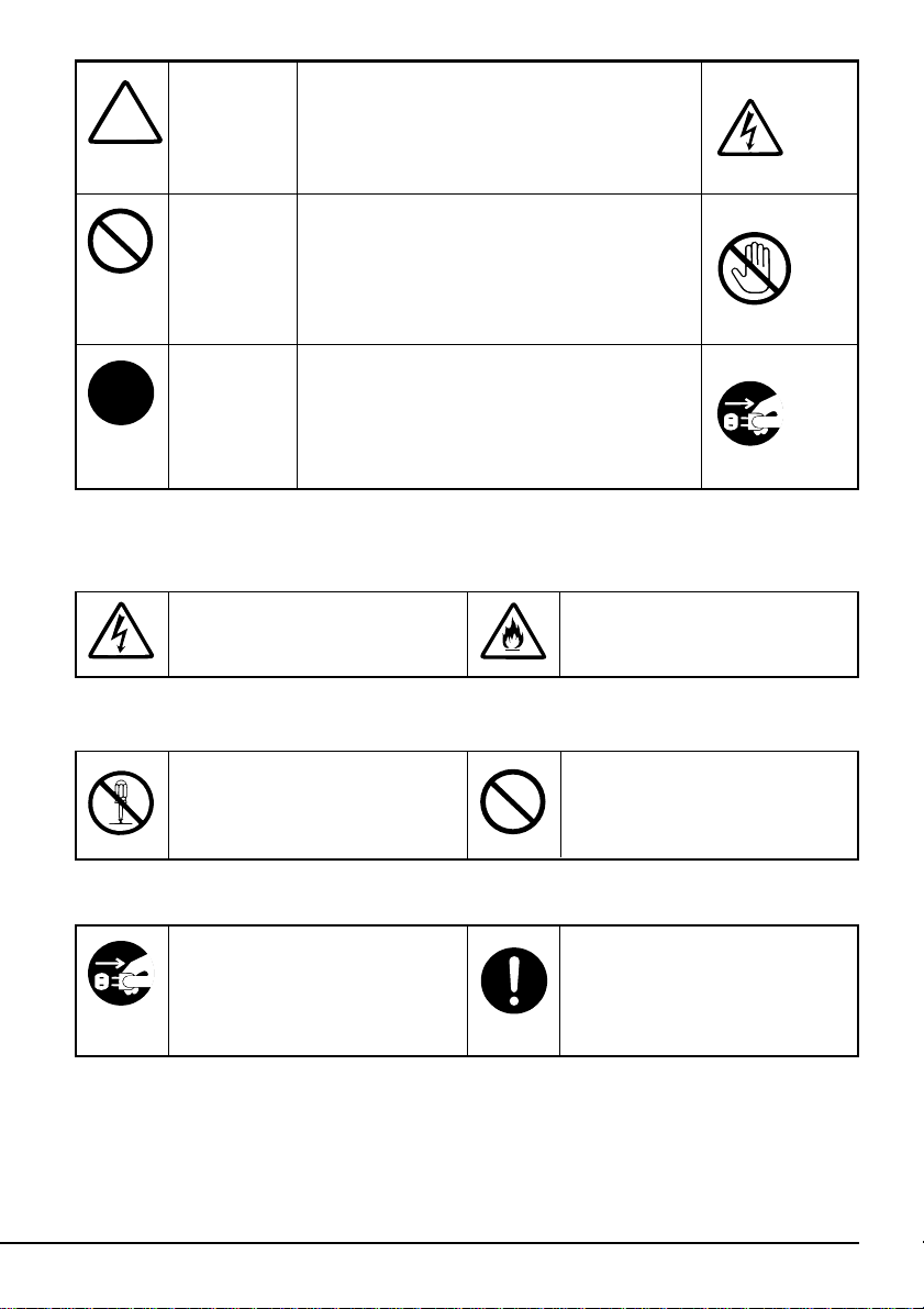
The marks used in this manual and their meaning are shown below.
Indicates that a dangerous situation may occur
if you ignore the instruction. The symbol
illustration indicates the kind of prohibited
danger.
Indicates that the corresponding action is
prohibited. A picture in the symbol illustrates
the inhibited action.
Indicates enforcement of action. The symbol
illustration indicates the kind of enforced
action. The given action is required to avoid
danger.
Awareness of caution
(Example)
(Electric shock)
(Example)
(Do not touch.)
(Example)
(Pull plug.)
Indicates that you may receive an
electric shock if this instruction is
ignored.
Prohibited
Do not disassemble, repair or
remodel the Built-In AIT AutoLoader Unit, as it may cause an
electric shock or fire.
Enforcement
Pull the Built-In AIT Auto-Loader
Unit power plug from the outlet.
Otherwise, a fire may occur or you
may receive an electric shock.
Indicates that the unit may generate
smoke or catch fire if you ignore
the instruction.
Indicates general things you
should not do.
Operate the Built-In AIT AutoLoader Unit in accordance with the
instructions. Otherwise, a fire may
occur or you may receive an
electric shock.
iii
Page 4
Precautions during Use
- Please read this chapter -
The information required to use the Built-In AIT Auto-Loader Unit correctly is described below.
Safety Considerations
To use the Built-In AIT Auto-Loader Unit safely, please read the considerations listed in this
section and fully understand them. For explanations on the symbols, refer to “Safety Indications”
described at the beginning of this manual.
Important
See the instruction manual provided with the basic processing unit on which the N8551-29F BuiltIn AIT Auto-Loader Unit is mounted, in addition to the considerations given herein. The basic
processing unit instruction manual describes the precautions to be taken during mounting/
dismounting the options.
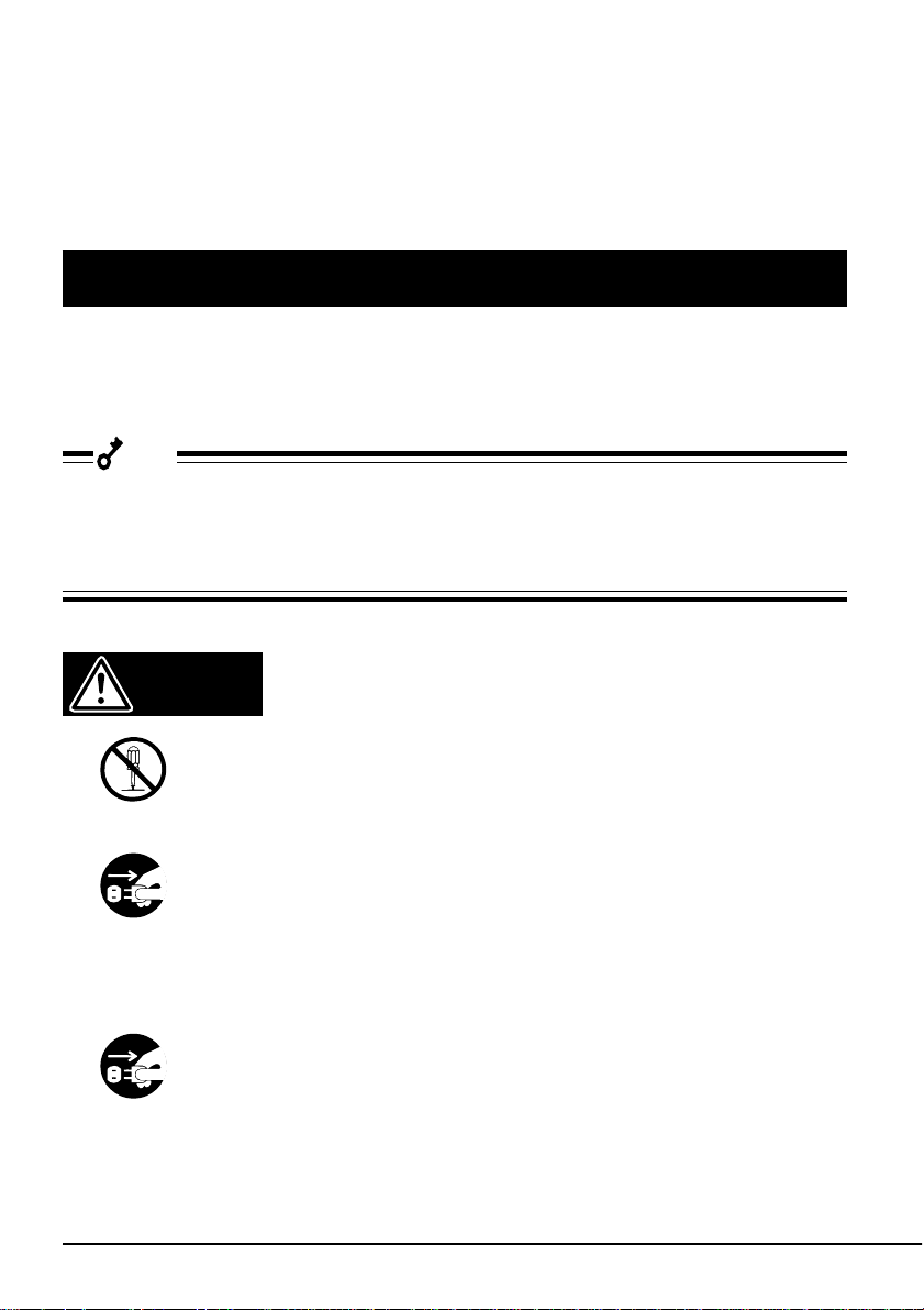
WARNING
■ Do not disassemble or modify the Built-In AIT Auto-Loader Unit.
Do not disassemble or modify the N8551-29F Built-In AIT Auto-Loader Unit.
If you do so, a fire or you may receive an electric shock.
■ Do not use the Built-In AIT Auto-Loader Unit if it emits smoke or a bad, odor
or makes an abnormal noise.
If smoke, odor or abnormal noise is detected, immediately turn off the basic
processing unit and unplug the power cable from the AC outlet. Then, contact
your dealer or the NEC maintenance service company. If a faulty unit is used
continuously, it may cause a fire.
■ Do not use the damaged Built-In AIT Auto-Loader Unit continuously.
If the N8551-29F Built-In AIT Auto-Loader Unit is damaged, immediately
turn off the basic processing unit and unplug the power cable from the AC
outlet. Then, contact your dealer or the NEC maintenance service company.
Using such a faulty unit continuously may cause a fire.
iv
Page 5
WARNING
■ Do not insert a wire or a metal chip into the Built-In AIT Auto-Loader Unit.
Do not insert a foreign material such as a metal chip or wire into the ventilation port or the cartridge slot, as this may cause an electric shock.
■ Do not use the Built-In AIT Auto-Loader Unit at an unsuitable site.
Refer to the instruction manual provided with the basic processing unit and
check that the Built-In AIT Auto-Loader Unit is installed at a suitable site.
Otherwise, a fire and electric shock as well as operational malfunction may be
caused.
■ Do not touch the driver with wet hands.
Do not mount/dismount the Built-In AIT Auto-Loader Unit with wet hands, as
this may cause an electric shock.
CAUTION
■ Connect the cable correctly.
Connect the cable as explained in "Mounting on the basic processing unit" on
page 7 of this manual.
■ Do not bend the cable.
Do not bend, twist, or bind the power and connection cables. Also, do not put
a load on the cable or catch the cable between things. The cable could be
damaged, and this may cause a fire or electric shock.
■ Do not connect or disconnect the cable without removing the plug
When connecting or installing the basic processing unit and peripheral
devices, make sure you unplug the power cord that is connected to the basic
processing unit. To avoid electric shock, do not connect or disconnect the
cable while the power cord is plugged in.
■ Do not used damaged cables
Before connecting cables, check that the connector is not damaged, the
connector pins are not bent, and that the connector is not dirty. If the connector is damaged, the pins are bent, or the connector is dirty, the connector may
short and cause a fire.
v
Page 6
CAUTION
■ Plug-in the connector up to the end.
Plug-in the cable connector firmly up to the end. If you plug-in the connector
halfway, the poor contact causes the Built-In AIT Auto-Loader Unit to be
heated up and may result in a fire. If dust collects on the outlet, it may be
heated when it comes in contact with water drops and cause a fire.
■ Do not hold the cable when unplugging it.
Hold the connector head when plugging or unplugging the power cable and
connection cables. The cable may be damaged if it is pulled, which may cause
a fire or electric shock.
■ Do not short circuit the connector pins.
This may cause a fire or electric shock.
■ Do not mount the Built-In AIT Auto-Loader Unit on a unit other than the
specified one.
If you mount it on an unauthorized unit, a malfunction, fire and electric shock
may be caused.
■ Do not block the fan.
Do not block the fan on the rear of the Built-In AIT Auto-Loader Unit. The
inner temperature will rise and may cause a malfunction, fire and electric
shock.
■ Do not put water or foreign materials in the Built-In AIT Auto-Loader Unit.
Do not put water/other liquids or foreign materials such as pins and clips in
the Built-In AIT Auto-Loader Unit. This may cause a fire, electric shock or
failure. If such an object is inserted by mistake into the Built-In AIT AutoLoader Unit, immediately turn off the power and unplug the power cable from
the outlet. Leave the Built-In AIT Auto-Loader Unit as it is (do not disassemble it) and contact your dealer or the NEC maintenance service company.
■ Do not touch the Built-In AIT Auto-Loader Unit during lightning.
If lightning is likely to occur, unplug the power cable from the outlet. If
lightning starts before you have unplugged the power cable, do not touch the
entire unit including the cables. Otherwise, a fire or electric shock may be
caused.
vi
Page 7

CAUTION
■ Do not store the Built-In AIT Auto-Loader Unit in a dusty, humid place.
Do not store the Built-In AIT Auto-Loader Unit in a humid place, for example,
near a hot water supply. If you reinstall the Built-In AIT Auto-Loader Unit, a
fire may be caused.
■ Do not use cellular phones or pagers near the unit
Do not use cellular phones or pagers near this unit. Doing so may cause a
machine malfunction.
vii
Page 8

For Correct Operation
To operate the N8551-29F Built-In AIT Auto-Loader Unit correctly, observe the following points.
For considerations on handling the AIT data cartridge, refer to the chapter “AIT Data Cartridge”.
Main unit
• Set the SCSI ID of the N8551-29F Built-In AIT Auto-Loader Unit so that it is not similar to the
SCSI IDs of other SCSI equipment.
→ Otherwise, an operation error will occur.
• Before setting the magazine on the N8551-29F Built-In AIT Auto-Loader Unit, check that four
AIT cartridges are set in the magazine.
→ If the magazine in which only three or less cartridges are contained is set, a machine failure
or damage of the backup data may be caused.
• Do not turn off the power to the basic processing unit when the BUSY lamp on the front of the
Built-In AIT Auto-Loader Unit is ON or blinking.
→ This may cause a machine failure or damage of the backup data.
• Do not store the Built-In AIT Auto-Loader Unit in a place exposed to direct sunlight.
→ The Built-In AIT Auto-Loader Unit may not be able to operate correctly.
• Do not store the Built-In AIT Auto-Loader Unit in a place subject to corrosive gas, chemicals or
splashing of chemicals.
→ The Built-In AIT Auto-Loader Unit may get deformed or damaged and may not operate
correctly.
• Do not store the Built-In AIT Auto-Loader Unit in a place subject to strong vibrations.
→ This may cause machine failure.
• Do not put a load on the Built-In AIT Auto-Loader Unit when using or storing it.
→ This may cause machine failure.
• Do not store the Built-In AIT Auto-Loader Unit in a place subject to drastic temperature
fluctuations.
→ This may cause machine failure.
• Use the “AIT Data Cartridge (model: AIT2, AIT1)” as the Built-In AIT Auto-Loader Unit data
cartridge.
→ If you use a data cartridge of another make, a read/write error may occur.
• Use the “AIT Cleaning Cartridge” for cleaning the Built-In AIT Auto-Loader Unit.
→ If you use a cleaner of another make, a machine failure may occur.
viii
Page 9

• Do not move the unit with the cartridges and magazine set.
→ If the unit is subject to shock, the unit and cartridges may be damaged.
• Remove the cartridges from this unit when not using it, or before turning off the power.
→ Not doing so may shorten the life of your cartridges and cause a machine malfunction.
When using the Built-In AIT Auto-Loader Unit, remove the magazine, or make sure the
cartridge is returned to the magazine before turning off the power.
• Do not leave the cartridges and magazine protruding from the unit’s magazine slot for extended
periods of time.
→ This may shorten the life of your cartridges and cause a machine malfunction.
Magazine
• Do not insert the magazine in the Built-In AIT Auto-Loader Unit when a cartridge is ejected
from the magazine slot.
→ This will cause machine failure or operation error.
• Do not store the magazine in a dusty, humid place or in a place subject to direct sunlight.
→ Data within the data cartridge set in the magazine may be damaged.
• Do not store the magazine in a place subject to drastic temperature fluctuations.
→ Data within the data cartridge set in the magazine may be damaged.
• Do not store the magazine in a place subject to strong vibrations.
→ The magazine may be damaged and data within the data cartridge set in the magazine may
be damaged.
• Do not store the magazine in a place subject to corrosive gas, chemicals or splashing of chemicals.
→ The magazine may get deformed or damaged and may not operate correctly. Data within
the data cartridge set in the magazine may be damaged.
• Store the magazine in the provided case.
→ Data within the data cartridge set in the magazine may be damaged.
• Store the magazine in the special magazine case.
→ Not doing so may damage the magazine.
• Do not put a load on the magazine when using or storing it.
→ Data within the data cartridge set in the magazine may be damaged.
ix
Page 10
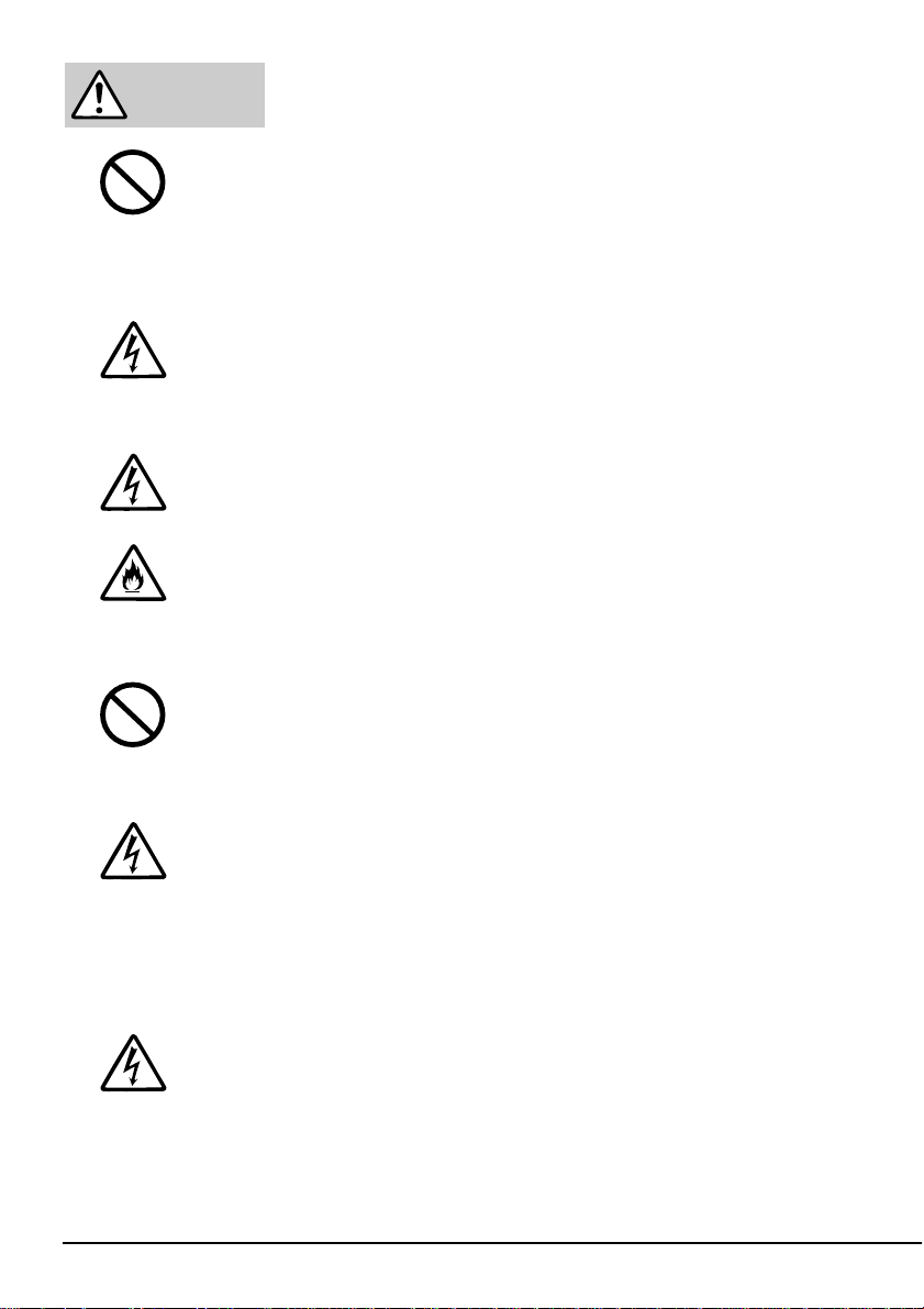
• If the magazine write protect plug is set to Write Disabled, data cannot accidentally be written to
the data cartridges inserted in the magazine. (Even if the data cartridge write protect plug is set
to Write Enabled, data cannot be written to the data cartridge if the magazine’s write protect
plug is set to Write Disabled.)
REC
Write Enabled Write Disabled
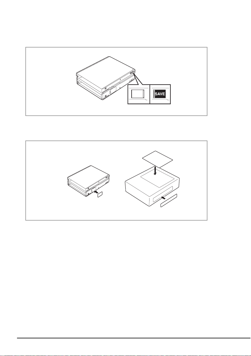
• It is recommended that you should label the magazine so that you can check the contents of the
data cartridge set in the magazine.
Magazine Case
• Use the magazine specially designed for the N8551-29F Built-In AIT Auto-Loader Unit.
→ If you use a magazine of another make, a read/write error may occur. In addition, data may
be damaged and Built-In AIT Auto-Loader Unit and magazine failure may occur.
x
Page 11

Others
Transfer to a third party
When you transfer (or sell) the N8551-29F Built-In AIT Auto-Loader Unit to a third party, be sure
to include the instruction manual with the driver.
Disposal of consumed parts and equipment
For the disposal of the N8551-29F Built-In AIT Auto-Loader Unit and its cartridge, observe the
waste disposal rules of your local government. For details, contact the local government office.
Important
If a driver failure occurs because you have used a device or interface cable of another manufacturer (the third party) or those which have not been approved by NEC, you may not be provided
with the NEC warranty service.
xi
Page 12

Trademarks
Advanced Intelligent Tape is a trademark of the Sony Corporation.
The company and product names contained in this manual are trademarks or registered trademarks
of the respective companies.
All names used in the sample applications are fictitious. They have no relation with any product,
party or individual names.
Remarks
(1) Reproduction of this document or portions thereof without prior approval is prohibited.
(2) The information contained in this document is subject to change at any time, without prior
notice.
(3) Reprinting or changing of this document without prior approval of NEC is prohibited.
(4) All efforts have been made to ensure that the contents of this manual are correct; however,
should any doubts arise, or errors or missed entries be detected, NEC would greatly appreciate
it if our dealers are informed about it.
(5) Please note that in no event shall NEC be liable for any damages whatever arising out of the
use of this device, regardless of item (4) above.
© NEC Corporation 2000
xii
Page 13

Introduction
Thank you for purchasing the N8551-29F Built-In AIT Auto-Loader Unit.
The Built-In AIT Auto-Loader Unit will ensure smooth backup, application and management of
your important data.
To maximize the N8551-29F Built-In AIT Auto-Loader Unit functions, please read the instruction
manual carefully before use and fully understand how to handle the device.
xiii
Page 14

Organization of the Instruction Manual
The instruction manual function as a guide that enables you to set up and use the N8551-29F BuiltIn AIT Auto-Loader Unit correctly. You can refer to this manual whenever you encounter a
question or problem during setup and daily operation.
The instruction manual consists of two chapters: the first covers the considerations on the safe use
of the Built-In AIT Auto-Loader Unit (setup, daily operation and maintenance) and the second
covers the considerations on the safe use of the AIT data cartridge available on the Built-In AIT
Auto-Loader Unit (operation and maintenance).
Order of priority when the N8551-29F Built-In AIT Auto-Loader Unit is used for the first time
When the Built-In AIT Auto-Loader Unit is being used first time, refer to the instruction manual in
the following sequence to perform the setup after unpacking the driver.
1. Check the contents in the package. ................................. Package Contents (→P. xvi)
2. Learn the operational precaution. ................................... Precautions during Use (→ P. iv)
3. Learn the parts of the Built-In AIT Auto-Loader Unit.... Part Name and Function (→ P. 2 to 3)
4. Set before installation. .................................................... Setup (→ P. 4 to 7)
5. Install the driver in the basic processing unit.................. Setup (→ P. 7 to 10)
6. Learn how to handle the cartridge................................... AIT Data Cartridge (→ P. 29)
7. Set the cartridge. ............................................................. Handling (→ P. 11 to 18)
8. Check the LCD and lamp indication............................... LCD (→ P. 18)
Check the lamp indication. ............................................. Handling (→ P. 20)
9. Change the Built-In AIT Auto-Loader Unit settings....... Changing Settings (→ P. 21 to 25)
10. Clean the Built-In AIT Auto-Loader Unit....................... Cleaning (→ P. 26)
For details on data storage methods and settings, such as data save format, refer to
the instruction manual provided with the backup software.
xiv
Page 15

Symbols used in the texts
Three types of symbols are used in the manual. Each symbol denotes the following. (For indications concerning safety, see the beginning of the manual.)
✔
Important
Check
Hint
✎
Indicates the points which must be observed when handling the Built-In AIT
Auto-Loader Unit and the issues to which special attention must to be paid.
Indicates the points which you should check when handling the Built-In AIT
Auto-Loader Unit .
Indicates useful information and operational help.
xv
Page 16
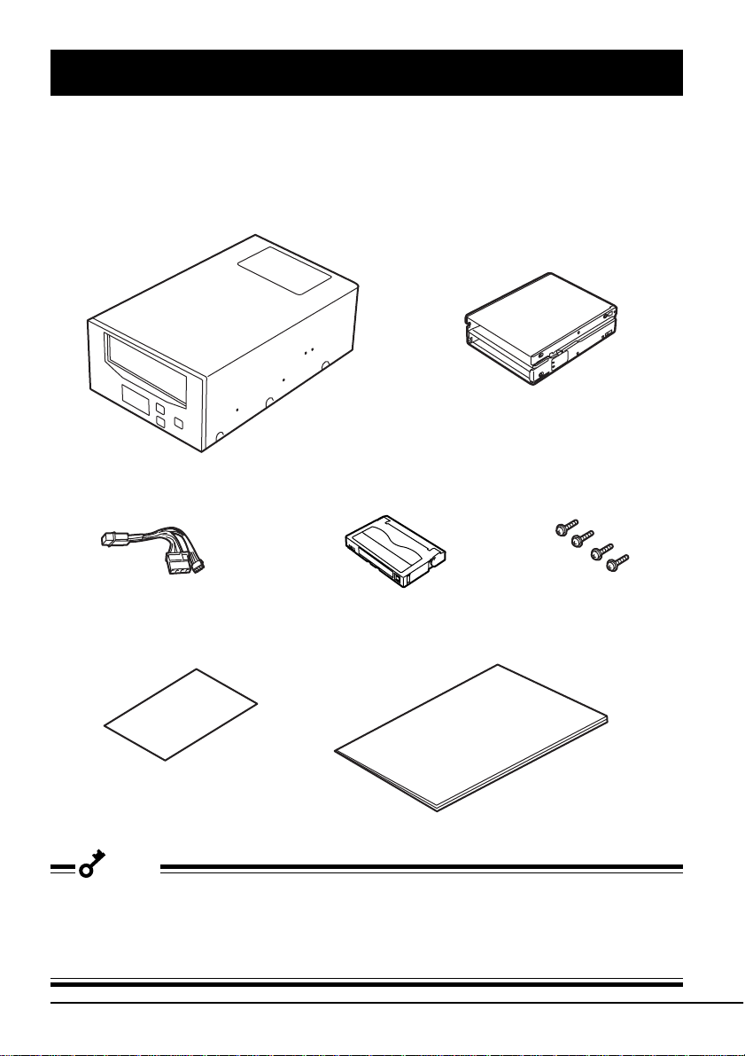
Package Contents
Many accessories are included with the main Built-In AIT Auto-Loader Unit in the N8551-29F
Built-In AIT Auto-Loader Unit. Verify the packed contents with the part list given below and
ensure that all the components and parts are present. Also, check that each item is undamaged. If
a component or part is missing or damaged, contact your dealer.
N8551-29F Built-In AIT Auto-Loader Unit
Power Cable
Cleaning cartridge
Instruction manual (this manual)Instructions on handling the AIT unit
Magazine
Screws (4)
Important
• Locking parts contained in the package or box will be required when removing the Built-In AIT
Auto-Loader Unit for transportation. Store them securely.
• Copy a backup from the provided floppy disk. Keep the provided floppy disk as the master disk
and use the backup disk in actual applications.
xvi
Page 17

Table of Contents
Safety Indications ............................................. ii
Precautions during
Use - Please read this
chapter -
Built-In AIT AutoLoader Unit
Safety Considerations .............................................. iv
For Correct Operation............................................ viii
Others ...................................................................... xi
Transfer to a third party ..................................... xi
Disposal of consumed parts and equipment ...... xi
Introduction ........................................................... xiii
Organization of the Instruction Manual................. xiv
Order of priority when the N8551-29F Built-In
AIT Auto-Loader Unit is used for
the first time.................................................. xiv
Symbols used in the texts.................................. xv
Package Contents................................................... xvi
Features..................................................................... 1
Usable Cartridges ..................................................... 1
Part Name and Function ........................................... 2
Front.................................................................... 2
Rear ..................................................................... 3
Bottom ................................................................ 3
Magazine............................................................. 3
Setup ......................................................................... 4
Setting the Built-In AIT Auto-Loader Unit
- Setting with the jumper pins - ....................... 4
Setting the Built-In AIT Auto-Loader Unit
- Setting with the DIP switch - ........................ 6
Mounting on the basic processing unit ............... 7
Handling ................................................................. 11
Setting the AIT data cartridge........................... 11
Ejecting the AIT data cartridge......................... 14
Setting the magazine ......................................... 16
Selecting the AIT data cartridge ....................... 17
Ejecting the magazine ....................................... 18
Reading/writing data......................................... 18
LCD .................................................................. 18
Lamp indication ................................................ 20
(Continued on next page)
xvii
Page 18

Built-In AIT AutoLoader Unit
(Continued)
Changing Settings................................................... 21
Switching to and using the menu screen........... 21
Version - Display the setting status - ................ 22
Auto Load – Auto Load settings –.................... 22
Unload – Unload settings –............................... 23
Contrast - Adjust brightness - ........................... 23
Orientation - Set the display orientation -......... 24
Language - Set the displayed language - .......... 25
Cleaning.................................................................. 26
Cleaning the read/write head ............................ 26
Cleaning the driver............................................ 27
AIT Data Cartridge
Data Cartridge Part Name and Function................. 29
Operation, Storage and Transportation
Requirements .......................................................... 30
Label ....................................................................... 30
Label paste position .......................................... 30
Precautions on entry to label............................. 31
Write-protect........................................................... 31
Precautions on Handling......................................... 32
Operational precautions .................................... 32
General precautions .......................................... 32
Usage Inhibition Standard ...................................... 33
Service Life ............................................................ 33
Storing Important Data ........................................... 34
Managing 3-generation Data .................................. 34
Specification ........................................................... 35
Error Message List ................................................. 36
Customer’s Application Sheet ................................ 37
xviii
Page 19

Built-In AIT Auto-Loader Unit
This chapter explains setup, installation and daily operation of the N8551-29F Built-In AIT AutoLoader Unit.
Features
This unit has the following features:
• You can record large amounts of data on the AIT1 and AIT2 data cartridges using AIT (Advanced Intelligent Tape) format.
• When using the data compression function
Data Cartridge, and 25 to 50 GB of data on the AIT1 Data Cartridge.
• The basic processing unit automatically determines whether data recorded on the AIT data
cartridges is compressed. It can also read data recorded on AIT data cartridges with conventional AIT drives.
*1
The compression rate for recorded data may differ depending on the user environment and
the type of data.
(100 GB can be recorded when using twice the average compression rate (for AIT2 data
cartridges).)
Usable Cartridges
*1
, you can record 50 to 100 GB of data on the AIT2
Please use Sony AIT data cartridges (AIT2 (tape length: 230 m), or AIT1 (tape length: 170 m))
with this unit. Using other types of AIT data cartridges may cause read and write errors.
Built-In AIT Auto-Loader Unit 1
Page 20

Part Name and Function
The Built-In AIT Auto-Loader Unit and magazine have the following parts and functions.
Front
➀
➁
➅
➆
➄ ➂
➃
➀ Magazine slot
A slot in which the magazine is set
(→ P. 16)
➁ EJECT button
Press this button when ejecting the magazine from
the Built-In AIT Auto-Loader Unit. (→ P. 18)
➂ SELECT button
Press this button when selecting which AIT data
cartridge of four mounted on the magazine is to be
used. (→ P. 17)
You can also use this when creating a menu using
a LCD. (→ P. 21)
➃ ENTER button
Press this button when setting the AIT data
cartridge selected with SELECT button in the read/
write drive in within the Built-In AIT Auto-Loader
Unit. (→ P. 17)
You can also use this when creating a menu using
a LCD. (→ P. 21)
2 Built-In AIT Auto-Loader Unit
➄ LCD
An indicator which shows the status of the Built-In
AIT Auto-Loader Unit and the AIT data cartridge set
in the Built-In AIT Auto-Loader Unit (→ P. 18)
You can also use this when creating a menu using
a LCD. (→ P. 21)
The LCD shows an error message when an error
occurs in the Built-In AIT Auto-Loader Unit.
(→ P. 36)
➅ BUSY lamp
An indicator which shows the data communication
status (→ P.20)
➆ TAPE lamp
An indicator which shows the status of the AIT data
cartridge (→ P. 20)
Page 21

Rear
Bottom
➀
➄ ➂
➁
➂
➃
12345678
ON
➀
➀ Unused connector
Do not connect anything.
➁ Fan
➂ Power connector
Connect the provided power relay
cable. (→ P. 9 )
➃ Jumper pin
Pins which set the Built-In AIT AutoLoader Unit (→ P. 4)
➄ SCSI connector
Connect the driver’s built-in SCSI
cable. (→ P. 9 )
➀ DIP switch
Switches which set the Built-In AIT
Auto-Loader Unit (→ P. 6)
Magazine
➃
➁➂ ➀
➀ Write-protect plug
A switch which enables/disables
writing to the inserted AIT data
cartridge (→ P. ix)
➁ Data cartridge slot
A slot into which an AIT data
cartridge is inserted (→ P. 11)
➂ Release switch
Press this switch when ejecting the
inserted AIT data cartridge. (→ P. 14)
➃ Safety lock
This hook prevents magazines with
incorrectly set AIT data cartridges
from being inserted into this unit.
(→ P. 13)
Built-In AIT Auto-Loader Unit 3
Page 22

Setup
The procedure up to installation of the driver to the “basic processing unit” is explained in the
following.
Setting the Built-In AIT Auto-Loader Unit
You can change the following settings with the jumper pins on the rear of the Built-In AIT AutoLoader Unit.
• SCSI ID (factory-set to “ID4”)
• Parity function (factory-set to “Enabled”)
- Setting with the jumper pins -
SCSI ID (pin 0 to 3 from right)
Unused (NC)
Parity (PD)
Hint
✎
Hint
✎
“With strap” means a status that the straps are attached to two pins. “Without strap” means a
status that no strap is attached to either pin or it is attached to one of two pins.
“Without strap” means that one strap is
attached to one of the two pins, or that the
strap has been removed altogether. If you
remove the strap, make sure you store it in
a safe place.
4 Built-In AIT Auto-Loader Unit
Page 23

Setting SCSI ID
Set SCSI ID which is used by the Built-In AIT Auto-Loader Unit. Use four jumper pins, pin 0 to
pin 3, on the rear of the Built-In AIT Auto-Loader Unit.
Pin 3 (Factory-set to “Without strap”)
Pin 2 (Factory-set to “With strap”)
Pin 1 (Factory-set to “Without strap”)
Pin 0 (Factory-set to “Without strap”)
✔
Check
Check that the Built-In AIT Auto-Leader Unit’s SCSI ID is not duplicated with SCSI ID of other
SCSI device.
SCSI ID Pin 3 Pin 2 Pin 1 Pin0
0 ✕✕✕✕
1 ✕✕✕❍
2 ✕✕❍✕
3 ✕✕❍❍
*1
4
5 ✕❍✕❍
6 ✕❍❍✕
*2
7
8 ❍✕✕✕
9 ❍✕✕❍
10 ❍✕❍✕
11 ❍✕❍❍
12 ❍❍✕✕
13 ❍❍✕❍
14 ❍❍❍✕
15 ❍❍❍❍
✕❍✕✕
✕❍❍❍
❍ : With strap
✕ : Without strap
*1
: Factory-set value
*2
: Do not set SCSI ID to ID7.
Built-In AIT Auto-Loader Unit 5
Page 24

Setting the parity function
Set the parity function using the leftmost jumper pin on the rear of the Built-In AIT Auto-Loader
Unit.
The parity function is “Enabled” when setting “Without strap” (factory-set value). The parity
function is “Disabled” when setting “With strap”.
PD (Factory-set to “Without strap”)
Important
To improve reliability, set the parity function “Enabled” (Without strap).
Setting the Built-In AIT Auto-Loader Unit
- Setting with the DIP switch -
The DIP switch on the bottom of the Built-In AIT Auto-Loader Unit enables you to change the
following settings.
• Terminator Power (Terminator power supply) (Factory-set to ON)
• DC Control (1) (Data compression setting) (Factory-set to ON)
• DC Control (2) (Data compression setting) (Factory-set to OFF)
ON
12345678
Switches 1 to 4: Unused
Switch 5: Terminator Power
Switch 6: Unused
Switch 7: DC Control (1)
Switch 8: DC Control (2)
6 Built-In AIT Auto-Loader Unit
Page 25

Setting terminator power - Terminator Power -
12345678
ON
12345678
ON
Set whether terminator power is supplied to the SCSI bus or not.
Use Switch 5. Setting Switch 5 to ON (factory-set to ON) will
supply terminator power; setting Switch 5 to OFF will not supply
terminator power.
* When this unit is installed in the N8541-28F device expansion
unit, set this switch to OFF if you want to use the slaved power
control feature.
Setting data compression - DC Control (1) -
Set whether the Built-In AIT Auto-Loader Unit’s data compression
function is enabled or disabled.
Use Switch 7. Setting Switch 7 to ON (factory-set to ON) will
enable the data compression function; setting Switch 7 to OFF will
disable the terminator data compression function.
Setting data compression - DC Control (2) -
Set whether control of data compression from the backup software
is enabled or disabled.
Use Switch 8. Setting Switch 8 to ON will disable control of data
compression from the backup software; setting Switch 8 to OFF
(factory-set to OFF) will enable control of data compression from
the backup software.
ON
12345678
Mounting on the basic processing unit
CAUTION
Before installing this unit, make sure you unplug the power plug for the basic
processing unit you are using (such as a server or workstation basic processing
unit). Leaving the power cord plugged in presents an electrical shock hazard.
Mount the Built-In AIT Auto-Loader Unit on the basic processing unit.
Important
When mounting N8551-29F Built-In AIT Auto-Loader Unit on Express 5800/130/140/150/ 170/180
Pro, do not attach it to the bottom of 5.25-inch device bay.
Built-In AIT Auto-Loader Unit 7
Page 26

1 Turn off the basic processing unit and pull the power cable from the outlet.
2 Remove the cover from the basic processing unit.
3 Remove the cover from the 5.25-inch device bay of the basic processing unit.
4 Remove the mounting reel of the 5.25-
inch device bay of the basic processing
unit.
5 Mount the mounting reel removed in
step 4. on the Built-In AIT Auto-Loader
Unit.
Example of the mounting reel of the basic
processing unit (The mounting reel may differ
from the following illustration depending on the
type of basic processing unit you are using.)
Mounting reel
✔
Check
• Fix the mounting reel so that the reel
end is positioned as shown below.
• Use provided four M3 screws.
8 Built-In AIT Auto-Loader Unit
5.25-inch device front cover
Built-In AIT AutoLoader Unit surface
Mounting reel end
Page 27

6 Insert the Built-In AIT Auto-Loader
Unit into the 5.25-inch device bay slot
of the basic processing unit.
When you hear a click sound, the BuiltIn AIT Auto-Loader Unit is locked.
<when mounting the Built-In AIT Auto-Loader Unit horizontally>
<when mounting the Built-In AIT Auto-Loader Unit vertically>
7 Connect the cable.
Connect two-branched connectors of
the provided power relay cable to the
power connector on the rear of the
Built-In AIT Auto-Loader Unit and the
other side of the power relay cable to
the power cable connector of the basic
processing unit.
✔
Check
This unit does not have a built-in
terminator. When connecting this unit to
the last terminal of the SCSI bus
terminal, attach a terminator to the end of
the SCSI cable.
SCSI cable
Power relay cable
Power cable of the basic
processing unit
Built-In AIT Auto-Loader Unit 9
Page 28

8 Attach the cover to the basic processing unit. Plug the power cable to the outlet.
9 Turn on the basic processing unit.
10 When the SCSI bus can be set on the side of the basic processing unit, set the following on the
driver.
• Transfer rate : 40 MByte/second (max., synchronous)
• Data bus width : 16 bits (Ultra Wide SCSI, LCS/SE)
• DISCONNECT/RECONNECT function : Enable
For details, see the instruction manual provided with the basic processing unit.
Hint
✎
The orientation of the Built-In AIT Auto-Loader Unit’s LCD can be changed so that it fits the BuiltIn AIT Auto-Loader Unit’s installation orientation in the basic processing unit (see P. 24).
✔
Check
Set the maximum transfer rates as follows according to the number of devices connected to the
bus and the SCSI cable length.
SCSI ID
Ultra Wide SCSI 40 16 3 (-) 4
Ultra Wide SCSI 40 16 1.5 (-) 8
Ultra Wide SCSI 40 16 - (3) 16
Fast Wide SCSI 20 16 3 (3) 16
Wide SCSI 10 16 6 (3) 8
* When the SCSI host and all devices connected to the same bus are LVD-compatible.
Maximum transfer Data bus Maximum cable
rate (Mbyte/s) width (bit) length (m) of devices
Single-ended (SCSI host +
(LVD*) number of
Maximum number
10 Built-In AIT Auto-Loader Unit
devices)
Page 29

Handling
The following explains how to handle the N8551-29F Built-In AIT Auto-Loader Unit.
Setting the AIT data cartridge
Important
• As the data cartridge to be set in the magazine, use our “AIT Data Cartridge”. If you use a data
cartridge of other manufacturer, a read/write error may occur.
• Set four AIT cartridges in the magazine. If setting the magazine in which only three or less
cartridges are contained, a machine failure or damage of backup data may be caused.
• The AIT data cartridges set in the magazine are assigned numbers as below. Do not set them
in the wrong order.
Cartridge 3
Cartridge 2
✔
Check
When write-protect is enabled using the AIT data cartridge write-protect plug so that you cannot
write data in the data cartridge, the write-protect indicator lights after the magazine is set in the
driver.
3
2
WP lights.
4
1
Cartridge 4
Cartridge 1
Write-protect plug (Sliding it up writeprotects the cartridge.)
(→ 31 page)
Built-In AIT Auto-Loader Unit 11
Page 30

1 Check that the magazine and cartridge
insertion orientation is as shown at
right.
2 Insert AIT data cartridges No. 1 and
No. 2 into the lower row of the
magazine in this order.
3 Insert AIT data cartridges No. 3 and
No. 4 into the upper row of the
magazine in this order.
Important
• Insert the AIT data cartridges in the correct orientation.
<Wrong examples>
12 Built-In AIT Auto-Loader Unit
<Continue to the next page>
Page 31

Important
• If the AIT data cartridges are not set correctly in
the magazine, the safety lock on the magazine is
protruding, preventing the magazine from being
inserted into this unit. Check that the safety lock is
not protruding before inserting the magazine.
Further, do not force the magazine into this unit
when the safety lock is protruding. This will result
in damaging the safety lock, the magazine and
other components, and the AIT data cartridges.
• The following precautions are written on the top
of the magazine.
Insert cartridges carefully.
Do not insert the magazine when a cartridge is
ejected. This may cause a machine failure or
operational malfunction.
Safety lock
• Do not swing around the magazine in which the AIT data cartridges are set.
✔
Check
• After insertion, check that the AIT data cartridges will
not come off by turning over the magazine slot.
• Check that no cartridge is ejected from the magazine
slot.
Built-In AIT Auto-Loader Unit 13
Page 32

Ejecting the AIT data cartridge
Eject the AIT data cartridge set in the
magazine as shown below.
1 Direct the magazine bottom toward
you and hold the magazine uprightly.
✔
Check
Do not face the magazine slot downward when ejecting the cartridge. The
cartridge may fall and get damaged.
2 While holding down the release key
on the magazine, push out the
cartridge along the magazine groove.
AIT data cartridge No. 1 is slightly
ejected from the slot.
3 Remove the cartridge from the
magazine by holding its both edges.
14 Built-In AIT Auto-Loader Unit
Page 33

4 In the same manner as in step 2,
push out AIT data cartridges No. 2
and No. 3 and remove them from the
magazine.
5 Face the magazine slot upward.
Shake it up and down and apply a
soft material such as a palm to the
magazine.
Then, the AIT data cartridges set in
the upper row shift down to the
lower row.
6 In the same manner as in step 2,
push out AIT data cartridge No. 4
and remove it from the magazine.
Built-In AIT Auto-Loader Unit 15
Page 34

Setting the magazine
Set the magazine in which four AIT data cartridges are contained in the Built-In AIT Auto-Loader
Unit. By inserting the magazine to the extent, the data cartridge is automatically set in the Built-In
AIT Auto-Loader Unit and the TAPE lamp lights.
Important
Be sure to set four AIT data cartridges in the magazine. If setting the magazine in which only
three or less cartridges are contained, a machine failure or damage of backup data may be
caused.
✔
Check
When write-protect is enabled using the AIT data
cartridge write-protect plug so that you cannot write
data in the data cartridge, the write-protect indicator
lights after the magazine is set in the Built-In AIT
Auto-Loader Unit.
REC
WP lights.
Write-protect plug (Sliding it to display
“SAVE” enables write-protect.)
1 Turn on the basic processing unit. Check that the driver’s BUSY lamp and TAPE lamp go off.
2 Insert the magazine into the Built-In
AIT Auto-Loader Unit’s slot in the
orientation as shown at right.
By inserting the magazine to the
extent, the data cartridge is automatically set in the Built-In AIT
Auto-Loader Unit.
“Magazine Loading” appears in the
LCD. The basic processing unit
starts checking the AIT data
cartridges in the magazine.
When “scan4 OK” appears in the
LCD and all cartridge numbers (1 to
4) light, the cartridges are completely set.
16 Built-In AIT Auto-Loader Unit
Page 35

Hint
✎
• The cartridges are checked in the order of cartridge number (1 to 4).
• In the LCD, the cartridge number being checked is blinking.
3 Using the backup application, or the button and the LCD on the front of the Built-In AIT Auto-
Loader Unit, select the AIT data cartridges to be used and set them in the read/write drive.
When using the backup application, refer to the instruction manual provided with the applica-
tion. When using the button and the LCD on the front of the driver, refer to “Selecting the AIT
data cartridge” described below.
Selecting the AIT data cartridge
AIT data cartridges set in the magazine can be selected from the backup application on the basic
processing unit.
They can also be selected using the button and the LCD on the front of the Built-In AIT AutoLoader Unit.
Select the cartridges as shown below.
✔
Check
• The Built-In AIT Auto-Loader Unit does not function at all by pressing the SELECT button in the
following situations:
- Within 75 seconds after setting the magazine
- When “Ready” does not appear in the LCD
- While the BUSY lamp is blinking
• The Built-In AIT Auto-Loader Unit does not function at all by pressing the ENTER button while
the BUSY lamp is blinking.
1 Press the SELECT button
The AIT data cartridge number appears in the LCD. Every time you press the SELECT button,
the cartridge number is changed.
2 Check the selected cartridge number and press the ENTER button.
The AIT data cartridge preset in the read/write drive is returned to the magazine. The AIT data
cartridge selected in the LCD is then automatically set in the read/write drive.
Built-In AIT Auto-Loader Unit 17
Page 36

Ejecting the magazine
To eject the magazine from the Built-In
AIT Auto-Loader Unit, press the EJECT
button.
A message “Magazine Ejecting” appears
in the LCD. The AIT data cartridge set
in the read/write drive is returned to the
magazine. Then, the magazine is
automatically ejected from the Built-In
AIT Auto-Loader Unit. Hold the
magazine firmly and remove it from the
Built-In AIT Auto-Loader Unit.
✔
Check
• It may take about 2 minutes until the magazine is ejected from the Built-In AIT Auto-Loader Unit
after pressing the EJECT button.
• The Built-In AIT Auto-Loader Unit does not do anything by pressing the EJECT button while the
BUSY lamp is blinking.
Reading/writing data
To read/write the data from/to the AIT cartridge and compress the data to be written, refer to the
instruction manual provided with the backup software.
LCD
The LCD on the front of the Built-In AIT Auto-Loader Unit allows you to check the status of the
driver and AIT data cartridges. (As shown below, you can change the LCD display orientation
along with the Built-In AIT Auto-Loader Unit installation orientation. For details, refer to P. 24.)
➀
➅
➆
Horizontal display Vertical display
18 Built-In AIT Auto-Loader Unit
➁
➂
➃
➄
➀
➆
➃
➄
➂
➅
➁
Page 37

➀Message area
Displays the Built-In AIT Auto-Loader Unit status. According to the situation, a warning
message or error message (refer to P. 36) appears.
You can change the language of displayed messages to English, French, German, or Spanish
(refer to P. 25).
➁Cartridge number indicator
Displays the status of the AIT cartridge set in the magazine. While the cartridge is being
replaced, the corresponding cartridge number is blinking. When the cartridge is set from the
magazine to the read/write drive, the corresponding cartridge number goes off. When the
cartridge is returned to the magazine, the cartridge number lights again.
➂Write-protect indicator
Lights when the AIT cartridge or the magazine is write-protected. To enable the write-protect
function, use the write-protect tab of the AIT cartridge or the magazine.
➃AIT cartridge types
Displays the type of AIT data cartridge (AIT1 or AIT2) set in the read/write drive.
➄Data compression indicator
Lights when the Built-In AIT Auto-Loader Unit can use the data compression function or it is
running in the data compression mode.
➅Tape position indicator
Estimates the residual capacity of the AIT data cartridge set
in the read/write drive.
Much left
Half left
Almost none
➆Cartridge indicator
Lights when the AIT cartridge is set in the read/write drive. Indicates the tape running status.
Blinks while the AIT cartridge is being inserted/ejected into/from the read/write drive.
Built-In AIT Auto-Loader Unit 19
Page 38

Lamp indication
Two lamps on the front of the Built-In AIT Auto-Loader Unit signal the status of the Built-In AIT
Auto-Loader Unit and AIT data cartridges.
BUSY lamp (green)
Lights when the SCSI interface is enabled. Blinks while the AIT cartridge set in the read/write
drive is being read, written or searched, or while the tape is rewinding.
TAPE lamp (green)
Lights when the AIT cartridge is set in the read/write drive. Blinks while the AIT cartridge is being
inserted into or ejected from the read/write drive.
20 Built-In AIT Auto-Loader Unit
Page 39

Changing Settings
Version
Auto Load
Unload
Contrast
Orientation
Language
You can change the driver’s various settings by switching the LCD indication (on the front of the
driver) to the menu screen. You can also check the version of the program within the Built-In AIT
Auto-Loader Unit (firmware) and the preset SCSI ID.
Switching to and using the menu screen
Display the menu screen as shown below.
Hint
✎
Before switching the LCD to the menu screen, it is recommended that you should remove the
magazine from the Built-In AIT Auto-Loader Unit. When the magazine is set in the Built-In AIT
Auto-Loader Unit, you can display the menu screen to change and check settings only when
“Ready” appears in the LCD. However, to change the setting of “Language”, you must remove the
magazine in advance.
1 Check that the basic processing unit is ON.
2 Hold down the SELECT button for 5 seconds.
The LCD indication is switched to the menu screen.
3 Press the SELECT button to place the cursor ( ) at the
required item.
4 Press the ENTER button.
The sub menu of the selected item appears.
5 Change the setting.
For operations and functions on each screen, refer to the
explanation described below.
Hint
✎
If you do nothing on the screen, the screen returns to the standard indication.
Built-In AIT Auto-Loader Unit 21
Page 40

Version - Display the setting status -
Auto Load
OFF
ON
When selecting “Version” from the menu screen, the sub
menu as shown at right appears.
On this screen, you can check the Built-In AIT Auto-Loader
Unit’s model code, preset SCSI ID number and firmware
version.
After checking the data displayed, press the EJECT button.
The “Version” sub menu returns to the menu screen.
Auto Load – Auto Load settings –
When selecting “Auto Load” from the menu screen, the sub
menu appears as shown on the right.
On this screen, you can set operations for the first cartridge
after you have inserted the magazine.
OFF: Only checks the cartridges in the magazine. (Default
setting)
Use this mode for normal operation.
ON: The first cartridge is automatically loaded into the
read or write drive after the cartridges in the magazine
have been checked.
TSL-A500C
SCSI ID#5
Ver. 0000
Firmware version
SCSI ID number
Model code
1 Press the SELECT button to place the cursor ( ) at the required item. To cancel the selection
and return to the menu screen, press the EJECT button.
2 By pressing the ENTER button after selection, the setting value is saved and the menu screen
appears again.
22 Built-In AIT Auto-Loader Unit
Page 41

Unload – Unload settings –
Unload
Continuous
OFF
ON
Contrast
Adjustment
When selecting “Unload” from the menu screen, the sub
menu appears as shown on the right.
On this screen, you can set cartridge operations using the
Unload command when the fourth cartridge is loaded in the
read/write drive.
OFF: The cartridge is returned to the magazine, and the
command finishes. (Default setting)
Use this mode for normal operation.
ON: The cartridge is returned to the magazine, and the first
cartridge is loaded into the drive.
1 Press the SELECT button to place the cursor ( ) at the required item. To cancel the selection
and return to the menu screen, press the EJECT button.
2 By pressing the ENTER button after selection, the setting value is saved and the menu screen
appears again.
Contrast - Adjust brightness -
When selecting “Contrast” from the menu screen, the sub
menu as shown at right appears.
On this screen, you can control the LCD brightness
(contrast).
Every time you press the SELECT button, the black
indicator scales increase to brighten the screen. By pressing
the SELECT button when the seven indicator scales turn
black, all of them turn white again. (Contrast returns to the
darkest setting.)
After controlling contrast, press the EJECT button to save
the current setting and return to the menu screen.
Built-In AIT Auto-Loader Unit 23
Page 42

Orientation - Set the display orientation -
When selecting “Orientation” from the menu screen, the sub
menu as shown below appears.
On this screen, you can set the LCD orientation along with
the Built-In AIT Auto-Loader Unit installation orientation.
Hint
✎
When the orientation is set in the menu, the top of the BuiltIn AIT Auto-Loader Unit is always displayed upward.
Set “Horizontal” when the Built-In AIT Auto-Loader
Unit is installed horizontally.
Orientation
Horizontal
R-side down
L-side down
Set “R-side down” when the Built-In AIT Auto-Loader Unit
is installed vertically with its right side down.
24 Built-In AIT Auto-Loader Unit
Page 43

Set “L-side down” when the Built-In AIT Auto-Loader Unit
Orientation
English
French
German
Spanish
is installed vertically with its left side down.
Press the SELECT button to place the cursor (
required item. To cancel selection and return to the menu
screen, press the EJECT button.
By pressing the ENTER button after selection, the setting
value is saved and the menu screen appears again.
The specified orientation becomes effective when the menu
screen changes to the standard LCD indication.
) at the
Language - Set the displayed language -
Important
Before setting “Language”, remove the magazine from the Built-In AIT Auto-Loader Unit. Otherwise, you cannot change the “Language” setting.
When selecting “Language” from the menu screen, the sub menu as shown at right appears.
On this screen, you can set the language of messages to be
displayed in the LCD.
You can select English, French, German or Spanish.
Press the SELECT button to place the cursor (
required language. To cancel selection and return to the
menu screen, press the EJECT button.
By pressing the ENTER button after selection, the setting
value is saved and the main menu appears again.
Hint
✎
On the menu screen, the messages are always displayed in English.
) at the
Built-In AIT Auto-Loader Unit 25
Page 44

Cleaning
To keep the Built-In AIT Auto-Loader Unit in the best condition, regular cleaning is required.
Cleaning the read/write head
When a message “CleanReq” appears in the LCD message area, clean the read/write head within
the Built-In AIT Auto-Loader Unit.
Important
• Use our “AIT Cleaning Cartridge” to clean the
Built-In AIT Auto-Loader Unit. If you use a
cleaner of other manufacturer, a machine
failure may be caused.
• Do not touch the cleaning cartridge tape
surface or rewind the tape.
• You can use the cleaning cartridge for about
70 times. When the STATUS lamp blinks (at a
given interval) during cleaning, the cleaning
cartridge tape comes to the end. (Eject the
cleaning cartridge tape and check that all the
tapes are wound around the right reel.)
Purchase a new cleaning cartridge tape.
1 Set a cleaning cartridge and three AIT data cartridges in the magazine.
Set them in the order described in “Setting AIT data cartridge” in the “Handling” section.
2 Set the magazine in the Built-In AIT Auto-Loader Unit.
3 Press the SELECT button to select the cartridge number of the cleaning cartridge.
Refer to P. 17 to select the cartridge number.
26 Built-In AIT Auto-Loader Unit
Page 45

4 Press the ENTER button.
The cleaning cartridge automatically starts cleaning the head. After cleaning, the cleaning
cartridge automatically returns to the magazine. The cleaning time depends on the place in
which the cleaning cartridge is set in the magazine (cartridge number) as shown below. (For
the cartridge number, refer to P. 11.)
Cartridge number in which the Cleaning time
cleaning cartridge is set
1 Approx. 60 seconds
2 Approx. 75 seconds
3 Approx. 90 seconds
4 Approx. 105 seconds
5 Press the EJECT button.
The magazine is ejected.
6 Remove the cleaning cartridge from the magazine.
Hint
✎
Before using the AIT data cartridges, you should clean the read/write head using the cleaning
cartridge once a week. (The cleaning frequency varies depending on the operating environment
(generation of dust and dirt) and the operation frequency. When using the Built-In AIT AutoLoader Unit every day in a typical office, a weekly cleaning is recommended.)
Cleaning the driver
When the Built-In AIT Auto-Loader Unit looks contaminated, gently wipe it with soft cloth
moistened with water or detergent.
When the magazine looks contaminated, gently wipe it with soft dry cloth.
Important
Do not clean the Built-In AIT Auto-Loader Unit or magazine using chemicals such as benzene or
thinner (volatile chemicals), which may cause the unit to be deformed or discolored. For the same
reason, do not spray insecticide. If a chemical adheres to the driver or magazine surface,
immediately wipe it with soft cloth moistened with water.
Built-In AIT Auto-Loader Unit 27
Page 46

Page 47

AIT Data Cartridge
This chapter explains how to handle the AIT data cartridge.
Data Cartridge Part Name and Function
Label paste position
Memory terminal
Label paste position
Write-protect plug
Handle for insertion/ejection
(The same one is provided on
the opposite site.)
AIT Data Cartridge 29
Page 48

Operation, Storage and Transportation Requirements
■ Operation requirement
Temperature : 5 to 45 °C
Humidity : 20 to 80 % (The maximum temperature of wet bulb is 26 °C.)
Shelf time : If an AIT data cartridge is exposed to an environment other than
the operating or storage environment, expose it to the operating
environment for a longer time than the period when it is exposed to
other environment (for 8 hours at maximum) before use. The
temperature gradient is 10 °C/hour.
■ Storage requirement
Temperature : 5 to 32 °C
Humidity : 20 to 60 % (The maximum temperature of wet bulb is 26 °C.)
Storage condition : Store an AIT data cartridge in a protective case with cover. You
can place the case horizontally or vertically.
■ Transportation requirement
Temperature : -40 to 45 °C
Humidity : 5 to 80 % (The maximum temperature of wet bulb is 26 °C.)
Temperature gradient : 10 °C/hour
Transportation condition : Store an AIT data cartridge in a protective case. During transporta-
tion, pack the case so that force will not apply to the AIT data
cartridge.
Label
It is recommended that you should affix a label to each AIT cartridge to associate the AIT data
cartridge with the backup data for easier identification.
Label paste position
30 AIT Data Cartridge
Page 49

Precautions on entry to label
• To represent the data contained in the AIT data cartridge, use a label which can be easily
replaced and no adhesion trace is left.
• To change the label indication, do not erase it with an eraser but peel the old label and paste a
new one. (The INDEX labels are provided with the AIT data cartridge.)
• Pasting the label in the position specified in the previous section. To replace the label, peel the
old label and paste a new one.
• When using a label other than the specified INDEX label, its size should be the same as the
specified label.
• Enter the date when starting to use the cartridge in the provided INDEX label. It will help you
check the AIT data cartridge service life.
Write-protect
By setting the write-protect plug as
shown at right, the tape data can be
protected.
By setting the write-protect plug as
shown below, the tape data can be
protected.
When you do not want to erase the
written data, set the plug to the “SAFE”
position (write disable). To enable write
to the tape, set the plug to the “REC”
position (write enable).
AIT2
Write enable Write disable
AIT1
Write enable Write disable
Write-protect plug
Write-protect plug
AIT Data Cartridge 31
Page 50

Precautions on Handling
Operational precautions
Before use
• If the AIT data cartridge is damaged, deformed or bent, do not use it.
• If the AIT data cartridge is exposed to an environment other than the operating or storage
environment, expose it to the operating environment for a longer time than the period when it is
exposed to other environment (for 8 hours at maximum) before use. If temperature is greatly
different between the storage site and the operating site, do not rush the cartridge into the
operating environment. Leave the AIT data cartridge in temperature of the operating site with
temperature gradient set to 10 °C/hour.
Mounting to the Built-In AIT Auto-Loader Unit
Set the cartridges as explained in “Setting the AIT data cartridge”. Close the empty protective case
firmly and store it in a place free of dust and dirt.
After use
Be sure to put the AIT data cartridge that you used in the protective case and store it in a place free
of dust and dirt. You can place it horizontally or vertically.
General precautions
• Do not touch the memory terminal (refer
to P. 29).
• Do not touch a tape by hands. Do not
open or close the tape cover.
• Do not bring a substance which generate
magnetic close to the cartridge.
• Do not place the cartridge in a place
subject to direct sunlight or a place near a
heater.
• Do not apply strong shock.
• Avoid handling the cartridge while eating
or drinking. Take due consideration not
to adhere thinner or alcohol to the
cartridge.
Tape surface
Tape cover
• Insert the cartridge to the Built-In AIT Auto-Loader Unit gently and carefully.
32 AIT Data Cartridge
Page 51

Usage Inhibition Standard
If an AIT data cartridge that you are using is in the case below, you must replace it.
• When the AIT data cartridge is given a strong shock, for example, when falling, and damaged.
• When the recording surface is contaminated with liquid, such as soft drink, coffee and tea,
detergent, metal chips or cigarette ash.
Important
If you insert an AIT data cartridge in such a condition into the Built-In AIT Auto-Loader Unit, the
read/write head or the driver itself may be damaged or contaminated, causing a machine failure.
Also, if you insert a new AIT data cartridge into the Built-In AIT Auto-Loader Unit whose head is
contaminated or scratched and you do not know about it, the AIT data cartridge may be contaminated or damaged. In this way, damage is expanding.
Service Life
The service life of the AIT data cartridge varies greatly depending on temperature and humidity in
the operating/storage environment, dust and dirt, and head abrasion condition.
You can judge its service life in the following sequence.
• Assign a management number to a new AIT data cartridge. Enter the number in the AIT data
cartridge label.
• Create the AIT data cartridge management book. Record the date when each AIT data cartridge
is used and estimate how many years and how often each cartridge is used.
• Examine the AIT data cartridge management book and index label regularly. Discard the
cartridges having low reliability, for example, those which generate write/read errors.
The tape magnetic layer is composed of chemicals and it becomes deteriorated as the time elapses.
Although the tape service life, which is determined by this deterioration, varies greatly depending
on the tape storage environment (humidity, temperature), the tape is generally serviceable for about
3 years since you purchase it.
AIT Data Cartridge 33
Page 52

Storing Important Data
When storing important data or programs, it is strongly recommended that you should prepare and
store the master tape and copy (backup) tape just in case.
Further, we recommend that you verify backup software when saving, and check saved data. For
details on verification, refer to the instruction manual for the backup software you are using.
By doing this, if one of the tapes causes a read error due to dust or dirt, you can recover the data
from the other tape. Thus, you can prevent loss of important data and programs.
Managing 3-generation Data
To store the data on the disk, you should manage the data in the three generations.
To manage the 3-generation data, use three tapes (A, B, C). On the first day, store the data on the
disk in tape A. On the second day, store the data in tape B. On the third day, store the data in tape
C.
This method allows you to protect your important data. For example, if tape C generates a read
error, you can use tape B to recover the data. If tape B generates a read error, you can use tape A
to recover the data.
34 AIT Data Cartridge
Page 53

Specification
The N8551-29F Built-In AIT Auto-Loader Unit has the following specification:
■ Performance
Memory capacity Approx. 200 Gbyte (with compression disabled)
Approx. 400 Gbyte (with compression enabled)
Capacity indicated with compression enabled assumes a
compression ratio of 2 times. The compression ratio varies
according to the type of data. (When using four AIT2 data
cartridges)
-17
Bit error code 10
Data transfer speed (TAPE) 6 Mbyte/second (in the non-compression mode)
Burst data transfer speed (SCSI) 40 Mbyte/second (max, synchronous)
Magazine IN/OUT time 2.5 seconds (average)
Cartridge replacement time 55 seconds (average, when SCSI is running)
Rewind time Less than 105 seconds (when using AIT2 Data Cartridge)
■ Environmental requirement
During operation Temperature: 5 °C to 40 °C
During non-operation Temperature: -40 °C to 70 °C
or less
Humidity: 20% to 80% (no dew condensation allowed)
Highest dry bulb temperature: 26 °C
Humidity: 10% to 90% (no dew condensation allowed)
■ Power supply specification
Voltage 5V±5% 12V±10%
Current (Typ.) 1.8A 0.45A
Current (Max.) 3.0A 1.5A
■ Dimensions, weight
Driver
82.5mm
146.0mm
5
Magazine 104 mm (width) × 36.5 mm (height) × 131.5 mm (depth)
Weight 250 g
228.6mm
Weight 2.5 kg
Specification 35
Page 54

Error Message List
XXXXXX
If an error occurs in the Built-In AIT Auto-Loader Unit, an error message appears in the LCD
(“Ldr HW Error” or “Drv HW Error”). Below the error message, the error code which indicates
the error type appears.
Error message
Error message
Error code
The error codes and descriptions are listed below.
Error code Description
E#010100 Magazine load error
E#020100 Elevator (internal part) move error
E#030100
E#030200 Bottom arm (internal part) move error
E#030300
E#040100
E#040200 Drive arm (internal part) move error
E#040300
E#050100 Push arm (internal part) move error
E#050200
E#060100 Magazine slider move failure
E#060200
E#070100 Magazine ejection error
E#090100 Initialization error
040300xx Drive error (peripheral device write error)
040900xx Drive error (error of devices after track)
041501xx Drive error (mechanical part positioning error)
044400xx Drive error (internal target failure)
045200xx Drive error (cartridge broken)
045300xx Drive error (media load/eject error)
xx: An optional code is displayed.
XXXXXX
Horizontal display Vertical display
Error code
36 Specification
Page 55

Customer’s Application Sheet
Use this sheet as a note in which the information required for maintenance and management of the
N8851-29F Built-In AIT Auto-Loader Unit.
Item Record
Basic processing unit model
name
Operating system (OS) (name,
version, service pack/batch
application)
Backup software (name,
version service pack/batch
application)
SCSI bus configuration (SCSI
ID/device on the same bus)
Built-In AIT Auto-Loader Unit
Auto-Loader Unit installation
environment
Built-In AIT Auto-Loader Unit
Auto-Loader Unit installation
environment (temperature,
humidity, dust)
Cartridge type
Cleaning cartridge type
Cleaning cartridge usage
(method of managing cleaning
frequency, operation frequency
and starting month)
Cartridge usage (method of
managing cleaning frequency,
operation frequency and
starting month)
Cartridge management
Customer’s Application Sheet 37
Page 56

Printed in Japan
Printed on recycled paper.
 Loading...