

Page 1
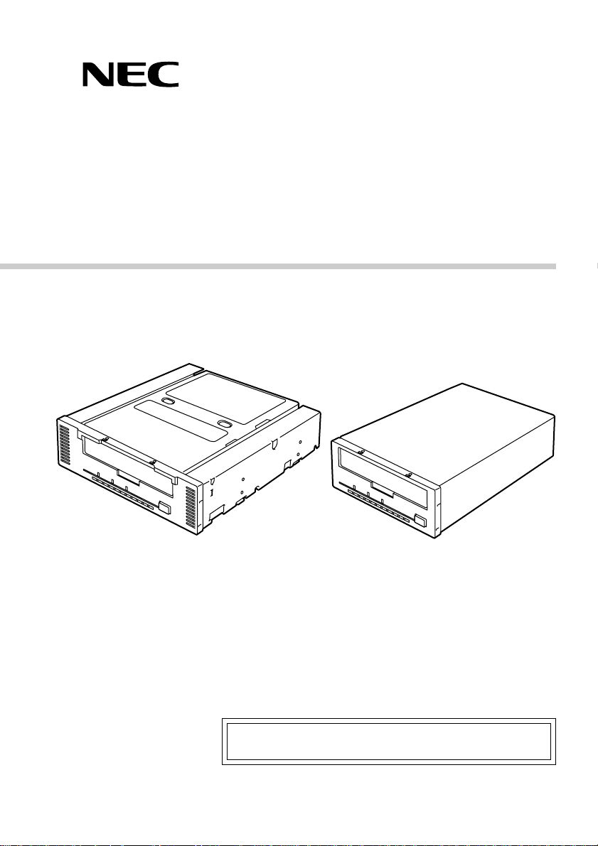
N8551-28F/N8151-44F
Built-In AIT
Instruction Manual
Make sure you read this manual before using the product.
After reading this manual carefully, store it in a safe place.
4-659-559-11(1)
Page 2

Trademarks
Microsoft, the logo of Microsoft and Windows NT are registered trademarks of the Microsoft
Corporation in the United States and other countries.
Advanced Intelligent Tape is a trademark of the Sony Corporation.
The company and product names contained in this manual are trademarks or registered trademarks
of the respective companies.
®
Windows NT 4.0 is an abbreviation of Microsoft
®
version 4.0 and Microsoft
Windows NT® Workstation network operating system version 4.0.
Windows NT® Server network operating system
Windows 2000 is an abbreviation for Microsoft® Windows® 2000 Professional, Microsoft
®
Windows® 2000 Server, and Microsoft® Windows® 2000 Advanced Server.
All names used in the sample applications are fictitious. They have no relation with any product,
party or individual names.
Remarks
(1) Reproduction of this document or portions thereof without prior approval is prohibited.
(2) The information contained in this document is subject to change at any time, without prior
notice.
(3) Reprinting or changing of this document without prior approval of NEC is prohibited.
(4) All efforts have been made to ensure that the contents of this manual are correct; however,
should any doubts arise, or errors or missed entries be detected, NEC would greatly appreciate
it if our dealers are informed about it.
(5) Please note that in no event shall NEC be liable for any damages whatever arising out of the
use of this device, regardless of item (4) above.
© NEC Corporation 2000
ii
Page 3
Keep this User’s Guide at hand for quick reference at anytime necessary.
Safety Consideration - Must Read -
Follow the instructions given in this User’s Guide for proper operations and safe use of the
device.
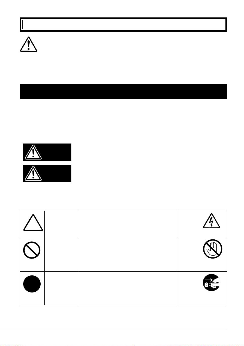
SAFETY INDICATIONS
This User’s Guide describes the device components with possible danger, hazards that
may be caused by ignoring warnings, and preventive actions against such hazards.
Components with possible danger are indicated with a warning label placed on or around
them. In the User’s Guide or warning labels, "WARNING" or "CAUTION" is used to
indicate a degree of danger. These terms are defined as follows:
Failure to heed this sign could result in serious
Warning
Caution
injury or death.
Failure to heed this sign could result in personal
in-jury or damage to properties.
Precautions and notices against hazards are presented with one of the follow-ing three
symbols. The individual symbols are defined as follows:
Attention
Prohibited
Action
Mandatory
Action
This symbol indicates the presence of a
hazard if the instruction is ignored. An
image in the symbol illustrates the
hazard type.
This symbol indicates prohibited
actions. An image in the symbol
illustrates a particular prohibited action.
This symbol indicates mandatory
actions. An image in the symbol
illustrates a mandatory action to avoid a
particular hazard.
(sample)
(Electric shock)
(sample)
(Do not
touch the part)
(sample)
(Disconnect the
power cord)
iii
Page 4
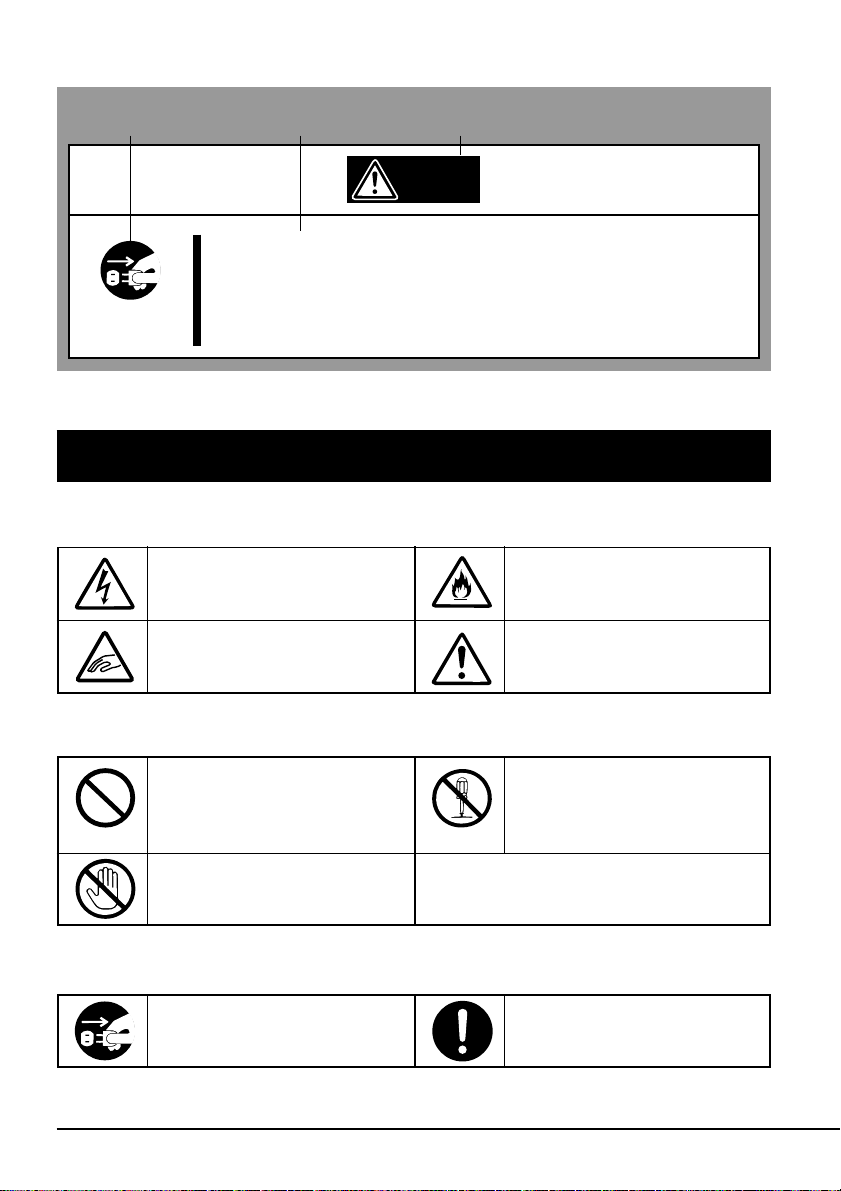
(Sample)
A symbol for
arousing attention
A content of
possible danger
A term indicating a
hazard level
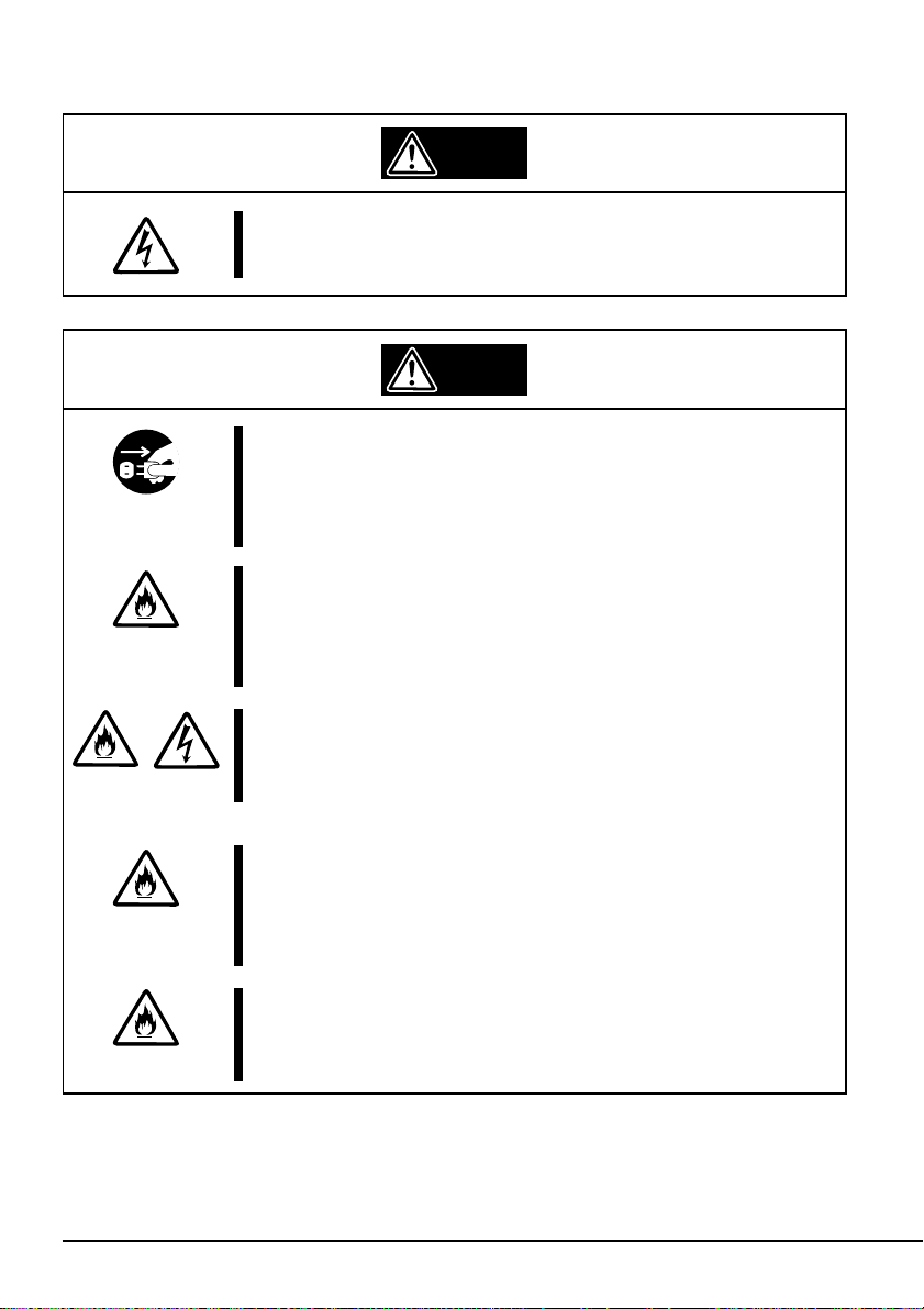
Warning
Do not install the device while the power is turned on.
Unplug the AC power cord from the main power source when
installing/ uninstalling the device to/from basic processing unit
or connect it with the enclosure. Failure to follow this warning
may cause an electric shock.
SYMBOLS USED IN THIS USER’S GUIDE AND WARNING LABELS
Attention
Indicates that improper use
may cause an electric shock.
Indicates that improper use
may cause fingers to be caught.
Indicates that improper use
may cause fumes or fire.
Indicates a general notice or
warning that cannot be
specifically identified.
Prohibited Action
Indicates a general prohibited
action or warning that cannot
be specifically identified.
Do not touch unspecified parts
or units. Otherwise, burns or an
electric shock may be caused.
Mandatory Action
Unplug the power cord.
Otherwise, an electric shock or
fire may be caused.
iv
Do not disassemble, repair, or
modify the device. Otherwise,
an electric shock or fire may be
caused.
Indicates a general mandatory
action or warning that cannot
be specifically identified.
Page 5
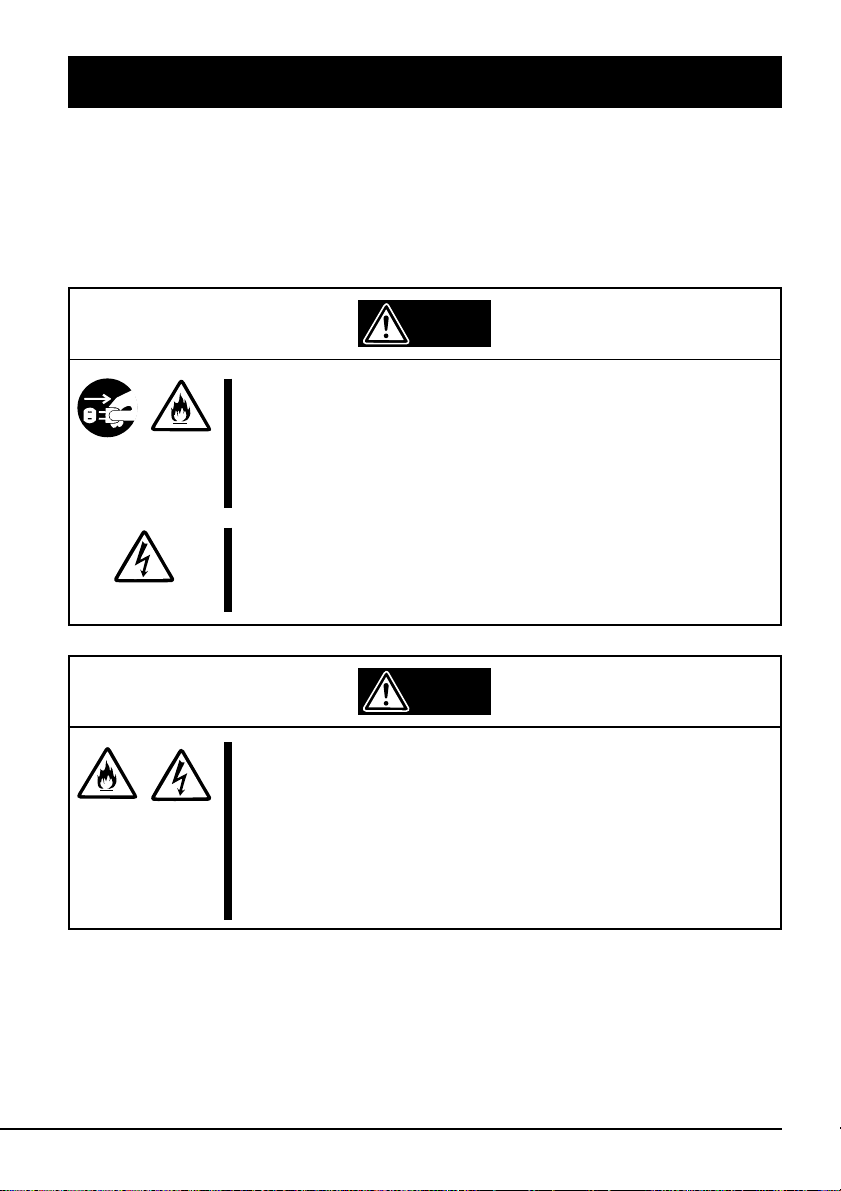
SAFETY NO TES
This section provides several precautions to enable you to use the product safely and
correctly and to prevent injury and property damage. Read this section carefully to ensure
proper and safe use of the product. For symbols, see "SAFETY INDICATIONS" provided
earlier.
General Attention
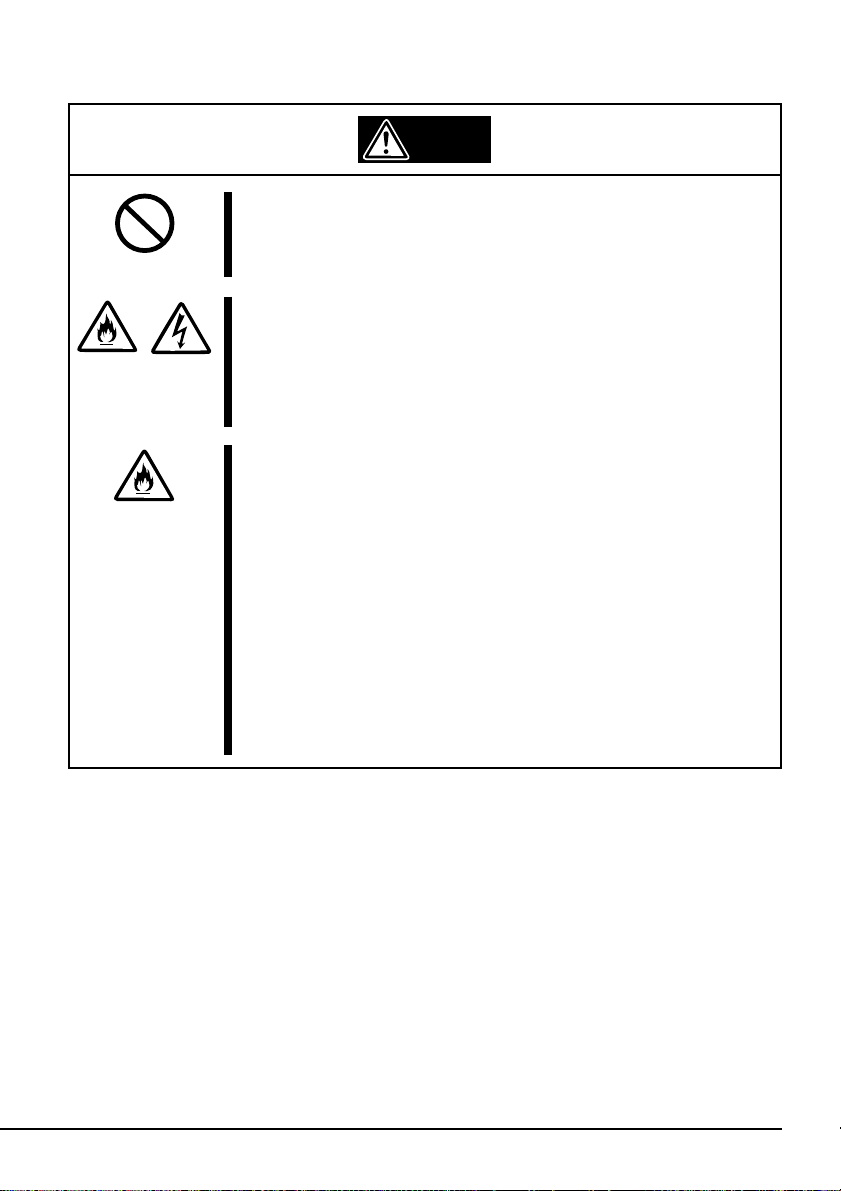
Warning
Do not use the Built-in AIT if any smoke, odor, or noise is
present.
If smoke, odor, or noise is present, immediately turn off the
POWER switch and disconnect the power plug from the outlet,
then contact your sales agent. Using the Built-in AIT in such
conditions may cause a fire.
Keep needles or metal objects away from the Built-in AIT.
Do not insert needles or metal objects into ventilation holes in
the Built-in AIT. Failure to follow this warning may cause an
electric shock.
Caution
Keep water or foreign matter away from the Built-in AIT.
Do not let any kind of liquid (water etc.) or foreign matter
(e.g.,pins or paper clips) enter the Built-in AIT. Failure to follow
this warning may cause an electric shock, a fire, or a failure of
the Built-in AIT. When such things accidentally enter the Built-in
AIT, immediately turn off the power and disconnect the power
plug from the outlet. Do not disassemble the Built-in AIT. Contact
your sales agent.
v
Page 6
Attention to Power or Power Cord
Warning
Do not hold the DC cable with a wet hand.
Do not disconnect/connect the cable while your hands are wet.
Failure to follow this warning may cause an electric shock.
Caution
Do not install the device while the power is turned on.
Unplug the AC power cord from the main power source when
installing/ uninstalling the device to/from basic processing unit or
connect it with the enclosure. Failure to follow this warning may
cause an electric shock.
Insert the DC cable into the outlet as far as it goes.
Heat generation resulting from a halfway inserted DC cable
(imperfect contact) may cause a fire. Heat will also be generated
if condensation is formed on dusty blades of the halfway inserted
cable, increasing the possibility of a fire.
Do not connect the Built-in AIT by unspecified cabling.
Connecting or cabling with DC cable should be done in
accordance with the procedure specified in the User's Guide.
Unspecified connecting or cabling may cause an electric shock
or a fire.
Do not use any damaged power cord.
If the power cord is damaged, immediately replace it with a new
part of same type. Do not repair the damaged section for reuse.
Otherwise, the section repaired with vinyl tape or the like will be
overheated to cause an electric shock or a fire.
Use the authorized cable only.
Use only the specified cable when connecting the Built-in AIT
with a basic processing unit. Use of an unspecified cable or
connection by unspecified cabling may cause a fire.
vi
Page 7
Attention to Installing, Moving, Storing, Connection
Caution
Do not close the ventilation hole.
Do not close the ventilation hole in the front side of the Built-in
AIT. Otherwise, Its internal temperature will rise to cause
malfunctions or a fire.
Do not connect/disconnect the interface cables before
unplugging the power plug.
Before connecting/disconnecting the interface cables, disconnect
the power plug of the main power unit from the outlet. If the
power is off but the power plug is still connected, you may get an
electric shock.
Do not use the unspecified interface cables.
Use only the cable authorized by NEC and locate the device and
connector before connection. Use of an unauthorized cable or
displaced connection may cause a short circuit, resulting in a
fire.
When handling or connecting the interface cables, keep the
notes as follows:
• Do not tread on cables.
• Do not load on the cable.
• Insert the cable connector as far as it goes.
• Do not use damaged cables.
• Do not use damaged connectors.
• Make sure that screwing or the like be done firmly.
vii
Page 8
Attention to Handling or Maintenance
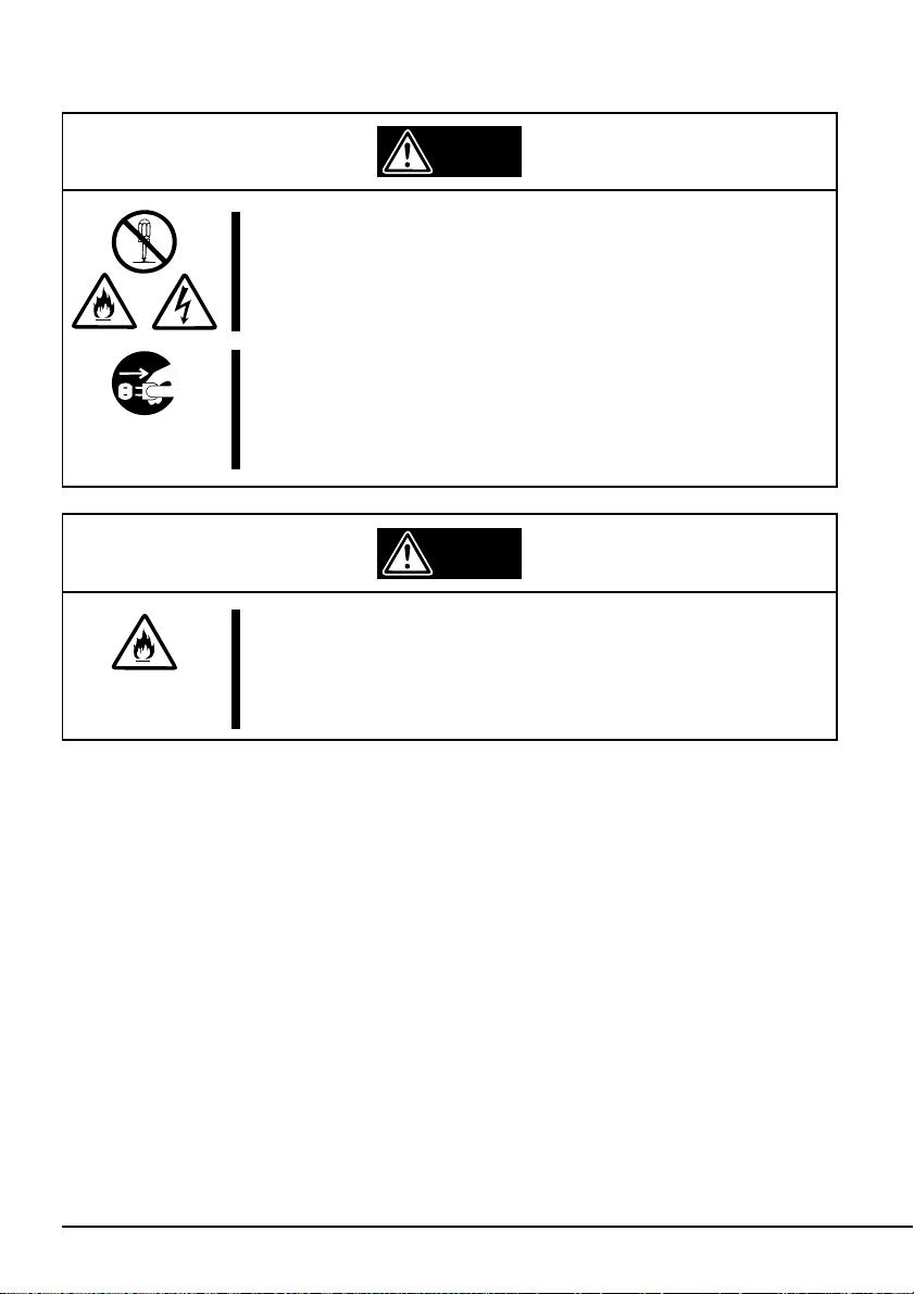
Warning
Do not disassemble, repair, or alter the Built-in AIT.
Never attempt to disassemble, repair, or alter the Built-in AIT on
any occasion other than described in this User's Guide. Failure
to follow this instruction may cause an electric shock or a fire as
well as malfunctions of the Built-in AIT.
Do not handle while the power plug is connected.
Before handling or cleaning the Built-in AIT, disconnect the
power plug of the main power unit from the outlet. If the power is
off but the power plug is still connected, you may get an electric
shock.
Caution
Insert the cables into the connectors as far as it goes.
Heat generation resulting from a halfway inserted cables or
Interface cables (imperfect contact) may cause a fire. Heat will
also be generated if condensation is formed on dusty blades of
the halfway inserted cable, increasing the possibility of a fire.
viii
Page 9
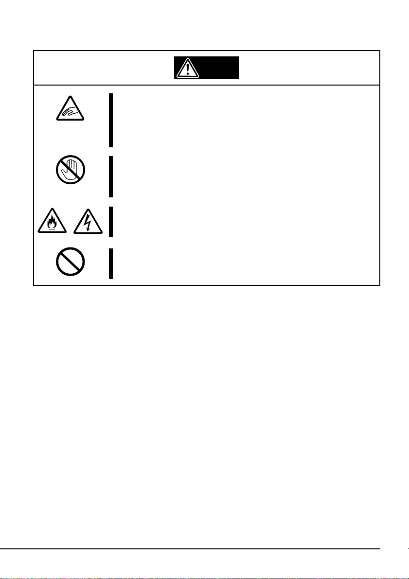
Attention to Operation
Do not insert your hands into the cartridge load
compartment.
Do not insert your hands into the cartridge load compartment.
Otherwise, the fingers will be caught/pinched by the Built-in AIT
to cause an injury.
Do not touch the Built-in AIT when it thunders.
If it starts thundering, do not touch any part of the Built-in AIT.
Failure to follow this warning may cause an electric shock or a
fire.
Keep away pets.
Keep away pets from the Built-in AIT. Insertion their hair or
excrements may cause a fire or an electric shock.
Do not use a cellular phone or a pager
Turn off the power of the cellular phone or a pager. Otherwise,
malfunction may be caused.
Warning
ix
Page 10

For Correct Operation
To operate the N8551-28F/N8151-44F Built-In AIT correctly, observe the following points. For
considerations on handling the AIT data cartridge, refer to the chapter “AIT Data Cartridge”.
• Set the N8551-28F/N8151-44F Built-In AIT’s SCSI ID so that it will not duplicate with SCSI
ID of other SCSI equipment.
→ Otherwise, an operation error will occur.
• When N8551-28F/N8151-44F Built-In AIT is a termination of the SCSI connection, set the
terminal resistance to ON using its DIP switch.
→ Otherwise, an operation error will occur.
• Do not turn off power of the basic processing unit when the BUSY LED on the front of the
Built-In AIT is ON or blinking.
→ This may cause a machine failure or damage of backup data.
• Do not use a portable phone near the Built-In AIT.
→ This may cause a machine failure.
• Do not store the Built-In AIT in a place exposed to direct sunlight.
→ The Built-In AIT may not be able to operate correctly.
• Do not store the Built-In AIT in a place subject to corrosive gas, chemicals or splash of chemi-
cals.
→ A Built-In AIT part may be deformed or damaged and may not be able to operate correctly.
• Do not store the Built-In AIT in a place subject to strong vibrations.
→ This may cause a machine failure.
• Do not put a thing on the Built-In AIT when using or storing it.
→ This may cause a machine failure.
• As the data cartridge set in the Built-In AIT, use our “AIT Data Cartridge (model: AIT2,
AIT1)”.
→ If you use a data cartridge of other manufacturer, a read/write error may occur.
• When cleaning the Built-In AIT, use our “AIT Cleaning Cartridge”.
→ If you use a cleaner of other manufacturer, a machine failure may occur.
x
Page 11

Others
Transfer to a third party
When you transfer (or sell) the N8551-28F/N8151-44F Built-In AIT to a third party, be sure to
include the instruction manual with the driver.
Disposal of consumed parts and equipment
For the disposal of the N8551-28F/N8151-44F Built-In AIT and its cartridge, observe the waste
disposal rules of your local government. For details, contact the local government office.
xi
Page 12

Introduction
Thank you for purchasing the N8551-28F/N8151-44F Built-In AIT.
The Built-In AIT will ensure smooth backup, application and management of your important data.
To maximize the N8551-28F/N8151-44F Built-In AIT functions, please read the instruction
manual carefully before use and fully understand how to handle the device.
xii
Page 13

Organization of the Instruction Manual
The instruction manual function as a guide that enables you to set up and use the N8551-28F/
N8151-44F Built-In AIT correctly. You can refer to this manual whenever you encounter a
question or problem during setup and daily operation.
The instruction manual consists of two chapters: the first covers the considerations on the safe use
of the Built-In AIT (setup, daily operation and maintenance) and the second covers the considerations on the safe use of the AIT data cartridge available on the Built-In AIT (operation and
maintenance).
Order of priority when the N8551-28F/N8151-44F Built-In AIT is used for the first time
When the Built-In AIT is being used first time, refer to the instruction manual in the following
sequence to perform the setup after unpacking the driver.
1. Check the contents in the package. ....................... Package Contents (→P. xv)
2. Learn the operational precaution. ......................... Safety Consideration (→ P. iii)
3. Learn the parts of the Built-In AIT ....................... Part Name and Function (→ P. 2)
4. Set before installation. .......................................... Setup (→ P. 4 to 7)
5. Install the driver in the basic processing unit........ Setup (→ P. 8 to 10)
6. Install the tape driver.* .......................................... Installing the tape driver (→ P. 11 to P. 13)
7. Learn how to handle the cartridge......................... AIT Data Cartridge (→ P. 19)
8. Set the cartridge. ................................................... Handling (→ P. 14)
9. Check the LED indication..................................... Handling (→ P. 16)
10. Clean the Built-In AIT. ......................................... Cleaning (→ P. 17)
* Required only when using Windows NT 4.0 NT backup, and Windows 2000 backup.
For details on data storage methods and settings, such as data save format, refer to
the instruction manual provided with the backup software.
xiii
Page 14

Symbols Used in This Text
The following symbols are used in this text to indicate cautions and notes concerning the operation
of this device. (Refer to the beginning of this document for an explanation of the symbols used for
safety-related cautions.)
Important
Hint
✎
This symbol indicates important information concerning the handling of the
device or the operation of the software.
Indicates useful information and operational help.
xiv
Page 15
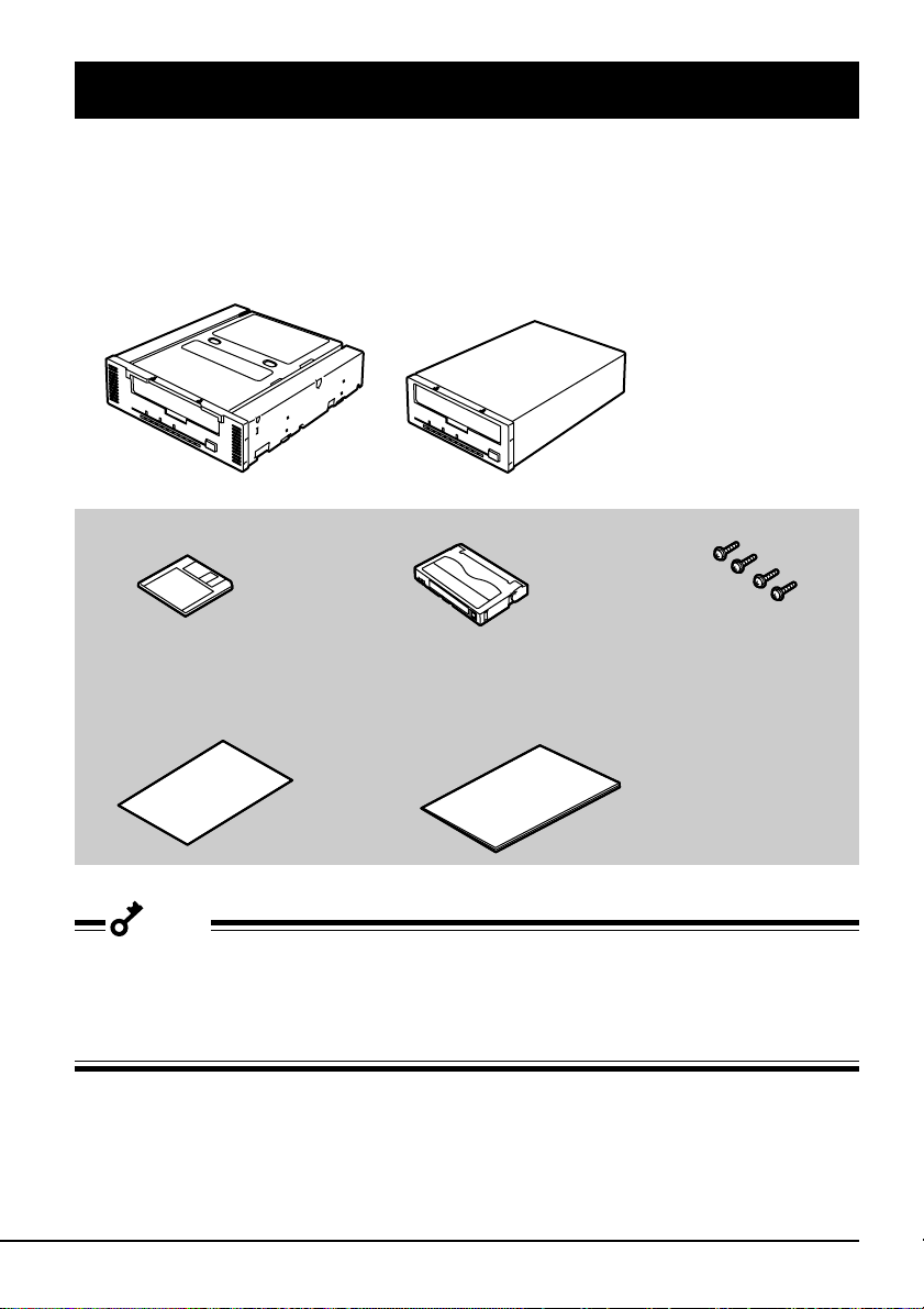
Package Contents
Many accessories are included with the Built-In AIT in the N8551-28F/N8151-44F Built-In AIT.
Verify the packed contents with the part list given below and ensure that all the components and
parts are present. Also, check that each item is undamaged. If a component or part is missing or
damaged, contact your dealer.
N8551-28F Built-In AIT
N8151-44F Built-In AIT
The following accessories are common to the N8551-28F and the N8151-44F.
Floppy disk (Device driver) Cleaning cartridge
Instructions on handling
the AIT unit
Instruction manual (this manual)
Screws (4)
Important
• Locking parts contained in the package or box will be required when removing the Built-In AIT
for transportation. Store them securely.
• Copy a backup from the provided floppy disk. Keep the provided floppy disk as the master disk
and use the backup disk in actual applications.
xv
Page 16

Table of Contents
Trademarks ............................................................... ii
Safety
Consideration
- Must Read -
Built-in AIT
SAFETY INDICATIONS ........................................ iii
SYMBOLS USED IN THIS USER’S GUIDE AND
WARNING LABELS ............................................ iv
SAFETY NOTES ..................................................... v
For Correct Operation.............................................. x
Others ..................................................................... xi
Transfer to a third party ..................................... xi
Disposal of consumed parts and equipment ...... xi
Introduction ............................................................ xii
Organization of the Instruction Manual................. xiii
Order of priority when the N8551-28F/N8151-
44F Built-In AIT is used for the first time.... xiii
Symbols Used in This Text .............................. xiv
Package Contents.................................................... xv
Features..................................................................... 1
Usable Cartridges ..................................................... 1
Part Name and Function ........................................... 2
Front.................................................................... 2
Rear ..................................................................... 2
Bottom ................................................................ 3
Setup ........................................................................ 4
Setting the Built-In AIT
- Setting with the jumper pins - ....................... 4
Setting the Built-In AIT
- Setting with the DIP switch - ........................ 6
Mounting on the basic processing unit ............... 8
Installing the tape device driver........................ 11
Handling ................................................................. 14
Setting the AIT data cartridge........................... 14
Ejecting the AIT data cartridge ......................... 15
LED indication.................................................. 16
Reading/writing data......................................... 16
Cleaning.................................................................. 17
Cleaning the read/write head ............................ 17
Cleaning the Built-In AIT................................. 18
xvi
Page 17

AIT Data Cartridge
Data Cartridge Part Name and Function................. 19
Operation, Storage and Transportation
Requirements........................................................ 20
Label ....................................................................... 20
Label paste position .......................................... 20
Precautions on entry to label............................. 21
Write-protect........................................................... 21
Precautions on Handling......................................... 22
Operational precautions .................................... 22
General precautions .......................................... 22
Usage Inhibition Standard ...................................... 23
Service Life ............................................................ 23
Storing Important Data ........................................... 24
Managing 3-generation Data .................................. 24
Data cartridge storage............................................. 24
xvii
Page 18

Page 19

Built-in AIT
This chapter explains setup, installation and daily operation of the N8551-28F/N8151-44F Built-In
AIT.
Features
This unit has the following features:
• You can record large amounts of data on the AIT1 and AIT2 data cartridges using AIT (Advanced Intelligent Tape) format.
• When the data compression function is used, an AIT2 (tape length: 230 m) data cartridge can
store 50 to 100 GB of data, an AIT1 (tape length: 230 m) data cartridge can store 35 to 70 GB of
data, and an AIT1 (tape length: 170 m) data cartridge can store 25 to 50 GB of data.
• The basic processing unit automatically determines whether data recorded on the AIT data
cartridges is compressed. It can also read data recorded on AIT data cartridges with conventional AIT drives.
*1
The compression rate for recorded data may differ depending on the user environment and
the type of data.
(When using an average compression rate of 2.)
Usable Cartridges
Please use Sony AIT data cartridges (AIT2 (tape length: 230 m), or AIT1 (tape length: 230 m),
(tape length: 170 m)) with this unit. Using other types of AIT data cartridges may cause read and
write errors.
Built-in AIT 1
Page 20

Part Name and Function
The Built-In AIT and magazine have the following parts and functions.
Important
The names and functions of each part of the N8551-28F and the N8151-44F and the setup
methods are identical. (Hereafter, the N8151-28F is used for the illustrations in this manual.)
Front
➀ Data cartridge slot
➀
➅ ➃ ➂ ➁
➄
A slot in which the AIT cartridge is set
(→ P. 14)
➁ Ventilation holes
(The N8151-44F does not have
ventilation holes.)
➂ EJECT button
Press this button when ejecting the
AIT cartridge from the Built-In AIT.
(→ P. 15)
➃ STATUS LED
An LED which shows the Built-In AIT
status. (→ P. 16)
➄ TAPE LED
An LED which shows the status of the
AIT data cartridge (→ P. 16)
➅ BUSY LED
An LED which shows the data
communication status (→ P. 16)
Rear
2 Built-in AIT
➀
➀ Fan
➁ Power connector
Connect the Built-In AIT’s built-in
power cable. (→ P. 9 )
➂ Jumper pin
Pins which set the Built-In AIT
(→ P. 4)
➃ SCSI connector
Connect the Built-In AIT’s built-in
SCSI cable. ( → P. 9 )
➁➃
➂
Page 21

Bottom
12345678
➀ DIP switch
Switches which set the Built-In AIT
ON
(→ P. 6 )
➀
Built-in AIT 3
Page 22

Setup
The procedure up to installation of the Built-In AIT to the “basic processing unit” is explained in
the following.
Setting the Built-In AIT - Setting with the jumper pins -
You can change the following settings with the jumper pins on the rear of the Built-In AIT.
• SCSI ID (factory-set to “ID4”)
• Parity function (factory-set to “Enabled”)
SCSI ID (pin 0 to 3 from right)
Unused (NC)
Parity (PD)
Hint
✎
Hint
✎
“With strap” means a status that the straps are attached to two pins. “Without strap” means a
status that no strap is attached to either pin or it is attached to one of two pins.
“Without strap” means that one strap is
attached to one of the two pins, or that
the strap has been removed altogether .
If you remove the strap, make sure you
store it in a safe place.
4 Built-in AIT
Page 23

Setting SCSI ID
Set SCSI ID which is used by the Built-In AIT. Use four jumper pins, pin 0 to pin 3, on the rear of
the Built-In AIT.
Pin 3 (Factory-set to “Without strap”)
Pin 2 (Factory-set to “With strap”)
Pin 1 (Factory-set to “Without strap”)
Pin 0 (Factory-set to “Without strap”)
Important
Check that the Built-In AIT’s SCSI ID is not duplicated with SCSI ID of other SCSI device.
SCSI ID Pin 3 Pin 2 Pin 1 Pin0
0 ✕✕✕✕
1 ✕✕✕❍
2 ✕✕❍✕
3 ✕✕❍❍
*1
4
5 ✕❍✕❍
6 ✕❍❍✕
*2
7
8 ❍✕✕✕
9 ❍✕✕❍
10 ❍✕❍✕
11 ❍✕❍❍
12 ❍❍✕✕
13 ❍❍✕❍
14 ❍❍❍✕
15 ❍❍❍❍
✕❍✕✕
✕❍❍❍
❍ : W ith strap
✕ : Without strap
*1
: Factory-set value
*2
: Do not set SCSI ID to ID7.
Built-in AIT 5
Page 24

Setting the parity function
Set the parity function using the leftmost jumper pin on the rear of the Built-In AIT.
The parity function is “Enabled” when setting “Without strap” (factory-set value). The parity
function is “Disabled” when setting “With strap”.
PD (Factory-set to “Without strap”)
Important
To improve reliability, set the parity function “Enabled” (Without strap).
Setting the Built-In AIT - Setting with the DIP switch -
The DIP switch on the bottom of the Built-In AIT enables you to change the following settings.
• Terminator Power (Terminator power supply) (Factory-set to ON)
• DC Control (1) (Data compression setting) (Factory-set to ON)
• DC Control (2) (Data compression setting) (Factory-set to OFF)
6 Built-in AIT
ON
12345678
Switches 1 to 4: Unused
Switch 5: Terminator Power
Switch 6: Unused
Switch 7: DC Control (1)
Switch 8: DC Control (2)
Page 25

Setting terminator power - Terminator Power -
Set whether terminator power is supplied to the SCSI bus or not.
Use Switch 5. Setting Switch 5 to ON (factory-set to ON) will
supply terminator power; setting Switch 5 to OFF will not supply
terminator power.
Important
When this unit is installed in the N8541-28F/N8141-28F device expansion unit, set this switch to
OFF if you want to use the slaved power control feature.
12345678
Setting data compression - DC Control (1) -
Set whether the Built-In AIT’s data compression function is enabled
or disabled.
Use Switch 7. Setting Switch 7 to ON (factory-set to ON) will
enable the data compression function; setting Switch 7 to OFF will
12345678
disable the terminator data compression function.
Setting data compression - DC Control (2) -
Set whether control of data compression from the backup software
is enabled or disabled.
Use Switch 8. Setting Switch 8 to ON will disable control of data
compression from the backup application; setting Switch 8 to OFF
(factory-set to OFF) will enable control of data compression from
the backup software.
12345678
ON
ON
ON
Built-in AIT 7
Page 26

Mounting on the basic processing unit
Caution
Turn off the power before installing or removing the device
Always be sure to turn off the main power and unplug the power cord from the
AC outlet before installing/removing this device or connecting any cables.
There is a risk of electric shock if this device in installed or removed or if any
cables are connected while the power cord is still plugged into an AC outlet.
The procedure for installing the drive in a server is as follows.
Hint
✎
Some servers require the rails to be used. For details on how to install the rails, refer to the
server's operating manual.
1 Install the N8551-28F/8151-44F Built-
In AIT as shown below.
Install in
either bay
8 Built-in AIT
Page 27

Important
• When using the rails, adjust their
mounting positions so that the front
cover of this device is aligned with
the front covers of the other
standard components (such as the
Use screws to secure
the upper rail.
Front cover
Rails
CD-ROM).
• Always use the screws that are provided with this device. The screws that
are provided with this device are millimeter screws (length: 5.0 mm; length
below washer: 3.5 mm). Using screws that are longer than the screws that
are provided with this device could result in damage to the device.
2 Connect the cables to the drive as
shown below.
3.5 mm
millimeter screw
DC power cable
(unused power
supply connector in
the computer)
SCSI interface cable
Important
• Confirm the SCSI ID and other settings before installation.
• The factory default setting of the SCSI ID is 4. Make sure this ID is not used by any other
device in the system.
• This unit does not have a built-in terminator. When connecting this unit to the last terminal of
the SCSI bus terminal, attach a terminator to the end of the SCSI cable.
3 Attach the cover to the basic processing unit. Plug the power cable to the outlet.
4 Turn on the basic processing unit.
Built-in AIT 9
Page 28

5 When the SCSI bus can be set on the side of the basic processing unit, set the following on the
Built-In AIT .
• Transfer rate : 40 MByte/second (max., synchronous)
• Data bus width : 16 bits (Ultra Wide SCSI, LVD/SE)
• DISCONNECT/RECONNECT function : Enable
For details, see the instruction manual provided with the basic processing unit.
Important
Set the maximum transfer rates as follows according to the number of devices connected to the
bus and the SCSI cable length.
SCSI ID
Ultra Wide SCSI 40 16 3 (-) 4
Ultra Wide SCSI 40 16 1.5 (-) 8
Ultra Wide SCSI 40 16 - (3) 16
Fast Wide SCSI 20 16 3 (3) 16
Wide SCSI 10 16 6 (3) 8
Maximum transfer Data bus Maximum cable
rate (Mbyte/s) width (bit) length (m) of devices
Single-ended (SCSI host +
(LVD*) number of
Maximum number
devices)
* When the SCSI host and all devices connected to the same bus are LVD-compatible.
10 Built-in AIT
Page 29

Installing the tape device driver
Install the tape device driver only when you want to use the Windows NT 4.0 backup (management
tool), or Windows 2000 backup (system tool).
Install the tape device driver in the basic processing unit. As the driver, use the provided floppy
disk. Prepare it beforehand.
For Windows NT 4.0 Users
1 Click [Start] button. Point [Setting] and click [Control Panel].
[Control Panel] dialog box appears.
2 Click [Tape Device] in [Control Panel].
[Tape Device] dialog box appears.
3 Click [Driver] tab.
4 Click [Add] button.
[Install Driver] dialog box appears.
5 Click the [Use Disk] button.
The [Install from floppy disk] dialog box is displayed.
6 Confirm that “A:\” is specified for the distributed file copy source (C):, and click the [Browse]
button.
The [Browse] dialog box appears.
7 Point to “WinNT4.0”, then click the [Open] button.
[NT4ait.inf] is displayed in the [Search Files] dialog box.
8 Confirm that “NT4ait.inf” is specified as the file name, then click the [Open] button.
9 Confirm that “A:\WinNT4.0” is specified for [Distributed file copy source (C)] and click the
[OK] button.
The [Installing Drivers] dialog box appears.
10 Click “Sony AIT Tape Drive (NT 4.0)” displayed in the [Tape Device] box, and click the [OK]
button.
The driver files are copied, then installation is completed.
Built-in AIT 11
Page 30

11 Restart the system.
Important
When using Windows NT backup, do not install any other backup software. If any other backup
software is installed, make sure you uninstall it. Further, when using backup software other than
Windows NT backup, make sure you delete “Sony AIT Tape Drive (NT 4.0)”.
Hint
✎
The tape device driver installed after restarting the system is enabled.
For Windows 2000 Users
1 Click the [Start] button, then point to [Settings] and click [Control Panel]. Then click [System].
The [System Properties] dialog box appears.
2 Click the [Hardware] tab, then click the [Device Manager] button.
The [Device Manager] dialog box appears.
3 Confirm that [SONY SDX-500C SCSI Sequential Device] is displayed under [Other devices],
and double click [SONY SDX-500C SCSI Sequential Device].
The [SONY SDX-500C SCSI Sequential Device Properties] dialog box is displayed.
4 Click the [Driver] tab, and click the [Update Driver] button.
The [Upgrade Device Driver Wizard] appears.
5 Click the [Next] button.
The [Install Hardware Device Drivers] screen appears.
6 Select [Search for a suitable driver for my device (recommended)], and click the [Next] button.
The [Locate Driver Files] screen appears.
Insert the floppy disk provided.
7 Place a checkmark in the [Floppy disk drives] checkbox, and click the [Next] button.
The basic processing unit starts searching for driver files.
12 Built-in AIT
Page 31

8 Confirm that [This wizard upgrades drivers for the following hardware device: SONY SDX-
500C SCSI Sequential Device] is displayed, and click the [Next] button.
The [Insert Disk] dialog box appears.
9 Click the [OK] button.
The driver is copied, then the [Files needs] dialog box appears.
10 Confirm that “A” is specified as the file copy source, and click the [Browse] button. Then
select sonyait2.sys, and click the [Open] button.
The screen returns to the [Files needs] dialog box.
11 Click the [OK] button.
The [Completing the Upgrade Device Driver Wizard] screen is displayed.
12 Click the [Finish] button.
Built-in AIT 13
Page 32

Handling
The following explains how to handle the N8551-28F/N8151-44F Built-In AIT.
Setting the AIT data cartridge
Important
• As the data cartridge to be set in the magazine, use our “AIT Data Cartridge (model: AIT2,
AIT1)”. If you use a data cartridge of other manufacturer, a read/write error may occur.
• While setting the data cartridge, do not turn off the basic processing unit. This may cause a
malfunction or damage data.
1 Turn on the basic processing unit.
Check that the driver’s STATUS
LED, BUSY LED and TAPE LED
go off.
2 Set the AIT data cartridge orienta-
tion as shown below and insert it
into the data cartridge slot.
By inserting the data cartridge to the
extent, it is automatically set in the
driver and the TAPE LED lights.
Important
When write-protect is enabled using the AIT data cartridge
write-protect plug so that you cannot write data in the data
cartridge, the STATUS LED lights.
STATUS LED
14 Built-in AIT
Write-protect plug (Sliding it up
write-protects the cartridge.)
(→ 21 page)
Page 33

Ejecting the AIT data cartridge
Check that the BUSY LED goes off.
Then, press the EJECT button. The
Built-In AIT starts rewinding the tape
(this may take a few minutes).
When the tape is completely rewound,
the data cartridge is automatically
ejected from the Built-In AIT.
Remove the data cartridge from the slot.
Important
• When the BUSY LED lights or is blinking, do not turn off the basic processing unit. This may
cause a malfunction or damage data.
• To avoid malfunction, do not transport this unit with the data cartridge installed.
Built-in AIT 15
Page 34

LED indication
Four LED on the Built-In AIT’s front side signal the status of the driver and the AIT data cartridge.
LED name Indication status Description
POWER LED OFF The Built-In AIT power supply is off.
ON The Built-In AIT power supply is on.
BUSY LED OFF –
ON Transmitting or receiving the data now
Blink The data is normally read/written from/to the
data cartridge set in the Built-In AIT.
TAPE LED OFF The data cartridge is not set.
ON The data cartridge is set.
Blink (at a given interval) The data cartridge is being set or ejected.
Blink (repeating a long ON
and a short ON)
STATUS LED OFF The data cartridge set in the Built-In AIT is
ON The data cartridge set in the Built-In AIT is
Blink (repeating a long ON
and a short OFF)
Blink (at a given interval) During the head cleaning, the cleaning
Blink (repeating a short ON
(once or twice) and a long ON)
The data cartridge set in the Built-In AIT is
deteriorated.
ready to write data.
not enabled to write data (write-protected).
The Built-In AIT head needs cleaning.
cartridge tape comes to the end.
The driver is broken.
Reading/writing data
To read/write the data from/to the AIT data cartridge, see the instruction manual provided with the
backup application.
16 Built-in AIT
Page 35

Cleaning
To keep the driver in the best condition, regular cleaning is required.
Cleaning the read/write head
When the STATUS LED is blinking (repeating a long ON and a short ON), clean the read/write
head within the driver.
Set the provided cleaning cartridge in the driver, following the procedure described in “Handling”
in “Setting the AIT Data Cartridge”.
When set in the Built-In AIT, the cleaning cartridge automatically starts cleaning the head.
After cleaning, the cleaning cartridge is automatically ejected (which requires about 35 seconds
after starting cleaning). Remove the cleaning cartridge.
Important
• Use our “AIT Cleaning Cartridge” to clean
the Built-In AIT. If you use a cleaner of other
manufacturer, a machine failure may be
caused.
• Do not touch the cleaning cartridge tape
surface or rewind the tape.
• You can use the cleaning cartridge for about
70 times. When the STATUS LED blinks (at a
given interval) during cleaning, the cleaning
cartridge tape comes to the end. (Eject the
cleaning cartridge tape and check that all the
tapes are wound around the right reel.)
Purchase a new cleaning cartridge tape.
Hint
✎
Before using the AIT data cartridges, you should clean the read/write head using the cleaning
cartridge once a week. (The cleaning frequency varies depending on the operating environment
(generation of dust and dirt) and the operation frequency. When using the Built-In AIT every day in
a typical office, a weekly cleaning is recommended.)
Built-in AIT 17
Page 36

Cleaning the Built-In AIT
If the Built-In AIT looks dirty, gently wipe its surface with soft cloth moistened with water or
detergent.
Important
Do not clean the Built-In AIT using chemicals such as benzine or thinner (volatile chemicals),
which may cause the unit to be deformed or discolored. For the same reason, do not spray
insecticide. If a chemical adheres to the driver surface, immediately wipe it with soft cloth
moistened with water.
18 Built-in AIT
Page 37

AIT Data Cartridge
This chapter explains how to handle the AIT data cartridge.
Data Cartridge Part Name and Function
Label paste position
Label paste position
Write-protect plug
Handle for insertion/ejection
(The same one is provided on
the opposite site.)
AIT Data Cartridge 19
Page 38

Operation, Storage and Transportation Requirements
■ Operation requirement
Temperature : 5 to 45 °C
Humidity : 20 to 80 % (The maximum temperature of wet bulb is 26 °C.)
Shelf time : If an AIT data cartridge is exposed to an environment other than
the operating or storage environment, expose it to the operating
environment for a longer time than the period when it is exposed to
other environment (for 8 hours at maximum) before use. The
temperature gradient is 10 °C/hour.
■ Storage requirement
Temperature : 5 to 32 °C
Humidity : 20 to 60 % (The maximum temperature of wet bulb is 26 °C.)
Storage condition : Store an AIT data cartridge in a protective case with cover. You
can place the case horizontally or vertically.
■ Transportation requirement
Temperature : -40 to 45 °C
Humidity : 5 to 80 % (The maximum temperature of wet bulb is 26 °C.)
Temperature gradient : 10 °C/hour
Transportation condition : Store an AIT data cartridge in a protective case. During transporta-
tion, pack the case so that force will not apply to the AIT data
cartridge.
Label
It is recommended that you should affix a label to each AIT cartridge to associate the AIT data
cartridge with the backup data for easier identification.
Label paste position
20 AIT Data Cartridge
Page 39

Precautions on entry to label
• To represent the data contained in the AIT data cartridge, use a label which can be easily
replaced and no adhesion trace is left.
• To change the label indication, do not erase it with an eraser but peel the old label and paste a
new one. (The INDEX labels are provided with the AIT data cartridge.)
• Pasting the label in the position specified in the previous section. To replace the label, peel the
old label and paste a new one.
• When using a label other than the specified INDEX label, its size should be the same as the
specified label.
• Enter the date when starting to use the cartridge in the provided INDEX label. It will help you
check the AIT data cartridge service life.
Write-protect
By setting the write-protect plug as
shown at right, the tape data can be
protected.
When you do not want to erase the
written data, set the plug to the “SAFE”
position (write disable). To enable write
to the tape, set the plug to the “REC”
position (write enable).
AIT2
Write enable Write disable
AIT1
Write enable Write disable
Write-protect plug
Write-protect plug
AIT Data Cartridge 21
Page 40

Precautions on Handling
Operational precautions
Before use
• If the AIT data cartridge is damaged, deformed or bent, do not use it.
• If the AIT data cartridge is exposed to an environment other than the operating or storage
environment, expose it to the operating environment for a longer time than the period when it is
exposed to other environment (for 8 hours at maximum) before use. If temperature is greatly
different between the storage site and the operating site, do not rush the cartridge into the
operating environment. Leave the AIT data cartridge in temperature of the operating site with
temperature gradient set to 10 °C/hour.
Mounting to the Built-In AIT
Set the cartridges as explained in “Setting the AIT data cartridge”. Close the empty protective case
firmly and store it in a place free of dust and dirt.
After use
Be sure to put the AIT data cartridge that you used in the protective case and store it in a place free
of dust and dirt. You can place it horizontally or vertically.
General precautions
• Do not touch a tape by hands. Do not
open or close the tape cover.
• Do not bring a substance which generate
magnetic close to the cartridge.
• Do not place the cartridge in a place
subject to direct sunlight or a place near a
heater.
• Do not apply strong shock.
• Avoid handling the cartridge while eating
or drinking. Take due consideration not
to adhere thinner or alcohol to the
cartridge.
Tape surface
Tape cover
• Insert the cartridge to the Built-In AIT gently and carefully.
22 AIT Data Cartridge
Page 41

Usage Inhibition Standard
If an AIT data cartridge that you are using is in the case below, you must replace it.
• When the AIT data cartridge is given a strong shock, for example, when falling, and damaged.
• When the recording surface is contaminated with liquid, such as soft drink, coffee and tea,
detergent, metal chips or cigarette ash.
Important
If you insert an AIT data cartridge in such a condition into the Built-In AIT, the read/write head or
the driver itself may be damaged or contaminated, causing a machine failure.
Also, if you insert a new AIT data cartridge into the Built-In AIT whose head is contaminated or
scratched and you do not know about it, the AIT data cartridge may be contaminated or damaged.
In this way, damage is expanding.
Service Life
The service life of the AIT data cartridge varies greatly depending on temperature and humidity in
the operating/storage environment, dust and dirt, and head abrasion condition.
You can judge its service life in the following sequence.
• Assign a management number to a new AIT data cartridge. Enter the number in the AIT data
cartridge label.
• Create the AIT data cartridge management book. Record the date when each AIT data cartridge
is used and estimate how many years and how often each cartridge is used.
• Examine the AIT data cartridge management book and index label regularly. Discard the
cartridges having low reliability, for example, those which generate write/read errors.
The tape magnetic layer is composed of chemicals and it becomes deteriorated as the time elapses.
Although the tape service life, which is determined by this deterioration, varies greatly depending
on the tape storage environment (humidity, temperature), the tape is generally serviceable for about
3 years since you purchase it.
AIT Data Cartridge 23
Page 42

Storing Important Data
When storing important data or programs, it is strongly recommended that you should prepare and
store the master tape and copy (backup) tape just in case.
Further, we recommend that you verify backup software when saving, and check saved data. For
details on verification, refer to the instruction manual for the backup software you are using.
By doing this, if one of the tapes causes a read error due to dust or dirt, you can recover the data
from the other tape. Thus, you can prevent loss of important data and programs.
Managing 3-generation Data
To store the data on the disk, you should manage the data in the three generations.
To manage the 3-generation data, use three tapes (A, B, C). On the first day, store the data on the
disk in tape A. On the second day, store the data in tape B. On the third day, store the data in tape
C.
This method allows you to protect your important data. For example, if tape C generates a read
error, you can use tape B to recover the data. If tape B generates a read error, you can use tape A
to recover the data.
Data cartridge storage
Always store data cartridges in a clean location under the specified storage conditions.
Enabling the write-protect feature is recommended when storing data cartridges.
When storing data cartridges for an extended period of time, data should be read periodically in
order to ensure that restoration from backup data is possible at all times.
Storing data cartridges in a different location from the system is recommended. If both master and
spare data cartridges are kept, storing each in a different location is recommended.
24 AIT Data Cartridge
Page 43

Specification
The N8551-28F/N8151-44F Built-In AIT has the following specification:
■ Performance
Memory capacity 50 Gbyte (In the compression mode: 100 Gbyte) when
using AIT2 Data Cartridge: tape length 230 m
35 Gbyte (In the compression mode: 70 Gbyte) when using
AIT1 Data Cartridge: tape length 230 m
25 Gbyte (In the compression mode: 50 Gbyte) when using
AIT1 Data Cartridge: tape length 170 m
The value in the compression mode is obtained when the
compression efficiency is X2.
The compression efficiency varies with the data pattern.
-17
Bit error code 10
Data transfer speed (TAPE) 6 Mbyte/second (in the non-compression mode)
Burst data transfer speed (SCSI) 40 Mbyte/second (max, synchronous)
Initialize time Less than 5 seconds
Load time Less than 14 seconds
Unload time Less than 20 seconds
Rewind time Less than 105 seconds
■ Environmental requirement
During operation Temperature: 5 °C to 35 °C
During non-operation Temperature: -40 °C to 70 °C
or less
Humidity: 20% to 80% (no dew condensation allowed)
Highest dry bulb temperature: 26 °C
Humidity: 10% to 90% (no dew condensation allowed)
■ Power supply specification
Voltage 5V±5% 12V±10%
Current (Typ.) 1.5A 0.4A
Current (Max.) 2.5A 1.2A
Specification 25
Page 44

■ Dimensions, weight
N8551-28F
41.2mm
149.0mm 162.0mm
N8151-44F
41.2mm
101.6mm 162.0mm
Weight 1.0 kg
Weight 0.75 kg
26 Specification
Page 45

Customer’s Application Sheet
Use this sheet as a note in which the information required for maintenance and management of the
N8551-28F/N8151-44F Built-In AIT.
Item Record
Basic processing unit model
name
Operating system (OS) (name,
version, service pack/batch
application)
Backup software (name,
version service pack/batch
application)
SCSI bus configuration (SCSI
ID/device on the same bus)
Built-In AIT installation
environment
Built-In AIT installation
environment (temperature,
humidity, dust)
Cartridge type (manufacturer,
EF model code)
Cleaning cartridge type
Cleaning cartridge usage
(method of managing cleaning
frequency, operation frequency
and starting month)
Cartridge usage (method of
managing cleaning frequency,
operation frequency and
starting month)
Cartridge management
Customer’s Application Sheet 27
Page 46

Page 47

N8551-28F/N8151-44F
Built-In AIT Operating Manual
First Edition, November 2000
Second Edition, August 2001
NEC Corporation
5-7-1 Shiba, Minato-ku, Tokyo
Tel. (03) 3454-1111 (Main switchboard)
©2000 NEC Corporation
No copying or modifying without permission of NEC Corporation.
The contents of this document may be changed without notice.
Page 48

Printed in Japan
Printed on recycled paper.
 Loading...