

Page 1
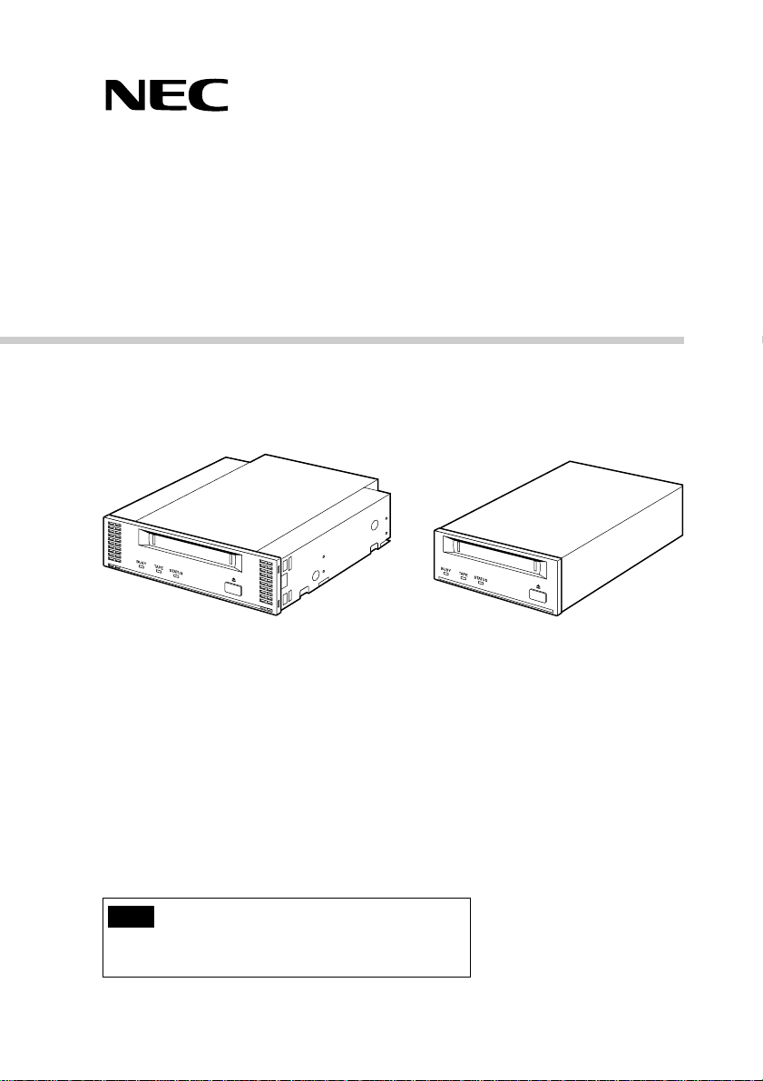
N8551-26F/N8151-43F
Built-In DAT Users Guide
Note
• Please read this guide before using the drive.
• After reading it, keep this guide for future reference.
Page 2

Trademarks
Microsoft, the logo of Microsoft and Windows NT are registered trademarks of the Microsoft
Corporation in the United States and other countries.
Digital Data Storage is a trademark of the Sony Corporation.
The company and product names contained in this manual are trademarks or registered trademarks
of the respective companies.
®
Windows NT 4.0 is an abbreviation of Microsoft
®
version 4.0 and Microsoft
Windows NT® Workstation network operating system version 4.0.
Windows NT® Server network operating system
Windows 2000 is an abbreviation for Microsoft® Windows® 2000 Professional, Microsoft
®
Windows® 2000 Server, and Microsoft® Windows® 2000 Advanced Server.
All names used in the sample applications are fictitious. They have no relation with any product,
party or individual names.
Remarks
(1) Reproduction of this document or portions thereof without prior approval is prohibited.
(2) The information contained in this document is subject to change at any time, without prior
notice.
(3) Reprinting or changing of this document without prior approval of NEC is prohibited.
(4) All efforts have been made to ensure that the contents of this manual are correct; however,
should any doubts arise, or errors or missed entries be detected, NEC would greatly appreciate
it if our dealers are informed about it.
(5) Please note that in no event shall NEC be liable for any damages whatever arising out of the
use of this device, regardless of item (4) above.
© NEC Corporation 2000
ii
Page 3
Keep this User’s Guide at hand for quick reference at anytime necessary.
Safety Consideration - Must Read -
Follow the instructions given in this User’s Guide for proper operations and safe use of the
device.
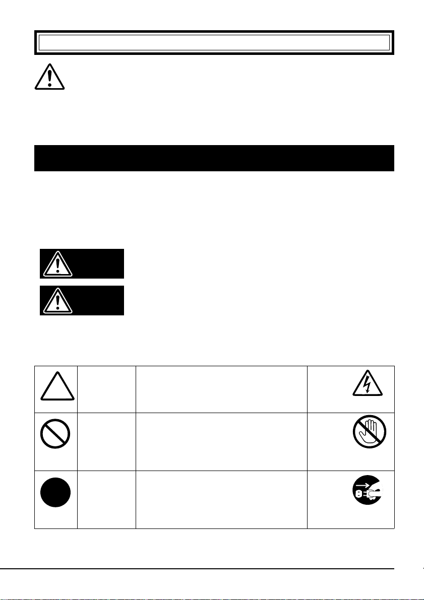
SAFETY INDICATIONS
This User’s Guide describes the device components with possible danger, hazards that
may be caused by ignoring warnings, and preventive actions against such hazards.
Components with possible danger are indicated with a warning label placed on or around
them. In the User’s Guide or warning labels, "WARNING" or "CAUTION" is used to
indicate a degree of danger. These terms are defined as follows:
Failure to heed this sign could result in serious
Warning
Caution
injury or death.
Failure to heed this sign could result in personal
in-jury or damage to properties.
Precautions and notices against hazards are presented with one of the follow-ing three
symbols. The individual symbols are defined as follows:
Attention
Prohibited
Action
Mandatory
Action
This symbol indicates the presence of a
hazard if the instruction is ignored. An
image in the symbol illustrates the
hazard type.
This symbol indicates prohibited
actions. An image in the symbol
illustrates a particular prohibited action.
This symbol indicates mandatory
actions. An image in the symbol
illustrates a mandatory action to avoid a
particular hazard.
(sample)
(Electric shock)
(sample)
(Do not
touch the part)
(sample)
(Disconnect the
power cord)
iii
Page 4
(Sample)
A symbol for
arousing attention
A content of
possible danger
A term indicating a
hazard level
Warning
Do not install the device while the power is turned on.
Unplug the AC power cord from the main power source when
installing/ uninstalling the device to/from basic processing unit
or connect it with the enclosure. Failure to follow this warning
may cause an electric shock.
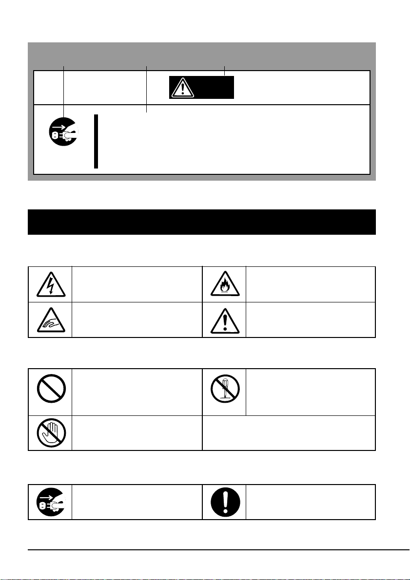
SYMBOLS USED IN THIS USER’S GUIDE AND WARNING LABELS
Attention
Indicates that improper use
may cause an electric shock.
Indicates that improper use
may cause fingers to be caught.
Indicates that improper use
may cause fumes or fire.
Indicates a general notice or
warning that cannot be
specifically identified.
Prohibited Action
Indicates a general prohibited
action or warning that cannot
be specifically identified.
Do not touch unspecified parts
or units. Otherwise, burns or an
electric shock may be caused.
Mandatory Action
Unplug the power cord.
Otherwise, an electric shock or
fire may be caused.
iv
Do not disassemble, repair, or
modify the device. Otherwise,
an electric shock or fire may be
caused.
Indicates a general mandatory
action or warning that cannot
be specifically identified.
Page 5
SAFETY NO TES
This section provides several precautions to enable you to use the product safely and
correctly and to prevent injury and property damage. Read this section carefully to ensure
proper and safe use of the product. For symbols, see "SAFETY INDICATIONS" provided
earlier.
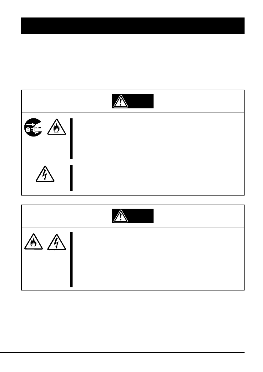
General Attention
Warning
Do not use the Built-in DAT if any smoke, odor, or noise is
present.
If smoke, odor, or noise is present, immediately turn off the
POWER switch and disconnect the power plug from the outlet,
then contact your sales agent. Using the Built-in DAT in such
conditions may cause a fire.
Keep needles or metal objects away from the Built-in DAT.
Do not insert needles or metal objects into ventilation holes in
the Built-in DAT. Failure to follow this warning may cause an
electric shock.
Caution
Keep water or foreign matter away from the Built-in DAT.
Do not let any kind of liquid (water etc.) or foreign matter
(e.g.,pins or paper clips) enter the Built-in DAT. Failure to follow
this warning may cause an electric shock, a fire, or a failure of
the Built-in DAT. When such things accidentally enter the Built-in
DAT, immediately turn off the power and disconnect the power
plug from the outlet. Do not disassemb le the Built-in DAT.
Contact your sales agent.
v
Page 6
Attention to Power or Power Cord
Warning
Do not hold the DC cable with a wet hand.
Do not disconnect/connect the cable while your hands are wet.
Failure to follow this warning may cause an electric shock.
Caution
Do not install the device while the power is turned on.
Unplug the AC power cord from the main power source when
installing/ uninstalling the device to/from basic processing unit or
connect it with the enclosure. Failure to follow this warning may
cause an electric shock.
Insert the DC cable into the outlet as far as it goes.
Heat generation resulting from a halfway inserted DC cable
(imperfect contact) may cause a fire. Heat will also be generated
if condensation is formed on dusty blades of the halfway inserted
cable, increasing the possibility of a fire.
Do not connect the Built-in DAT by unspecified cabling.
Connecting or cabling with DC cable should be done in
accordance with the procedure specified in the User's Guide.
Unspecified connecting or cabling may cause an electric shock
or a fire.
Do not use any damaged power cord.
If the power cord is damaged, immediately replace it with a new
part of same type. Do not repair the damaged section for reuse.
Otherwise, the section repaired with vinyl tape or the like will be
overheated to cause an electric shock or a fire.
Use the authorized cable only.
Use only the specified cable when connecting the Built-in DAT
with a basic processing unit. Use of an unspecified cable or
connection by unspecified cabling may cause a fire.
vi
Page 7
Attention to Installing, Moving, Storing, Connection
Caution
Do not close the ventilation hole.
Do not close the ventilation hole in the front side of the Built-in
DAT. Otherwise, Its internal temperature will rise to cause
malfunctions or a fire.
Do not connect/disconnect the interface cables before
unplugging the power plug.
Before connecting/disconnecting the interface cables, disconnect
the power plug of the main power unit from the outlet. If the
power is off but the power plug is still connected, you may get an
electric shock.
Do not use the unspecified interface cables.
Use only the cable authorized by NEC and locate the device and
connector before connection. Use of an unauthorized cable or
displaced connection may cause a short circuit, resulting in a
fire.
When handling or connecting the interface cables, keep the
notes as follows:
• Do not tread on cables.
• Do not load on the cable.
• Insert the cable connector as far as it goes.
• Do not use damaged cables.
• Do not use damaged connectors.
• Make sure that screwing or the like be done firmly.
vii
Page 8
Attention to Handling or Maintenance
Warning
Do not disassemble, repair, or alter the Built-in DAT.
Never attempt to disassemble, repair, or alter the Built-in DAT on
any occasion other than described in this User's Guide. Failure
to follow this instruction may cause an electric shock or a fire as
well as malfunctions of the Built-in DAT.
Do not handle while the power plug is connected.
Before handling or cleaning the Built-in DAT, disconnect the
power plug of the main power unit from the outlet. If the power is
off but the power plug is still connected, you may get an electric
shock.
Caution
Insert the cables into the connectors as far as it goes.
Heat generation resulting from a halfway inserted cables or
Interface cables (imperfect contact) may cause a fire. Heat will
also be generated if condensation is formed on dusty blades of
the halfway inserted cable, increasing the possibility of a fire.
viii
Page 9
Attention to Operation
Do not insert your hands into the cartridge load
compartment.
Do not insert your hands into the cartridge load compartment.
Otherwise, the fingers will be caught/pinched by the Built-in DAT
to cause an injury.
Do not touch the Built-in DAT when it thunders.
If it starts thundering, do not touch any part of the Built-in DAT.
Failure to follow this warning may cause an electric shock or a
fire.
Keep away pets.
Keep away pets from the Built-in DAT. Insertion their hair or
excrements may cause a fire or an electric shock.
Do not use a cellular phone or a pager
Turn off the power of the cellular phone or a pager. Otherwise,
malfunction may be caused.
Warning
ix
Page 10
Contents
Trademarks ii
Safety Consideration - Must Read - iii
When Reading this Guide 1
Symbols Used in This Text .................................................................. 1
Package Contents 2
Packing Materials ............................................................................... 2
Unpacking........................................................................................... 2
Hardware Information 3
Part Names, Functions and Settings (SCSI ID, etc.) .......................... 3
Installing in the Server ........................................................................ 9
Server-Side Setup ............................................................................ 11
Using the N8551-26F/N8151-43F .................................................... 12
Cleaning ........................................................................................... 14
4 mm Data Cartridges 16
Cartridge Appearance ...................................................................... 16
Operating, Storage and Transporting Conditions.............................. 16
Labeling ............................................................................................ 17
Write Protection ................................................................................ 17
Handling Precautions ....................................................................... 18
Unusable Cartridges ......................................................................... 19
Cartridge Life .................................................................................... 19
Preserving Critical Data .................................................................... 20
Three-Generation Data Management............................................... 20
Data cartridge storage ...................................................................... 20
Appendix 21
Main Specifications........................................................................... 21
LED Indications ................................................................................ 22
Customer Problem Report Form ...................................................... 24
x
Page 11
When Reading this Guide
This users guide is the operating manual for the N8551-26F/N8151-43F
Built-In DAT. For information about server operation, please refer to the
server’s manual.
Symbols Used in This Text
The following symbols are used in this text to indicate cautions and notes
concerning the operation of this device. (Refer to the beginning of this
document for an explanation of the symbols used for safety-related
cautions.)
This symbol indicates important information concerning
Important
the handling of the device or the operation of the
software.
Hint
✎
Important
Please use only Sony 4 mm data cartridges (DDS 4, DDS 3, DDS 2,
DDS 1) with the N8551-26F/N8151-43F. Further only read operation is
assured when this DAT drive is used with DDS 1 cartridges. Using
cartridges made by other manufacturers could result in read and write
errors.
Indicates useful information and operational help.
When Reading this Guide 1
Page 12

Package Contents
Packing Materials
When moving the drive, use our original packing materials.
Unpacking
When unpacking, confirm that the following items are included.
N8551-26F Built-In DAT N8151-43F Built-In DAT
The following accessories are common to the N8551-26F and the N815143F.
Cleaning Cartridge Users Guide (this booklet)
Four M3 Installation Screws Floppy Disk
• This Users Guide should always be kept together with the N8551-26F/
N8151-43F.
• Please follow any local regulations when disposing of the drive and
cartridges. Please contact the local authorities for details.
2 Package Contents
(SDT-11000 Driver for Windows NT 4.0)
DAT Handling Information
Page 13

Hardware Information
Part Names, Functions and Settings (SCSI ID, etc.)
Important
The names and functions of each part of the N8551-26F and the
N8151-43F and the setup methods are identical. (Hereafter, the N855126F is used for the illustrations in this manual.)
■ Front Panel
562134
14 mm Data Cartridge Slot
Insert a 4 mm data cartridge here. Refer to “Loading a Data Cartridge”
and “Removing a Data Cartridge” for details.
2BUSY LED
This LED is lit while data is transferring over the SCSI interface.
It blinks evenly during normal reading and writing to a data cartridge.
Never turn the power off and on while this LED is lit, as read or write
errors, or damage to the data cartridge, could result.
3TAPE LED
This LED is lit when a data cartridge is present in the drive, and blinks
under the following conditions:
When loading or unloading a cartridge Blinks evenly
When a worn cartridge is detected Blinks long-on/short-off
Hardware Information 3
Page 14

4STATUS LED
This LED is lit when the loaded data cartridge is write protected, and
blinks under the following conditions:
When cleaning is required Blinks long-on/short-off
During cleaning, at the end of the tape Blinks evenly
When the drive is damaged Blinks two-short/one-long
5EJECT Button
Press this button to eject the cartridge from the drive.
6Ventilation Holes
(The N8151-43F does not have ventilation holes.)
4 Hardware Information
Page 15

■ Bottom Cover
ON
345678
21
1
1DIP Switches
• Terminator power is set by switch 5 (factory default is ON).
• Data compression control setting 1 (DC Control 1) is set by switch 7
(factory default is ON).
• Data compression control setting 2 (DC Control 2) is set by switch 8
(factory default is OFF).
Switches 1 to 4: Reserved
Switch 5: Terminator Power
Switch 6: Reserved
Switch 7: DC Control 1
Switch 8: DC Control 2
345678
21
ON
Important
Normally, the factory default settings should not be changed.
Hardware Information 5
Page 16

Terminator Power Setting
ON
345678
21
This setting (DIP switch 5) enables or disables terminator power to the
SCSI bus. Terminator power is enabled when this switch is set to ON
(factory default).
Important
Set this switch to OFF when mounting this device on an N8541-28 or
N8541-28AF Device Expansion Unit.
Data Compression Control Setting (DC Control 1)
ON
345678
21
This setting (DIP switch 7) enables or disables control of the data compression function in the drive. The internal compression control function is
enabled when this switch is set to ON (factory default).
Data Compression Control Setting (DC Control 2)
ON
345678
21
This setting (DIP switch 8) enables or disables control of the compression
function by the backup application program. The backup program controls
the compression function when this switch is set to OFF (factory default).
6 Hardware Information
Page 17

■ Rear Panel
Hint
✎
1 2
3
SCSI ID (Pins 0 to 3, from right to left)
No connection (not used)
Parity Enable (PE)
Place any unused jumper straps
over the pin at one side, or retain in
a safe place.
In the following description, “jumpered” means that a jumper strap is
installed over two pins, and “not jumpered” means that a strap is
installed over only one pin, or not at all.
1Interface Connector
This is the SCSI signal connector for controlling the N8551-26F/
N8151-43F Built-In DAT.
2DC Connector (+5/+12 V)
This connector supplies power to the N8551-26F/N8151-43F Built-In
DAT by connecting a power cable in the server.
Hardware Information 7
Page 18

3Option Jumpers
The following settings are made by jumpers on the header on the rear
panel.
• SCSI ID (factory default setting is ID4)
• Parity function (factory default setting is enabled)
SCSI ID Setting
This setting determines the SCSI ID for this device. Header pin pairs 0 to 4
are used for this setting.
Pin pair 3 (factory default setting: not jumpered)
Pin pair 2 (factory default setting: jumpered)
Pin pair 1 (factory default setting: not jumpered)
Pin pair 0 (factory default setting: not jumpered)
Important
Confirm that the SCSI ID setting is different from all other connected
SCSI devices.
SCSI ID Pin pair 3 Pin pair 2 Pin pair 1 Pin pair 0
0 ××××
1 ×××Ο
2 ××Ο×
3 ××ΟΟ
4*
1
×Ο××
5 ×Ο×Ο
6 ×ΟΟ×
7*
2
×ΟΟΟ
8 Ο×××
9 Ο××Ο
10 Ο×Ο×
11 Ο×ΟΟ
12 ΟΟ××
13 ΟΟ×Ο
14 ΟΟΟ×
15 ΟΟΟΟ
Ο = jumpered
× = not jumpered
*1 Factory default setting
*2 Do not set to SCSI ID 7
8 Hardware Information
Page 19

Parity Setting
Caution
This setting enables and disables the parity function for this device. The
leftmost pin pair on the jumper header determines the setting: the parity
function is enabled when the jumper is present (factory default).
Important
Normally, this setting should not be changed from the factory default.
Installing in the Server
Turn off the power before installing or removing the
device
Always be sure to turn off the main power and unplug the
power cord from the AC outlet before installing/removing this
device or connecting any cables. There is a risk of electric
shock if this device is installed or removed or if any cables are
connected while the power cord is still plugged into an AC
outlet.
PE (factory default setting: jumpered)
The procedure for installing the drive in a server is as follows.
Hint
✎
Some servers require the rails to be used. For details on how to install
the rails, refer to the server's operating manual.
Hardware Information 9
Page 20

1 Install the N8551-26F/N8151-43F Built-In DAT as shown below.
Install in either bay
Important
• When using the rails, adjust their mounting positions so that the front
cover of this device is aligned with the front covers of the other
standard components (such as the CD-ROM).
Use screws to secure the upper rail.
Front cover
Rails
• Always use the screws that are provided with this
device. The screws that are provided with this
device are millimeter screws (length: 5.0 mm;
length below washer: 3.5 mm). Using screws that
are longer than the screws that are provided with
this device could result in damage to the device.
10 Hardware Information
3.5 mm
millimeter screw
Page 21

2 Connect the cables to the drive as shown below.
SCSI interface cable
Important
• Confirm the SCSI ID and other settings before installation.
• The factory default setting of the SCSI ID is 4. Make sure this ID is
not used by any other device in the system.
Server-Side Setup
Tape Device Driver Installation
How to install the SDT-11000 for Windows NT 4.0 with Service Pack 4
and higher:
1 Make sure that your DDS drive is properly connected to your computer
before you continue.
DC power cable
(unused power supply
connector in the computer)
2 Click on “Start”, select “Settings”, and select “Control Panel”.
3 From the Control Panel window, double-click on “Tape Devices”.
4 On “Install the Driver” window, click on “Have Disk...”
Otherwise, Select the Driver tab on the “Tape device” window and
select “Add(A)...”
5 Make sure the “Install the Driver” window appears.
6 Next click on “Have Disk...” and make sure that the floppy disk drive
path (A:\) is in the text field. Click on “OK”.
Hardware Information 11
Page 22

7 Make sure that “Sony 4mm DDS4 Tape” is shown on the “Driver
installation” window and click on “OK”.
8 On the “New SCSI tape device” window, click on “OK”.
9 On the “WindowsNT setup” window, type in “A:\” and click on
“Next”.
10Click on “OK” and eject the floppy Disk from your computer.
11Reboot the System.
Important
When NT backup is used, please do not install any other backup
program.
Uninstall NT backup before installing any other backup program. Also,
if using a backup program other than NT backup, delete the “NT 4.0
Sony SDT-11000 4mm DAT drive” .
Using the N8551-26F/N8151-43F
■ Loading a Cartridge
1 Insert a data cartridge in the direction shown in the following figure.
When inserted a certain distance, the cartridge loads automatically.
12 Hardware Information
Page 23

■ Unloading a Cartridge
Press the Eject button.
The cartridge ejects automatically.
• Up to 20 seconds may be needed to eject the cartridge (not including
rewind time).
• Do not move the machine while a cartridge is loaded.
→ Always eject the cartridge when moving the machine. Otherwise,
• Eject the cartridge before turning power off.
→ Turning power on while a cartridge is loaded can shorten the life
• Do not leave a cartridge sticking out of the insertion slot for a long
time.
→ The life of the cartridge may be shortened, or the drive may be
• Do not press the EJECT button while the BUSY LED is blinking.
→ Ejecting a data cartridge while the BUSY LED is blinking may
• If the cartridge is not ejected by pressing the EJECT button, you can
force ejection by holding the EJECT button for ten seconds. However
forcing ejection can damage the tape, so this should not be done
except in an emergency, and only after first turning the power off and
on to reboot.
Important
the drive or cartridge may be damaged by shock.
of the cartridge and cause backups to fail.
damaged.
destroy data stored on the tape.
Hardware Information 13
Page 24

Cleaning
■ Cleaning the Head
Cleaning is important to remove dirt buildup from the magnetic head that
accumulates from the operating environment and by normal tape usage.
When the head is dirty, reading and writing performance can be
degraded, and the life of the data cartridge can be shortened or the
tape ruined by scratching.
1 Load the supplied cleaning cartridge or the Cleaning Cartridge into the
2 Remove the cleaning cartridge and resume normal operation.
drive. Cleaning starts automatically, and the cleaning cartridge is
ejected after about 30 seconds.
Important
• The Cleaning Cartridge can be used about 50 times. If the STATUS
LED is blinking when finished cleaning, the cleaning cartridge has
reached the end of its useful life. (Refer to 4 STATUS LED under
the Part Names on page 4 for a description of this LED.
• If a cleaning cartridge is loaded which is no longer usable, it will not
eject automatically: press the EJECT button to remove it.
• Avoid touching the tape side of the cleaning cartridge with your
fingers, and do not rewind the cleaning tape in an attempt to reuse it.
14 Hardware Information
Tape side of cleaning tape
Page 25

■ Head Cleaning Frequency
Clean the head according to the amount of drive use, as shown below.
Usage Frequency Cleaning Frequency
One reel or less per day Weekly
Two to three reels per day Twice weekly
Four reels per day Daily
Hint
✎
• Whenever possible, clean the head before writing or reading.
• Clean before loading a new data cartridge.
• Even when not used, the head should be cleaned once each month.
Hardware Information 15
Page 26

4 mm Data Cartridges
Cartridge Appearance
Operating, Storage and Transporting Conditions
■ Operating Conditions
Temperature 10 to 35ºC
Humidity 20 to 80%
(at 26ºC wet-bulb temperature)
Standing If a data cartridge has been exposed to an
environment outside of the storage conditions,
allow the tape to stand in the operating environment for a longer period than that at which it
was outside of the conditions (up to 8 hours)
before use. The temperature slope is 10ºC per
hour.
■ Storage Conditions
Temperature 5 to 35ºC
Humidity 20 to 80%
Storage State Store 4 mm data cartridges in their protective
■ Transporting Conditions
Temperature –30 to +35ºC
Humidity 20 to 80%
Temperature slope 10ºC per hour
Transport State Store 4 mm data cartridges in their protective
16 4 mm Data Cartridges
(at 26ºC wet-bulb temperature)
case, with the cover closed. They may be stored
either horizontally or vertically.
(at 26ºC wet-bulb temperature)
case, enclosed in a sealed polyethelene bag.
Transport in a cardboard carton so as to prevent
applying pressure to the cartridges.
Page 27

Labeling
■ Label Attachment Location
Label
■ Writing Labels
• Labels indicating the contents of data cartridges should be removable,
without leaving behind adhesive.
• Do not erase a label to change the content information: replace the label.
(Index labels are supplied with each data cartridge.)
• When affixing a label, be careful to place it in the location shown above,
after completely removing any previous label.
• When using labels other than the supplied Index labels, make sure they
are the same size.
• The supplied Index labels include a place to write the date when a
cartridge is first used. Always write the date here, so you will be able to
determine the cartridge life.
Write Protection
Set the Write Protect tab as shown below right to protect tape contents.
Setting the tab as shown at the right prevents data already written on a tape
from being erased.
Setting the tab as shown at the left enables writing on the tape.
Write enabled Write disabled
4 mm Data Cartridges 17
Page 28

Handling Precautions
■ Usage Precautions
Before Using a Tape
• Do not use a data cartridge if appears to be damaged or warped.
• If a data cartridge has been stored in an environment outside of the
operating conditions, allow the tape to stand in the operating environment for a longer period than that at which it was outside of the conditions (up to 8 hours) before use. If the storage temperature is much
different from that of the operating location, the cartridge should be
allowed to acclimatize gradually, allowing about one hour per 10ºC
temperature difference, rather than changing the temperature suddenly.
When Loading in the Drive
Load the data cartridge according to the Loading a Cartridge paragraph.
When a cartridge is removed, place it in the protective case, close the cover
tightly, and store in a dust-free location.
After Use
Used data cartridges should always be stored in their protective cases in a
dust-free location. They can be stored either horizontally or vertically.
■ General Precautions
• Avoid touching the tape, or opening and closing the tape cover.
• Do not allow magnetic objects near the tape.
• Do not place in direct sunlight, or near a heater.
• Avoid subjecting cartridges to physical shock.
• Do not handle tapes while eating, drinking or smoking, and keep tapes
away from thinners and alcohol.
• When finished using, store tapes in their protective cases.
• Insert tapes into the drive carefully.
• Dirt and dust can easily damage the magnetic tape in 4 mm data
cartridges.
18 4 mm Data Cartridges
Page 29

Unusable Cartridges
In the following conditions, the data cartridge should be replaced.
• After a strong physical shock, such as from dropping, the cartridge may
be damaged.
• When the recording side has been soiled by contact with liquids such as
soda, coffee, tea or solvents, or with metallic powders or tobacco ash.
Remarks
If a data cartridge is inserted under the above conditions, the head or drive
may become damaged or contaminated, resulting in drive failure. Also, if a
new data cartridge is inserted afterwards, it is likely to become contaminated or ruined.
Cartridge Life
Data cartridges are subject to wear during every read and write operation.
Continuing to use a cartridge eventually leads to errors, and further use
could result in loss of stored data. Cartridges should therefore be replaced
periodically.
The useful life of a cartridge depends on the operating environment, but
the following table serves as an approximate guideline to cartridge life.
Usage Frequency Estimated Useful Life
Once per week One year
Two to three times per week Six months
Daily Three months
• The above estimates may be shortened by operating environment
conditions (temperature, humidity, dust, etc.)
To manage data cartridges for optimum useful life, we recommend the
following steps:
• Assign control numbers to new data cartridges, and write the numbers on
the labels.
• Maintain a tape control list, including the date of first use and the
expected useful life of each cartridge.
• Refer to the control list and tape labels to determine when cartridges are
reaching the end of their useful lives (or if read/write errors occur), and
remove them from use.
The chemical compounds that compose the magnetic layer of the tape will
deteriorate over time. The rate of this deterioration is greatly influenced by
the storage environment (temperature and humidity), so even if never used,
cartridges should be replaced about three years after purchase.
4 mm Data Cartridges 19
Page 30

Preserving Critical Data
To preserve critical data or programs, we recommend saving to two tapes:
a main and a sub copy.
Also, when writing the backup copies, we recommend confirming the copy
by using the verify function of the backup software. Please refer to the
documentation for the backup software regarding use of the verify
function.
By taking these steps, even if read errors are encountered as a result of dirt
or dust on the tape, the other tape can be used for data recovery, preventing
loss of critical data and programs.
Three-Generation Data Management
We recommend using a three-generation data management system for
backing up data saved on disk.
This system uses three tapes (call them A, B and C), with the disk data
saved in the order A-B-C as follows: disk data is saved to tape A on the
first day, tape B on the second day, and tape C on the third day.
With this system, if, for example, a read error was found on tape C, most
data could still be restored from tape B, and even if a read error was found
on tape B, important data could still be restored from tape A.
Data cartridge storage
Always store data cartridges in a clean location under the specified storage
conditions.
Enabling the write-protect feature is recommended when storing data
cartridges.
When storing data cartridges for an extended period of time, data should
be read periodically in order to ensure that restoration from backup data is
possible at all times.
Storing data cartridges in a different location from the system is recommended. If both master and spare data cartridges are kept, storing each in
a different location is recommended.
20 4 mm Data Cartridges
Page 31

Appendix
Main Specifications
■ Capabilities
Memory capacity 20 GB (40 GB compressed) using DDS 4
* The compressed capacity presumes 2x compression efficiency. Actual
compression efficiency depends on the data pattern.
Bit error rate 1 in 10
Data transfer rate 2.36 MB/s (uncompressed) using DDS 4
Burst data transfer speed (SCSI)
Initialization time Less than 1 s
Loading time Less than 24 s
Unloading time Less than 20 s
Rewinding time Less than 80 s
■ Environmental Conditions
Operation 10 to 35ºC 20 to 80% 26ºC non-condensating
Transport –30 to 40ºC 10 to 90% 26ºC non-condensating
Storage –5 to 40ºC 10 to 90% 26ºC non-condensating
12 GB (24 GB compressed) using DDS 3
4 GB (8 GB compressed) using DDS 2
–15
or less
14 MB/s (maximum asynchronous)
40 MB/s (maximum synchronous)
Ambient Temp. Relative Humidity Max. Wet-Bulb Temp.
■ DC Power Specifications
Voltage 5 V ±5% 12 V ±10%
Current 2.0 A 1.6 A
■ Size and Weight
N8551-26F
N8151-43F
101.6mm 149.8mm
41.2mm
149mm 149.8mm
Weight: Less than 0.91 kg
41.2mm
Weight: Less than 0.91 kg
Appendix 21
Page 32

LED Indications
Tape
status
Normal
Normal
Normal
Normal
Normal
Normal
Normal
Normal
or Fault
Drive
status
Normal
Normal
Normal
Normal
Normal
Normal
Normal
Normal
BUSY
TAPE
STATUS
BUSY
TAPE
STATUS
BUSY
TAPE
STATUS
BUSY
TAPE
STATUS
BUSY
TAPE
STATUS
BUSY
TAPE
STATUS
BUSY
TAPE
STATUS
BUSY
TAPE
STATUS
LED
DAT Drive
On-off
status
On or Off
Off
Off
Even blinking
On
***
Even blinking
Even blinking
***
On, off or
even blinking
On
***
***
On
On
Off
On
Even blinking
***
***
Long-on/
short-off
blinking
***
Long-on/
short-off
blinking
***
Meaning
• BUSY On = SCSI
active
• Data cartridge not
loaded.
• Data cartridge read/
write activity.
• Loading/unloading
cartridge.
• Data cartridge
loaded.
• Loaded cartridge is
write protected.
• The cleaning
cartridge is spent.
• Request cleaning.
• An error has
occurred on the
loaded data
cartridge that
exceeds the
specified media
warning threshold
(this is only a
warning—the data
cartridge is getting
old).
Remedy
Note: do not turn
power off in this LED
state.
Note: do not turn
power off in this LED
state.
Note: do not turn
power off in this LED
state.
Note: do not turn
power off in this LED
state.
• Load a new cleaning
cartridge. Do not
attempt to reuse a
spent cartridge.
• Load a cleaning
cartridge.
• If the same error is
indicated after
cleaning, use a new
data cartridge.
• Clean the head with a
new cleaning
cartridge. After
cleaning, if the same
error is indicated
when the data
cartridge is reloaded,
replace with a new
data cartridge (or just
use a new data
cartridge after
cleaning).
22 Appendix
Page 33

Tape
status
Normal
or Fault
Normal
or Fault
Fault
Drive
status
Normal
or Fault
Normal
or Fault
Fault
LED
BUSY
TAPE
STATUS
BUSY
TAPE
STATUS
BUSY
TAPE
STATUS
DAT Drive
On-off
status
Short-on/
long-off
blinking
***
***
***
Short-on/
long-off
blinking
***
***
***
Short-on
(twice)/longoff blinking
Meaning
• Awaiting reset.
• Awaiting eject.
• Device fault.
Remedy
• A data cartridge did
not eject after
pressing EJECT.
• The device hardware
may be damaged.
• Reset by turning the
power off and on. If
the same error
occurs after
rebooting, the drive
is damaged and must
be replaced.
• Eject the data
cartridge and load a
new cartridge. If the
error persists, the
drive is damaged and
must be replaced.
• The drive hardware
has failed.
• The drive must be
replaced. Also, the
data cartridge loaded
at the time of the
fault may be
damaged due to the
drive failure, so it
should be replaced
with a new cartridge.
The drive and
cartridge loaded at
the time this fault
occurs should not be
used.
*** indicates the LED conditions depends on the device status, but does not affect the
meaning or remedy.
Appendix 23
Page 34

Customer Problem Report Form
Use the following form to record information required for maintenance of
this drive.
Item Customer Notes
Server model name
Operating system (name,
version, service pack/patch
status)
Backup program (name,
version, service pack/patch
status)
SCSI Bus structure (devices
on same SCSI bus)
Installation environment
(temperature, humidity, dust
conditions, etc.)
Cartridge type
Cleaning cartridge type
Cleaning cartridge status
(cleaning frequency, times
used, control procedure for
usage introduction date, etc.)
Cartridge usage status
(usage times and control
procedure for usage
introduction date, etc.)
Cartridge control status
24 Appendix
Page 35

N8551-26F/N8151-43F
Built-In DAT Operating Manual
First Edition, May 2000
Second Edition, March 2001
Third Edition, September 2001
NEC Corporation
5-7-1 Shiba, Minato-ku, Tokyo
Tel. (03) 3454-1111 (Main switchboard)
©2000 NEC Corporation
No copying or modifying without permission of NEC Corporation.
The contents of this document may be changed without notice.
Page 36

Printed in Japan
Printed on recycled paper.
 Loading...