

Page 1

N8406-022A
GbE インテリジェントスイッチ(L2)ユーザー
ズガイド
1Gb Intelligent L2 Switch User’s Guide
2008 年 7 月(第1版)
July 2008 (1st Edition)
856-126757-003-00
PN# 456-01753-000
456-01753-000
PN# 456-01753-000
Page 2
ユーザーズガイド
□
G b E インテリジェント
スイッチ(L 2 )
■ N8406- 022A
□
保証書
□
ソフトウェア
マニュアル
(C D -R O M )
□
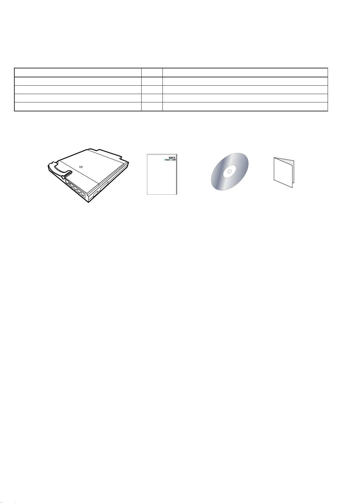
構成品一覧表
■N8406-022A 構成品
品名
数量
備考
GbE インテリジェントスイッチ(L2)
1
N8406-022A
ユーザーズガイド
1
本書
ソフトウェアマニュアル
1
CD-ROM
保証書
1
組込出荷時は添付されません。本体装置の保証書に記載されます。
本製品は以下の品目で構成されています。確認してください。
※ N8406-022Aの保証書について…
本製品をブレード収納ユニットに組み込んでお買い求め頂いた場合、ブレード収納ユニットに添付された保証書が
本製品の保証書を兼ねます。 ブレード収納ユニットの保証書に本製品の記載があるかご確認ください。
Page 3
User’s Guide
□
1Gb Intelligent L2 Switch
■ N8406- 022A
□
Warranty
□
Software manual
(CD-ROM)
□
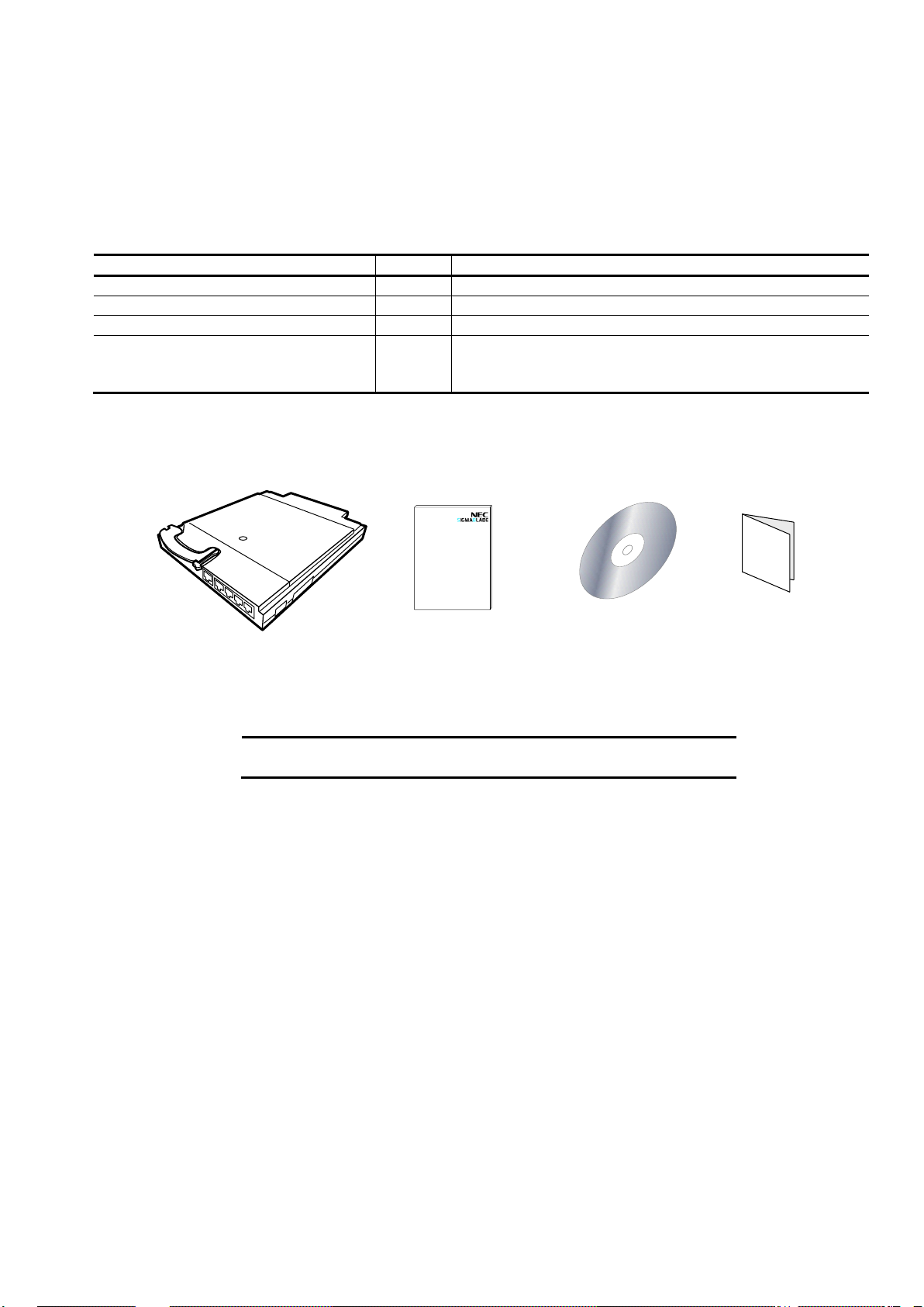
■N8406-022A Packaging List
Items
Quantity
Notes
1Gb Intelligent L2 Switch
1
N8406-022A
User’s Guide
1
This guide
Software manual
1
CD-ROM
Warranty
1
This is not included if the product is built into the system
at the time of shipment.
It is listed in the warranty of the Blade Enclosure.
NOTE: This warranty is available only for use in Japan.
Do not use it anywhere else other than Japan.
Packing List
This product is shipped with the following items. Verify the package contents.
Page 4

Page 5

この装置は、情報処理装置等電波障害自主規制協議会(VCCI)の基準に基づく
クラス A 情報技術装置です。この装置を家庭環境で使用すると電波妨害を引き
起こすことがあります。
この場合には使用者が適切な対策を講ずるよう要求されることがあります。
ご注意
1. 本書の内容の一部または全部について、許可なく複製・転載・翻訳・他形式・メディアへの変
換等を行うことは、禁止されています。
2. 本書の内容については、将来予告なしに変更することがあります。
3. 本書の内容については、万全を期して作成いたしましたが、万一お気付きの点や、ご不明の点
がありましたら、販売店または弊社までご連絡ください。
4. 本製品を運用した結果の影響については、上記 3 項にかかわらずいかなる責任も負いかねます
ので、ご了承ください。
5. 本書は、本体装置の操作に熟知した管理者、または保守員向けに記載されております。本体装
置の取り扱いや、各種 OS の操作、その他一般的かつ、基本的な事柄につきましては記載を省い
ておりますのであらかじめご了承ください。
NEC Corporation 2008
日本電気株式会社の許可無く、本書の複製・改変などを行うことはできません。
◆ 情報処理装置等電波障害自主規制協議会(VCCI)表示
Page 6

Note
1. No part of this guide may be reproduced, transmitted, translated in any form, or converted to
medias without prior written permission
2. The contents of this guide are subject to change without prior notice.
3. All efforts have been made to ensure the accuracy of all information in this guide. If you find any
part unclear, incorrect, or omitted in this guide, contact your service representative.
4. The company assumes no liability arising from the use of this product, nor any liability for
incidental or consequential damage arising from the use of this guide regardless of 3 above.
5. This guide is created for the manager or the maintenance person who is well informed about the
operation of this device. Note that the basic information, such as the operation procedures of the
device and OS, is omitted.
6. This equipment has been tested and found to comply with the limits for a Class A digital device,
pursuant to Part 15 of the FCC Rules. These limits are designed to provide reasonable
protection against harmful interference when the equipment is operated in a commercial
environment. This equipment generates, uses, and can radiate radio frequency energy and, if
not installed and used in accordance with the instruction guide, may cause harmful interference
to radio communications. Operation of this equipment in a residential area is likely to cause
harmful interference in which case the user will be required to correct the interference at his own
expense.
NEC Corporation 2008
No part of this guide may be reproduced or changed in any form without prior written permission of NEC
Corporation.
CE Statement
Warning: This is a Class A product. In domestic environment this product may cause radio interference in which
case the user may be required to take adequate measures (EN55022).
Canadian notice
This Class A digital apparatus meets all requirements of the Canadian Interference-Causing Equipment
Regulations.
Cet appareil numérique de la classe A respecte toutes les exigences du Règlement sur le matériel brouilleur du
Canada.
BSMI Statement
Page 7

目次
目次
使用上のご注意-必ずお読みください- ......................................................................... i
安全に関わる表示について .............................................................................................................. i
本書で使用する記号とその内容 ..................................................................................................... iii
安全上のご注意 .............................................................................................................................. iv
はじめに ..................................................................................................................... 1
本書について .............................................................................................................. 1
本文中の記号について ................................................................................................ ................... 1
関連マニュアル .......................................................................................................... 2
装置の概略 ................................................................................................................. 2
機能概要 ........................................................................................................................................ 2
各部の名称と役割 .......................................................................................................................... 5
ランプについて .............................................................................................................................. 6
本製品のポート構成について ........................................................................................................ 7
ブレード収納ユニット内における CPU ブレードと本製品のつながり ......................................... 9
N8406-013 GbE 拡張カードとのつながり(SIGMABLADE-M) ...................................................... 11
ネットワークケーブルついて ...................................................................................................... 13
設置 .......................................................................................................................... 14
取り付け手順 ................................ ................................ ................................ ............................... 14
取り外し手順 ................................ ................................ ................................ ............................... 16
設定方法 ................................................................................................................... 18
トラブルシューティング .......................................................................................... 22
仕様 .......................................................................................................................... 24
Page 8

Table Of Contents
Table of Contents
Precautions for Use........................................................................................... vii
Safety Indications ..................................................................................................................vii
Symbols Used in This User’s Guide ................................................................................ viii
安全注意事項 ................................................................................................................................. ix
Precautions for Safety..........................................................................................................xii
Introduction ....................................................................................................... 25
About this guide ................................................................................................ 25
Text Conventions .................................................................................................................. 25
Repurchasing This Guide.................................................................................................... 25
Additional references ...................................................................................... 26
Product Overview ............................................................................................. 26
Features .................................................................................................................................... 26
LED.............................................................................................................................................. 30
Number of ports .................................................................................................................... 31
Connection with CPU Blade ............................................................................................... 33
Connection with 1Gb Interlink Expansion Card ........................................................ 34
Network Cables ...................................................................................................................... 35
Installation ................................ ................................................................ ......... 36
Installation Procedure ........................................................................................................ 36
Removal Procedure .............................................................................................................. 37
Configuration ..................................................................................................... 39
Troubleshooting ................................................................................................ 43
Specification ....................................................................................................... 45
Page 9
本書は、必要なときすぐに参照できるよう、お手元に置いておく
ようにしてください。「使用上のご注意」を必ずお読みください。
使用上のご注意-必ずお読みください-
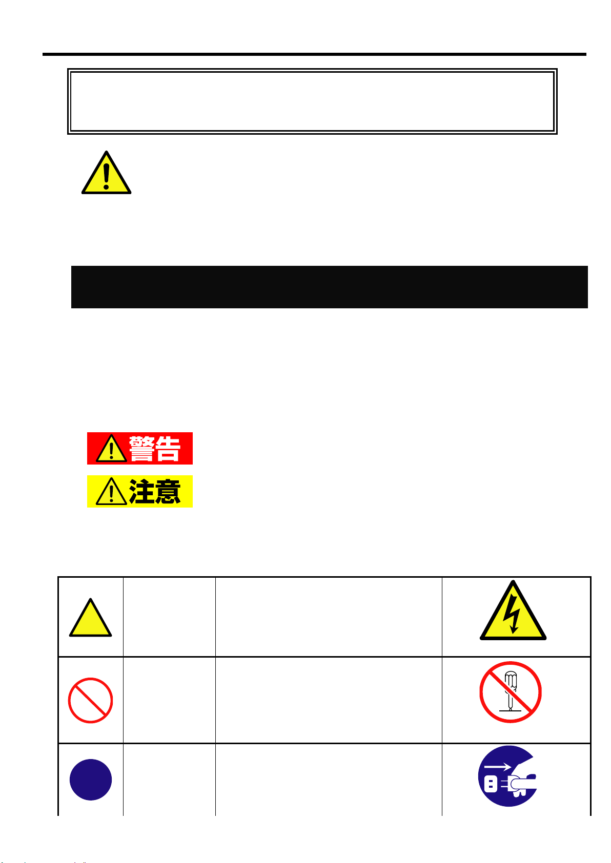
安全に関わる表示について
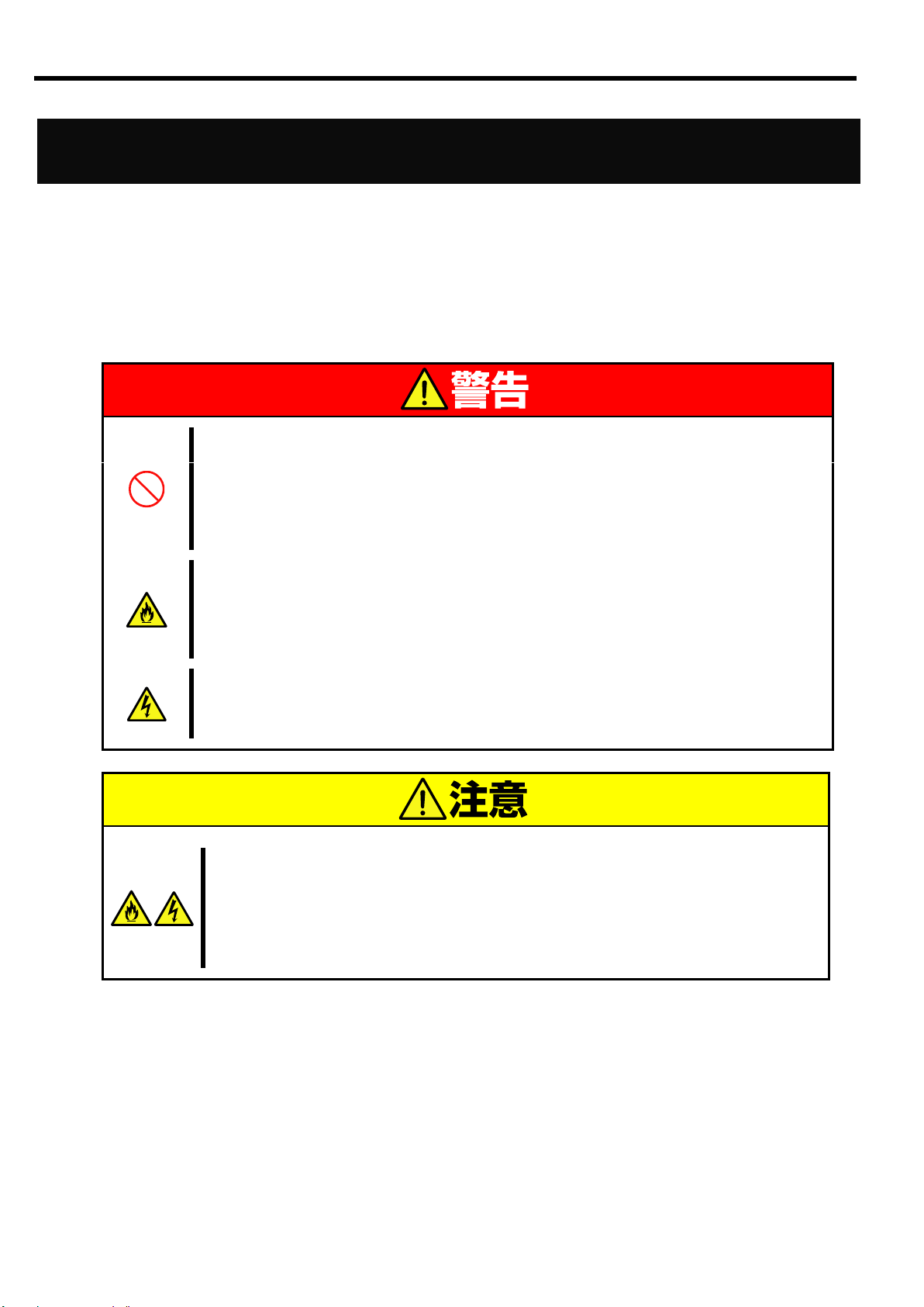
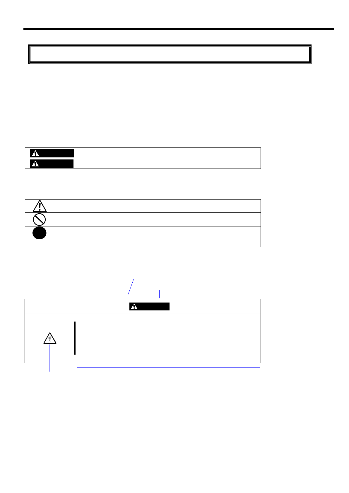
人が死亡する、または重傷を負うおそれがあることを示します。
火傷や怪我などを負うおそれや、物的損害を負うおそれがあるこ
とを示します。
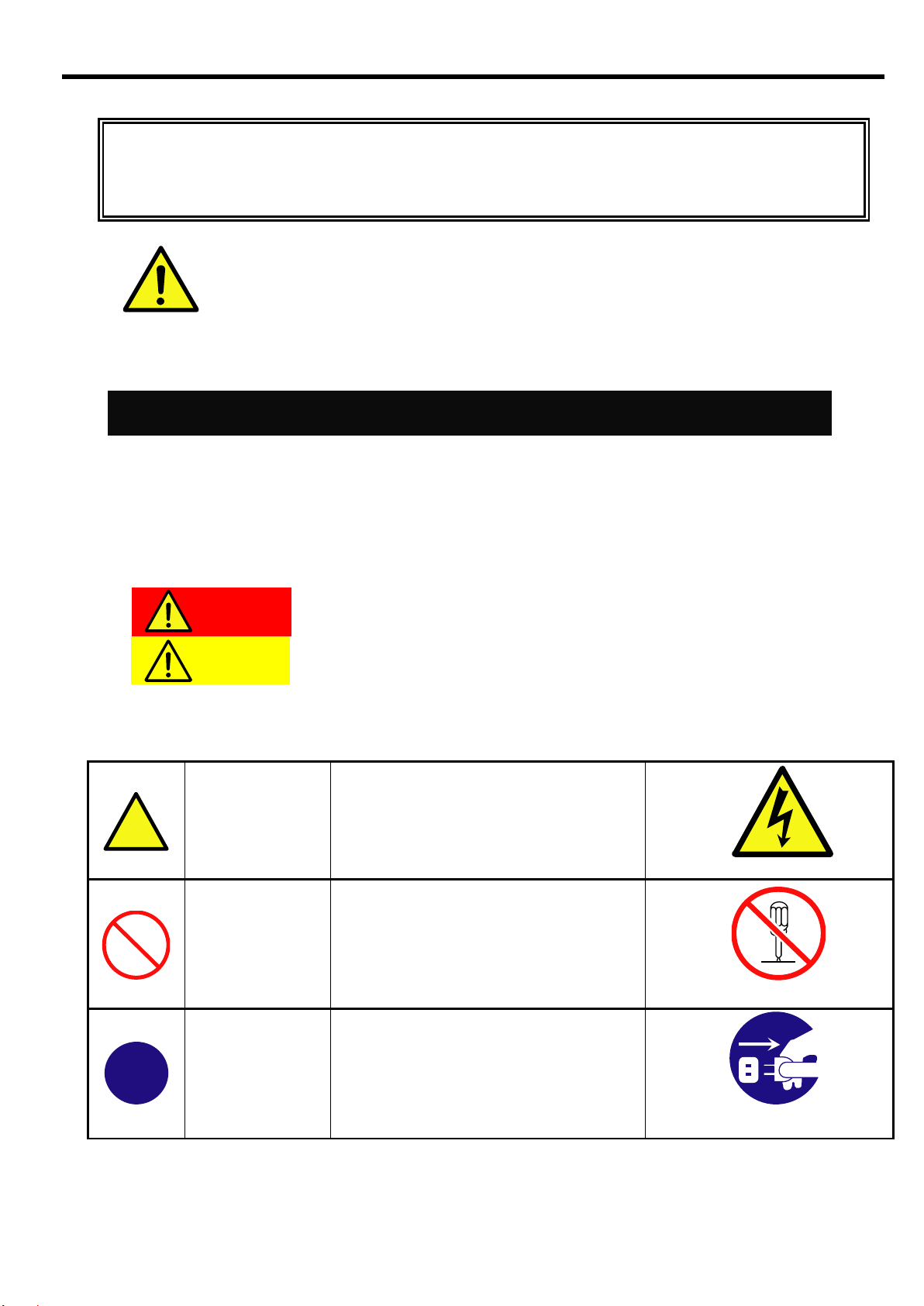
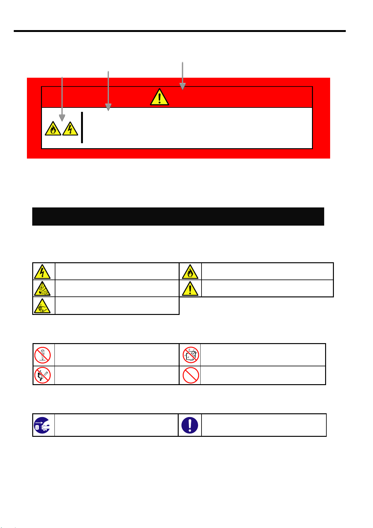
注意の喚起
この記号は、危険が発生するおそれがあ
ることを表します。記号の中の絵表示は
危険の内容を図案化したものです。
(例)
(感電注意)
行為の禁止
この記号は行為の禁止を表します。記号
の中や近くの絵表示は、してはならない
内容を図案化したものです。
(例)
(分解禁止)
行為の強制
この記号は行為の強制を表します。記号
の中の絵表示は、しなければならない行
為の内容を図案化したものです。危険を
避けるためには、この行為が必要です。
(例)
使用上のご注意(Japanese)
本製品を安全に正しくご使用になるために必要な情報が記載されています。また、本文中の名称については
ユーザーズガイドの「各部の名称と機能」の項をご参照ください。
本製品を安全にお使い頂くために、本書の指示に従って操作してください。
本書には、ご使用時に本製品のどこが危険でどのような危険に遭うおそれがあるか、どうすれば危険を避け
られるかなどについて記載されています。
本書では危険の程度を表す言葉として、「警告」と「注意」という用語を使用しています。
それぞれの用語は次の意味を持つものとして定義しています。
危険に対する注意・表示は次の 3 種類の記号を使って表しています。それぞれの記号は次のような意味を持
つものとして定義しています。
i
Page 10

(プラグを抜け)
使用上のご注意(Japanese)
ii
Page 11
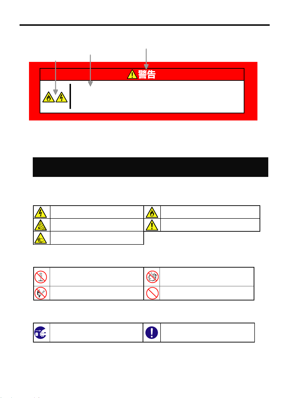
危険の程度を表す用語
危険に対する注意の内容
注意を促す記号
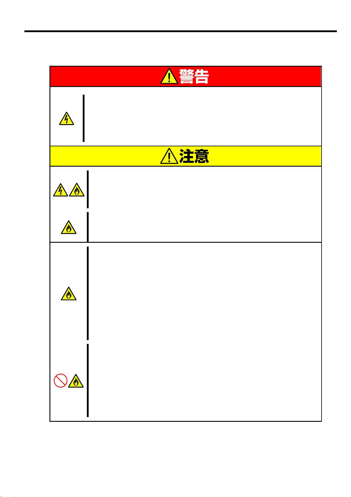
指定以外のコンセントに差し込まない
指定の電圧で、指定のコンセントをお使いください。
指定以外の電源を使うと火災や漏電の原因となります。
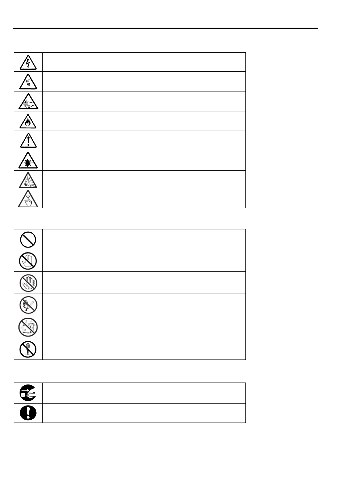
本書で使用する記号とその内容
感電のおそれのあることを示します。
発煙または発火のおそれがあることを示しま
す。
破裂のおそれがあることを示します。
特定しない一般的な注意。警告を示します。
指が挟まれて怪我をす るおそれがあるこ
とを示します
本装置を分解・修理・改造しないでくださ
い。感電や火災のおそれがあります。
水や液体がかかる場所で使用しないでくだ
さい。水に濡らすと感電や発火のおそれが
あります。
火気に近づけないでください。発火するお
それがあります。
特定しない一般的な禁止を示します。
ブレード収納ユニットの電源プラグをコ
ンセントから抜いてください。火災や感電
のおそれがあります。
特定しない一般的な使用者の行為を指示
します。説明に従った操作をしてくださ
い。
使用上のご注意(Japanese)
注意の喚起
行為の禁止
行為の強制
iii
Page 12
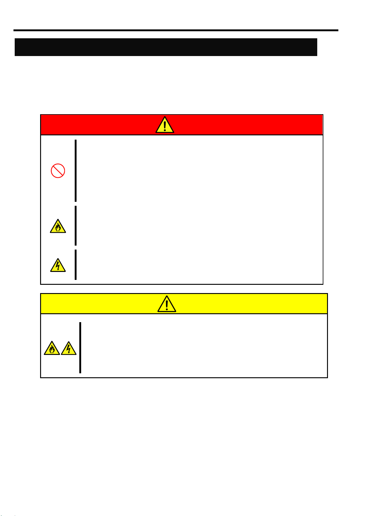
安全上のご注意
人命に関わる業務や高度な信頼性を必要とする業務には使用しない
本製品は医療機器・原子力設備や機器、航空宇宙機器・輸送設備や機器など、人命に
関わる設備および高度な信頼性を必要とする設備などには使用しないでください。
これらの設備に本製品を使用した結果、人身事故、財産損害などが生じても当社はい
かなる責任も負いかねます。
煙や異臭、異音がしたまま使用しない
万一、煙、異臭、異音などが生じた場合は、直ちにブレード収納ユニットの電源コー
ドをコンセントから取り外してください。その後、お買い求めの販売店または保守サ
ービス会社にご連絡ください。そのまま使用すると火災の原因となります。
針金や金属片を差し込まない
本製品に金属片や針金などの異物を差し込まないでください。感電の危険があります。
装置内に水や異物を入れない
本製品に水などの液体、ピンやクリップなどの異物を入れないでください。火災や感
電、故障の原因となります。もし入ってしまったときは、すぐにブレード収納ユニッ
トの電源を OFF にして、電源コードをコンセントから抜いてください。分解しないで、
販売店または保守サービス会社にご連絡ください。
使用上のご注意(Japanese)
本製品を安全にお使い頂くために、ここで説明する注意事項をよく読んで理解し、安全に活用してください。
記号の説明については「安全に関わる表示について」( i ページ)の説明を参照してください。
一般的な注意事項
iv
Page 13
ブレード収納ユニット内部に手を入れない
ブレード収納ユニットに装置を取り付け/ 取り外しをする際には、ブレード収納ユ
ニット内に手を入れないでください。感電するおそれがあります。また、ブレード収
納ユニットに取り付けられているカバーは装置の取り付けなど必要な場合を除いて
取り外さないでください。
指定以外の場所で使用しない
本製品は、専用の「ブレード収納ユニット」に搭載して使用します。ブレード収納
ユニット以外やその他の筐体(ケース)に取り付けて使用しないでください。火災
や感電の原因となります。
通気口をふさがない
装置にある通気口をふさがないでください。装置内部の温度が上がり、火災の原因
となるおそれがあります。
指定以外のインタフェースケーブルを使用しない
インタフェ-スケーブルは、適合するものを使用し、接続する装置やコネクタを確
認した上で接続してください。指定以外のケーブルを使用したり、接続先を誤った
りすると、ショートにより火災を起こすことがあります。
また、インタフェ-スケーブルの取り扱いや接続について、次の注意をお守りくだ
さい。
破損したケーブルコネクタを使用しない
ケーブルを踏まない
ケーブルの上にものを載せない
ケーブルの接続がゆるんだまま使用しない
破損したケーブルを使用しない
腐食性ガスの存在する環境で使用または保管しない
腐食性ガス(二酸化硫黄、硫化水素、二酸化窒素、塩素、アンモニア、オゾンなど)
の存在する環境に設置し、使用しないでください。
また、ほこりや空気中に腐食を促進する成分(塩化ナトリウムや硫黄など)や導電
性の金属などが含まれている環境へも設置しないでください。装置内部のプリント
板が腐食し、故障および発煙・発火の原因となるおそれがあります。
もしご使用の環境で上記の疑いがある場合は、販売店または保守サービス会社にご
相談ください。
使用上のご注意(Japanese)
設置・移動・保管・接続に関する注意事項
v
Page 14
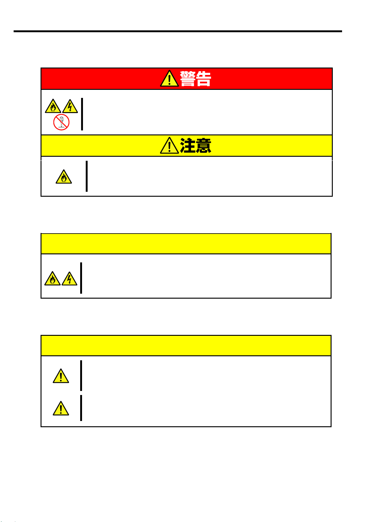
分解・修理・改造はしない
本製品を分解したり、修理・改造を行ったりしないでください。感電や火災の危険が
あります。
中途半端に取り付けない
インタフェースケーブルは確実に取り付けてください。中途半端に取り付けると接
触不良を起こし、発煙や発火の原因となるおそれがあります。
ペットを近づけない
本製品にペットなどの生き物を近づけないでください。排泄物や体毛が装置内部に
入って火災や感電の原因となります。
本製品を廃棄する場合は各自治体の条例に従ってください
詳しくは、各自治体にお問い合わせください
本製品を他人に譲渡する場合は、本書および添付品すべてを必ず一緒に渡
してください。
廃棄・譲渡に関する注意事項
運用中の注意事項
使用上のご注意(Japanese)
お手入れ・内蔵機器の取り付けに関する注意事項
運用中の注意事項
廃棄・譲渡に関する注意事項
vi
Page 15
Precautions for Use
-Be sure to read this section -
Safety Indications
Indicates the presence of a hazard that may result in death or serious
personal injury if the instruction is ignored.
Indicates the presence of a hazard that may cause minor personal injury,
including burns, or property damage if the instruction is ignored.
Attention
This symbol indicates the
presence of a hazard if the
instruction is ignored. An image in
the symbol illustrates the hazard
type.
Example
(Electric hazard)
Prohibited
action
This symbol indicates prohibited
actions. An image in the symbol
illustrates a particular prohibited
action.
Example
(Do not disassemble)
Mandatory
action
This symbol indicates mandatory
actions. An image in the symbol
illustrates a mandatory action to
avoid a particular hazard.
Example
(Unplug)
Keep this User’s Guide handy for quick reference
when necessary.
Be sure to read this section carefully.
CAUTION
WARNING
Precautions for Use
The following includes information necessary for proper and safe operation of the product.
See the “Product Overview” chapter for the term in this guide.
Follow the instructions in this User's Guide for your safety to use this product.
The server contains components that may pose possible danger, hazards that may be caused by ignoring
warnings, and preventive actions against such hazards.
The words “WARNING” and “CAUTION” are used to indicate the degrees of danger.
These terms are defined as follows:
This guide uses the following three types of symbols to give indications and precautions against a danger.
They are defined as follows:
vii
Page 16
Term indicating a degree of danger
Description of a danger
Symbol to draw attention
Do not plug the power cord into a nonconforming outlet
Use a wall outlet with specified voltage and power type.
Otherwise, there is a risk of a fire or current leakage.
Symbols Used in This User’s Guide
Indicates that improper use may cause an
electric shock.
Indicates that improper use may cause fumes
or fire.
Indicates that improper use may cause
explosion.
Indicates a general notice or warning that
cannot be specifically identified.
Indicates that improper use may cause
fingers to be caught.
Do not disassemble, repair, or modify this
product. Otherwise, there is a risk of an
electric shock or fire.
Keep the product away from water.
Otherwise, there is a risk of an electric
shock or ignition.
Never put this product close to a flame.
Otherwise, there is a risk of a fire.
Indicates a general prohibited action.
Unplug the power cord of the Blade
Enclosure. Otherwise, an electric shock or
fire may be caused.
Indicates a mandatory action that cannot
be specifically identified. Make sure to
follow the instruction.
WARNING
Precautions for Use
Attentions
Prohibited actions
Mandatory actions
viii
Page 17
安全注意事項
WARNING
表示如不遵守該指示,可能引發人員傷亡。
CAUTION
表示如不遵守該指示,可能發生燒傷等身體損傷或造成物質損失。
表示該處可能發生危險。符號為危險內容的圖案。(注意)
表示禁止行為。符號中或其附近的圖案為禁止行為內容。(禁止行為)
表示強制行為。符號中的圖案為強制必須做的行為內容。即為避免危險必需的
行為。(強制行為)
注意符號
表示危險程度的用語
CAUTION
注意高溫。
本產品關閉電源後,內置硬碟等內部設備仍然處於高溫狀態。請在充
分冷卻之後進行拆裝。
禁止行為的提示符號(有
可能沒有此類提示)
危險提示內容
Precautions for Use
安全標示
請參考本用戶指南中的指示以安全使用NEC SIGMABLADE系列伺服器。
本用戶指南說明了設備何處有危險、危險類型、如何避免危險等。在設備可預計到的危險之處或其附近貼有警告標籤。
用戶指南及警告標籤中,根據危險程度不同,使用“警告”、“注意”等詞,含義如下:
對危險的提示表示有如下三種符號,具體含義如下所述:
(用戶指南中範例)
ix
Page 18
表示有觸電的危險。
表示有因高溫而負傷的危險。
表示有手指等被夾住的危險。
表示有冒煙或者著火的危險。
表示非特定的一般的提醒警告。
表示有因雷射導致失明的危險。
表示有爆炸的危險。
表示有受傷的危險。
表示非特定的一般禁止。
不要觸摸指定區域。有觸電或著火的危險。
不要用濕手觸摸。有觸電的危險。
遠離火源。有著火的危險。
遠離液體。如果沾到液體,有觸電或著火的危險。
請不要對本設備進行拆卸、修理、改造。有觸電和發生火災的危險。
請將本設備的電源插頭從伺服器上拔下。有發生火災和觸電的危險。
對非特定的一般使用者的行為進行指示。請按照說明進行操作。
Precautions for Use
注意
本書及警告標籤中使用的符號
禁止行為
強制行為
x
Page 19

Precautions for Use
注意: 本產品通過多餘的硬體模組提供硬體容錯性能。但是這並不表示能夠保證完全容錯。
如,在以下情況下可能發生宕機:
– 軟體發生致命故障。
– 多餘硬體雙方均發生故障,不能運行。
– 時鐘產生器線路或內部連接背板等非多餘元件發生致命故障。
– 切斷了整個系統的AC電源
xi
Page 20
Precautions for Safety
Do not use the product for services where critical high availability
may directly affect human lives.
The product is not intended to be used with or control facilities or devices concerning
human lives, including medical devices, nuclear facilities and devices, aeronautics
and space devices, transportation facilities and devices; and facilities and devices
requiring high reliability. NEC assumes no liability for any accident resulting in
personal injury, death, or property damage if the product has been used in the above
conditions.
Do not continue to use the equipment if you detect smoke, odor, or
noise
If the equipment emits smoke, odor, or noise, immediately unplug the power cord of
the Blade Enclosure. Then, contact your service representative. Continuing to use the
product in such conditions may cause a fire.
Do not insert a wire or metal object
Do not insert a wire or metal object into this product.
There is a risk of an electric shock.
Keep water or foreign matter away from the equipment.
Do not let any form of liquid (water etc.) or foreign matter (e.g., pins or paper clips)
enter the equipment. Failure to follow this warning may cause an electric shock, a
fire, or a failure of the equipment. When such things accidentally enter the equipment,
immediately turn off the power of the Blade Enclosure and unplug the AC cord. Then,
contact your service representative.
CAUTION
WARNING
Precautions for Use
This section provides precautions for using this product safely. Read this section carefully to ensure proper
and safe use of the server. For symbol meanings, see “Safety Indications” on page vii.
General Precautions
xii
Page 21
Do not place yours hand inside the Blade Enclosure.
When you are installing/removing the product in/from the Blade Enclosure, do not
place your hands inside the Blade Enclosure. Doing so may cause an electrical
shock. Do not remove the cover from the Blade Enclosure unless you are installing
the device in it.
Use the product only in the specified places
This product should be installed in a dedicated Blade Enclosure. Do not install the
product in a chassis other than the Blade Enclosure. Failure to do so may result in
fire and/or electric shock to occur.
Do not block the air openings
Do not block the air openings. When they are blocked, the internal temperature will
rise and may cause a fire.
Do not use any unauthorized interface cable.
Use only interface cables authorized by NEC and locate a proper device and
connector before connecting a cable. Using an unauthorized cable or connecting a
cable to an improper destination may cause a short circuit, resulting in a fire.
Also, observe the following notes on using and connecting an interface cable:
Do not use a damaged cable connector.
Do not step on the cable.
Do not put any object on the cable.
Do not use a card with a loose interface cable connection.
Do not use a damaged cable.
Do not use the equipment in a place where corrosive gases exist.
Make sure not to locate or use the equipment in a place where corrosive gases
(sulfur dioxide, hydrogen sulfide, nitrogen dioxide, chlorine, ammonia, ozone, etc)
exist.
Also, do not locate it in an environment where the air (or dust) includes components
accelerating corrosion (ex. sulfur, sodium chloride) or conductive metals.
There is a risk of a fire due to corrosion and shorts of the internal printed circuit
board.
CAUTION
WARNING
Precautions for Use
Precautions for Installation, Relocation, Storage and Connection
xiii
Page 22

Do not disassemble, repair, or modify the product yourself
Do not disassemble, repair, or modify this product. Doing so may cause an electrical
shock or a fire. Do not put the product close to fire or immerse it in water. Doing so
may cause an explosion. If the product does not function normally, contact your
service representative.
Make sure to complete device installation
Securely connect the interface cables. Loose connections may cause a fire.
Keep animals away from the product
Keep animals away from the product. Animal waste or hair may enter the equipment
and cause a fire or electrical shock.
Follow the ordinances of your local government when you dispose the product.
Contact the local government for more information.
When you transfer this product to a third party, make sure to provide all items that
come with the product, including this guide.
CAUTION
WARNING
Precaution on operation
Precaution on disposing or transferring
Precautions for Use
Precautions for Cleaning and Handling of Internal Devices
Precaution on operation
Precaution on disposing or transferring
xiv
Page 23

(Japanese)
本文中の記号について
装置の取り扱いや、ソフトウェアの操作で守らなければならない事柄
や、特に注意すべき点を示します。
装置やソフトウェアを操作する上で確認しておく必要がある点を示し
ます。
知っておくと役立つ情報や、便利なことを示します。
はじめに
このたびは、「N8406-022A GbE インテリジェントスイッチ(L2)」をお買い求めいただき、誠にありがとうございま
す。
本製品の持つ機能を最大限に引き出すためにも、ご使用になる前に本書をよくお読みになり、装置の取り扱いを
十分にご理解ください。
本書について
本書は、本製品を正しくセットアップし、安全に使用できるようにするための手引きです。製品のセットアップ
を行うときや製品の取り扱いがわからないときなどにご利用ください。
本書は常に製品のそばに置いて いつでも見られるようにしてください。
本書では巻頭で示した安全に関わる注意記号の他に、3 種類の記号を使用しています。
これらの記号と意味をご理解になり装置を正しくお取り扱いください。
1
Page 24

機能概要
(Japanese)
関連マニュアル
本製品の設定方法につきましては、添付 CD-ROM に収められている以下のドキュメントを参照してください。
・ N8406-022A GbE インテリジェントスイッチ(L2) アプリケーションガイド
・ N8406-022A GbE インテリジェントスイッチ(L2) コマンドリファレンスガイド(AOS)
・ N8406-022A GbE インテリジェントスイッチ(L2) コマンドリファレンスガイド(ISCLI)
・ N8406-022A GbE インテリジェントスイッチ(L2) ブラウザベースインタフェースリファレンスガイド
・ N8406-022A GbE インテリジェントスイッチ(L2) スマートパネルリファレンスガイド
装置の概略
この章では本製品の機能概要について説明します
本製品は、SIGMABLADE 用のインテリジェント・レイヤ2スイッチです。ブレード収納ユニットのスイッチモジュールス
ロットに装着して使用します。
CPU ブレード向けのポートとして内部に 16 ポート、また隣接スロットへの内部接続用(インターリンク)に 2 ポート装備
しており、外部ポートには 10/100/1000Mbps 対応のイーサネットポートを 5 ポート装備しています。
また、本スイッチには2種類のスイッチソフトウェアが格納されています。1つは通常の L2 スイッチ機能が動作する
ソフトウェア(スイッチモード)、もう 1 つはスイッチ機能を絞り込み、簡単に設定可能にした、スマートパネルとい
うソフトウェア(スマートパネルモード)です。この 2 つのうち、どちらかを選択して本スイッチを使用します。
なお、スマートパネルモードでは、インターリンクの 2 ポートは使用できません。
■スイッチモードのサポート機能
・レイヤ2スイッチ機能
・VLAN
- ポートベース VLAN
- タグベース VLAN (802.1q)
・スパニングツリー
- Spanning Tree Protocol (802.1D)
- Rapid Spanning Tree Protocol (802.1w)
- Multiple Spanning Tree Protocol (802.1s)
・リンクアグリゲーション (ポートトランク機能)
- スタティック
- LACP
・Uplink Failure Detection (トランクフェールオーバ機能)
・ジャンボフレーム (最大 9K)
・ポートミラーリング
・AutoMDI/MDI-X 機能
・IGMP スヌーピング (v1,v2)
・NTP クライアント
・DNS クライアント
・Syslog
・SNMP v1,v2c,v3
・RMON (グループ 1,2,3,9)
・HTTP/HTTPS サーバ
・TELNET サーバ/クライアント
2
Page 25

・SSH/SCP (公開鍵認証/パスワード認証)
・ 本製品のトラップを ESMPRO/ServerManager のアラートビューアで表示するため
の手順につきましては添付 CD-ROM の Readme_J.txt を参照してください。
・ WebSAM NetvisorPro と併用して本製品を運用される場合は、スイッチソフトウェア
はスイッチモードを、CLI は ISCLI を使用してください。
・TFTP/FTP クライアント
・BOOTP/DHCP クライアント
・ユーザ認証機能
- RADIUS
- TACACS+
・管理インタフェース
- コマンドラインインタフェース (以下 CLI と略します)
以下の 2 通りのコマンド形式から選択
* AOS ・・・コマンド構造がメニューベース
AOS のコマンドリファレンスガイドを参照してください。
* ISCLI ・・・コマンド構造がツリーベース
ISCLI のコマンドリファレンスガイドを参照してください。
- ブラウザベースインタフェース (BBI)
Web ブラウザを通しての管理インタフェースです。
詳細は BBI のリファレンスガイドを参照してください。
■スマートパネルモードのサポート機能
・レイヤ2スイッチ機能
・VLAN
- ポートベース VLAN
- タグベース VLAN (802.1q)
・リンクアグリゲーション (ポートトランク機能)
- スタティック
- LACP
・フェイルオーバ機能
・ジャンボフレーム (最大 9K)
・AutoMDI/MDI-X 機能
・IGMP スヌーピング (v1,v2)
・NTP クライアント
・Syslog
・SNMP v1,v2c,v3
・HTTP/HTTPS サーバ
・TELNET サーバ/クライアント
・SSH/SCP (公開鍵認証/パスワード認証)
・TFTP/FTP クライアント
・DHCP クライアント
・ユーザ認証機能
- RADIUS
- TACACS+
・管理インタフェース
- コマンドラインインタフェース (AOS)
スマートパネルモードには ISCLI はありません。
- ブラウザベースインタフェース (BBI)
Web ブラウザを通しての管理インタフェースです。
詳細はスマートパネルリファレンスガイドを参照してください。
(Japanese)
3
Page 26

(Japanese)
4
Page 27

N8 406-022A
R ST
20 21 22 2 3 2 4
1
2
3
4 5
6
7
8
各部の名称と役割
名称
機能
1.イジェクタ
本製品をブレード収納ユニットへ着脱するときの操作レバー
2.RESET スイッチ
本製品をリセットするスイッチ
このリセットにより本スイッチが再起動します。保存していない設定情報は
失われます。また、一時的に相手装置とのリンクが切断されます。
3.STATUS ランプ
本製品の状態を表示するランプ
電源 ON 後 5 分以上経っても緑色に変わらない場合は、保守サービス会社に連絡して
ください。
4.ID ランプ
装置を識別するためのランプ
5.シリアルポート
(コンソールポート)
ローカルコンソール接続用ポート(DB-9)。
ご使用になるにはオプションのシリアルケーブル(K410-84(05))が必要です。
6.ユーザポート
ブレード収納ユニットの外部のネットワーク機器に接続するためのポート(RJ-45)。
CPU ブレードとは、本製品に内蔵しているレイヤ 2(L2)スイッチングチップを介して
接続されます。
本製品のユーザポートの上部に表示される数字はポート番号に対応しています。
7.LINK/ACT ランプ
LAN ポートの LINK 状況とデータの送受信状況を示すランプ
消灯
リンクダウン
点灯(グリーン:緑色)
リンク確立
点滅
データの送受信
8.SPEED ランプ
リンク速度を示すランプ
消灯
10Mbps
点灯(グリーン:緑色)
100Mbps
点灯(アンバー:橙色)
1000Mbps
本製品はブレード収納ユニットの電源の状態と連動して動作します。本製品には電源O
N/
OFFスイッチはありません。
■ N8406-022A
(Japanese)
5
Page 28
ランプについて
STATUS ランプの状
態
意味
対処方法
緑色に点灯
正常に動作しています
-
消灯
電源が OFF になっています
-
アンバー(橙色)に点滅
次の異常を検出しました
温度異常
内蔵 CPU の異常 等
ブレード収納ユニット(SIGMABLADE-M)で
は SIGMABLADE モニターに異常内容が表示
されます。詳細は EM カードのユーザーズ
ガイドを参照してください。エラー種別に
よっては保守サービス会社に連絡してく
ださい。
スイッチモジュールインタ
フェースミスマッチ
ブレード収納ユニット(SIGMABLADE-M)で
は SIGMABLADE モニターに
「SWMn IFmiss Alm」が表示されます。「ブ
レード収納ユニット内における CPU ブレードと
本製品のつながり」(9 ページ)を確認して、
CPU ブレードのインタフェース種別(FC ま
たは LAN)と本製品のインタフェース種別
が一致しているか確認してください。
ID ランプの状態
意味
青色に点灯または点滅
操作対象であることを管理ソフトウェアなどにより設定された
消灯
上記以外
(Japanese)
STATUS ランプ
本製品やブレード収納ユニットが正常に動作している間は STATUS ランプが緑色に点灯します。STATUS ランプがア
ンバー(橙色)に点灯または点滅しているときは、システムに何らかの異常が発生したことを示します。異常を示
しているときは保守サービス会社に連絡してください。
ID ランプ
操作対象の製品であることを識別するためのランプ。
複数台の装置の中から、特定の装置を識別したいときに使用できます。
メンテナンスの時などに、このランプを点灯させておくと、対象装置を間違えずに作業することができます。
6
Page 29

本製品のポート構成について
インタフェース名
ポート
番号
速度
説明
内部インタフェース
CPU ブレードポート
1~16
1000Mbps
CPU ブレード接続専用のポートです。各ポートが、
ブレード収納ユニットのブレードスロットに実装さ
れる各 CPU ブレードに接続します。また、ブレード
収納ユニットにより接続が異なります。詳細は「ブ
レード収納ユニット内における CPU ブレードと本製品のつ
ながり」(9 ページ)を参照してください。
インターリンクポート
17~18
1000Mbps
ブレード収納ユニットの隣接スロットと接続するた
めの内部ポートです。
スイッチモードでは、デフォルトで、ポート 17,18
でトランクを構成していますが、ポートは無効にな
っています。
スマートパネルモードでは、ポート 17,18 は使用で
きません。
マネジメントポート
19
10/100Mbps
ブレード収納ユニット内部の管理用 LAN に接続する
ためのポートです。他のポートとは VLAN を分離して
おり通信できません。管理専用でお使いください。
ご使用の際はブレード収納ユニットの外部ポートか
ら接続します。詳細はブレード収納ユニットのユー
ザーズガイドを参照してください。
外部インタフェース
ユーザポート
20~24
10/100/
1000Mbps
外部ネットワークへの接続用のイーサネットポート
です。10Base-T,100Base-TX,1000Base-T に対応して
います。
シリアルポート
(コンソールポート)
-
9600bps
ローカルコンソール接続のポートです。コネクタ形
状は DB-9 です。
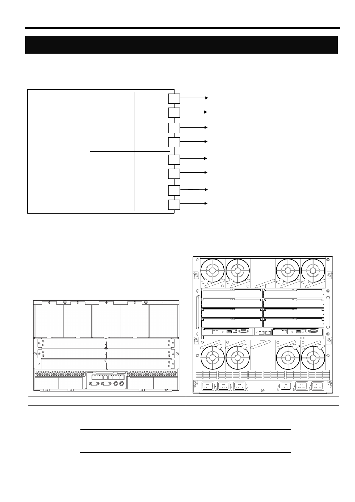
本製品のポート構成と内部での接続を以下に示します。
本製品のインタフェースは大きく分けて内部インタフェースと外部インタフェースがあります。
(Japanese)
7
Page 30

port
20
スイッチモジュール外部
Ethernetインタフェース
(ユーザポート)
シリアルポート
(コンソールポート)
port
1
port
16
port
17
C PU ブレードまたは
N 8406-013 G bE 拡張カードへ
port
19
収納ユニット内部
管理用LA N へ
N 8 4 0 6 -0 22A
G b E インテリジェントスイッチ(L 2 )
外部インタフェース
内部インタフェース
EM カードへ
隣接スロットへ
10/100/1000Mbps
10/100Mbps
1000Mbps
固定
1000Mbps
固定
C P U ブレードポート
インターリンクポート
(In terlin k p o rt)
制御用
C P U
制御用
インタフェース
レイヤ2 (L 2 )
スイッチングL S I
マネジメントポート
port
18
port
24
(Japanese)
【N8406-022A GbE インテリジェントスイッチ(L2)の内部/外部ポートの構成図】
8
Page 31

(Japanese)
ブレード収納ユニット内における CPU ブレードと本製品のつな
がり
C PU ブレード
(Express5800/120Bb-6)
標準LAN
メザニン拡張
スロット1
(Type-1専用)
メザニン拡張
スロット2
(Type-1,2共用)
ポート2
ポート1
ポート2
ポート1
ポート2
ポート1
スロット6 へ
スロット5 へ
スロット4 へ
スロット3 へ
スロット2 へ
スロット1 へ
S IG M A B L A D E -M の場合…スロット6 へ
S IG M A B L A D E -H の場合…スロット8 へ
ポート4
ポート3
S IG M A B L A D E -M の場合…スロット5 へ
S IG M A B L A D E -H の場合…スロット7 へ
スイッチモジュールスロット5
スイッチモジュールスロット3
スイッチモジュールスロット1
スイッチモジュールスロット6
スイッチモジュールスロット4
スイッチモジュールスロット2
スイッチモジュールスロット1
スイッチモジュールスロット3
スイッチモジュールスロット5
スイッチモジュールスロット7
スイッチモジュールスロット2
スイッチモジュールスロット4
スイッチモジュールスロット6
スイッチモジュールスロット8
SIGMABLADE-M
SIGMABLADE-H
ブレード収納ユニット背面
ブレード収納ユニット内での CPU ブレードと本製品のつながりを示します。
本製品をブレード収納ユニットに搭載するにあたって参考にしてください。
メザニン拡張スロット 2 のポート 3,4 はブレード用タイプ 2 メザニンカードを装着した場合に接続されます。
ブレード収納ユニットのスイッチモジュールスロット番号
※ ブレード収納ユニット(SIGMABLADE-H)のスロット 7,8 は、CPU ブレードでブレード用タイプ 2 メザニンカ
9
Page 32

(Japanese)
ードを装着した場合に限り本製品を搭載して使用することができます。
10
Page 33

(Japanese)
port
20
ユーザポート
シリアルポート
(コンソールポート)
port
1
port16port
17
port
19
N 8 40 6-0 22A
G b E インテリジェントスイッチ (L2 )
10/100/1000Mbps
10/100Mbps
1000Mbps
固定
1000Mbps
固定
C P U ブレードポート
制御用
C P U
制御用
インタフェース
レイヤ2 (L 2 )
スイッチングL S I
port
18
port
24
N 8 4 0 6 -0 1 3
G b E 拡張カード
C P U
ブレード
port
20
ユーザポート
シリアルポート
(コンソールポート)
port
1
port16port
17
port
19
N 8 40 6-0 22A
G b E インテ リジェントスイッチ(L2 )
10/100/1000Mbps
10/100Mbps
1000Mbps
固定
1000Mbps
固定
C P U ブレードポート
制御用
C P U
制御用
インタフェース
レイヤ2 (L 2 )
スイッチングL S I
port
18
port
24
メザニン拡張
スロット1
標準
LAN
p o rt1 へ p o rt9 へ p o rt1 へ p o rt9 へ
スイッチモジュール
スロット#1
スイッチモジュール
スロット#2
スイッチモジュール
スロット#3,4
ブレード
スロット#1
N8406-013 GbE 拡張カードとのつながり(SIGMABLADE-M)
CPU ブレード
スロット番号
メザニン拡張スロット
1 のポート番号
接続先スイッチモジュール
スロット番号
N8406-022 への
接続ポート番号
1
1 1 9
2 2 9
2
1 1 10
2 2 10
3
1 1 11
2 2 11
1 1 12
ブレード収納ユニット(SIGMABLADE-M)では、通常 本製品のポート 9~16 を使用しません。
N8406-013 GbE 拡張カードをブレード収納ユニットのスイッチモジュールスロット 3,4 に増設することにより、CPU
ブレードのメザニン拡張スロット 1 の出力を、ブレード収納ユニットのスイッチモジュールスロット 1,2 に搭載
した本製品のポート 9~16 に接続することができます。
これにより本製品のポートを余すことなく使用することができます。
N8406-013 を接続した場合、CPU モジュールのメザニン拡張スロット 1 のポートと本製品の接続の対応は以下のよ
うになります。
11
Page 34

2 2 12
5
1 1 13
2 2 13
6
1 1 14
2 2 14
7
1 1 15
2 2 15
8
1 1 16
2 2 16
(Japanese)
12
Page 35
ネットワークケーブルついて
コネクタ
RJ-45
ケーブルタイプ
ツイストペアケーブル( UTP / STP )
8 芯 4 ペア
規格
EIA/TIA 規格準拠
*使用される通信速度により要求されるケーブルの品質が異なります。
10Base-T
100Base-TX
1000Base-T
カテゴリ 3 以上
カテゴリ 5 以上
カテゴリ 5e 以上
ケーブル長
最大 100 メートル
ケーブルポートをお使いになる場合
次の仕様を満たすケーブルをお使いください
(Japanese)
13
Page 36

取り付け手順
1
本製品のイジェクタのストッパーをはず
し、イジェクタを開く
イジェクタ
ストッパー
2
本製品のイジェクタを開いたまま、ゆっく
りとていねいにブレード収納ユニットに
差し込む。
イジェクタ
ブレード収納ユニット
3
イジェクタをストッパーがロックされる
まで押し込み、ブレード収納ユニットに固
定する。
ブレード収納ユニット
ストッパー
(Japanese)
設置
ブレード収納ユニットへの本製品の取り付け方法について説明します。
詳しくはブレード収納ユニットのユーザーズガイドをご覧になってください。
14
Page 37

・ ブレード収納ユニットに本製品を取り付けられないときは、いったん本製品を取り外
してから取り付けなおしてください。無理な力を加えると破損するおそれがあります
ので注意してください。
・ 本製品の取り付け・取り外し方法はブレード収納ユニットにより異なりますので必ず
ブレード収納ユニットのユーザーズガイドをお読みください。
・ 本製品はブレード収納ユニットの電源の状態と連動して動作します。電源供給されて
いるブレード収納ユニットに本製品を取り付けると、本製品にもすぐに電源供給され
稼動開始します。そのため、本製品を実装するスイッチモジュールスロットに接続さ
れる CPU ブレード側のポートが、標準 LAN もしくはオプションの 1000BASE-T 接
続ボードであることを十分ご確認の上、本製品を取り付けてください。
・ 本製品には電源ON/OFFスイッチはありません。
・ 本製品の取り付け後、約 10 秒で STATUS ランプが緑色に点灯します。
(Japanese)
15
Page 38

取り外し手順
1
本製品のストッパーをはずし、イジェクタ
を開いてロックを解除する。
ブレード収納ユニット
ストッパー
2
本製品のイジェクタを手前に軽く引いて
ください。
ブレード収納ユニット
イジェクタ
3
本製品のイジェクタを開いたまま、本製品
をしっかりと持ってゆっくりと引き出す。
ブレード収納ユニット
イジェクタ
(Japanese)
本製品の取り外しについて説明します。
詳しくはブレード収納ユニットのユーザーズガイドをご覧になってください。
16
Page 39

・ 本製品をスイッチモジュールスロットから取り外し、再度取り付ける場合は 30 秒以
上時間をおいて取り付けてください。
・ ブレード収納ユニットのスイッチモジュールスロットに、本製品ならびにその他のス
イッチモジュールを搭載しない場合は、スイッチモジュールスロットにブランクカバ
ーを取りつけて運用してください。
・ ブレード収納ユニットのブランクカバーの取り付け方法は、ブレード収納ユニットの
ユーザーズガイドを参照してください。
(Japanese)
17
Page 40

通信速度
9600 bps
データ長
8 ビット
パリティ
なし
ストップビット
1 ビット
フロー制御
なし
・ シリアルポートコネクタには専用回線を直接接続することはできません。
・ スイッチモードのコマンドラインインタフェースには、AOS と ISCLI の2つのモー
ドがあります。どちらかのモードを選択して使用してください。デフォルト設定では
AOS で起動します。
・ WebSAM NetvisorPro と併用して本製品を運用される場合は、スイッチソフトウェア
はスイッチモードを、CLI は ISCLI を使用してください。
・ 本製品では、EM カードからのシリアルインタフェース接続はサポートしていません。
そのため、CONNECT SWITCH (SIGMABLADE-H)、connectswitch (SIGMABLADE-M)
コマンドによる、EM カードからのシリアルコンソール接続はできません。
(Japanese)
設定方法
本製品はシリアルポート経由でローカルコンソールにログインするか、ネットワーク経由でリモートコンソール
にログインして設定することができます。
・ローカルコンソール接続
本製品のシリアルポートと管理用コンソール間をシリアルケーブルで接続します。本製品のコマンドラインイ
ンタフェースにアクセスし、ログインプロンプトが表示されます。なお、ケーブルはオプションのシリアルケ
ーブル(K410-84(05))が必要です。また、管理用コンソールには VT-100 準拠の通信ソフトウェアが必要です。
通信ソフトウェアは下表の通り設定してください。
・リモート接続
ネットワーク経由のリモート接続をするためには、本装置に IP アドレスを設定する必要があります。設定した
IP アドレスに対して telnet や Web ブラウザを通して接続し、CLI/BBI にアクセスすることができます。
IP アドレスは以下の方法で設定することができます。
- DHCP による自動設定 (工場出荷時)
- 手動設定(スイッチモードのみ)
・DHCP による自動設定
ブレード収納ユニットに搭載された EM カードが DHCP サーバとなっており、本装置のマネジメントネット
ワーク側のインタフェースに IP アドレスが割り当てられます。DHCP サーバで割り当てる IP アドレスの設
定は EM カードにて行います。詳細は EM カードのユーザーズガイドを参照してください。
なお、スマートパネルモードは、DHCP による自動設定のみサポートしています。
18
Page 41

(Japanese)
>> # /cfg/sys/dhcp/disable
(DHCP クライアントを Disable)
>> # /cfg/l3/if 256
(インタフェース 256 を選択)
>> IP Interface 256# addr 205.21.17.3
(インタフェース 256 に IP アドレスを設定)
Current IP address: 0.0.0.0
New pending IP address: 205.21.17.3
Pending new subnet mask: 255.255.255.0
. . . . . . . . . . . .
>> IP Interface 256# ena
(インタフェース 256 を Enable)
>> IP Interface 256# ../gw 4
(ゲートウェイ 4 を選択)
>> Default gateway 4# addr 205.21.17.1
(ゲートウェイ 4 に IP アドレス設定)
>> Default gateway 4# ena
(ゲートウェイ 4 を Enable)
>> Default gateway 4# apply
(変更した設定を適用)
>> Default gateway 4# save
(Flash に保存)
Switch> enable
(Privileged EXEC mode に移行)
Switch# configure terminal
(Global Configuration mode に移行)
Switch(config)# no system dhcp
(DHCP クライアントを Disable)
Switch(config)# interface ip 256
(Interface IP Configuration mode に移行)
Switch(config-ip-if)# ip address 205.21.17.3 255.255.255.0
(IP アドレスを設定)
Switch(config-ip-if)# enable
(インタフェース 256 を Enable)
Switch(config-ip-if)# exit
(Global Configuration mode に戻る)
Switch(config)# ip gateway 4 address 205.21.17.1
(ゲートウェイ 4 に IP アドレスを設定)
Switch(config)# ip gateway 4 enable
(ゲートウェイ 4 を Enable)
Switch(config)# copy running-config startup-config
(Flash に保存)
・ スイッチモードで DHCP サーバから IP アドレスを取得できない場合、本製品のロー
カルコンソールに接続し、手動で設定してください。手動での設定方法については、
下記の「手動設定」を参照してください。
・ ブレード収納ユニット内のマネジメント LAN ネットワークには、本製品の Port19 が
接続されています。
・ ブレード収納ユニットのマネジメント LAN ポートの接続・設定方法は、EM カードも
しくはブレード収納ユニットのユーザーズガイドを参照してください。
・ 本製品のマネジメントネットワーク側に IP アドレスとデフォルトゲートウェイを手
動で設定する場合、インタフェース 256 とゲートウェイ 4 に設定してください。
・ スイッチモードで dhcp 有効時、IP アドレスを手動設定しても DHCP サーバから IP
アドレスが割り当てられた場合、DHCP サーバで割り当てられた IP アドレスが優先
されます。手動で設定する場合、dhcp を無効にしてください。
・手動設定(スイッチモードのみ)
ローカルコンソールで本装置に接続し IP アドレスを設定します。以下のコマンド例を参照して設定してくだ
さい。
AOS CLI の場合
ISCLI の場合
19
Page 42

>> # /boot/cur
現在のブートオプションを表示します。
Currently set to boot software image1, factory default config block:
Current FLASH software
image1: version 1.2.0, download 0:15:51 Mon Jan 2, 2006
NormalPanel
image2: version 1.0.0, download 1:32:08 Sun Jan 8, 2006
SmartPanel
boot kernel: version 1.2.0
>> # /boot/image
スイッチソフトウェアが格納されている
Currently there are 2 images on flash:
image を切り替えます。
image1 is for NormalPanel
image2 is for SmartPanel
Currently set to use switch software “image1” on next boot.
Specify new image to use [“image1”/”image2”]: image2
次にブートする image を入力します。
Next boot will use switch software image2 instead of image1.
>> # Boot Options# /boot/reset
スイッチをリブートします。
WARNING: Image2 is for SmartPanel!
All config regions will be cleared!
The factory config block will be used!
Please backup the active config!
Reset will use software “image2” and the factory default config block.
>> Note that this will RESTART the Spanning Tree,
>> which will likely cause an interruption in network service.
Confirm reset [y/n]: y
y を入力します。
・ スイッチモードを変更しリブートした場合、スイッチに保存されている設定情報は消
去され、工場出荷時状態で起動します。必要に応じて、スイッチ設定情報のバックア
ップを行ってください。
(Japanese)
スイッチソフトウェアの変更
・現在のスイッチソフトウェアの表示
現在格納されているスイッチソフトウェアを表示するには、次のように入力します。
上記のコマンドの実行結果で、NormalPanel がスイッチモード、SmartPanel がスマートパネルモードのソフ
トウェアを示します。工場出荷時には、image1 にスイッチモードのソフトウェア、image2 にスマートパネル
モードのソフトウェアが格納されています。
・スイッチソフトウェアの切り替え
スイッチソフトウェアを切り替えるには、次のように入力します。
20
Page 43

(Japanese)
ユーザアカウント
説明
パスワード
(デフォルト)
user
L2 スイッチの統計情報やステータス情報の表示のみ行うことができま
す。設定の変更はできません。工場出荷時有効です。
user
oper
L2 スイッチの設定を変更することができますが、本製品をリセットす
るとその変更は解除されます。工場出荷時無効で、パスワードはあり
ません。
-
admin
すべての設定を行うことができます。
admin
・ セキュリティ観点からパスワードをデフォルト値から変更することを推奨致します。
ユーザのアクセス権
本製品には 3 つのアクセスレベルがあります。各アクセスレベルのデフォルトユーザ名、パスワードは下表の通
りです。工場出荷時状態では、コマンドラインインタフェースのログオン時、パスワードのみ要求されます。エ
ンドユーザアカウントを設定し有効にすると、コマンドラインインタフェースでユーザ名とパスワードを要求さ
れます。
21
Page 44

(Japanese)
トラブルシューティング
ここでは本製品を搭載して発生しうるトラブルについて、その対処方法を説明します。
解決しない場合は保守サービス会社に連絡してください。
ブレード収納ユニットに本製品を着脱できない
ブレード収納ユニットのスロットに異物が入っていないか確認してください
本製品の取り付け方向が正しいか確認してください
本製品が使用できない
「ブレード収納ユニット内における CPU ブレードと本製品のつながり」(9 ページ)を参照して、本
製品、CPU ブレード上の標準 LAN またはメザニン拡張スロット、ケーブルそれぞれの位置が正しいか
確認してください。
本製品がブレード収納ユニットにしっかりと接続されていることを確認してください。
本製品を含めシステムに電源が供給されていることを確認してください。
STATUS ランプがアンバー点灯する/グリーン点灯しない
本製品が正しく取り付けられているか確認してください。
本製品を取り付け時 STATUS ランプが点灯しない場合、いったんブレード収納ユニットから取り外し、
再度取り付けをしてください。
ブレード収納ユニット(SIGMABLADE-M)では SIGMABLADE モニターに異常内容が表示されます。詳しく
は EM カードのユーザーズガイドをご覧になり、エラー種別によっては保守サービス会社に連絡して
ください。
ローカルコンソールが使用できない
指定のクロスケーブルを使用しているか確認してください。
ローカルコンソールの通信設定が正しいか確認してください。
本製品を含めシステムに電源が供給されていることを確認してください。
22
リモートコンソールが使用できない
本装置からリモートコンソールに至るまでの経路を確認してください。
IP アドレスなどの設定が正しいか確認してください。
本製品を含めシステムに電源が供給されていることを確認してください。
Page 45

(Japanese)
リンクが確立しない(LINK/ACT ランプが点灯しない)
ケーブルが正しく取り付けられているか確認してください。
お使いのケーブルの仕様が「ネットワークケーブルついて」(13 ページ)に準拠したものか確認して
ください
リンクパートナー(スイッチ等)の通信モードが自動認識または速度/Duplex 設定が本装置と同様の
設定になっていることを確認してください
CPU ブレードで正しいドライバを使用しているか確認してください。
リンクパートナー側装置について問題がないか、リンクパートナー側のエラーログなどを確認して
ください。
EM カードよりスイッチモジュール縮退回復トラップが通知される
EM カードでトラップ通知を有効にしている状態で、ブレード収納ユニット(SIGMABLADE-M)に本製品
を取り付けた時、もしくは本製品を実装したブレード収納ユニット(SIGMABLADE-M)の電源を供給し
た時、EM カードよりスイッチモジュール縮退回復のトラップが通知されます。特に問題はありませ
んので、そのまま使用してください。
CPU ブレードでネットワークアダプタのチーミングを構成したが動作しない
チーミング設定を解除し、個々のインタフェースで動作することを確認してください。
チーミング設定時のみ動作しない場合は、チーミング設定内容及び通信相手までのネットワーク構
成が正しい状態であることを確認してください。
「アダプタフォルトトレランス」(AFT)を使用する場合、ネットワークアダプタを接続するポートの
スパニングツリーを off にして使用してください。
スイッチの日付/時刻が正しくない
本製品には内蔵時計を保持するバッテリはありません。そのため、本製品の電源 ON 後やリブート後
は本製品の日付/時刻は初期化されます。ブート後、日付/時刻を設定するか、NTP クライアント機
能を使用してください。
以上の項目を確認したにもかかわらず、問題が解決しない場合は、本製品に何らかの故障が発生している可能性
が考えられます。保守サービス会社または本製品をお買い求めの販売店までお問い合わせください。
23
Page 46

製品名
GbE インテリジェントスイッチ(L2)
型番
N8406-022A
インタフェース
1000BASE-X(CPU ブレードポート、インターリンクポート)
10BASE-T・100BASE-TX(マネジメントポート)
10BASE-T・100BASE-TX・1000BASE-T(ユーザポート)
コネクタ
RJ-45
ポート数
16 ポート(CPU ブレードポート)
2 ポート(インターリンクポート)
1 ポート(マネジメントポート)
5 ポート(ユーザポート)
消費電力
25W
環境条件
温度(℃)
湿度(%)
10~35
20~80
ただし、結露なきこと
サイズ(mm)
1 スロット幅
193(W) x 268(D) x 28(H)
重量(Kg)
1.25
(Japanese)
仕様
24
Page 47

(English)
Text Conventions
IMPORTANT:
Items that are mandatory or require attention
NOTE:
Helpful and convenient information
Repurchasing This Guide
Introduction
Thank you for purchasing the 1Gb Intelligent L2 Switch. To maximize the functionality of this product, please read
this guide carefully and follow the instructions for proper handling.
About this guide
This guide describes how to handle and use this product properly.
Keep this guide handy for future reference.
This guide is intended for technically qualified personnel with sufficient knowledge of network
configuration.
The following conventions are used throughout this guide. For safety symbols, see “Safety Indications” provided
earlier.
Contact your service representative if you lose this guide.
25
Page 48

Features
(English)
Additional references
Detailed information about how to configure this product is described in the reference guides listed below. These
guides are contained on the inlcuded CD-ROM.
・ N8406-022A 1Gb Intelligent L2 Switch Application Guide
・ N8406-022A 1Gb Intelligent L2 Switch Command Reference Guide (AOS)
・ N8406-022A 1Gb Intelligent L2 Switch Command Reference Guide (ISCLI)
・ N8406-022A 1Gb Intelligent L2 Switch Browser-based Interface Reference Guide
・ N8406-022A 1Gb Intelligent L2 Switch SmartPanel Reference Guide
Product Overview
The features of this product are briefly described below.
The N8406-022A 1Gb Intelligent L2 Switch is a Switch Module for the Blade Enclosure. The Switch Module is used
to connect the CPU Blade to an external network through the Ethernet port. The Switch Module has 16 ports
dedicated to the CPU Blade, 2 ports dedicated to communication between two Switch Modules that are inserted in
adjacent Switch Module slots, 5 uplink ports, and one port dedicated to a management network.
This switch has two switch software images. One image is the conventional L2 switch software. The other is called
the SmartPanel, on which the number and type of configuration options are restricted to reduce the initial setup
complexity and to minimize the impact on upstream networking devices.
You can select which software image you want to run in switch memory.
Note that you cannot use the 2 ports dedicated to communication between two Switch Modules in the SmartPanel
mode.
■Supported technologies in L2 switch mode
・ Layer 2 switching
・ VLAN (Port-based VLAN, Tagged VLAN)
- Port-based VLAN
- Tagged VLAN
・ Spanning Tree
- Spanning Tree Protocol (802.1D)
- Rapid Spanning Tree Protocol (802.1w)
- Multiple Spanning Tree Protocol (802.1s)
・ Link aggregation (Port trunking)
- static
- LACP
・ Uplink Failure Detection (Trunk failover feature)
・ Jumbo frames (up to 9216 bytes)
・ Port mirroring
・ Auto-MDI/MDIX
・ IGMP Snooping (v1, v2)
・ NTP client
・ DNS client
・ Syslog
・ SNMP v1, v2c, v3
26
Page 49

・ RMON (Group 1,2,3,9)
・ HTTP/HTTPS server
・ Telnet server/client
・ SSH/SCP
・ TFTP/FTP client
・ BOOTP/DHCP client
・ User authentication
- RADIUS
- TACACS+
・ Management interface
- Command Line Interface (CLI)
This switch software provides two CLI modes. You can set the switch to use either CLI mode.
- AOS ...... menu-based command structure
Refer to the Command Reference Guide (AOS).
- ISCLI ...... tree-based command structure
Refer to the Command Reference Guide (ISCLI)
- Browser-based Interface (BBI)
BBI provides access to the management of the switch through your Web browser. Refer to
the Browser-based Interface Reference Guide.
■Supported technologies in SmartPanel mode
・ Layer 2 switching
・ VLAN (Port-based VLAN, Tagged VLAN)
- Port-based VLAN
- Tagged VLAN
・ Link aggregation (Port trunking)
- static
- LACP
・ Failover feature
・ Jumbo frames (up to 9216 bytes)
・ Auto-MDI/MDIX
・ IGMP Snooping (v1, v2)
・ NTP client
・ Syslog
・ SNMP v1, v2c, v3
・ HTTP/HTTPS server
・ Telnet server/client
・ SSH/SCP
・ TFTP/FTP client
・ DHCP client
・ User authentication
- RADIUS
- TACACS+
・ Management interface
- Command Line Interface (CLI)
This switch software provides a CLI mode (AOS). SmartPanel software does not provide ISCLI.
- Browser-based Interface (BBI)
BBI provides access to the management of the switch through your Web browser. Refer to
the SmartPanel Reference Guide.
(English)
27
Page 50

NOTE:
・ For the information on how to display the SNMP trap received from
this switch in Alert Viewer of NEC WebSAM
ESMPRO/ServerManager, refer to Readme_E.txt on the CD-ROM
included with this switch.
・ When operating the Switch Module with NEC WebSAM
NetvisorPRO, use L2 switch mode software and ISCLI.
(English)
28
Page 51

N8 406-022A
R ST
20 21 22 2 3 2 4
1
2
3
4 5
6
7
8
Description
Name
Description
1. Ejector
Use this lever to install or remove the Switch Module in/from the Blade Enclosure.
2. RESET Switch
Press this switch to restart the Switch Module.
Pressing the RESET switch reboots the Switch Module, clears the configuration data
not saved in the flash memory, and temporarily disconnects communication with the
network.
3. STATUS LED
Indicates the Switch Module status.
Contact your service representative if it does not turn green five minutes after the Blade
Enclosure is powered on.
4. ID LED
Identifies the Switch Module in the Blade Enclosure. The LED is lit by a software
command.
5. Serial Port
DB-9 management serial port.
6. LAN port
RJ-45 connectors for Gigabit Ethernet uplink.
7. LINK/ACT LED
Indicates the link status and activity of each LAN port.
Off
Link not established
On (Green)
Link established
Flash (Green)
Data being transmitted or received
8. SPEED LED
Indicates the link speed
Off
10Mbps
On (Green)
100Mbps
On (Amber)
1000Mbps
NOTE: The Switch Module is powered by the Blade Enclosure. It does
not have a POWER switch.
(English)
29
Page 52

LED
STATUS LED
Description
Action
On (Green)
The Switch Module is operating
normally.
Off
The power is turned off.
Turn on the power.
Flash (Amber)
The following errors have been
detected:
- Abnormal temperature
- Processor error or other
component error
When installed in the Blade Enclosure (6U), an
error message is displayed on the
SIGMABLADE monitor.
Refer to the User’s Guide of the Enclosure
Manager Card.
Switch Module interface
mismatch
When installed in the Blade Enclosure (6U),
“SWMn Ifmiss Alm” (n: slot number) is displayed
on the SIGMABLADE monitor. See page 33
“Connection with CPU Blade” and check the
location of the Mezzanine Card in the CPU
Blade and the Switch Module.
Refer to the User’s Guide of the Blade
Enclosure.
ID LED
Description
On or Flashing (Blue)
Management software has specified the Switch Module.
Off
Other than the above.
(English)
STATUS LED
The STATUS LED turns green when the Switch Module is operating normally. When the LED is lit or flashing in
amber, it indicates that the Switch Module has failed. The following table lists indications of the STATUS LED,
descriptions, and actions to take. If an error occurs, contact your service representative.
ID LED
The ID LED identifies a specific Switch Module in the Blade Enclosure when more than one Switch Module is
installed. Using this LED can help to identify a faulty device.
When the recognized command is received from the management software, such as NEC ESMPRO Manager, the
LED turns on or flashes in blue.
30
Page 53

Number of ports
Category
Port number
Speed
Description
Internal interface
CPU Blade
1-16
1000Mbps
The ports dedicated to the CPU Blade. Each port
connects with each CPU Blade installed in the
Blade Enclosure. The connection differs between
Blade Enclosures. Refer to page 33 “Connection
with CPU Blade.”
Switch Module
17-18
1000Mbps
The ports dedicated to communication between
two Switch Modules that are inserted in adjacent
Switch Module slots.
By default in L2 switch mode, trunk group 1 is
configured on ports 17 and 18, and ports 17 and
18 are disabled.
In SmartPanel mode, you cannot use these
ports.
Management network
19
10/100Mbps
The port dedicated to a management network.
Port 19 is isolated from the other ports by using
VLAN. Use port 19 for managing the Switch
Module. To connect the management interface,
connect the port in the Blade Enclosure. For
more information, see the Blade Enclosure
User’s Guide.
External interface
Uplink
20-24
10/100/
1000Mbps
RJ-45 uplink ports
Serial port
-
9600bps
DB-9 management serial port
The following table lists the ports:
(English)
31
Page 54

port
20
Uplink ports
Serial Port
(Console port)
port
1
port
16
port
17
To CPU Blade or
N8406-013 1Gb Interlink Expansion Card
port
19
Connected to
management network
In Blade Enclosure
N8406-022A
1Gb Intelligent L2 Switch
External interface
Internal interface
10/100/1000Mbps
10/100Mbps
1000Mbps fixed
1000Mbps fixed
To adjacent
Switch Module slot
CPU
Layer 2
Switching LSI
port
18
port
24
(English)
1Gb Intelligent L2 Switch internal and external ports connection diagram
32
Page 55
Connection with CPU Blade
CPU Blade
(Express5800/120Bb-6)
on-board LAN
Mezzanine
slot1
(Type-1)
Mezzanine
slot 2
(Type-1,2)
Port2
Port1
Port2
Port1
Port2
Port1
To Switch Module slot 6
To Switch Module slot 5
To Switch Module slot 4
To Switch Module slot 3
To Switch Module slot 2
To Switch Module slot 1
To Switch Module slot 6 in Blade Enclosure(6U)
To Switch Module slot 8 in Blade Enclosure(10U)
Port4
Port3
To Switch Module slot 5 in Blade Enclosure(6U)
To Switch Module slot 7 in Blade Enclosure(10U)
Switch Module slot 6
Switch Module slot 5
Switch Module slot 4Switch Module slot 3
Switch Module slot 2
Switch Module slot 1
Switch Module slot 1
Switch Module slot 3
Switch Module slot 5
Switch Module slot 7
Switch Module slot 2
Switch Module slot 4
Switch Module slot 6
Switch Module slot 8
Blade Enclosure (6U)
Blade Enclosure (10U)
Rear View
NOTE: Switch Module slots 7 and 8 of Blade Enclosure (10U) are
available only when a Type II Mezzanine Card is installed in the CPU
Blade.
The following figure shows the network connection diagram between CPU Blades and Switch Modules.
Ports 3 and 4 of Mezzanine slot 2 are available only when a Type II Mezzanine Card is installed.
(English)
Switch Module slot number in Blade Enclosure
33
Page 56
port
20
Uplink ports
Serial Port
port
1
port16port
17
port
19
N8406-022A
1Gb Intelligent L2 Switch
10/100/1000Mbps
10/100Mbps
1000Mbps fixed
1000Mbps fixed
CPU
Layer 2
Switching LSI
port
18
port
24
N8406-013
1Gb Interlink Expansion Card
CPU Blade
port
20
Uplink ports
Serial Port
port
1
port16port
17
port
19
N8406-022A
1Gb Intelligent L2 Switch
10/100/1000Mbps
10/100Mbps
1000Mbps fixed
1000Mbps fixed
CPU
Layer 2
Switching LSI
port
18
port
24
Mezzanine
slot 1
on-board LAN
To port 1 To port 9 To port 1 To port 9
Switch Module slot 1 Switch Module slot 2
Switch Module slot 3,4
Blade Slot 1
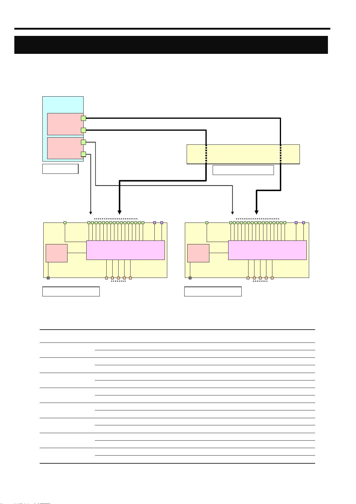
Connection with 1Gb Interlink Expansion Card
Blade Slot number
Port number
of Mezzanine slot 1
Switch Module slot number
Port number of
1Gb Intelligent L2 Switch
1
1 1 9
2 2 9
2
1 1 10
2 2 10
3
1 1 11 2 2
11
4
1 1 12
2 2 12
5
1 1 13 2 2
13
6
1 1 14 2 2
14
7
1 1 15
2 2 15
8
1 1 16
2 2 16
(English)
The following figure shows the network connection diagram with N8406-013 1Gb Interlink Expansion Card. The
ports of Mezzanine slot 1 installed in CPU Blades are connected to Ports 9 - 16 of 1Gb Intelligent L2 Switches
installed in Switch Module slots 1 and 2 of Blade Enclosure (6U) when the 1Gb Interlink Expansion Card is
installed in Switch Module slots 3 and 4.
The following table lists the connections among Blade Slots, ports of Mezzanine slot 1, Switch Module slots, and
ports of 1Gb Intelligent L2 Switches:
34
Page 57

Network Cables
Connector
RJ-45
Type of Cable
UTP/STP twisted-pair cable
Eight wicks, four pairs
Regulation
EIA/TIA standard
10Base-T
Category 3
100Base-TX
Category 5 or higher
1000Base-T
Category 5e or higher
Cable Length
(max.)
100m
The network cables must have the following specifications:
(English)
35
Page 58

Installation Procedure
1
Open the ejector of the 1Gb Intelligent L2
Switch.
Ejector
2
With the ejector open, insert the Switch
Module into the Blade Enclosure.
Blade Enclosure
Ejector
3
Close the ejector to secure the Switch
Module in the Blade Enclosure.
The Switch Module is locked in place.
(English)
Installation
Refer to the Blade Enclosure User’s Guide for details.
36
Page 59

IMPORTANT:
・ The Switch Module is powered by the Blade Enclosure. The Switch
Module is powered on as soon as it is installed in the powered Blade
Enclosure. Therefore, make sure that the ports connected with the
Switch Module are only the ports of the on-board LAN and NIC on the
CPU Blade. Then, install the Switch Module in the Blade Enclosure.
・ Do not hold the ejector to install the Switch Module in the Blade
Enclosure. Hold the Switch Module itself and insert it into the Switch
Module slot. Inserting the Switch Module while holding the ejector
may damage it or cause it to break off from the Switch Module. It may
cause personal injury if the Switch Module falls.
NOTE:
・ The Switch Module does not have a POWER switch.
・ The STATUS LED turns green after 10 seconds from installing the
Switch Module in the powered Blade Enclosure.
Removal Procedure
1
Open the ejector of the 1Gb Intelligent L2
Switch.
Blade Enclosure
2
Pull the ejector slightly.
Ejector
(English)
Refer to the Blade Enclosure User’s Guide for details.
37
Page 60

3
With the ejector open, firmly hold the
Switch Module and slowly pull it out from
the Blade Enclosure.
IMPORTANT:
・ Install the Switch Module in the Blade Enclosure after 30 seconds or
longer from removing it from the powered Blade Enclosure.
・ If the Blade Enclosure is used with the Switch Module removed,
install the Slot Cover to the empty slot and secure it with a screw.
NOTE: For information on how to install the Slot Cover, see the Blade
Enclosure User’s Guide.
(English)
38
Page 61

(English)
Baud rate
9600
Data bits
8
Parity
None
Stop bits
1
Flow control
None
IMPORTANT: A leased line cannot be connected to the Serial Port
directly.
NOTES:
・ The command line interface in L2 switch mode has 2 modes, AOS
CLI and ISCLI. You can set the Switch Module to use either CLI
mode. By default, the mode is AOS CLI.
・ When operating the Switch Module with NEC WebSAM
NetvisorPRO, use L2 switch mode software and ISCLI.
・ The serial interface is not connected between this switch module and
the EM card. Therefore, it is not available to connect from the
Enclosure Manager by using the “CONNECT SWITCH” command on
Blade Enclosure (10U) or the “connectswitch” command on Blade
Enclosure (6U).
Configuration
The Switch Module can be configured locally using the Serial Port or remotely using the Ethernet ports.
Connection via Serial Port
Use a serial cable (with a female DB-9 connector) to connect between a management console (such as a personal
computer) and the Serial Port. Communication software that supports VT100 terminal emulation is required.
Configure the communication software settings as shown in the table below:
Connection via Network
To connect to this Switch Module via a network, you need to assign an IP address to it. You can access the
browser-based interface or the command line interface in the switch through a telnet application or Web browser
by using the assigned IP address.
IP address is configured by the following:
- Assignment by DHCP (default)
- Manual assignment (only in L2 switch mode)
39
Page 62

NOTES:
・ If the IP address cannot be obtained from the DHCP server in L2
switch mode, access the local console of the Switch Module and
assign the IP address manually. Refer to “Manual assignment” below.
After assigning the IP address, access the Switch Module via the
network.
・ Port 19 of the Switch Module is connected with the management
network in the Blade Enclosure.
・ Refer to the Blade Enclosure User’s Guide and the Enclosure
Manager Card User’s Guide to connect or configure the Enclosure
Management LAN port.
>> # /cfg/sys/dhcp disable
>> # /cfg/l3/if 256
>> IP Interface 256# addr 205.21.17.3
Current IP address: 0.0.0.0
New pending IP address: 205.21.17.3
Pending new subnet mask: 255.255.255.0
. . . . . . . . . . . .
>> IP Interface 256# ena
>> IP Interface 256# ../gw 4
>> Default gateway 4# addr 205.21.17.1
>> Default gateway 4# ena
>> Default gateway 4# apply
>> Default gateway 4# save
(Disable dhcp)
(Select IP interface 256)
(Assign IP address for the Interface)
(Enable IP interface 256)
(Select default gateway 4)
(Assign IP address for a router)
(Enable default gateway 4)
(Apply the configuration)
(Save the configuration)
Switch> enable
Switch# configure terminal
Switch(config)# no system dhcp
Switch(config)# interface ip 256
Switch(config-ip-if)# ip address 205.21.17.3 255.255.255.0
Switch(config-ip-if)# enable
Switch(config-ip-if)# exit
Switch(config)# ip gateway 4 address 205.21.17.1
Switch(config)# ip gateway 4 enable
Switch(config)# copy running-config startup-config
(Enter Privileged EXEC mode)
(Enter Global Configuration mode)
(Disable dhcp)
(Enter Interface IP Configuration mode)
(Assign IP address for the Interface)
(Enable IP interface 256)
(Exit to Global Configuration mode)
(Assign default gateway 4)
(Enable default gateway 4)
(Save the configuration)
IMPORTANT:
・ When assigning an IP address and default gateway for the
management interface manually, assign them to interface 256 and
Gateway 4, respectively.
・ When DHCP is enabled in L2 switch mode, the IP address obtained
from the DHCP server overrides the static IP address. When
assigning the IP address manually, disable DHCP.
(English)
- Assignment by DHCP
By default, the management network interface on the Switch Module is set up to obtain its IP address from the
DHCP server on the Enclosure Manager Card. You can configure the IP address in the Enclosure Manager
Card. For more information, see the Enclosure Manager Card User’s Guide.
SmartPanel mode software supports only IP address assignment by DHCP.
- Manual assignment (only in L2 switch mode)
You can assign the IP address by connecting to the Switch Module via the local console. Refer to the following
examples:
AOS CLI
ISCLI
40
Page 63

(English)
>> # /boot/cur
Currently set to boot software image1, factory default config block:
Current FLASH software
image1: version 1.2.0, download 0:15:51 Mon Jan 2, 2006
NormalPanel
image2: version 1.0.0, download 1:32:08 Sun Jan 8, 2006
SmartPanel
boot kernel: version 1.2.0
(Display the current boot options)
>> # /boot/image
Currently there are 2 images on flash:
image1 is for NormalPanel
image2 is for SmartPanel
Currently set to use switch software “image1” on next boot.
Specify new image to use [“image1”/”image2”]: image2
Next boot will use switch software image2 instead of image1.
>> # Boot Options# /boot/reset
WARNING: Image2 is for SmartPanel!
All config regions will be cleared!
The factory config block will be used!
Please backup the active config!
Reset will use software “image2” and the factory default config block.
>> Note that this will RESTART the Spanning Tree,
>> which will likely cause an interruption in network service.
Confirm reset [y/n]: y
(Change the image the switch software
is stored)
(Enter the image to run on next boot)
(Reboot the switch)
(Enter „y‟)
IMPORTANT: When the switch software is changed and the switch is
rebooted, the switch configuration is removed and the switch runs the
factory configuration block. Backup the switch configuration if necessary.
Selecting switch software to run
- Current boot options
To display the current boot options, enter the following:
NormalPanel is the L2 switch mode software, and SmartPanel is the SmartPanel mode software. By default, the
NormalPanel software is stored in image1, and the SmartPanel software is stored in image2.
- Changing the switch software to run
To change the switch software, enter the following:
41
Page 64

User account
Description
Password
(Default)
user
The user can view all the Switch Module status information and statistics,
but cannot make any configuration changes to the Switch Module. The
user account is enabled by default.
user
oper
The operator manages all functions of the Switch Module, but these
changes will be lost when the Switch Module is rebooted or reset. By
default, the operator is disabled and has no password.
-
admin
The administrator has complete access to all menus, information, and
configuration commands on the Switch Module. The admin account is
enabled by default.
admin
NOTE: It is recommended that you change the passwords after initial
configuration.
(English)
User access levels
The Switch Module provides three levels for user access. The default user names/passwords for each access level
are listed in the following table:
42
Page 65

(English)
Troubleshooting
This section describes the actions to take to resolve a problem with the Switch Module. If the Switch Module still
fails to operate normally, contact your service representative.
Unable to insert or remove the Switch Module.
1. Make sure that there is no foreign object inside the Switch Module slot.
2. Make sure that you have installed the Switch Module in the right direction.
The Switch Module does not work.
1. See “Connection with CPU Blade” (page 33) to make sure that the Switch Module, slot for onboard
LAN or mezzanine card, and cable connections are correctly installed in the Blade Enclosure.
2. Make sure that you have properly installed the Switch Module in the Blade Enclosure.
3. Make sure that power is supplied throughout the system, including the Switch Module.
The STATUS LED turns amber, not green.
1. Make sure that the Switch Module has been installed properly.
2. If the STATUS lamp does not turn on when installing the Switch Module, remove the Switch Module
from the Blade Enclosure, and then install it again.
3. When installed in the Blade Enclosure (6U), an error message is displayed on the SIGMABLADE
monitor. Refer to the User’s Guide of the Enclosure Manager Card or contact your service
representative according to the error type indicated.
The local console is disabled.
1. Make sure that the cross cable used for connection is the correct kind.
2. Make sure that the communication parameters for the local console are properly specified.
3. Make sure that power is supplied throughout the system, including the Switch Module.
The remote console is disabled.
1. Make sure that the connection between the Switch Module and the remote console is correct.
2. Make sure that the remote console is properly configured, including an IP address.
3. Make sure that power is supplied throughout the system, including the Switch Module.
Cannot establish a link. (The LINK/ACT LED indicator does not turn on.)
1. Make sure that the cable has been connected properly.
2. See "Network Cables" (page 35) to make sure that your cable meets the required specifications.
3. Make sure that the communication mode of link partners (e.g. switch) is set for Auto Negotiation or
1000Mbps/Full Duplex.
4. Make sure that you are using the correct driver in the CPU Blade.
5. Check the error logs on the link partner side.
Switch Module Reduce Recovered trap is notified by the EM card.
1. When installing the Switch Module in the Blade Enclosure or powering on the Blade Enclosure that
contains the Switch Module while the trap notification is enabled in the EM card, Switch Module
Reduce Recovered trap is notified by the EM card. This does not cause any trouble, and you can
continue operation.
43
Page 66

(English)
Network adapter Teaming feature of the CPU Blade does not work.
1. Once the teaming adapter is removed, make sure that each interface is available.
2. Make sure that the teaming is correctly configured and the network is correctly deployed.
3. Turn off Spanning Tree Protocol on the port connected to the network adapter when using "Adapter
Current date and time are incorrect.
1. This Switch Module does not have a battery to maintain the date and time. The date and time on this
Fault Tolerance" (AFT).
switch is reset when it is rebooted or the blade system is powered off. Set the date and time again
after it is rebooted or configure the NTP client on the switch.
44
Page 67

Product name
1Gb Intelligent L2 Switch
Product code
N8406-022A
(EXP422A)
Interface
1000BASE-X (Port 1-18)
10BASE-T/100BASE-TX (Port 19)
10BASE-T/100BASE-TX/1000BASE-T (Port 20-24)
Connector
RJ-45
Port/Slot
16 ports
2 ports
1 port
5 ports
(for CPU Blade)
(for the same adjacent Switch Module)
(for management)
(for uplink)
Power consumption
25W Max
Environmental requirements
Temperature
10 to 35 ℃
Humidity
20 to 80 % RH (no condensation)
External dimensions
193(W) x 268(D) x 28(H) mm
Weight
1.25 kg
Specification
(English)
45
Page 68

N8406-022A
(EXP422A)
GbE インテリジェントスイッチ(L2)ユーザーズガイド
1Gb Intelligent L2 Switch User’s Guide
2008 年 7 月 (第 1 版)
July 2008 (1st Edition)
日本電気株式会社
NEC Corporation
東京都港区芝 5 丁目 7 番 1 号
TEL(03)3454-1111(大代表)
7-1 Shiba 5-Chome, Minato-Ku
Tokyo 108-8001, Japan
このマニュアルは再生紙を使用しています
This guide is made from recycled paper.
856-126757-003-00
PN# 456-01753-000
456-01753-000
PN# 456-01753-000
Page 69

 Loading...