

Page 1

1
注意
製品のご使用前に、必ず本書をお読みの上で注意をお守り下さい。本書は、必要な時にす
ぐ見られるように保管して下さい。
N8406-017
4G FCスルーカード
ユーザーズガイド
855-900578-A
2007年 11月 4版
PN# 456-01763-000
Page 2

2
注 意
この装置は、情報処理装置等電波障害自主規制協議会(VCCI)の基準に基づくクラスA情報
技術装置です。この装置を家庭環境で使用すると電波妨害を引き起こすことがあります。
この場合には使用者が適切な対策を講ずるよう要求されることがあります。
商標について
ESMPROとDianaScopeは日本電気株式会社の登録商標または商標です。
その他、記載の会社名および商品名は各社の登録商標または商標です。
サンプルアプリケーションで使用している名称は、すべて架空のものです。実在する品名、団体名、個人名とは一切
関係ありません。
ご注意
(1) 本書の内容の一部または全部を無断転載することは禁止されています。
(2) 本書の内容に関しては将来予告なしに変更することがあります。
(3) NECの許可なく複製・改変などを行うことはできません。
(4) 本書は内容について万全を期して作成いたしましたが、万一ご不審な点や誤り、記載もれなどお気づ
きのことがありましたら、お買い求めの販売店にご連絡ください。
(5) 運用した結果の影響については(4)項にかかわらず責任を負いかねますのでご了承ください。
Page 3

3
死亡又は重傷を負う危険性があることを示します。
火傷やけがの危険性があることを示します。
注意の喚起
この記号は危険が発生するおそれがあること
を表します。記号の中の絵表示は危険の内容を
図案化したものです。
(例)
(感電注意)
行為の禁止
この記号は行為の禁止を表します。記号の中や
近くの絵表示は、してはならない行為の内容を
図案化したものです。
(例)
(分解禁止)
行為の強制
この記号は行為の強制を表します。記号の中の
絵表示は、しなければならない行為の内容を図
案化したものです。危険を避けるためにはこの
行為が必要です。
(例)
(プラグを抜
け)
注意
この手引きは、必要なときすぐに参照できるよう、お手元に置いておくようにしてください。
「使用上のご注意」を必ずお読みください。本製品の移設の際は必ず本書も一緒にしてくだ
さい。
使用上のご注意 - 必ずお読みください -
本製品を安全に正しくご使用になるために必要な情報が記載されています。
安全にかかわる表示について
本製品を安全にお使いいただくために、この手引きの指示に従って操作してください。
この手引きには装置のどこが危険か、どのような危険に遭うか、どうすれば危険を避けら
れるかなどについて説明されています。また、装置内で危険が想定される箇所またはその
付近には警告ラベルが貼り付けられています。
手引きおよび警告ラベルでは、危険の程度を表す言葉として、「警告」と「注意」という
用語を使用しています。それぞれの用語は次のような意味を持つものとして定義されてい
ます。
危険に対する注意・表示は次の3種類の記号を使って表しています。それぞれの記号は次
のような意味を持つものとして定義されています。
Page 4

4
指定以外のコンセントに差し込まない
電源は指定された電圧、電源の壁付きコンセントをお使いください。指定以
外の電源を使うと火災や漏電の原因となります。
感電の危険性があることを示
します。
爆発の危険性があることを示し
ます。
指などがはさまれるおそれが
あることを示します。
発煙または発火のおそれがある
ことを示します。
高温による傷害を負うおそれ
があることを示します。
回転物によるけがのおそれがあ
ることを示します。
特定しない一般的な注意・警告
を示します。
機器の分解や改造を禁止する
ことを示します。
水や液体のかかる場所で使用し
ないでください。水に濡らすと感
電や発火のおそれがあります。
ぬれた手で触らないでくださ
い。感電のおそれがあります。
一般的な禁止の通告を示します。
電源プラグをコンセントから
抜くこと、および分電盤のサー
キットブレーカを切ることの
指示を示します。
一般的な使用者の行動の指示を
示します。
(本書での表示例)
注意を促す記号 危険に対する注意の内容 危険の程度を表す用語
本書および警告ラベルで使用する記号とその内容
注意の喚起
行為の禁止
行為の強制
Page 5

5
一般的な注意事項
人命に関わる業務や高度な信頼性を必要とする業務には使用しない
本装置は、医療機器・原子力設備や機器、航空宇宙機器・輸送設備や機器な
ど、人命に関わる設備や機器および高度な信頼性を必要とする設備や機器な
どへの組み込みやこれらの機器の制御などを目的とした使用は意図されてお
りません。これら設備や機器、制御システムなどに本装置を使用した結果、
人身事故、財産損害などが生じても当社はいかなる責任も負いかねます。
自分で分解・修理・改造はしない
本書に記載されている場合を除き、絶対に分解したり、修理・改造を行った
りしないでください。装置が正常に動作しなくなるばかりでなく、感電や火
災の危険があります。
煙や異臭、異音がしたまま使用しない
万一、煙、異臭、異音などが生じた場合は、ただちに電源をOFFにして電源
プラグをコンセントから抜いてください。その後、お買い求めの販売店また
は保守サービス会社にご連絡ください。そのまま使用すると火災の原因とな
ります。
針金や金属片を差し込まない
装置に金属片や針金などの異物を差し込まないでください。火災・感電の危
険があります。
複数のスイッチモジュール/スルーカードを同時に取り付け/取り外し
しない
スイッチモジュール/スルーカードの取り付け/取り外しは、1枚単位で行っ
てください。複数のスイッチモジュール/スルーカードを同時に取り付け/
取り外しをしたり、別のスロットのカバーを取り外したまま取り付け/取り
外しをしたりすると、感電するおそれがあります。
光線を直視しない
本装置に付属のSFPモジュールは、レーザ安全基準クラス1に適合しています
が、近距離(20cm以内)での直視は瞳孔に悪影響を与える恐れがあります。
動作中はSFPモジュールのポートをのぞきこまないでください。また、光フ
ァイバケーブルを接続していない場合は必ず防塵カバー(ゴムキャップ)を
はめ、コネクタ端子を保護してください。
安全上のご注意
安全のために、ここに記載されている注意事項を守ってください。本装置を取り付けるブ
レード収納ユニット(SIGMABLADE-H)には、電源ユニットが搭載されています。感電しな
いように注意してください。
Page 6

6
装置内に水や異物を入れない
装置内に水などの液体、ピンやクリップなどの異物を入れないでください。
火災や感電、故障の原因となります。もし入ってしまったときは、すぐ電源
をOFFにして、ブレード収納ユニットから取り外してください。分解しない
で販売店または保守サービス会社にご連絡ください。
中途半端に取り付けない
インタフェースケーブルは確実に取り付けてください。ブレード収納ユニッ
トには確実に取り付けてください。中途半端に取り付けると接触不良を起こ
し、発煙や発火の原因となるおそれがあります。
指定以外のインタフェースケーブルを使用しない
インタフェースケーブルは、NECが指定するものを使用し、接続する装置や
コネクタを確認した上で接続してください。指定以外のケーブルを使用した
り、接続先を誤ったりすると、ショートにより火災を起こすことがあります。
ペットを近づけない
本装置にペットなどの生き物を近づけないでください。排泄物や体毛が装置
内部に入って火災や感電の原因となります。
近くで携帯電話やPHS、ポケットベルを使わない
本装置のそばでは携帯電話やPHS、ポケットベルの電源をOFFにしておいて
ください。電波による誤動作の原因となります。
Page 7

7
設置・移動・保管に関する注意事項
指定以外の場所に設置しない
本装置を次に示すような場所や本書で指定している場所以外に置かないでく
ださい。火災の原因となるおそれがあります。
● ほこりの多い場所。 ● 給湯器のそばなど湿気の多い場所。
● 直射日光が当たる場所。● 不安定な場所。
腐食性ガスの存在する環境で使用または保管しない
腐食性ガス(二酸化硫黄、硫化水素、二酸化窒素、塩素、アンモニア、オゾン
など)の存在する環境に設置し、使用しないでください。また、ほこりや空気
中に腐食を促進する成分(塩化ナトリウムや硫黄など)や導電性の金属などが
含まれている環境へも設置しないでください。装置内部のプリント板が腐食
し、故障および発煙・発火の原因となるおそれがあります。もしご使用の環
境で上記の疑いがある場合は、販売店または保守サービス会社にご相談くだ
さい。
通気口をふさがない
ブレード収納ユニットにある通気口をふさがないでください。ブレード収納
ユニットに搭載した機器の内部の温度が上がり、火災の原因となるおそれが
あります。
故障時の処置
故障時の処置
故障した場合は、分電盤のブレーカを切断し、または電源プラグをコンセン
トから抜き、保守員にご連絡下さい。
廃棄に関する注意事項
装置の廃棄/回収リサイクル
装置の廃棄、回収又はリサイクル時は事前に当社営業にご連絡願います。
Page 8

8
お手入れ・内蔵機器の取り扱いに関する注意事項
ブレード収納ユニット内部に手を入れない
ブレード収納ユニットに装置を取り付け/取り外しをする際には、ブレード
収納ユニット内に手を入れないでください。感電するおそれがあります。ま
た、ブレード収納ユニットに取り付けられているカバーは装置の取り付けな
ど必要な場合を除いて取り外さないでください。装置の取り付け/取り外し
は1台ずつ行ってください。
ブレード収納ユニットに取り付けたまま取り扱わない
お手入れをする場合は、ブレード収納ユニットから取り外してから行ってく
ださい。たとえ電源をOFFにしても、ブレード収納ユニットに接続したまま
作業するとブレード収納ユニットに搭載されている機器が正常に動作しなく
なるばかりか感電や火災の原因となるおそれがあります。
また、電源プラグはときどき抜いて、乾いた布でほこりやゴミをよくふき取
ってください。ほこりがたまったままで、水滴などが付くと発熱し、火災の
原因となるおそれがあります。
Page 9

9
保守サービスについて
本製品の保守に関して専門的な知識を持つ保守員による診断・保守サービスを用意してい
ます。
本製品をいつまでもよい状態でお使いになるためにも、保守サービス会社と保守サービス
を契約されることをお勧めします。
取り扱い上のご注意 - 装置を正しく動作させるために
本装置を正しく動作させるために次に示す注意事項をお守りください。これらの注意を無
視した取り扱いをすると装置の誤動作や故障の原因となります。
● スイッチモジュール/スルーカード
- 本装置は近接制限区域に設置してください。
- 本装置を取り付けることができるブレード収納ユニットに搭載してください。
- スイッチモジュール/スルーカードはブレード収納ユニットに必ず正しく取り付
け直してください。
- 落雷等が原因で瞬間的に電圧が低下することがあります。この対策として無停電電
源装置等を使用することをお勧めします。
● オプションの増設電源およびその他電子部品
- これらの製品は大変静電気に弱い電子部品です。身体の静電気を逃がしてから製品
を取り扱ってください。また、製品の端子部分や部品を素手で触ったり、製品を直
接机の上に置いたりしないでください。
- オプションは購入したスイッチモジュール/スルーカードのオプション対象品で
あることを確認してください。たとえ装置に取り付け/接続できても正常に動作し
ないばかりか、装置本体が故障することがあります。
- オプションはNECの純正品をお使いになることをお勧めします。他社製のオプショ
ンには本装置に対応したものもありますが、これらの製品が原因となって起きた故
障や破損については保証期間中でも有償修理となります。
Page 10

10
目 次
使用上のご注意 - 必ずお読みください - ................... 3
安全にかかわる表示について ........................... 3
本書および警告ラベルで使用する
記号とその内容 ................................................ 4
安全上のご注意 ................................................ 5
一般的な注意事項 ................................. 5
設置・移動・保管に関する注意事項 .... 7
故障時の処置 ........................................ 7
廃棄に関する注意事項 .......................... 7
お手入れ・内蔵機器の
取り扱いに関する注意事項 ................... 8
取り扱い上のご注意
- 装置を正しく動作させるために - .............. 9
まえがき ..................................................................... 11
装置概要 ..................................................................... 11
添付品の確認 .............................................................. 11
各部の名称.................................................................. 12
FCコネクタ......................................... 27
緊急電源遮断(EPO) .................................................... 29
コマンドラインインタフェース(CLI) (EMカード) ..... 30
初期設定 ......................................................... 30
ユーザに対する
モジュールアクセス権の設定(EMカー
ド) ....................................................... 30
動作状態の確認 .............................................. 31
スイッチモジュール/スルーカード .. 31
モジュールの交換 ....................................................... 33
スイッチモジュール/スルーカード .............. 33
コマンド一覧 .............................................................. 36
コマンド一覧 .................................................. 36
コマンド仕様 .............................................................. 38
スイッチモジュール管理コマンド .................. 38
スイッチモジュールの電源OFF .......... 38
スイッチモジュールの電源ON ........... 38
装置前面 ......................................................... 12
設 置 ......................................................................... 13
構成品の確認 .................................................. 13
ブレード収納ユニットへの取り付け .............. 13
取り付け手順 ...................................... 17
取り外し手順 ...................................... 20
SFPモジュールの取り付け ............................. 21
電源のON/OFF ........................................................... 24
スイッチモジュール/スルーカードの
電源ON/OFF ................................................... 24
ブレード収納ユニットからの電源ON . 24
ネットワーク・シリアル(COM)ポートか
らの
電源ON/OFF ....................................... 24
ケーブルの接続 .......................................................... 27
前面 ................................................................ 27
スイッチモジュールの再起動 ............. 39
スイッチモジュール
のUser Assigned Nameの設定 .......... 39
スイッチモジュールのIDランプの制御40
スイッチモジュール情報の表示 .......... 40
スイッチモジュール一覧の表示 .......... 41
スイッチモジュール
マップ情報(E-Keying情報)の表示 ..... 42
スイッチモジュール ステータスの表示 4
4
異常時の処置 .............................................................. 46
電源 ................................................................ 46
廃 棄 ......................................................................... 47
第三者への譲渡について ............................................ 47
仕 様 ......................................................................... 47
Page 11

まえがき
装置概要
添付品の確認
品名
数量
備考
1
4G FCスルーカード
1
SFPモジュール(FCコネク
タ用防塵カバー付き)全数
(16個)取り付け済み
2
防塵カバー
8
通信ポート用
3
ユーザーズガイド
1
本書
4
保証書
1
日本国内のみ有効
添付品はセットアップをするときやオプションの増設、製品が故障したとき
に必要となりますので大切に保管してください。
この度は、N8406-017 4G FCスルーカードをお買い上げいただき誠にありがとうござい
ます。
本装置はブレード収納ユニット(SIGMABLADE-H)に搭載することにより、各CPUブレード
に取り付けたブレード用メザニンカード(FibreChannelコントローラ)を外部接続する機能
を実現させます。
本装置をご使用になる前に、必ず本書をお読みください。なお、SIGMABLADEシリーズ
に添付の「ユーザーズガイド」または「スタートアップガイド」も併せて参照してくださ
い。
本装置は、ブレード収納ユニットに搭載される最大で16台のCPUブレードと接続すること
により、各CPUブレードのメザニン拡張スロットに搭載したブレード用メザニンカード(F
ibreChannelコントローラ)のポートを外部接続することができます。
製品が入った梱包箱の中には、本体以外にいろいろな添付品が入っています。以下の構成
品表を参照してすべてがそろっていることを確認し、それぞれ点検してください。万一足
りないものや損傷しているものがある場合は、販売店に連絡してください。
11
Page 12

各部の名称
① 通信ポート
上段左からポート13~ポート16。
下段左からポート1~ポート12。
② イジェクタ
このイジェクタを手前に引くことで本装置を
ブレード収納ユニットから取り外すことがで
きる。
③ IDランプ(青色)
スイッチモジュール/スルーカードの筐体識
別に使用する。
④ STATUSランプ(緑色/アンバー色)
正常状態の場合は緑色に点灯する。異常の場合
はアンバー色に点灯する。
⑤ LINK/ACTランプ(緑色)
通信ポートがネットワークに接続されている
場合は緑色に点灯する。
ID
1
1-4 5-8
9-12
13-16
2 3 4 5 6 7 8 9 10 11 12 13 14 15 16
③ ④ ① ② ⑤
本装置の各部の名称を次に示します。
装置前面
12
Page 13

設 置
● 本装置を取り付けることのできるブレード収納ユニットはブレード収納ユニット
(SIGMABLADE-H)です。
● スイッチモジュール/スルーカードは種類および組合せによって搭載可能なスイッ
チモジュールスロットが異なりますので、注意してください。
● ブレード収納ユニットのユーザーズガイドを参照して、適切なスロットに本製品を
取り付けてください。本製品以外に取り付けるスイッチモジュール/スルーカード
がある場合は、スイッチモジュール/スルーカードの種類および組合せによって、
本製品を取り付けるスロットが異なります。(他のモジュールのユーザーズガイドも
併せてご覧ください。)
● スイッチモジュールスロットに取り付けることのできるブランクパネルについて
スロット
スロット
スロット
スロット
スロット
スロット
スロット
スロット
ID
1
1-4 5-8
9-12
13-16
2 3 4 5 6 7 8 9 10 1112 13 14 15 16
ID
1
1-4 5-8
9-12
13-16
2 3 4 5 6 7 8 9 10 1112 13 14 15 16
ID
1
1-4 5-8
9-12
13-16
2 3 4 5 6 7 8 9 10 1112 13 14 15 16
ID
1
1-4 5-8
9-12
13-16
2 3 4 5 6 7 8 9 10 1112 13 14 15 16
ID
1
1-4 5-8
9-12
13-16
2 3 4 5 6 7 8 9 10 1112 13 14 15 16
ID
1
1-4 5-8
9-12
13-16
2 3 4 5 6 7 8 9 10 1112 13 14 15 16
構成品の確認
11ページの構成品表で、構成品がそろっていることを確認してください。
ブレード収納ユニットへの取り付け
ブレード収納ユニット(SIGMABLADE-H)の搭載スロットの位置については下図のとおり
です。
搭載スロットへはブレード収納ユニットのユーザーズガイドを参照して、適切な位置に本
装置を取り付けてください。スイッチモジュール/スルーカードを搭載しないスロットに
はブランクパネルを取り付けてください。
13
Page 14

は、ブレード収納ユニットのユーザーズガイドを参照してください。
14
Page 15

● メザニン拡張スロットを利用して本装置をCPUブレードに接続する場合は、使用す
るメザニン拡張スロット数に応じた枚数のブレード用メザニンカードを準備してく
ださい。(詳しくは、ブレード収納ユニットのユーザーズガイドを参照してください。)
● 1枚のブレード用メザニンカード(FibreChannelコントローラ)で2ポート使用する場
合は、本装置が2台必要です
● FCケーブルの接続には本装置に添付または指定のSFPモジュールが必要です。 (搭
載するスイッチ/スルーカードの種類によって搭載可能なSFPモジュールは異なり
ますのでご注意ください。)
● 本製品は4Gbpsまたは2Gbps用です。1Gbps製品を接続しないよう注意願います。
4G FCスルーカードとFibreChannelコントローラ間のFCコネクタ接続
最大16台
FC
コ
ン
ト
ロ
ー
ラ
FCポート(16ポート)
・・・
CPUブレード
ブレード収納ユニット(SIGMABLADE-H)
FCポート(16ポート)
2/4Gbps
4G FCスルーカード1
4G FCスルーカード2
※本装置の通信ポート1~16は、それぞれブレード収納ユニットのブレードスロッ
ト1~16に搭載されたCPUブレードのブレード用メザニンカード(FibreChannel
コントローラ)に対応します。本装置の通信ポートについては「各部の名称」を、
Port1
Port2
FC
コ
ン
ト
ロ
ー
ラ
FC
コ
ン
ト
ロ
ー
ラ
FC
コ
ン
ト
ロ
ー
ラ
Port1
Port2
Port1
Port2
Port1
Port2
15
Page 16

16
Page 17

取り付け手順
装置を安全にお使いいただくために次の注意事項を必ずお守りください。人
が死亡する、または重傷を負うおそれがあります。詳しくは、3ページ以降の
説明をご覧ください。
● 複数のスイッチモジュール/スルーカードを同時に取り付け/取り外し
しない
● ブレード収納ユニット内部に手を入れない
ブレード収納ユニットをラックから取り出して、CPUブレード、スイッチモ
ジュール、スルーカード、またはその他のオプションを取り付けたりしない
でください。
● 取り外したブランクパネルは大切に保管しておいてください。
● 取り付けるスロット以外のブランクパネルを取り外さないでください。
①
②
ブレード収納ユニットに本装置を取り付けます。本装置はブレード収納ユニットの電源が
ONの状態(他のスロットのCPUブレードおよびスイッチモジュール/スルーカードが動作
している状態)でも取り付け/取り外しができます。(取り付けの一例を示します。他のス
ロットへも同様の手順で取り付けられます。)
1. 「ブレード収納ユニットへの取り付け」(13ページ)を参照して、取り付けるスロットを
確認する。
2. 取り付けるスロットにブランクパネルが取り付けられている場合は、上部のイジェクタ
を引き、 ブランクパネルを取り外す。
3. 本装置をほこりのない、丈夫で平ら
な机の上に静かに置き、イジェクタ
を開けた状態にする。(イジェクタ
を開ける際は、イジェクタを固定し
ているストッパを右に押しながら
開けてください。)
17
Page 18

18
Page 19

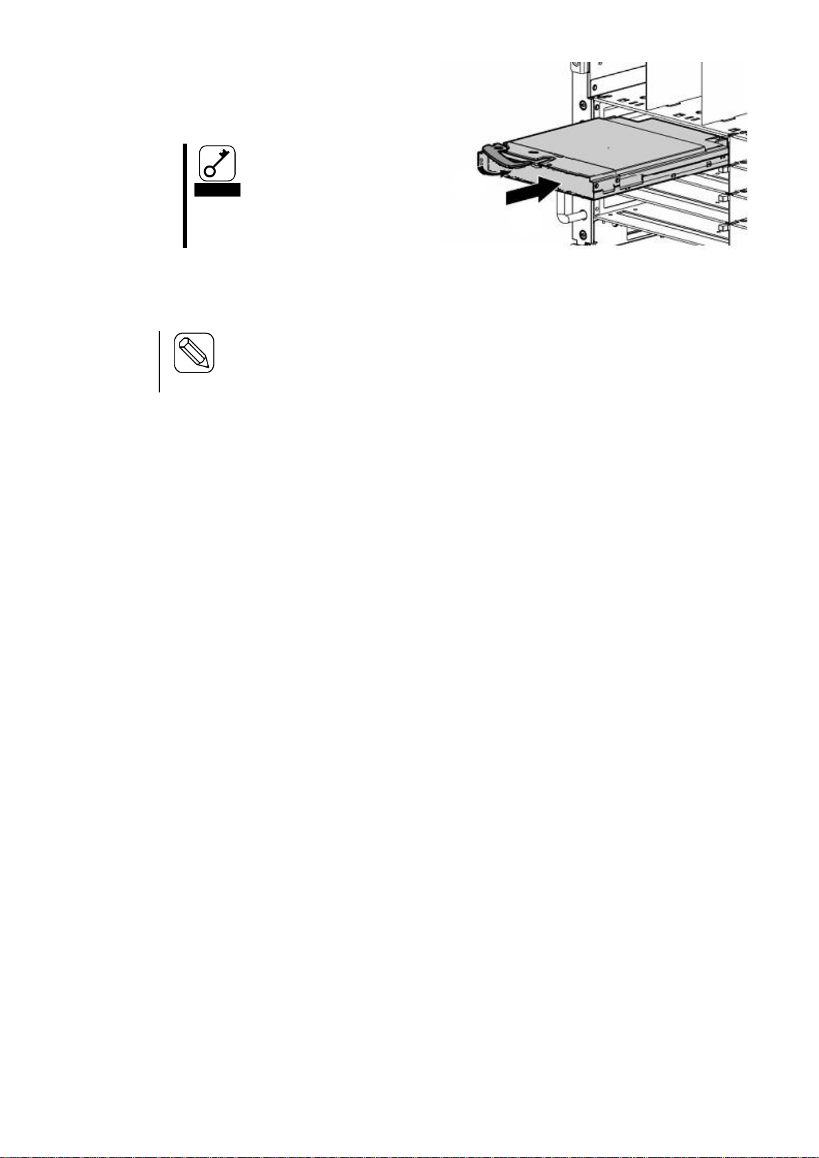
イジェクタを持たないでください。
イジェクタが曲がって装置が破損し
てしまうおそれがあります。
装置前面をゆっくりとていねいに押し、ブレード収納ユニットの奥まで差し込まれるとイ
ジェクタが少し閉じます。そこまでゆっくりと押してください。
①
②
4. 本装置のイジェクタ面を上にして装置
左右をしっかりと持ち、ゆっくりとて
いねいにブレード収納ユニットに半
分(約20cm)ほど差し込む。
5. イジェクタを完全に開いた状態にして、装置前面のフレーム部分を指で押し、ブレード
収納ユニットの奥まで装置をゆっくりとていねいに差し込む。
6. イジェクタをゆっくりと閉じる。
本装置のミッドプレーンコネクタがブレード収納ユニットのミッドプレーンコネクタ
に接続されます。
イジェクタをうまく閉じることができない場合は、ストッパ部分の状態を確認してく
ださい。
正しく引っかかっていない状態でイジェクタを閉じるとイジェクタやブレード収納ユ
ニットを破損するおそれがあります。
以上で完了です。
19
Page 20

取り外し手順
イジェクタは止まるまで完
全に開いてください。
イジェクタ部分を持って取り外さな
いでください。イジェクタが外れて装
置を落下させたり、イジェクタが曲が
って装置が破損してしまうおそれが
あります。
①
②
本装置の取り外しは、次のとおりです。
1. 本装置にインタフェースケーブルが接続されている場合は、すべてのケーブルを取り外
す。
2. イジェクタを開く。(イジェクタを開け
る際は、イジェクタを固定しているスト
ッパ を右に 押しな がら開けて くださ
い。)
3. イジェクタを持って装置のフレームの
左右を手で持てるくらい(約10cm)まで
ブレード収納ユニットから引き出す。
重
4. 装置のフレームの左右をしっかりと持って、ブレード収納ユニットから取り出す。
本装置を取り外したまま運用する場合は、ブランクパネルを取り付けてください。
5. 本装置のイジェクタを閉じる。
以上で完了です。
20
Page 21

装置を安全にお使いいただくために次の注意事項を必ずお守りください。人
が死亡する、または重傷を負うおそれがあります。詳しくは、3ページ以降の
説明をご覧ください。
● 光線を直視しない
本装置に添付のSFPモジュールは、レーザ安全基準クラス1に適合してい
ますが、近距離(20cm以内)での直視は瞳孔に悪影響を与える恐れがあ
ります。動作中はSFPモジュールのポートをのぞきこまないでください。
また、光ファイバケーブルを接続していない場合は必ず防塵カバー(ゴム
キャップ)をはめ、コネクタ端子保護してください。
本装置に添付または指定製品以外のSFPモジュールはご利用になれません。
N8406-017
SFPモジュール
通信ポート
SFPモジュールの取り付け
取り付け手順
SFPモジュールの本製品への実装時は通信ポートの奥まで差し込んでください。
21
Page 22

22
Page 23

SFPモジュール取外し時は必ずレバーを下ろし作業を実施してくださ
い。レバーを下げずにSFPモジュールを引き抜いた場合、SFPモジュー
ルの破損、通信ポートの破損等が発生する場合があります。
光ファイバケーブルの取り付けについては、ケーブルフォーミングや取
り扱う上での専門知識が必要です。専門知識を持った方が行ってくださ
い。
N8406-017
4G FCスルーカード
SFPモジュール
N8406-017
4G FCスルーカード
取り外し手順
SFPモジュールのレバー(引き抜き金具)を下ろしてください。
レバーをつまんで図中の矢印方向に引き抜いてください。
23
Page 24

電源のON/OFF
ブレード収納ユニットからの電源ON
ネットワーク・シリアル(COM)ポートからの電源ON/OFF
CLIによるスイッチモジュール/スルーカードの電源ON/OFF
は”Administrator”またはアクセス権がADMINISTRATORかOPERATOR
であるユーザで行ってください。
スイッチモジュール/スルーカードの電源ON/OFF
ブレード収納ユニットに搭載されているスイッチモジュール/スルーカードの電源のON/
OFFには次の2つの方法があります。ビデオモニタおよび接続している周辺機器をONにし
てからそれぞれの方法で電源をONにしてください。スイッチモジュール/スルーカード
の電源ON後の動作・確認等は「コマンドラインインタフェース」の「動作状態の確認」
を参照してください。
ラックの電源ONによりブレード収納ユニットに電源の供給が始まると、自動的にブレー
ド収納ユニットに搭載されているスイッチモジュール/スルーカードの電源がONになり
ます。また、ブレード収納ユニットに電源が供給された状態でスイッチモジュール/スル
ーカードの交換を行った場合も、スイッチモジュール/スルーカードの交換後、自動的に
スイッチモジュール/スルーカードの電源がONになります。(ブレード収納ユニットの電
源ONの方法はブレード収納ユニットのユーザーズガイドを参照してください。)
ブレード収納ユニットに搭載されているスイッチモジュール/スルーカードの電源のON/
OFFは、ネットワークおよびシリアル(COM)ポートから行うことができます。
ここでは、EMシリアルコンソールおよびEMコンソールからのCLIによるCPUブレードの
電源ON/OFFの方法を示します。CLIについての詳しくは「コマンドラインインタフェース」
および「コマンド入力仕様」を参照してください。EMシリアルコンソールおよびEMコン
ソールについてはブレード収納ユニットのユーザーズガイドを参照してください。
24
Page 25

CLIからのスイッチモジュール/スルーカードの電源ONの方法は以下のとおりです。
1. EMカードの電源がONになっていることを確認する。
2. EMシリアルコンソールまたはEMコンソールのCLIから”Administrator”またはアクセス
権がADMINISTRATORかOPERATORであるユーザでログインしていることを確認す
る。(ログインしていない場合は、”Administrator”またはアクセス権がADMINISTRATO
RかOPERATORであるユーザでログインしてください。)
3. CLIより以下のコマンドを実行する。(詳しくは「コマンド仕様」を参照してください。)
― 電源投入
指定したスイッチモジュール/スルーカードの電源を投入する。
POWERON SWITCH <スロット番号>
以上で完了です。
CLIからのスイッチモジュール/スルーカードの電源OFFの方法は以下のとおりです。
1. EMカードの電源がONになっていることを確認する。
2. EMシリアルコンソールまたはEMコンソールのCLIから”Administrator”またはアクセス
権がADMINISTRATORかOPERATORであるユーザでログインしていることを確認す
る。(ログインしていない場合は、”Administrator”またはアクセス権がADMINISTRATO
RかOPERATORであるユーザでログインしてください。)
3. CLIより以下のコマンドを実行する。(詳しくは「コマンド仕様」を参照してください。)
―電源切断
指定したスイッチモジュール/スルーカードの電源を切断する。
POWEROFF SWITCH <スロット番号>
以上で完了です。
25
Page 26

また、CLIからのスイッチモジュール/スルーカードの再起動の方法は以下のとおりです。
1. EMカードの電源がONになっていることを確認する。
2. EMシリアルコンソールまたはEMコンソールのCLIから”Administrator”またはアクセス
権がADMINISTRATORかOPERATORであるユーザでログインしていることを確認す
る。(ログインしていない場合は、”Administrator”またはアクセス権がADMINISTRATO
RかOPERATORであるユーザでログインしてください。)
3. CLIより以下のコマンドを実行する。(詳しくは「コマンド仕様」を参照してください。)
― スイッチモジュール・スルーカードの再起動
指定したスイッチモジュール/スルーカードを再起動する。
RESTART SWITCH <スロット番号>
以上で完了です。
26
Page 27

ケーブルの接続
本製品は4Gbpsまたは2Gbps用です。1Gbps製品を接続しないよう注意願い
ます。
FCコネクタ
ブレード収納ユニッ
ESMPRO/S
DianaScopeMg
ID
1
1-4 5-8
9-12
13-16
2 3 4 56 7 8 910 1112 131415 16
iStorage
(FCスイッチ)
PC
ID
1
1-4 5-8
9-12
13-16
2 3 4 5 6 78 9 10 1112 1314 1516
前面
本装置の通信ポートに搭載したSFPモジュールのFCコネクタにFCケーブルを接続し、iSt
orage等のストレージ装置を接続することができます。詳しくは接続装置の説明書等を参
照してください。
27
Page 28

光ファイバケーブルの取り付けについては、ケーブルフォーミングや取
り扱う上での専門知識が必要です。専門知識を持った方が行ってくださ
い。
光ファイバケーブルは慎重かつ丁寧に扱うよう注意してください。
光ファイバケーブルの曲げ半径は「最低でも50mm」は確保してくださ
い。
ケーブルのコネクタは無理に押し込まないでください、各コネクタは正
しい向き、正しい角度で差し込まないと接続できません。
正しく差し込んだ時は強い力を入れなくてもスムーズに差し込めるよう
になっています。うまく差し込めないときには無理矢理差し込まずにも
う一度コネクタの向きを確認してください。
ケーブル装着時にコネクタ及びコンタクトに座曲等の損傷、ゴミの付着、
汚れのないことを確認してください。
誤配線のないようにケーブルの仕様と接続先のコネクタを確認してくだ
さい。
コネクタを床などに落下させ破損させないように取り扱いに注意してく
ださい。また、コネクタを床上に引きずりゴミなどを付着させないよう
にしてください。
ケーブルを装着した状態で、コネクタ部やケーブル部に無理な力を掛け
ないでください。また、ケーブルを踏んだり、重いものを載せたりして
変形させないでください。
強く押し込むと光ファイバケーブル端面に傷が付いて光の出力が低下
し、動作不良の原因となることがあります。
SFPポートをお使いになる場合
以下の点にご注意ください。
28
Page 29

緊急電源遮断(EPO)
環境異常(火災・地震)の発生時、コンピュータの入力電源、無停電電源装置(UPS)の電源、
空調機などの電源を緊急電源遮断(EPO:Emergency Power Off)させ、二次災害を防ぐ必要
があります。装置の電源を緊急に遮断する必要があるような危険が生じた場合には、ブレ
ード収納ユニットのユーザーズガイドを参照してEPOを行ってください。
なお、EPOを行った場合、データが壊れる場合があります。したがって、どのような場合
にEPOを行うかを明確に定め、その条件や作業内容を周知徹底して運用してください。
29
Page 30

コマンドラインインタフェース(CLI) (EMカード)
ユーザに対するモジュールアクセス権の設定(EMカード)
EMカードのコマンドラインインタフェース(CLI)により、ブレード収納ユニットに搭載さ
れているCPUブレードやスイッチモジュールなどの搭載モジュールおよびネットワーク
の設定・管理等を行うことができます。
CLIはEMシリアルコンソールおよびEMコンソールから利用できます。CLI、EMシリアル
コンソールおよびEMコンソールについては、ブレード収納ユニットのユーザーズガイド
を参照してください。
初期設定
EMシリアルコンソールまたはEMコンソールから、ブレード収納ユニットに搭載されたス
イッチモジュール/スルーカードの初期設定を行います。設定方法はブレード収納ユニッ
トのユーザーズガイドを参照してください。(「ユーザに対するアクセス権の設定」、「E
Mカードの設定確認およびバックアップ・リストア(EMカード)」
1. EMカードの電源がONになっていることを確認する。
2. EMシリアルコンソールまたはEMコンソールのCLIから”Administrator”またはアクセス
権がADMINISTRATORかOPERATORであるユーザでログインしていることを確認す
る。(ログインしていない場合は、”Administrator”またはアクセス権がADMINISTRATOR
かOPERATORであるユーザでログインしてください。)
3. CLIよりコマンドを実行して以下の項目を設定する。(詳しくはブレード収納ユニットの
ユーザーズガイドの「コマンド仕様」を参照してください。)
― モジュールへのアクセス権の設定(強く推奨)
ユーザのスイッチモジュール/スルーカードへのアクセス権を設定する。
(あらかじめ、設定する対象モジュールのスロット番号を確認してください)
ASSIGN SWITCH [<スロット番号> | <スロット番号> - <スロット番号> |
<スロット番号> , <スロット番号> | ALL] <ユーザ名>
<スロット番号>と<スロット番号>を’-‘(ハイフン)または‘,‘(カンマ)で連結する場
合、’-‘(ハイフン)または‘,‘(カンマ)の前後にスペースを挿入すること。
30
Page 31

スイッチモジュール/スルーカード
4. CLIより以下のコマンドを実行して設定項目が反映されていることを確認する。
設定したユーザからモジュールのIDランプのON/OFF操作を行う。(操作は「コマ
ンド一覧」を参照してください。)
― モジュールのIDランプのON/OFF
ユーザのスイッチモジュール/スルーカードのIDランプのON/OFFを行う。
(あらかじめ、設定する対象モジュールのスロット番号を確認してください)
SET SWITCH UID <スロット番号> [ON | OFF]
以上で完了です。
動作状態の確認
ブレード収納ユニットおよびブレード収納ユニットに搭載されるモジュールの動作状態
を確認します。動作状態の確認はEMシリアルコンソールまたはEMコンソールのCLIから
行います。
1. EMカードの電源がONになっていることを確認する。
2. EMシリアルコンソールまたはEMコンソールのCLIにログインしていることを確
認する。(ログインしていない場合はログインしてください。)
3. CLIより以下のコマンドを実行する。(詳しくは「コマンド仕様」を参照してくださ
い。)
― スイッチモジュール各種ステータスの確認
スイッチモジュールの各種ステータスを確認する。
SHOW SWITCH STATUS
「Failed」の表示がある場合は該当モジュールが適切なスロットに取り付けられ
ていることを確認してください。適切なスロットに取り付けられている場合は、
該当モジュールを再起動してください。再起動しても症状が改善されない場合は
該当モジュールを交換してください。
31
Page 32

以上で完了です。
32
Page 33

モジュールの交換
装置を安全にお使いいただくために次の注意事項を必ずお守りください。人
が死亡する、または重傷を負うおそれがあります。詳しくは、3ページ以降の
説明をご覧ください。
● 複数のCPUブレード、スイッチモジュール/スルーカード、EMカード、
FANユニット、電源ユニット、またはその他モジュールを同時に交換しな
い
● ブレード収納ユニット内部に手を入れない
● スイッチモジュール/スルーカード交換の際は、交換するスイッチモジュール/
スルーカードを経由した通信は行えません。
● ブレード収納ユニットの電源がONの状態でスイッチモジュール/スルーカード
を交換する場合は、すみやかに行ってください。スイッチモジュール/スルーカー
ドを取り外したままの状態にしておくと冷却効率が低下するため、スイッチモジュ
ール/スルーカードまたはスイッチモジュールブランクパネルを取り付けてくだ
さい。
スイッチモジュール/スルーカード
スイッチモジュール/スルーカードを交換します。スイッチモジュール/スルーカードは
ブレード収納ユニットの電源がONの状態(他のスロットのCPUブレードおよびスイッチモ
ジュール/スルーカードが動作している状態)でも交換することができます。
1. 交換するスイッチモジュール/スルーカードを確認する。
2. 交換するスイッチモジュール/スルーカードに接続されているケーブルをすべて外
す。
3. 交換するスイッチモジュールスロットのスイッチモジュール/スルーカードを取り
外す。(スイッチモジュール/スルーカードの取り外し方は「スイッチモジュール/ス
ルーカード」を参照してください。)
33
Page 34

4. 交換するスイッチモジュールスロットに本装置を取り付ける。(本装置の取り付け方は
「取り付け手順」を参照してください。)
取り付けた後自動で電源がONにならない場合は、以下のコマンドを実行して本装置
の電源をONにする。
(1) EMカードの電源がONになっていることを確認する。
(2) EMシリアルコンソールまたはEMコンソールのCLIから”Administrator”またはア
クセス権がADMINISTRATORかOPERATORであるユーザでログインしている
ことを確認する。(ログインしていない場合は、”Administrator”またはアクセス権
がADMINISTRATORかOPERATORであるユーザでログインしてください。)
(3) CLIより以下のコマンドを実行する。(詳しくは「コマンド仕様」を参照してくだ
さい。)
― 電源投入
指定したスイッチモジュール/スルーカードの電源を投入する。
POWERON SWITCH <スロット番号>
5. スイッチモジュール/スルーカードのSTATUSランプが正常(緑色点灯)であることを
確認する。
以上で完了です。
34
Page 35

~ Memo ~
35
Page 36

コマンド一覧
コマンド
アクセ
ス権
説明
初期値
EMカード
の
アクティブ
/
スタンバイ
バッ
クア
ップ
対象
備考
スイッチモジュール管理コマンド
POWEROFF
SWITCH
A/O
指定したスイッチモジュールのD
C電源を切断(OFF)する。
N/A
A
-
POWERON
SWITCH
A/O
指定したスイッチモジュールのD
C電源を投入(ON)する。
N/A
A
-
RESTART
SWITCH
A/O
指定したスイッチモジュールを
再起動する。
N/A
A
-
SET SWITCH
NAME
A/O
指定したスイッチモジュールに
名称をつける。
(スイッチモジ
ュールに依存)
A
-
SET SWITCH
UID
A/O/U
指定したスイッチモジュールのI
Dランプを点灯・消灯する。
N/A
A
-
SHOW SWITCH
INFO
A/O/U
指定したスイッチモジュールの
情報を表示する。
N/A
A
-
コマンド一覧
SIGMABLADE-H EM ファームウェアでサポートする CLI コマンドの一覧を下表に示す。
「アクセス権」の意味
A: Administrator による操作が可能であることを意味する。
O: Operator による操作が可能であることを意味する。
U: User による操作が可能であることを意味する。
「EM カードのアクティブ/スタンバイ」の意味
A:アクティブ EM(現用系)からの設定が可能であることを意味する。
S:スタンバイ EM(待機系)からの設定が可能であることを意味する。
「バックアップ対象」の意味
○:Config 情報でのバックアップ対象であることを意味する。
-:Config 情報でのバックアップ対象でないことを意味する。
SIGMABLADE-H EMファームウェア CLIコマンド一覧
36
Page 37

コマンド
アクセ
ス権
説明
初期値
EMカード
の
アクティブ
/
スタンバイ
バッ
クア
ップ
対象
備考
表示項目:
スイッチモジュールタイプ
製造者名
製品名
製品パーツ番号
製品バージョン
製品シリアル番号
SHOW SWITCH
LIST
A/O/U
搭載されているスイッチモジュ
ールの一覧を表示する。
N/A
A
-
SHOW SWITCH
PORT MAP
A/O/U
指定されたスイッチモジュール
のポートマッピング情報(E-Keyi
ng情報)を表示する。
N/A
A
-
SHOW SWITCH
STATUS
A/O/U
スイッチモジュールの稼動ステ
ータスを表示する。
表示項目:
IDランプ状態
稼動ステータス
N/A
A
-
※ 「表示項目」は表示される主要な項目を記載したものです。
37
Page 38

コマンド仕様
スイッチモジュールの電源OFF
スイッチモジュールの電源ON
スイッチモジュール管理コマンド
※ 「表示項目」は表示される主要な項目を記載したものです。
概要
指定したスイッチモジュールの DC 電源を切断(OFF)する。
コマンド名
POWEROFF SWITCH
引数
<スイッチモジュール番号> | <スイッチモジュール番号> - <スイッチモジュール番号> |
<スイッチモジュール番号> , <スイッチモジュール番号> | "ALL"
<スイッチモジュール番号>と<スイッチモジュール番号>を’-‘(ハイフン)または‘,‘(カンマ)で
連結する場合、’-‘(ハイフン)または‘,‘(カンマ)の前後にスペースを挿入すること。
実行例
1Z34AB7890(Administrator)> poweroff switch 1
Powering off switch module 1.
1Z34AB7890(Administrator)>
スイッチモジュール電源OFFコマンド実行例
初期値
補足
概要
指定したスイッチモジュールの DC 電源を投入(ON)する。
コマンド名
POWERON SWITCH
引数
<スイッチモジュール番号> | <スイッチモジュール番号> - <スイッチモジュール番号> |
<スイッチモジュール番号> , <スイッチモジュール番号> | "ALL"
<スイッチモジュール番号>と<スイッチモジュール番号>を’-‘(ハイフン)または‘,‘(カンマ)で
連結する場合、’-‘(ハイフン)または‘,‘(カンマ)の前後にスペースを挿入すること。
38
Page 39

スイッチモジュールの再起動
スイッチモジュールのUser Assigned Nameの設定
実行例
1Z34AB7890(Administrator)> poweron switch 1
Powering on switch module 1.
1Z34AB7890(Administrator)>
スイッチモジュール電源ONコマンド実行例
初期値
補足
概要
指定したスイッチモジュールを再起動する。
コマンド名
RESTART SWITCH
引数
<スイッチモジュール番号>
実行例
1Z34AB7890(Administrator)> restart switch 4
Entering anything other than 'YES' will result in the command not executing.
Are you sure you want to restart the Switch Module? YES
Resetting Switch Module in slot 4.
1Z34AB7890(Administrator)>
スイッチモジュール再起動コマンド実行例
初期値
補足
画面の指示に従って"YES"の文字を入力すること。
概要
指定したスイッチモジュールに固有の名称をつける。
コマンド名
SET SWITCH NAME
第一引数
<スイッチモジュール番号>
39
Page 40

スイッチモジュールのIDランプの制御
スイッチモジュール情報の表示
第二引数
<User Assigned NAME>
32 文字以内の半角英数字と一部記号で指定する。
実行例
1Z34AB7890(Administrator)> set switch name 1 Switch1
Changed the user assigned name for Switch Module #1 to "Switch1".
1Z34AB7890(Administrator)>
スイッチモジュール ユーザアサイン名設定コマンド実行例
初期値
補足
概要
指定したスイッチモジュールの ID ランプ ボタンを点灯・消灯する
コマンド名
SET SWITCH UID
第一引数
<スイッチモジュール番号>
第二引数
"ON" | "OFF"
実行例
初期値
補足
概要
指定したスイッチモジュールの情報を表示する。
表示項目
スイッチモジュールタイプ
製造者名
製品名
製品パーツ番号
製品バージョン
製品シリアル番号
40
Page 41

1Z34AB7890(Administrator)> show switch info 5
5. <Single> NEC 4Gb Fibre Channel Pass-thru Module for SIGMABLADE-H
URL:[N/A]
P/N:406740-B21 S/N:1A567B9EF2 SerPortRoute:N/A EthPortRoute:N/A
Name:Switch5 IP:N/A
PrtDis:PowerOn TmpSen:Present JS2Conn:Absent EthExtIf:Absent
EthEMIf:Absent Baud:9600bps SerExtIf:Present SerEMIf:Absent
ISMIC FW Ver:01.02 Internal FW Ver:Not Available
1Z34AB7890(Administrator)>
スイッチモジュール一覧の表示
IP アドレス
ファームウェアバージョン
など
コマンド名
SHOW SWITCH INFO
引数
<スイッチモジュール番号> | <スイッチモジュール番号> - <スイッチモジュール番号> |
<スイッチモジュール番号> , <スイッチモジュール番号> | "ALL"
<スイッチモジュール番号>と<スイッチモジュール番号>を’-‘(ハイフン)または‘,‘(カンマ)で
連結する場合、’-‘(ハイフン)または‘,‘(カンマ)の前後にスペースを挿入すること。
実行例
初期値
補足
概要
スイッチモジュール情報表示実行例
SerPortRouteおよびEthPortRouteについて
(SerPortRoute: 内部シリアルインタフェースの方向、EthPortRoute:内部Etherインタフェース
の方向)
EM 本インタフェースが EMカードの内部インタフェースに接続
Ext 本インタフェースがスイッチモジュールの外部インタフェースに接続
N/A 本インタフェースは未サポート
搭載されているスイッチモジュールの一覧を表示する。
表示項目
スイッチモジュールタイプ
製造者名
電源状態
Health 状態
41
Page 42

スイッチモジュール マップ情報(E-Keying情報)の表示
ID ランプ状態
コマンド名
SHOW SWITCH LIST
引数
なし
実行例
1Z34AB7890(Administrator)> show switch list
Slot Switch Type Manufacturer Power Health UID
---- ----------------- -------------------- ----- --------- -- 1 [Absent]
2 [Absent]
3 Ethernet NEC Off OK Off
4 [Absent]
5 Fibre Channel NEC On OK Off
6 [Absent]
7 [Absent]
8 [Absent]
Totals: 2 switch modules installed, 1 powered on.
1Z34AB7890(Administrator)>
初期値
補足
概要
指定されたスイッチモジュールのポートマッピング情報(E-Keying 情報)を表示する。
コマンド名
SHOW SWITCH PORT MAP
引数
<スイッチモジュール番号> | <スイッチモジュール番号> - <スイッチモジュール番号> |
<スイッチモジュール番号> , <スイッチモジュール番号> | "ALL"
スイッチモジュール一覧表示実行例
<スイッチモジュール番号>と<スイッチモジュール番号>を’-’(ハイフン)または’,’(カンマ)で
連結する場合、’-’(ハイフン)または’,’(カンマ)の前後にスペースを挿入すること。
42
Page 43

実行例
> show switch port map all
Status Size Technology Product Name
------ ---- ---------- ----------- 8: <absent>
7: <absent>
6: <absent>
5: OK Single PCIe Virtual I/O Switch
Port 1 2 3 4 5 6 7 8 9 10 11 12 13 14 15 16
Status OK OK
Blade 9 10
Mezz/Nic 2 2
Port 1 1
4: <absent>
3: <absent>
2: <absent>
1: OK Single Ethernet 1Gb Intelligent L2 Switch
Port 1 2 3 4 5 6 7 8 9 10 11 12 13 14 15 16
Status OK
Blade 10
Mezz/Nic NI
Port 1
1Z34AB7890(Administrator)>
初期値
補足
スイッチモジュール ポートマップ情報(E-Keying情報)表示コマンド実行例
Port※1 スイッチモジュールのポート番号
Status スイッチモジュールの当該ポートの状態。OK:正常(E-Keyingがマッチ)、Mi
smatch:異常(E-Keyingがミスマッチ)、No Connect:正常(スイッチモジュ
ールとブレード用メザニンカード間に接続がない)
Blade スイッチモジュールの当該ポートに接続されているCPUブレード番号
Mezz/Nic スイッチモジュールの当該ポートに接続されているブレード用メザニンカー
ド番号または標準スロット(LAN専用)に対応した番号
Port※2 スイッチモジュールの当該ポートに接続されているブレード用メザニンカー
ドのポート番号
※1 「Status」の上側に表示される「Port」
※2 「Mezz/Nic」の下側に表示される「Port」
43
Page 44

スイッチモジュール ステータスの表示
概要
スイッチモジュールの稼動ステータスを表示する。
表示項目
稼動状態
温度状態
スイッチモジュール上の CPU 状態
STATUS ランプ状態
ID ランプ状態
電源状態
スイッチモジュールの消費電力(最大消費電力)
スイッチモジュールの消費電力(待機時消費電力)
E-FUSE 状態
コマンド名
SHOW SWITCH STATUS
引数
<スイッチモジュール番号> | <スイッチモジュール番号> - <スイッチモジュール番号> |
<スイッチモジュール番号> , <スイッチモジュール番号> | "ALL"
<スイッチモジュール番号>と<スイッチモジュール番号>を’-‘(ハイフン)または‘,‘(カンマ)で
連結する場合、’-‘(ハイフン)または‘,‘(カンマ)の前後にスペースを挿入すること。
44
Page 45

実行例
1Z34AB7890(Administrator)> show switch status 1
Switch Module #1 Information:
Status : OK
Thermal : OK
CPU Fault : OK
Health LED : OK
ID LED : Off
Powered : On
Power On Watts : 48
Power Off Watts : 5
E-FUSE Status : OK
Diagnostic Status:
Internal Data OK
Management Processor OK
Thermal Warning OK
Thermal Danger OK
I/O Configuration Not Performed
Power Not Performed
Device Failure OK
Device Degraded OK
1Z34AB7890(Administrator)>
初期値
補足
スイッチモジュールステータス表示実行例
Diagnostic Status について
Internal Data FRU情報の正当性。OK:正常、Failed:異常(チェックサムエラー
等)
Management Processor スイッチモジュール上の管理プロセッサ状態。OK:正常、Failed:
異常
Thermal Warning 温度警告状態。OK:正常温度、Failed:警告温度、
Not Performed:チェック未実施
Thermal Danger 温度異常状態。OK:正常温度、Failed:異常温度、
Not Performed:チェック未実施
I/O Configuration E-Keying状態。OK:E-Keying成功、Failed:E-Keying失敗あり
Power Power。OK:電力状態正常、Failed:電力状態異常、
Not Performed:チェック未実施
Device Failure 故障状態。OK:正常動作。Failed:故障、Not Performed:チェッ
ク未実施
Device Degraded デグレード状態。OK:正常動作、Failed:デグレード発生、
Not Performed:チェック未実施
45
Page 46

異常時の処置
本章ではスイッチモジュール/スルーカードを中心に異常が発生した場合の一般的な解
決策について説明しています。
電源
ラックのスイッチをONにしても、スイッチモジュール/スルーカードのSTATUSランプ
が緑色に点灯しない。
• 無停電電源装置(UPS)等の電源制御装置のスイッチが入っているかを確認してください。
• 分電盤のスイッチが入っているかを確認してください。
• ブレード収納ユニットに電源ケーブルが確実に接続されているかを確認してください。
• ブレード収納ユニットの電源ケーブルが電源タップに確実に接続されているかを確認
してください。
• 電源タップのケーブルが無停電電源装置(UPS)に確実に搭載されているかを確認してく
ださい。
• 電源ユニットがブレード収納ユニットに確実に搭載されているかを確認してください。
• ブレード収納ユニットに搭載されている電源ユニットの台数が適切かを確認してくだ
さい。
• ブレード収納ユニットに設定されている電源の冗長モードが適切かを確認してくださ
い。
• スイッチモジュール/スルーカードがブレード収納ユニットに確実に搭載されている
かを確認してください。
46
Page 47

廃 棄
第三者への譲渡について
仕 様
装置の廃棄、回収又はリサイクル時は事前に当社営業にご連絡願います。
本装置または、本装置に添付されているものを第三者に譲渡(または売却)するときは、次
の注意を守ってください。
● 本体について
本装置を第三者へ譲渡(または売却)する場合には、本書を一緒にお渡しください。
● 添付のソフトウェアについて
本装置に添付のソフトウェアを第三者に譲渡(売却)する場合には、以下の条件を満た
す必要があります。
- 添付されているすべてのものを譲渡し、譲渡した側は一切の複製物を保持しないこ
と
- 各ソフトウェアに添付されている『ソフトウェアのご使用条件』の譲渡、移転に関
する条件を 満たすこと
- 譲渡、移転が認められていないソフトウェアについては、インストールした装置か
ら削除した 後、譲渡すること
モデル 4G FCスルーカード
型番 N8406-017
インタフェース 通信ポート(SFPコネクタ) 16ポート
サイズ(W×D×H) 390mm×290mm×30mm(突起物を含む)
最大消費電力 30W
質量 1.3kg
動作環境 温度: 10~35℃
湿度: 20~80%(ただし結露なきこと)
47
Page 48

クラス 1 レ-ザ製品
CLASS 1 LASER PRODUCT PER IEC825
LASER KLASSE 1 NACH IEC825
PRODUCTO LASER DE CLASE 1
Complies with 21CFR chapter 1, Subchapter J
レーザ製品の取り扱い
本装置には、JIS C6802、EN60825、IEC825及びFDA21CFR chapter1 subchapter Jに基づくクラス 1
レ-ザ製品が使用されています。
注)クラス 1レーザは、JIC6802、EN60825、IEC825及びFDA 21CFRでは、被爆したとしても人体
に悪影響の無いレベルのレーザと定義されています。以下のラベルが装置の表面に貼られていま
す。
電源の瞬時電圧低下対策について
本装置は、落雷等による電源の瞬時電圧低下に対し不都合が生じることがあります。電源の瞬時電圧
低下対策としては、交流無停電電源装置(UPS)等を使用されることをお勧めします。
48
Page 49

N8406-017
4G FCスルーカード
ユーザーズガイド
2007 年 11月 4版
日 本 電 気 株 式 会 社
東京都港区芝五丁目7 番1 号
TEL(03)3454-1111 (大代表)
本書は再生紙を使用しています。
お客様へ:本製品の販売元、営業等に事故発生時の緊急連絡先の記入をご依頼下さい。
緊急連絡先
TEL:
FAX:
所在地:
乱丁・落丁はお取り替えします。
© NEC Corporation 2006, 2007, © Hewlett-Packard Development Company, L.P.
49
Page 50

2006
日本電気株式会社の許可なく複製・改変などを行うことはできません。
50
Page 51

<保護用紙>
51
Page 52

Note
Read this guide carefully before using this product.
Keep this guide handy for quick reference when necessary.
User‟s Guide
2007 Nov. 4th Edition
N8406-017
FC Pass-Through Card
855-900578-A
52
Page 53

This product has been tested and found to comply with the limits for a Class A digital device,
pursuant to Part 15 of the FCC rules. These limits are designed to provide reasonable protection
against harmful interface when the device is operated in a commercial environment. This device
generates, uses and can radiated radio frequency energy and if not installed and used in accordance
with the instruction manual, may cause harmful interference to radio communications. Operation of
this device in a residential area is likely to cause harmful interface in which case the user will be
required to correct the interference at his own expense.
Warning
This is Class A product. In a domestic environment this product may cause radio interference in
which case the user may be required to take adequate measures.
FCC COMPLIANCE
EC and C-Tick STATEMENTS
Trademarks
NEC ESMPRO and NEC DianaScope are trademarks of NEC Corporation.
All other product and company names used in this publication are the trademarks or registered trademarks of their respective
trademark owners.
Names used with sample applications are all fictitious. They are unrelated to any existing product names, names of organizations,
or individual names.
Notes
.
(1) No part of this manual may be reproduced in any form without prior written permission of NEC Corporation
(2) The contents of this manual are subject to change without prior notice.
(3) The contents of this manual shall not be copied or altered without prior written permission of NEC Corporation
(4) All efforts have been made to ensure the accuracy of all information in this manual. If you find any part unclear,
incorrect, or omitted in this manual, contact the sales representative where you purchased this product.
(5) NEC assumes no liability arising from the use of this product, nor any liability for incidental or consequential
53
Page 54

damage arising from the use of this manual regardless of (4) above.
54
Page 55
Notes for safety handling
Indicates there is a risk of death or serious injury.
Indicates there is a risk of a burn or other injury.
Attention
This symbol indicates the presence of a hazard.
An image in the symbol illustrates the hazard
type.
(Example)
(Electric
shock)
Prohibited
actions
This symbol indicates prohibited actions. An image
in the symbol illustrates a particular prohibited
action.
(Example)
(Do not
disassemble)
Mandatory
actions
This symbol indicates mandatory actions. An image
in the symbol illustrates a mandatory action to
avoid a particular hazard.
(Example)
(Unplug)
Do not plug the cord into a nonconforming outlet.
Use wall outlets with the specified voltage and power type. Failure to observe this
caution could result in a fire or current leakage.
Note
Keep this User‟s Guide handy for quick reference when necessary.
Make sure to read “Notes for safety handling.” When you relocate the product, make sure to take
this guide with the product.
CAUTION
CAUTION
WARNING
This section provides information for using the product safely.
SAFETY INIDICATIONS
To use this product safely, follow the instructions in this User‟s Guide.
This guide describes components that pose a danger, types of dangers caused by failing to follow
the instructions, and actions taken to prevent them; such components are labeled warning.
This guide and warning labels use “WARNING” and “CAUTION” to indicate a danger depending
on the degree. These terms are defined as follows:
This guide uses the following three types of symbols to give indications and precautions against a
danger. They are defined as follows:
Example of indications in this guide
Symbol indicating attention Description of danger Term indicating degree of danger
55
Page 56

Indicates the risk of electric
shock.
Indicates the risk of explosion.
Indicates that improper use may
cause fingers to be caught.
Indicates the risk of smoke emission
or fire.
Indicates that improper use may
cause personal injury.
Indicates that improper use may
cause personal injury due to moving
fan blades.
Indicates a general notice or
warning that cannot be
specifically identified.
Indicates prohibition of
disassembling or reconfiguring
the unit.
Avoid using water or liquid nearby.
If it spills on the card, there is a risk
of an electric shock or fire.
Do not touch with wet hands.
There is a risk of an electric
shock.
Indicates notice of general
prohibition.
Indicates instructions to remove
the power plug from the outlet
and to turn off the main circuit
breaker.
Indicates required general actions for
operators.
Symbols and their descriptions used in this User’s Guide
and warning labels are as follows:
Attention
Prohibited actions
Mandatory actions
56
Page 57

General precautions
Do not use this product for services where critical high availability may
directly affect human lives.
This product is not intended to be used with or control facilities or devices
concerning human lives, including medical devices, nuclear facilities and
devices, aeronautics and space devices, transportation facilities and devices; and
facilities and devices requiring high reliability. NEC assumes no liability for any
accident resulting in personal injury, death, or property damage if this product
has been used in the above conditions.
Do not disassemble, repair, or alter this product.
Never attempt to disassemble, repair, or alter this product on any occasion other
than described in this manual. Failure to follow this instruction may cause an
electric shock or fire as well as malfunctions of this product.
Do not use this product if any smoke, odor, or noise is present.
If smoke, odor, or noise is present, immediately turn off the POWER/SLEEP
switch and disconnect the power plug from the outlet, then contact your sales
representative. Using this product in such conditions may cause a fire.
Do not insert a wire or metal object.
Do not insert a wire or metal objects into a vent or disk drive slot. There is a risk
of an electric shock.
Do not install or remove multiple switch modules or pass-through cards at a
time.
Install or remove a single switch module/pass-through card at a time. If you install or
remove two or more switch modules/pass-through cards, or install a switch
module/pass-through card while the cover of another slot is removed, there is a risk
of an electric shock.
Do not look directly at the laser.
The SFP modules shipped with this product are classified as a CLASS 1 LASER
PRODUCT. However, looking at them within a distance of 20 cm may damage your
eyesight. Do not look into SFP module ports during system operation. Unused SFP
modules should be covered by dust covers (rubber caps) to protect the connectors.
WARNING
Precautions for safety
Observe the precautions for safety described in this section. The Blade Enclosure
(SIGMABLADE-H) in which this card is installed has power units. Handle them carefully to avoid
electric shock.
.
.
57
Page 58

Prevent water or foreign objects from getting into the product.
Do not let water or foreign objects (e.g., pins or paper clips) enter the product. There
is a risk of fire, electric shock, and malfunction. When such things accidentally enter
the server, immediately turn off the power and unplug the cords. Contact your sales
representative. Do not disassemble the product.
Connect firmly
Connect interface cables securely. Install the card securely in the Blade Enclosure.
Failure to connect or install a card securely may result in poor contact that can cause
a fire or smoke.
Do not use any unauthorized interface cable.
Use only the interface cable that comes with this product. Use of an unauthorized
interface cable may cause a fire when the electric current exceeds the rated flow.
Also, observe the following to prevent an electric shock or fire caused by a
damaged cord.
Keep animals away
Keep animals away from the product. Animal waste or hair may get inside the
product and cause a fire or electric shock.
Do not use a cellular phone or pager near the product.
Turn off cellular phones or pagers when you use the product. Their radio waves may
cause the server to malfunction.
CAUTION
58
Page 59

Installation, relocation and storage
Do not install the product in a place other than specified.
Do not install the product in a place other than specified in this guide. Avoid the
following locations. There is a risk of fire.
● dusty place
● a humid place located near a boiler, etc.
● a place exposed to direct sunlight
● an unstable place
Do not use or store this product in a corrosive environment.
Avoid the usage or storage of this product in an environment which may be exposed
to corrosive gases, such as those including but not limited to: sulfur dioxide,
hydrogen sulfide, nitrogen dioxide, chlorine, ammonia and/or ozone. Avoid
installing this product in a dusty environment or one that may be exposed to
corrosive materials such as sodium chloride and/or sulfur.
Avoid installing this product in an environment that may have excessive metal flakes
or conductive particles in the air.
Such environments may cause corrosion or short circuits within this product,
resulting in not only damage to this product, but also posing a fire hazard.
If there are any concerns regarding the environment at the planned site of installation
or storage, please contact your sales representative.
Do not cover ventilation openings.
Do not cover the ventilation openings of the Blade Enclosure. If they are covered,
the temperature inside the products in the Blade Enclosure may rise, which may
result in a fire.
Failure action
Failure action
When the product fails, shut off the breaker of the power distribution board, unplug
the product and contact your sales maintenance personnel.
Disposal
Product disposal, collection, and recycling
Contact NEC sales representative before disposal, collection, or recycling of the
product.
CAUTION
WARNING
WARNING
59
Page 60

Maintenance, cleaning and handling of internal product
Do not place your hands inside the Blade Enclosure.
When you install or remove the product from the Blade Enclosure, do not place your
hands inside the Blade Enclosure. There is a risk of electric shock. The cover
attached to the Blade Enclosure should not be removed unless required. Only one
product should be installed or removed at a time.
Do not handle the product while it is installed in the Blade Enclosure.
When you clean the product, remove it from the Blade Enclosure. Even if the Blade
Enclosure is powered off, handling a product that is still installed in the Blade
Enclosure may result in malfunction, electric shock, or fire.
Disconnect the power plug from the outlet occasionally and clean the plug with a dry
cloth. Heat will be generated if condensation is formed on a dusty plug, which may
cause a fire.
CAUTION
WARNING
60
Page 61

Hint
About maintenance services
Diagnostic and maintenance services by personnel with expertise on maintenance of this product
are available.
To keep this product in good condition, it is recommended to purchase maintenance services from
the maintenance service provider.
Handling precautions to use the card correctly
Observe the following precautions to use this card correctly. Failure to observe the precautions can
result in malfunction or mechanical error.
● Switch module/pass-through card
This product must be installed in a location with restricted access.
Use a Blade Enclosure that allows installation of this card.
Make sure to install switch modules and pass-through cards correctly.
The voltage may drop momentarily due to lightning. It is recommended to use an
uninterruptible power supply (UPS) to prevent this problem.
● Adding optional power supplies and other electronic parts
These products are made of very static-sensitive parts. Eliminate static electricity before
handling the products. Do not touch plug terminals or parts with bare hands. Do not place the
products directly on a desk.
Do no use any optional cards other than those shipped with switch modules/pass-through cards
or specified by NEC. Even if such optional cards can be installed in the Blade Enclosure, they
may not work properly and may damage the Blade Enclosure.
It is recommended to use genuine NEC products for optional cards. Some optional cards from
other manufacturers are supported in this card. However, services for repairing malfunction or
damage caused by them are provided at your own expense even within the warranty period.
61
Page 62

Table of Contents
Notes for safety handling .............. 55
SAFETY INIDICATIONS ............. 55
Symbols and their descriptions used in t
his User’s Guide and warning labels are
as follows: ......................... 56
Precautions for safety ............... 57
General precautions ........... 57
Installation, relocation and storage
.............................. 59
Failure action ................. 59
Disposal ...................... 59
Maintenance, cleaning and handlin
g of internal product ........... 60
Handling precautions to use the card cor
rectly ............................... 61
Preface ............................... 54
Connecting cables ..................... 65
Front view ......................... 65
FC connector ................. 65
Emergency power off (EPO) ........... 67
Command line interface (CLI) (EM card) 68
Initial settings ....................... 68
Setting the module access rights f
or a user (EM card) .......... 68
Checking operations ................ 69
Switch module/pass-through card69
Replacing a module ................... 70
Switch module/pass-through card ..... 70
Commands ........................... 72
Commands ......................... 72
Command specifications ............... 73
Switch module management command 73
Overview ............................. 54
Accessories ........................... 54
Components .......................... 55
Front view .......................... 55
Installation ............................ 56
Checking components ............... 56
Installation of the card in a Blade Enclo
sure ................................ 56
Installing the card ............. 58
Removing the card ............ 60
Installation of SFP modules .......... 61
Powering on and off ................... 63
Powering on and off switch modules and
pass-through cards ................. 63
Powering on from the Blade Enclo
sure .......................... 63
Powering on by using the comma
Powering off switch modules ... 73
Powering on switch modules ... 73
Restarting a switch module .... 74
Configuring a User Assigned Nam
e of a switch module ......... 74
Displaying information on switch m
odules ....................... 75
Controlling the ID LED of a switch
module ...................... 75
Displaying the list of switch modul
es ........................... 76
Displaying the switch module map
information (E-Keying information)
............................. 77
Displaying the status of switch mo
dules ........................ 78
Troubleshooting ....................... 80
nd line interface (CLI) of the EM
card .......................... 63
62
Power supply ....................... 80
Disposal .............................. 81
Transfer to third party ................. 81
Specification .......................... 81
Page 63

Preface
Overview
Accessories
Item name
Qty
Remarks
FC Pass-Through Card
1
All 16 SFP modules (with
dust-proof covers for FC
connectors) are installed.
Dust-proof cover
8
For communication ports.
User‟s Guide
1
This guide.
Important
Keep the accessories in a safe place. You may need them when an optional card is
added or when the card fails.
Thank you for purchasing the N8406-017 FC Pass-Through Card.
This card allows mezzanine cards (FibreChannel controller) installed in CPU blades in the Blade
Enclosure (SIGMABLADE-H) to connect to an external network.
Make sure to read this guide before using the card. Refer to the User‟s Guide or startup guide that is
shipped with the SIGMABLADE series as well.
The card allows ports of mezzanine cards (FibreChannel controller) installed in mezzanine
expansion slots of CPU blades to connect to an external network. A maximum of 16 CPU blades
installed in the Blade Enclosure is supported.
This product is shipped with various accessories. Check the following list to ensure everything is
included and nothing is damaged. If any accessory is missing or damaged, contact your sales
representative.
54
Page 64

Components
1. Communication port
From top-left: Port 13 to 16
From bottom-left: Port 1 to 12
2. Ejector
Pull the ejector forward to remove the card from
the Blade Enclosure.
3. ID LED (blue)
This LED is used to identify the switch
module/pass-through card.
4. STATUS LED (green/amber)
When this LED is lit green, it indicates the card is
working normally. When the LED is lit amber, it
indicates the card is faulty.
5. LINK/ACT LED (green)
This LED is lit green when its corresponding
communication port is connected to a network.
ID
1
1-4 5-8
9-12
13-16
2 3 4 5 6 7 8 9 10 11 12 13 14 15 16
3 4 1 2 5
The following diagram describes the card components:
Front view
55
Page 65

Installation
Important
●SIGMABLADE-H is the Blade Enclosure in which this card can be installed.
● Note that a switch module slot in which a switch module or pass-through card can be installed
depends on the type of the switch module/pass-through card and how other switch modules
and/or pass-through cards are installed.
Important
● Refer to the User‟s Guide of the Blade Enclosure to install this card in an appropriate slot. If
there are any other switch modules or pass-through cards to be installed, the slot in which
this card is installed depends on the types of the switch modules/pass-through cards and how
they are installed. (See the User‟s Guides of the other modules as well.)
● For information on slot covers that can be attached to the switch module slots, see the User‟s
Guide of the Blade Enclosure.
Slot 1
Slot 2
Slot 3
Slot 5
Slot 7
Slot 4
Slot 6
Slot 8
ID
1
1-4 5-8
9-12
13-16
2 3 4 5 6 7 8 9 10 1112 13 14 15 16
ID
1
1-4 5-8
9-12
13-16
2 3 4 5 6 7 8 9 10 1112 13 14 15 16
ID
1
1-4 5-8
9-12
13-16
2 3 4 5 6 7 8 9 10 1112 13 14 15 16
ID
1
1-4 5-8
9-12
13-16
2 3 4 5 6 7 8 9 10 1112 13 14 15 16
ID
1
1-4 5-8
9-12
13-16
2 3 4 5 6 7 8 9 10 1112 13 14 15 16
ID
1
1-4 5-8
9-12
13-16
2 3 4 5 6 7 8 9 10 1112 13 14 15 16
Checking components
See the list on page 54 to ensure that you have all the accessories.
Installation of the card in a Blade Enclosure
The following shows the position of slots for installation in the Blade Enclosure
(SIGMABLADE-H).
Refer to the User‟s Guide of the Blade Enclosure to install this card in an appropriate slot. Attach
slot covers to slots that do not have a switch module/pass-through card installed.
56
Page 66

Important
● When this card is connected to a CPU blade by using a mezzanine expansion slot, you need as
many mezzanine cards as the number of mezzanine expansion slots to be used. (For more
information, see the User‟s Guide of the Blade Enclosure.)
● If a single mezzanine card (FibreChannel controller) uses two ports, you need two sets of this
card.
● To connect an FC cable, you need the SFP module shipped with this product or specified by
NEC. The SFP module that can be installed depends on the type of the switch
module/pass-through card.
● This product is for 4Gbps or 2Gbps. Do not connect a 1Gbps product.
Connection of FC connectors: between FC Pass-Through Cards and FibreChannels
Up to 16 units
FC ports (16 ports)
・・・
CPU blade
Blade enclosure (SIGMABLADE-H)
FC ports (16 ports)
2/4Gbps
FC Pass-Through Card 1
FC Pass-Through Card 2
The communication ports 1 to 16 of this card correspond to mezzanine cards for the CPU
blades installed in the blade slots 1 to 16 of the Blade Enclosure. For information on this
card‟s communication ports and blade slots, see “Components” and the User‟s Guide of the
Blade Enclosure, respectively.
FC Controller
FC Controller
FC Controller
Port1
Port2
Port1
Port2
Port1
Port2
FC Controller
Port1
Port2
57
Page 67

Installing the card
Make sure to follow the instructions and notes to use the card safely. There is a risk
of death or serious injury. For more information, see the descriptions from page 55.
● Do not install/remove two or more switch modules/pass-through cards at a time.
● Do not place your hands inside the Blade Enclosure.
Important
Do not remove the Blade Enclosure from the rack to install a CPU blade, switch
module, pass-through card, or other optional card.
Important
● Save the slot cover for future use.
● Do not remove any slot covers other than the one attached to the slot where you
wish to install the card.
WARNING
(1)
(2)
Follow the steps below to install the card in the Blade Enclosure. The card can be
installed/removed even if the Blade Enclosure is powered on (i.e., switch modules/pass-through
cards in other slots are working). An example of installation is provided. Follow the same steps for
installation in other slots.
1. See “Installation of the card in a Blade Enclosure” on page 56 to check the slot where the card is
installed.
2. If there is a slot cover attached to the slot where you wish to install the card, remove it by pulling
the ejector located near the top.
3. Place the card carefully on a clean,
flat table and open the ejector. When
you open the ejector, press the stopper
securing the ejector rightward.
58
Page 68
Important
Do not hold the ejector. Otherwise the
ejector might be distorted, damaging the
card.
Hint
Push the front side of the card carefully until it is inserted to the end of the Blade Enclosure and the
ejector closes slightly.
(1)
(2)
4. Hold the both sides of the card with its
ejector side facing the top and slowly
insert the card halfway into the Blade
Enclosure (approximately 20 cm).
5. Insert the card slowly into the Blade Enclosure by pressing the frame of the card front with
your thumbs with the ejector fully opened.
6. Close the ejector slowly.
The midplane connector of the card is connected to the midplane connector of the Blade
Enclosure.
If you cannot close the ejector successfully, check the stopper.
If you close the ejector while it is not correctly locked, the ejector or the Blade Enclosure may
be damaged.
59
Page 69

Removing the card
Check
Fully open the ejector until it
stops.
Important
Do not hold the ejector. Otherwise the
ejector might be distorted, damaging the
card.
(1)
(2)
Follow the steps below to remove the card:
1. If any interface cables are connected to the card, remove them.
2. Open the ejector. When you open the
ejector, press the stopper securing the
ejector rightward.
3. Hold the ejector and pull the card out of
the Blade Enclosure until you can hold the
card frame with both of your hands
(approximately 10 cm).
4.
4. Firmly grip both sides of the card frame to remove the card from the Blade Enclosure.
If you want to use the system with the card removed, attach a slot cover.
5. Close the ejector of the card.
60
Page 70

Make sure to follow the instructions below to use the card safely. There is a risk of
death or serious injury. For more information, see the descriptions from page 55.
● Do not look directly at the laser
The SFP modules shipped with this product are classified as a CLASS 1 LASER
PRODUCT. However, looking at them within a distance of 20 cm may damage
your eyesight. Do not look into SFP module ports during system operation.
Unused SFP modules should be covered by dust covers (rubber caps) to protect
the connectors.
Important
You cannot use any modules other than those shipped with this card or specified by
NEC.
WARNING
Press this way
N8406-017
FC Pass-Through Card
SFP module
Communication port
Installation of SFP modules
Installing an SFP module
To install an SFP module in this card, insert the SFP module into a communication port.
61
Page 71

Important
When you remove an SFP module, make sure to pull down its lever. If you pull
the SFP module without pulling down its lever, the module or the
communication port may be damaged.
To connect optical fiber cables, expertise in cable forming and handling is
required. Cabling should be done by a person with such expertise.
N8406-017
FC Pass-Through Card
SFP module
N8406-017
FC Pass-Through Card
Pull down this way
Pull this way
Removing an SFP module
Pull down the lever (metal part for removing SFP module) of the SFP module.
Pull the lever toward the direction indicated by the arrow in the illustration.
62
Page 72

Powering on and off
Powering on from the Blade Enclosure
Powering on by using the command line interface (CLI) of the EM card
Check
A user who powers on and/or off switch modules and pass-through cards by
using the CLI should be “Administrator” or have the access rights of an
ADMINISTRATOR or OPERATOR
Powering on and off switch modules and pass-through
cards
Switch modules and pass-through cards installed in the Blade Enclosure can be powered on and off
in one of two ways. Power on connected peripheral equipment first and then power on the modules
and/or pass-through cards. For information on status or confirmation after switch modules and/or
pass-through cards are powered on, see “Checking operations” in “Command line interface (CLI)
(EM card).”
When the Blade Enclosure is powered on by rack power-on, switch modules and pass-through
cards installed in the Blade Enclosure are automatically powered on. Replacement switch modules
and pass-through cards are also powered on automatically if the replacement is done with the Blade
Enclosure powered on. (For information on powering on the Blade Enclosure, see the User‟s Guide
of the Blade Enclosure.)
Switch modules and pass-through cards installed in the Blade Enclosure can be powered on and off
by using the command line interface (CLI) of the EM card.
This section describes how to power on and off a CPU blade by using the CLI. For information on
the CLI, see “Command-line interface (CLI) (EM card)” and “How to describe a command” in the
User‟s Guide of the Blade Enclosure. You can connect to the CLI either through a telnet connection
or through the serial port. For information on connecting to the CLI, see the User‟s Guide of the
Blade Enclosure.
Follow the instructions below to power on a switch module or pass-through card by using the CLI:
1. Check that the EM card is powered on.
2. Connect to the CLI of the EM card and log in as “Administrator” or with the access rights of an
ADMINISTRATOR or OPERATOR.
3. Enter the following command. For details, see “Command specifications.”
Powering on:
Powers on the specified switch module or pass-through card:
POWERON SWITCH <slot number>
63
Page 73

Follow the instructions below to power off a switch module or pass-through card by using the CLI:
1. Check that the EM card is powered on.
2. Connect to the CLI of the EM card and log in as “Administrator” or with the access rights of an
ADMINISTRATOR or OPERATOR.
3. Enter the following command. For details, see “Command specifications.”
Powering off
Powers off a specified switch module or pass-through card:
POWEROFF SWITCH <slot number>
Follow the instructions below to restart a switch module or pass-through card by using the CLI:
1. Check that the EM card is powered on.
2. Connect to the CLI of the EM card and log in as “Administrator” or with the access rights of an
ADMINISTRATOR or OPERATOR.
3. Enter the following command. For details, see “Command specifications.”
Restarting a switch module or pass-through card:
Restarts a specified switch module or pass-through card:
RESTART SWITCH <slot number>
64
Page 74

Connecting cables
Important
Note that this card supports only 4Gbps or 2Gbps. Do not connect a card which only
supports 1Gbps.
FC connector
Blade enclosure
ESMPRO Mg
DianaScopeMg
iStorage
(FC switch)
PC
ID
1
1-4 5-8
9-12
13-16
2 3 4 5 6 7 8 9 10 1112 131415 16
ID
1
1-4 5-8
9-12
13-16
2 3 4 5 6 7 8 9 10 1112 131415 16
Front view
You can connect an FC cable via an SFP module installed in the communication port of the card to
connect storage equipment such as iStorage. For more information, see the guide of the equipment
you are connecting.
65
Page 75

Important
To connect optical fiber cables, expertise in cable forming and handling is
required. Cabling should be done by a person with such expertise.
Handle optical fiber cables with care.
Allow at least a 50 mm-radius when you bend an optical fiber cable.
Do not forcibly squeeze the connector of an FC cable into an FC connector. The
connector of an FC cable should be inserted correctly at the proper angle.
Excessive force is not necessary to insert the connector of an FC cable into an
FC connector. If you cannot insert it successfully, do not attempt to forcibly
insert it. Check the direction of the connector of the FC cable.
When you connect a cable, check that its connector and contact surface are not
damaged or dirty.
Verify the connector type of the cable and the socket to avoid incorrect cabling.
Carefully handle connectors. Do not allow the connectors to drop on the floor.
When a cable is connected, do not apply excessive force to the connector and
cable parts. Do not step on cables or put heavy items on them. Cables may be
distorted if they are stepped on or have heavy items placed on them.
Do not forcibly push the connector of a cable into an FC connector, doing so
may result in degradation of the light output and malfunction.
Using SFP ports
When you use an SFP port, note the following:
66
Page 76

Emergency power off (EPO)
In the case of an environmental disaster such as a fire, earthquake, etc., a secondary disaster should
be prevented by shutting down the power of computers, uninterruptible power supplies (UPS),
and/or air conditioners by performing emergency power off (EPO). In the event of an emergency
requiring power-off of units and cards, perform EPO by referring to the User‟s Guide of the Blade
Enclosure.
Because there is a risk of data corruption when EPO is performed, clearly define scenarios to
perform EPO and familiarize yourself with the scenarios and the procedures. Operate your system
with the conditions and tasks of EPO notified to those who are concerned.
67
Page 77

Command line interface (CLI) (EM card)
Setting the module access rights for a user (EM card)
The command-line interface (CLI) of EM cards enables you to configure and manage networks and
modules installed in the Blade Enclosure, such as CPU blades and switch modules.
You can use the CLI from the EM serial console or the EM console. For more information on the
CLI, the EM serial console, and the EM console, see the User‟s Guide of the Blade Enclosure.
Initial settings
Configure the initial settings of switch modules and pass-through cards installed in the Blade
Enclosure from the EM serial console or the EM console. For information on how to configure the
settings, see “Setting module access right for a user” and “Verifying, backing up, and restoring the
EM card configuration” in the User‟s Guide of the Blade Enclosure.
1. Check that the EM card is powered on.
2. Check that you are logged on as “Administrator” or with the access rights of an
ADMINISTRATOR or OPERATOR from the CLI of the EM serial console or the EM console.
If you are not, log on as “Administrator” or with the access rights of an ADMINISTRATOR or
OPERATOR.
3. Run the following command from the CLI. For details, see “Command specification” in the
User‟s Guide of the Blade Enclosure.
Setting rights to access modules (strongly recommended)
Configures the user‟s rights to access switch modules and pass through cards:
(Before you configure the settings, you should know the slot numbers of the target
modules for which you are configuring the settings.)
ASSIGN SWITCH [<slot number > | < slot number> - <slot number> | <slot number>, <
slot number > | ALL] <user name>
<slot number> and „-„(hyphen) or „,‟(comma) must be separated by a blank space.
4. Run the following command from the CLI to confirm the settings are effective.
Use the on and off operations of the module ID LED‟s as a user who is granted the access
right. For details of the operations, see “Commands” in the User‟s Guide of the Blade
Enclosure.
On and off of module ID LED‟s
Switch on and off the ID LED‟s of the switch modules and pass through cards as a user
who is granted the access right.
(Before you perform switch-on and off, you should know the slot numbers of the target
modules.)
SET SWITCH UID <slot number> [ON | OFF]
68
Page 78

Switch module/pass-through card
Checking operations
Use the CLI of the EM serial console or the EM console to check whether modules installed in the
Blade Enclosure are operating or not.
1. Check that the EM card is powered on.
2. Check that you are logged on the CLI of the EM serial console or the EM console. If you are
not, log on.
3. Run the following command from the CLI. For details, see “Command specifications” in the
User‟s Guide of the Blade Enclosure.
Checking the status of switch modules
Checks the status of switch modules:
SHOW SWITCH STATUS
If “Failed” is displayed, check to see whether the module is installed in the appropriate
slot. If the module is installed in the appropriate slot, try restarting the module. If the
failed status persists after restart, replace the module.
69
Page 79

Replacing a module
Make sure to follow the instructions and notes to use the card safely. There is a risk
of death or serious injury. For more information, see the descriptions from page 55.
● Do not replace two or more switch modules, pass-through cards, EM cards, fan
units, power units, or other modules at the same time.
● Do not place your hands inside the Blade Enclosure.
Important
● When you replace a switch module or pass-through card, communication via the switch
module or pass-through card becomes unavailable.
● When you replace a switch module or pass-through card while the Blade Enclosure is
powered on, the replacement should be done quickly. Because cooling efficiency is
reduced if a switch module or pass-through card is removed, attach a slot cover to the slot
of the removed switch module or pass-through card.
WARNING
Switch module/pass-through card
Switch modules and pass-through cards can be replaced even if the Blade Enclosure is powered on
(i.e., CPU blades and switch modules and pass through cards in other slots are running).
1. Check which switch module or pass- through card to replace.
2. Remove the cables connected to the switch module/pass-through card.
3. Remove the switch module or pass-through card from the slot. For information on removing
switch modules and pass-through cards, see “Switch module/pass-through card” in the User‟s
Guide of the Blade Enclosure.
4. Install the replacement card in the slot. (For information on how to install this card see
“Installing the card.”)
If the card is not powered on automatically after installation, run the following command to
power on the card:
(1) Check that the EM card is powered on.
(2) Check that you are logged on as “Administrator” or with the access rights of an
ADMINISTRATOR or OPERATOR from the CLI of the EM serial console or the EM
console. If you are not, log on as “Administrator” or with the access rights of an
ADMINISTRATOR or OPERATOR.
(3) From the CLI, run the following command. For details, see “Command specifications” in
the User‟s Guide of the Blade Enclosure.
Powering on:
Powers on the specified switch module or pass-through card:
POWERON SWITCH <slot number>
5. Check that the STATUS LED of the switch module/pass-through card is lit green.
70
Page 80

Memo
71
Page 81

Commands
Command
Access
right
Description
Default value
EM card
active/standby
Backup
target
Remarks
Switch module management command
POWEROFF
SWITCH
A/O
Shuts down the DC power of the
specified switch module.
N/A
A
N
POWERON
SWITCH
A/O
Powers on the DC of the
specified switch module.
N/A
A
N
RESTART
SWITCH
A/O
Restarts the specified switch
module.
N/A
A
N
SET SWITCH
NAME
A/O
Names the specified switch
module.
(depends on
the switch
module)
A
N
SET SWITCH
UID
A/O/U
Lights on and off the ID LED of
the specified switch module
N/A
A
N
SHOW SWITCH
INFO
A/O/U
Displays the information on the
specified switch module.
Information to be displayed:
Switch module type
Manufacturer‟s name
Product name
Product part number
Product version
Product serial number
N/A
A
N
SHOW SWITCH
LIST
A/O/U
Lists installed switch modules.
N/A
A
N
SHOW SWITCH
PORT MAP
A/O/U
Displays the port mapping
information for the specified
switch module.
N/A
A
N
SHOW SWITCH
STATUS
A/O/U
Displays the statuses of the
specified switch module
Information to be displayed:
ID LED status
Operational status
N/A
A
N
Commands
The following table shows CLI commands supported by the SIGMABLADE-H EM firmware.
Indications in the Access right column
A: operation by Administrator is possible.
O: operation by Operator is possible.
U: operation by User is possible.
Indications in EM card active/standby column
A: settings can be configured from the active EM
S: settings can be configured from the standby EM
Indications in backup target column
Y: configuration information that can be backed up
N : configuration information that cannot be backed up
CLI commands of the SIGMABLADE-H EM firmware
* “Information to be displayed” indicates key information to be displayed.
72
Page 82

Command specifications
Powering off switch modules
Powering on switch modules
Switch module management command
* “Information to be displayed” indicates key information to be displayed.
Overview
Shuts down the DC power of specified switch modules
Command name
POWEROFF SWITCH
Argument
<slot number> | <slot number> - <slot number> | <slot number>, <slot number> | "ALL"
When <slot number> and <slot number> are concatenated by ‟-„ (hyphen) or „,„ (comma), insert a space
before and after‟-„(hyphen) or„,„(comma).
Example of execution
1Z34AB7890(Administrator)> poweroff switch 1
Powering off switch module 1.
1Z34AB7890(Administrator)>
Example of execution of the command to power off switch modules
Default value
Supplementary information
Overview
Powers on the DC of specified switch modules
Command name
POWERON SWITCH
Argument
<slot number> | <slot number> - <slot number> | <slot number>, <slot number> | "ALL"
<slot number> and „-„(hyphen) or „,‟(comma) must be separated by a blank space.
Example of execution
1Z34AB7890(Administrator)> poweron switch 1
Powering on switch module 1.
1Z34AB7890(Administrator)>
Example of execution of the command to power on switch modules
73
Page 83

Restarting a switch module
Configuring a User Assigned Name of a switch module
Default value
Supplementary information
Overview
Restarts the specified switch module
Command name
RESTART SWITCH
Argument
<slot number>
Example of execution
1Z34AB7890(Administrator)> restart switch 4
Entering anything other than 'YES' will result in the command not executing.
Are you sure you want to restart the Switch Module? YES
Resetting Switch Module in slot 4.
1Z34AB7890(Administrator)>
Default value
Supplementary information
Type YES when the instruction is shown on the screen.
Overview
Assigns a name to the specified switch module
Command name
SET SWITCH NAME
First argument
<slot number>
Second argument
<User Assigned NAME>
Up to 32 alphanumeric characters or symbols (blank, hyphen, and underscore)
Example of execution of the command to restart switch modules
Example of execution
1Z34AB7890(Administrator)> set switch name 1 Switch1
Changed the user assigned name for Switch Module #1 to "Switch1".
1Z34AB7890(Administrator)>
Example of execution of the command to configure a user assigned name of the switch module
74
Page 84

Displaying information on switch modules
1Z34AB7890(Administrator)> show switch info 5
5. <Single> NEC 4Gb Fibre Channel Pass-thru Module for SIGMABLADE-H
URL:[N/A]
P/N:406740-B21 S/N:1A567B9EF2 SerPortRoute:N/A EthPortRoute:N/A
Name:Switch5 IP:N/A
PrtDis:PowerOn TmpSen:Present JS2Conn:Absent EthExtIf:Absent
EthEMIf:Absent Baud:9600bps SerExtIf:Present SerEMIf:Absent
ISMIC FW Ver:01.02 Internal FW Ver:Not Available
1Z34AB7890(Administrator)>
Controlling the ID LED of a switch module
Default value
Supplementary information
Overview
Displays information on specified switch modules
Information to be displayed
Switch module type
Manufacturer‟s name
Product name
Product part number
Product version
Product serial number
IP address
Firmware version, etc.
Command name
SHOW SWITCH INFO
Argument
<slot number> | <slot number> - <slot number> | <slot number> , <slot number> | "ALL"
<slot number> and „-„(hyphen) or „,‟(comma) must be separated by a blank space.
Example of execution
Example of execution of the command to display switch module information
Default value
Supplementary information
About SerPortRoute and EthPortRoute
SerPortRoute: the direction of the internal serial interface
EthPortRoute: the direction of the internal Ethernet interface
EM This interface connects to the EM card internal interface
Ext This interface connects to the switch module external interface
N/A This interface is not supported.
75
Page 85

Displaying the list of switch modules
Overview
Turns on/off the ID LED of the specified switch module
Command name
SET SWITCH UID
First argument
<slot number>
Second argument
"ON" | "OFF"
Example of execution
Default value
Supplementary information
Overview
Displays the list of installed switch modules
Information to be displayed
Switch module type
Manufacturer‟s name
Power-supply status
Health status
IP LED status
Command name
SHOW SWITCH LIST
Argument
None
Example of execution
1Z34AB7890(Administrator)> show switch list
Slot Switch Type Manufacturer Power Health UID
---- --------------- -------------------- ----- ------- -- 1 [Absent]
2 [Absent]
3 Ethernet NEC Off OK Off
4 [Absent]
5 Fibre Channel NEC On OK Off
6 [Absent]
7 [Absent]
8 [Absent]
Totals: 2 switch modules installed, 1 powered on.
1Z34AB7890(Administrator)>
Example of execution of the command to display the list of switch modules
Default value
Supplementary information
76
Page 86

Displaying the switch module map information (E-Keying information)
Overview
Displays the port mapping information about specified switch modules.
Command name
SHOW SWITCH PORT MAP
Argument
<slot number> | <slot number> - <slot number> | <slot number> , <slot number> | "ALL"
<Slot number> and „-„(hyphen) or „,‟(comma) must be separated by a blank space.
Example of execution
> show switch port map all
Status Size Technology Product Name
------ ---- ---------- ----------- 8: <absent>
7: <absent>
6: <absent>
5: OK Single PCIe Virtual I/O Switch
Port 1 2 3 4 5 6 7 8 9 10 11 12 13 14 15 16
Status OK OK
Blade 9 10
Mezz/Nic 2 2
Port 1 1
4: <absent>
3: <absent>
2: <absent>
1: OK Single Ethernet 1Gb Intelligent L2 Switch
Port 1 2 3 4 5 6 7 8 9 10 11 12 13 14 15 16
Status OK
Blade 10
Mezz/Nic NI
Port 1
1Z34AB7890(Administrator)>
Example of execution of the command to display switch module port map information (E-Keying information )
Default value
Supplementary information
Port*1 Switch module port number
Status The port status of the switch module. OK: Normal (E-Keying is matched),
Mismatch: E-Keying is mismatched, No Connect: No connection between the switch
module and mezzanine card
Blade The number of the CPU blade connected to the port of the switch module.
Mezz/Nic The number of mezzanine card connected to the switch module port or the number
corresponding to the standard slot (for LAN)
77
Page 87

Displaying the status of switch modules
Port*2 The number of mezzanine card connected to the switch module port
*1 “Port” shown above “Status”
*2 “Port” shown above “Mezz/Nic”
Overview
Displays the operational statuses of the switch module
Information to be displayed
Operation status
Thermal status
CPU status on switch modules
STATUS LED status
ID LED status
Power-supply status
Power-supply status
Watts (Power On)
Watts (Power Off)
E-FUSE status
Command name
SHOW SWITCH STATUS
Argument
<slot number> | <slot number> - <slot number> | <slot number> , <slot number> | "ALL"
<slot number> and „-„(hyphen) or „,‟(comma) must be separated by a blank space.
Example of execution
1Z34AB7890(Administrator)> show switch status 1
Switch Module #1 Information:
Status : OK
Thermal : OK
CPU Fault : OK
Health LED : OK
ID LED : Off
Powered : On
Power On Watts : 48
Power Off Watts : 5
E-FUSE Status : OK
Diagnostic Status:
Internal Data OK
Management Processor OK
Thermal Warning OK
Thermal Danger OK
I/O Configuration Not Performed
Power Not Performed
Device Failure OK
Device Degraded OK
1Z34AB7890(Administrator)>
Example of execution of the command to display status of switch modules
78
Page 88

Default value
Supplementary information
Diagnostic Status indications
Internal Data Shows FRU information validity. OK: valid, Failed: invalid (checksum
error, etc.)
Management Processor Shows the status of management processor on the switch module. OK:
normal, Failed: failure
Thermal Warning Shows the temperature warning status. OK: normal temperature, Failed:
warning temperature, Not Performed: not checked
Thermal Danger Shows abnormal temperature status. OK: normal temperature, Failed:
abnormal temperature, Not Performed: not checked
I/O Configuration Shows E-Keying status. OK: E-Keying succeeded, Failed: E-Keying
failed
Power Shows the power status. OK: Normal power-supply status, Failed: power
supply problem, Not Performed: not checked
Device Failure Shows failure status. OK: Normal operation, Failed: failure, Not
Performed: not checked
Device Degraded Shows degraded status. OK: normal operation, Failed: degraded
Not Performed: not checked
79
Page 89

Troubleshooting
This chapter provides general troubleshooting information for problems that might occur with
switch modules and pass-through cards.
Power supply
If the STATUS LED of a switch module/pass-through card is not lit green, check that:
• The power supply control unit, such as an uninterruptible power supply (UPS), is switched on.
• The power distribution board is switched on.
• The power cable is securely connected to the Blade Enclosure.
• The power cable of the Blade Enclosure is securely connected to a power-supply tap.
• The power supply tap is securely installed on the uninterruptible power supply (UPS).
• The power units are securely installed in the Blade Enclosure.
• The number of power supplies installed in the Blade Enclosure is sufficient.
• The redundancy mode of the power supplies in the Blade Enclosure is appropriate.
• The switch module/pass-through card is securely installed in the Blade Enclosure.
80
Page 90

Disposal
Transfer to third party
Specification
Contact NEC sales representative before disposal, collection, or recycling of the device.
If this device or any accessories of this device is transferred (or sold) to a third party, observe the
following instructions:
● Main unit of the device
When this device is transferred (or sold) to a third party, include this User‟s Guide as well.
● Software shipped with the device
When the software shipped with this device is transferred (or sold) to a third party, the
following conditions should be satisfied:
Transfer all software shipped with this device. The transferring party should keep no copy of
any kind.
Satisfy conditions related to transfer and relocation as described in the conditions of the
software.
Transfer the device after uninstalling the software if transfer of the software is not permitted.
Model FC Pass-Through Card
Model number N8406-017
Interface Communication port (SFP connector) 16 ports
Dimensions (W x D x H) 390mm x 290mm x 30mm (including projecting part)
Maximum power consumption 30 watts
Weight 1.3kg
Environment Ranges Temperature: 10 to 35°C
Humidity: 20 to 80 % (Non-condensing)
81
Page 91

クラス 1 レ-ザ製品
CLASS 1 LASER PRODUCT PER IEC825
LASER KLASSE 1 NACH IEC825
PRODUCTO LASER DE CLASE 1
Complies with 21CFR chapter 1, Subchapter J
Handling laser products
Class 1 Laser products conforming to JIS C6802, EN60825, IEC825 and FDA21CFR chapter1 subchapter J
are installed in this card.
Note: Class 1 Laser is defined in JIC6802, EN60825, IEC825 and FDA 21CFR as a laser that has no negative
effect on humans. The following indication is labeled on the surface of the card:
When the electric voltage temporarily drops:
The voltage may drop momentarily due to lightning. It is recommended to use an uninterruptible power supply
(UPS) to prevent this problem.
82
Page 92

N8406-017
FC Pass-Through Card
User‟s Guide
4th edition
November 2007
NEC Corporation
5-7-1 Shiba Minato-ku, Tokyo Japan
81-3-3454-1111
This document is printed on recycled paper.
To customer:
Ask your sales representative to fill in the contact information in the case of an accident.
Contact name:
Phone:
Fax:
Address:
This manual may be replaced if pages are missing or out of order.
© NEC Corporation 2006, 2007, © Hewlett-Packard Development Company, L.P. 2006
No part of the content of this manual may be produced or transmitted in any form or
by any means without the written permission of the NEC Corporation.
83
Page 93

<This Page Intentionally Left Blank>
84
Page 94

<This Page Intentionally Left Blank>
85
Page 95

*855- 900578- A0*
F
456-01763-000
PN# 456-01763-000
86
 Loading...