

Page 1

Note
Read this guide carefully before using this product.
Always keep this guide handy so that you can refer to it when necessary.
N8405-043
EM Card User’s Guide
SIGMABLADE Monitor Operation Guide
OSD (On Screen Display) Operation Guide
First Edition
September 2008
Page 2

FCC Compliance
This product has been tested and found to comply with the limits for a Class A digital device,
pursuant to Part 15 of the FCC rules. These limits are designed to provide reasonable protection
against harmful interface when the device is operated in a commercial environment. This device
generates uses and can radiate radio frequency energy and if not installed and used in accordance
with the instruction manual, may cause harmful interference to radio communications. Operation of
this device in a residential area is likely to cause harmful interface in which case the use will be
required to correct the interference at one‟s own expense.
CE Statement
Warning: This is a Class A product. In domestic environment this product may cause radio interference in
which case the user may be required to take adequate measures (EN55022).
Trademarks
NEC EXPRESSBUILDER, NEC ESMPRO, NEC DianaScope, NEC EXPRESSSCOPE and NEC
SIGMABLADE are registered trademarks or trademarks of NEC Corporation.
Microsoft and Windows are trademarks of Microsoft Corporation in the United States and other countries.
About this Document
This document describes how to correctly connect the Enclosure Manager Card (EM Card) to a blade enclosure
(10U) “SIGMABLADE-Hv2” (N8405-040F) and how to use such system units.
Please refer to this document and the safety instructions in case of any uncertainty or if you have any problem
with HW/SW management/monitoring and remote management.
This document also describes the features of the SIGMABLADE Monitor and On Screen Display (OSD).
Keep this document near the device so that you can consult it if necessary.
Notes
(1) No part of this manual may be reproduced in any form without prior written permission of NEC
Corporation
(2) The contents of this manual are subject to change without prior notice.
(3) The contents of this manual shall not be copied or altered without prior written permission of NEC
Corporation
(4) All efforts have been made to ensure the accuracy of all information in this manual. If you find any part
unclear, incorrect, or omitted in this manual, contact the sales representative where you purchased this
product.
(5) NEC assumes no liability arising from the use of this product, nor any liability for incidental or
consequential damage arising from the use of this manual regardless of (4) above.
2
© NEC Corporation 2008
Page 3
Notes for safety handling
Indicates a danger that could lead to a death or serious injury.
Indicates a danger that could lead to a burn, other injuries or damage to
physical assets.
Attention
This symbol indicates there is a hazardous risk.
Each image in the symbol illustrates a type of
hazard.
Example
Risk of an
electric
shock
Prohibited
actions
This symbol indicates what you must not do. Each
image symbolizes a particular type of prohibited
action.
Example
Do not
disassemble
Mandatory
actions
This symbol indicates what you must do. Each
image symbolizes a particular type of action
necessary to avoid a hazard.
Example
Unplug
Do not plug the cord in a nonconforming outlet.
Use wall outlets with specified voltage and power type. Failure to observe this caution
could result in a fire or current leakage.
Note
Keep this User‟s Guide handy for quick reference when necessary.
Make sure to read “Notes for safety handling.” When you relocate the product, make sure to take
this guide with the product.
This section provides information for using the product safely.
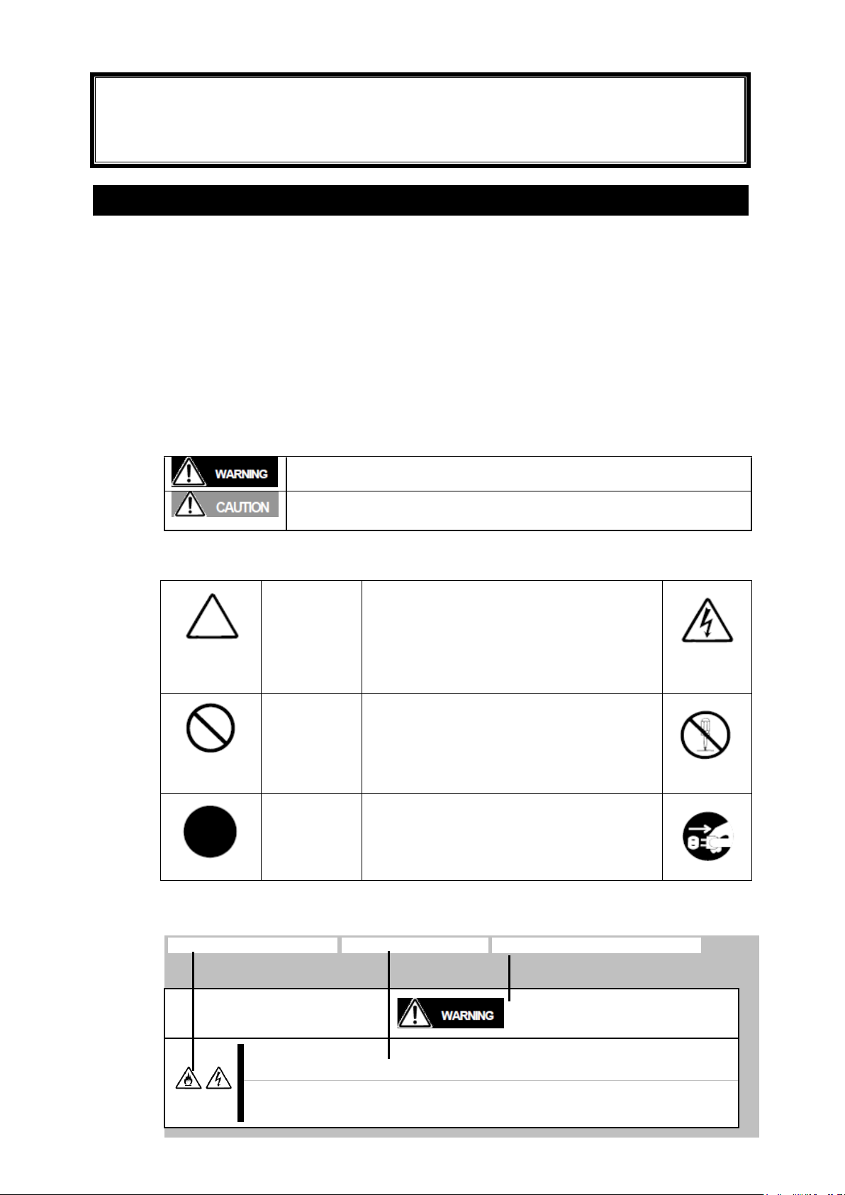
SAFETY INDICATIONS
To use this product safely, follow the instructions in this User’s Guide.
This guide explains components that pose a danger, types of dangers caused by failing to
follow the instructions, and actions taken to prevent them; such components are labeled
warning.
This guide and warning labels use “WARNING” and “CAUTION” to indicate a danger
depending on the degree. These terms are defined as follows:
This guide uses the following three types of symbols to give indications and precautions
against a danger. They are defined as follows:
Example of indications in this guide
Symbol indicating attention Description of a danger Term indicating degree of danger
3
Page 4
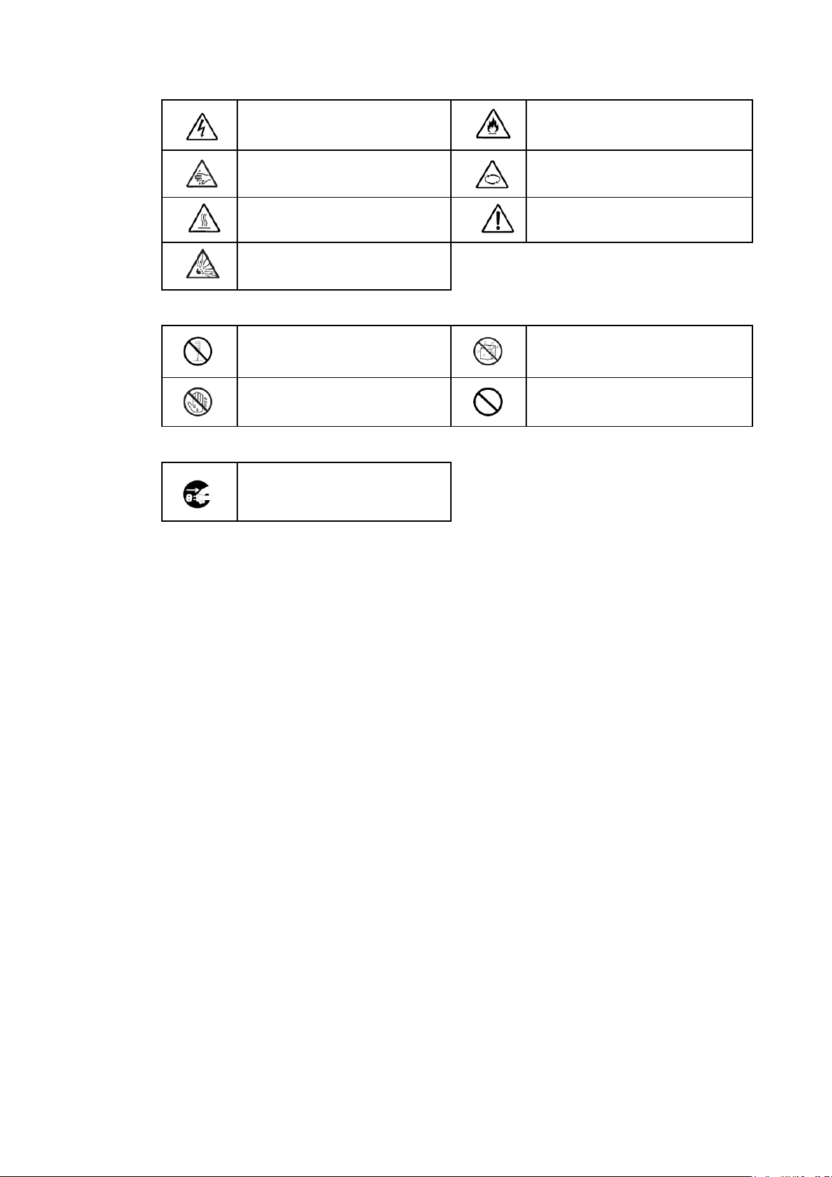
Descriptions of Symbols and Warning Labels
Indicates a risk of an electric shock.
Indicates a risk of a fire or smoke.
Indicates a risk of catching your
fingers
Indicates a risk of injury due to a
rotating object.
Indicates a risk of an injury due to
heat.
Indicates a general precaution or
warning that is not defined herein.
Indicates a risk of an explosion.
Do not disassemble, repair, or
modify the equipment.
Avoid using water or liquid nearby. If it
spills on the device, there is a risk of
an electric shock or fire.
Do not touch with wet hands. There
is a risk of an electric shock.
Indicates a general prohibition that is
not defined herein.
Indicates the instruction to unplug
the device and shut off the circuit
breaker of the power distribution
board.
Attention
Prohibited actions
Mandatory actions
4
Page 5
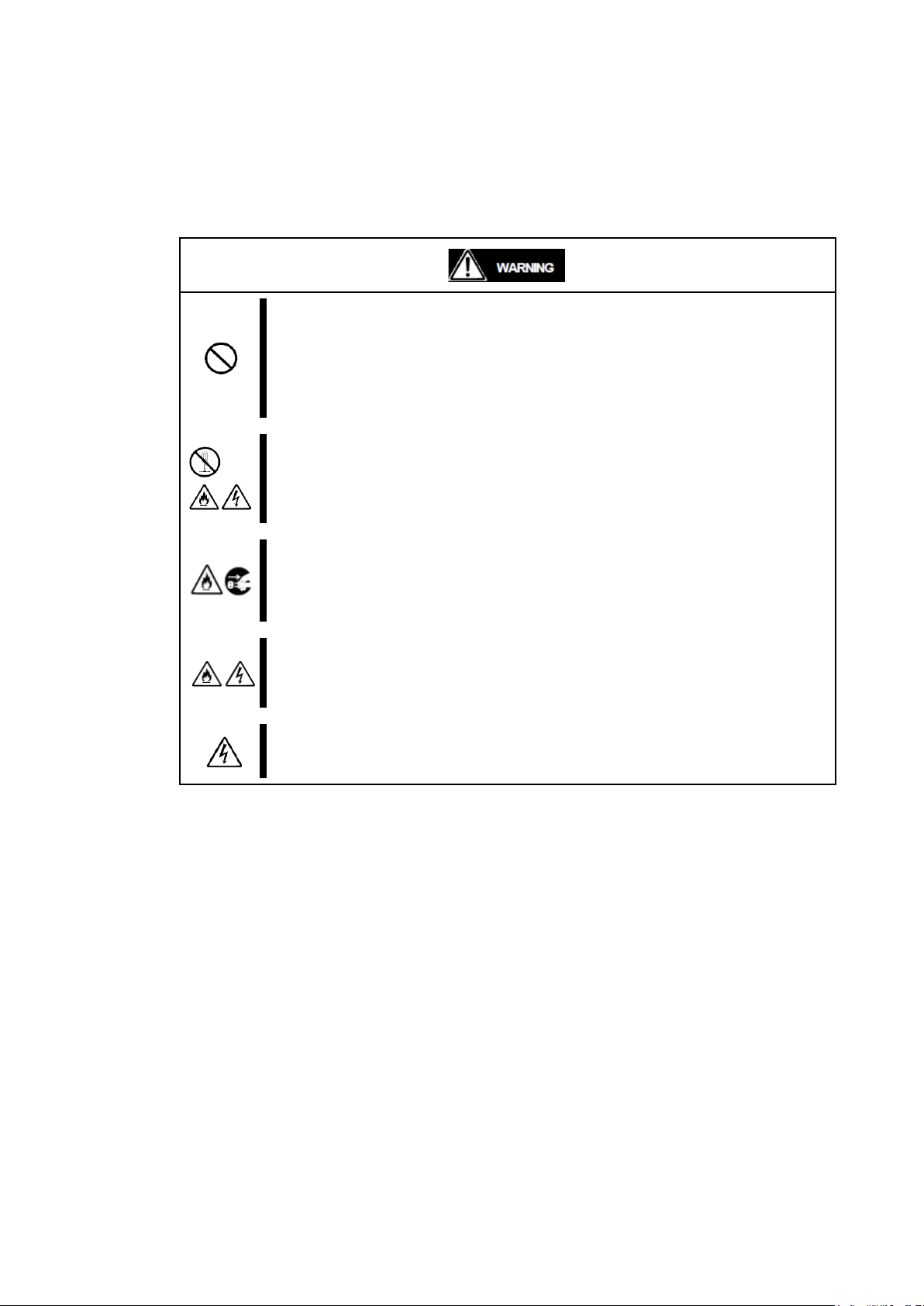
General precautions
Do not use the device in an operation where human lives are involved or high
reliability is required.
This device is not intended for using in controlling or using with facilities or systems where
human lives are involved or high reliability is required, including medical devices or
nuclear, aerospace, transportation, and traffic control facilities. NEC assumes no liability
for any accidents or damage to physical assets resulting from the use of this equipment in
such systems or facilities.
Do not disassemble, repair, or alter the device.
Unless described herein, never attempt to disassemble, repair, or alter the device.
There is a risk of an electric shock or fire as well as malfunction.
Do not continue to use the device if any smoke, odor, or noises are detected.
If the device emits smoke, odor, or noise, immediately turn off the POWER switch, unplug
the cords, and contact your sales representative. There is a risk of a fire.
Do not insert a wire or metal object.
Do not insert a wire or metal objects into a vent or disk drive slot. There is a risk of an
electric shock.
Do not install or remove multiple SWM/Pass-through cards simultaneously.
Install or remove SWM/Pass-through cards simultaneously.
Precautions for safety
Observe the precautions for safety described in this section. The Blade Enclosure
(SIGMABLADE-Hv2) on which this device is installed has power units. Carefully use them
to avoid any electric shock.
.
5
Page 6

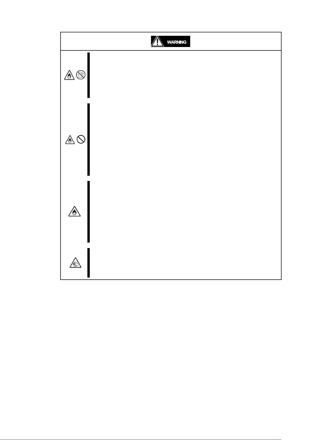
Prevent water or foreign objects from the product.
Do not let liquid (such as water) or any foreign objects (such as pins or paper clips) into
the product. There is a risk of fire, electric shock, and breakdown. When such things
accidentally enter the server, immediately turn off the power and unplug the cords. Do not
disassemble it yourself. Contact your sales representative.
Connect firmly.
Connect interface cables, option boards and modules as CPU blade securely. Install the
card securely on the Blade Enclosure. Failure to connect or install securely may result in
poor contact that can cause a fire or smoke.
6
Page 7
Installation, relocation and storage of the blade enclosure
Do not install the Blade Enclosure in a place other than specified.
Do not install the blade Enclosure in a place other than specified in this guide. Avoid
following locations. There is a risk of fire.
a dusty place
a humid place located near a boiler, etc.
a place exposed to direct sunlight
an unstable place
Do not use or store the Blade Enclosure in a corrosive environment.
Avoid using or storing the Blade Enclosure in an environment with possible exposure to
corrosive gas, such as those including but not limited to: sulfur dioxide, hydrogen sulfide,
nitrogen dioxide, chlorine, ammonia and/or ozone. Avoid installing the Blade Enclosure in
a dusty environment or that may be exposed to corrosive materials such as sodium
chloride and/or sulfur.
Avoid installing the Blade Enclosure in an environment that may have excessive metal
flakes or conductive particles in the air.
Such environments may cause corroding or short circuits within the Blade Enclosure,
resulting in not only damage to the Blade Enclosure, but may also lead to a fire hazard.
If there are any concerns regarding the environment at the planned site of installation or
storage, please contact your sales representative.
Do not use any unauthorized interface cable.
Use only the interface cables provided by NEC and locate a proper device and connector
before connecting a cable. Using an unauthorized cable or connecting a cable on an
improper destination may cause a short circuit, resulting in a fire.
Also, observer the following notes on using and connecting an interface cable.
Do not use any damaged cable connector.
Do not use any damaged cable.
Do not step on the cable.
Do not place any object on the cable.
Do not use the server with loose cable connections.
Be careful not to hurt your fingers.
Precaution required to avoid pinching your fingers when installing or removing the blade
server into or from a rack cabinet.
7
Page 8
Do not disassemble, repair or alter the server.
Never attempt to disassemble, repair or alter the server on any occasion other than
described in this manual. Failure to follow this instruction may cause an electric shock or
fire as well as malfunctions of the server.
Make sure to complete device installation.
Always connect power cords and interface cables firmly. An incompletely installed device
may cause a power failure, resulting in smoking or fire.
Unplug power cords before maintenance.
Before maintenance, power off all devices installed on the Blade Enclosure and unplug
power cords. Even if devices are powered off, there is a risk of electric shock or fire as well
as malfunction when maintenance is performed for the devices on the Blade Enclosure
with their power cords plugged.
Disconnect the power plugs from the power outlet occasionally and clean the plugs with a
dry cloth. Heat will generate if condensation is formed on a dusty plug, and may lead to a
fire.
Cleaning
8
Page 9

TIPS:
This warranty is available only for use in Japan.
Do not use it in any other country than Japan.
Preface
Thank you for purchasing our EM card. Installing the EM cards slot on N8405-040F: the Blade
Enclosure (SIGMABLADE-Hv2) provides the following management features. See [Basic Features] [Management Features] described later.
Power management
Cooling fan management
Chassis management in rack: manages the names of rack, the Blade Enclosure, and information of
modules in the Blade Enclosure
System monitoring: monitors statuses of power supply unit, fan and modules in the Blade
Enclosure.
External interfaces
Blade Enclosure interface connection
In the Package
The carton contains various accessories as listed below. Ensure that you have everything.
If you find any component missing, contact your service representative.
EM card × 1
CD-ROM containing document × 1
Notes on Use × 1
Warranty × 1
9
Page 10

About this User’s Guide
Text conventions
IMPORTANT:
Items that are mandatory or require attention when using the server
CHECK:
Points that are mandatory for verification when operating this product
or a software
TIPS:
Helpful and convenient piece(s) of information
For proper operation
The following conventions are used throughout this manual. For safety symbols, see “Safety
Indications” provided earlier.
Observe the following notes for successful operation of the product. Use of the product ignoring the
notes will cause malfunctions or failure of the server.
Clean the product on a regular basis. Regular cleaning proactively prevents various failures of the
server.
Do not use a cellular phone or pager around the Blade Enclosure.
Turn off the cellular phone or pager. Radio interference may cause malfunctions of the Blade
Enclosure.
Failure action
When the device fails, shut off the branch circuit breaker of the power distribution board and
unplug the device. Make sure to contact your maintenance personnel.
10
Page 11

Transfer to third party
Disposal
If this device or any of its accessories is either transferred or sold to a third party, observe the following
instructions.
Main unit of the Blade Enclosure
When this equipment is transferred or sold to a third party, hand over this User‟s Guide with the
device.
Software shipped with the Blade Enclosure
When the software shipped with this equipment is transferred or sold to a third party, the following
conditions should be satisfied.
Transfer all items shipped with this equipment.
The transferring party should keep no copy of any kind.
Satisfy conditions related to transfer and relocations as described in “Conditions to Use
Software” attached to the software.
Transfer the Blade Enclosure after uninstalling software if transfer of the software is not
permitted.
Contact NEC sales representative before disposal, collection or recycle of the device.
The EM card installed on the blade enclosure uses the lithium battery. (The battery is not replaceable.)
Contact NEC sales representative before disposing the EM card.
11
Page 12

Table of Contents
Notes for safety handling ................................................................................................. 3
SAFETY INDICATIONS ............................................................................................................. 3
Descriptions of Symbols and Warning Labels ................................................................... 4
Precautions for safety ............................................................................................................. 5
General precautions ......................................................................................................... 5
Installation, relocation and storage of the blade enclosure ......................................... 7
Cleaning ............................................................................................................................ 8
Preface ................................................................................................................................. 9
In the Package.................................................................................................................... 9
About this User’s Guide ................................................................................................. 10
Text conventions .................................................................................................................... 10
For proper operation.............................................................................................................. 10
Transfer to third party ........................................................................................................... 11
Disposal .................................................................................................................................... 11
Chapter 1 Names and Functions of Components ...................................................... 20
EM card .................................................................................................................................... 20
LED indication ......................................................................................................................... 21
STATUS LED ................................................................................................................. 21
ACTIVE LED .................................................................................................................. 22
ID LED ............................................................................................................................ 22
LINK/ACT LED ............................................................................................................... 22
SPEED LED ................................................................................................................... 22
Basic Features ........................................................................................................................ 23
Management Features ................................................................................................. 23
Power Management .................................................................................................................. 23
Cooling Management ................................................................................................................ 25
Interface Management between CPU Blade and Switch Module ........................................ 25
Chassis Information Management ........................................................................................... 25
Blade Enclosure Inter Connect ............................................................................................... 26
Bridge Function............................................................................................................ 27
SNMP Agent.................................................................................................................. 27
DUPLEX EM .................................................................................................................. 27
Chapter 2 Installation/Removal of EM Card ................................................................. 28
Safety Notes ............................................................................................................................ 29
Installation/Removal Preparation .......................................................................................... 30
Installation/Removal Procedure ............................................................................................ 30
Installation ..................................................................................................................... 31
Removing an EM Card ............................................................................................... 31
Connectors on the Rear Panel of the Blade Enclosure................................................. 32
Chapter 3 Using Command Line Console Feature ..................................................... 34
12
Page 13

Chapter 3 Using Command Line Console Feature ..................................................... 34
Connection ............................................................................................................................... 34
Connecting with Management Port ..................................................................................... 34
Connection via Serial Port ................................................................................................... 34
Connection via Network Port ............................................................................................... 35
Initial Settings ......................................................................................................................... 36
Date and time settings (EM card) ............................................................................ 36
User settings (EM card) ............................................................................................. 37
Rack settings (EM card) ............................................................................................. 38
Blade Enclosure settings (EM card) ........................................................................ 39
Network settings (EM card) ....................................................................................... 40
SNMP settings (EM card) ........................................................................................... 43
Setting module access right for an user (EM card) ............................................ 46
Power unit settings (EM card) .................................................................................. 47
Verifying, backing up and restoring the EM card configuration ....................... 48
DianaScope settings (EM card)................................................................................. 51
Other settings (CPU blade) ........................................................................................ 51
Console connection to switch module/pass-through card .................................. 52
Other settings (switch module/through card) ........................................................ 52
Checking operational status ................................................................................................. 53
Blade Enclosures ......................................................................................................... 53
Fan unit ......................................................................................................................... 53
Power unit ..................................................................................................................... 54
Updating the EM firmware ......................................................................................... 55
Setting EM firmware image ....................................................................................... 56
How to enter a command .......................................................................................... 64
Basics ....................................................................................................................................... 64
How to enter a command ..................................................................................................... 64
User account management ........................................................................................ 67
Overview ................................................................................................................................... 67
Default user ............................................................................................................................. 67
User account ........................................................................................................................... 67
Access right ............................................................................................................................ 67
Administrator ........................................................................................................................... 68
CLI additional user ................................................................................................................. 68
List of Commands .................................................................................................................. 69
Commands .................................................................................................................... 69
Command Specification ......................................................................................................... 79
General commands ...................................................................................................... 80
Clearing the CLI terminal screen ........................................................................................ 80
Terminating CLI ....................................................................................................................... 80
Displaying a help message .................................................................................................. 81
Displaying command entry history ..................................................................................... 82
13
Page 14

Rack management commands .................................................................................. 83
Naming a rack ......................................................................................................................... 83
Displaying a rack name ........................................................................................................ 83
Insert one or more blank between “SET”, “RACK” and “NAME”.Configuring the unique I
D for the rack ......................................................................................................................... 83
Configuring the unique ID for the rack ............................................................................. 84
Displaying the rack unique ISD ................................................................................ 84
Displaying connection status of Blade Enclosures in the same rack ............. 85
Enabling connection status of Blade Enclosures in the same rack ................ 85
Disabling connection status of Blade Enclosures in the same rack ............... 86
User management commands ................................................................................... 87
Adding a user .............................................................................................................. 87
Assigning a user (for CPU/blades/switch modules) ............................................. 88
Assigning a user (for EM card)................................................................................ 89
Disabling a registered user ....................................................................................... 89
Enabling a disabled user ........................................................................................... 90
Deleting users .............................................................................................................. 90
Configuring a password ............................................................................................. 91
Registering a user contact information .................................................................. 92
Registering a full user name .................................................................................... 93
Configuring a password ............................................................................................. 94
Configuring the access right ..................................................................................... 95
Displaying the registered users ................................................................................ 96
Cancelling user assignment (for CPU blade/switch module) .............................. 97
Cancelling user assignment (for EM card) ............................................................. 98
System management commands .............................................................................. 99
Forcefully disconnecting access to the EM serial console of switch module .......... 99
PING ........................................................................................................................................ 100
Initializing the configuration data (restoring default values) ....................................... 101
Configuring a domain name ............................................................................................... 113
Configuring the default gateway ....................................................................................... 113
Configuring NTP refresh intervals ..................................................................................... 114
Configuring the IP address of the primary NTP server ............................................... 114
Configuring the IP address of the secondary NTP server .......................................... 115
Configuring the name of a SNMP community allowing the Get operation .............. 115
Configuring the name of a SNMP community allowing the Get/Set operation ....... 116
Configuring the name of a SNMP community allowing the Trap operation ............ 117
Configuring an SNMP contact ........................................................................................... 118
Configuring an SNMP location .......................................................................................... 118
Configuring the Blade Enclosure location in the rack ................................................. 118
Configuring the rack height ............................................................................................... 119
Configuring the SNMP TrapAck port number ................................................................. 120
Displaying the network settings ........................................................................................ 120
14
Page 15

Displaying the SNMP settings ........................................................................................... 122
SNMP Trap test ..................................................................................................................... 123
Downloading the configuration settings (restoration) ................................................... 124
Switching active EM............................................................................................................. 125
Restarting the EM firmware ................................................................................................ 126
Configuring the function to automatically terminate CLI ............................................. 126
Configuring date and time .................................................................................................. 127
Configuring the function display events ......................................................................... 127
Configuring the asset tag of the Blade Enclosure ....................................................... 129
Configuring the machine serial number of the Blade Enclosure ............................... 129
Configuring the power control policy .............................................................................. 131
Configuring a time zone ..................................................................................................... 132
Displaying the configuration information in the CLI command format ..................... 133
Displaying date and time .................................................................................................... 136
Displaying the configuration of the function to display events ................................. 136
Displaying the fan information .......................................................................................... 136
Displaying the Blade Enclosure information ................................................................... 138
Displays the Blade Enclosure temperature ..................................................................... 142
Displaying the settings on the power management function ..................................... 143
Displaying the EM card/EM firmware version ................................................................. 144
Updating EM firmware ......................................................................................................... 145
Uploading (backing up) the configuration information ................................................. 146
Configuring the power saving mode ................................................................................ 147
Configuring the maximum consumable power setting ................................................. 148
Displaying the Fan unit rotation speed ........................................................................... 149
Displaying the Fan unit voltage/electric current ............................................................ 149
Power off CPU blades ......................................................................................................... 150
Power on CPU blades ......................................................................................................... 151
Resetting CPU blades .......................................................................................................... 152
Controlling the CPU blade ID LED ................................................................................... 152
Display the CPU blade information .................................................................................. 152
Listing the CPU blade information in a list ................................................................... 155
Displaying the CPU blade port map information (E-Keying information) ................. 156
Displaying CPU blade status ............................................................................................. 156
Configuring the power-on delay time of the CPU blade.............................................. 157
Displaying the power-on delay of the CPU blade ......................................................... 158
Displaying general information of the CPU blade (virtual LCD) ................................. 159
Connecting to the EM serial console of the switch module ...................................... 160
Powering off switch modules ............................................................................................ 162
Powering on switch modules ............................................................................................. 162
Restarting a switch module ............................................................................................... 163
Configuring a User Assigned Name of a switch module ............................................ 163
Controlling the ID LED of a switch module ................................................................... 164
15
Page 16

Displaying information on switch modules ..................................................................... 165
Displaying the list of switch modules ............................................................................. 166
Displaying the switch module map information (E-Keying information) ................... 167
Displaying the status of switch modules ........................................................................ 168
EM management commands .............................................................................................. 169
Controlling the EM card LED ............................................................................................. 170
Displaying information about the EM card(s) ................................................................. 171
Displaying EM card status ................................................................................................. 172
Configuring the language type for EM cards ................................................................. 173
Configuring an NEC DianaScope user password .......................................................... 174
Displaying an NEC DianaScope user password ............................................................ 174
Configuring the DSG status ............................................................................................... 175
Displaying the DSG status ................................................................................................. 175
Initializing OSD settings ...................................................................................................... 176
Disabling SIGMABLADEMONITOR password ................................................................... 176
Enabling SIGMABLADEMONITOR password .................................................................... 177
Resetting SIGMABLADEMONITOR ..................................................................................... 177
Setting SIGMABLADEMONITOR backlight off time ........................................................ 178
Setting SIGMABLADEMONITOR password ....................................................................... 178
Displaying SIGMABLADEMONITOR backlight off time .................................................. 179
Displaying SIGMABLADEMONITOR password setting ................................................... 179
Displaying SIGMABLADEMONITOR firmware revision ................................................... 180
Updating SIGMABLADEMONITOR firmware ..................................................................... 180
Log collection command ..................................................................................................... 181
Configuration management ................................................................................................. 182
Appendix ................................................................................................................................ 183
Chapter 4 Using Web Console Feature ...................................................................... 184
Connection ............................................................................................................................. 184
Login and Basic Operation ................................................................................................ 184
Screen Layout ............................................................................................................ 186
Component names................................................................................................................ 186
Basic operations ........................................................................................................ 187
Selecting menu items .......................................................................................................... 187
Selecting tabs in menu items ............................................................................................ 187
Displaying System Status ................................................................................................... 190
System Status List .................................................................................................... 190
CPU Blades ................................................................................................................. 191
Switch modules .......................................................................................................... 192
Power unit ................................................................................................................... 195
Fan unit ....................................................................................................................... 196
Switch module ............................................................................................................ 199
Power units ................................................................................................................. 205
Fan units ..................................................................................................................... 206
16
Page 17

Rack information ........................................................................................................ 207
Enabling Blade Enclosure inter connect ......................................................................... 207
Displaying rack information ................................................................................................ 209
Power information ..................................................................................................... 210
Input power ............................................................................................................................ 211
Power managed .................................................................................................................... 212
Power supply ......................................................................................................................... 213
Blade ....................................................................................................................................... 214
Switch module ....................................................................................................................... 215
Fan unit .................................................................................................................................. 215
Displaying Product Information ......................................................................................... 216
Product information list ............................................................................................ 216
Saving the product information ......................................................................................... 217
Configuration ......................................................................................................................... 218
Editing configurations ............................................................................................... 218
Power management .............................................................................................................. 220
Rack ........................................................................................................................................ 222
Blade enclosure .................................................................................................................... 223
DianaScope ............................................................................................................................ 224
CPU blade: boot time delay ............................................................................................... 225
Blade priority ......................................................................................................................... 226
SNMP ...................................................................................................................................... 228
Others ..................................................................................................................................... 230
Apply ....................................................................................................................................... 231
Backup configuration ................................................................................................ 232
Run .......................................................................................................................................... 232
Restore configuration ................................................................................................ 233
Configuration backed file .................................................................................................... 233
Password configuration ............................................................................................ 234
Change Password for User ................................................................................................ 234
Change SIGMABLADE Monitor password ........................................................................ 235
Change Password for Linkage with DianaScope ........................................................... 236
Log management ....................................................................................................... 237
Collect EM Log ..................................................................................................................... 237
Update Firmware ........................................................................................................ 238
Update EM Card Firmware ................................................................................................. 238
Switchover .............................................................................................................................. 241
User management ................................................................................................................. 241
Chapter 5 SIGMABLADE Monitor ................................................................................. 242
Components of SIGAMABLADE monitor ......................................................................... 242
LED indication ....................................................................................................................... 242
Using SIGMABLADE Monitor .............................................................................................. 243
Top menu .................................................................................................................... 243
17
Page 18

Main Menu ................................................................................................................... 243
Switching KVM/DVD ............................................................................................................. 244
Displaying System Information ............................................................................... 245
Displaying Fan/Power Status ................................................................................... 245
Displaying EM Card Information ........................................................................................ 247
Displaying CPU blade information ......................................................................... 248
Displaying virtual LCD ......................................................................................................... 248
Displaying CPU blade status ............................................................................................. 248
Displaying Switch Module Information .................................................................. 249
Displaying Switch Module Status ...................................................................................... 249
System Setup ............................................................................................................. 250
Setting for EM ....................................................................................................................... 250
Backup of EM Configuration File ...................................................................................... 253
Restoring EM configuration file ......................................................................................... 254
Updating EM Firmware ........................................................................................................ 256
Backup of EM Firmware ..................................................................................................... 260
EM Switchover ...................................................................................................................... 262
Collecting logs ........................................................................................................... 263
EM Log ................................................................................................................................... 263
Diagnosis menu .................................................................................................................... 265
Setting OSD (On Screen Display) .......................................................................... 266
Setting OSD Hot Key ........................................................................................................... 267
Setting Keyboard Type ........................................................................................................ 268
Maintenance Menu ................................................................................................................ 269
Saving OSD Setup Data ...................................................................................................... 269
Diagnosis by SIGMABLADE Monitor ................................................................................ 270
Diagnostic Process .................................................................................................... 270
Indication of diagnosis end ..................................................................................... 271
Indication of EM Card Error .................................................................................... 272
Switchover between KVM and DVD .................................................................................. 272
Chapter 6 Using OSD (On Screen Display) Feature ................................................ 273
Activating OSD Menu Mode .................................................................................... 274
Operation in OSD Menu Mode ................................................................................ 275
Blade Selection Menu (Main Menu) .................................................................................. 275
Blade Control Menu ............................................................................................................. 280
Rack control menu ............................................................................................................... 284
Enclosure control menu ...................................................................................................... 286
On Screen Display (OSD) Setup Menu ............................................................................ 288
Operation in OSD Simple Mode ........................................................................................ 293
Activating OSD Simple Mode .................................................................................. 293
Operation in OSD Simple Mode ............................................................................. 294
KVM Switchover .................................................................................................................... 294
Changing Server Name Resident Mode ........................................................................... 294
18
Page 19

Server Name Resident Mode .............................................................................................. 295
Activating Server Name Resident Mode ............................................................... 295
Chapter 7 Server Management Software .................................................................... 296
NEC ESMPRO Manager/Agent ............................................................................................ 296
NEC DianaScope Manager/Agent ....................................................................................... 297
Chapter 8 Troubleshooting ........................................................................................... 298
LED indication ....................................................................................................................... 298
Error message on SIGMABLADE Monitor ....................................................................... 298
Error message on SIGMABLADE Monitor ....................................................................... 299
Overview ...................................................................................................................... 299
Collection using Web Console................................................................................ 299
Collection using SIGMABLADE Monitor ................................................................ 299
Collection using Command Line Console ............................................................ 300
Collection using NEC ESMPRO Manager ............................................................. 300
Others ..................................................................................................................................... 301
19
Page 20
Chapter 1
EM card
6 7 10 2 3 4 5 8 9
1
Names and Functions of Components
1. RESET switch
This resets the EM card.
2. STATUS LED (green/amber)
This indicates the status of EM card. See “LED indication” for details.
3. ACTIVE LED (green)
This light when the EM card is specified as active EM.
4. ID LED (blue)
Identifies the device. See “LED indication” for details.
5. ID switch
Turns on or off the ID LED. Pressing this switch notifies the management PC that the
target
EM card is identified.
6. Serial port
This is used as a management port.
7. Management LAN interface
This is used as a management LAN port.
8. LINK/ACT LED (green)
This indicates LAN access status. See “LED indication” for details.
9. SPEED LED (amber)
This indicates transfer rate of LAN port. See “LED indication” for details.
10. Lithium battery
20
Page 21

LED indication
The following are the names of device components.
STATUS LED
The table below shows the condition of STATUS LED and recommended action
21
Page 22

TIPS:
For the names and LED indications of SIGMABLADE monitor, see Chapter 5.
ACTIVE LED
This LED lights green when the EM card is specified as “Active” card. If the EM card is specified as
“Standby” card, this LED does not light.
ID LED
The ID LED of the EM card which is selected by ID switch or software command goes on blue.
LINK/ACT LED
This LED lights green when LAN port is connected with network. It flashes green while processing
data transmission.
SPEED LED
The LAN port supports 100BASE-TX and 10BASE-T interface. This LED turns on amber while the
network port is linking with 100Mbps, and turns off while linking 10Mbps.
22
Page 23

Basic Features
TIPS:
For the third and the subsequent power units, DC output is turned on /off as needed.
This section describes the basic feature of the EM card.
Management Features
The below describes the management features of the EM card.
Power Management
The EM card manages DC output of power unit(s) in the Blade Enclosure. When the AC power is
supplied to the Blade Enclosure, the EM card starts operating. If two or more power units are installed
in the Blade Enclosure and they are working normally, the EM card turns on the DC output of two
power units among them.
The EM card manages the power consumption in the entire system.
The maximum power consumption available in the entire system varies depending on the power
capacity supplied to the system and the configuration of power units (including types and number of
units).
The maximum power consumption management is to manage the power consumption of each of the
modules configuring the system so that the maximum power consumption in the system is maintained
within a certain value (called as “ceiling control”).
One of the following three upper limit values is used for ceiling control.
A. Upper limit determined by the types, number of power supply units, and input voltage.
B. If the UPS is managed by EM card, the EM card calculates the upper limit based on the type of
UPS connected.
C. Upper limit specified for input voltage regardless of the configuration of power units or use of
UPS manager. See “Configuration File” in Chapter 3 and “Configuration” in Chapter 4 for details.
The EM card uses the value smallest among A, B and C as the upper limit value, and performs ceiling
control system power consumption.
You can select a power redundancy mode (N+N redundant or N+1 redundant mode) and a power
control policy (CPU performance, “maintain redundancy” or “recover redundancy” mode) as methods
of power management by the EM card.
23
Page 24

There are two power redundancy modes, or N+N redundant and N+1 redundant mode.
TIPS:
A CPU blade subject to power-on issues the permission of using power to the EM card. The
power is not turned on if the EM card does not permit the CPU blade to use the power due to an
event such as power shortage.
In the N+N redundant mode, each power unit is divided into two groups to configure the
redundant power supply system. If a power supply in a group is defected, only the power of
the other group can maintain the system operation.
In the N+1 redundant mode, power units are not groped but each power unit is controlled
individually. Using a power supply in addition to the number of power units required for the
normal system operation enables redundant power system.
The power control policy includes three modes, or CPU performance, “maintain redundancy” and
“recover redundancy” modes.
The CPU performance mode makes the EM card prioritize the operation performance of CPU
blades. In this mode, if the EM card cannot accept a new power request from a CPU blade
with the power redundancy maintained, the EM card releases the power redundant
configuration and permits the new power request from the CPU blade. (If a power unit is
defected during operation under the release of the power redundant configuration, then the
system may be forcibly shut down.)
The “maintain redundancy” mode makes the EM card accept a new power request from a
CPU blade within the range allowing the power redundancy to be maintained. If the EM card
cannot accept a new power request from a CPU blade with the power redundancy maintained,
the EM card denies the request. In the “maintain redundancy” mode, any measures is not
taken if the power redundancy is lost due to an event such as a failure of a power unit. (When
a power unit is defected further in no power redundancy status, the system may be shut down
forcibly.)
The “recover redundancy” mode makes the EM card accept a new power request from a CPU
blade within the range allowing the power redundancy to be maintained and limit the
operation performance of CPU blades to suppress the power consumption for recovery of the
power redundancy if the redundancy is lost due to an event such as a failure of a power unit.
(Depending on operations of CPU blades, the EM card cannot reduce the power consumption
to the value allowing the power redundancy to be recovered.) When a switch module inserted
to a switch module slot issues a power-on request, the EM card checks the power consumption
of the switch module and turns on the power of the switch module if the power-on is possible
within the maximum power consumption management described above.
When a switch module, which is inserted to a switch module slot, issues a power-on request, the
EM card checks the power consumption often switch module and turns on the power of the switch
module if the power-on is possible within the maximum power consumption management
described above.
When a CPU blade inserted to a CPU blade slot requests the permission of using power, the EM
card permits the CPU blade to use the power if the power consumption is possible within the
maximum power consumption management described above.
24
Page 25

Cooling Management
TIPS:
Depending on the installed number of fan units and CPU blades and their installed locations, when the
EM card judges that the cooling capacity is insufficient, it may not permit the power-on of CPU
blade.
In such a case, check the fan units and CPU blades so that they are appropriately installed.
TIPS:
For connection between the CPU blade and switch module in the Blade Enclosure, refer to the User‟s
Guide of the switch module.
While the CPU blade is powered on, the amount of necessary cooling air changes according to the
temperature condition. The EM card determines the rotation speed of the fan according to the installed
number of fan units and others, and controls the fan so that it rotates in optimum speed.
Interface Management between CPU Blade and Switch Module
If the CPU blade is incorrectly connected with the switch module, it will be damaged. EM card checks
the interface between them to prevent this damage. If the interface is improper, the EM card suppressed
power-on of the relevant CPU blade and the switch module, or disable the connection port.
Chassis Information Management
The EM card manages the names of the rack, a Blade Enclosure, CPU blades, and switch modules.
Except for CPU blade name, they are specified in a configuration file.
25
Page 26

IMPORTANT:
For the Blade Enclosure inter connect, use LAN cables (straight) as short as possible. LAN
cables of three meter or less are recommended.
Do not connect a LAN cable to the UPPER port of the Blade enclosure at the top in a rack and
the LOWER port of the Blade Enclosure at the bottom.
CHECK:
Check that LAN cables are connected above and below appropriately. Each of the EM cards
recognizes the positional relationship among the Blade Enclosures in the rack depending on the cable
connections to the UPPER and LOWER ports on the Blade Enclosures. Some incorrect cable
connection disables the EM cards to recognize the positional relationship among the Blade Enclosures
properly.
TIPS:
Up to six Blade Enclosures can be subject to the Blade Enclosure inter connect.
Blade Enclosure Inter Connect
If more than one Blade Enclosure (SIGMABLADE-Hv2) are mounted in a single rack, connecting the
UPPER port, a connector on the rear face of a Blade Enclosure, to the LOWER port, a connector on the
rear face of the Blade Enclosure just above, and the LOWER port, another connector on the rear face,
to the UPPWER port, a connector on the rear face of the Blade Enclosure just below, through LAN
cables (straight) allows the EM cards to share the rack name and its unique ID among the connected
blade enclosures.
The EM cards can read the status information of the Blade Enclosures and display the information on
Web consoles.
The Rack Information screen on a Web console has the link of each connected Blade Enclosure to the
Web console.
When the same user name and password are set for all the Web consoles, you can automatically log in
to any Web console through the link to the Web console.
See Chapter 4 for details of the Web console.
26
Page 27

Bridge Function
TIPS:
When bridging, the EM card executes port filtering to prevent unnecessary packet from flowing in the
network.
The port number 49623 is used exclusively by EM card, and cannot be used in any other purposes.
IMPORTANT:
In the duplex configuration, the revision of the EM firmware for EM card should be the same as
that in another EM card.
TIPS:
When switchover command is executed, the bridge feature is temporarily stopped, and the
management LAN interface may temporarily be disconnected.
The EM card bridges a packet from the EM1/EM2 port at the rear of the Blade Enclosure to the
internal network. It enables network communication between the management unit of the CPU blades
and switch modules in Blade Enclosure (e.g., EXPRESSSCOPE Engine) and the external devices.
SNMP Agent
SNMP is a protocol used to communicate the management data among network devices.
The administrator of the EM card can use SNMP to monitor the operating status of the EM card and
the blade system (Blade Enclosure, fan units, or power units) which the EM card manages.
Registering community name and SNMP trap message destination are to be specified in configuration
file.
DUPLEX EM
Installing two EM cards in the slots EM1 and EM2 enables duplex configuration. In the duplex
configuration, either of two EM cards works as an active EM to perform various features of the EM
card, and another one works as standby EM card. Two cards are connected with the internal serial
interface to transmit/receive information synchronously.
When an active EM fails or when the switchover command is executed, an active EM is changed to
standby EM after the system is rebooted. The standby EM is then works as an active EM.
27
Page 28

Chapter 2
IMPORTANT:
The EM card may be installed or removed by any user. NEC assumes, however, no liability for
damage to devices or the server or malfunction of the server resulted from installation by the
user. NEC recommends you ask your service representative for installing or removing the EM
card.
Make sure to use only cables authorized by NEC. Repair of the server due to malfunctions,
failures, or damage resulted from using an unauthorized cables will be charged.
Installation/Removal of EM Card
Two EM cards can be installed in the slots located at the front of the Blade Enclosure.
This section describes how to install the EM card in Blade Enclosure, and notes on using the EM card.
28
Page 29
Safety Notes
Observe the following instructions to use the server safely. Failure to follow these
instructions may result in death or serious personal injury. See pages 3 to 8 for
details.
Do not disassemble, repair, or alter the server.
Unplug the power cord before working with the server.
Observe the following instructions to use the server safely. Failure to follow these
instructions may cause a fire, personal injury, or property damage. See pages 3
to 8 for details.
Make sure to complete installation.
Do not pinch your finger(s) with component.
Observe the following notes to install or remove the EM card safely and properly.
Keep any component in an anti-static bag until you actually install it to Blade Enclosure.
Hold a component by its edge to avoid touching any terminals or parts.
To store or carry any component, place it in an anti-static bag.
29
Page 30
Installation/Removal Preparation
TIPS:
We recommend you to make backup copy of configuration data of EM card before starting
work.
For backup/restore procedure, see “Backup/Restore of Configuration File” described later.
Installation/Removal Procedure
Observe the following instructions to use the server safely. Failure to follow these
instructions may cause a fire, personal injury, or property damage. See pages 3
to 8 for details.
Make sure to complete installation.
Do not pinch your finger(s) with component.
Prepare a Phillips screwdriver before starting installation or removal.
If the EM cards are not in redundant configuration, the configuration data before replacement will be
lost. You must reconfigure the EM card after replacement.
Install or remove the EM card in the following procedure.
30
Page 31

Installation
TIPS:
To remove an EM card, push the ejector on the handle.
TIPS:
We recommend backing up the configuration of the EM card..
For backup/restore procedure, see “Backup/Restore of Configuration File” described later.
IMPORTANT:
As long as
–no EM cards are installed, or
–an ACTIVE LED of EM card(s) is not lit after EM card is installed,
do not install or uninstall CPU blades, switch modules, fan units, power units and power cords.
Use the following procedure to install this product.
Locate an appropriate slot and insert an EM Card
by pushing its handle.
Removing an EM Card
Follow the reverse order of that for installation to remove an EM Card.
31
Page 32

Connectors on the Rear Panel of the Blade Enclosure
IMPORTANT:
The UPPER and LOWER ports on the Blade Enclosure are exclusively used for the Blade Enclosure
inter connect. Do not connect any other devices to the ports.
TIPS:
Link local address 169.254.0.0/16 is used for the Blade Enclosure inter connect.
1 2 3
4 5 6
Connectors on the rear panel of
the Blade Enclosure.
The below figure shows the connectors on the rear panel of the Blade Enclosure.
1. UPPER port
This is used when more than one Blade Enclosure are mounted in a rack and the Blade
Enclosure inter connect is used.
This is connected to the LOWER port on the Blade Enclosure just above through a
straight LAN cable. If the Blade Enclosure is located at the top of the rack, the UPPER
port is not used.
2. LOWER port
This is used when more than one Blade Enclosure are mounted in a rack and the Blade
Enclosure inter connect is used.
This is connected to the UPPER port on the Blade Enclosure just above through a
straight LAN cable. If the Blade Enclosure is located at the top of the rack, the LOWER
port is not used.
3. Serial port
This is not used in normal operation.
4. Monitor connector
This is to connect with the display unit. It is used by the SIGMABLADE monitor and OSD
function.
5. Keyboard connector
This is to connect with the PS/2 keyboard. It is used by the SIGMABLADE monitor and
OSD function.
6. Mouse connector
Connector to connect with the PS/s mouse. It is used by the SIGMABADE monitor and
OSD function.
32
Page 33

● Connection of UPPER port / LOWER port
This figure shows the example connection
when 4 blade enclosures in the same rack.
UPPER
LOWER
UPPER
LOWER
UPPER
LOWER
UPPER
LOWER
[Important]
The UPPER and LOWER port are for the connection between blade enclosures only.
DO NOT connect other components to these ports.
33
Page 34

Chapter 3
Using Command Line Console Feature
This section explains the command line console feature.
Connection
To use the command line console feature, a management console (e.g., personal computer) must be connected to
the management port.
Connecting with Management Port
The EM card has two interfaces; the serial port and the network port (100Base-Tx/10Base-T) as a management
port.
IMPORTANT: To connect with the management network, use "Management LAN
Interface" at the front of the EM card.
NOTE: Connect with the management port when providing initial setup or
maintenance of EM card.
Connection via Serial Port
Connect a management console (e.g., personal computer) to the serial port. When you use the EM card for the
first time, the management console must be connected.
The management console such as PC must have a communication software conformed to VT-100.
Set the communication software as follows:
– Baud rate: 115200bps
– Data length: 8 bits
– Parity: None
– Stop bit: 1
– Flow control: None
IMPORTANT: A leased line cannot be connected to the serial port directly.
34
Page 35

Connection via Network Port
TELNET or SSH (password authentication) is used for connection with network. To login the EM card with
TELNET/SSH, use the IP address you have assigned previously in the procedure for connection via the serial
port.
NOTE: The default IP address is 192.168.1.8/24. You may connect with the local
network that accepts this IP address to set an IP address. Note that, however,
connection with network is aborted when you change an IP address. The
SIGMABLADE monitor described in Section 5 also allows you to set an IP address.
IMPORTANT: To connect with the management network, use "Management LAN
Interface" connectors at the front of the EM card.
35
Page 36

Initial Settings
CHECK:
The default password for “Administrator” is “Admin”. For security change the default password
to new one.
Configure the initial settings by “Administrator” or a user whose access right is
“ADMINISTRATOR” or “OPERATER.” Some initial settings accept only Administrator or a
user whose access right is “Administrator.”
Configure the initial settings from the active EM card.
The default value of IP address of EM card is 192.168.1.8 ~ 11 (subnet mask: 255.255.255.0).
When connecting to an EM card from the EM console for the first time after your purchase for
initial settings, connect to 192.168.1.8 (If the settings have not been changed).
Changing date settings (Required when not using the NTP function)
Configure date and time of an EM card.
SET DATE <MMDDhhmm({CC}YY)> <time zone>
- MM: month DD: date hh: time mm: minute CCYY: year
- time zone: refer to “Time zone” in “Appendix. (180 page) ” The default value is
JST.
Configuring an NTP server
(For using the NTP function, you must configure the primary NTP server setting and
ENABLE NTP. Configuring the secondary NTP server is optional.)
Setup the NTP server to be referred by the EM card.
Before this, you must complete “Network settings (EM card)”.
(It takes about 5 seconds for the command to complete.)
SET NETWORK NTP PRIMARY <primary NTP server address>
(SET NETWORK NTP SECONDERY <secondary NTP server address>)
SET TIMEZONE <time zone>
Time zone: refer to “Time zone” in “Appendixes. (180 page) ” The default value is
JST.
ENABLE NTP
Configure initial settings of modules installed on the blade enclosure such as EM cards and CPU blades
by using the EM serial console or the EM console.
Date and time settings (EM card)
1. Confirm whether the EM card is powered on.
2. Ensure that you have logged in as “Administrator” or a user whose access right is
“ADMINISTRATOR” or “OPERATOR” from a CLI of the EM serial console or the EM console.
(If you have not, log in as “Administrator” or a user whose access right is “ADMINISTRATOR”
or “OPERATOR.”)
3. Ensure that the following information by running commands on the CLI. (For details, refer
to ”Commands.”)
4. Execute the command below on the CLI to check the settings you made have taken effect.
For details, refer to “.”
When the date and time settings have been modified, run the SHOW DATE command.
When the NTP server settings have been configured, run the SHOW NETWORK command.
This completes steps to configure date and time or NTP server settings.
36
Page 37

User settings (EM card)
Changing the password of Administrator (highly-recommended)
Change the password of Administrator.
The password can contain three to eight alphanumeric characters.
Do not forget the password of Administrator.
If you forget, password recovery is necessary. (For information on how to recover
password, refer to “Password recovery”.)
SET PASSWORD
New Password : ******** (Type a password)
Confirm : ******** (Type the same password)
Registering regular users (when adding a user, ADD USER is required. FULL NAME
is optional.)
Register regular user accounts as necessary.
ADD USER <user name (within 13 characters)>
New Password : ******** (Type a password)
Confirm : ******** (Type the same password)
SET USER FULLNAME <user name> <full name (within 32 characters)>
Configuring the access right of the regular users (optional)
Configure the access right of the regular users. (The default value of access right of regular
user is USER.)
SET USER ACCESS <user name> [ADMINISTRATOR | OPERATOR | USER]
TIPS:
When two EM cards are installed and you configure the password of the regular users or
Administrator
on the active EM card, the same values are automatically allocated to the standby EM card.
When you add users, or changed the access rights, run the SHOW USER <user name>
command.
1. Confirm whether the EM card is powered on.
2. Confirm that you have logged in as “Administrator” or a user whose access right is
“ADMINISTRATOR” or “OPERATOR” from a CLI of the EM serial console or the EM console.
(If you have not, log in as “Administrator” or a user whose access right is “ADMINISTRATOR”
or “OPERATOR.”)
3. Configure the following information by running commands on the CLI. (For details, refer to
“Commands.”)
4. Execute the command below on the CLI to check the settings you made have taken effect
(for details, refer to “Commands”).
This completes the steps to configure the user settings.
37
Page 38

Rack settings (EM card)
Rack name (required for report processing)
Configure the name of the rack on which the EM card is installed (within 32 characters).
(Specify any unique name to identify the rack.)
SET RACK NAME <rack name>
TIPS:
When interlude connection is enabled, the Rack Name is determined according to the Rack Name set
in the bottom blade enclosure unit. If you change the name when InterBlade connection is enabled,
the changed name will be reflected in all blade enclosures connected with this feature.
You can change a Rack Name from any one of the blade enclosures connected with InterBlade
connection.
1. Confirm whether the EM card is powered on.
2. Ensure that you have logged in as “Administrator” or a user whose access right is
“ADMINISTRATOR” or “OPERATOR” from a CLI of the EM serial console or the EM console.
(If you have not, log in as “Administrator” or a user whose access right is “ADMINISTRATOR”
or “OPERATOR.”)
3. Configure the following information about the rack by running commands on the CLI. (For details,
refer to “Commands.”)
4. Execute listed command in CLI mode. Confirm that the settings are applied. For detail, refer to
the command specification.
Execute "SHOW ENCLOSURE INFO" command when the name or asset number of enclosure is
defined.
This completes the steps to configure the user settings.
38
Page 39

Blade Enclosure settings (EM card)
Blade enclosure name (required for report processing)
Configure the name of the blade enclosure on which the EM card is installed (within 32
characters)
(Specify any unique name to identify the blade enclosure.)
SET ENCLOSURE NAME <the blade enclosure name>
Blade Enclosure asset number (optional)
Configure an asset number of the blade enclosure on which the EM card is installed
(within 32 characters).
Configure any asset number of the blade enclosure (such as a number allocated for
managing assets in your organization).
SET ENCLOSURE ASSET TAG <the asset number>
1. Confirm whether the EM card is powered on.
2. Ensure that you have logged in as “Administrator” or a user whose access right is
“ADMINISTRATOR” or “OPERATOR” from a CLI of the EM serial console or the EM console.
(If you have not, log in as “Administrator” or a user whose access right is “ADMINISTRATOR”
or “OPERATOR.”)
3. Configure the following information about the Blade Enclosure by running commands on the CLI.
(For details, refer to “Commands.”)
4. Execute the command below on the CLI to check the settings you made have taken effect.
For details, refer to “Commands.”
When the name or asset number of the blade enclosure has been configured, execute the
SHOW ENCLOSURE INFO command.
This completes the steps to configure the user settings.
39
Page 40

Network settings (EM card)
IMPORTANT:
Make sure in advance that IP addresses to be configured are able to use in your network. When
IP address or subnet mask settings become unknown after the configuration, reconfigure them
on the EM serial console.
Make sure in advance that IP addresses to be configured are able to use in your network.
When IP address or subnet mask settings become unknown after the configuration, reconfigure
them on the EM serial console.
IP addresses that you are setting should have a subnet address that is able to use in your network.
IP addresses of EM cards, CPU blades and switch modules must have a common subnet mask.
Make up IP addresses with the same subnet in advance.
Make sure that IP addresses you are setting do not overlap with the IP addresses of other
machines on your network.
Configure unique IP address for each module to be installed on the blade enclosure.
Even when you operate the blade enclosure with some modules powered off, all the modules
installed on the blade enclosure must have unique IP addresses. (Pay extra attention when you
configure IP addresses of modules without using the DHCP function. If you are using modules
for the first time, all of them may have the same IP address set to them. In such a case, you must
reconfigure IP addresses to give a unique IP address to each one of them.)
When a first IP address is configured, consecutive numbers are automatically allocated for the IP
addresses of EM cards, CPU blades/switch modules for management LAN. Ensure that none of
the IP addresses has the same address. Not only the first IP address but also
automatically-allocated IP addresses must be within an appropriate range.
Floating IP is an IP address that dynamically switches according to the status of EM card
(active/standby). Regardless of where the EM card is physically stored, if the EM card is active,
floating IP (active EM) is allocated, and if the EM card is stand-by, floating IP (stand-by EM) is
allocated. When the status of the EM card switches to active/stand-by an occurrence of a failure
on the EM card or the FORCE TAKEOVER command, floating IP is automatically switched
accordingly. By using floating IP, you can use active EM (or stand-by EM) while where the EM
card is physically stored remains transparent. (For detailed information on active EM card etc.,
refer to “EM card” on page 58.)
Static IP address (EM card slot 1/2) is an IP address that is determined depending on where the
EM card is physically stored. (the left is EM card slot 1, the right is EM card slot 2.)
Static IP address is not affected by whether the status of EM card is active or stand-by.
The following values can't be specified for EM cards, CPU blades and switch modules.
*.*.*.0, *.*.*.255 ("*": the wildcard character)
1. Confirm whether the EM card is powered on.
2. Ensure that you have logged in as “Administrator” or a user whose access right is
“ADMINISTRATOR” or “OPERATOR” from a CLI of the EM serial console or the EM console.
(If you have not, log in as “Administrator” or a user whose access right is “ADMINISTRATOR”
or “OPERATOR.”)
3. Determine the network configuration.
40
Page 41

Configuration example
(1)
EM card –network configuration
Floating IP 192.168.1.4
Four consecutive IP addresses
(Specify the IP address of
floating IP (active EM))
(active EM)
Floating IP 192.168.1.5
(stand-by EM)
Static IP address 192.168.1.6
(EM card slot 1)
Static IP address 192.168.1.7
(EM card slot 2)
(2)
CPU blade (Slot 1~16) -network configuration
Slot 1 192.168.1.8
24 consecutive IP addresses
(Specify the IP address of CPU
blade (slot 1))
Slot 2 192.168.1.9
Slot 3 192.168.1.10
Slot16 192.168.1.23
(3)
Switch module (Slot1~8) -network configuration
Slot 1 192.168.1.24
Slot 2 192.168.1.25
Slot 3 192.168.1.26
Slot 8 192.168.1.31
(4)
Configuration of subnet mask and gateway (this configuration is used across EM cards, CPU
blades and switch modules)
Subnet mask 255.255.255.0
Gateway 192.168.1.99
(5)
Configuration of DNS server (this configuration is used across EM cards, CPU blades and
switch modules)
Primary DNS 192.168.1.111
Secondary DNS 192.168.1.123
CHECK:
If you change the IP address of the EM card while you are using a CLI on the EM console, the EM
console is disconnected from the EM card. Change the target IP address of the terminal emulator of
the EM console to the new IP address of the EM card to log on again. Depending on a new IP address
of EM card, values of the network configurations of EM console and other network machines must be
set to the appropriate values in advance.)
Note that the following is an example. Configure each IP address and subnet mask according to your
usage environment.
4. Configure the following information by executing the commands on a CLI.
(For details, refer to “Commands.”).
― Each IP address setting (Required)
Configure the network settings of EM cards, CPU blade and switch module.
(It takes about 5 seconds for the command to complete.)
SET NETWORK ADDRESSRANGE <the IP address of the floating IP
(active EM)> <the IP address of CPU blade (Slot1)> <subnet
mask>
Example SET NETWORK ADDRESSRANGE 192.168.1.4 192.168.1.8
255.255.255.0
41
Page 42

TIPS:
By specifying floating IP (active EM) by the SET NETWORK
ADDRESSRANGE command, consecutive numbers are automatically
allocated to IP addresses of floating IP (standby-EM), static IP address (EM
card slot 1) and static IP address (EM card slot 2). (Reserve four consecutive IP
addresses in advance.)
By specifying IP address of CPU blade (slot 1) by the SET NETWORK
ADDRESSRANGE command, consecutive numbers are automatically
allocated to IP addresses of CPU blades (Slot2~16) and switch modules
(Slot1~8). (Reserve twenty-four consecutive IP addresses in advance. About
this command, "consecutive numbers" means values consecutive by the decimal
number. (e.g. "10.0.0.254" and "10.0.0.255" are "consecutive numbers", but
"10.0.0.255" and "10.0.1.0" are not.))
Some modules might not support or be disabled in DHCP client function. In
such a case, the IP address that is configured using the SET NETWORK
ADDRESSRANGE command is not allocated to a module. Configure each IP
address on the module or enable the DHCP client function if it is disabled. (For
details, refer to the User's Guide of the module. Some modules do not require
IP address configuration.)
It may take a couple of minutes for a module to acquire an IP address
configured by the SET NETWORK ADDRESSRANGE command. Use the
SHOW SERVER LIST command and the SHOW SWITCH INFO command
for CPU blades and switch modules respectively to check the module has
acquired the configured IP address. (For more information on the commands,
refer to " Commands.")
It may take some time until the IP address is reflected in the switch module by
DHCP function after performing the SET NETWORK ADDRESS RANGE
command. In such a case, restart the switch module. Then the IP address
configured by an EM card is allocated to the switch module soon. (For
information on how to restart a switch module, refer to RESTART SWITCH
command of " Commands." or the User's Guide of the switch module.) As for a
CPU blade, if the settings are changed, a process to reallocate an IP address is
executed, so that the new IP address is set after a while. (However, if your
User's Guides or the Operation Guides of CPU blade has different descriptions,
follow those descriptions.)
On setting DHCP function on a module enabled or disabled, it may take a
couple of minutes for the module to acquire an IP address which is set by the
SET NETWORK ADDRESS RANGE command. If the IP address isn't
allocated to the module after a while, restart EM card by performing
"RESTART EM" command on a CLI.
The IP address allocated to each module by the SET NETWORK
ADDRESSRANGE command is enabled in the management LAN. For settings
of IP addresses on the user LAN, see the User's Guides of your blade and
switch module.
The IP address configured by the SET NETWORK ADDRESSRANGE
command is reserved for a slot if there is no module on the slot or a module on
the slot doesn't require IP address settings, It is recommended not to configure
the same IP address as the reserved one for any other network machine.
Generally, pass-through card is a module that doesn't require IP address
settings. (Depending on the pass-through card, you may find a different
description from the one in this manual on the User's Guides or Operation
Guides of your pass-through card. In such a case, follow those descriptions.)
― Default gateway settings (Required when using default gateway)
Configure a default gateway.
(It takes about 5 seconds to complete the command.)
SET NETWORK GATEWAY <Gateway IP address>
42
Page 43

(Example) SET NETWORK GATEWAY 192.168.1.99
DNS configuration (Required to register one or more DNS server when the DNS
function is used.)
Register a DNS server.
By default, a DNS server configured first is “primary.”
(It is possible to delete a registered DNS server by the REMOVE NETWORK DNS
command. After deleting the primary or secondary DNS address, the ADD NETWORK
DNS command sets a primary or secondary DNS address respectively. If you delete both of
the primary and the secondary, and then, run the ADD NETWORK DNS command, they
are configured in the order of primary and secondary. For information on the REMOVE
NETWORK DNS command, refer to “Commands.”)
(ADD NETWORK DNS <primary DNS server>)
(ADD NETWORK DNS <secondary DNS server>)
(Example)
ADD NETWORK DNS 192.168.1.111
ADD NETWORK DNS 192.168.1.123
TIPS:
Default gateway and DNS server (primary, secondary) are used across in EM cards, CPU blades,
and switch modules.
IMPORTANT:
Do not install/remove a module, and power on/off a module while restarting an EM card. An attempt
to do so might result in not only failure to complete the configuration update but malfunctions of the
module. Do not switch on/off the ID LED of an installed module. The ID LED may not be
appropriately lit on/off.
CHECK:
It is required to restart the EM card after changing DNS and default gateway configuration. (The
changes take effect after the EM card is restarted.)
5. Run the following command from the CLI to check the changes have taken effect.
Check the network configuration by using the SHOW NETWORK command.
6. Restart the EM card if necessary. (For information on how to restart an EM card, refer to
“RESTART EM” in “Commands.”)
This completes the steps to configure the network settings.
SNMP settings (EM card)
1. Confirm whether the EM card is powered on.
2. Ensure that you have logged in as “Administrator” or a user whose access right is
“ADMINISTRATOR” or “OPERATOR” from a CLI of the EM serial console or the EM console.
(If you have not, log in as “Administrator” or a user whose access right is “ADMINISTRATOR”
or “OPERATOR.”)
3. Run the below commands from a CLI to configure settings. (For details, refer to “Commands.”)
― Configuring community name
(For using the SNMP function, write community setting is required. Read and trap
community settings are optional.)
43
Page 44

Configure community names. (The default community name value for read, write
TIPS:
Execute the SHOW NETWORK command to confirm if the SNMP function is enabled. (SNMP
function is enabled by default.) If disabled, execute the ENABLE SNMP command to enable the
SNMP function. (For information on the commands, Hint refer to “Commands.”)
You can set SNMSP trap destination supported SNMP TrapAck functions (e.g. NEC ESMPRO
Manager and Agent) for SNMP TRAPRECEIVER. If you set wrong SNMSP trap destination and
enable the SNMP TrapAck functions of the EM firmware, the same trap is issued two or more times.
and trap operations is "public".)
SET SNMP COMMUNITY READ <the community name that allows a
read operation>
SET SNMP COMMUNITY WRITE <the community name that allows a
write operation>
SET SNMP COMMUNITY TRAP <the community name that allows a
trap operation>
― Configuring contact name (Optional)
Configure a SNMP contact name.
(Configure the contact address on SNMP as you like. (e.g. the address of the server
room where the rack with this products installed is located.)
SET SNMP CONTACT <the contact name>
― Location information setting (Required to display location information correctly
on NEC ESMPRO Manager.)
Configure the location information of the blade enclosure.
Specify <the location in the rack of the blade enclosure> and
<the height of the rack> by unit (number).
SET SNMP LOCATION <the LOCATION name>
SET SNMP LOCATION ENCLOSURE <the location within rack of the
blade enclosure>
SET SNMP LOCATION RACKHEIGHT <the height of the rack>
― Specifying SNMP trap destination
(When you use the SNMP function, it is required to set one or more IP address for
trap destination.)
Specify SNMP trap destination.
You can specify up to three addresses.
ADD SNMP TRAPRECEIVER <the IP address to be notified trap>
― Enabling the TrapACK function (Optional)
Enable the TrapACK function (the function to wait Ack for SNMP trap).
ENABLE SNMP TRAPACK
4. Execute the command below on the CLI to check the settings you made have taken effect.
(For details, refer to “Commands.”)
After making changes, execute the SHOW SNMP command.
For performing the SNMP test, execute the TRAPTEST command. (When you are using NEC
ESMPRO Manager, the message, “AlertManager tested: Notification test is performed.
(TEST-AlertManager)” is displayed.)
44
Page 45

This completes the steps to configure the SNMP settings.
45
Page 46

Setting module access right for an user (EM card)
Configuring an access right to a module (Optional)
Configure the access right to CPU blade and switch module/pass-through card.
(Confirm the slot number of the target module in advance)
ASSIGN [SERVER | SWITCH] [<Slot number> | <Slot number> -<Slot
number> | <Slot number> , <Slot number> | ALL] <user name>
To concatenate <Slot number>s, insert a „-‟ (hyphen) and „,‟ (comma) between them with a
space before and after them.
Configuring an access right to the EM card (Optional)
Configure a user‟s access right to the EM card.
ASSIGN EM <user name>
Switching on/off the ID LED of a module
Switches on/off the ID LED of a CPU blade, or switch module/pass-through card.
(Confirm the slot number of the target module in advance.)
SET [SERVER | SWITCH] UID <Slot number> [ON | OFF]
To concatenate <Slot number>s, insert a „-‟ (hyphen) and „,‟ (comma) between them with a
space before and after them.
Switching on/off the ID LED of the EM card
Switches on/off of ID LED of the EM card.
(If you omit specifying <Slot number>, the command is performed for the EM card
that you are currently logging in.)
SET EM UID <Slot number> [ON | OFF]
1. Confirm whether the EM card is powered on.
2. Ensure that you have logged in as “Administrator” or a user whose access right is
“ADMINISTRATOR” or “OPERATOR” from a CLI of the EM serial console or the EM console.
(If you have not, log in as “Administrator” or a user whose access right is “ADMINISTRATOR”
or “OPERATOR.”)
3. Run the below commands from a CLI to configure settings. (For details, refer to “Commands.”)
4. Execute the command below on the CLI to check the settings you made have taken effect. (For
details, refer to “Commands.”)
Switch on/off the ID LED of a module using the user ID that is set. (For details, refer to
“Commands.”)
This completes the setting of the access right to a module.
46
Page 47

Power unit settings (EM card)
Configuring power control policy (required)
Configure the power control policy of the Blade Enclosure on which the EM card is
installed.
PERFORMANCE : CPU Performance Mode (giving priority to power even if redundancy
is impossible)
REDUNDANCY : Maintain Redundancy Mode (maintaining power redundancy)
RECOVERABLE : Recover Redundancy Mode (recovering power redundancy)
SET POWER POLICY [PERFORMANCE | REDUNDANCY | RECOVERABLE]
Power redundancy mode setting (required)
Set a power redundancy mode for the blade enclosure in which the Enclosure Manager Card
(EM Card) is installed.
AC: N+N redundant mode
POWERSUPPLY: N+1 redundant mode
SET POWER REDUNDANCY [AC | POWERSUPPLY]
CHECK:
The combination of the two below cannot be configured.
Power control policy: performance priority mode (PERFORMANCE)
Power redundancy mode: AC duplex mode (AC)
CHECK:
Power control policy and power redundancy mode are reflected after the AC is supplied.
1. Confirm whether the EM card is powered on.
2. Ensure that you have logged in as “Administrator” or a user whose access right is
“ADMINISTRATOR” or “OPERATOR” from a CLI of the EM serial console or the EM console.
(If you have not, log in as “Administrator” or a user whose access right is “ADMINISTRATOR”
or “OPERATOR.”)
3. Execute the command in CLI mode to set the following parameters. For detail, refer to
"command specification". For detail of power management policy and power redundant mode,
refer to "management function" at page 141 .
4. Run the following command to confirm that the settings are effective. (For details, refer to
“Commands.”)
SHOW POWER
5. Turn the AC power off, and then turn it on again. (For information on how to switch on/off AC
power, refer to “Powering on and off the blade enclosure.”)
Power unit setting is now complete.
47
Page 48

Verifying, backing up and restoring the EM card configuration
CHECK:
Verification, backup and restoration of the configuration information must be operated by
“Administrator” or a use whose access right is ADMINISTRATOR.
Verification, back up and restoration of the configuration information must be performed on the
active EM card.
Confirming the configuration information
Confirm the configuration information of the Blade Enclosure.
SHOW CONFIG
CHECK:
The following operation requires a server that is accessible from the EM card to save the backup data.
(It is recommended to use an ftp server. Use the latest version of ftp server software. For using vsf
tpd, use the version 1.2.1 or later.)
Backing up the configuration information (highly-recommended)
Backup the configuration information of the blade enclosure by the following command.
Specify a URL to back up the configuration information for <URL>. (using ftp server is
recommended.)
Example for <URL > (Specify relative path from the directory specified in the server:
ftp://<host name (or IP address)>/<path> (When anonymous ftp)
ftp://<username>:<password>@<host name (or IP address)>/<path> (When ftp (user
password))
* <path> is to contain the name of file to be backed up. (A file with specified file name is
created.)
(The scope enclosed with double quotations ““ is case sensitive. Type “ftp” in lower case.)
UPLOAD CONFIG <URL>
Follow the step below to verify the settings of EM card and to backup the configuration information.
(For further information on the configuration information, refer to “Configuration Management”.)
1. Confirm whether the EM card is powered on.
2. Ensure that you have logged in as “Administrator” or a user whose access right is
“ADMINISTRATOR” or “OPERATOR” from a CLI of the EM serial console or the EM console.
(If you have not, log in as “Administrator” or a user whose access right is “ADMINISTRATOR”
or “OPERATOR.”)
3. Run the below command from a CLI to configure settings. (For details, refer to “Commands.”)
4. Run the following command on the CLI to back up the configuration information.
(For details, refer to “Commands.”)
48
Page 49

CHECK:
If you need to restore the configuration information in the EM card for some reason after backing up,
follow the step below to restore the setting. (If configuration information is not backed up,
configuration information cannot be restored.)
CHECK:
By restoring configuration information, values in each setting are overwritten. (For setting
information to be backed up/restored, see “SET FACTORY” in “Commands.”) Before restoring
configuration information, make sure that it is OK even if this setting information of each module,
including network setting, is changed.
Restoring configuration information
Restore configuration information of the blade enclosure by the following command.
Specify a URL on which configuration information has been backed up with full path for
<URL>.
* “path” is to contain the name of file to be backed up.
DOWNLOAD CONFIG <URL>
IMPORTANT:
After the execution of the config restoration, the active EM card restarts automatically. To
continue the monitoring of the device, the original standby EM card switches to the active EM
card.
If two EM cards are installed, when restoring configuration information on active EM card, the
same configuration is applied to the standby EM card. (It may take several seconds for applying
the configuration to the standby EM card.)
Do not install/remove a module, and power on/off a module while restarting the EM card.
An attempt to do so might result in not only failure to complete the configuration update but
malfunctions of the module. Do not switch on/off the ID LED of an installed module. ID LED
may not be appropriately lit on/off.
FORCE TAKEOVER
Confirming configuration information (highly recommended)
Confirm the configuration information of the Blade Enclosure by the following command.
SHOW CONFIG
5. Make sure that the file is uploaded on the server specified to <URL>.
Follow the steps below to restore configuration information. To restore configuration information, you
need the backup of the configuration information.
1. Ensure that you have logged in to the EM card by Administrator or a use whose access right is
ADMINISTRATOR from the CLI of EM serial console or EM console. (If you have not logged in,
log in by “Administrator” or a user whose access right is ADMINISTRATOR.)
2. Run the following command on the CLI to restore configuration information.
(For details, refer to “Commands.”) After configuration information is restored, the EM card is
automatically restarted.
3. After the EM card is restarted, log in to the CLI of the EM serial console or EM console.
4. When two EM cards are mounted, run the following command on the CLI to change the EM card
with the command executed to the active EM card.
5. Run the following command on the CLI to ensure that the restoration of config information is
effective. (For details, refer to “Commands.”)
49
Page 50

IMPORTANT:
The following configurations are outside the backup target.
Reconfigure them after restoring the config information, if necessary.
CLI configuration
Passwords of each user
Timezone
Web console settings
NTP server IP address for DHCP
IP allocation function of DHCP
Boot layover time of power unit
The upper limit of the entire rack‟s input power
Response time of the Blade Enclosure unit that works together
Priority of blades
This compels the procedure.
50
Page 51

DianaScope settings (EM card)
Configuring a user‟s password of DianaScope (Required for using DianaScope)
The following command configures the user‟s password of DianaScope Gateway of the
blade enclosure on which this EM card is installed. (This user‟s password is also used as the
authentication key of DianaScope Manager.)
The password can contain up to 16 alphanumeric characters. (The default value of the
password is “guest.”)
SET DSGPASSWORD <the password>
TIPS:
Running “SHOW DSGSGATE” enables to confirm the availability of DianaScope Gateway.
DianaScope Gateway is made available by default. If DianaScope Gateway is unavailable, run “SET
DSGSTATE” command to make DianaScope Gateway available. (For details, refer to “Commands.”)
When using DianaScope Manager, you should create a user password of DianaScope Gateway on an
EM card. Follow the steps below to create a user account. DianaScope Manager requires authentication
key when you register a server. Configure the created user password as the authentication key.
Configure the static IP address of an EM card as the IP address of a server to be registered. (For the
static IP address of an EM card, refer to “Network settings (EM card).” For information on operation of
DianaScope, refer to the installation guide of DianaScope, or the user‟s guide or operation guide of the
CPU blade.)
1. Confirm whether the EM card is powered on.
2. Ensure that you have logged in as “Administrator” or a user whose access right is
“ADMINISTRATOR” or “OPERATOR” from a CLI of the EM serial console or the EM console.
(If you have not, log in as “Administrator” or a user whose access right is “ADMINISTRATOR”
or “OPERATOR.”)
3. Run the below command from a CLI to configure settings. (For details, refer to “Commands.”)
4. Run the following command on the CLI to confirm the configuration.
(For details, refer to “Commands.”)
Run the SHOW DSGPASSWORD command.
This completes steps to configure DianaScope.
Other settings (CPU blade)
Refer to the user‟s guide/operation manual of CPU blade.
51
Page 52

Console connection to switch module/pass-through card
Connecting a console to a switch module
CONNECT SWITCH <Slot number>
TIPS:
Depending on the switch module/pass-through card type, different operation may be required and/or
different steps may be taken. In this case, descriptions in the user‟s guide of the switch
module/pass-through card should be prioritized.
Follow the steps below to connect a console to switch module/pass-through card via an EM card. The
procedure after connection depends on the specification of consoles of the connected switch module.
(The specification of the serial console is the same as the one when the console is directly connected to
the switch module/pass-through card.) Configure settings by referring to the user‟s guide of your
switch module after connection is achieved.
Some switch modules/pass-through cards need not or cannot be connected. For details, refer to the
user‟s guide of each switch module/pass-through card.
1. Confirm whether the EM card is powered on.
2. Ensure that you have logged in as “Administrator” or a user whose access right is
“ADMINISTRATOR” or “OPERATOR” from a CLI of the EM serial console or the EM console.
(If you have not, log in as “Administrator” or a user whose access right is “ADMINISTRATOR”
or “OPERATOR.”)
3. Run the below command from a CLI to configure settings. (For details, refer to “Commands.”)
This completes the steps to connect a console to a switch module or pass-through card.
Other settings (switch module/through card)
Refer to the user‟s guide of switch module/pass-through card.
52
Page 53

Connecting a console to a switch module
Following command shows the statuses of the Blade Enclosure on which the EM card is
installed.
SHOW ENCLOSURE STATUS
If “Failed” is displayed, make sure that target module is installed in an appropriate slot.
When the module is installed correctly, restart the target module if possible. If the failure
persists, replace the target module.
Checking the status and temperature of a module installed on the blade enclosure
Following command shows the status and temperature of a module installed on the blade
enclosure on which the EM card is installed.
SHOW ENCLOSURE TEMP
If “Failed” is displayed, make sure that target module is installed in an appropriate slot.
When the module is installed correctly, restart the target module if possible.
If the failure persists, replace the target module.
This completes steps to check the status of the blade enclosure.
Checking the status of a fan unit
Following command shows the status of fan unit of the blade enclosure on which the EM
card is installed.
SHOW ENCLOSURE FAN <fan unit number | ALL>
If “Failed” is displayed, make sure that the fan unit is installed in an appropriate slot. If it is
installed correctly, replace it with a spare fan unit.
Checking operational status
You can check how the blade enclosure and modules on the blade enclosure are operating. The
operation status can be confirmed on the CLI of EM serial console or EM console.
Blade Enclosures
1. Confirm whether the EM card is powered on.
2. Ensure that you have logged in to the EM card on the CLI of EM serial console or EM console.
3. Run the below command from a CLI to configure settings. (For details, refer to “Commands.”)
This completes the steps to check the status of the Blade Enclosure.
Fan unit
1. Confirm whether the EM card is powered on.
2. Ensure that you have logged in to the EM card on the CLI of EM serial console or EM console.
3. Run the below command from a CLI to configure settings. (For details, refer to “Commands.”)
This completes steps for checking the fan unit status.
53
Page 54

Power unit
Checking the status of a fan unit
Following command shows the status of fan unit of the blade enclosure on which the EM
card is installed.
SHOW ENCLOSURE POWERSUPPLY <Power unit number | ALL>
If “Failed” is displayed, make sure that the power unit is installed in an appropriate slot.
If it is installed correctly, replace it with a spare power unit.
1. Confirm whether the EM card is powered on.
2. Ensure that you have logged in to the EM card on the CLI of EM serial console or EM console.
3. Run the below command from a CLI to configure settings. (For details, refer to “Commands.”)
This completes steps for checking the power unit status.
54
Page 55

Updating the EM firmware
IMPORTANT:
Do not shut down the power such as AC power or uninterruptible power supply system (UPS) of
the blade enclosure, which is supplied to EM cards while you are updating the EM firmware. If
the power is shut down during the update, it will not only result in failure to complete the update
but also malfunction.
Do not install/remove a module, and power on/off a module while restarting an EM card.
An attempt to do so not only results in failure to complete the update but also malfunction.
Do not switch on/off the ID LED of an installed module. The ID lamp may not be appropriately
lit on/off.
This section explains how to update the firmware of an EM card (EM firmware).
The EM firmware can be updated on the CLI of the EM serial console or EM console.
For information on how to update the EM firmware, refer to this document. (See also the confirmation
message that is displayed before download or document files if they are attached with download files.)
55
Page 56

Setting EM firmware image
TIPS:
When you are using a firewalled server to set EM firmware image, make sure that the target port
is available. When using an ftp server, make sure that the ftp server is set to passive mode.
When DeploymentManager (DPM) is installed on a server to set an EM firmware image, the tftp
service derived from DPM may be already being operated. In such a case, DPM‟s tftp server
may prevent operation of the other tftp servers. To start the other tftp server for setting EM
firmware image, you must stop the tftp server of DPM. The DPM‟s tftp server, which works as a
Windows service, can be stopped from “Service” on management tool. (For DPM, refer to the
user‟s guide of DPM.
For information on using OS, refer to the operation manual of OS.)
When backing up configuration data to a tftp server, create a file to store configuration data on
the backup folder. Set access right of the new file to allow the EM firmware to modify the file.
(For details, refer to the manual of the tftp server software.)
When two EM cards are installed to the enclosure, both of EM cards must be able to access to
the server to set an EM firmware image.
※ When 2 EM cards are installed to the enclosure, both of EM
cards must be able to access to the server.
Blade Enclosure
(Network hub or
equivalent unit)
tftp sever, ftp server or http sever that EM
firmware is installed.
Example of configuration
When you update the EM firmware, you have to provide a new EM firmware image file on an external
server. The server places on the network which can be accessed from the EM firmware and the server
provides one of following services: a tftp service, an ftp service, or an http service.
56
Page 57

57
Page 58

Updating the EM firmware
CHECK:
The EM firmware must be updated by “Administrator” or a user whose access right is
ADMINISTRATOR.
Update the EM firmware from the active EM card.
Confirming the version of the EM firmware
This command displays the version of an EM card and EM firmware.
SHOW VERSION
Updating the EM firmware
Updates the EM firmware of the EM card.
Specify the URL (tftp/ftp/http) on which EM firmware image is set for <URL>.
Example of <URL> (Specify the path from the user home):
“tftp://<the host name (or the IP address)>/<the path>“ (for tftp)
“ftp://<the host name (or the IP address)>/<the path>“ (for Anonymous ftp)
“ftp://<username>:<password>@<the host name (or the IP address)>/<the path>“ (for ftp
(user password))
“http://< the host name (or the IP address)>/<the path>“(for http)
* <the path> it to be included the name of file of EM firmware image.
(The area enclosed with double quotations „“„is case sensitive. Type “tftp”, “ftp”, and “http”
in lower case.)
UPDATE IMAGE <URL>
Confirming the version of the EM firmware
Displays the version of the EM card and EM firmware version.
SHOW VERSION
1. Confirm whether the EM card is powered on.
2. Confirm that you have logged in to EM card by Administrator or a user whose access right is
ADMINISTRATOR from the CLI of EM serial console or EM console. (If you have not, log in by
“Administrator” or a user whose access right is ADMINISTRATOR.)
3. Run the below command from a CLI to configure settings. (For details, refer to “Commands.”)
If the version of the installed EM firmware is the same as the one you are intending for update or
the latest version is installed, no update is required.
4. Run the following command on the CLI to update the EM firmware. (For details, refer to
“Commands.”) This command takes some time to update the EM firmware.
When update of EM firmware is completed, the EM card will be re-booted automatically. When
the enclosure has 2 EM cards, stand-by EM card will be re-booted automatically during update of
EM firmware.
5. After the EM card is restarted, log in to the EM card by “Administrator” or a user whose access
right is ADMINISTRATOR or OPERATOR on the CLI of the EM serial console or the EM
console.
6. Run the following command on the CLI to make sure that EM firmware is successfully been
updated. (For details, refer to “Commands.”)
The EM firmware is now upgraded.
58
Page 59

Password recovery
TIPS:
Remove the stand-by EM when your configuration has EM redundancy.
em> setenv password-reset
em> setenv password-reset y
em> saveenv
Saving Environment to EEPROM...
em> boot
## Booting image at bfa00000 ...
(Skip)
TIPS:
- Clear or reset the "password-reset" at first "setenv password-reset".
- When next "setenv password-reset y" is executed properly, no error message is displayed. And
prompt "em>" of u-boot will be displayed.
TIPS:
Install the EM card of stand-by to the original location that was removed previous step, if necessary.
You can change the “Administrator” password back to the initial one via a serial port connection with
the following steps (use this feature only if you forget the Administrator password).
1. Confirm that EM card id powered on.
2. Connect a serial cable to the front of the active EM card.
3. Reset (or reboot) the EM card. Press the RESET switch down or execute “RESTART EM”
command.
4. If u-boot prompt (em>) appears, press the <Return> key to stop.
5. Enter the following u-boot prompt:
6. After EM firmware starts, password of administrator will be changed to factory settings.
The configuration made at step 6 will be automatically deleted.
The operating is now completed.
59
Page 60

EM card
IMPORTANT:
In configurations with only one EM card, check whether the configuration information has been
backed up. If not, back up the configuration information. If the configuration is not backed up,
the initial setting of the blade enclosure may be lost.
The following items are not backed up.
Configure these items again after restoring backed-up configuration information, if necessary.
CLI Settings
User passwords
Time zone
Web Console Settings
IP address of NTP servers for DHCP
Wait time for Power Units at boot
Upper limit of input power to the whole rack system
Wait time for enclosure response to collaborating blades
Blade priority
When exchanging an EM card with the blade enclosure power on, do so as quickly as possible.
Because leaving an EM card slot blank may reduce cooling efficiency, insert an EM card or an
EM card slot cover into any blank slot. If there are no EM card in the enclosure, system failure
detection does not function. Install one or more EM card as soon as possible.
Do not install or remove any module or turn the power on or off while rebooting an EM card.
Such operation may stop the update or cause the equipment to malfunction. In addition, do not
switch the ID LED on the installed modules on or off. Such operation may cause the ID LED to
turn on or off inappropriately.
If two EM card are installed, the “Administrator” password of the active EM card automatically
becomes the “Administrator” password for both of these EM card.
(The same password is assigned to both the active and standby EM card. Therefore, the standby
EM card may have a password that is different from the initial “Admin” value, even if it has not
been changed on the card.)
If one of the two EM card is exchanged, the password of the active EM card configured before
the exchange will be automatically assigned to a new EM card.
Replacing an EM card. EM card can be exchanged even when the power of the blade enclosure they
are in is turned on.
1. Check the EM card to be replaced.
2. Remove all of cables on the EM card that is to be removed.
3. Remove the EM card (see “Installation/Removal of EM card”).
4. Insert a new EM card into the blank EM card slot (see “Installing/Removing EM card”).
The new EM card automatically turns on.
60
Page 61

5. Confirm whether the STATUS LED of the EM card is normal (green-lit or blinking).
CHECK:
Perform the backup/restore of config info with “Administrator” or with the access right of
ADMINISTRATOR.
TIPS:
Performing restoration is unavailable if you have no config info backup. Refer to “Initial Settings”
and reconfigure.
IMPORTANT:
There are many functions limited with the standby EM card. (For details, refer to “Commands.”)
Under normal conditions, use the active EM card.
If you perform config information settings, the same config information is also automatically
configured to the standby EM card. (Note that this automatic configuration is unavailable if the
EM firmware differs between the active EM card and the standby EM card.)
If you update the EM firmware with CLI through the active EM card, the automatic EM
firmware update is automatically applied to the standby EM card.
Confirming the various statuses of the EM card
Displays the statuses of the EM card.
SHOW EM STATUS
*The status confirmations are available on the web console as well.
If the installed EM card is active EM, confirm the ACTIVE LED of the EM LED is active
(green-lit).
6. If necessary, restore the config information of the installed EM card.
If two EM card are installed on the Blade Enclosure unit, the config info will be automatically
continued in to a new one. For more on how to restore the config info, refer to “Verifying, backing
up and restoring the EM card configuration” in “Initial Settings”.
This completes the EM card replacement procedure.
If you install an additional EM card to the EM card slot 2 aside from the one in EM card slot 1, the
standby EM card turns to active automatically if there is a faulty in the active EM card.
The active/standby status of an EM card is recognizable with the ACTIVE LED on the EM card. If the
EM card is the active EM, the LED lights green to show that it is active. (For more, refer to “LED
indication”) The active/standby status is also recognizable (For details, refer to “Commands.”)
1. Confirm whether the EM card is powered on.
2. Ensure that you have logged in via the serial port or the network port. (Log in if you have not.)
3. Run the below command from a CLI to confirm the active/standby status. (For details, refer to
“Commands.”)
61
Page 62

Command Input Specifications
How to start a CLI
How to start
The EM SIGMABLADE-Hv2 firmware logs in to the EM firmware via one of the following three and
starts a CLI.
1: EM serial console
2: Telnet
3: SSH
Via the EM serial console
An EM card is equipped with a serial port to allow operation from a remote PC.
When you connect a PC to an EM card using a serial cable, the system console of the EM firmware is
displayed.
Serial cable connection parameter
Use a cross cable for a serial cable.
Transfer rate : 115200bps
Data length : 8 bit
Parity : None
Stop bit : 1 bit
Flow control : None
When connecting to the EM serial console is successful, the following window is displayed. The CLI is
started by logging in to it by a user account for CLI on the login prompt. Enter the user name that is
registered in advance and correct password to log in to the CLI.
62
Page 63

EM serial connection window (Example)
Telnet/SSH
Connect to the EM firmware using telnet/SSH between a remote PC and an EM card connected
through Ethernet.
When the EM serial console is successfully connected, the following screen is displayed. The CLI is
started by logging in to it by a user account for CLI on the login prompt.
EM firmware Telnet connection window (Example)
63
Page 64

How to enter a command
Basics
You can enter a command by logging in to a CLI via the EM serial console or telnet/SSH.
How to enter a command
Enter a command defined in this document after a prompt is displayed.
When a command is correctly entered, the CLI executes a process according to the command.
Only one command can be specified in a line at the same time. Multiple commands cannot be
specified at the same time.
Depending on a command, you can specify multiple arguments. You have to insert at least one
blank space between a command and an argument.
Command syntax
<command> <the first argument> <the second argument> … <the Nth argument>
Command:
Specify behavior for the argument(s) to follow
Argument:
Specify an object for the behavior mentioned above.
Multiple arguments can be specified. You can specify static parameter, variable parameter (e.g.
IP address, time), and URL, for argument.
A CLI checks a specified command from the top of lines. When conditions to execute a
command/an argument are satisfied, a CLI processes a command.
Numeric value specification
Specify in decimal (0-9).
Character string specification
Specify with alphanumeric characters and some symbols (to be specific, a-zA-Z, 0-9, space, „-‟
(dash), „_‟ (underscore)) in any combination.
The first character must be always an alphabet (a-zA-Z). You can specify alphanumeric characters
for the following characters.
For specifying a URL, you can use „@‟ (at sign), „:‟ (colon), „/‟ (slash mark), and „.‟ (dot).
When you specify a character string that contains any space, enclose the character string with
double quotations.
IP address specification
Some commands require IP address to be specified.
Specify an IP address as follows.
Format: ###.###.###.###
###: Specify in one through three digits in decimal.
Example: “192.168.1.150”
64
Page 65

Range specification
Prototype (administrator) >
You need to specify the range of values for some commands.
You can specify a range of values by connecting two values with “-” (hyphen).
Enter a space between a value and „-‟ (hyphen).
Example: When specifying 1 through 9
“1 - 9”
You can connect multiple specifications by connecting them with „,‟ (comma).
Enter a space between a value and „,‟ (comma).
Example: When specifying 1 and 5.
“1 , 5”
URL specification
URL needs to be specified for argument in some commands.
Specify URL according to the following format.
(The range enclosed with double quotations „“„ is case sensitive. Type “tftp”, “ftp”, and “http” in
lower case.)
http specification : “http://<URL>/<path>“
ftp specification (Anonymous ftp) : “ftp://<URL>/<path>“
ftp specification (user/password) : “ftp://<username>:<password>@<URL>/<path>“
tftp specification : “tftp://<URL>/<path>“
* <path> should include the file name.
CPU blade number specification
* If the blade has multiple blade slots, specify the smallest slot number of them. (How to specify
the slot number depends on a module to be installed. In such a case, prioritize the descriptions of
the module or user‟s guide of the module.)
Prompt
The following shows prompt specification of a CLI.
“[The blade enclosure name]([login user name]) >Δ”
Description: The actual name of the information enclosed with brackets is displayed.
“Δ” represents a space.
EM card name : This is used to identify an EM card from another one. This is not
configured by default.
The blade enclosure name : The name of the blade enclosure
The login user name : User account name used for logging in to EM card
Example:
The following is a prompt when logging in to the blade enclosure named “Prototype” by a user
whose name is “Administrator.”
EM firmware CLI prompt format (Example)
65
Page 66

Key operation for entering a command
This section explains key operation for entry when a prompt is displayed.
You can delete entered data by the Back Space key as you do in the ordinary key operation for
entering information.
The following functions are available to support key entry of information.
The function to edit a command line being entered by using a cursor key, which allows moving to
the top or end of the command line as you wish)
The history function allowing you to easily execute a command that has already been entered: The
history function is available only in the same session. History is erased by terminating a CLI or
powering off or restarting the EM firmware.
66
Page 67

User account management
User Name
Description
Administrator
Administrator user
Access right
Description
ADMINISTRATOR
System administrator
OPERATOR
System operator
USER
General user
Overview
The CLI of SIGMABLADE-Hv2 EM firmware manages where a user can access.
The EM firmware supports the user account management commands for managing where a user
can access.
Default user
Default user is a user that can be used with no modification on the user management information.
For SIGMABLADE-Hv2, the following user is configured by default.
The list of default user
User account
You can create multiple users according to your system operating environment and request from
users.
The number of users has the upper limit.
For information on how to create an account, refer to “User management commands” described
later in this manual.
Access right
You can set the access right for controlling where the user that is created above can access.
The following three types are supported as access rights. Access rights are determined according to
privilege.
The list of specifiable access right
The CLI supports many commands, yet some commands are available only for certain users.
67
Page 68

Administrator
The following user is set by default on the CLI of EM firmware to allow system maintenance and
operation management in the initial state.
Default user
User name : “Administrator”
Access right : “ADMINISTRATOR”
Password : Admin
Usage : System maintenance/operation management
For information on password recovery, refer to “Password recovery”
CLI additional user
You can add or delete a user by using the CLI command.
You can give an added user ADMINISTRATOR, OPERATOR or USER as access right according
to the access range of the user.
There is an upper limit for the number of users that can be added.
30 users at maximum (Default user “Administrator” is included in 30 users.)
User name
Specify a user name with alphanumeric characters and symbols (to be specific, a-zA-Z, 0-9, space,
„-‟
(en dash), „_‟ (underscore)) in any combination.
The first character should be always alphabet (a-zA-Z). You can specify alphanumeric characters
for the rest of the characters.
Use 1 to 13 characters to specify user name.
Concurrent connection
The number of sessions that can be connected at the same time is limited for CLI.
The maximum number of the sessions is 17 (1+16).
1 session : Operation from the EM serial console
16 sessions : Number of CPU blades
68
Page 69

List of Commands
Command
Access
rights
Description
Default value
EM card
active/
standby
Back
up
target
Notes
General Command
CLEAR
SCREEN
A/O/U
Clears the terminal
screen.
N/A
A/S N
EXIT
A/O/U
Terminates the CLI.
N/A
A/S N
HELP
A/O/U
Displays help
messages.
N/A
A/S N
HISTORY
A/O/U
Displays the history of
the commands
entered in the CLI.
N/A
A/S N
LOGOUT
A/O/U
Terminates the CLI.
N/A
A/S N
QUIT
A/O/U
Terminates the CLI.
N/A
A/S N *3
Rack management command
SET RACK
NAME
A/O/U
Configures the name
of the EM
card-installed rack.
The rack name must
be up to 32
characters.
““
(unconfigured)
A
Y
SHOW RACK
NAME
A/O/U
Displays the name of
the configured rack
that is configured.
N/A
A/S N
SET RACK
UID
A/O
Configures a unique
rack ID. This ID must
be up to 16
characters.
““
(unconfigured)
A Y *4
When unconfigured, this
will become the serial
number of the Blade
Enclosure unit
automatically.
SHOW RACK
UID
A/O/U
Displays the
rack-unique ID that
has been configured.
N/A
A/S N
SHOW
TOPOLOGY
A/O/U
When multiple Blade
Enclosures are
installed on the same
rack, this displays the
connection status of
the Blade Enclosure.
N/A
A
N
Commands
The following table shows CLI commands supported by the SIGMABLADE-Hv2 EM firmware.
Indications in the “Access rights” column
A: operation by Administrator is possible.
O: operation by Operator is possible.
U: operation by User is possible.
Indications in the “EM card active/standby” column
A: settings can be configured from the active EM
S: settings can be configured from the standby EM
Indications in the “Backup target” column
Y: configuration information that is backed up
N: configuration information that is not backed up
About “Remarks” column
A description that has asterisk “*” at the end of it means that it is a required when you restore the
configuration
* EXPRESSSCOPE engine is referred to as BMC (Baseboard Management Controller) in this
document.
* The CPU blade management commands and switch module management commands may not be
supported by some modules. (For further information, refer to the user‟s guide of each module.)
CLI commands of the SIGMABLADE-Hv2 EM firmware
69
Page 70

Command
Access
rights
Description
Default value
EM card
active/
standby
Back
up
target
Notes
ENABLE
TOPOLOGY
A/O
Enables InterBlade
Enclosures
connection
configuration.
Disable
A Y *3
DISABLE
TOPOLOGY
A/O
Disables InterBlade
Enclosures
connection
configuration.
Disable
A Y *3
User management control
ADD USER
A
Adds a use to the
system.
Up to 30 users can be
registered.
The user defined by
the system
(Administrator) can be
added.
Administrator
A Y *3
Registerable up to 30
uses including the
“Administrator”.
ASSIGN
[SERVER |
SWITCH]
A
Assigns access
permission to CPU
blades and switch
modules to the
specified user.
N/A
A Y *3
ASSIGN EM
A
Assigns access
permission to EM
cards to the specified
user.
N/A
A Y *3
DISABLE
USER
A
Disables a specified
user account.
The registered
user is set to
“ENABLE” by
default.
A Y *3
ENABLE
USER
A
Enables a specified
user account.
The registered
user is set to
“ENABLE” by
default.
A Y *3
REMOVE
USER
A
Deletes a specified
user.
N/A
A N *3
SET
PASSWORD
A/O/U
Sets the password of
the use who executed
the command. The
password must be 3
to 8 characters.
N/A
A
N
SET USER
CONTACT
A
Configures the
contact information of
the specified user.
The contact
information must be
up to 32 characters.
““
(unconfigured)
A
Y
SET USER
FULLNAME
A/O
Configures the full
name of the specified
user. The full name
must be up to 32
characters.
“Administrator
”: Full name:
System
Administrator
A
Y
SET USER
PASSWORD
A
Sets the password of
the specified user.
The password must
be 3 to 8 characters.
Only users with the
ADMINISTRATOR
rights can use this
command.
N/A
A
N
SET USER
ACCESS
A
Configures the access
rights for the specified
user. Access rights:
“ADMINISTRATOR”,
“OPERATOR” or
“USER”
Only users with the
ADMINISTRATOR
rights can use this
command.
Administrator:
“Admin”
A Y *3
SHOW USER
A/O/U
Displays a list of users
that are registered
with the EM firmware.
N/A
A/S N
UNASSIGN
[SERVER |
SWITCH]
A
Removes the access
permission to CPU
blade and switch
modules from the
specified user.
N/A
A N *1|*2
70
Page 71

Command
Access
rights
Description
Default value
EM card
active/
standby
Back
up
target
Notes
UNASSIGN
EM
A
Removes the access
permission to EM
cards from the
specified user.
N/A
A N *3
System management command
CLEAR
SWITCH
SESSION
A/O
Terminates a serial
console session on a
switch module.
N/A
A N *2
PING
A/O/U
Sends PING (ICMP
Echo command) for a
specified IP address
or server name.
N/A
A/S N
SET
FACTORY
A
Restores settings of
the EM firmware to
their factory defaults.
Only users with the
ADMINISTRATOR
rights can use this
command.
N/A
A N *3
Enclosure network management command
ADD
NETWORK
DNS
A/O
Configures DNS
servers. Up to two
DNS servers can be
registered.
N/A
A Y *3
ADD
TRUSTED
HOST
A/O
Specifies IP
addresses allowing
access to the EM
firmware. Up to five
addresses can be
registered.
N/A
A Y *3
ADD SNMP
TRAPRECEIV
ER
A/O
Specifies SNMP trap
destinations. Up to
three destinations can
be registered.
N/A
A Y *3
DISABLE
HTTPS
A/O
Disables the Web
console function of
the EM firmware.
Enable
A Y *3
DISABLE
TRUSTED
HOST
A/O
Disables the IP-based
access control
function to the EM
firmware.
Disable
A Y *3
DISABLE NTP
A/O
Disables the NTP
function of the EM
firmware.
Disable
A Y *3
DISABLE
SECURESH
A/O
Disables the SSH
access to the EM
firmware.
Enable
A Y *3
DISABLE
SNMP
A/O
Disables the SNMP
functions of the EM
firmware.
Enable
A Y *3
DISABLE
SNMP
TRAPACK
A/O
Disables the SMNP
TrapAck function of
the EM firmware.
Disable
A Y *3
DISABLE
TELNET
A/O
Disables the telnet
access to the EM
firmware.
Enable
A Y *3
ENABLE
HTTPS
A/O
Enables the Web
console function of
the EM firmware.
Enable
A Y *3
ENABLE
TRUSTED
HOST
A/O
Enables the IP-based
access control
function to the EM
firmware.
Disable
A Y *3
ENABLE NTP
A/O
Enables the NTP
function of the EM
firmware.
Disable
A Y *3
ENABLE
SECURESH
A/O
Enables the SSH
access to the EM
firmware.
Enable
A Y *3
ENABLE
SNMP
A/O
Enables the SNMP
functions of the EM
firmware.
Enable
A Y *3
ENABLE
SNMP
TRAPACK
A/O
Enables the SNMP
TrapAck function of
the EM firmware.
Disable
A Y *3
ENABLE
TELNET
A/O
Enables the telnet
access to the EM
firmware.
Enable
A Y *3
71
Page 72

Command
Access
rights
Description
Default value
EM card
active/
standby
Back
up
target
Notes
REMOVE
NETWORK
DNS
A/O
Removes the IP
address of a DNS
server from the list.
N/A
A N *3
REMOVE
TRUSTED
HOST
A/O
Removes an IP
address that is
configured by the
“ADD TRUSTED
HOST” command.
N/A
A N *3
REMOVE
SNMP
TRAPRECEIV
ER
A/O
Removes a registered
SNMP trap
destination.
N/A
A N *3
SET
NETOWRK
ADDRESSRA
NGE
A/O
Configures IP
addresses of EM
cards, CPU blades,
and switch modules.
Refer to
“Command
specification”
A Y *3
SET
NETWORK
DOMAIN
A/O
Configures a domain
name. The domain
name must be up to
64 characters.
““
(unconfigured)
A Y *3
SET
NETWORK
GATEWAY
A/O
Configures the
gateway address of
EM cards, CPU
blades and switch
modules.
“0.0.0.0”
A Y *3
SET
NETWORK
NTP POLL
A/O
Configures NTP
polling intervals in
seconds.
Range of value to be
configured: 60 - 9999
“720”
A Y *3
SET
NETWORK
NTP
PRIMARY
A/O
Configures the IP
address of the primary
NTP server.
“0.0.0.0”
A Y *3
SET
NETWORK
NTP
SECONDARY
A/O
Configures the IP
address of the
secondary NTP
server.
“0.0.0.0”
A Y *3
SET SNMP
COMMUNITY
READ
A/O
Configures the
community name for
the read SNMP
community.
The community name
must be up to 32
characters.
“public”
A Y *3
SET SNMP
COMMUNITY
WRITE
A/O
Configures the
community name for
the read/write SNMP
community.
The community name
must be up to 32
characters.
“public”
A Y *3
SET SNMP
COMMUNITY
TRAP
A/O
Configures the
community name of
an SNMP trap.
The community name
must be up to 32
characters.
“public”
A Y *3
SET SNMP
CONTACT
A/O
Configures a SNMP
contact name.
The contact name
must be up to 64
characters.
“unknown”
A Y *3
SET SNMP
LOCATION
A/O
Configures a SNMP
location information.
The location
information must be
up to 64 characters.
“unknown”
A Y *3
SET SNMP
LOCATION
ENCLOSURE
A/O
Configures the blade
enclosure location in
the rack in the unit of
“EIA U”.
“0”
A Y *3
SET SNMP
RACKHEIGH
T
A/O
Configures the rack
height in the rack in
the unit of “EIA U”.
“0”
A Y *3
72
Page 73

Command
Access
rights
Description
Default value
EM card
active/
standby
Back
up
target
Notes
SET SNMP
TRAPACKPO
RT
A/O
Specifies the port
number for receiving
SNMP TrapAck.
Specify the port
number by a decimal
number.
“5002”
A Y *3
NEC ESMPRO Manager
is available by default.
SHOW
NETWORK
A/O/U
Displays the network
settings.
Display Items:
IP address
(Enable/Disable)
Subnet mask
Gateway
DNS server
addresses
(Primary, Secondary)
MAC addresses of
the EM card
Web server settings
(Enable/Disable)
SNMP settings
(Enable/Disable)
SSH settings
(Enable/Disable)
Telnet settings
(Enable/Disable)
NTP settings
(Enable/Disable)
TRUSTED HOST
settings
(Enable/Disable)
NTP server
addresses
NTP server polling
interval
N/A
A/S N *3
SHOW SNMP
A/O/U
Displays the setting
status of SNMP
Display Items:
System name
Location information
Contact name
Community name
(Read/Write/Trap)
Trap destination
TrapAck settings
(Enable/Disable)
N/A
A/S N *3
TRAPTEST
A/O
Issues the SNMP trap
for the test.
N/A
A N *3
Enclosure management command
DOWNLOAD
CONFIG
A
Downloads the
configuration file of
the EM firmware.
Then, EM firmware
reboots automatically
to apply the
downloaded
configuration file.
N/A
A N *3
FORCE
TAKEOVER
A
Switch the role of two
EM cards forcibly.
(Active/Standby)
N/A
A/S N *3
RESTART EM
A
Restarts the EM
firmware.
N/A
A/S N *3
SET
AUTOLOGOU
T
A/O/U
Specifies the time
until CLI automatically
terminates when the
CLI is left unoperated.
60 min.
A/S
N
Effective only in a
session of the
corresponding CLI.
SET DATE
A/O
Configures the date,
time and timezone of
the EM firmware.
Setting format:
MMDDhhmm{{CC}}Y
Y}
{TZ}
N/A
A/S N *3
Time must be configured
manually.
SET DISPLAY
EVENT
A/O/U
Enables or disables
the displaying of
certain events on the
CLI console.
“OFF”
(disabled)
A/S
N
Effective only in a
session of the
corresponding CLI.
73
Page 74

Command
Access
rights
Description
Default value
EM card
active/
standby
Back
up
target
Notes
SET
ENCLOSURE
ASSET TAG
A/O
Configures the asset
tag of the Blade
Enclosure.
““
(unconfigured)
A Y *3
SET
ENCLOSURE
MACHINE
SERIAL
A/O
Configures the
machine serial
number of the Blade
Enclosure.
Factory
default
or
““
(unconfigured)
A Y *3
SET
ENCLOSURE
NAME
A/O
Configure the Blade
Enclosure name.
The serial
number of the
Blade
Enclosure
A Y *3
SET
ENCLOSURE
UID
A/O
Turns on/off the ID
LED of the Blade
Enclosure.
N/A
A N *4
SET POWER
POLICY
A/O
Configures the policy
of power control
function.
PERFFORMA
NCE
(performance
priority mode)
A Y *3
SET POWER
REDUNDANC
Y
A/O
Configures the
redundancy mode of
the power control
function.
POWER
SUPPLY
(Single power
redundancy
mode (N 1
redundancy))
A Y *3
SET
TIMEZONE
A/O
Specifies the time
zone of the EM
firmware.
“JST”
A N *3
Time zone must be
configured manually.*
SHOW ALL
A/O/U
Displays all the
configuration
information in the
enclosure.
N/A
A/S N
SHOW
AUTOLOGOU
T
A
Displays the time until
CLI automatically
terminates when the
CLI is left unoperated.
N/A
A/S N
SHOW
CONFIG
A/O/U
Displays the
configuration
information that is set
on the EM firmware by
the CLI command
format.
N/A
A N *3
SHOW DATE
A/O/U
Displays the date,
time and timeworn of
the EM firmware.
N/A
(time zone:
“JST”)
A/S N
SHOW
DISPLAY
EVENT
A/O/U
Displays the settings
which are configured
by “SET DISPLAY
EVENT” command.
N/A
A/S N
SHOW
ENCLOSURE
FAN
A/O/U
Displays the
information of the fan
unit(s) on the Blade
Enclosure.
Display Items:
Status
Redundancy status
Rotation speed
Part number
N/A
A
N
SHOW
ENCLOSURE
INFO
A/O/U
Displays the
information of the
Blade Enclosure.
Display Items:
N/A
A/S N
74
Page 75

Command
Access
rights
Description
Default value
EM card
active/
standby
Back
up
target
Notes
SHOW
ENCLOSURE
POWERSUPP
LY
A/O/U
Displays the
information of the
power unit(s) on the
Blade Enclosure.
Display Items:
The status of power
unit
AC input status
Output capacity
Input voltage range
Input frequency
range
Parts number
Serial number
Revision
The status of power
saving
N/A
A
N
SHOW
ENCLOSURE
STATUS
A/O/U
Displays the status of
the Blade Enclosure.
Display Items:
Operating status
ID LED status
Power status capacity
N/A
A
N
SHOW
ENCLOSURE
TEMP
A/O/U
Displays the
temperature of the
Blade Enclosure.
Display Items:
Status (OK, warm,
degraded, or failed)
Temperature (in
Celsius/Fahrenheit)
N/A
A
N
SHOW
POWER
A/O/U
Displays the settings
on power
management function.
Display Items:
Power redundancy
mode
Suppliable power
capacity
Allocated power
capacity
Status of power
saving
Maximum
Consumable Power
N/A
A
N
SHOW
VERSION
A/O/U
Displays the version
of EM card/EM
firmware.
N/A
A/S N
UPDATE
IMAGE A
Updates the EM
firmware.
This command
downloads the EM
firmware image from
the specified URL
(http, ftp, tftp), and
use it to update the
EM firmware
automatically.
After that, the EM
firmware
automatically reboots
to apply the updated
image.
N/A
A N *3
UPLOAD
CONFIG
A
Uploads the
configuration
information of the EM
firmware to the URL
specified.
N/A
A N *3
SET POWER
SAVINGS
A/O
Configures the power
saving mode of the
power control
function.
“ON”
(always
Enable)
A Y *3
SET POWER
LIMIT
A/O
Configures the
maximum power
consumption for each
enclosure.
“OFF”
(Disable)
A Y *3
75
Page 76

Command
Access
rights
Description
Default value
EM card
active/
standby
Back
up
target
Notes
SHOW
ENCLOSURE
FAN SPEED
A/O/U
Displays the status of
the fan unit (rotation
speed).
N/A
A
N
SHOW
ENCLOSURE
FAN SENSOR
A/O/U
Displays the status of
the fan unit
(temperature, electric
current)
N/A
A
N
CPU blade management command
POWEROFF
SERVER
A/O
Powers off the DC
power of the specified
CPU blade.
N/A
A N *1
POWERON
SERVER
A/O
Resets the specified
CPU blade.
N/A
A N *1
REBOOT
SERVER
A/O
Resets the specified
CPU blade.
N/A
A N *1
SET SERVER
UID
A/O/U
Turns on/off the ID
LED of the specified
CPU blade.
N/A
A N *1
SHOW
SERVER
INFO
A/O/U
Displays the
information of the
specified CPU blade.
Display Items:
Blade type
Blade name
Part number
Serial number
MAC address of LAN
IP address of CPU
blade BMC
N/A
A N *1
SHOW
SERVER LIST
A/O/U
Displays the
information of the
specified CPU blade.
Display Items:
CPU blade name
IP address of CPU
blade BMC
Health status
Power status
(ON/OFF/Degrade)
ID LED status
(ON/OFF)
N/A
A N *1
SHOW
SERVER
PORT MAP
A/O/U
Displays the port
mapping information
for the specified CPU
blade.
N/A
A N *1
SHOW
SERVER
STATUS
A/O/U
Display the status of
the CPU blade.
Display Items:
Power status
(OK/OFF)
Amount of electricity
used
Operational status
(OK/CPU
failure/power module
failure)
ID LED status
N/A
A N *1
SET SERVER
POWERDELA
Y
A
Configures the
power-on delay time
of the specified CPU
blade.
“0”
(Disable)
A Y *1
Effective only for CPU
blades.
SHOW
SERVER
POWEROND
ELAY
A/O/U
Displays the power-on
delay time of the
specified CPU blade.
N/A
A N *1
SHOW
SERVER LCD
A/O/U
Displays the general
information (virtual
LCD).
N/A
A N *1
Virtual LCD means the
virtual LCD that shows
the status of the CPU
blade.
Switch module management command
CONNECT
SWTICH
A/O/U
Connects to the serial
console of the
specified switch
module.
N/A
A N *2
76
Page 77

Command
Access
rights
Description
Default value
EM card
active/
standby
Back
up
target
Notes
POWEROFF
SWITCH
A/O
Powers off the DC
power of the specified
switch module.
N/A
A N *2
POWERON
SWITCH
A/O
Powers on the DC
power of the specified
switch module.
N/A
A N *2
RESTART
SWITCH
A/O
Restarts the specified
switch module.
N/A
A N *2
SET SWITCH
NAME
A/O
Names the specified
switch module.
(depends on
the switch
module)
A N *2
SET SWITCH
UID
A/O/U
Turn on or off the ID
LED of the specified
switch module.
N/A
A N *2
SHOW
SWITCH
INFO
A/O/U
Displays the
information on the
specified switch
module.
Display Items:
Switch module type
Manufacturer’s
name
Product name
Product part number
Product version
Product serial
number
N/A
A N *2
SHOW
SWITCH LIST
A/O/U
Lists installed switch
modules.
N/A
A N *2
SHOW
SWITCH
PORT MAP
A/O/U
Displays the port
mapping information
for the specified
switch module.
N/A
A N *2
SHOW
SWITCH
STATUS
A/O/U
Displays the status of
the specified switch
module.
Display Items:
ID LED status
Operational status
N/A
A N *2
EM management command
SET EM
NAME
A/O
Configures the name
of an EM card.
EM-(MAC
address of the
EM card)
A/S Y *3
SET EM UID
A/O/U
Turn on/off the ID LED
of the EM cards.
N/A
A/S N *3
SHOW EM
INFO
A/O/U
Displays the
information of the EM
card.
N/A
A/S N
SHOW EM
STATUS
A/O/U
Displays the status of
the EM card.
N/A
A/S N
SET EM
LANGUAGE
A/O
Configures the
language type of the
EM card.
“JAPANESE”
A Y *3
This setting is used to
switch the language type
of the SNMP trap
messages.
Changes the language
type to “ENGLISH” when
you use NEC ESMPRO
Manager.
DianaScope control command
SET
DSGPASSW
ORD
A/O
Configures the user
password of the
DianaScope
Gateway.
“guest”
A Y *3
The user password is
used in the authentication
for DianaScope Manager.
SHOW
DSGPASSW
ORD
A/O
Displays the user
password of the
DianaScope
Gateway.
N/A
A/S N
SET
DSGSTATE
A/O
Configures the status
(Enable/Disable) of
the DianaScope
Gateway.
“1”
(enable)
A Y *3
SHOW
DSGSTATE
A/O
Displays the status
(Enable/Disable) of
the DianaScope
Gateway.
N/A
A/S N
SigmaBladeMonitor control command
77
Page 78

Command
Access
rights
Description
Default value
EM card
active/
standby
Back
up
target
Notes
CLEAR
SIGMABLADE
MONITOR
OSD
A
Initializes the
SIGMABLADEMONIT
OR settings.
N/A
A N *3
DISABLE
SIGMABLADE
MONITOR
PASSWORD
A
Disables the
SIGMABLADEMONIT
OR passwords.
Enable
A Y *3
ENABLE
SIGMABLADE
MONITOR
PASSWORD
A
Enables the
SIGMABLADEMONIT
OR password
Enable
A Y *3
RESTART
SIGMABLADE
MONITOR
A
Resets the
SIGMABLADEMONIT
OR.
N/A
A N *3
SET
SIGMABLADE
MONITOR
BACKLIGHT
A/O
Configure the time to
turn off the backlight
of the
SIGMABLADEMONIT
OR.
1 min.
A Y *3
SET
SIGMABLADE
MONITOR
PASSWORD
A
Sets password for the
SIGMABLADEMONIT
OR.
0000
A N *3
SHOW
SIGMABLADE
MONITOR
BACKLIGHT
A/O/U
Sets the time until the
SIGMABLADEMONIT
OR turns off.
1 min.
A
N
SHOW
SIGMABLADE
MONITOR
PASSWOSDT
ATE
A/O/U
Displays the
password setting
(Enable/Disable) of
the
SIGMABLADEMONIT
OR.
N/A
A
N
SHOW
SIGMABLADE
MONITOR
VERSION
A/O/U
Displays the firmware
revision of the
SIGMABLADEMONIT
OR.
N/A
A
N UPDATE
SIGMABLADE
MONITOR
IMAGE
A
Updates the firmware
of the
SIGMABLADEMONIT
OR.
N/A
A
N
Log collection command
LOGCOLLEC
T
A
Collects various
status information and
log information of the
EM card.
N/A
A/S
* “Information to be displayed” indicates major items to be displayed.
*1: Access right to the CPU blades is required
*2: Access right to the switch modules is required
*3: Access right to the EM cards is required
*4: Users with the ADMINISTRATOR and OPERATOR right is required the access right to the EM
cards to turn ID LED on or off.
Users with the USER right can NOT turn ID LED on or off.
78
Page 79

Command Specification
Description
Overview
Overview of the command is described here.
“Information to be displayed” indicates major items to be displayed.
Command name
The command to be specified on the CLI command prompt is described here.
First argument
An argument for the command is specified here.
Character string/numeric value enclosed with double quotes is a default value.
Character string/numeric value enclosed with angle brackets is a variable value.
Second argument and later
If there are multiple articles, they are described as many as they are.
Execution example
An example of the command execution is described here.
Default value
Default value of value to be set is described here for the command to be set or changed.
Supplementary information
If there is anything to be noted for operation, it is described here.
79
Page 80

General commands
Clearing the CLI terminal screen
Overview
Clears the CLI terminal screen.
The CLI prompt will appear after the terminal is cleared.
Command name
CLEAR SCREEN
Argument
None
Execution example
Default value
Supplementary information
Terminating CLI
Overview
Terminates the CLI.
When you have logged in the CLI via the EM serial console, the login session is terminated and
you will return to the login prompt.
When you have logged in via Telnet/SSH connection, the Telnet/SSH connection is terminated
after the CLI session is terminated.
Command name
EXIT / LOGOUT / QUIT
Argument
None
Execution example
Default value
Supplementary information
When you have logged in the CLI via the EM serial console, the login session is terminated and
you will return to the login prompt.
80
Page 81

Displaying a help message
Overview
Displays help messages of a CLI command.
Command name
HELP
Argument
<The name of the command you want to know how to use>
Depending on the command specifications, sub command(s) may be specified as argument.
Execution example
Example of the HELP command execution
Default value
Supplementary information
81
Page 82

Displaying command entry history
Overview
Displays the history of the commands entered in the CLI.
Command name
HISTORY
Argument
None
Execution example
Example of the HISTORY command execution
Default value
Supplementary information
82
Page 83

Rack management commands
Naming a rack
Overview
Configures the name of rack into which the EM
Command name
SET RACK NAME
Argument
<Rack name>
Up to 32 alphanumeric characters and some symbols.
Execution example
Example of execution of the command to configure the rack name
Default value
““ (not specified)
Supplementary information
Insert one or more blank between “SET”, “RACK” and “NAME”.
If any commands hereafter consist of multiple character strings, insert one or more blank between the
character strings.
Displaying a rack name
Overview
Displays the configured name of the rack.
Command name
SHOW RACK NAME
Argument
None
Execution example
Example of execution of the command to display rack name
Default value
Supplementary information
Insert one or more blank between “SET”, “RACK” and “NAME”.
83
Page 84

Configuring the unique ID for the rack
Overview
Configures a unique ID to uniquely identify the rack on which the EM card is installed.
Command name
SET RACK UID
Argument
<Rack unique ID>
Up to 16 alphanumeric characters and symbols.
Execution example
Default value
““ (not specified)
Supplementary information
Insert one or more blank between “SET”, “RACK” and “UID”.
If any commands hereafter consist of multiple character strings, insert one or more blank between
the character strings.
Displaying the rack unique ISD
Overview
Displays the rack unique ID that has been configured.
Command name
SHOW RACK ID
Argument
None
Execution example
Default value
Supplementary information
Insert one or more blank between “SHOW”, “RACK”, and “UID”.
84
Page 85

Displaying connection status of Blade Enclosures in the same rack
Overview
When multiple Blade Enclosures are installed on the same rack, this command displays their
connection status.
Command name
SHOW TOPOLOGY
Argument
None
Execution example
Default value
Supplementary information
Enabling connection status of Blade Enclosures in the same rack
Overview
When multiple Blade Enclosures are installed on the same rack, this command enables their
connection.
Command name
ENABLE TOPOLOGY
Argument
None
Execution example
Default value
Disable
Supplementary information
85
Page 86

Disabling connection status of Blade Enclosures in the same rack
Overview
When multiple Blade Enclosures are installed on the same rack, this command disables their
connection.
Command name
DISABLE TOPOLOGY
Argument
None
Execution example
Default value
Disable
Supplementary information
86
Page 87

User management commands
TIPS:
Alphanumeric characters and some symbols (a-zA-Z, 0-9, blank, „-‟ (hyphen), „_‟ (underscore))
can be used for the same user.
Make sure to use an alphabet (a-zA-Z) for the first character. For the following characters, use
alphanumeric characters.
The length of <User name> should be from 1 to 13 characters.
Adding a user
Overview
Adding a user who controls and manages the system.
Up to 30 users can be registered. Note that “Administrator” is included in this 30 users.
Command name
ADD USER
First Argument
<User name>
Specify a user name within 13 characters.
Second Argument
<Password>
Specify a password by using 3 to 8 alphanumeric characters.
When you choose not to configure a password for the user, a message prompting you to enter a
password appears. The message waits for entry of a password.
Execution example
Example of execution of the command to add a user
Default value
Supplementary information
Only users with the ADMINISTRATOR rights can use this command.
Remarks of CLI command list show the detail of access rights.
87
Page 88

Assigning a user (for CPU/blades/switch modules)
Overview
Configures access permission to the CPU blades and switch modules for the specified user.
Command name
ASSIGN
First Argument
“SERVER” | “SWITCH”
Second Argument
<Slot number> | <Slot number> - <Slot number> | <Slot number> , <Slot number> | “ALL”
When <Slot number> and <Slot number> are concatenated by „-‟ (hyphen) or „,‟ (comma), insert a
space before and after „-‟ (hyphen) or „,‟ (comma).
Slot number:
For CPU blades, slot number means the CPU blade number.
Also for switch modules, slot number means the module number.
Third Argument
<Registered user’s name>
Execution example
Example of execution of the commands for user assignment (for CPU/blade/switch module)
Default value
Supplementary information
Only users with the ADMINISTRATOR right can use this command.
Remarks of CLI command list show the detail of access rights.
88
Page 89

Assigning a user (for EM card)
Overview
Configures access permission to the EM cards for the specified user.
Command name
ASSIGN
First Argument
“EM”
Second Argument
<Registered user’s name>
Execution example
Example of execution of the command for user assignment (for EM card)
Default value
Supplementary information
Only users with the ADMINISTRATOR right can use this command.
Disabling a registered user
Overview
Disables a specified user account.
Command name
DISABLE USER
Argument
<Registered user’s name>
Execution example
Example of executed command to disable a user
Default value
Supplementary information
Only users with the ADMINISTRATOR right can use this command.
Remarks of CLI command list show the detail of access rights.
89
Page 90

Enabling a disabled user
Overview
Enable a specified user account.
Command name
ENABLE USER
Argument
<Registered user’s name>
Execution example
Example of execution of the command to enable a user
Default value
Supplementary information
Only users with the ADMINISTRATOR right can use this command.
Deleting users
Overview
Delete a specified user account.
Command name
REMOVE USER
Argument
<Registered user’s name> | “ALL”
Execution example
Example of executed command to delete users
Default value
Supplementary information
Only users with the ADMINISTRATOR right can use this command.
90
Page 91

Configuring a password
Overview
Configures the password of a user who is logging in the CLI.
Command name
SET PASSWORD
Argument
<Password> (optional)
Specify a password by using 3 to 8 alphanumeric characters.
When you omit the <Password>, a message prompting you to enter a password appears. The
message wait for entry of a password.
Execution example
Example of executed command to configure a password
Default value
Supplementary information
91
Page 92

Registering a user contact information
Overview
Registers a contact information for the specified user.
Command name
SET USER CONTACT
First Argument
<User name> (optional)
When you skip the user name, the user who is logging in the CLI will become the target user.
Second Argument
<Contact information>
Up to 32 characters to specify a contact information.
When <Contact information> is enclosed by double quotes (““) with nothing quoted between the
quotes, the current contact information will be cleared.
Example: „SET USER CONTACT ““
Execution example
Default value
None
Supplementary information
Only users with the ADMINISTRATOR right can use this command.
92
Page 93
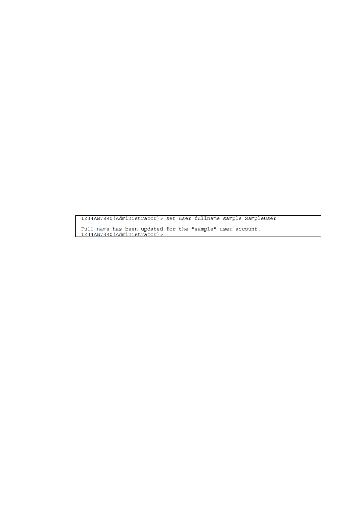
Registering a full user name
Overview
Configures a full name for a specified user.
Command name
SET USER FULLNAME
First Argument
<User name> (optional)
When you skip the user name, the user who is logging in the CLI will become the target user.
Second Argument
<Contact information>
Up to 32 characters to specify a contact information.
When <Contact information> is enclosed by double quotes (““) with nothing quoted between the
quotes, the current contact information will be cleared.
Example: „SET USER FULLNAME ““
Execution example
Example of execution of the command to configure a full name
Default value
None
Supplementary information
Only users with the ADMINISTRATOR or OPERATOR right can use this command.
93
Page 94

Configuring a password
Overview
Configures a user password specified by the argument.
Command name
SET USER PASSWORD
First Argument
<User name> (this argument is required)
Second Argument
<Password> (optional)
Specify a password by using three to eight alphanumeric characters.
Execution example
Default value
None
Supplementary information
Only users with the ADMINISTRATOR right can use this command.
94
Page 95
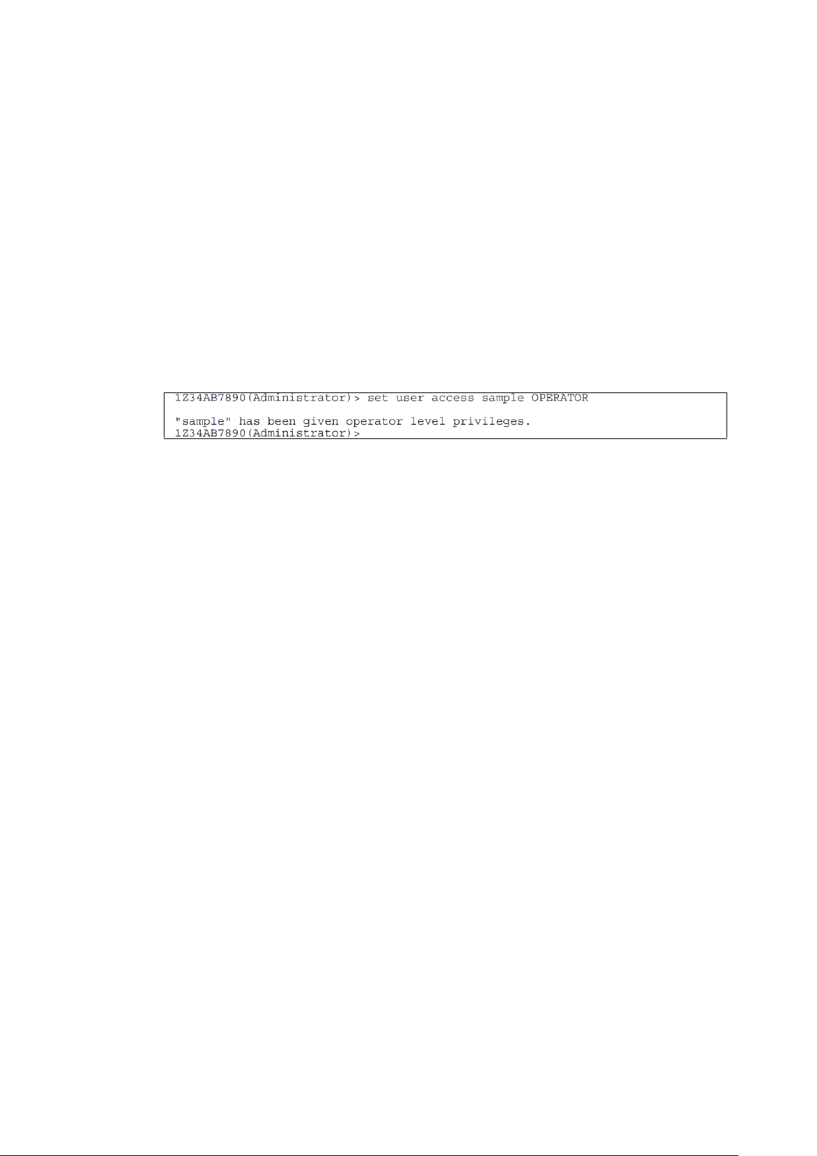
Configuring the access right
Overview
Configures a user access right specified by the argument.
Command name
SET USER ACCESS
First Argument
<User > (this argument is required)
Second Argument
<Access right>
“ADMINISTRATOR” or “OPERATOR” or “USER”
Execution example
Example of execution of the command to configure the access right for a user
Default value
Supplementary information
Only users with the ADMINISTRATOR right can use this command.
95
Page 96

Displaying the registered users
Overview
Displays the list of registered users.
Information to be displayed:
Full user name
User‟s contact
User‟s attribute (access right)
Command name
SHOW USER
First Argument
<User name> or “LIST” (displays all users)
Execution example
Example of execution of the command to display registered users
Default value
Supplementary information
96
Page 97

Cancelling user assignment (for CPU blade/switch module)
Overview
Cancels the access right for CPU blades and switch modules against a specified user.
Command name
UNASSIGN
First Argument
“SERVER” | “SWITCH”
Second Argument
<Slot number> | <Slot number> - <Slot number> | <Slot number> , <Slot number> | “ALL”
Slot number:
Slot number means CPU blade number for CPU blades.
Slot number means module number for switch modules.
Third Argument
<Registered user’s name>
Execution example
Default value
Supplementary information
Only users with the ADMINISTRATOR right can use this command.
Remarks of CLI command list show the detail of access rights.
97
Page 98

Cancelling user assignment (for EM card)
Overview
Cancels the access right for EM card against a specified user.
Command name
UNASSIGN
First Argument
“EM”
Second Argument
<Registered user’s name>
Execution example
Default value
Supplementary information
Only users with the ADMINISTRATOR right can use this command.
Remarks of CLI command list show the detail of access rights.
98
Page 99

System management commands
Forcefully disconnecting access to the EM serial console of switch
module
Overview
Terminates a serial console session on a switch module.
Command name
CLEAR SWITCH SESSION
Argument
<Slot number>
Within the range of 1 to 8.
Execution example
Default value
Supplementary information
99
Page 100

PING
Overview
Issues PING (ICMP Echo command) for a specified IP address or server name.
Command name
PING
First Argument
<The number of times PING is issued> (optional)
When you do not specify this argument, “4” is specified.
Second Argument
<IP address> or <Server name>
“Server name” can be specified when DNS is registered.
Execution example
Example of execution of the PING command
Default value
Supplementary information
100
 Loading...